
1. GENERAL · 1 TECHNICAL SPECIFICATIONS (For Road, Water supply, Pipe Line & Civil Works) 1....
144
1 TECHNICAL SPECIFICATIONS (For Road, Water supply, Pipe Line & Civil Works) 1. GENERAL (MORTH 5 th Reviced-Section-100) 1.1 Introduction These specifications shall apply to all such road and bridge works as are required to be executed under the Contract or otherwise directed by the Engineer-in-Charge (hereinafter referred to as the Engineer). In every case, the work shall be carried out to the satisfaction of the Engineer and conform to the location, lines, dimensions, grades and cross-sections shown on the drawings or as decided by the Engineer. The quality of materials, processing of materials as may be needed at the site, salient features of the construction work and quality of finished work, measures for safety of workers and public and traffic arrangements during execution shall comply with the requirements set forth in succeeding sections. Where the drawings and Specifications describe a portion of the work only in general terms, and not in complete detail, it shall be understood that only the sound engineering practice is to prevail, materials and workmanship of the best quality are to be employed and the instructions of the Engineer are to be fully complied with. A list of Indian Roads Congress (IRC) Specifications and recommended Codes of Practice which have been referred in these Specifications is given at Appendix-1. The latest edition of all Specifications/Standards/Codes of IRC till 60 (sixty) days before the final date of submission of the tender, shall be adopted. In case of any conflict or inconsistency in the provisions of the applicable Specifications/ Standards/Codes of IRC, provisions contained in these Specifications shall apply. 1.2 Definitions The words like Contract, Contractor, Engineer (synonymous with Engineer-in-charge), Drawings, Employer, Government, Works and Work Site used in these Specifications shall be considered to have the meaning as understood from the definitions of these terms given in the General Conditions of Contract. 1.3 Material and Test Standards The relevant standards for materials, as well as the testing procedures, have been indicated at appropriate places in the specifications. A list of these standards with their full title are included at Appendix-2 (Pl referred Morth 5 th Revision). 1.4 Sieve Standards The sieve designations referred to in the Specifications correspond to those specified by Bureau of Indian Standards in IS: 460. Table 100-1(Pl referred Morth 5 th Revision) gives the list of the commonly used IS sieves. 1.5 Scope of Work 1.5.1 The work to be carried out under the Contract shall consist of the various items as generally described in the Contract Documents as well as in the Bill of Quantities furnished in the Contract Documents. 1.5.2 Conformity with Drawings/Allowable Deviations 1.5.2.1 All works performed and all materials furnished shall be in conformity with the lines, grades, typical sections, dimensions, material requirements, and tolerances shown in the drawings or as indicated in the Specifications. 1.5.2.2 The works to be performed shall also include all general works preparatory to the construction of roads. Bridges, structures, canal crossings, drainage and all other related works. The works shall include work of any kind necessary for the due and satisfactory construction,
Transcript of 1. GENERAL · 1 TECHNICAL SPECIFICATIONS (For Road, Water supply, Pipe Line & Civil Works) 1....
1
TECHNICAL SPECIFICATIONS
(For Road, Water supply, Pipe Line & Civil Works)
1. GENERAL (MORTH 5th Reviced-Section-100) 1.1 Introduction
These specifications shall apply to all such road and bridge works as are required to be executed under the Contract or otherwise directed by the Engineer-in-Charge (hereinafter referred to as the Engineer). In every case, the work shall be carried out to the satisfaction of the Engineer and conform to the location, lines, dimensions, grades and cross-sections shown on the drawings or as decided by the Engineer. The quality of materials, processing of materials as may be needed at the site, salient features of the construction work and quality of finished work, measures for safety of workers and public and traffic arrangements during execution shall comply with the requirements set forth in succeeding sections. Where the drawings and Specifications describe a portion of the work only in general terms, and not in complete detail, it shall be understood that only the sound engineering practice is to prevail, materials and workmanship of the best quality are to be employed and the instructions of the Engineer are to be fully complied with. A list of Indian Roads Congress (IRC) Specifications and recommended Codes of Practice which have been referred in these Specifications is given at Appendix-1. The latest edition of all Specifications/Standards/Codes of IRC till 60 (sixty) days before the final date of submission of the tender, shall be adopted. In case of any conflict or inconsistency in the provisions of the applicable Specifications/ Standards/Codes of IRC, provisions contained in these Specifications shall apply. 1.2 Definitions
The words like Contract, Contractor, Engineer (synonymous with Engineer-in-charge), Drawings, Employer, Government, Works and Work Site used in these Specifications shall be considered to have the meaning as understood from the definitions of these terms given in the General Conditions of Contract. 1.3 Material and Test Standards
The relevant standards for materials, as well as the testing procedures, have been indicated at appropriate places in the specifications. A list of these standards with their full title are included at Appendix-2 (Pl referred Morth 5th Revision). 1.4 Sieve Standards
The sieve designations referred to in the Specifications correspond to those specified by Bureau of Indian Standards in IS: 460. Table 100-1(Pl referred Morth 5th Revision) gives the list of the commonly used IS sieves. 1.5 Scope of Work
1.5.1 The work to be carried out under the Contract shall consist of the various items as generally described in the Contract Documents as well as in the Bill of Quantities furnished in the Contract Documents. 1.5.2 Conformity with Drawings/Allowable Deviations
1.5.2.1 All works performed and all materials furnished shall be in conformity with the lines, grades, typical sections, dimensions, material requirements, and tolerances shown in the drawings or as indicated in the Specifications. 1.5.2.2 The works to be performed shall also include all general works preparatory to the construction of roads. Bridges, structures, canal crossings, drainage and all other related works. The works shall include work of any kind necessary for the due and satisfactory construction,

2
completion and maintenance of works to the intent and meaning of the drawings and these Specifications and further drawings and orders that may be issued by the Engineer from time to time. The scope of work shall include compliance by the Contractor with all Conditions of Contract, whether specifically mentioned or not in the various Sections of these Specifications, all materials, apparatus, plant, equipment, tools, fuel, water, strutting, timbering, transport, offices, stores, workshop, staff, labour and the provision of proper and sufficient protective works, diversions, temporary fencing and lighting. It shall include all works related to safety of road user. It shall also include safety of workers at construction site, first aid equipment, suitable accommodation for the staff and workmen with adequate sanitary arrangements, the effecting and maintenance of all insurances, the payment of all wages, salaries, fees, royalties, duties or other charges arising out of the erection of works and the regular clearance of rubbish, reinstatement and clearing-up of the site as may be required on completion of works, safety of the public and protection of the works and adjoining land/ structures. 1.5.3 The Contractor shall ensure that all actions are taken to build in quality assurance (QA) in the planning, management and execution of works. The quality assurance shall coverall stages of work such as setting out, selection of materials, selection of construction methods, selection of equipment and plant, deployment of personnel and supervisory staff, quality control testing, etc. The QA programme shall cover the details as per IRC: SP: 47 and IRC: SP: 57. These shall broadly cover quality assurance aspects of all services rendered, all items to be supplied and all activities to be performed under the contract including temporary structures and equipment which will influence the quality of the completed works or the progress of the contract. As a minimum, it shall cover the following: i) Organization and management responsibility, ii) Document and data control, iii) Construction programme, iv) Method statement, v) Process control, vi) Working, inspection, testing and documentary procedures, vii) Arrangement for smooth and safe traffic flow during construction and maintenance, viii) Control and documentation of purchasing and handling of materials, ix) Maintenance of records for non-conformity and timely corrective actions, x) Internal quality audit, xi) Training of staff, xii) Environment Management Plan (EMP). The QA plan shall be submitted to the Engineer for approval, not later than 28 days from the date of signing of the contract agreement. The work of building in quality assurance shall be deemed to be covered in the scope of the work. 1.5.4 The Contractor shall furnish, at least 7 days in advance, unless otherwise stipulated in the contract, his programme of commencement of each item of work, including the method statement including deployment of plant and equipment for the works included in the contract and any other work for which the Engineer may demand the method statement. He shall provide all information to the satisfaction of the Engineer to ensure its adequacy. The sole responsibility for the safety and adequacy of the methods adopted by the Contractor will, however, rest on the Contractor, irrespective of any approval given by the Engineer.

3
1.5.5 Inspection of Materials before Incorporation 1.5.5.1All materials shall be inspected, tested and accepted by the Engineer as per these specifications, before incorporation in the work. The frequencies and methods of sampling and testing materials, including those required for definite purpose and not covered by these specifications shall be in accordance to the relevant IRC or BIS or AASHTO/ASTMI BS Standards in order of priority. 1.5.5.2All materials or work not conforming to the requirements of the Specifications shall be considered unacceptable and rejected. The unacceptable materials or work that are rejected shall be immediately removed unless the defects are corrected and approved by the Engineer. If the Contractor fails to comply promptly with any order of the Engineer made under the provisions of this Clause, the Engineer has the authority to remove and replace unacceptable materials or work and to deduct from money due to the Contractor the cost of removal and replacement. 1.6 Inspection of Material at Source
The Engineer may choose to inspect material at source. In the event, the following conditions shall be met. a) The Contractor and the manufacturer of material shall assist and co-operate with the Engineer in carrying out the inspection. b) The Engineer shall have right to enter areas of plant where the manufacture or production of material is carried out. 1.7 Delivery, Storage and Handling of Materials
1.7.1 All materials shall be handled and stored in appropriate manner to preserve their quality and fitness for the work. During the handling of all aggregates or other construction materials, special care shall be taken to prevent contamination. Furthermore, aggregate shall be handled in such a manner as to prevent segregation. 1.7.2 Vehicles used in transporting construction material shall be kept clean and in proper working condition so as to prevent the loss of materials during transportation and meet the requirements of the Specifications. 1.7.3 The Contractor may be allowed to store materials and equipment within the right-of-way at location approved by the Engineer, but shall be responsible for the restoration and repair of any damage to plantation, signs, property or any assets resulting from such operations. Any additional space that may be needed for storage purposes and for placing of plant and equipment shall be provided by the Contractor at no additional cost to the Employer. 1.8 Materials Furnished by the Employer
When the Contract provides that certain materials required to complete the work will be supplied by the Employer, such material will be delivered or made available to the Contractor at the location(s) specified in the Contract. The Contractor shall be responsible for all damages occurring to the materials furnished by the Employer while the materials are in his possession. Any demurrage or storage charges shall also be the responsibility of the Contractor. The Contractor shall include the cost of handling, transportation and placing all Employer furnished materials in the Contract unit price for the relevant pay item. 1.9 Law to be observed
The Contractor shall observe and comply with all Central and State laws, local laws and ordinance which affect those employed on the work or affect the conduct of the work. The Contractor shall provide all safeguards, safety devices, and protective equipment and take any other actions necessary for safety and health of employees on the project.

4
1.10 Patented Devices, Materials and Processes If the Contractor is required or desires with the approval of the Engineer to use any design, device, material or process covered by trademark, patent or copyright, the Contractor shall obtain the right for its use by legal agreement with the patentee or owner. A copy of the agreement shall be furnished to the Engineer. Contract prices shall include all royalties and costs arising from patents, trademarks and copyrights. 1.11 Construction equipment
In addition to the conditions indicated in the Contract Documents, the following conditions regarding use of equipment in works shall be satisfied: a) The Contractor shall be required to give a trial run of the equipment for establishing their capability to achieve the laid down Specifications and tolerances to the satisfaction of the Engineer before commencement of the work; b) All equipment provided shall be of proven efficiency and shall be operated and maintained at all times in a manner acceptable to the Engineer; c) Plants, equipment and instruments provided shall have adequate sensitivity, facility for calibration to desired level and shall be robust; d) Plant, equipment and instrument provided shall have data logging arrangement and control systems to enable automatic feedback control of process; e) Plants, equipment and instruments provided shall have adequate safety features and pollution control devices; f) Plant, equipment and instruments provided shall be operated by skilled and qualified operators; g) All the plant/equipment to be deployed on the works shall be got approved from the Engineer for ensuring their fitness and efficiency before commencement of work; h) Any material or equipment not meeting the approval of the Engineer shall be removed from the site forthwith; i) No equipment shall be removed from site without permission of the Engineer; j) The Contractor shall also make available stand by equipment and spare parts; and k) The Contractor shall also make available equipment for site quality control work as directed by the Engineer. 1.12 Drawing
The drawings provided in the Tender Documents shall be used as reference only. The Contractor shall study the nature and type of work and ensure that the rate sand prices quoted by him in the Bill of Quantities have due consideration of the site and complexities of work involved during actual execution/construction. The Contractor based on his surveys and investigations, shall submit the working drawings (hard and soft copy) to the Engineer for each activity at least 45 days in advance of the scheduled date to the start of the activity as per his approved work programme. The working drawings shall clearly show the modifications, if any, proposed with reference to corresponding tender drawings. The Engineer shall review the working drawings including the modifications proposed, if any, revise the drawings, if required, approve and issue to the Contractor two copies of Good for Construction (GFC) drawings at least 28 days in advance of the scheduled date of the start of the activity. Examination and/or approval by the Engineer of any drawings or other documents submitted by the Contractor shall not relieve the Contractor of his responsibilities or liabilities under the Contract. The tendered rates/prices for the work shall be deemed to include the cost of

5
preparation, supply and delivery of all necessary drawings, prints, tracings and negatives which the Contractor is required to provide in accordance with the Contract. 1.13 Site information
The information about the site of work and site conditions in the Tender Documents is given in good faith for guidance only but it shall be the responsibility of the Contractor to satisfy himself regarding all aspects of site conditions. The information about the site of work and site conditions in the Tender Documents is given in good faith for guidance only but it shall be the responsibility of the Contractor to satisfy himself regarding all aspects of site conditions. Whereas the right-of-way to the bridge sites/road works shall be provided to the Contractor by the Employer, the Contractor shall have to make his own arrangement for the land required by him for site offices, field laboratory, site for plants and equipment, maintenance and repair workshop, construction workers' camp, stores etc. 1.14 Setting Out
The Contractor shall establish working bench marks tied with the Reference bench mark in the area soon after taking possession of the site. The Reference bench mark for the area shall be as indicated in the Contract Documents and the values of the same shall be obtained by the Contractor from the Engineer. The working bench marks shall be at the rate of four per km and also at or near all drainage structures, over-bridges and underpasses. The working bench marks /levels should be got approved from the Engineer. Checks must be made on these bench marks once every month and adjustments, if any, got approved from the Engineer and recorded. An up-to-date record of all bench marks including approved adjustments, if any, shall be maintained by the Contractor and also a copy supplied to the Engineer for his record. The lines and levels of formation, side slopes, drainage works, carriageways and shoulders shall be carefully set out and frequently checked, care being taken to ensure that correct gradients and cross-sections are obtained everywhere. In order to facilitate the setting out of the works, the center line of the carriageway or highway must be accurately established by the Contractor and approved by the Engineer. It must then be accurately referenced in a manner satisfactory to the Engineer, at every 50 m intervals in plain and rolling terrains and 20 m intervals in hilly terrain and in all curve points as directed by the Engineer, with marker pegs and chainage boards set in or near the fence line, and a schedule of reference dimensions shall be prepared and supplied by the Contractor to the Engineer. These markers shall be maintained until the works reach finished formation level and are accepted by the Engineer. On construction reaching the formation level stage, the center line shall again be set out by the Contractor and when approved by the Engineer, shall be accurately referenced in a manner satisfactory to the Engineer by marker pegs set at the outer limits of the formation. No reference peg or marker shall be moved or withdrawn without the approval of the Engineer and no earthwork or structural work shall commence until the center line has been referenced. The Contractor will be the sole responsible party for safe-guarding all survey monuments, bench marks, beacons, etc. The Engineer will provide the Contractor with the data necessary for setting out the center line. All dimensions and levels shown on the drawings or mentioned in documents forming part of or issued under the Contract shall be verified by the Contractor on the site and he shall immediately inform the Engineer of any apparent errors or discrepancies in such dimensions and levels. The Contractor shall, in connection with the staking out of the center line, survey the terrain along the road and shall submit to the Engineer for his approval, a profile along the road center line and cross-sections at intervals as required by the Engineer. The construction staking shall be done by personnel who are trained and experienced in construction layout and staking of the type and kind required in the Contract. Field notes shall be kept in standard, bound field notebooks as approved by the
6
Engineer. Field notes shall be subject to inspection by the Engineer and shall be the property of the Employer. The Contractor shall correct any deficient staking or construction work which resulted from inaccuracies in the staking operations or from the Contractor's failure to report inaccuracies in the plans or survey data furnished by the Department. After obtaining approval of the Engineer, work on earthwork can commence. The profile and cross-sections as per Section 305, shall form the basis for measurements and payment. The Contractor shall be responsible for ensuring that all the basic traverse points are in place at the commencement of the contract and, if any, are missing, or appear to have been disturbed, the Contractor shall make arrangements to re-establish these points. A "survey File" containing the necessary data will be made available for this purpose. If in the opinion of the Engineer, design modifications of the centre line or grade are advisable, the Engineer will issue detailed instructions to the Contractor and the Contractor shall perform the modifications in the field, as required, and modify the ground levels on the cross-sections accordingly as many times as required. There will be no separate payment for any survey work performed by the Contractor. The cost of these services shall be considered as being included in the rate of the items of work in the Bill of Quantities. Precision automatic levels, having a standard deviation of ±2 mm per km, and fitted with micrometer attachment shall be used for all double run levelling work. Setting out of the road alignment and measurement of angles shall be done by using Total Station with traversing target, having an accuracy of one second. Measurement of distances shall be done preferably using precision instruments like Diatomite. The work of setting out shall be deemed to be a part of general works preparatory to the execution of work and no separate payment shall be made for the same. 1.15 Public utilities
Drawings scheduling the affected services like water pipes, sewers, oil pipelines, cables, gas ducts etc. owned by various authorities including Public Undertakings and Local Authorities included in the Contract Documents shall be verified by the Contractor for the accuracy of the information prior to the commencement of any work. The Contractor shall notify all utility agencies who may have installation in the work area and secure their assistance in locating and identifying all utilities before starting any work that may cause any damage to such utilities. The Contractor shall schedule work in such a manner as to protect existing utility facilities until they are relocated, abandoned or replaced. The Contractor shall ensure that all utilities encountered within the Right of Way i.e. OFC Cable, telephone, power, water supply, sewerage or any others, remain operational at all times. Any utility, if damaged, due to construction operation, shall be promptly repaired by the Contractor at his cost. Notwithstanding the fact that the information on affected services may not be exhaustive, the final position of these services within the works shall be supposed to have been indicated based on the information furnished by different bodies and to the extent the bodies are familiar with the final proposals. The intermediate stages of the works are, however, unknown at the design stage, these being dictated by the Contractor's methods of working. Accordingly, the Contractor's programme must take into account the period of notice and duration of diversionary works of each body as given on the Drawings and the Contractor must also allow for any effect of these services and alterations upon the Works and for arranging regular meetings with the various bodies at the commencement of the Contract and throughout the period of the Works, the Contractor shall have no objection if the public utility bodies vary their decisions in the execution of their proposals in terms of programme and construction, provided that, in the opinion of the Engineer, the Contractor has received reasonable notice thereof before the relevant alterations are put in hand. No removal of or alterations to the utility shall be carried out unless written instructions are issued by the
7
Engineer. Any services affected by the Works must be temporarily supported by the Contractor who must also take all measures reasonably required by the various bodies to protect their services and property during the progress of the Works. The Contractor may be required to carry out certain works for and on behalf of various bodies, which he shall provide, with the prior approval of the Engineer. The work of temporarily supporting and protecting the public utility services during execution of the Works shall be deemed to be part of the Contract and no extra payment shall be made for the same. The Contractor shall be responsible to co-ordinate with the service providers for cutting of trees, shifting of utilities, removal of encroachments etc. to make site unencumbered for completion of work. This will include frequent follow-up meetings. Coordination for making project site unencumbered shall be deemed to be part of the Contract and no extra payment shall be made for the same. In some cases, the Contractor may be required to carry out the removal or shifting of certain services/utilities on specific orders from the Engineer for which payment shall be made to him. Such works, however, shall be taken up by the Contractor only after obtaining clearance from the Engineer and ensuring adequate safety measures. 1.16 Precautions for safeguarding the environment
1.16.1General
The Contractor shall take all precautions for safeguarding the environment during the course of the construction of the works. He shall abide by all laws, rules and regulations in force governing pollution and environmental protection that are applicable in the area where the works are situated. 1.16.2 Borrow Pits for Embankment Construction
Borrow pits shall be selected only after testing the suitability of materials for use in construction and shall not normally be dug in the right-of-way of the road. The stipulations in Section 305.2.2 shall govern. The borrow pits shall not be left in a condition likely to cause hazard to human and animal life. The Contractor shall seek prior approval from the concerned authorities for operating the borrow pits. 1.16.3 Quarry Operations
The Contractor shall obtain materials from quarries only after obtaining the consent of the Mining Department or other concerned authorities. The quarry operations shall be undertaken within the purview of the rules and regulations in force. 1.16.4 Control of Soil Erosion, Sedimentation and Water Pollution
The Contractor shall carry out the works in such a manner that soil erosion is fully controlled, and sedimentation and pollution of natural water courses, ponds, tanks and reservoirs is avoided. The stipulations in Clause 306 shall govern. 1.16.5 Pollution from Plants and Batching Plants
Stone crushing and screening plants, bituminous hot-mix plants, concrete batching plants etc. shall be located sufficiently away from habitation, agricultural operations or industrial establishments. The locations shall be as permissible under the laws governed by local bodies’ administration of the area. The Contractor shall take every precaution to reduce the levels of noise, vibration, dust and emissions from his plants and shall be fully responsible for any claims or damages caused to the owners of property, fields and residences in the vicinity and violation of pollution control norms, if any. 1.16.6 Substances Hazardous to Health
The Contractor shall not use or generate any materials in the works which are hazardous to the health of persons, animals or vegetation. Where it is necessary to use some substances

8
which can cause injury to the health of workers, the Contractor shall provide protective clothing or appliances to his workers 1.16.7 Use of Nuclear Gauges
Nuclear gauges shall be used only where permitted by the Engineer. The Contractor shall provide the Engineer with a copy of the regulations governing the safe use of nuclear gauges he intends to employ and shall abide by such regulations. 1.16.8 Environmental Protection
1.16.8.1 The Contractor must take all reasonable steps to minimize dust nuisance during the construction of the works along the haul roads and the worksites by sprinkling water at a frequency specified by the Engineer. All existing highways and roads used by vehicles or equipment’s of the Contractor or any of his sub-contractors or suppliers of materials or plant, and similarly any new roads which are part of the works and which are being used by traffic, shall be kept clean and clear of all dust mud or other extraneous materials dropped by the said vehicles. Similarly, all dust mud or other extraneous materials from the works spreading on these highways shall be immediately cleared by the Contractor. Clearance shall be effected immediately by sweeping and removal of debris, and all dust, mud and other debris shall be removed entirely from the road surface. Additionally, if so directed by the Engineer, the road surface shall be hosed or watered using suitable equipment. Damages to existing road: Any structural damage and loss of riding surface caused to the existing roads by the Contractor's construction vehicles Equipment shall be made good without any extra cost. Compliance with the foregoing will not relieve the Contractor of any responsibility for complying with the requirements of any authority in respect of the roads used by him. 1.16.7.2 Air Quality
The Contractor shall device and implements methods of working to minimize dust, gaseous and other air-borne emissions and carry out the Works in such a manner as to minimize adverse impacts on the air quality. The Contractor shall utilize effective water sprays during delivery, manufacture, processing and handling of materials when dust is likely to be created, and to dampen stored materials during dry and windy weather. Stockpiles of friable materials shall be covered with clean tarpaulins, with applications of sprayed water during dry and windy weather. Stockpiles of materials or debris shall be dampened prior to their movement, except where this is contrary to the Specification. Any vehicle with open load-carrying area used for transporting potentially dust-producing material shall have properly fitting side and tail boards. Materials having the potential to produce dust shall not be loaded to a level higher than the side and tail boards and shall be covered with clean tarpaulins in good condition. The tarpaulin shall be properly secured and extend at least 300 mm over the edges of the side and tail boards. 1.16.7.3 Water Sources and Water Quality
The Contractor shall provide independent sources of water supply, such as bore wells, for use in the Works and for associated storage, workshop and work force compounds. Prior approval shall be obtained from the relevant State Authorities and all installations shall be in compliance with local regulations. The Contractor shall protect all watercourses, waterways, ditches, canals, drains, lakes, reservoirs and the like from pollution as a result of the execution of the Works. All water and other liquid waste products like petroleum products and chemicals arising on the Site shall be collected and disposed of at a location on or off the Site and in a manner that shall not cause either nuisance or pollution. The Contractor shall at all times ensure that all existing stream courses and drains within and adjacent to the Site are kept safe and free from any debris and any materials arising from the Works. The Contractor shall not discharge or
9
deposit any matter arising from the execution of the Works into any water course except with the permission of the Engineer and the regulatory authority concerned. 1.16.7.4 Construction Camps
The construction camps shall conform to the State and National building regulations as applicable. The area for the storage of polluted materials shall be stored on impervious floors and shall be surrounded by impervious ditches in order to avoid spilling of polluted material to surrounding areas. Construction camps shall be properly arranged to avoid noise pollution to the nearby habitants and to avoid contamination of water courses from wastewater drainage. To prevent such contamination, wastewater generated at the campsites shall be discharged into soak pits. Human excreta shall be treated though septic tanks prior to discharge and shall conform to directives and guidelines of the State. Water accumulated in tyres, empty vessels and containers of all nature will be regularly cleaned to avoid the related health hazards. The Contractor shall provide and maintain in a neat and sanitary condition accommodations for the use of the employees and workers as may be necessary to comply with the requirements of Central, State, and local regulations. Spilling of oil and bituminous products during construction and transport shall be avoided to reduce the chances of contamination of surface as well as ground water. 1.16.7.5 Occupational Health and Safety of the Workforce
The Contractor shall prepare and submit to the Engineer the Occupational Health & Safety Procedures/Practices for the workforce in all quarry sites, plant sites, work sites, camp sites, etc., in accordance with the applicable laws. 1.16.7.6 Control and Disposal of Wastes
The Contractor shall control the disposal of all forms of waste generated by the construction operations and in all associated activities. No uncontrolled deposition or dumping shall be permitted. Wastes to be so controlled shall include, but shall not be limited to, all forms of fuels and engine oils, all types of bitumen, cement, surplus aggregates, gravels, bituminous mixtures etc. The Contractor shall make specific provision for the proper disposal of these and any other waste products, conforming to local regulations and acceptable to the Engineer. 1.16.7.7 Transport of Hazardous Materials
Transport of hazardous materials, in bulk or in sealed containers, shall meet the requirements of the State regulations. Prior to ordering transport of hazardous material in bulk, the Contractor must obtain the approval of the relevant authority as well as of the Engineer. The transport of diesel, petrol, gaseous material, chemical and explosives for quarrying shall be governed by safety laws of the local authorities. Precautionary measures and conformity with regulations shall be stated in a Method Statement for the approval of the Engineer. Sealed containers of hazardous materials shall be stored in a well-ventilated room, well-guarded and secured. 1.16.7.8 Emergency Response
The Contractor shall plan and provide remedial measures to be implemented in the event of occurrence of emergencies such as spillages of oil or bitumen or chemicals, fire. The Contractor shall provide the Engineer with a statement of the measures he intends to implement in the event of such an emergency, which shall include a statement of how he intends to provide personnel adequately trained to implement such measures. 1.16.7.9 Measurement for Payment
The compliance of all provisions made in this Clause 111 shall be deemed to be incidental to the work and no separate measurement or payment shall be made. The Contractor shall be deemed to have made allowance for all such compliance with these provisions in the
10
preparation of his bid for items of work included in the Bill of Quantities and full compensation for such compliance shall be deemed to be covered by the bid price. 1.17 Arrangement for traffic during construction
1.17.1 General
The Contractor shall at all times, carry out work on the highway in a manner creating least interference to the flow of traffic while consistent with the satisfactory execution of the same. For all works involving improvements to the existing highway, the Contractor shall, in accordance with the directives of the Engineer, provide and maintain, during execution of the work, a passage for traffic either along a part of the existing carriageway under improvement or along a temporary diversion constructed close to the highway. Before taking up any construction or maintenance operation, the Contractor shall prepare a Traffic Management Plan for each work zone and submit it to the Engineer for prior approval. This plan should include inter alia: i) Provision of a qualified safety officer with support staff to serve as a site safety team ii) Provision of traffic safety devices and road signs in construction zones as per IRC: SP: 55 and other relevant IRC Codes and para 112.4: iii) Safety measures for the workers engaged including personal protection equipment iv) First aid and emergency response arrangements v) Details and drawings of arrangements in compliance with other sub Sections of this Section. 1.17.2 Passage of Traffic along a Part of the Existing Carriageway under Improvement For Widening/strengthening existing carriageway where part width of the existing carriageway is proposed to be used for passage of traffic, treated shoulders shall be provided on the side on which work is not in progress. The treatment to the shoulder shall consist of providing at least 150 mm thick granular (Wet Mix Macadam/Water Bound Macadam) base course covered with bituminous surface dressing in a width of at least 1.5 m and the treated shoulder shall be maintained throughout the period during which traffic uses the same to the satisfaction of the Engineer. The continuous length, in which such work shall be carried out, would be limited normally to 500 m at a place. However, where work is allowed by the Engineer in longer stretches passing places at least 20 m long with additional paved width of 2.5 m shall be provided at every 0.5 km interval. In case of eccentric widening of existing two-lane to four-lane, the additional two-lanes would be constructed first and the traffic diverted to it and only thereafter the required treatment to the existing carriageway would be carried out. In case of concentric widening, stipulations as in paragraph above shall apply. After the works are completed, with the approval of the Engineer, the treated shoulder shall be dismantled, the debris disposed of and the area cleared as per the direction of the Engineer. 1.17.3 Passage of Traffic along a Temporary Diversion
In stretches where it is not possible to pass the traffic on part width of the carriageway, a temporary diversion shall be constructed with 7 m carriageway and 2.5 m earthen shoulders on each side (total width of roadway 12 m) with the following provision for road crust in the 7 m width: i) Earthwork ii) 200 mm (compacted) granular sub-base iii) 225 mm (compacted) granular base course iv) Priming and Tack Coat and v) Premix carpet with Seal Coat/Mix Seal Surfacing The location of such stretch, alignment and longitudinal section of diversion including junctions and temporary cross drainage provision shall be as approved by the Engineer.
11
1.17.4 Traffic Safety and Control The Contractor shall take all necessary measures for the safety of traffic during construction and provide, erect and maintain such barricades, including signs, marking, flags, lights and flagmen as per the traffic management plan submitted by the Contractor and approved by the Engineer, referred to in Sub-Section 112.1. Before taking up any construction, an agreed phased programme for the diversion of traffic on the highway shall be drawn up in consultation with the Engineer. All construction equipment working or parked on or within the traffic lanes or shoulders under "Traffic maintained" conditions shall be equipped with flashing yellow beacons. The Contractor shall conduct all operations to minimize any drop-offs (abrupt changes in roadway) exposed to traffic. Drop-offs in the travelled way shall be protected by a wedge of compacted stable material capable of carrying traffic (the wedge being 1 vertical to 4 horizontal or flatter). The Engineer shall authorize other methods, to protect drop-offs when conditions do not allow a wedge of compacted, stable material. Warning signs, barricades, warning lights, and all other traffic control devices shall not be removed if the hazard has not been eliminated. Only upon receipt of specific written authorization from the Engineer, the Contractor may remove or cease to maintain warning signs, barricades, warning lights, and all other traffic control devices. The barricades erected on either side of the carriageway/portion of the carriageway closed to traffic, shall be of strong design to resist violation, and painted with alternate black and white stripes. Red lanterns or warning lights of similar type shall be mounted on the barricades at night and kept lit throughout from sunset to sunrise. At the points where traffic is to deviate from its normal path (whether on temporary diversion or part width of the carriageway) the channel for traffic shall be clearly marked with the aid of pavement markings, painted drums or a similar device to the directions of the Engineer. At night, the passage shall be delineated with lanterns or other suitable light source including solar energy bulbs. One-way traffic operation shall be established whenever the traffic is to be passed over part of the carriageway inadequate for two-lane traffic. This shall be done with the help of temporary traffic signals or flagmen kept positioned on opposite sides during all hours. For regulation of traffic, the flagmen shall be equipped with red and green flags and lanterns/lights. On both sides, suitable regulatory/warning signs as approved by the Engineer shall be installed for the guidance of road users. On each approach, at least two signs shall be put up, one close to the point where transition of carriageway begins and the other 120 m away. The signs shall be of approved design and of reflective type, as directed by the Engineer. 1.17.5 Maintenance of Diversions and Traffic Control Devices
Signs, lights, barriers and other traffic control devices, adequate lighting and other arrangements, as well as the riding surface of diversions and treated shoulders shall be maintained in a satisfactory condition till such time they are required and as directed by the Engineer. The temporary travelled way shall be kept free of dust by frequent applications of water, if necessary. 1.17.6 Measurements for Payment and Rate
All arrangements, as contained in this Section 112 for safety of road users, during construction including provision of temporary diversions/temporary cross drainage structures/treated shoulders shall be measured and paid as per the BOQ. However their maintenance, dismantling and clearing debris shall be considered as incidental to the Works and shall not be paid separately
1.18 General rules for the measurement of works for payment
12
1.18.1 General All measurements shall be made in the metric system. Different items of work shall be measured in accordance with the procedures set forth in the relevant Sections read in conjunction with the General Conditions of Contract. The same shall not, however, apply in the case of lump sum contracts. All measurements and computations, unless otherwise indicated, shall be carried nearest to limits (Pl referred Morth 5th revision section 100). In recording dimensions of work, the sequence of length, width and height or depth or thickness shall be followed. 1.18.2 Measurement of Lead for Materials
Where lead is specified in the Contract for construction materials, the same shall be measured as described hereunder: Lead shall be measured over the shortest practicable route and not the one actually taken and the decision of the Engineer in this regard shall be taken as final. Distances up to and including 100 m shall be measured in units of 50 m, exceeding 100 m but not exceeding 1 km in units of 100 m and exceeding 1 km in units of 500 m, the half and greater than half of the unit shall be reckoned as one as and less than half of the unit ignored. In this regard, the source of the material shall be divided into suitable blocks and for each block, the distance from the center of placing pertaining to that block shall be taken as the lead distance. 1.18.3 Measurement of Pavement Thickness for Payment on Volume Basis
The finished thickness of sub-bases, base and bituminous layers and concrete courses to be paid on volume basis shall be computed in the following manner: Levels shall be taken before and after construction, at the grid of points 10m centre-to-centre longitudinally in straight reaches and 5 m centre-to-centre at curves. Normally, on two-lane roads, the levels shall be taken at four positions transversely, at 0.75 m and 2.75 m from either edge of the carriageway and on single-lane roads, these shall be taken at two positions transversely, being at 1.25 m from either edge of the carriageway. For multi-lane roads, levels shall be taken at two positions transversely for each lane. The transverse position for levels shall be 0.75 m from either edge of the carriageway and the remaining locations shall be at equi-distance in the balance portion of carriageway. For paved shoulder an additional level shall be taken at the centre of the shoulder. Suitable references for the transverse grid lines should be left in the form of embedded bricks on both ends or by other means so that it is possible to locate the grid points for level measurements after each successive course is laid. For pavement courses laid only over widening portions, at least one line of levels shall be taken on each strip of widening, or more depending on the width of widening as decided by the Engineer. Notwithstanding the above, the measurements may be taken at closer intervals also, if so desired by the Engineer, the need for which may arise particularly in the case of estimation of the volume of the material for profile corrective course (levelling course). The average thickness of the pavement course in any area shall be the arithmetic mean of the difference of levels before and after construction at all the grid points falling in that area, provided that the thickness of finished work shall be limited to those shown on the drawings or approved by the engineer in writing. As supplement to level measurements, the Engineer shall have the option to take cores/ make holes to check the depth of construction. The holes made and the portions cut for taking cores shall be made good by the Contractor by laying fresh mix/material including compacting as required at his-own cost immediately after the measurements are recorded.
1.18.4 Checking of Pavement Thickness for Payment on Area Basis
13
Where payment for any bituminous course in Section 500 is allowed to be made on the area basis, the Engineer may have its thickness checked with the help of a suitable penetration gauge at regular intervals or other means as he may decide. 1.18.5 Measurement of Bituminous Courses for Payment on Weight Basis
Plant-mixed bituminous materials for pavement courses, where specifically designated in the contract to be paid on weight basis, shall be weighed on accurate scales approved by the Engineer. Approved scales shall mean scales that are of size, capacity, kind and type suitable for the weighing to be done, and these shall be properly installed and maintained. Prior to the use of the scales and as frequently thereafter as the Engineer may deem necessary to ensure accuracy, the scales shall be checked and approved by the Engineer, or the Engineer may direct the Contractor to have the scales checked by other competent agency at the cost of the Contractor. Location of the scales shall be as designated by the Engineer. Trucks used for hauling the material to be weighed shall be weighed empty daily at such times as the Engineer directs, and each truck shall bear a plainly legible identification mark. For materials specified to be measured by weight, the Engineer will have the option to make measurements of the finished work by volume in accordance with Section 113.3 and such volumes shall be converted into weight for payment purposes. The factor for conversion from volume measurement to weight measurement shall be computed from the representative density of the compacted material at site determined at locations approved by the Engineer. 1.19 Scope of rates for different items of work
1.19.1 For item rate contracts, the contract unit rates for different items of work shall be payment in full for completing the work to the requirements of the Specifications including full compensation for all the operations detailed in the relevant Sections of these Specifications under "Rates". In the absence of any directions to the contrary, the rates are to be considered as the full inclusive rate for finished work covering all labour, materials, wastage, temporary work, plant, equipment, over-head charges and profit as well as the general liabilities, performance of other obligations, insurance and risks arising out of the Conditions of Contract. 1.19.2 The item rates quoted by the Contractor shall, unless otherwise specified, also include compliance with/supply of the following: i) General works such as setting out, clearance of site before setting out and clearance of works after completion; ii) A detailed programme using modern project management software for the construction and completion of the work giving, in addition to construction activities, detailed network activities for the submission and approval of materials, procurement of critical materials and equipment, fabrication of special products/equipment and their installation and testing, for all activities of the Engineer/Employer that are likely to affect the progress of work, etc., including updating of all such activities on the basis of the decisions taken at the periodic site review meetings or as directed by the Engineer; iii) Samples of various materials proposed to be used on the Works for conducting tests thereon as required as per the provisions of the Contract; iv) Design of mixes as per the relevant Sections of the Specifications giving proportions of ingredients, sources of aggregates and binder along with accompanying trial mixes as per the relevant Sections of these Specifications to the submitted to the Engineer for his approval before use on the Works; v) Cost of laying trial stretches; vi) Detailed drawings as per Clause 107.
14
vii) Detailed design calculations and drawings for all Temporary Works (such as form-work, staging, centering, specialized constructional handling and launching equipment and the like); viii) Detailed drawings for templates, support and end anchorage, details for pre-stressing cable profiles, bar bending and cutting schedules for reinforcement, material lists for fabrication of structural steel, etc.; ix) Mill test reports for all mild and high tensile steel and cast steel as per the relevant provisions of the Specifications; x) Testing of various finished items and materials including bitumen, cement, concrete, bearings as required under these Specifications and furnishing test reports/certificates; xi) Inspection Reports in respect of formwork, staging, reinforcement and other items of work as per the relevant Specifications; xii) Any other data which may be required as per these Specifications or the Conditions of Contract or any other annexures/schedules forming part of the Contract; xiii) Any other item incidental to work which is necessary for complying with the provisions of the Contract; xiv) All temporary works, formwork and false work not included as separate item in the BOQ; xv) Establishing and running a laboratory with facilities for testing for various items or works as specified in Section 900 and other relevant Sections; xvi) Cost of in-built provisions for Quality Assurance; xvii) Cost of safeguarding the environment; and xviii) Cost of providing "as-built drawings" in original and two sets of prints. 1.19.3 Portions of road works beyond the limits and/or any other work may be got constructed by the Employer directly through other agencies. Accordingly, other agencies employed by the Employer may be working in the vicinity of the Works being executed by the Contractor. The Contractor shall liaise with such agencies and adjust his construction programme for the completion of work accordingly and no claim or compensation due to any reason whatsoever will be entertained on this account. The Employer will be indemnified by the Contractor for any claims from other agencies on this account. 1.20 Methodology and sequence of work
1.20.1 Prior to start of the construction activities at site, the Contractor shall, within 28 days after the date of the agreement unless otherwise stipulated in the Contract, submit to the Engineer for approval, the detailed method statement. The method statement shall be submitted in two parts. 1.20.2 The general part of the method statement shall describe the Contractor's proposals regarding preliminary works, common facilities and other items that require consideration at the early stage of the contract. The general part shall include information on: a) Sources of materials like coarse aggregates and fine aggregates, quantity and quality of materials available in different sources; b) Sources of manufactured materials like bitumen, cement, steel reinforcement, pre-stressing strands and bearings etc. He shall also submit samples/test certificates of materials for consideration of the Engineer; c) Locations of the site facilities such as batching plant, hot mix plant, crushing plant, etc.; d) Details of facilities available for transportation of men/material and equipment; e) Information on procedure to be adopted by the Contractor for prevention and mitigation of negative environmental impact due to construction activities; f) Safety and traffic arrangement during construction; g) Implementation of activities provided in the Environmental Management Plan; h) Any other information required by the Engineer.
15
The general part of the QA programme under Section 105.3 shall accompany the method statement. 1.20.3 Special part of the method statement shall be submitted to the Engineer by the Contractor for each important item of work as directed by the Engineer. The statement shall be submitted at least 4 weeks in advance of the commencement of the activity of item of work unless otherwise stipulated in the contract. The statement shall give information on: a) Details of the personnel both for execution and quality control of the work; b) Equipment deployment with details of the number of units, capacity, standby arrangement; c) Sequence of construction and details of temporary or enabling works like diversion, cofferdam, formwork including specialized formwork for superstructure, details of borrow areas, method of construction of embankment, sub-grade and pavement, pile concreting, proprietary processes and products and equipment’s to be deployed. Wherever required technical literature, design calculations and drawings shall be included in the method statement; d) Testing and acceptance procedure including documentation; e) The special part of the QA programme under Sub-Section 105.3 for the particular item of work shall accompany the method statement for the concerned activity. The Engineer shall examine and approve the method statement with the required modifications. The modified method statement if required shall be submitted within 14 days of the receipt of the Engineer's approval. The sole responsibility for adequacy and safety of the method adopted by the Contractor shall rest on the Contractor irrespective of any approval given by the Engineer. 1.20.4 Approval of Proprietary Products/Processes/Systems
Within 90 days of the signing of agreement, the Contractor shall submit the following information for all proprietary products, process or any other item proposed to be used in the work, for approval of the Engineer. a) Name of the manufacturer and name of the product/process/system along with authenticated copies of the license/collaboration agreement; b) General features of the product/process/system; c) Details of the product development and development testing; d) Acceptance test and criteria; e) Installation procedure; f) Maintenance procedure and schedule; g) Warranty proposal. The Engineer may order additional test for the purpose of acceptance. Additional charges for test, if any, for the product/process/system shall be borne by the Contractor. 1.21 Crushed stone aggregates
Where the terms crushed gravel/shingle, crushed stone, broken stone or stone aggregate appear in any part of the Contract Documents or Drawings issued for work, they refer to crushed gravel/crushed shingle/crushed stone aggregate obtained from integrated crushing plant having appropriate primary crusher, secondary cone crusher, vertical shaft impactor and vibratory screen unless specified otherwise. Stone retained on 4.75 mm sieve shall have at least two faces fractured 1.22 Supply of quarry samples
Raw and processed samples of the mineral aggregates from the approved quarry shall be submitted by the Contractor at his cost. 1.23 Approval of materials Approval of all sources of material for work shall be obtained in writing from the Engineer before their use on the works. 1.24 Use of surfaces by traffic
16
Ordinarily, no construction traffic shall be allowed on pavement under construction unless authorized by the Engineer. Even in that case, the load and intensity of construction traffic should be so regulated that no damage is caused to the sub-grade or pavement layers already constructed. Where necessary, service roads shall be constructed for this purpose and the same shall be considered as incidental to the work. The wheels or the tracks of plant moving over the various pavement courses shall be kept free of deleterious materials. Bituminous base course shall be kept clean and uncontaminated as long as the same remains uncovered by a wearing course or surface treatment. The only traffic permitted access to the base/binder course shall be that engaged in laying and compacting the wearing course or that engaged on such surface treatment where the base/binder course is to be blinded and/or surface dressed. Should the base/binder course or tack coat on the base/binder course become contaminated, the Contractor shall make good by cleaning it to the satisfaction of the Engineer, and if this is impracticable, by removing the layer and replacing it to Specifications without any extra cost to the employer. On Dry Lean Concrete sub-base, no heavy commercial vehicles like trucks and buses shall be permitted after its construction. Light vehicles, if unavoidable, may, however, be allowed after 7 days of its construction with prior approval of the Engineer. No vehicular traffic, shall be allowed on a finished concrete pavement for a period of 28 days of its construction and until the joints are permanently sealed and cured. 1.25 Field laboratory
1.25.1 Scope
The work covers the provision and maintenance of an adequately equipped field laboratory as required for site control on the quality of materials and the works. 1.25.2 Description
The Contractor shall arrange to provide fully furnished and adequately equipped field laboratory. The field laboratory shall preferably be located adjacent to the site office of the Engineer and provided with amenities like water supply, electric supply etc. as for the site office of the Engineer as described in this Section. The layout and size of the field laboratory shall be as indicated in the drawings. In case no drawings is furnished, the laboratory shall include space for the storage of samples, equipment, laboratory tables and cupboards, working space for carrying out various laboratory tests, a wash basin, toilet facility and a curing tank for the curing of samples, around 4 m x 2 m x 1 m in size and a fume chamber. Wooden/concrete working table with a working platform area of about 1 m x 10m shall be provided against the walls. Wooden cupboards above and below the working tables shall be provided to store accessories such as, sample moulds etc. At least 4 racks of slotted angles and M.S. sheets the size 1800 mm x 900 mm x 375 mm and at least 6 stools for laboratory test operators shall also be provided. The items of laboratory equipment shall be provided in the field laboratory depending upon the items to be executed as per Table 100-2(Pl referred Morth 5th revision). 1.25.3 Ownership
The field laboratory building and equipment shall be the property of the Contractor. The Employer and the Engineer shall have free access to the laboratory. 1.25.4 Maintenance
The Contractor shall arrange to maintain the field laboratory in a satisfactory manner until the issue of Taking over Certificate for the completed work. Maintenance includes all activities described in Section 120.4(Pl referred Morth 5th revision). 1.25.5 Rate
Provision and maintenance of the field laboratory is not a payable item as it is incidental to the work.
17
1.26 SUPPLY OF PROJECT RECORD
1.26.1 Scope
The work covers the supply digital record of project events in digital format (DVD/Flash Drive) including colored photographs both in digital format as well as mounted on albums to serve as a permanent record of the work needed for an authentic documentation, as approved by the Engineer. 1.26.2 Description
The Contractor shall provide the following project records in digital format (DVD/Flash Drive) as directed by the Engineer: i) Record of work in each work front: It shall cover the status of each work front before start of work, during various stages of construction and after completion duly including the arrangements made (day & night) for traffic during construction (This shall be need based or as directed by the Engineer); ii) Record of quarry sites, plant sites, camp sites including labour camps, haul roads, access roads, etc. on quarterly basis; iii) Record of all accidents on project road/various sites (quarry, plant, camp, etc.) The record shall be taken by a professional with a digital camera capable of taking still as well as video images having the facility to record the date and the background commentary. The Contractor shall keep separate discs/drives, one with the Engineer and the other with the Employer and update the data in these discs/drives on monthly basis. Separately, a video (in digital format) of maximum one hour duration covering interesting and novel features of the work duly editing the above master disc/drive shall also be maintained, one copy each kept with the Engineer and the Employer and updated on monthly basis. All recording shall be done in the presence of the Engineer's Representative who will certify in writing the recording. 1.26.3 Measurements for Payment
Supply of two copies of all digital records as above and color record photographs both in digital format as well as mounted in the albums project shall be measured as one item for the project. Supply of additional prints of color record photograph if requested shall be measured in number of additional prints supplied. The supply of "as-built" drawings in digital format and in hard copies is incidental to the work and shall not be a payable item. 1.26.4 Rate
Supply of project record in digital format in two copies (one for the Engineer and the other for the Employer) including video recordings updated on monthly basis throughout the construction period shall be measured as one single item.
2. CLEARING AND GRUBBING, DISMANTLING CULVERTS,
BRIDGES AND OTHER STRUCTURES/PAVEMENTS (MORTH 5th Reviced-Section-200)
2.1 Cleaning and Grubbing
2.1.1 Scope: - This work shall consist of cutting, removing and disposing of all materials such as trees, bushes, shrubs, stumps, roots, grass, weeds, rubbish, top organic soil, etc. to an average depth of 150 mm in thickness, which in the opinion of the Engineer are unsuitable for incorporation in the works, from the area of road land containing road embankment, drains, cross-drainage structures and such other areas as may be specified on the drawings or by the Engineer. It shall include

18
necessary excavation, backfilling of pits resulting from uprooting of trees and stumps to required compaction, handling, salvaging, and disposal of cleared materials with all leads and lifts. Clearing and grubbing shall be performed in advance of earthwork operations and in accordance with the requirements of these Specifications. 2.1.2 Preservation of Property/Amenities:- Roadside trees, shrubs, any other plants, pole lines, fences, signs, monuments, buildings, pipelines, sewers and all highway facilities within or adjacent to the highway which are not to be disturbed shall be protected from injury or damage. The Contractor shall provide and install at his own cost, suitable safeguards approved by the Engineer for this purpose. During clearing and grubbing, the Contractor shall take all adequate precautions against soil erosion, water pollution, etc., and where required, undertake additional works to that effect vide Clause 306. Before start of operations, the Contractor shall submit to the Engineer for approval, his work plan including the procedure to be followed for disposal of waste materials, etc., and the schedules for carrying out temporary and permanent erosion control works as stipulated in Clause 306.3. 2.1.3 Methods, Tools and Equipment: - Only such methods, tools and equipment as are approved by the Engineer and which will not affect any property to be preserved shall be adopted for the Work. If the area has thick vegetation/roots/trees, a crawler or pneumatic tyred dozer of adequate capacity may be used for clearance purposes. The dozer shall have ripper attachments for removal of tree stumps. All trees, stumps, etc., falling within excavation and fill lines shall be cut to such depth below ground level that in no case these fall within 500 mm of the bottom of the subgrade. Also, all vegetation such as roots, under-growth, grass and other deleterious matter unsuitable for incorporation in the embankment subgrade shall be removed between fill lines to the Satisfaction of the Engineer. All branches of trees extending above the roadway shall be trimmed as directed by the Engineer. All excavations below the general ground level arising out of the removal of trees, stumps, etc., shall be filled with suitable material and compacted thoroughly so as to make the surface at these points conform to the surrounding area. Ant-h ills both above and below the ground, as are liable to collapse and obstruct free subsoil water flow shall be removed and their workings, which may extend to several meters, shall be suitably treated. 2.1.4 Disposal of Materials:- All materials arising from clearing and grubbing operations shall be taken over and shall be disposed of by the Contractor at suitable disposal sites with all leads and lifts. The disposal shall be in accordance with local, State and Central regulations. 2.1.5 Measurements for Payment: -
Clearing and grubbing for road embankment, drains and cross-drainage structures shall be measured on area basis in terms of hectares. Cutting of trees up to 300 mm in girth and removal of their stumps, including removal of stumps up to 300 mm in girth left over after trees have been cut by any other agency, and trimming of branches of trees extending above the roadway and backfilling to the required compaction shall be considered incidental to the clearing and grubbing operations. Clearing and grubbing of borrow areas shall be deemed to be a part of works preparatory to embankment construction and shall be deemed to have been included in the rates quoted for the embankment construction item and no separate payment shall be made for the same. Ground levels shall be taken prior to and after clearing and grubbing. Levels taken prior to clearing and grubbing shall be the base level and will be accordingly used for assessing the depth of clearing and grubbing and computation of quantity of any unsuitable material which

19
is required to be removed. The levels taken subsequent to clearing and grubbing shall be the base level for computation of earthwork for embankment. Cutting of trees, excluding removal of stumps and roots of trees of girth above 300 mm shall be measured in terms of number according to the girth sizes given below :-
i) Above 300 mm to 600 mm ii) Above 600 mm to 900 mm
iii) Above 900 mm to 1800 mm iv) Above 1800 mm
Removal of stumps and roots including backfilling with suitable material to required compaction shall be a separate item and shall be measured in terms of number according to the sizes given below:-
i) Above 300 mm to 600 mm ii) Above 600 mm to 900 mm
iii) Above 900 mm to 1800 mm iv) Above 1800 mm
For the purpose of cutting of trees and removal of roots and stumps, the girth shall be measured at a height of 1 m above ground or at the top of the stump if the height of the stump is less than one meter from the ground. 2.1.6 Rates:- The Contract unit rates for the various items of clearing and grubbing shall be payment in full for carrying out the required operations including full compensation for all labour, materials, tools, equipment and incidentals necessary to complete the work. These will also include removal of stumps of trees less than 300 mm girth excavation and backfilling to required density, where necessary, and handling, giving credit towards salvage value disposing of the cleared materials with all lifts and leads. Clearing and grubbing done in excess of 150 mm by the Contractor shall be made good by the Contractor at his own cost as per Clause 301.3.3 to the satisfaction of the Engineer prior to taking up earthwork. Where clearing and grubbing is to be done to a level beyond 150 mm, due to site considerations, as directed by the Engineer, the extra quantity shall be measured and paid separately. The Contract unit rate for cutting trees of girth above 300 mm shall include handling, giving credit towards salvage value disposing of the cleared materials with all lifts and leads. The Contract unit rate for removal of stumps and roots of trees girth above 300 mm shall include excavation and backfilling with suitable material to required compaction, handling, giving credit towards salvage value disposing of the cleared materials with all lifts and leads. The Contract unit rate is deemed to include credit towards value of usable materials, salvage value of unusable materials and off-set price of cut trees and stumps belonging to the Forest Department. The off-set price of cut trees and stumps belonging to the Forest Department shall be deducted from the amount due to the Contractor and deposited with the State Forest Department. In case the cut trees and stumps are required to be deposited with the Forest Department the Contractor shall do so and no deduction towards the off-set price shall be effected. The offset price shall be as per guidelines / estimates of the State Forest Department. Where a Contract does not include separate items of clearing and grubbing, the same shall be considered incidental to the earthwork items and the Contract unit prices for the same shall be considered as including clearing and grubbing operations.
2.2 Dismantling culverts, bridges and other structures/pavements
2.2.1 Scope:-
20
This work shall consist of dismantling and removing existing culverts, bridges, pavements, kerbs and other structures like guard-rails, fences, utility services, manholes, catch basins, inlets, etc., from the right of way which in the opinion of the Engineer interfere with the construction of road or are not suitable to remain in place, disposing of the surplus/unsuitable materials and backfilling to after the required compaction as directed by the Engineer. Existing culverts, bridges, pavements and other structures which are within the highway and which are designated for removal, shall be removed up to the limit and extent specified in the drawings or as indicated by the Engineer. Dismantling and removal operations shall be carried out with such equipment and in such a manner as to leave undisturbed, adjacent pavement, structures and any other work to be left in place. All operations necessary for the removal of any existing structure which might endanger new construction shall be completed prior to the start of new work. 2.2.2 Dismantling Culverts and Bridges: - The structures shall be dismantled carefully and the resulting materials so removed as not to cause any damage to the part of the structure to be retained and any other properties or structures nearby. Unless otherwise specified, the superstructure portion of culverts/bridges shall be entirely removed and other parts removed up to at least 600 mm below the sub-grade, slope face or original ground level whichever is the lowest or as necessary depending upon the interference they cause to the new construction. Removal of overlying or adjacent material, if required in connection with the dismantling of the structures, shall be incidental to this item. Where existing culverts/bridges are to be extended or otherwise incorporated in the new work, only such part or parts of the existing structure shall be removed as are necessary and directed by the Engineer to provide a proper connection with the new work. The connecting edges shall be cut, chipped and trimmed to the required lines and grades without weakening or damaging any part of the structure to be retained. Due care should be taken to ensure that reinforcing bars which are to be left in place so as to project into the new work as dowels or ties are not injured during removal of concrete. Pipe culverts shall be carefully removed in such a manner as to avoid damage to the pipes. Steel structures shall, unless otherwise provided, be carefully dismantled in such a manner as to avoid damage to members thereof. If specified in the drawings or directed by the Engineer that the structure is to be removed in a condition suitable for re-erection, all members shall be match-marked by the Contractor with white lead paint before dismantling; end pins, nuts, loose plates, etc. shall be similarly marked to indicate their proper location; all pins, pin holes and machined surfaces shall be painted with a mixture of white lead and tallow and all loose .parts shall be securely wired to adjacent members or packed in boxes. Timber structures shall be removed in such a manner as to avoid damage to such timber or lumber having salvage value as is designated by the Engineer. 2.2.3 Dismantling Pavements and Other Structures: - In removing pavements, kerbs, gutters, and other structures like guard-rails, fences, manholes, catch basins, inlets, etc., where portions of the existing construction are to be left in the finished work, the same shall be removed to an existing joint or cut and chipped to a true line with a face perpendicular to the surface of the existing structure. Sufficient removal shall be made to provide for proper grades and connections with the new work as directed by the Engineer. All concrete pavements, base courses in carriageway and shoulders etc., designated for removal shall be broken to pieces whose volume shall not exceed 0.02 cum and used with the approval of the Engineer or disposed of. 2.2.4 Back-filling: -
21
Holes and depressions caused by dismantling operations shall be backfilled with excavated or other approved materials and compacted to required density as directed by the Engineer. 2.2.5 Disposal of Materials: - All surplus materials shall be taken over by the Contractor which may either be re-used with the approval of the Engineer or disposed of with all leads and lifts. 2.2.6 Measurements for Payment:-
The work of dismantling shall be paid for in units indicated below by taking measurements before and after, as applicable: i) Dismantling brick/stone masonry/ concrete (plain and reinforced)……. Cum ii) Dismantling flexible and cement concrete pavement………………….. Cum iii) Dismantling steel structures…………………………………………….tonne iv) Dismantling timber structures…………………………………… cum. v) Dismantling pipes, guard rails, kerbs, gutters and fencing…………linear m. vi) Utility services…………………………………………………….No. 2.2.7 Rates: - The Contract unit rates for the various items of dismantling shall be paid in full for carrying out the required operations including full compensation for all labour, materials, tools, equipment, safe guards and incidentals necessary to complete the work. The rates will include excavation and backfilling to the required compaction and for handling, giving credit towards salvage value disposing of dismantled materials with all lifts and leads.
3. EARTHWORK, EROSION CONTROL AND DRAINAGE (MORTH 5th Reviced-Section-300)
3.1 Excavation for Roadway and Drains
3.1.1 Scope:-
This work shall consist of excavation, removal and disposal of materials necessary for the construction of roadway, side drains and waterways in accordance with requirements of these Specifications and the lines, grades and cross-sections shown in the drawings or as indicated by the Engineer. It shall include the hauling and stacking of or hauling to sites of embankment and subgrade construction suitable cut materials as required, as also the disposal of unsuitable cut materials in specified manner, with all leads and lifts, reuse of cut materials as may be deemed fit, trimming and finishing of the road to specified dimensions or as directed by the Engineer. 3.1.2 Classification of Excavated Material
3.1.2.1 Classification: All materials involved in excavation shall be classified by the Engineer in the following manner:
A. Soil :This shall comprise topsoil, turf, sand, silt, loam, clay, mud, peat, black cotton soil, soft shale or loose moorum, a mixture of these and similar material which yields to the ordinary application of pick, spade and/or shovel, rake or other ordinary digging equipment. Removal of gravel or any other modular material having dimension in anyone direction not exceeding 75 mm shall be deemed to be covered under this category.
B. Ordinary Rock (not requiring blasting) This shall include:
i) Rock types such as laterites, shales and conglomerates, varieties of limestone and sandstone etc., which may be quarried or split with crow bars, also including any rock which in dry state

22
may be hard, requiring blasting but which, when wet, becomes soft and manageable by means other than blasting; ii) macadam surfaces such as water bound and bitumen bound; soling of roads, cement concrete pavement, cobble stone, etc. compacted moorum or stabilized soil requiring use of pick axe or Shovel or both. iii) lime concrete, stone masonry and brick work in lime/cement mortar below ground level, reinforced cement concrete which may be broken up with crow bars or picks and stone masonry in cement mortar below ground level; and iv) Boulders which do not require blasting found lying loose on the surface or embedded in river bed, soil, talus, slope wash and terrace material of dissimilar origin.
C. Hard Rock (requiring blasting)
This shall comprise: i) Any rock or cement concrete for the excavation of which the use of mechanical plant and/or blasting is required, ii) Reinforced cement concrete below ground level and in bridge ROB/RUB/flyover piers and abutments, iii) Boulders requiring blasting.
D. Hard Rock (using controlled blasting): Hard rock requiring blasting as described under (c) But where controlled blasting is to be carried out in locations where built-up area, huts, and are situated at within 200 m of the blast site.
E. Hard Rock (blasting prohibited): Hard rock requiring blasting as described under (d) but where blasting is prohibited for any reason like people living within 20 m of blast sites etc. and excavation has to be carried out by chiseling, wedging or any other agreed method.
F. Marshy soil: This shall include soils like soft clays and peats excavated below the original ground level of marshes and swamps and soils excavated from other areas requiring continuous pumping or bailing out of water.
3.1.2.2 Authority for Classification:-
The classification of excavation shall be decided by the Engineer and his decision shall be final and binding on the Contractor. Merely the use of explosives in excavation will not be
considered as a reason for higher classification unless blasting is clearly necessary in the opinion of the Engineer. 3.1.3 Construction Operations: -
3.1.3.1 Setting Out:-
After the site has been cleared as per Clause 201, the limits of excavation shall be set out true to lines, curves, slopes, grades and sections as shown on the drawings or as directed by the Engineer. Clause 109 shall be applicable for the setting out operations. 3.1.3.2 Stripping and Storing Topsoil:-
When so directed by the Engineer, the topsoil existing over the sites of excavation shall be stripped to specify depths and stockpiled at designated locations for re-use in covering embankment slopes, cut slopes, berms and other disturbed areas where re-vegetation is desired in accordance with Clause 305.3.3. Prior to stripping the topsoil, all trees, shrubs etc. shall be removed along with their roots, with approval of the Engineer. 3.1.3.3 Excavation-General:-
All excavations shall be carried out in conformity with the directions laid here-in-under and in a manner approved by the Engineer. The work shall be so done that the suitable materials Available from excavation are satisfactorily utilized as deemed fit or as approved by the

23
Engineer. While planning or executing excavations, the Contractor shall take all adequate precautions against soil erosion, water pollution etc. as per Clause 306, and take appropriate drainage measures to keep the site free of water in accordance with Clause 311.The excavations shall conform to the lines, grades, side slopes and levels shown on the drawings or as directed by the Engineer. The Contractor shall not excavate outside the limits of excavation. Subject to the permitted tolerances, any excess depth/width excavated beyond the specified levels/dimensions on the drawings shall be made good at the cost of the Contractor with suitable material of characteristics similar to that removed and compacted to the requirements of Clause 305. All debris and loose material on the slopes of cuttings shall be removed. No backfilling shall be allowed to obtain required slopes excepting that when boulders or soft materials are encountered in cut slopes, these shall be excavated to approved depth on instructions of the Engineer and the resulting cavities filled with suitable material and thoroughly compacted in an appropriate manner. After excavation, the sides of excavated area shall be trimmed and the area contoured to minimize erosion and ponding, allowing for natural drainage to take place. 3.1.3.4 Methods, Tools and Equipment:-
Only such methods, tools and equipment as approved by the Engineer shall be adopted/ used in the work. If so desired by the Engineer, the Contractor shall demonstrate the efficacy of the type of equipment to be used before the commencement of work. 3.1.3.5 Rock Excavation:-
Rock, when encountered in road excavation, shall be removed up to the formation level or as otherwise indicated in the drawings. Where, however, unstable shales or other unsuitable
materials are encountered at the formation level, these shall be excavated to the extent of 500 mm below the formation level or as otherwise specified. In all cases, the excavation operations shall be so carried out that at no point on cut formations the rock protrudes above the specified levels. Rocks and boulders which are likely to cause differential settlement and also local drainage problems shall be removed to the extent of 500 mm below the formation level in the formation width including side drains. Where excavation is done to levels lower than those specified, the excess excavation shall be made good as per Clauses 301.3.3 and 301.6 to the satisfaction of the Engineer. Slopes in rock cutting shall be finished to uniform lines corresponding to slope lines shown on the drawings or as directed by the Engineer. Notwithstanding the foregoing, all loose pieces of rock on excavated slope surface which move when pierced by a crowbar shall be removed. Where blasting is to be resorted to, the same shall be carried out as per Clause 302 and all precautions indicated therein observed. Where presplitting is prescribed to be done for the establishment of a specified slope in rock excavation, the same shall be carried out as per Clause 303(Pl referred Morth 5th revision). 3.1.3.6 Marsh Excavation:-
The excavation of soil from marshes/swamps shall be carried out as per the programme approved by the Engineer. Excavation of marshes shall begin at one end and proceed in one direction across the entire marsh immediately ahead of backfilling with materials like boulders, sand moorum, bricks bats, and dismantled concrete as approved by the Engineer. The method and sequence of excavating and backfilling shall be such as to ensure, to the extent practicable, the complete removal or displacement of all muck from within the lateral limits indicated on the drawings or as staked by the Engineer. 3.1.3.7 Excavation for Surface/Subsurface Drains:-
Where the Contract provides for construction of surface/sub-surface drains, the same shall be done as per Clause 309. Excavation for these drains shall be carried out in proper sequence with other works as approved by the Engineer.
24
3.1.3.8 Slides:- If slips, slides, over-breaks or subsidence occur in cuttings during the process of construction, they shall be removed at the cost of the Contractor as ordered by the Engineer. Adequate precautions shall be taken to ensure that during construction, the slopes are not rendered unstable or give rise to recurrent slides after construction. If finished slopes slide into the roadway subsequently, such slides shall be removed and paid for at the Contract rate for the class of excavation involved, provided the slides are not due to any negligence on the part of the Contractor. The classification of the debris material from the slips, slides etc. shall conform to its condition at the time of removal and payment made accordingly regardless of its condition earlier. 3.1.3.9 Dewatering:-
If water is met with in the excavations due to springs, seepage, rain or other causes, it shall be removed by suitable diversions, pumping or bailing out and the excavation kept dry whenever so required or directed by the Engineer. Care shall be taken to discharge the drained water into suitable outlets as not to cause damage to the works, crops or any other property. Due to any negligence on the part of the Contractor, if any such damage is caused, it shall be the sole responsibility of the Contractor to repair restore to the original condition at his own cost or compensate for the damage. 3.1.3.10 Use and Disposal of Excavated Materials:-
All the excavated materials shall either be reused with the approval of the Engineer or disposed of with all leads and lifts as directed by the Engineer. 3.1.3.11 Backfilling:-
Backfilling of masonry/concrete hume pipe or drain excavation shall be done with approved Material with all leads and lifts after concrete/masonry/hume pipe is fully set and carried out in such a way as not to cause undue thrust on any part of the structure and/or not to cause differential settlement. All space between the drain walls and the side of the excavation shall be backfilled to the original surface making due allowance for settlement, in layers not exceeding 150 mm compacted thickness to the required density, using suitable compaction equipment such as trench compactor, mechanical tamper, rammer or plate compactor as directed by the Engineer. 3.1.4 Plying of Construction Traffic:-
Construction traffic shall not use the cut formation and finished subgrade without the prior Permission of the Engineer. Any damage arising out of such use shall be made good by the Contractor at his own cost. 3.1.5 Preservation of Property:-
The Contractor shall undertake all reasonable precautions for the protection and preservation of any or all existing roadside trees, drains, sewers, sub-surface drains, pipes, conduits and any other structures under or above ground, which may be affected by construction
operations and which, in the opinion of the Engineer, shall be continued in use without any
change. Safety measures taken by the Contractor in this respect, shall be got approved from the Engineer. However, if any, of these objects is damaged by reason of the Contractor's negligence, it shall be replaced or restored to the original condition at his cost. If the Contractor fails to do so, within the required time as directed by the Engineer or if, in the opinion of the Engineer, the actions initiated by the Contractor to replace restore the damaged objects are not satisfactory, the Engineer shall arrange the replacement/restoration directly through any other agency at the risk and cost of the Contractor after issuing prior notice to the effect.
25
3.1.6 Preparation of Cut Formation:- The cut formation, which serves as a sub-grade, shall be prepared to receive the subbase base course as directed by the Engineer. Where the material in the subgrade has a density less than specified in Table 300-1, the same shall be loosened to a depth of 500 mm and compacted in layers in accordance with the requirements of Clause 305 adding fresh material, if any required, to maintain the formation level as shown on the drawings. Any unsuitable material encountered in the subgrade level shall be removed as directed by the Engineer, replaced with suitable material and compacted in accordance with Clause 305. In rocky formations, the surface irregularities shall be corrected and the levels brought up to the specified elevation with granular base material as directed by the Engineer, laid and compacted in accordance with the respective Specifications for these materials. The unsuitable material shall be disposed of in accordance with Clause 301.3.11. After satisfying the density requirements, the cut formation shall be prepared to receive the sub-base/base course in accordance with Clauses 310 and 311. 3.1.7 Finishing Operations:-
Finishing operations shall include the work of properly shaping and dressing all excavated surfaces. When completed, no point on the slopes shall vary from the designated slopes by more than 150 mm measured at right angles to the slope, except where excavation is in rock (ordinary or hard) where no point shall vary more than 300 mm from the designated slope. In no case shall any portion of the slope encroach on the roadway. The finished cut formation shall satisfy the surface tolerances described in Clause 902. Where directed, the topsoil removed and conserved (Clauses 301.3.2 and 305.3.3) shall be spread over cut slopes, shoulders and other disturbed areas. Slopes may be roughened and moistened slightly, prior to the application of topsoil, in order to provide satisfactory bond. The depth of topsoil shall be sufficient to sustain plant growth, the usual thickness being from 75 mm to 100 mm. 3.1.8 Measurements for Payment:-
Excavation for roadway shall be measured by taking cross-sections at suitable intervals before the excavation starts (after clearing and grubbing/stripping etc. as the case may be) and after its completion and computing the volumes in cum. by the method of average end areas for each class of material encountered. Where it is not feasible to compute volumes by this method because of erratic location of isolated deposits, the volumes shall be computed by other accepted methods. At the option of the Engineer, the Contractor shall leave depth indicators during excavations of such shape and size and in such positions as directed so as to indicate the original ground level as accurately as possible. The Contractor shall see that these remain intact till the final measurements are taken. For rock excavation, the overburden shall be removed first so that necessary cross-sections could be taken for measurement. Where cross-sectional measurements could not be taken due to irregular configuration or where the rock is admixed with other classes of materials, the volumes shall be computed on the basis of measurement of stacks of excavated
rubble allowing a deduction of 35% therefrom. When volume is calculated on the basis of measurement of stacks of the excavated material other than rock, a deduction of 16% of stacked volume shall be allowed. Works involved in the preparation of cut formation shall be measured in units indicated below: 1 Loosening and compacting the loosened material at
subgrade
... cu.m
2 Loosening and removal of unsuitable material and replacing with suitable material and compacting to required density
... cu.m
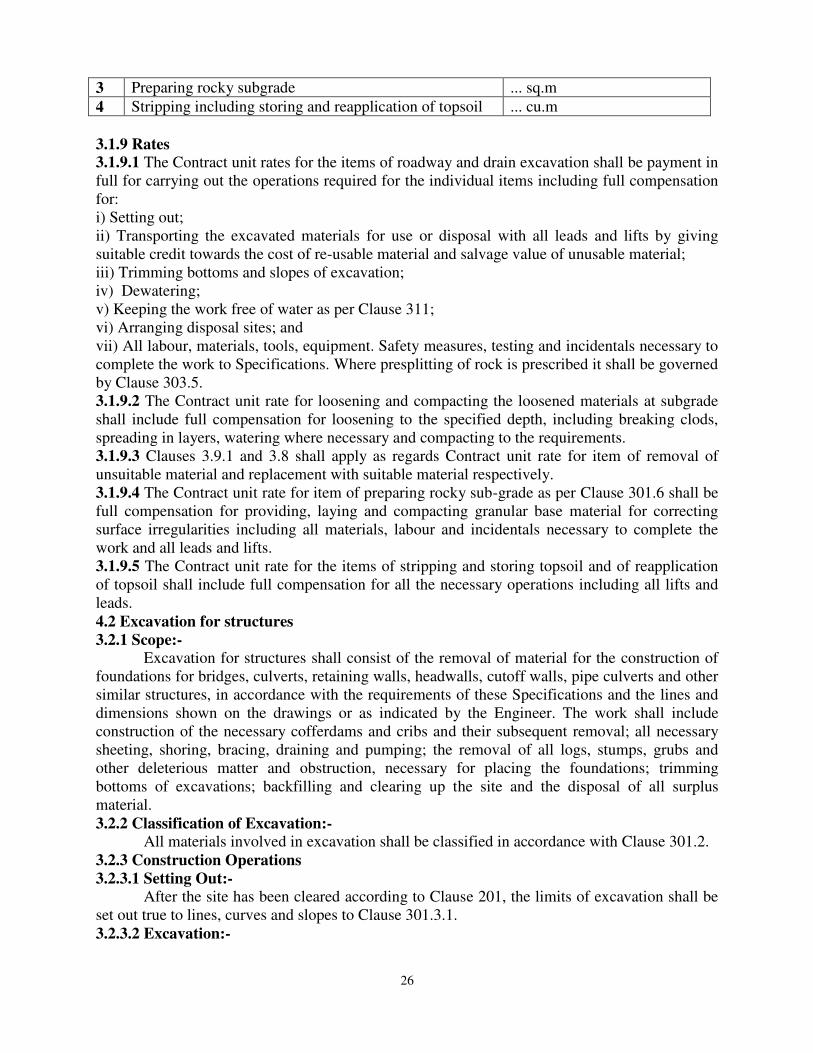
26
3 Preparing rocky subgrade ... sq.m
4 Stripping including storing and reapplication of topsoil ... cu.m
3.1.9 Rates
3.1.9.1 The Contract unit rates for the items of roadway and drain excavation shall be payment in full for carrying out the operations required for the individual items including full compensation for: i) Setting out; ii) Transporting the excavated materials for use or disposal with all leads and lifts by giving suitable credit towards the cost of re-usable material and salvage value of unusable material; iii) Trimming bottoms and slopes of excavation; iv) Dewatering; v) Keeping the work free of water as per Clause 311; vi) Arranging disposal sites; and vii) All labour, materials, tools, equipment. Safety measures, testing and incidentals necessary to complete the work to Specifications. Where presplitting of rock is prescribed it shall be governed by Clause 303.5. 3.1.9.2 The Contract unit rate for loosening and compacting the loosened materials at subgrade shall include full compensation for loosening to the specified depth, including breaking clods, spreading in layers, watering where necessary and compacting to the requirements. 3.1.9.3 Clauses 3.9.1 and 3.8 shall apply as regards Contract unit rate for item of removal of unsuitable material and replacement with suitable material respectively. 3.1.9.4 The Contract unit rate for item of preparing rocky sub-grade as per Clause 301.6 shall be full compensation for providing, laying and compacting granular base material for correcting surface irregularities including all materials, labour and incidentals necessary to complete the work and all leads and lifts. 3.1.9.5 The Contract unit rate for the items of stripping and storing topsoil and of reapplication of topsoil shall include full compensation for all the necessary operations including all lifts and leads. 4.2 Excavation for structures
3.2.1 Scope:-
Excavation for structures shall consist of the removal of material for the construction of foundations for bridges, culverts, retaining walls, headwalls, cutoff walls, pipe culverts and other similar structures, in accordance with the requirements of these Specifications and the lines and dimensions shown on the drawings or as indicated by the Engineer. The work shall include construction of the necessary cofferdams and cribs and their subsequent removal; all necessary sheeting, shoring, bracing, draining and pumping; the removal of all logs, stumps, grubs and other deleterious matter and obstruction, necessary for placing the foundations; trimming bottoms of excavations; backfilling and clearing up the site and the disposal of all surplus material. 3.2.2 Classification of Excavation:-
All materials involved in excavation shall be classified in accordance with Clause 301.2. 3.2.3 Construction Operations
3.2.3.1 Setting Out:-
After the site has been cleared according to Clause 201, the limits of excavation shall be set out true to lines, curves and slopes to Clause 301.3.1. 3.2.3.2 Excavation:-

27
Excavation shall be taken to the width of the lowest step of the footing including additional width as required for construction operation. The sides shall be left plumb where the nature of soil allows it. Where the nature of soil or the depth of the trench and season of the year
do not permit vertical sides, the Contractor at his own cost shall put up necessary shoring, strutting and planking or cut slopes to a safer angle or both with due regard to the safety of personnel and works and to the satisfaction of the Engineer. The depth to which the excavation is to be carried out shall be as shown on the drawings, unless the type of material encountered is such as to require changes, in which case the depth shall be as ordered by the Engineer. Propping shall be undertaken when any foundation or stressed zone from an adjoining structure is within a line of 1 vertical to 2 horizontal from the bottom of the excavation. Where blasting is to be resorted-to, the same shall be carried out in accordance with Clause 302 and all precautions indicated therein observed. Where blasting is likely to endanger adjoining foundations or other structures, necessary precautions such as controlled blasting, providing rubber mat cover to prevent flying of debris etc. shall be taken to prevent any damage. 3.2.3.3 Dewatering and Protection:-
Normally, open foundations shall be laid dry. Where water is met with in excavation due to stream flow, seepage, springs, rain or other reasons, the Contractor shall take adequate
measures such as bailing, pumping, constructing diversion channels, drainage channels, bunds, depression of water level by well-point system, cofferdams and other necessary works to keep the foundation trenches dry when so required and to protect the green concrete/ masonry against damage by erosion or sudden rising of water level. The methods to be adopted in this regard and other details thereof shall be left to the choice of the Contractor but subject to the approval of the Engineer. Approval of the Engineer shall, however, not relieve the Contractor of the responsibility for the adequacy of dewatering and protection arrangements for the quality and safety of the works. Where cofferdams are required, these shall be carried to adequate depths and heights, be safely designed and constructed and be made as watertight as is necessary for facilitating construction to be carried out inside them. The interior dimensions of the cofferdams shall be such as to give sufficient clearance for the construction and inspection and to permit installation of pumping equipment’s, etc., inside the enclosed area. If it is determined beforehand that the foundations cannot be laid dry or the situation is found that the percolation is too heavy for keeping the foundation dry, the foundation concrete shall be laid under water by termite pipe only. In case of flowing water or artesian springs, the flow shall be stopped or reduced as far as possible at the time of placing the concrete. Pumping from the interior of any foundation enclosure shall be done in such a manner as to preclude the possibility of the movement of water through any fresh concrete. No pumping shall be permitted during the placing of concrete and for a period of at least 24 hours thereafter, unless it is done from a suitable sump separated from the concrete work by a watertight wall or other similar means. At the discretion of the Contractor, cement grouting or other approved methods may be used to prevent or reduce seepage and to protect the excavation area. The Contractor shall take all precautions in diverting channels and in discharging the drained water as not to cause damage to the works, crops or any other property. 3.2.3.4 Preparation of Foundation:- The bottom of the foundation shall be levelled both longitudinally and transversely or stepped as directed by the Engineer. Before footing is laid, the surface shall be slightly watered and rammed. In the event of excavation having been made deeper than that shown on the drawings or as otherwise ordered by the Engineer, the extra depth shall be made up with concrete as per Clause 2104.1 at the cost of the Contractor. Ordinary filling shall not be permitted to bring

28
the foundation to the design level as shown in the drawing. When rock or other hard strata is encountered, it shall be freed of all soft and loose material, cleaned and cut to a firm surface either level or stepped as directed by the Engineer. All seams shall be cleaned out and filled with cement mortar or grout to the satisfaction of the Engineer. In the case of excavation in rock, annular space around footing shall be filled with lean concrete M 15 up to the top level of rock. If the depth of fill required is more than 1.5 m in soft rock or 0.6 m in hard rock above the foundation level, the filling up to this level shall be done with M-15 concrete and portion above shall be filled by concrete or by boulders grouted with cement. When foundation piles are used, the excavation for pile cap shall be done after driving/casting of all piles forming the group. After pile driving operations in a given pit are completed, all loose and displaced materials therein shall be removed to the level of the bottom of the pile cap. 3.2.3.5 Slips and Slip-Outs:-
If there are any slips or slip-outs in the excavation, these shall be removed by the Contractor at his own cost. 3.2.3.6 Public Safety:-
Near towns, villages and all frequented places, trenches and foundation pits shall be
securely fenced, provided with proper caution signs and marked with red lights at night to avoid accidents. The Contractor shall take adequate protective measures to see that the excavation operations do not affect or damage adjoining structures. For safety precautions, guidance may be taken from IS: 3764. 3.2.3.7 Backfilling:-
Backfilling shall be done with approved material after concrete or masonry is fully set and carried out in such a way as not to cause undue thrust on any part of the structure. All space
between foundation masonry or concrete and the sides of excavation shall be refilled to the
original surface in layers not exceeding 150 mm compacted thickness. The compaction shall be done with the help of suitable equipment such as trench compactor, mechanical tamper, rammer, plate vibrator etc., after necessary watering, so as to achieve the maximum dry density. 3.2.3.8 Disposal of Surplus Excavated Materials:-
Clause 301.3.11 shall apply (Pl refereed Morth 5th revision). 3.2.3.9 Measurements for Payment:-
Excavation for structures shall be measured in cum for each class of material encountered, limited to the dimensions shown on the drawings or as directed by the Engineer. Excavation over increased width, cutting of slopes, production/support to the existing structures shoring, shuttering and planking shall be deemed as incidental to the main work and shall not be
measured and paid separately. Preparation of rock foundation shall be measured in square meters. 3.4 Borrow Materials:-
The arrangement for the source of supply of the material for embankment and sub-grade and compliance with the guidelines, and environmental requirements, in respect of excavation and borrow areas as stipulated, from time to time by the Ministry of Environment and Forests, Government of India and the local bodies, as applicable shall be the sole responsibility of the Contractor. Borrow pits along the road shall be discouraged. If permitted by the Engineer, these shall not be dug continuously. Ridges of not less than 8 m width should be left at intervals not exceeding 300 m. Small drains shall be cut through the ridges to facilitate drainage. The depth of the pits shall be so regulated that their bottom does not cut an imaginary line having a slope of 1 vertical to 4 horizontal projected from the edge of the final section of the bank, the maximum depth in any case being limited to 1.5 m. Also, no pit shall be dug within the offset width of a

29
minimum of 10m. Haulage of material to embankments or other areas of fill shall proceed only when sufficient spreading and compaction plant is operating at the place of deposition. Where the excavation reveals a combination of acceptable and unacceptable materials, the Contractor shall, unless otherwise agreed by the Engineer, carry out the excavation in such a manner that the acceptable materials are excavated separately for use in the permanent works without contamination by the unacceptable materials. The acceptable materials shall be stockpiled separately. The Contractor shall ensure that he does not adversely affect the stability of excavation or fills by the methods of stockpiling materials, use of plants or siting of temporary buildings or structures. 3.4.1 Compaction Requirements
The Contractor shall obtain representative samples from each of the identified borrow areas and have these tested at the site laboratory following a testing programme approved by the Engineer. It shall be ensured that the subgrade material when compacted to the density requirements as in Table 300-2 shall yield the specified design CBR value of the sub-grade.
Table 300-2: Compaction Requirements for Embankment and Sub-grade
Type of work/material Relative compaction as % of max. laboratory dry density as per 15:2720 (Part 8)
Subgrade and earthen shoulders Not less than 97%
Embankment, Not less than 95%
Expansive Clays a) Subgrade and 500 mm portion just below the subgrade
b) Remaining portion of embankment
Not allowed
90-95%
The Contractor shall at least 7 working days before commencement of compaction submit the following to the Engineer for approval: i) The values of maximum dry density and optimum moisture content obtained in accordance with 18:2720 (Part 8), appropriate for each of the fill materials he intends to use. ii) A graph of dry density plotted against moisture content from which each of the values in (i) above of maximum dry density and optimum moisture content were determined. The maximum dry density and optimum moisture content approved by the Engineer shall form the basis for compaction. 3.5 SURFACE/SUB-SURFACE DRAINS
3.5.1 Scope:-
The work shall consist of constructing surface and/or sub-surface drains in accordance with the requirements of these Specifications and to the lines, grades, dimensions and other particulars shown on the drawings or as directed by the Engineer. Schedule of work shall be so arranged that the drains are completed in proper sequence with road works to ensure that no excavation of the completed road works is necessary subsequently or any damage is caused to these works due to lack of drainage. 3.5.2 Surface Drains:-
Surface drains shall be excavated to the specified lines, grades, levels and dimensions to
the requirements of Clause 301. The excavated material shall be removed from the area
adjoining the drains and if found suitable, utilized in embankment/sub-grade construction. All
unsuitable material shall be disposed of as directed. The excavated bed and sides of the drains
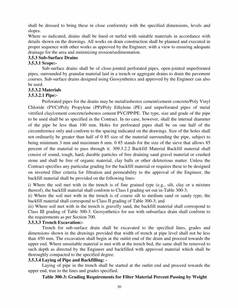
30
shall be dressed to bring these in close conformity with the specified dimensions, levels and slopes. Where so indicated, drains shall be lined or turfed with suitable materials in accordance with details shown on the drawings. All works on drain construction shall be planned and executed in proper sequence with other works as approved by the Engineer, with a view to ensuring adequate drainage for the area and minimizing erosion/sedimentation. 3.5.3 Sub-Surface Drains
3.5.3.1 Scope:-
Sub-surface drains shall be of close-jointed perforated pipes, open-jointed unperforated pipes, surrounded by granular material laid in a trench or aggregate drains to drain the pavement courses. Sub-surface drains designed using Geosynthetics and approved by the Engineer can also be used. 3.5.3.2 Materials
3.5.3.2.1 Pipe:-
Perforated pipes for the drains may be metal/asbestos cement/cement concrete/Poly Vinyl
Chloride (PVC)/Poly Propylene (PP)/Poly Ethylene (PE) and unperforated pipes of metal
vitrified clay/cement concrete/asbestos cement PVC/PP/PE. The type, size and grade of the pipe
to be used shall be as specified in the Contract. In no case, however, shall the internal diameter
of the pipe be less than 100 mm. Holes for perforated pipes shall be on one half of the
circumference only and conform to the spacing indicated on the drawings. Size of the holes shall
not ordinarily be greater than half of 0 85 size of the material surrounding the pipe, subject to
being minimum 3 mm and maximum 6 mm. 0 85 stands for the size of the sieve that allows 85
percent of the material to pass through it. 309.3.2.2 Backfill Material Backfill material shall
consist of sound, tough, hard, durable particles of free draining sand gravel material or crushed
stone and shall be free of organic material, clay balls or other deleterious matter. Unless the
Contract specifies any particular grading for the backfill material or requires these to be designed
on inverted filter criteria for filtration and permeability to the approval of the Engineer, the
backfill material shall be provided on the following lines:
i) Where the soil met with in the trench is of fine grained type (e.g., silt, clay or a mixture thereof), the backfill material shall conform to Class I grading set out in-Table 300-3; ii) Where the soil met with in the trench is of course silt to medium sand or sandy type, the backfill material shall correspond to Class II grading of Table 300-3; and iii) Where soil met with in the trench is gravelly sand, the backfill material shall correspond to Class III grading of Table 300-3. Geosynthetics for use with subsurface drain shall conform to the requirements as per Section 700. 3.5.3.3 Trench Excavation:-
Trench for sub-surface drain shall be excavated to the specified lines, grades and dimensions shown in the drawings provided that width of trench at pipe level shall not be less than 450 mm. The excavation shall begin at the outlet end of the drain and proceed towards the upper end. Where unsuitable material is met with at the trench bed, the same shall be removed to
such depth as directed by the Engineer and backfilled with approved material which shall be
thoroughly compacted to the specified degree. 3.5.3.4 Laying of Pipe and Backfilling: -
Laying of pipe in the trench shall be started at the outlet end and proceed towards the upper end, true to the lines and grades specified.
Table 300-3: Grading Requirements for Filter Material Percent Passing by Weight

31
Sieve Class 1 Class 2 Class 3
53 mm 100
45 mm 97-100
26.5 mm 100
22.4 mm 95-100 58-100
11.2 mm 100 48-100 20-60
5.6 mm 92-100 28-54 4-32
2.8 mm 83-100 20-35 0-10
1.4 mm 59-96 0-5
710 micron 35-80 6-18
355 micron 14-40 2-9
180 micron 3-15
90 micron 0-5 0-4 0-3
Before placing the pipe, backfill material of the required grading(s) shall be laid for full width of the trench bed and compacted to a minimum thickness of 150 mm or as shown on the drawings. The thickness of the backfill material on the sides of the pipe shall be as shown on the drawings subject to a minimum of 150 mm. The pipe shall then be embedded firmly on the bed. Perforated pipes, unless otherwise specified, shall be placed with their perforations down to minimize clogging. The pipe sections shall be joined securely with appropriate coupling fittings or bands. Non-perforated pipes shall be laid with joints as close as possible with the open joints wrapped with suitable pervious material (like suitable Geosynthetics of not less than 150 mm width) to permit entry of water but prevent fines entering the pipes. In the case of non-perforated pipes with bell end, the bell shall face upgrade. Upgrade end sections of the pipe installation shall be tightly closed by means of concrete plugs or plugs fabricated from the same material as the pipe and securely held in place to prevent entry of soil materials. After the pipe installation has been completed and approved, backfill material of the required grading (s) (see Clause 309.3.2.2) shall be placed over the pipe to the required level in horizontal layers not exceeding 150 mm in thickness and thoroughly compacted. The minimum thickness of material above the top of the pipe shall be 300 mm. unless otherwise provided, sub-surface drains not located below the road pavement shall be sealed at the top by means of 150 mm thick layer of compacted clay so as to prevent percolation of surface water. 3.5.3.4 Measurements for Payment:-
Measurement for surface and sub-surface drains shall be per running meter length of the
drain. 3.5.3.5 Rates:-
The Contract unit rates for surface and sub-surface drains shall be payment in full for all items such as excavation, dressing the sides and bottom; providing lining, turning, pitching, masonry, concrete and plastering; providing, laying and jointing pipes including wrapping with Geosynthetics fabric; providing, laying and compacting backfill around the pipe, granular
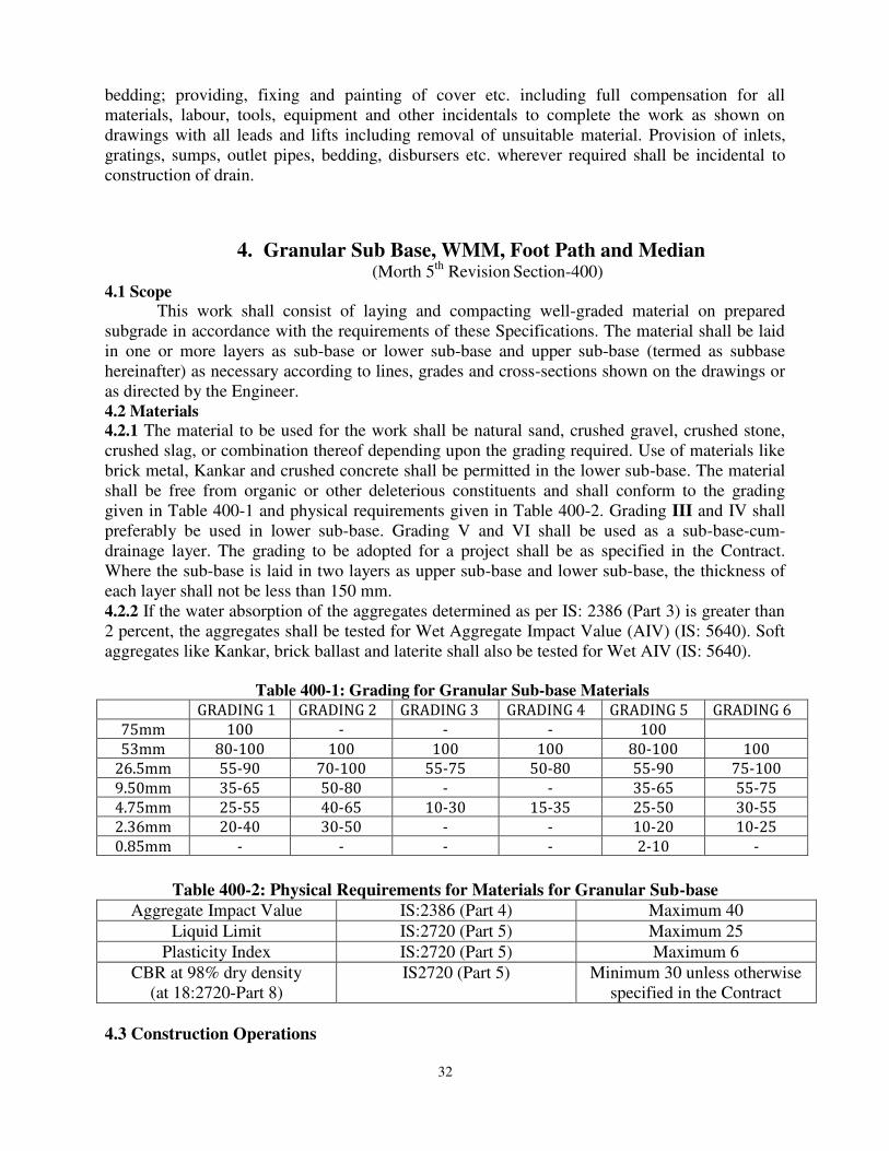
32
bedding; providing, fixing and painting of cover etc. including full compensation for all materials, labour, tools, equipment and other incidentals to complete the work as shown on
drawings with all leads and lifts including removal of unsuitable material. Provision of inlets, gratings, sumps, outlet pipes, bedding, disbursers etc. wherever required shall be incidental to construction of drain.
4. Granular Sub Base, WMM, Foot Path and Median (Morth 5th Revision Section-400)
4.1 Scope
This work shall consist of laying and compacting well-graded material on prepared subgrade in accordance with the requirements of these Specifications. The material shall be laid in one or more layers as sub-base or lower sub-base and upper sub-base (termed as subbase hereinafter) as necessary according to lines, grades and cross-sections shown on the drawings or as directed by the Engineer. 4.2 Materials
4.2.1 The material to be used for the work shall be natural sand, crushed gravel, crushed stone, crushed slag, or combination thereof depending upon the grading required. Use of materials like brick metal, Kankar and crushed concrete shall be permitted in the lower sub-base. The material shall be free from organic or other deleterious constituents and shall conform to the grading given in Table 400-1 and physical requirements given in Table 400-2. Grading III and IV shall preferably be used in lower sub-base. Grading V and VI shall be used as a sub-base-cum-drainage layer. The grading to be adopted for a project shall be as specified in the Contract. Where the sub-base is laid in two layers as upper sub-base and lower sub-base, the thickness of each layer shall not be less than 150 mm. 4.2.2 If the water absorption of the aggregates determined as per IS: 2386 (Part 3) is greater than 2 percent, the aggregates shall be tested for Wet Aggregate Impact Value (AIV) (IS: 5640). Soft aggregates like Kankar, brick ballast and laterite shall also be tested for Wet AIV (IS: 5640).
Table 400-1: Grading for Granular Sub-base Materials
GRADING 1 GRADING 2 GRADING 3 GRADING 4 GRADING 5 GRADING 6
75mm 100 - - - 100
53mm 80-100 100 100 100 80-100 100
26.5mm 55-90 70-100 55-75 50-80 55-90 75-100
9.50mm 35-65 50-80 - - 35-65 55-75
4.75mm 25-55 40-65 10-30 15-35 25-50 30-55
2.36mm 20-40 30-50 - - 10-20 10-25
0.85mm - - - - 2-10 -
Table 400-2: Physical Requirements for Materials for Granular Sub-base
Aggregate Impact Value IS:2386 (Part 4) Maximum 40
Liquid Limit IS:2720 (Part 5) Maximum 25
Plasticity Index IS:2720 (Part 5) Maximum 6
CBR at 98% dry density (at 18:2720-Part 8)
IS2720 (Part 5) Minimum 30 unless otherwise specified in the Contract
4.3 Construction Operations
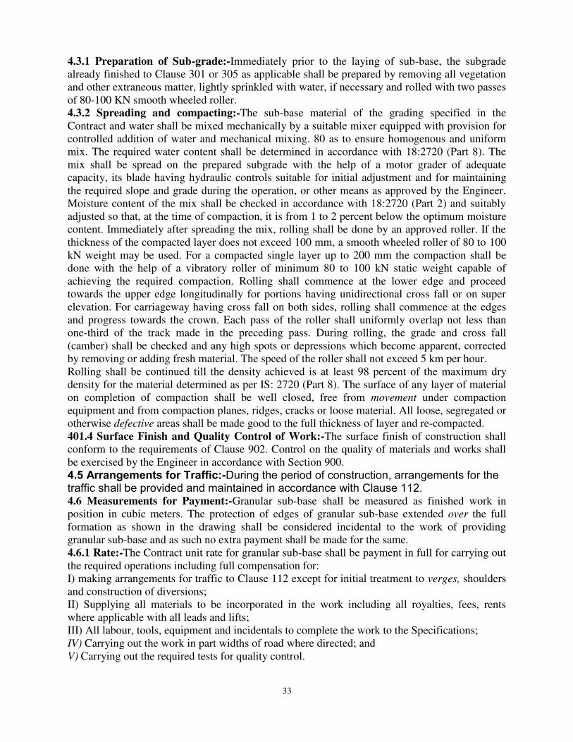
33
4.3.1 Preparation of Sub-grade:-Immediately prior to the laying of sub-base, the subgrade already finished to Clause 301 or 305 as applicable shall be prepared by removing all vegetation and other extraneous matter, lightly sprinkled with water, if necessary and rolled with two passes of 80-100 KN smooth wheeled roller. 4.3.2 Spreading and compacting:-The sub-base material of the grading specified in the Contract and water shall be mixed mechanically by a suitable mixer equipped with provision for controlled addition of water and mechanical mixing. 80 as to ensure homogenous and uniform mix. The required water content shall be determined in accordance with 18:2720 (Part 8). The mix shall be spread on the prepared subgrade with the help of a motor grader of adequate capacity, its blade having hydraulic controls suitable for initial adjustment and for maintaining the required slope and grade during the operation, or other means as approved by the Engineer. Moisture content of the mix shall be checked in accordance with 18:2720 (Part 2) and suitably
adjusted so that, at the time of compaction, it is from 1 to 2 percent below the optimum moisture content. Immediately after spreading the mix, rolling shall be done by an approved roller. If the
thickness of the compacted layer does not exceed 100 mm, a smooth wheeled roller of 80 to 100 kN weight may be used. For a compacted single layer up to 200 mm the compaction shall be done with the help of a vibratory roller of minimum 80 to 100 kN static weight capable of achieving the required compaction. Rolling shall commence at the lower edge and proceed
towards the upper edge longitudinally for portions having unidirectional cross fall or on super elevation. For carriageway having cross fall on both sides, rolling shall commence at the edges and progress towards the crown. Each pass of the roller shall uniformly overlap not less than one-third of the track made in the preceding pass. During rolling, the grade and cross fall (camber) shall be checked and any high spots or depressions which become apparent, corrected by removing or adding fresh material. The speed of the roller shall not exceed 5 km per hour. Rolling shall be continued till the density achieved is at least 98 percent of the maximum dry density for the material determined as per IS: 2720 (Part 8). The surface of any layer of material on completion of compaction shall be well closed, free from movement under compaction equipment and from compaction planes, ridges, cracks or loose material. All loose, segregated or otherwise defective areas shall be made good to the full thickness of layer and re-compacted. 401.4 Surface Finish and Quality Control of Work:-The surface finish of construction shall conform to the requirements of Clause 902. Control on the quality of materials and works shall be exercised by the Engineer in accordance with Section 900. 4.5 Arrangements for Traffic:-During the period of construction, arrangements for the traffic shall be provided and maintained in accordance with Clause 112. 4.6 Measurements for Payment:-Granular sub-base shall be measured as finished work in position in cubic meters. The protection of edges of granular sub-base extended over the full formation as shown in the drawing shall be considered incidental to the work of providing granular sub-base and as such no extra payment shall be made for the same. 4.6.1 Rate:-The Contract unit rate for granular sub-base shall be payment in full for carrying out the required operations including full compensation for: I) making arrangements for traffic to Clause 112 except for initial treatment to verges, shoulders and construction of diversions; II) Supplying all materials to be incorporated in the work including all royalties, fees, rents where applicable with all leads and lifts; III) All labour, tools, equipment and incidentals to complete the work to the Specifications; IV) Carrying out the work in part widths of road where directed; and V) Carrying out the required tests for quality control.
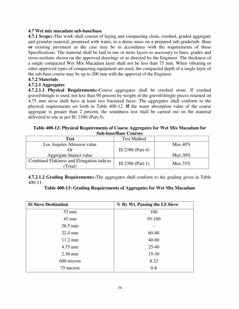
34
4.7 Wet mix macadam sub-base/base
4.7.1 Scope:-This work shall consist of laying and compacting clean, crushed, graded aggregate and granular material, premixed with water, to a dense mass on a prepared sub-grade/sub- Base or existing pavement as the case may be in accordance with the requirements of these
Specifications. The material shall be laid in one or more layers as necessary to lines, grades and cross-sections shown on the approved drawings or as directed by the Engineer. The thickness of a single compacted Wet Mix Macadam layer shall not be less than 75 mm. When vibrating or other approved types of compacting equipment are used, the compacted depth of a single layer of the sub-base course may be up to 200 mm with the approval of the Engineer. 4.7.2 Materials
4.7.2.1 Aggregates
4.7.2.1.1 Physical Requirements:-Course aggregates shall be crushed stone. If crushed gravel/shingle is used, not less than 90 percent by weight of the gravel/shingle pieces retained on 4.75 mm sieve shall have at least two fractured faces. The aggregates shall conform to the physical requirements set forth in Table 400-12. If the water absorption value of the coarse aggregate is greater than 2 percent, the soundness test shall be carried out on the material delivered to site as per IS: 2386 (Part-5).
Table 400-12: Physical Requirements of Coarse Aggregates for Wet Mix Macadam for
Sub-base/Base Courses
Test Test Method Los Angeles Abrasion value
Or Aggregate Impact value
IS:2386 (Part-4) Max.40%
Max.30%
Combined Flakiness and Elongation indices (Total)
IS:2386 (Part-1) Max.35%
4.7.2.1.2 Grading Requirements:-The aggregates shall conform to the grading given in Table 400-13.
Table 400-13: Grading Requirements of Aggregates for Wet Mix Macadam
IS Sieve Destination % By Wt. Passing the I.S Sieve
53 mm
45 mm
26.5 mm
22.4 mm
11.2 mm
4.75 mm
2.36 mm
600 micron
75 micron
100
95-100
-
60-80
40-60
25-40
15-30
8.22
0-8

35
Material finer than 425 micron shall have Plasticity Index (PI) not exceeding 6. The final gradation approved within these limits shall be graded from coarse to fine and shall not vary from the low limit on one sieve to the high limit on the adjacent sieve or vice versa.
4.7.3 Construction Operations
4.7.3.1 Preparation of Base:-Clause 404.3.1 shall apply. 4.7.3.2 Provision of Lateral Confinement of Aggregates:-While constructing wet mix macadam, arrangement shall be made for the lateral confinement of wet mix. This shall be done by laying materials in adjoining shoulders along with that of wet mix macadam layer and following the sequence of operations described in Clause 404.3.3. 4.7.3.3 Preparation of Mix:-Wet Mix Macadam shall be prepared in an approved mixing plant of suitable capacity having provision for controlled addition of water and forced/ positive mixing arrangement like pug mill or pan type mixer of concrete batching plant. The plant shall have following features: i) For feeding aggregates- three/ four bin feeders with variable speed motor ii) Vibrating screen for removal of oversize aggregates iii) Conveyor Belt iv) Controlled system for addition of water v) Forced/positive mixing arrangement like pug-mill or pan type mixer vi) Centralized control panel for sequential operation of various devices and precise process control vii) Safety devices Optimum moisture for mixing shall be determined in accordance with IS: 2720 (Part-8) after replacing the aggregate fraction retained on 22.4 mm sieve with material of 4.75 mm to 22.4 mm size. While adding water, due allowance should be made for evaporation losses. However, at the time of compaction, water in the wet mix should not vary from the optimum value by more than agreed limits. The mixed material should be uniformly wet and no segregation should be permitted. 4.7.3.4 Spreading of Mix:-Immediately after mixing, the aggregates shall be spread uniformly and evenly upon the prepared sub-grade/sub-base/base in required quantities. In no case shall these be dumped in heaps directly on the area where these are to be laid nor shall their hauling over a partly completed stretch be permitted. The mix may be spread by a paver finisher. The paver finisher shall be self-propelled of adequate capacity with following features: i) Loading hoppers and suitable distribution system, so as to provide a smooth uninterrupted material flow for different layer thicknesses from the tipper to the screed. ii) Hydraulically operated telescopic screed for paving width upto to 8.5 m and fixed screed beyond this. The screed shall have tamping and vibrating arrangement for initial compaction of the layer. iii) Automatic levelling control system with electronic sensing device to maintain mat thickness and cross slope of mat during laying procedure. In exceptional cases where it is not possible for the paver to be utilized, mechanical means like motor grader may be used with the prior approval of the Engineer. The motor grader shall be capable of spreading the material uniformly all over the surface. The surface of the aggregate shall be carefully checked with templates and all high or low spots remedied by removing or adding aggregate as may be required. The layer may be tested by depth blocks during construction. No segregation of larger and fine particles should be allowed. The aggregates as spread should be of uniform gradation with no pockets of fine materials.
36
The Engineer may permit manual mixing and lor laying of wet mix macadam where small quantity of wet mix macadam is to be executed. Manual mixing/laying in inaccessible/ remote locations and in situations where use of machinery is not feasible can also be permitted. Where manual mixing/laying is intended to be used, the same shall be done with the approval of the Engineer. 4.7.3.5 Compaction:-After the mix has been laid to the required thickness, grade and cross fall/camber the same shall be uniformly compacted to the full depth with suitable roller. If the thickness of single compacted layer does not exceed 100 mm, a smooth wheel roller of 80 to 100kN weight may be used. For a compacted single layer upto 200 mm, the compaction shall be done with the help of vibratory roller of minimum static weight of 80 to 100 kN with an arrangement for adjusting the frequency and amplitude. An appropriate frequency and amplitude may be selected. The speed of the roller shall not exceed 5 km/h. In portions having unidirectional cross fall/super elevation, rolling shall commence from the lower edge and progress gradually towards the upper edge. Thereafter, roller should progress parallel to the center line of the road, uniformly over-lapping each preceding track by at least one-third width until the entire surface has been rolled. Alternate trips of the roller shall be terminated in stops at least 1 m away from any preceding stop. In portions in camber, rolling should begin at the edge with the roller running forward and backward until the edges have been firmly compacted. The roller shall then progress gradually towards the center parallel to the center line of the road uniformly overlapping each of the preceding track by at least one-third width until the entire surface has been rolled. Any displacement occurring as a result of reversing of the direction of a roller or from any other cause shall be corrected at once as specified and/or removed and made good. Along forms, kerbs, walls or other places not accessible to the roller, the mixture shall be thoroughly compacted with mechanical tampers or a plate compactor. Skin patching of an area without scarifying the surface to permit proper bonding of the added material shall not be permitted. Rolling should not be done when the sub-grade is soft or yielding or when it causes a wavelike motion in the sub-base/base course or sub-grade. If irregularities develop during rolling which exceed 12 mm when tested with a 3 m straight edge, the surface should be loosened and premixed material added or removed as required before rolling again so as to achieve a uniform surface conforming to the desired grade and crossfall. In no case shall the use of unmixed material be permitted to make up the depressions. Rolling shall be continued till the density achieved is at least 98 percent of the maximum dry density for the material as determined by the method outlined in IS:2720 (Part-8). After completion, the surface of any finished layer shall be well-closed, free from movement under compaction equipment or any compaction planes, ridges, cracks and loose material. All loose, segregated or otherwise defective areas shall be made good to the full thickness of the layer and re-compacted. 4.7.3.6 Setting and drying:-After final compaction of wet mix macadam course, the road shall be allowed to dry for 24 hours. 4.8 Opening to Traffic:-No vehicular traffic shall be allowed on the finished wet mix macadam surface. Construction equipment may be allowed with the approval of the Engineer. 4.8 Surface Finish and Quality Control of Work
4.8.1 Surface Evenness
The surface finish of construction shall conform to the requirements of Clause 902. 4.8.2 Quality Control
Control on the quality of materials and works shall be exercised by the Engineer in accordance with Section 900.

37
4.9 Rectification of Surface Irregularity:-Where the surface irregularity of the wet mix macadam course exceeds the permissible tolerances or where the course is otherwise defective due to sub-grade soil getting mixed with the aggregates, the full thickness of the layer shall be scarified over the affected area, re-shaped with added premixed material or removed and replaced with fresh premixed material as applicable and re-compacted in accordance with Clause 406.3. The area treated in the aforesaid manner shall not be less than 5 m long and 2 m wide. In no case shall depressions be filled up with unmixed and ungraded material or fines. 4.10 Arrangement for Traffic:-During the period of construction, arrangements for traffic shall be done as per Clause 112. 4.11 Measurements for Payment:-Wet mix macadam shall be measured as finished work in position in cubic meters. 4.12 Rate:-The Contract unit rate for wet mix macadam shall be payment in full for carrying out the required operations including full compensation for all components listed in Clause 401.7. 4.13 SHOULDERS, ISLANDS AND MEDIANS
4.13.1 Scope:-The work shall consist of constructing shoulder (hard/paved/earthen with brick or stone block edging) on either side of the pavement, median in the road dividing the carriageway into separate lanes and islands for channelizing the traffic at junctions in accordance with the
requirements of these Specifications and in conformity with the lines, grades and cross-sections
shown on the drawings or as directed by the Engineer. 4.13.2 Materials:-Shoulder on either side of the road may be of selected earth/granular material/paved conforming to the requirements of Clause 305/401 and the median may be of selected earth conforming to the requirements of Clause 305. Median Traffic islands shall be raised and kerbed at the perimeter and the enclosed area filled with earth and suitably covered with grass turf/shrubs as per Clause 307 and/or paved as per Clauses 410.3.4 or 41 0.3.5. Paved shoulders shall consist of sub-base, base and surfacing courses, as shown in the drawings and materials for the same shall conform to relevant Specifications of the corresponding items. Where paved or hard shoulders are not provided, the pavement shall be provided with brick/stone block edgings as shown in the drawings. The brick shall conform to Clause 1003 of these Specifications. Stone blocks shall conform to Clause 1004 of these Specifications and shall be of size 225 mm x 110 mm x 75 mm. 4.13.3 Size of Shoulders/Medians/Islands:-Shoulder (earthen/hard/paved)/median/traffic island dimensions shall be as shown on the drawings or as directed by the Engineer. 408.4 Construction Operations
4.13.4.1 Shoulders:-The sequence of operations shall be such that the construction of paved shoulder is done in layers each matching the thickness of adjoining pavement layer. Only after a layer of pavement and corresponding layers in paved and earth shoulder portion have been laid and compacted, the construction of next layer of pavement and shoulder shall be taken up. Where the materials in adjacent layers are different, these shall be laid together and the pavement layer shall be compacted first. The corresponding layer in paved shoulder portion shall be compacted thereafter, which shall be followed by compaction of each shoulder layer. The adjacent layers having same material shall be laid and compacted together. In all cases where paved shoulders have to be provided alongside of existing carriageway, the existing shoulders shall be excavated in full width and to the required depth as per Clause 301.3.7. Under no circumstances, box cutting shall be done for construction of shoulders. Compaction requirement of earthen shoulder shall be as per Table 300-3. In the case of bituminous courses and concrete pavement, work on shoulder shall start only after the pavement course has been laid and compacted. During all stages of shoulder construction, the required
38
cross fall shall be maintained to drain off surface water. Regardless of the method of laying, all shoulder construction material shall be placed directly on the shoulder. Any spilled material dragged on to the pavement surface shall be immediately removed, without damage to the pavement, and the area so affected thoroughly cleaned. 4.13.4.2 Median and Islands:-Median and islands shall be constructed in a manner similar to shoulder up to the road level. Thereafter, the median and islands, if raised, shall be raised at least 300 mm by using kerbs stones of approved material and dimensions and suitably finished and painted as directed by the Engineer. If not raised, the median and islands shall be differentiated from the shoulder/ pavement as the case may be, as directed by the Engineer. The confined area of the median and islands shall be filled with local earth or granular material or any other approved material and compacted by plate compactor/power rammer. The confined area after filling with earth shall be turfed with grass or planted with shrubs, or finished with tiles/slabs as provided in the drawings. 4.13.4.3 Brick/Stone Block Edging:-The brick/stone blocks shall be laid on edge, with the length parallel to the transverse direction of the road. They shall be laid on a bed of 25 mm sand, set carefully rolled into position by a light roller and made flush with the finished level of the pavement. 4.13.5 Surface Finish and Quality Control of Works:-The surface finish of construction shall conform to the requirements of Clause 902. Control on the quality of materials and works shall be exercised by the Engineer in accordance with Section 900. 4.13.6 Measurements for Payment:-Shoulder (earthen/hard/paved), island and median construction shall be measured as finished work in position as below: i) For excavation in cum. ii) For earthwork/granular fill in cum. iii) For sub-base, base, surfacing courses in units as for respective items iv) For kerbs in running meter; length of kerbs for median shall be measured for each side separately. v) For turfing, shrubs and tile/slab finish in sq.m. vi) For brick/stone block edging in running meter, the length for brick/ stone block edging for median edging shall be measured for each side separately. 4.13.7 Rate:-The Contract unit rate for shoulder (hard/paved/earthen with brick or stone block edging), island and median construction shall be payment in full for carrying out the required operations including full compensation for all components listed in Clause 401.7 (i) to (v) as applicable. The rate for brick/stone block edging shall include the cost of sand cushion.
4.14 CEMENT CONCRETE KERB AND KERB WITH CHANNEL
4.14.1 Scope:-This work shall consist of constructing cement concrete kerbs and kerbs with channel in the central median and/or along the footpaths or separators in conformity with the lines, levels and dimensions as specified in the drawings or as directed by the Engineer. 4.14.2 Materials:-Kerbs and kerbs with channel shall be provided in cement concrete of Grade M 20 in accordance with Section 1700 of these Specifications. 4.14.3 Type of Construction:-These shall be cast-in-situ construction with suitable kerb casting machine in all situations except at locations where continuous casting with equipment is not practicable. In those locations precast concrete blocks shall be used.
39
4.14.4 Equipment:-A continuous kerbs casting equipment of adequate capacity and controls, capable of laying the kerbs in required cross-sections and producing a well-compacted mass of concrete free of voids and honeycombs, shall be used. 4.14.5 Construction Operations
4.14.5.1 Kerbs shall be laid on firm foundation of minimum 150 mm thickness of cement concrete of M 15 grade cast in-situ or on extended width of pavement. The foundation shall have a projection of 50 mm beyond the kerbs stone. Before laying the foundation of lean concrete, the base shall be leveled and slightly watered to make it damp. 4.14.5.2 In the median portions in the straight reaches, the kerbs shall be cast in continuous lengths. In the portions where footpath is provided and/or the slope of the carriageway is towards median (as in case of super elevated portion), there shall be sufficient gap/recess left in the kerbs to facilitate drainage openings. 4.14.5.3 After laying the kerbs and just prior to hardening of the concrete, saw cut grooves shall be provided at 5 m intervals up to finished road level or as specified by the Engineer. 4.14.5.4 Kerbs on the drainage ends such as along the footpath or the median in super elevated portions, shall be cast with monolithic concrete channels as indicated in drawings. The slope of the channel towards drainage pipes shall be ensured for efficient drainage of the road surface. 4.14.5.5 Vertical and horizontal tolerances with respect to true line and level shall be ±6mm. 4.14.6 Measurements for Payment:-Cement concrete kerbs with channel including foundation shall be measured in linear meter for the complete item of work. 4.14..7 Rate:-The Contract unit rates for cement concrete kerbs with channel including foundation for kerbs shall be payment in full compensation for furnishing all materials, labour, tools, equipment for construction and other incidental cost necessary to complete the work. 4.15 FOOTPATHS AND SEPARATORS
4.15.1 Scope:-The work shall consist of constructing footpaths and/or separators at locations as specified in the drawings or as directed by the Engineer. The lines, levels and dimensions shall be as per the drawings. The scope of the work shall include provision of all drainage arrangements as shown in the drawings or as directed by the Engineer. 4.15.2 Materials:-The footpaths and separators shall be constructed with any of the following types: a) Cast-in-situ cement concrete of Grade M 20 as per Section 1700 of the Specifications. The minimum size of the panels shall be as specified in the drawings. b) Precast cement concrete blocks and interlocking blocks/tiles of grade not less than M 30 as per Section 1700 of the Specifications. The thickness and size of the cement concrete blocks or interlocking blocks/ tiles shall be as specified in the drawings. c) Natural stone slab cut and dressed from stone of good and sound quality, uniform in texture, free from defects and at least equal to a sample submitted by the Contractor and approved by the Engineer. The thickness and size of the natural stone slab shall be as specified in the drawings. 4.15.3 Construction Operations
4.15.3.1 Drainage pipes below the footpath originating from the kerbs shall be first laid in the required slope and connected to the drains/sumps/storm water drain/drainage chutes as per provisions of the drawings, or as specified. 4.15.3.2 Portion on back side of kerbs shall be filled and compacted with granular sub-base material as per Clause 401 of the Specifications in specified thickness. 4.15.3.3 The base for cast-in-situ cement concrete panels/ tiles/ nature stone slab shall be prepared and finished to the required lines, levels and dimensions as indicated in the drawings.

40
Over the prepared base, precast concrete interlocking blocks/tiles/natural stone slabs and/or cast-in- situ slab shall be set/laid as described in Clauses 410.3.4 and 410.3.5. 4.15.3.4 Tiles/Natural Stone Slabs:-The blocks/tiles/slabs shall be set on a layer of average 12 mm thick cement-sand mortar (1:3) laid on prepared base in such a way that there is no rocking. The gaps between the blocks/tiles/slabs shall not be more than 12 mm and shall be filled with cement-sand mortar (1:3). 4.15.3.5 Cast-in-Situ Cement Concrete:-The panels of specified size shall be cast on the prepared base in panels of specified size in a staggered manner. Construction joints shall be provided as per Section 1700 of the Specifications. 4.15.3.6 Precast Concrete Blocks and Interlocking Concrete Block Pavements the precast concrete blocks and interlocking concrete block pavement shall be laid on a Bedding of sand of thickness specified in the drawing. The grading of the sand layer shall be as in Table 400-16 in Morth 5th revision Section 400 (Page No.145). The joints shall be filled with sand passing a 2.35 mm size with the grading as in Table 400-17 in Morth 5th revision Section 400 (Page No.145). The bedding sand slightly moist, the moisture content being about 4 percent. The bedding sand shall be compacted by vibratory plate compactor. The blocks shall be laid to the levels indicated on the drawings and to the pattern directed by the Engineer. The surface tolerance shall be ±10 mm with respect to the design level. The blocks shall be embedded using a hammer. 4.15.4, Measurements for Payment:-Footpaths and separators shall be measured in Sq.m between inside of kerbs. The edge restraint block and kerbs shall be measured separately in linear meter. The items pertaining to drainage shall be measured separately. 4.15.5 Rate:-Contract unit rates shall be inclusive of full compensation for all labour, materials, tools, equipment for footpaths including the base. Cost of providing pipes and arrangement for their discharge into appropriate drainage channels shall be incidental to the construction of footpaths.
5. Prime Coat, Tact coat, Dense Bituminous Macadam
And
Bituminous Concrete
(Morth 5th Revision Section-500) 5.1 GENERAL REQUIREMENTS FOR BITUMINOUS PAVEMENT LAYERS
5.1.1 General:-
Bituminous pavement courses shall be made using the materials described in the
Specifications. The use of machinery and equipment mentioned in various Clauses of these Specifications is mandatory. Details of the machinery and equipment are available in the Manual for Construction and Supervision of Bituminous Works. The equipment mandatory for any particular project shall be in accordance with the Contract Specifications for that project. 5.1.2 Materials
5.1.2.1 Binder:-
The binder shall be an appropriate type of bituminous material complying with the relevant Indian Standard, as defined in the appropriate Clauses of these Specifications, or as
otherwise specified herein. The choice of binder shall be stipulated in the Contract or by the Engineer. Where viscosity grades of bitumen are specified, they are referred to by a designation in accordance with IS: 73. Where modified bitumen is specified, it shall conform to the requirements of IRC: SP: 53 and IS: 15462; and the following provision of this Specification shall apply.

41
i) Modified bitumen from refinery sources or blended at approved central plant or at site using appropriate industrial process and plant with high shear mill, and testing facilities to achieve stable and homogenous mix shall be used. The use of high shear mixer or any other device capable of producing a homogeneous blend is essential when the modifier is in powder form. ii) Transportation tanks and storage tanks shall be insulated and equipped with effective heating system and circulation! Agitating device to maintain the specified temperature, homogeneity and viscosity of the bitumen during transit and storage. iii) Separation, difference in softening point (R&B), shall not be more than 3°C for any type of specified modified bitumen when tested as per Annex B of IS: 15462. Selection criteria for viscosity grade bitumen, based on highest and lowest daily mean temperatures at a particular site, are given in Table 500-1. Selection criteria for modified bitumen shall be in accordance with IRC: SP:53. 501.2.2 Coarse Aggregates The coarse aggregates shall consist of crushed rock, crushed gravel or other hard material retained on the 2.36 mm sieve. They shall be clean, hard, and durable, of cubical shape, free from dust and soft or friable matter, organic or other deleterious matter. Where the Contractor's selected source of aggregates has poor affinity for bitumen, the Contractor shall demonstrate through test results that with the use of anti-stripping agents, the stripping value is improved to satisfy the specification requirements. The Engineer may approve such a source and, as a condition for the approval of that source, the bitumen shall be treated with approved antistripping agents, as per the manufacturer's recommendations, at the cost of the Contractor. Where crushed gravel is proposed for use as aggregate not less than 90 percent by weight of the crushed material retained on the 4.75 mm sieve shall have at least two fractured faces, except that in the case of bituminous concrete the requirement in this regard shall be 95 percent. The aggregates shall satisfy the physical requirements set forth in the individual relevant clause for the material. 5.1.2.3 Fine Aggregates:-
Fine aggregates shall consist of crushed or naturally occurring material, or a combination of the two, passing 2.36 mm sieve and retained on the 75 micron sieve. They shall be clean, hard, durable, dry and free from dust, and soft or friable matter, organic or other deleterious matter. Natural sand shall not be allowed in binder and wearing courses. However, natural sand upto 50 percent of the fine aggregates may be allowed in base courses. Fine aggregates shall have a sand equivalent value of not less than 50 when tested in accordance with the requirement of IS: 2720 (Part 37). The plasticity index of the fraction passing 0.425 mm shall not exceed 4 when tested in accordance with IS: 2720 (Part 5). The fine aggregates shall satisfy the physical requirements set forth in the individual relevant-clause for the material in question. 5.1.2.4 Sources of Material:-
The sources of materials proposed to be used by the Contractor shall be tested to the
satisfaction of the Engineer who shall give the necessary approval. The Engineer may from time to time withdraw approval of a specific source, or attach conditions to the existing approval. Any change in aggregate source for bituminous mixes shall require a new mix design, and laying trials, where the mix is based on a job mix design. Stockpiles from different sources, approved or otherwise, shall be kept separate, such that there is no contamination between one material and another. Each source submitted for approval shall contain material sufficient for at least 5 days' work. 5.1.3 Mixing:-
Pre-mixed bituminous materials shall be prepared in a hot mix plant of adequate capacity and capable of yielding a mix of proper and uniform quality with thoroughly coated aggregates.
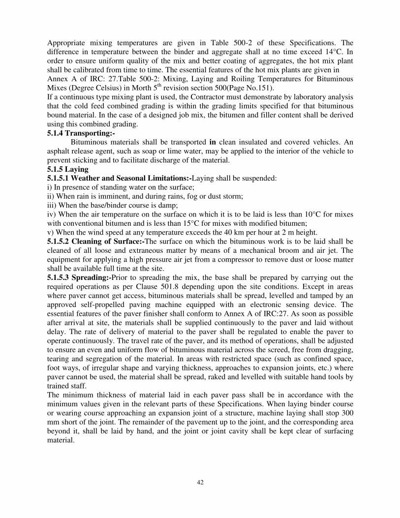
42
Appropriate mixing temperatures are given in Table 500-2 of these Specifications. The
difference in temperature between the binder and aggregate shall at no time exceed 14°C. In
order to ensure uniform quality of the mix and better coating of aggregates, the hot mix plant shall be calibrated from time to time. The essential features of the hot mix plants are given in
Annex A of IRC: 27.Table 500-2: Mixing, Laying and Roiling Temperatures for Bituminous Mixes (Degree Celsius) in Morth 5th revision section 500(Page No.151). If a continuous type mixing plant is used, the Contractor must demonstrate by laboratory analysis that the cold feed combined grading is within the grading limits specified for that bituminous bound material. In the case of a designed job mix, the bitumen and filler content shall be derived using this combined grading. 5.1.4 Transporting:-
Bituminous materials shall be transported in clean insulated and covered vehicles. An asphalt release agent, such as soap or lime water, may be applied to the interior of the vehicle to prevent sticking and to facilitate discharge of the material. 5.1.5 Laying
5.1.5.1 Weather and Seasonal Limitations:-Laying shall be suspended: i) In presence of standing water on the surface; ii) When rain is imminent, and during rains, fog or dust storm; iii) When the base/binder course is damp; iv) When the air temperature on the surface on which it is to be laid is less than 10°C for mixes with conventional bitumen and is less than 15°C for mixes with modified bitumen; v) When the wind speed at any temperature exceeds the 40 km per hour at 2 m height. 5.1.5.2 Cleaning of Surface:-The surface on which the bituminous work is to be laid shall be cleaned of all loose and extraneous matter by means of a mechanical broom and air jet. The equipment for applying a high pressure air jet from a compressor to remove dust or loose matter shall be available full time at the site. 5.1.5.3 Spreading:-Prior to spreading the mix, the base shall be prepared by carrying out the required operations as per Clause 501.8 depending upon the site conditions. Except in areas where paver cannot get access, bituminous materials shall be spread, levelled and tamped by an approved self-propelled paving machine equipped with an electronic sensing device. The essential features of the paver finisher shall conform to Annex A of IRC:27. As soon as possible after arrival at site, the materials shall be supplied continuously to the paver and laid without delay. The rate of delivery of material to the paver shall be regulated to enable the paver to operate continuously. The travel rate of the paver, and its method of operations, shall be adjusted
to ensure an even and uniform flow of bituminous material across the screed, free from dragging, tearing and segregation of the material. In areas with restricted space (such as confined space, foot ways, of irregular shape and varying thickness, approaches to expansion joints, etc.) where paver cannot be used, the material shall be spread, raked and levelled with suitable hand tools by trained staff. The minimum thickness of material laid in each paver pass shall be in accordance with the minimum values given in the relevant parts of these Specifications. When laying binder course or wearing course approaching an expansion joint of a structure, machine laying shall stop 300 mm short of the joint. The remainder of the pavement up to the joint, and the corresponding area beyond it, shall be laid by hand, and the joint or joint cavity shall be kept clear of surfacing material.

43
Bituminous material, with a temperature greater than 145°C, shall not be laid or deposited on bridge deck water-proofing systems, unless precautions against heat damage have been approved by the Engineer. 5.1.5.4 Cleanliness and Overlaying
Bituminous material shall be kept clean and uncontaminated. The only traffic permitted to run on bituminous material to be overlaid shall be that engaged in laying and compacting the next course or, where a binder course is to be sealed or surface dressed, that engaged on such surface treatment. Should any bituminous material become contaminated, the Contractor shall make it good to the satisfaction of the Engineer, in compliance with Clause 501.8. Binder course material shall be covered by either the wearing course or surface treatment, whichever is specified in the Contract. 5.1.6 Compaction:-Bituminous materials shall be laid and compacted in layers, which enable the specified thickness, surface level, regularity requirements and compaction to be achieved. Compaction of bituminous materials shall commence as soon as possible after laying. Compaction shall be substantially completed before the temperature falls below the minimum
rolling temperatures stated in the relevant part of these Specifications. Rolling of the longitudinal joints shall be done immediately behind the paving operation. After this, rolling shall commence at the edges and progress towards the center longitudinally except that on super-elevated and unidirectional cambered portions, it shall progress from the lower to the upper edge parallel to the center line of the pavement. Rolling shall continue until all roller marks have been removed from the surface. All deficiencies in the surface after laying shall be made good by the attendants behind the paver, before initial rolling is commenced. The initial or breakdown rolling shall be done with 8-10 tonne static weight smooth-wheel rollers. The intermediate rolling shall be done with 8-10 tonne static weight or vibratory roller or with a pneumatic tyred roller of 12 to 15 tonne weight, with a tyred pressure of at least 0.56 MPa. The Contractor shall demonstrate the efficiency of the equipment proposed to be used by carrying compaction trials. The procedure for site trials shall be submitted to the Engineer for approval. The finish rolling shall be done with 6 to 8 tonne smooth wheel tandem rollers. Rolling shall continue until the specified compaction is achieved. Where compaction is to be determined by density of cores, the requirements to prove the performance of rollers shall apply in order to demonstrate that the specified density can be achieved. In such cases the Contractor shall specify the plant, and the method by which he intends to achieve the specified level of compaction and finish at temperatures above the minimum specified rolling temperature. Laying trials shall then demonstrate the acceptability of the plant and method used. Bituminous materials shall be rolled in a longitudinal direction, with the driven rolls nearest the paver. The roller shall first compact material adjacent to joints and then work from the lower to the upper side of the layer, overlapping on successive passes by at least one-third of the width of the rear roll or, in the case of a pneumatic-tyred roller, at least the nominal width of 300 mm. In portions with super-elevated and unidirectional camber, after the edge has been rolled, the roller shall progress from the lower to the upper edge. Rollers should move at a speed of not more than 5 km per hour. The roller shall not be permitted to stand on pavement which has not been fully compacted, and necessary precautions shall be taken to prevent dropping of oil, grease, petrol! Diesel or other foreign matter on the pavement either when the rollers are operating or standing. The wheels of roller machine shall be in good working order, to prevent the mix from adhering to the wheels. Only sufficient moisture to prevent adhesion between the wheels of rollers and the mix should be used. Surplus water shall not be allowed to stand on the partially compacted pavement.

44
5.1.7 Joints 5.1.7.1 Where joints are made, the material shall be fully compacted and the joint made flush in one of the following ways: a) All joints shall be cut vertical to the full thickness of the previously laid mix. All loosened material shall be discarded and the vertical face coated with a suitable viscosity grade hot bitumen, or cold applied emulsified bitumen. While spreading the material along the joint the material spread shall overlap 25 mm to 50 mm on the previously laid mix beyond the vertical face of the joint. The thickness of the loose overlap material should be approximately a quarter more than the final compacted thickness. The overlapped mix shall be dragged back to the hot lane so that the roller can press the small excess into the hot side of the joint to obtain a high joint density. b) By using two or more pavers operating in echelon, where this is practicable and in sufficient proximity for adjacent widths to be fully compacted by continuous rolling. 5.1.7.2 All longitudinal joints shall be offset at least 300 mm from parallel joints in the layer beneath or as directed, and in a layout approved by the Engineer. Joints in the wearing course shall coincide with either the lane edge or the lane marking, whichever is appropriate. Longitudinal joints shall not be situated in wheel track zones. 5.1.7.3 For transverse joints method a) above shall apply. Transverse joints in the successive and adjoining layers shall have a minimum offset of 2 m. 5.1.8 Preparation of Surface
5.1.8.1 Scope:-This work shall consist of preparing an existing granular or black-topped surface for laying bituminous course. The work shall be performed on such widths and lengths as shown on the drawings or as instructed by the Engineer. The existing surface shall be firm and clean, and treated with Prime or Tack coat where specified in the Contract. 5.1.8.2 Materials
5.1.8.2.1 For Scarifying and Re-Laying the Granular Surface:-The material used shall be coarse aggregates salvaged from the scarification of the existing granular base course supplemented by fresh coarse aggregates and screenings so that aggregates and screenings thus
supplemented correspond to Clauses 404 or 406. 5.1.8.2.2 For Patching Potholes and Sealing Cracks:-Where the existing surface to be overlaid is bituminous, material required for patching and sealing cracks shall be in accordance with Clauses 3004.2 and 3004.3, or as directed by the Engineer. 5.1.8.2.3 for Profile Corrective Course:-The type of material for use as profile corrective course shall be as shown on the drawings or as directed by the Engineer. Where it is to be laid as part of the overlay! Strengthening course, the profile corrective course material shall be of the same specification as that of the overlay! Strengthening course. However, if provided as a separate layer, it shall be of the specification and details given in the Contract.
5.1.8.3 Construction Operations
5.1.8.3.1 Preparing Existing Granular Surface:-Where the existing surface is granular, all loose materials shall be removed, and the surface lightly watered where the profile corrective course to be provided as a separate layer is also granular. Where the profile corrective course of bituminous material is to be laid over the existing granular surface, the latter shall, after removal of all loose material, be primed in accordance with Clause 502 and a tack coat applied in accordance with Clause 503. The surface of all granular layers on which bituminous works are to be placed, shall be free from dust. All such layers must be capable of being swept, after the removal of any non-integral loose material, by means of a mechanical broom, without shedding
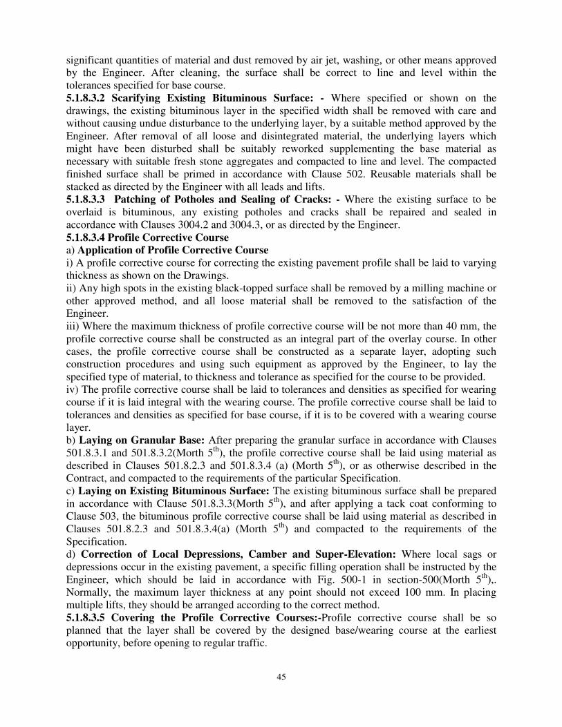
45
significant quantities of material and dust removed by air jet, washing, or other means approved by the Engineer. After cleaning, the surface shall be correct to line and level within the tolerances specified for base course. 5.1.8.3.2 Scarifying Existing Bituminous Surface: - Where specified or shown on the drawings, the existing bituminous layer in the specified width shall be removed with care and without causing undue disturbance to the underlying layer, by a suitable method approved by the Engineer. After removal of all loose and disintegrated material, the underlying layers which might have been disturbed shall be suitably reworked supplementing the base material as necessary with suitable fresh stone aggregates and compacted to line and level. The compacted finished surface shall be primed in accordance with Clause 502. Reusable materials shall be stacked as directed by the Engineer with all leads and lifts. 5.1.8.3.3 Patching of Potholes and Sealing of Cracks: - Where the existing surface to be overlaid is bituminous, any existing potholes and cracks shall be repaired and sealed in accordance with Clauses 3004.2 and 3004.3, or as directed by the Engineer. 5.1.8.3.4 Profile Corrective Course
a) Application of Profile Corrective Course
i) A profile corrective course for correcting the existing pavement profile shall be laid to varying thickness as shown on the Drawings. ii) Any high spots in the existing black-topped surface shall be removed by a milling machine or other approved method, and all loose material shall be removed to the satisfaction of the Engineer. iii) Where the maximum thickness of profile corrective course will be not more than 40 mm, the profile corrective course shall be constructed as an integral part of the overlay course. In other cases, the profile corrective course shall be constructed as a separate layer, adopting such construction procedures and using such equipment as approved by the Engineer, to lay the specified type of material, to thickness and tolerance as specified for the course to be provided. iv) The profile corrective course shall be laid to tolerances and densities as specified for wearing course if it is laid integral with the wearing course. The profile corrective course shall be laid to tolerances and densities as specified for base course, if it is to be covered with a wearing course layer. b) Laying on Granular Base: After preparing the granular surface in accordance with Clauses 501.8.3.1 and 501.8.3.2(Morth 5th), the profile corrective course shall be laid using material as described in Clauses 501.8.2.3 and 501.8.3.4 (a) (Morth 5th), or as otherwise described in the Contract, and compacted to the requirements of the particular Specification. c) Laying on Existing Bituminous Surface: The existing bituminous surface shall be prepared in accordance with Clause 501.8.3.3(Morth 5th), and after applying a tack coat conforming to Clause 503, the bituminous profile corrective course shall be laid using material as described in Clauses 501.8.2.3 and 501.8.3.4(a) (Morth 5th) and compacted to the requirements of the Specification. d) Correction of Local Depressions, Camber and Super-Elevation: Where local sags or depressions occur in the existing pavement, a specific filling operation shall be instructed by the Engineer, which should be laid in accordance with Fig. 500-1 in section-500(Morth 5th),. Normally, the maximum layer thickness at any point should not exceed 100 mm. In placing multiple lifts, they should be arranged according to the correct method. 5.1.8.3.5 Covering the Profile Corrective Courses:-Profile corrective course shall be so planned that the layer shall be covered by the designed base/wearing course at the earliest opportunity, before opening to regular traffic.
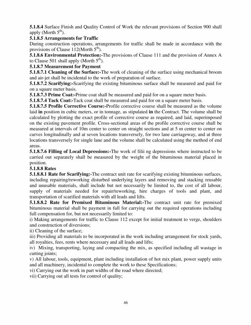
46
5.1.8.4 Surface Finish and Quality Control of Work the relevant provisions of Section 900 shall apply (Morth 5th). 5.1.8.5 Arrangements for Traffic
During construction operations, arrangements for traffic shall be made in accordance with the provisions of Clause 112(Morth 5th). 5.1.8.6 Environmental Protection:-The provisions of Clause 111 and the provision of Annex A to Clause 501 shall apply (Morth 5th). 5.1.8.7 Measurement for Payment
5.1.8.7.1 Cleaning of the Surface:-The work of cleaning of the surface using mechanical broom and air-jet shall be incidental to the work of preparation of surface. 5.1.8.7.2 Scarifying:-Scarifying the existing bituminous surface shall be measured and paid for on a square meter basis. 5.1.8.7.3 Prime Coat:-Prime coat shall be measured and paid for on a square meter basis. 5.1.8.7.4 Tack Coat:-Tack coat shall be measured and paid for on a square meter basis. 5.1.8.7.5 Profile Corrective Course:-Profile corrective course shall be measured as the volume laid in position in cubic meters, or in tonnage, as stipulated in the Contract. The volume shall be calculated by plotting the exact profile of corrective course as required, and laid, superimposed on the existing pavement profile. Cross-sectional areas of the profile corrective course shall be measured at intervals of 10m center to center on straight sections and at 5 m center to center on curves longitudinally and at seven locations transversely, for two lane carriageway, and at three
locations transversely for single lane and the volume shall be calculated using the method of end areas. 5.1.8.7.6 Filling of Local Depressions:-The work of filii ng depressions where instructed to be carried out separately shall be measured by the weight of the bituminous material placed in position. 5.1.8.8 Rates
5.1.8.8.1 Rate for Scarifying:-The contract unit rate for scarifying existing bituminous surfaces, including repairing/reworking disturbed underlying layers and removing and stacking reusable and unusable materials, shall include but not necessarily be limited to, the cost of all labour, supply of materials needed for repair/reworking, hire charges of tools and plant, and transportation of scarified materials with all leads and lifts. 5.1.8.8.2 Rate for Premixed Bituminous Material:-The contract unit rate for premixed bituminous material shall be payment in full for carrying out the required operations including full compensation for, but not necessarily limited to: i) Making arrangements for traffic to Clause 112 except for initial treatment to verge, shoulders and construction of diversions; ii) Cleaning of the surface; iii) Providing all materials to be incorporated in the work including arrangement for stock yards, all royalties, fees, rents where necessary and all leads and lifts; iv) Mixing, transporting, laying and compacting the mix, as specified including all wastage in cutting joints; v) All labour, tools, equipment, plant including installation of hot mix plant, power supply units and all machinery, incidental to complete the work to these Specifications; vi) Carrying out the work in part widths of the road where directed; vii) Carrying out all tests for control of quality;
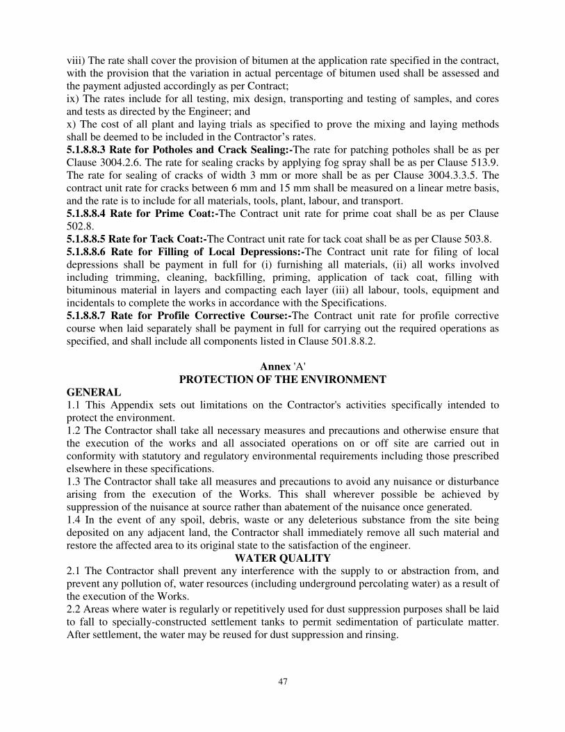
47
viii) The rate shall cover the provision of bitumen at the application rate specified in the contract, with the provision that the variation in actual percentage of bitumen used shall be assessed and the payment adjusted accordingly as per Contract; ix) The rates include for all testing, mix design, transporting and testing of samples, and cores and tests as directed by the Engineer; and x) The cost of all plant and laying trials as specified to prove the mixing and laying methods shall be deemed to be included in the Contractor’s rates. 5.1.8.8.3 Rate for Potholes and Crack Sealing:-The rate for patching potholes shall be as per Clause 3004.2.6. The rate for sealing cracks by applying fog spray shall be as per Clause 513.9. The rate for sealing of cracks of width 3 mm or more shall be as per Clause 3004.3.3.5. The contract unit rate for cracks between 6 mm and 15 mm shall be measured on a linear metre basis, and the rate is to include for all materials, tools, plant, labour, and transport. 5.1.8.8.4 Rate for Prime Coat:-The Contract unit rate for prime coat shall be as per Clause 502.8. 5.1.8.8.5 Rate for Tack Coat:-The Contract unit rate for tack coat shall be as per Clause 503.8. 5.1.8.8.6 Rate for Filling of Local Depressions:-The Contract unit rate for filing of local depressions shall be payment in full for (i) furnishing all materials, (ii) all works involved including trimming, cleaning, backfilling, priming, application of tack coat, filling with bituminous material in layers and compacting each layer (iii) all labour, tools, equipment and incidentals to complete the works in accordance with the Specifications. 5.1.8.8.7 Rate for Profile Corrective Course:-The Contract unit rate for profile corrective course when laid separately shall be payment in full for carrying out the required operations as specified, and shall include all components listed in Clause 501.8.8.2.
Annex 'A' PROTECTION OF THE ENVIRONMENT
GENERAL
1.1 This Appendix sets out limitations on the Contractor's activities specifically intended to protect the environment. 1.2 The Contractor shall take all necessary measures and precautions and otherwise ensure that the execution of the works and all associated operations on or off site are carried out in conformity with statutory and regulatory environmental requirements including those prescribed elsewhere in these specifications. 1.3 The Contractor shall take all measures and precautions to avoid any nuisance or disturbance arising from the execution of the Works. This shall wherever possible be achieved by suppression of the nuisance at source rather than abatement of the nuisance once generated. 1.4 In the event of any spoil, debris, waste or any deleterious substance from the site being deposited on any adjacent land, the Contractor shall immediately remove all such material and restore the affected area to its original state to the satisfaction of the engineer.
WATER QUALITY
2.1 The Contractor shall prevent any interference with the supply to or abstraction from, and prevent any pollution of, water resources (including underground percolating water) as a result of the execution of the Works. 2.2 Areas where water is regularly or repetitively used for dust suppression purposes shall be laid to fall to specially-constructed settlement tanks to permit sedimentation of particulate matter. After settlement, the water may be reused for dust suppression and rinsing.

48
2.3 All water and other liquid waste products arising on the site shall be collected and disposed of at a location on or off the site and in a manner that shall not cause nuisance or pollution. 2.4 The Contractor shall not discharge or deposit any matter arising from the execution of the Works into any waters except with the permission of the Engineer and the regulatory authorities concerned. 2.5 The Contractor shall at all times ensure that all existing stream courses and drains within, and adjacent to, the site are kept safe and free from any debris and any materials arising from the Works. 2.6 The Contractor shall protect all watercourses, waterways, ditches, canals, drains, lakes and the like from pollution as a result of the execution of the Works.
AIR QUALITY
3.1 The Contractor shall devise and arrange methods of working to minimize dust, gaseous or other air-borne emissions and carry out the Works in such a manner as to minimize adverse impacts on air quality. 3.2 The Contractor shall utilize effective water sprays during delivery, manufacture, processing and handling of materials when dust is likely to be created, and to dampen stored materials during dry and windy weather. Stockpiles of friable materials shall be covered with clean tarpaulins, with application of sprayed water during dry and windy weather. Stockpiles of material or debris shall be dampened prior to their movement, except where this is contrary to the Specifications. 3.3 Any vehicle with an open load-carrying area used for transporting potentially dust producing material shall have properly fitting side and tail boards. Materials having the potential to produce dust shall not be loaded to a level higher than the side and tail boards, and shall be covered with a clean tarpaulin in good condition. The tarpaulin shall be properly secured and extended at least 300 mm over the edges of the side and tail boards. 3.4 In the event that the Contractor is permitted to use gravel or earth roads for haulage, he shall provide suitable measures for dust palliation, if these are, in the opinion of the Engineer, necessary. Such measures may include sprinkling water on the road surface at regular intervals.
NOISE
4.1 The Contractor shall consider noise abutment measures in his planning and execution of the Works. 4.2 The Contractor shall take all necessary measures so that the operation of all mechanical equipment and construction processes on and off the site shall not cause any unnecessary or excessive noise, taking into account applicable environmental requirements. The Contractor shall use all necessary measures and shall maintain all plant and silencing equipment in good condition so as to minimize the noise emission during construction works.
CONTROL OF WASTES
5.1 The Contractor shall control the disposal of all forms of waste generated by the construction operations and in all associated activities. No uncontrolled deposition or dumping shall be permitted. Wastes to be so controlled shall include, but shall not be limited to, all forms of fuel and engine oils, all types of bitumen, cement, surplus aggregates, gravels, bituminous mixes etc. The Contractor shall make specific provision for the proper disposal of these and any other waste products, conforming to local regulations and acceptable to the Engineer.
EMERGENCY RESPONSE
6.1 The Contractor shall plan and provide for remedial measures to be implemented in the event of occurrence of emergencies such as spillages of oil or bitumen or chemicals.
49
6.2 The Contractor shall provide the Engineer with a .statement of the measures he intends to implement in the event of such an emergency, which shall include a statement of how he intends to provide personnel adequately trained to implement such measures.
MEASUREMENT
7.1 No separate measurement shall be made in respect of compliance by the Contractor with these provisions. The Contractor shall be deemed to have made allowance for such compliance with these provisions in the preparation of his prices for items of work included in the Bill of Quantities and full compensation for such compliance will be deemed to be covered by them. 5.2 PRIME COAT OVER GRANULAR BASE
5.2.1 Scope:-This work shall consist of the application of a single coat of low viscosity liquid bituminous material to a porous granular surface preparatory to the superimposition of bituminous treatment or mix. The work shall be carried out on a previously prepared granular/ stabilized surface to Clause 501.8. 5.2.2 Materials
5.2.2.1 The primer shall be cationic bitumen emulsion SS1 grade conforming to IS:8887 or medium curing cutback bitumen conforming to IS:217 or as specified in the Contract. 5.2.2.2 Quantity of SS 1 grade bitumen emulsion for various types of granular surface shall be as given in Table 500-3 in Morth 5th revision Section-500 (Page No.166). 5.2.2.3 Cutback for primer shall not be prepared at the site. Type and quantity of cutback bitumen for various types of granular surface shall be as given in Table 500-4 in in Morth 5th revision Section-500 (Page No.166). 5.2.2.4 The correct quantity of primer shall be decided by the Engineer and shall be such that it can be absorbed by the surface without causing run-off of excessive primer and to achieve desired penetration of about 8-10 mm. 5.2.3 Weather and Seasonal Limitations:-Primer shall not be applied during a dust storm or when the weather is foggy, rainy or windy or when the temperature in the shade is less than 1 OOC. Cutback bitumen as primer shall not be applied to a wet surface. Surfaces which are to receive emulsion primer should be damp, but no free or standing water shall be present. Surface can be just wet by very light sprinkling of water. 5.2.4 Construction
5.2.4.1 Equipment:-The primer shall be applied by a self-propelled or towed bitumen pressure sprayer equipped for spraying the material uniformly at specified rates and temperatures. Hand spraying shall not be allowed except in small areas, inaccessible to the distributor, or in narrow strips where primer shall be sprayed with a pressure hand sprayer, or as directed by the Engineer. 5.2.4.2 Preparation of Road Surface:-The granular surface to be primed shall be swept clean by power brooms or mechanical sweepers and made free from dust. All loose material and other foreign material shall be removed completely. If soil/ moorum binder has been used in the WBM surface, part of this should be brushed and removed to a depth of about 2 mm so as to achieve good penetration. 5.2.4.3 Application of Bituminous Primer:- After preparation of the road surface as per Clause 502.4.2, the primer shall be sprayed uniformly at the specified rate. The method for application of the primer will depend on the type of equipment to be used, size of nozzles, pressure at the spray bar and speed of forward movement. The Contractor shall demonstrate at a spraying trial, that the equipment and method to be used is capable of producing a uniform spray, within the tolerances specified. No heating or dilution of SS1 bitumen emulsion and shall be permitted at site. Temperature of cutback bitumen shall be high enough to permit the primer to be sprayed effectively though the jets of the spray and to cover the surface uniformly.
50
5.2.4.4 Curing of Primer and Opening to Traffic:- A primed surface shall be allowed to cure for at least 24 hours or such other higher period as is found to be necessary to allow all the moisture/volatiles to evaporate before any subsequent surface treatment or mix is laid. Any unabsorbed primer shall first be blotted with a light application of sand, using the minimum quantity possible. A primed surface shall not be opened to traffic other than that necessary to lay the next course. 5.2.5 Quality Control of Work:-For control of the quality of materials and the works carried out, the relevant provisions of Section 900 shall apply. 502.6 Arrangements for Traffic During construction operations, arrangements for traffic shall be made in accordance with the provisions of Clause 112. 5.2.7 Measurement for Payment: - Prime coat shall be measured in terms of surface area of application in square metres. 5.2.8 Rate:-The contract unit rate for prime coat shall be payment in full for carrying out the required operations including full compensation for all components listed in Clause 401.7 (i) to (v) and as applicable to the work specified in these Specifications. Payment shall be made on the basis of the provision of prime coat at an application rate of quantity at 0.6 kg per square metre or at the rate specified in the Contract, with adjustment, plus or minus, for the variation between this quantity and the actual quantity approved by the Engineer after the preliminary trials referred to in Clause 502.4.3. 5.3 TACK COAT
5.3.1 Scope:-The work shall consist of the application of a single coat of low viscosity liquid bituminous material to existing bituminous, cement concrete or primed granular surface preparatory to the superimposition of a bituminous mix, when specified in the Contract or as instructed by the Engineer. The work shall be carried out on a previously prepared surface in accordance with Clause 501.8. 5.3.2 Materials:- The binder used for tack coat shall be either Cationic bitumen emulsion (RS 1) complying with IS:8887 or suitable low viscosity paving bitumen of VG 10 grade conforming to IS:73. The use of cutback bitumen RC:70 as per IS:217 shall be restricted only for sites at sub-zero temperatures or for emergency applications as directed by the Engineer. The type and grade
of binder for tack coat shall be as specified in the Contract or as directed by the Engineer. 5.3.3 Weather and Seasonal Limitations: - Bituminous material shall not be applied during a dust storm or when the weather is foggy, rainy or windy or when the temperature in the shade is less than 10°C. Where the tack coat. Consists of emulsion, the surface shall be slightly damp, but not wet. Where the tack coat is of cutback bitumen, the surface shall be dry. 5.3.4 Construction
5.3.4.1 Equipment
The tack coat shall be applied by a self-propelled or towed bitumen pressure sprayer, equipped for spraying the material uniformly at a specified rate. Hand spraying shall not be permitted except in small areas, inaccessible to the distributor, or narrow strips, shall be sprayed with a pressure hand sprayer, or as directed by the Engineer. 5.3.4.2 Preparation of Base:-The surface on which the tack coat is to be applied shall be clean and free from dust, dirt, and any extraneous material, and be otherwise prepared in accordance with the requirements of Clauses 501.B. The granular or stabilized surfaces shall be primed as per Clause 502. Immediately before the application of the tack coat, the surface shall be swept clean with a mechanical broom, and high pressure air jet, or by other means as directed by the
Engineer.

51
5.3.4.3 Application of Tack Coat:-The application of tack coat shall be at the rate specified in Table 500-5, and it shall be applied uniformly. If rate of application of Tack Coat is not specified in the contract, then it shall be the rate specified in Table 500-5. No dilution or heating at site of RS1 bitumen emulsion shall be permitted. Paving bitumen if used for tack coat shall be heated to appropriate temperature in bitumen boilers to achieve viscosity less than 2 poise. The normal range of spraying temperature for a bituminous emulsion shall be 20°C to 70°C and for cutback, 50°C to 80°C. The method of application of tack coat will depend on the type of equipment to be used, size of nozzles, pressure at the spray bar, and speed or forward movement. The Contractor shall demonstrate at a spraying trial, that the equipment and method to be used is capable of producing a uniform spray, within the tolerances specified. Table 500-5: Rate of Application of Tack Coat in Morth 5th revision Section-500 (Page No.169). 5.3.4.4 Curing of Tack Coat: - The tack coat shall be left to cure until all the volatiles have evaporated before any subsequent construction is started. No plant or vehicles shall be allowed on the tack coat other than those essential for the construction. 5.3.5 Quality Control of Work: - For control of the quality of materials and the works carried out, the relevant provisions of Section 900 shall apply. 5.3.6 Arrangements for Traffic:-During the period of construction, arrangements for traffic shall be made in accordance with the provisions of Clause 112. 5.3.7 Measurement for Payment:-Tack coat shall be measured in terms of surface area of application in square meters. 5.3.8 Rate:-The contract unit rate for tack coat shall be payment in full for carrying out the required operations including for all components listed in Clause 401.8 (i) to (v) and as applicable to the work specified in these Specifications. The rate shall cover the provision of tack coat, at 0.2 kg per square meter or at the rate specified in the Contract, with the provision that the variation between this quantity and actual quantity of bitumen used will be assessed and the payment adjusted accordingly. 5.4 DENSE BITUMINOUS MACADAM
5.4.1 Scope:-The specification describes the design and construction procedure for Dense Bituminous Macadam, (DBM), for use mainly, but not exclusively, in base/binder and profile corrective courses. The work shall consist of construction in a single or multiple layers of DBM on a previously prepared base or sub-base. The thickness of a single layer shall be 50 mm to 100 mm. 5.4.2 Materials
5.4.2.1 –Bitumen:-The bitumen shall be viscosity grade paving bitumen complying with the Indian Standard Specification IS:73, modified bitumen complying with Clause 501.2.1 or as otherwise specified in the Contract. The type and grade of bitumen to be used shall be specified in the Contract.
5.4.2.2 Course Aggregates:-The coarse aggregates shall consist of crushed rock, crushed gravel or other hard material retained on 2.36 mm sieve. They shall be clean, hard, and durable, of cubical shape, free from dust and soft or friable matter, organic or other deleterious substances. Where the Contractor's selected source of aggregates has poor affinity for bitumen, the Contractor shall produce test results that with the use of anti-stripping agents, the stripping value is improved to satisfy the specification requirements. The Engineer may approve such a source and as a condition for the approval of that source, the bitumen shall be treated with an approved anti-stripping agent, as per the manufacturer's recommendations, at the cost of the Contractor.
52
The aggregates shall satisfy the requirements specified in Table 500-8. Where crushed gravel is proposed for use as aggregate, not less than 90 percent by weight of the crushed material retained on the 4.75 mm sieve shall have at least two fractured faces. 5.4.2.3 Fine Aggregates:-Fine aggregates shall consist of crushed or naturally occurring mineral material, or a combination of the two, passing the 2.36 mm sieve and retained on the 75 micron sieve. These shall be clean, hard, durable, dry and free from dust, and soft or friable matter, organic or other deleterious matter. Natural sand shall not be allowed in binder courses. However, natural sand up to 50 percent of the fine aggregate may be allowed in base courses. The fine aggregate shall have a sand equivalent value of not less than 50 when tested in accordance with the requirement of IS: 2720 (Part 37). The plasticity index of the fraction passing the 0.425 mm sieve shall not exceed 4, when tested in accordance with IS: 2720 (Part 5). 5.4.2.4 Filler:-Filter shall consist of finely divided mineral matter such as rock dust, hydrated lime or cement approved by the Engineer. The filler shall be graded within the limits indicated in
Table 500-9. The filler shall be free from organic impurities and have a plasticity Index not greater than 4. The Plasticity Index requirement shall not apply if filler is cement or lime. Where the aggregates fail to meet the requirements of the water sensitivity test in Table 500-8, then 2 percent by total weight of aggregate, of hydrated lime shall be used and percentage of fine aggregate reduced accordingly. 5.4.2.5 Aggregate Grading and Binder Content
5.4.2.5.1 When tested in accordance with IS: 2386 Part 1 (wet sieving method), the combined grading of the coarse and fine aggregates and filler for the particular mixture shall fall within the limits given in Table 500-10 for grading 1 or 2 as specified in the Contract. To avoid gap grading, the combined aggregate gradation shall not vary from the lower limit on one sieve to higher limit on the adjacent sieve. Table 500-8 : Physical Requirements for Coarse Aggregate for Dense Bituminous Macadam in Morth 5th revision in section-500 (Page No.176). 5.4.3 Construction Operations
5.4.3.1 Weather and Seasonal Limitations:-The provisions of Clause 501.5.1 shall apply. 5.4.3.2 Preparation of Base:-The base on which Dense Graded Bituminous Material is to be laid shall be prepared in accordance with Clauses 501 and 902 as appropriate, or as directed by the Engineer. 5.4.3.3 Geosynthetics:-Where Geosynthetics are specified in the Contract, this shall be in accordance with the requirements stated in Clause 703. 5.4.3.4 Stress Absorbing Layer:-Where a stress absorbing layer is specified in the Contract, this shall be applied in accordance with the requirements of Clause 517. 5.4.3.5 Prime Coat:-Where the material on which the dense bituminous macadam is to be laid is other than a bitumen bound layer, a prime coat shall be applied, as specified, in accordance with the provisions of Clause 502, or as directed by the Engineer.
5.4.3.6 Tack Coat:- Where the material on which the dense bituminous macadam is to be laid is either bitumen bound layer or primed granular layer, tack coat shall be applied, as specified, in accordance with the provisions of Clause 503, or as directed by the Engineer. 5.4.3.7 Mixing and Transportation of the Mix:- The provisions as specified in Clauses 501.3 and 501.4 shall apply. Table 500-2 gives the mixing, laying and rolling temperature for dense mixes using viscosity grade bitumen. In case of modified bitumen, the temperature of mixing and compaction shall be higher than the mix with viscosity grade bitumen. The exact temperature depends upon the type and amount of modifier used and shall be adopted as per the
53
recommendations of the manufacturer. In order to have uniform quality, the plant shall be calibrated from time to time. 5.4.3.8 Spreading:-The provisions of Clauses 501.5.3 and 501.5.4(Morth 5th revision)shall apply. 5.4.3.9 Rolling:-The general provisions of Clauses 501.6 and 501.7 shall apply, as modified by the approved laying trials. The compaction process shall be carried out by the same plant, and using the same method, as approved in the laying trials, which may be varied only with the express approval of the Engineer in writing. 5.4.4 Opening to Traffic:- It shall be ensured that the traffic is not allowed without the approval of the Engineer in writing, on the surface until the dense bituminous layer has cooled to the ambient temperature. 5.4.5 Surface Finish and Quality Control of Work:-The surface finish of the completed construction shall conform to the requirements of Clause 902. All materials and workmanship shall comply with the provisions set out in Section 900 of these Specifications. 5.4.6 Arrangements for Traffic:-During the period of construction, arrangements for traffic shall be made in accordance with the provisions of Clause 112. 5.4.7 Measurement for Payment:-Dense Graded Bituminous Materials shall be measured as finished work either in cubic meters, tonnes or by the square meter at a specified thickness as indicated in the Contract drawings, or documents, or as otherwise directed by the Engineer. 5.4.8 Rate:-The contract unit rate for Dense Graded Bituminous Macadam shall be payment in full for carrying out all the required operations as specified and shall include, to all components
listed in Clause 501.8.8.2. The rate shall include the provision of bitumen, at 4 percent and 4.5 percent by weight of the total mixture for grading 1 and grading 2 respectively. The variation in actual percentage of bitumen used shall be assessed and the payment adjusted plus or minus accordingly. 5.5 BITUMINOUS CONCRETE
5.5.1 Scope:-This work shall consist of construction of Bituminous Concrete, for use in wearing and profile corrective courses. This work shall consist of construction in a single layer of bituminous concrete on a previously prepared bituminous bound surface. A single layer shall be
30 mm/40 mm/50 mm thick. 5.5.2 Materials
5.5.2.1 Bitumen:-The bitumen shall conform to Clause 504.2.1. 5.5.2.2 Course Aggregates:-The coarse aggregates shall be generally as specified in Clause 504.2.2, except that the aggregates shall satisfy the physical requirements of Table 500-16 and where crushed gravel is proposed for use as aggregate, not less than 95 percent by weight of the crushed material retained on the 4.75 mm sieve shall have at least two fractured faces. Table 500-16: Physical Requirements for Coarse Aggregate for Bituminous Concrete in Morth 5th revision in Section 500 (Page No.188).
5.5.2.3 Fine Aggregates:-The fine aggregates shall be all as specified in Clause 505.2.3 (Morth 5th revision). 5.5.2.4 Filler:-Filler shall be as specified in Clause 505.2.4. 5.6.2.5 Aggregate Grading and Binder Content: - When tested in accordance with IS: 2386 Part 1 (Wet grading method), the combined grading of the coarse and fine aggregates and filler shall fall within the limits shown in Table 500-17. The grading shall be as specified in the Contract. Table 500-17: Composition of Bituminous Concrete Pavement Layers in Morth 5th revision in Section 500 (Page No.189).
54
5.6.3 Construction Operations 5.6.3.1 Weather and Seasonal Limitations:-The provisions of Clause 501.5.1 shall apply. 5.6.3.2 Preparation of Base:-The surface on which the bituminous concrete is to be laid shall be prepared in accordance with Clauses 501 and 902 as appropriate, or as directed by the Engineer. The surface shall be thoroughly swept clean by mechanical broom and dust removed by compressed air. In locations where a mechanical broom cannot get access, other approved methods shall be used as directed by the Engineer. 5.6.3.3 Geosynthetics:-Where Geosynthetics are specified in the Contract, this shall be in accordance with the requirements stated in Clause 703. 5.6.3.4 Stress Absorbing Layer:-Where a stress absorbing layer is specified in the Contract, this shall be applied in accordance with the requirements of Clause 517. 5.6.3.4 Tack Coat:-The provisions as specified in Clause 504.4.6 shall apply. 5.6.3.5 Mixing and Transportation of the Mix:-The provisions as specified in Clauses 501.3, 501.4 and 504.4.7(Morth 5th) shall apply. 5.6.3.6 Spreading:-The general provisions of Clauses 501.6 and 501.7 shall apply, as modified by the approved laying trials. 5.6.3.7 Rolling:-The general provisions of Clauses 501.6 and 501.7 shall apply, as modified by the approved laying trials. 5.6.3.8 Opening to Traffic:-Provisions in Clause 504.5 shall apply. 5.6.3.9 Surface Finish and Quality Control:-The surface finish of the completed construction shall conform to the requirements of Clause 902. All materials and workmanship shall comply with the provisions set out in Section 900 of these Specifications. 5.6.4 Arrangements for Traffic:-During the period of construction, arrangements for traffic shall be made in accordance with the provisions of Clause 112. 5.6.5 Measurement for Payment The measurement shall be as specified in Clause 505.S. 5.6.6 Rate: - The contract unit rate shall be all as specified in Clause 504.9, except that the rate shall include the provision of bitumen at 5.2 percent & 5.4 percent for grading 1 and grading 2 by weight of total mix respectively. The variation in actual percentage of bitumen used will be assessed and the payment adjusted plus and minus accordingly.
6. TRAFFIC SIGNS AND ROAD MARKING (Morth 5th Revision Section-800)
6.1 Scope:-The work shall consist of the fabrication, supply and installation of ground mounted traffic signs on roads. The details of the signs shall be as shown in the drawings and in conformity with the Code of Practice for Road Signs, IRC: 67-2010. 6.2 Materials The various materials and fabrication of the traffic signs shall conform to the following requirements: 6.2.1 Concrete:-Concrete for foundation shall be of M 15 Grade as per Section 1700 or the grade shown on the drawings or otherwise as directed by the Engineer. 6.2.2 Reinforcing Steel:-Reinforcing steel shall conform to the requirement of IS: 1786 unless otherwise shown on the drawing. 6.2.3 Bolts, Nuts, Washers:-High strength bolts shall conform to IS: 1367 whereas precision bolts, nuts, etc., shall conform to IS: 1364. 6.2.4 Plates and Supports:-Plates and support sections for the sign posts shall conform to IS: 226 and IS: 2062 or any other relevant IS Specifications. 6.2.5 Substrate:-Sign panels shall be fabricated on aluminium sheet, aluminium composite panel, fiber glass sheeting, or sheet moulding compound. Aluminum sheets used for sign boards
55
shall be of smooth, hard and corrosion resistant aluminium alloy conforming to IS: 736-Material Designation 24345 or 1900.Aluminium Composite Material (ACM) sheets shall be sandwiched
construction with a thermoplastic core of Low Density Polyethylene (LOPE) between two thick skins/sheets of aluminium with overall thickness and 3 mm or 4 mm (as specified in the
Contract), and aluminium skin of thickness 0.5 mm and 0.3 mm respectively on both sides. The mechanical proportion of ACM and that of aluminium skin shall conform to the requirements given in Table 800-1(Morth 5th), when tested in accordance with the test methods mentioned against each of them. 6.2.6 Plate Thickness:-Shoulder mounted ground sings with a maximum side dimension not exceeding 600 mm shall not be less than 1.5 mm thick with Aluminium and 3 mm thick with Aluminium Composite Material. All other signs be at least 2 mm thick with Aluminium and 4 mm thick with Aluminium Composite Material. The thickness of the sheet shall be related to the size of the sign and its support and shall be such that it does not bend or deform under prevailing wind and other loads. 6.2.7 In respect of sign sizes not covered by IRC: 67, the structural details (thickness, etc.) shall be as per the approved drawings or as directed by the Engineer. 6.3 Traffic Signs having Retro-Reflective Sheeting
6.3.1 General Requirements:-The retro-reflective sheeting used on the sign shall consist of the white or colored sheeting having a smooth outer surface which has the property of retro-reflection over its entire surface it shall be weather-resistant and show color fastness. It shall be new and unused and shall show no evidence of cracking, scaling, and pitting, blistering, edge lifting or curling and shall have negligible shrinkage or expansion. A certificate of having tested the sheeting for co-efficient of retro-reflection, day/night time color luminous, shrinkage, flexibility, linear removal, adhesion, impact resistance, specular gloss and fungus resistance and its having- passed these tests shall be obtained from a Government Laboratory/institute, by the manufacturer of the sheeting. The retro-reflective sheeting shall be either of Engineering Grade material with enclosed lens, High Intensity Grade with encapsulated lens or Micro-prismatic Grade retro-reflective element material as given in Clauses 801.3.2 to 801.3.7. Guidance on the recommended application of each class of sheeting may be taken from IRC: 67. 6.3.7 Messages/Borders The messages (legends, letters, numerals etc.) and borders shall either be screen-printed or of cut out from durable transparent overlay or cut out from the same type of reflective sheeting for the cautionary/mandatory sign boards. Screen printing shall be processed and finished with materials and in a manner specified by the sheeting manufacturer. For the informatory and other sign boards, the messages (legends, letters, numerals etc.) and borders shall be cut out from durable transparent overlay film or cut-out from the same reflective sheeting only. Cut-outs shall be from durable transparent overlay materials as specified by the sheeting manufacturer and shall be bonded with the sheeting in the manner specified by the manufacturer. For screen-printed transparent colored areas on white sheeting, the coefficient of retro-reflection shall not be less than 50 percent of the values of corresponding color in Tables 800-2 to 800-8 as applicable. Cut-out messages and borders, wherever used, shall be either made out of retro-reflective sheeting or made out of durable transparent overlay except those in black which shall be of non-reflective sheeting or opaque in case of durable transparent overlay. 6.3.8 Color for Signs
6.3.8.1 Signs shall be provided with retro-reflective sheeting and/or overlay film/ screening ink. The reverse side of all signs shall be painted grey.

56
6.3.8.2 Except in the case of railway level crossing signs the sing posts shall be painted in 250 mm side bands, alternately black and white. The lowest band next to be ground shall be in black. 6.3.8.3 The color of the material shall be located within the area defined by the chromaticity coordinates in Table 800-7 and comply with the luminance factor when measured as per ASTM 0-4956(Morth 5th). The colors shall be durable and uniform in acceptable hue when viewed in day light or under normal headlights at night. 6.3.8.4 The Regulatory/Prohibitory and warning signs shall be provided with white background and red border. The legend/ symbol for these signs shall be in black color. The Mandatory sign shall be provided with Blue background and white Symbol/letter. 6.3.8.5 The colors chosen for informatory or guide signs shall be distinct for different classes of roads. For National Highways and State Highways, these signs shall be of green background and for Expressways these signs shall be of blue background with white border, legends and word messages. 6.3.10 Sizes of Letters
6.3.10.1 Letter size should be chosen with due regard to the speed, classification and location of the road, so that the sign is of adequate size for legibility but without being too large or obtrusive. The size of the letter, in terms of x-height, to be chosen as per the design speed is given in Table 800-8(Morth 5th). The thickness of the letters and their relation to the x-height, the width, and the heights are indicated in Table IV (a) of the Annexure-4 of IRC: 67 to facilitate the design of the informatory signs and definition plates. 6.3.10.2 For advance direction signs on non-urban roads, the letter size ('x' height) should be minimum of 150 mm for Expressway, National and State Highways and 100 mm for other roads. In case of overhead signs, the size ('X' height) of letters may be minimum 300 mm. Thickness of the letter could be varied from 1/6 to 1/5 of the letter 'x' size. The size of the initial uppercase letter shall be 1-1/3 times x-height. In urban areas, letter size shall be 100 mm on all directional signs. For easy and better comprehension, the word messages shall be written in upper case letters only. 6.3.10.3 Letter size on definition plates attached with normal sized signs should be 100 mm or 150 mm. In the case of small signs, it should be 100 mm. Where the message is long, as for instance in "NO PARKING" and "NO STOPPING" signs, the message may be broken into two lines and size of letters may be varied in the lines so that the definition plate is not too large. The lettering on definition plates will be all in upper case letters. 6.3.11 Warranty and Durability:-The Contractor shall obtain from the manufacturer a ten year warranty for satisfactory field performance including stipulated retro-reflectance of the retro-reflective sheeting of micro-prismatic sheeting and a seven-year warranty for high intensity grade and submit the same to the Engineer. The warranty shall be inclusive of the screen printed or cut out letters/legends and their bonding to the retro-reflective sheeting. The Contractor supplier shall also furnish the LOT numbers and certification that the signs and materials supplied against the assigned work meets all the stipulated requirements and carry the stipulated warranty and that the
Contractor supplier is the authorized converter of the particular sheeting. All signs shall be dated during fabrication with indelible markings to indicate the start of warranty. The warranty shall also cover the replacement obligation by the sheeting manufacturer as well as contractor for replacement repair/restoration of the retro-reflective efficiency. A certificate in original shall be given by the sheeting manufacturer that its offered retroreflective sheeting has been tested for various parameters such as co-efficient of retro reflection, day/night

57
time color and luminance, shrinkage, flexibility, linear removal, adhesion, impact resistance, specular gloss and fungus resistance; the tests shall be carried out by a Government Laboratory in accordance with various ASTM procedures and the results must show that the sheeting has passed the requirements for all the above mentioned parameters. A copy of the test reports shall be attached with the certificate. 6.4 Installation
6.4.1 The traffic signs shall be mounted on support posts, which may be of GI pipes conforming to IS:1239, Rectangular Hollow Section conforming to IS:4923 or Square Hollow Section conforming to IS:3589. Sign posts, their foundations and sign mountings shall be so constructed as to hold these in a proper and permanent position against the normal storm wind loads or displacement by vandalism. Normally, signs with an area up to 0.9 sq.m shall be mounted on a single post, and for greater area two or more supports shall be provided. Post-end(s) shall be firmly fixed to the ground by means of properly designed foundation. The work of foundation shall conform to relevant Specifications as specified. 6.4.2 All components of signs (including its back side) and supports, other than the reflective portion and G.I. posts shall be thoroughly de-scaled, cleaned, primed and painted with two coats of epoxy / fiber glass powder coated paint. Any part of support post below ground shall be painted with protective paint. 6.4.3 The signs shall be fixed to the posts by welding in the case of steel posts and by bolts and washers of suitable size. After the nuts have been tightened, the tails of the bolts shall be furred over with a hammer to prevent removal. 6.5 Measurement for Payment:-The measurement of standard cautionary, mandatory and information signs shall be in numbers of different types of signs supplied and fixed, while for direction and place identification signs, these shall be measured by area in square meters. 6.6 Rate:-The Contract unit rate shall be payment in full for the cost of making the road sign, including all materials, installing it at the site furnishing of necessary test certificates, warranty and incidentals to complete the work in accordance with these Specifications. 6.7 ROAD MARKINGS
6.7.1 Scope:-The work shall consist of providing road markings of specified width, layout and design using paint of the required specifications as given in the Contract and as per guidelines contained in from IRC:35-1997. 6.7.2 Materials:-Road markings shall be of ordinary road marking paint hot applied thermoplastic compound, reflectorized paint or cold applied reflective paint as specified in the item and the material shall meet the requirements as specified in these Specifications. 6.7.3 Ordinary Road Marking Paint 6.7.3.1 Ordinary paint used for road marking shall conform to Grade I as per IS:164. 6.7.3.2 The road marking shall preferably be laid with appropriate road marking machinery. 6.7.4 Hot Applied Thermoplastic Road Marking 6.7.4.1 Thermoplastic Material 6.7.4.1.1 General:-The thermoplastic material shall be homogeneously composed of aggregate, pigment, resins and glass reflectorizing beads. The color of the compound shall be white or yellow (IS color No. 356) as specified in the drawings or as directed by the Engineer.
58
6.7.4.1.2 Requirements: i) Composition: The pigment, beads, and aggregate shall be uniformly dispersed in the resin. The material shall be free from all skins, dirt and foreign objects and shall comply with requirements indicated in Table 800-9 (Morth 5th revision). ii) Properties: The properties of thermoplastic material, when tested in accordance with ASTM D36/BS-3262-(Part I), shall be as below: a) Luminance: White: Daylight luminance at 45°-65 percent min. as per AASHTO M 249 Yellow: Daylight luminance at 45°-45 percent min. as per AASHTO M249 b) Drying time: When applied at a temperature specified by the manufacturer and to the required thickness, the material shall set to bear traffic in not more than 15 minutes. c) Skid resistance: not less than 45 as per BS: 6044. d) Cracking resistance at low temperature: The material shall show no cracks on application to concrete blocks. e) Softening point: 102.5°C ± 9.5°C as per ASTM D 36. f) Yellowness index (for white thermoplastic paint): not more than 0.12 as per AASHTO M 249 iii) Storage life: The material shall meet the requirements of these Specifications for a period of one year. The thermoplastic material must also melt uniformly with no evidence of skins or un-melted particles for the one year storage period. Any material not meeting the above requirements shall be replaced by the manufacturer/supplier/ Contractor. iv) Reflectorisation: Shall be achieved by incorporation of beads, the grading and other properties of the beads shall be as specified in Clause 803.4.2. v) Marking: Each container of the thermoplastic material shall be clearly ~ and indelibly marked with the following information:, 1) The name, trade mark or other means of identification of manufacturer 2) Batch number 3) Date of manufacture 4) Color (white or yellow) 5) Maximum application temperature and maximum safe heating temperature. vi) Sampling and Testing: The thermoplastic material shall be sampled and tested in accordance with the appropriate ASTM/BS method. The Contractor shall furnish to the Engineer a copy of certified test reports from the manufacturers of the thermoplastic material showing results of all tests specified herein and shall certify that the material meets all requirements of this Specification. 6.8 ROAD MARKINGS
6.8.1 Scope:-The work shall consist of providing road markings of specified width, layout and design using paint of the required specifications as given in the Contract and as per guidelines contained in from IRC: 35-1997. 6.8.2 Materials:-Road markings shall be of ordinary road marking paint hot applied thermoplastic compound, reflectorized paint or cold applied reflective paint as specified in the item and the material shall meet the requirements as specified in these Specifications. 6.8.3 Ordinary Road Marking Paint 6.8.3.1 Ordinary paint used for road marking shall conform to Grade I as per IS: 164. 6.8.3.2 The road marking shall preferably be laid with appropriate road marking machinery. 6.8.4 Hot Applied Thermoplastic Road Marking
6.8.4.1 Thermoplastic Material
59
6.8.4.1.1 General:-The thermoplastic material shall be homogeneously composed of aggregate, pigment, resins and glass reflectorizing beads. The color of the compound shall be white or yellow (IS color No. 356) as specified in the drawings or as directed by the Engineer 6.8.4.1.2 Requirements:-i) Composition: The pigment, beads, and aggregate shall be uniformly
dispersed in the resin. The material shall be free from all skins, dirt and foreign objects and shall comply with requirements indicated in Table 800-9 (Morth 5th). ii) Properties: The properties of thermoplastic material, when tested in accordance with ASTM D36/BS-3262-(Part I), shall be as below: a) Luminance: White: Daylight luminance at 45°-65 percent min. as per AASHTO M 249 Yellow: Daylight luminance at 45°-45 percent min. as per AASHTO M249 b) Drying time: When applied at a temperature specified by the manufacturer and to the required thickness, the material shall set to bear traffic in not more than 15 minutes. c) Skid resistance: not less than 45 as per BS: 6044. d) Cracking resistance at low temperature: The material shall show no cracks on application to concrete blocks. e) Softening point: 102.5°C ± 9.5°C as per ASTM D 36. f) Yellowness index (for white thermoplastic paint): not more than 0.12 as per AASHTO M 249 iii) Storage life: The material shall meet the requirements of these Specifications for a period of one year. The thermoplastic material must also melt uniformly with no evidence of skins or un-melted particles for the one year storage period. Any material not meeting the above requirements shall be replaced by the manufacturer/supplier/Contractor. iv) Reflectorisation: Shall be achieved by incorporation of beads, the grading and other properties of the beads shall be as specified in Clause 803.4.2. v) Marking: Each container of the thermoplastic material shall be clearly and indelibly marked with the following information: 1) The name, trade mark or other means of identification of manufacturer 2) Batch number 3) Date of manufacture 4) Color (white or yellow) 5) Maximum application temperature and maximum safe heating temperature. vi) Sampling and Testing: The thermoplastic material shall be sampled and tested in accordance with the appropriate ASTM/BS method. The Contractor shall furnish to the Engineer a copy of certified test reports from the manufacturers of the thermoplastic material showing results of all tests specified herein and shall certify that the material meets all requirements of this Specification.
6.9 Reflective pavement markers (road studs) and solar powered road markers (solar
studs)
6.9.1 Scope:-The work shall cover the providing and fixing of reflective pavement marker (RPM) or road stud, a device which is bonded to or anchored within the road surface, for lane marking and delineation for night-time visibility, as specified in the Contract. 6.9.2 Material
6.9.2.1 Plastic body of RPM/road stud shall be molded from ASA (Acrylic Styrene Acrylonitrite) or HIPS (Hi-impact Polystyrene) or Acrylonitrile Butadiene Styrene (ABS) or any other suitable material approved by the Engineer. The markers shall support a load of 13,635 kg tested in accordance with ASTM D 4280.
60
6.9.2.2 Reflective panels shall consist of number of lenses containing single or dual prismatic cubes capable of providing total internal reflection of the light entering the lens face. Lenses shall be moulded of methyl methacrylate conforming to ASTM D 788 or equivalent. 6.10 Design:-The slope or retro-reflecting surface shall preferably be 35 ± 50 to base and the area of each retro-reflecting surface shall not be less than 13.0 sq.cm. 6.11 Optical Performance
6.11.1 Unidirectional and Bi-directional Studs:-Each reflector or combination of reflectors on each face of the stud shall have a Coefficient of Luminous Intensity (C.I.L) not less than that given in Tables 800-13 or 800-14 as appropriate. 6.11.2 Omni-directional Studs:-Each Omni-directional stud shall have a C.I.L. of not less than 2 mcd/lx. 6.12 Tests
6.12.1 Co-efficient of luminance intensity can be measured by procedure described in ASTM E 809 "Practice for Measuring Photometric Characteristics" or as recommended in BS: 873-Part 4: 1973. 6.12.2 Under test conditions, a stud shall not be considered to fail the photometric requirements if the measured C.I.L. at anyone position of measurement is less than the values specified in Tables 800-13 or 800-14 provided that i) The value is not less than 80 percent of the specified minimum, and ii) The average of the left and right measurements for the specific angle is greater than the specified minimum. 6.13 Fixing of Reflective Markers
6.13.1 Requirements: - The enveloping profile of the head of the stud shall be smooth and the studs shall not present any sharp edges to traffic. The reflecting portions of the studs shall be free from crevices or ledges where dirt might accumulate. Marker height shall not be less than 10 mm and shall not exceed 20 mm. and its width shall not exceed 130 mm. The base of the marker shall be flat within 1.3 mm. If the bottom of the marker is configured, the outermost faces of the configurations shall not deviate more than 1.3 mm from a flat surface. All road studs shall be legibly marked with the name, trade mark or other means of identification of the manufacturer. 6.13.2 Placement:-The reflective marker shall be fixed to the road surface using the adhesives and the procedure recommended by the manufacturer. No nails shall be used to affix the marker so that they do not pose safety hazard on the roads. Regardless of the type of adhesive used, the markers shall not be fixed if the pavement is not surface dry and on new asphalt concrete surfacing until the surfacing has been opened to traffic for a period of not less than 14 hours. The portions of the highway surface, to which the marker is to be bonded by the adhesive, shall be free of dirt, curing compound, grease, oil, moisture, loose or unsound layers, paint and any other material which would adversely affect the bond of the adhesive. The adhesive shall be placed uniformly on the cleaned pavement surface or on the bottom of the of the marker in a quantity sufficient to result in complete coverage of the area of contract of the marker with no voids present and with a slight excess after the marker has been lightly pressed in place. For epoxy installations, excess adhesive around the edge of the marker, excess adhesive on the pavement and adhesive on the exposed surfaces of the markers shall be immediately removed. 6.13.3 Warranty and Durability:-The contractor shall submit a two year warranty for satisfactory field performance including stipulated retro-reflectance of the reflecting panel, to the Engineer. In addition, a two year warranty for satisfactory infield performance of the finished road marker shall also be given by the contractor who carries out the work of fixing of reflective road markers. In case the markers are displaced, damaged, get worn out or lose their reflectivity
61
compared to stipulated standards, the contractor would be required to replace all such markers within 15 days of the intimation from the Engineer, at his own cost. 6.14 Measurement for Payment:-The measurement of reflective road markers/solar powered road studs shall be in numbers of different types of markers supplied and fixed. 6.15 Rate:-The contract unit rate for reflective road markers/solar powered road studs shall be payment in full compensation for furnishing all labour, material, tools, equipment including incidental costs necessary for carrying out the work at site conforming to the specification complete as per approved drawings or as directed by the Engineer. 6.16 Road delineators
6.16.1 Scope:-The work shall cover supplying and fixing roadway indicators, hazard markers and object markers. Roadway indicators shall be properly installed to indicate the horizontal alignment and vertical profile of the roadway so as to outline the vehicle path for safe driving. Hazard markers shall be installed immediately ahead of obstruction of vehicular path such as just before a narrow bridge. Object markers shall be erected where obstruction within the roadway
starts such as Channelizing Island in approaches to intersections. 6.16.2 The design, materials to be used and the location of the road delineators (roadway indicators, hazard markers and object markers) shall conform to Recommended Practice for Road Delineators, IRC:79, and to relevant drawings or as otherwise directed by the Engineer. The steel drums such as empty bitumen drums shall not be used as they could pose safety hazards, The delineators shall be retro-reflectorized as shown on the drawings or as directed by the Engineer. The reflectors on the delineators shall be of retroreflective sheeting with encapsulated lens and with the visibility of 300 m under clear weather conditions, when illuminated by the upper beam of the car headlights. 6.16.3 Installation:-The delineators shall be so installed that their posts do not change their orientation and the reflectorized faces are always perpendicular to the direction of travel. 6.16.4 Measurement for Payments:-the measurement shall be made in number of delineators supplied and fixed at site. 6.16.5 Rates:-The Contract unit rates of delineators shall be payment in full compensation for furnishing all labour, materials, tools, equipment including incidental costs necessary to complete the work to these Specifications. 6.17 Road traffic signals
6.17.1 Scope:-The work shall cover supply and installation of Road Traffic Signals. The traffic signal, its configuration, size and location shall be in accordance with IRC:93 and IS:7537 and as shown in the drawings or as directed by the Engineer. Prior to installation of signals, the Contractor shall submit to the Engineer, for approval, detailed proposals showing the signal type, sizes, paint and structural details of the signal posts including control system. 6.17.2 The traffic signals shall have a complete electronic mechanism for controlling the operation of traffic with an auxiliary manual controller. The time plan of signals shall be as per drawing and shall be modified as directed by the Engineer. 6.17.3 Materials:-The various materials and fabrication thereof shall conform to the following: 6.17.3.1 Signal Foundation:-The signal foundation shall be constructed as per Specifications given in Clause 13 of IRC: 93 or as shown in the drawings. 6.17.3.2 Construction Requirements:-The construction requirements for post, signal head assembly, signal head, optical system, lamp and holder, visor, post, supports for overhead mounted signals, equipment housing, locks, inter-connecting cables, earthling, mains termination, controller electrical components, etc. shall conform to IS:7537 unless otherwise stated in IRC:93. The post shall be painted and protected as per Clause 3.7 of IS: 7537.
62
6.17.3.3 Optical Requirements the shape of all signal lenses shall be circular and shall be of specified color and size and as shown in the drawing. Quality of lenses, arrangements of lenses, illuminations, visibility and shielding of signals shall be as per relevant Clauses of IRC:93 and IS:7537. 6.17.4 Tests shall be carried out on all components of traffic signals including tests on complete
system for its performance as per relevant Clauses of IRC:93 and IS:7537. 6.17.5 Maintenance of Traffic Signals:-It shall be the responsibility of the Contractor to provide for maintenance of the signal section system throughout the warranty period for at least five (5) years after installation and as per Clause 18 of IRC: 93. 6.17.6 Measurement for Payment:-The measurement for traffic signalization system shall be by unit for complete work as specified and as per drawing for complete road junction. 6.17.7 Rate:-The Contract unit rate for the traffic signalization system as a whole shall be payment in full compensation for furnishing all labour, materials, tools, equipment for preparing, supplying, fixing at site, testing and maintenance throughout warranty period and all other incidental costs necessary to complete and maintain the work to these Specifications. 6.18 Traffic control and safety devices in construction zone
6.18.1 Scope:-The work shall cover supply and installation at site. Traffic Control Devices in the construction zone comprising of signs delineators, traffic cones, drums, barricades, longitudinal barriers, warning tapes, flagmen, reflective jackets, headgears. 6.18.2 Signs:-Traffic signs shall be in accordance with IRC: 67 and in accordance with IRC: SP: 55. Its material and other requirements shall be in accordance with Clause 801 of these Specifications. 6.18.3 Delineators:-Delineators in constructions zone are in form of vertical posts, cones, traffic cylinders, tapes, drums etc. Vertical posts shall be in accordance with the provisions contained in IRC: 79. 6.18.4 Traffic Cones
6.18.4.1 Traffic cones may be of height 500 mm, 750 mm and 1000 mm, and 300 to 500 mm in diameter or in a square shape. They shall be of brilliant red/orange/yellow, ultraviolet stabilized color for maximum visibility and fade resistance under all weather conditions and ambient working temperature of -30°C to +140°C. The material shall be Linear Low Density Polyethylene (LLDP), plastic or rubber so that there is no damage to the vehicle when they are stuck. Cone and base are to be of one continuous layer to prevent tearing and base separation they should be non-crushable flexible/tear resistant and UV stabilized and made from non-fading colors. They should return to their original shape in just 20 seconds after being crushed. The bases of cones shall be loaded with ballast (but they should not present a hazard if the cones are inadvertently struck) or anchored to check their being blown away. Their base should be designed for easy stacking without sticking. They may have retro-reflective white band and mounted flashing warning light for enhanced night visibility. All traffic cones shall conform to BS: 873 (part 8) Catalogue A and the provisional European Standard EN 13422. 6.18.4.2 The measurement shall be for each piece and payment for each piece. 6.18.5 Drums
6.18.5.1 The drums shall be of size 800 mm to 1000 mm in height and 300 rnm in diameter. They shall be constructed of lightweight, flexible, and deformable materials of LLDP or plastic so that no damage is caused to the vehicle when stuck. Steel drums shall not be used. They may be of bright red, yellow or white colors. They should be portable enough to be shifted from place to place within a temporary traffic control project to accommodate changing conditions but would remain in place for a prolonged period. The markings on drums shall be horizontal,

63
circumferential, alternative orange and white retro-reflective stripes 100 to 150 mm wide. Each drum shall have a minimum of two orange and two white stripes. Any non-retro reflective spaces between the horizontal orange and white stripes, shall not exceed 50 mm wide. Drums shall have closed tops that will not allow collection of roadwork or other debris. When they are used in regions susceptible to freezing, they should have drainage holes in the bottom so that water will not accumulate and freeze, causing a hazard if struck by a motorist. Ballast shall not be placed on top of drum. 6.18.5.2 The measurement shall be for each piece and payment for each piece, for providing and maintenance at site as per the direction of the Engineer. 6.18.6 Barricades:-The barricades may be portable or permanent. Barricades may be of wooden, metal or other suitable material panels. They shall be stable under adverse weather conditions and appear significant but not to cause damage to the vehicle if they are stuck. They can be classified in 3 types, namely Type-I, Type-II and Type-III. Type-I and Type-II are portable and Type-III permanent. Because of their vulnerable position and the hazard they could create, they should be constructed of lightweight materials and should have no rigid stay bracing for A-frame designs. 6.19 Reflective Clothing’s
6.19.1 In the work zones and construction sites, all the workers, supervisors and inspecting officers shall wear high visibility fluorescent clothing’s with retro-reflective material, so that their presence is conspicuous from a distance of 300 m. Clothing’s may be in form of vests, T-shirts, jackets, pants and raincoats etc., depending upon weather conditions and ease of usage. They shall be of bright colors of fluorescent red-orange or fluorescent yellow green. 6.19.2 The reflective clothing's shall have reflective bands of width appropriate for the garments viz. vests, T-shirts, jackets, pants and raincoats. It shall have 3600 visibility with at least one retro-reflective band encircling the torso, There shall be appropriate separation distances of vertical and horizontal bands placed on torso, sleeves and trouser areas. The garment shall be free of roughness and sharp edges so as not to cause excessive irritation and the wearer should get the best possible degree of comfort and protection. 6.19.3 The reflective clothing shall meet the requirements of standards given in IS:15809-2008 or EN 471:2003 The material shall be tested for color and luminance, color fastness with cracking, perspiration, laundering and UV light exposure. The material shall meet the requirements of brightness after rainfall performance, temperature variation, abrasion resistance, flexing, cold folding and variation in temperature. 6.19.4 Measurement shall be for the unit piece of clothing and payment for providing and maintaining at site as per direction of the Engineer. 6.20 Personal Protection Equipment for Workers All the workers, exposed to moving roadway traffic or equipment in road construction zones shall wear high-visibility safety apparel, headgear, boots, gloves and other protective gears for their protection. The safety apparel shall be in accordance with Clause 813.9. The safety headgear or protective helmet shall protect the wearer against falling objects and possible serious injury. It shall address requirements of shock absorption, resistance to penetration, flame resistance, chin strap anchorages, comfortable wearing and shall meet the requirements of IS: 2925 or EN 397. The safety shoes or boots shall provide personal protection from any possible hazard posed by the activity being done and provide comfortable wearing without giving any hindrance in the expected tasks. The work gloves shall provide protection against any personal injury that could be caused by the activities to be performed and comfort in wearing without giving any hindrance in the expected tasks. If the worker is to be exposed to dust in the work zone, he shall have respiratory protection by dust
64
mask meeting the requirements of IS:9473-2008. Depending upon the task, workers engaged in welding operations shall have eye protection through passive welding sheet meeting the requirements of EN 175 or auto darkening sheet meeting the requirement of EN 379/EN 169. 6.21 Measurement:-The traffic control device of providing traffic signs shall be measured in number. Traffic control devices like barriers and delineators and supply of flagman shall be measured in number and days for which they are used unless specified otherwise in the Contract. Other traffic control devices such as drums, cones, warning tapes, reflective jackets, headgears for workmen shall be considered incidental to the work. 6.22 Rate:-Rate for providing traffic signs shall be inclusive of supply of arterials, fabrication, installation and maintenance of signs. The rate for provision of barriers and delineators shall be on a rental basis per number-days. The rate for supply of flagmen shall be full wages including
their reflective jackets and headgear per man-days of deployment.
7. MATERIAL FOR STRECTURE (Morth 5th Revision Section-1000) 7.1 General
Materials to be used in the work shall conform to the specifications mentioned on the drawings, the requirements laid down in this section and specifications for relevant items of work. If any material, not covered in these Specifications, is required to be used in the work, it shall conform to relevant Indian Standards, if there are any, or to the requirements specified by the Engineer. 7.2 Sources of materials:-The Contractor shall identify the sources of materials like coarse aggregate and fine aggregate and notify the Engineer regarding the proposed sources prior to delivery. Samples of materials from the source shall be tested in the presence of Engineer for conformity to specifications. It shall also be ensured that the variation in test results of different samples, is within acceptable limits. For manufactured items like cement, steel reinforcement and pre-stressing strands, the contractor shall intimate the Engineer the details of the source, testing facilities available with the manufacturer and arrangements for transport and storage of material at site. If directed by the Engineer, the contractor shall furnish samples and test results of recently received material. The Engineer, at his discretion, in case of doubt, may require the contractor to test the materials in an independent laboratory approved by the Engineer and furnish test certificates. The cost of these tests shall be bome by the contractor. The sampling and testing procedures shall be as laid down in the relevant Indian Standards and where they are not available, the same shall be carried out as per the directions of the Engineer. Only materials from sources approved by the Engineer shall be brought to the site. If the material from the approved source proves unacceptable at any time, the contractor shall identify new sources of acceptable materials conforming to specifications. If any proprietary items are proposed to be used in the works, they shall be governed by the provisions of Clause 115.4 of these Specifications. 7.3 CAST IRON:-Cast iron shall conform to 18:210. The grade number of the material shall not be less than 14. 7.4 CEMENT:-Cement to be used shall be any of the following types with the prior approval of the Engineer. a) Ordinary Portland cement, 33 Grade, conforming to 18:269. b) Ordinary Portland cement, 43 Grade, conforming to 18:8112. c) Ordinary Portland cement, 53 Grade, conforming to 18:12269. d) 8ulphate resisting Portland cement, conforming to 18:12330. e) Portland Pozzolana cement (fly ash based) conforming to 18: 1489 (Part 1 ) f) Portland slag cement conforming to 18:455 g) Rapid Hardening Portland cement, conforming to 18:8041.

65
h) Low heat Portland cement conforming to 18:12600 Cement of 33 grade conforming to 18:269 shall be used only after ensuring that the minimum required design strength can be achieved without exceeding the maximum permissible cement content of 450 Kg/cum of concrete (excluding any mineral admixture). Cements of 43 and 53 grades conforming to 18:8112 and 18:12269 respectively may be used provided the minimum cement content mentioned elsewhere from durability considerations, is not reduced. Sulphate resisting cement conforming to 18:12330 shall be used when sodium sulphate and magnesium sulphate are present in large enough concentration to be aggressive to concrete. The recommended threshold values as per 18:456 are: sulphate concentration in excess of 0.2 percent in surrounding soil or 300 ppm (0.03 percent) in ground water. Cement conforming to 18:12330 shall be carefully selected from strength considerations to ensure that the minimum required design strength can be achieved without exceeding the maximum permissible cement content of 450 kg/cum (excluding any mineral admixture). Alternatively, Portland slag cement conforming to 18:455 with slag content more than 50 percent can be used instead of sulphate resisting cement when the sulphate content in the surrounding soil is less than 1 percent or the sulphate content in the ground water is less than 2500 ppm. Cement conforming to 18:8041 shall be used only for precast concrete products after specific approval of the Engineer. Total chloride content shall be 0.1 percent by mass of cement for the cement to be used in structures other than pre-stressed concrete structures and 0.05% by mass of cement in Pre-stressed concrete structures. Also, total Sulphur content calculated as sulphuric anhydride shall in no case exceed 3.5 percent. Where chloride is encountered along with sulphate in soil or ground water, ordinary Portland cement with C3A content from 5 to 8 percent shall be preferably used in concrete, instead of sulphate resisting cement. Manufacturer's test certificate shall be submitted to the Engineer by the contractor for every consignment of cement. The certificate shall cover all the tests for chemical requirements, physical requirements and chloride content as per relevant codes as applicable. Independent tests of samples drawn from the consignment, shall be carried out at the site laboratory or in an independent laboratory approved by the Engineer, immediately after delivery. The following properties shall be tested: i) Compressive strength. ii) Setting time. The cost of the tests shall be borne by the Contractor. Cement in bags in local storage for more than 3 months after completion of tests, may be re-tested for compressive strength and setting times (initial and final) before use and may be rejected if it fails to conform to any of the requirements. Lot size for independent testing of cement at site shall be the quantity received at site on any day, subject to a maximum of 500 tonnes. 7.5 Coarse aggregates:- For plain and reinforced cement concrete (PCC and RCC) or pre-stressed concrete (PSC) works, coarse aggregates shall consist of clean, hard, strong, dense, non-porous and durable pieces of crushed stone, crushed gravel, natural gravel or a suitable combination thereof or other approved inert material. They shall not contain pieces of disintegrated stones, soft, flaky, elongated particles, salt, alkali, vegetable matter or other deleterious materials in such quantities as to reduce the strength and durability of the concrete, or to attack the steel reinforcement. Coarse aggregates having positive alkali-silica reaction shall not be used. All coarse aggregates shall conform to IS: 383 and tests for conformity shall be carried out as per 18:2386, Parts I to VIII. The contractor shall submit for the approval of the Engineer, the entire information indicated in Appendix A of 18:383. Maximum nominal size of coarse aggregate for various structural components in PCC, RCC or P8C, shall conform to Section 1700 of these Specifications.
66
The maximum value for flakiness index for coarse aggregate shall not exceed 35 percent. The coarse aggregate shall satisfy the requirements of grading as given in Table 1000-1 in Morth 5th revision. 7.6 FINE AGGREGATES:-For masonry work. Sand shall conform to the requirements of IS: 2116. Natural sand. Crushed stone sand or crushed gravel sand or a suitable combination of natural sand. Crushed stone or gravel. Shall be used as fine aggregates in plain. Reinforced and
pre-stressed concrete works. The fine aggregates shall be dense. Durable. Clean and free from veins and adherent coating and other deleterious substances. They shall not contain dust. Lumps. Soft or flaky materials. Mica or other deleterious materials in such quantities as to reduce the strength and durability of the concrete. or to attack the embedded steel. Mechanised sand washing machines should be used to remove impurities from sand. Fine aggregates having positive alkali-silica reaction shall not be used. All fine aggregates shall conform to IS:383 and tests for conformity shall be carried out as per IS:2386. (Parts I to VIII). The Contractor shall submit to the Engineer the entire information indicated in Appendix A of IS: 383. The fineness modulus of fine aggregate shall neither be less than 2.0 nor greater than 3.5. Fine aggregate for structural concrete shall conform to the following grading requirements in table 1000-2 in Morth 5th revision. 7.7 STEEL
7.7.1 Cast Steel:-The use of cast steel shall be limited to bearings and other similar parts. Steel for castings shall conform to Grade 280-520N of IS:1030. In case where subsequent welding is unavoidable in the relevant cast steel components, the letter N at the end of the grade designation of the steel casting shall be replaced by letter W. To increase the corrosion resistance properties, 0.3% to 0.5% copper may be added. 7.7.2 Steel for Pre-stressing the pre-stressing steel shall conform to anyone of the following standards: a) Plain hard drawn steel wire conforming to 18:1785 (Part I) and 18:1785 (Part II) b) Cold drawn indented wire conforming to 18:6003 c) High tensile steel bar conforming to 18:2090 d) Uncoated stress relieved strands conforming to 18:6006 e) Uncoated stress relieved low relaxation seven ply strand conforming to 18:14268 Data in respect of modulus of elasticity, relaxation loss at 1000 hours, minimum ultimate tensile strength, stress strain curve etc. shall be obtained from the manufacturer. Pre-stressing steel shall be subjected to acceptance tests prior to actual use in the works. 1009.3 Reinforcement intentioned Steel 7.7.3.1 Reinforcing Bars:-For plain and reinforced cement concrete (PCC and RCC) or pre-stressed concrete (PSC) works, the reinforcement intentioned steel as the case· may be, shall consist of the following grades of reinforcing bars in table 1000-3 (Grades of Reinforcing Bars) in Morth 5th revision. All steel shall be procured from 'Original producers' who manufacture billets directly from iron ores and roll the billets to produce steel conforming to IS: 1786. No re-rolled steel shall be incorporated in the works. However, in case the original producers give certificate that they are unable to supply the steel within the required time period or that they are not producing bars of the required diameter, the Engineer may allow the procurement of steel from other suppliers, provided that the reinforcement is manufactured from billets procured from the original producers. In such cases, the manufacturer's certificate alone shall not be considered as sufficient and the steel shall be got tested by the Engineer in the NABL accredited laboratories only, as a third party check. It shall be ensured that all the test results conform to IS: 1786 requirements. Only new steel shall be delivered to the site. Every bar shall be inspected before
67
assembling on the work and defective, brittle or burnt bars shall be discarded. Bars with cracked ends shall be discarded. For the steel procured from original producers also, the Engineer / Employer may carry out occasional checks on materials through third party as mentioned above, for confirming the test results shown in the certificates, in case of any doubt regarding the quality of steel supplied. 7.8 WATER
Water used for mixing and curing shall be clean and free from oils, acids, alkalis, salts, sugar, organic materials or other Substances that may be deleterious to concrete or steel. In case of doubt regarding development of strength, the suitability of water proposed to be used for the production of concrete shall be ascertained by carrying out tests for the compressive strength of concrete and initial setting time of cement using the same water. The sample of water taken for testing shall represent the water proposed to be used for concreting, taking into account seasonal variations, if any. The sample shall not receive any treatment before testing other than that being given to the regular supply of water proposed for use in concrete. The sample shall be stored in a clean container previously rinsed out with similar water. Average 28 days compressive strength of at least three 150 mm concrete cubes prepared with water proposed to be used, shall not be less than 90 percent of the average strength of three similar concrete cubes prepared with distilled water. The cubes shall be prepared, cured and tested in accordance with the requirements of IS: 516. The initial setting time of test block made with the appropriate cement and the water proposed to be used shall not be less than 30 minutes and shall not be more than 30 minutes from the initial setting time of control test block prepared with the same cement and distilled water. The test blocks shall be prepared and tested in accordance with the requirements of IS: 4031 (Part 5). PH value of water shall not be less than 6. Potable water is generally considered satisfactory for mixing concrete. Mixing and curing with sea water shall not be permitted. As a guide, the following concentrations represent the maximum permissible values: a) To neutralize 100 ml sample of water, using phenolphthalein as an indicator, it should not require more than 5 ml of 0.02 normal NaOH. For details of test refer IS: 3025(Part 22). b) To neutralize 100 ml sample of water, using mixed indicator, it should not require more than 25 ml of 0.02 normal. H2S04 • For details of test refer IS: 3025(Part 23). 7.9 CONCRETE ADMIXTURES
7.9.1 General
Admixtures may be added to the concrete before or during mixing with a view to modifying one or more of the properties of concrete in the plastic or hardened state. 7.9.2 Mineral Admixtures:-Any of the following mineral admixtures may be used as part replacement of Portland cement with the approval of the Engineer. Fly ash: conforming to of IS: 3812-3 Granulated slag: Ground granulated slag obtained by grinding granulated slag conforming to 18:12089. Silica fume: Silica fume is very fine, non- crystalline Si02, obtained as a by-product of Silicon and Ferro - Silicon alloy industries and shall conform to 18:15388 7.9.3 Chemical Admixtures
7.9.3.1 Information required from the Manufacturer:-Chemical admixtures are proprietary items of manufacture and shall be obtained only from established manufacturers with proven track record, quality assurance and full-fledged laboratory facilities for the manufacture and
68
testing of concrete. The contractor shall provide the following information concerning each admixture, after obtaining the same from the manufacturer: a) Normal dosage and detrimental effects, if any, of under dosage and over dosage. b) The chemical names of the main ingredients. c) The chloride content, if any, expressed as a percentage by weight of the admixture. d) Values of dry material content, ash content and relative density which can be used for Uniformity Tests. e) Whether it leads to the entrainment of air when used as per the manufacturer's recommended dosage, and if so to what extent. f) Confirmation regarding its compatibility with type of cement. g) Whether it increases the risk of corrosion of reinforcement or other embedments. h) Whether it affects the durability of concrete adversely.
e) Whether it leads to the entrainment of air when used as per the manufacturer's recommended dosage, and if so to what extent. f) Confirmation regarding its compatibility with type of cement. g) Whether it increases the risk of corrosion of reinforcement or other embedment’s. h) Whether it affects the durability of concrete adversely. 7.9.3.2 Physical and Chemical Requirements:-Admixtures shall conform to the requirements of IS: 91 03. In addition, the following conditions shall be satisfied. a) "Plasticizers" and "Super-Plasticizers" shall meet the requirements indicated for "Water reducing Admixture". b) Except where resistance to freezing and thawing and to disruptive action of deicing salts is required, the air content of freshly mixed concrete in accordance with the pressure method given in IS: 1199, shall not be more than 2 percent higher than that of the corresponding control mix and in any case not more than 3 percent of the test mix. c) The chloride content of the admixtures shall not exceed 0.2 percent when tested in accordance with IS: 6925. In addition, the maximum permissible limit of chloride content of all the constituents as indicated in Section 1700 of these Specifications shall also not be exceeded. d) Uniformity tests on the admixtures are essential to compare qualitatively the composition of different samples taken from batch to batch or from the same batch at different times. The tests that shall be performed along with permissible variations are as follows: i) Dry Material Content: within 3 percent and 5 percent of liquid and solid ii) Ash content: within 1 percent of the value stated by the manufacturer. iii) Relative Density (for liquid admixtures): within 2 percent of the value stated by the manufacturer. e) All tests relating to concrete admixtures shall be conducted periodically at an independent laboratory and the results compared with the data given by the manufacturer. 7.10 REINFORCED AND PRESTRESSED CONCRETE PIPES:-Reinforced concrete pipes for highway structures shall be of NP4 type conforming to the requirements of IS:458. Pre-stressed concrete pipes (NP4) conforming to IS: 784 can also be used depending on the requirement. 7.11 STORAGE OF MATERIALS
7.11.1 General:-All materials shall be stored at proper places so as to prevent their deterioration, intrusion of foreign matter and ensure their satisfactory quality and fitness for the work. The storage space must also permit easy inspection, removal and re-storage of the materials. All such

69
materials, even though stored in approved godowns/places, must be subjected to acceptance test prior to their immediate use. 7.11.2 Bricks:-Bricks shall not be dumped at site, but shall be stacked in regular tiers as they are unloaded, to minimize breakage and defacement. Bricks selected for use in different situations shall be stacked separately. Sufficient supply of bricks as required for the works, shall be available at site at any time. 7.11.3 Aggregates:-Aggregate stockpiles may be made on ground that is hard, well drained and devoid of vegetation. Coarse aggregates, unless otherwise agreed by the Engineer in writing, shall be delivered to the site in separate sizes (2 sizes when nominal size is 25 mm or less and 3 sizes when the nominal size is 32 mm or more). In case of aggregates placed directly on the ground the material in the stock pile only up to a level of 30 cm above the ground level shall be taken out and used initially. Remaining material shall be permitted to be used in the final stages of work only after it has been fully cleaned. 7.11.4 Cement:-Cement shall be transported, handled and stored on the site in such a manner as to avoid deterioration or contamination. Cement shall be stored above ground level in perfectly dry and water-tight sheds and shall be stacked to a height of not more than eight bags. Wherever bulk storage containers are used, their capacity should be sufficient to cater to the requirement at site. The containers shall be cleaned at least once every 3 months. Cement shall be used in the sequence in which it is delivered at site. Each consignment shall be stored separately so that it may be readily identified and inspected. Any consignment or part of a consignment of cement which has deteriorated in any way during storage, shall not be used in the works and shall be removed from the site by the Contractor at his own cast. The Contractor shall prepare and maintain proper records at site in respect of delivery, handling, storage and use of cement and these records shall be available for inspection by the Engineer at all times. The Contractor shall submit a monthly return to the Engineer showing the quantities of cement received and issued during the month and in stock at the end of the month. 7.11.5 Reinforcement/un-tensioned Steel:- The reinforcement bars, shall be stored above the surface of the ground upon platforms, skids or other supports, and shall be protected from mechanical injury and from deterioration by exposure. 7.11.6 Pre-stressing Materials:-All pre-stressing steel, sheathing, anchorages and sleeves or couplers shall be protected during transportation, handling and storage. The pre-stressing steel, sheathing and other accessories shall be stored under cover from rain or damp ground and protected from the ambient atmosphere if it is likely to be aggressive. Period of storage at site must be kept to the absolute minimum. a) Tendons: Wires, strands and bars from which tendons are to be fabricated shall be stored about 300 mm above the ground in a suitably covered and closed space so as to avoid direct climatic influences and to protect them from splashes from any other materials and from the cutting operation of an oxy-acetylene torch or arc welding process in the vicinity. Under no circumstances shall tendon material be subjected to any welding operation or on site heat treatment or metallic coating such as galvanizing. Storage facilities and the procedures for transporting material into or out of the store, shall be such that the material does not become kinked or notched. Wires or strands shall be stored in large diameter coils which enable the tendons to be laid out straight. As a guide, for wires above 5 mm dia. coils of about 3 m dia. without breaks or joints shall be obtained from manufacturer. Protective wrapping for tendons shall be chemically neutral. All pre-stressing steel must be provided with temporary protection during storage.
70
b) Anchorage Components: The handling and storing procedures shall maintain the anchorage components in a condition in which they can subsequently perform their function to an adequate degree. Components shall be handled and stored so that mechanical damage and detrimental corrosion are prevented. The corrosion of the gripping and securing system shall be prevented. The use of correctly formulated oils and greases or of other corrosion preventing material, shall be guaranteed by the producer to be non-aggressive and non-degrading. Pre-stressing steel which shall be absolutely clean and without any signs of rust, shall be stored in a closed store having single door with double locking arrangements and no windows. The air inside the store shall be kept dry as far as possible by using various means to the satisfaction of the Engineer, so as to eliminate the possibility of initial rusting of pre-stressing steel during storage. Instrument measuring the air humidity shall be installed inside the store. The pre-stressing steel shall be coated with water-soluble grease. All pre-stressing steel shall be stored at least 300 mm above ground level and shall be invariably wrapped with a protective covering of tar paper or polythene or any other approved material. The Contractor should ensure that pre-stressing steel is used within 3 months of its manufacture. He should chalk out his pre-stressing program in such a manner as to avoid the possibility of initial corrosion before placing in position. 7.11.7 Water:-Water shall be stored in containers/tanks covered at top and cleaned at regular intervals in order to prevent intrusion of foreign matter or growth of organic matter. Use of water from shallow, muddy or marshy sources, shall not be permitted. The intake pipe shall be suitably
enclosed to exclude silt, mud, grass and other solid materials and there shall be a minimum depth of 0.60 m of water below the intake at all times. 7.12 Tests and standard of acceptance:-All materials, even though stored in an approved manner shall be subjected to an acceptance test in accordance with the relevant IS specification prior to their immediate use. Independent testing of cement for every consignment shall be done by the Contractor at site or in the laboratory approved by the Engineer before use. Any cement with lower quality than that shown in manufacturer's certificate shall be debarred from use. In case of imported cement, the same series of tests shall be carried out before acceptance. 7.12.1 Testing and Approval of Material:-The Contractor shall furnish test certificates from the manufacturer/supplier of materials along with each batch of material(s) delivered to site. The Contractor shall set up a field laboratory with necessary equipment for testing of all materials, finished products used in the construction as per requirements of conditions of contract and the relevant specifications. The testing of all the materials shall be carried out by the Engineer for which the shall make all the necessary arrangements and bear the entire cost. Test which cannot be carried out in the field laboratory have to be got done at the Contractor's cost at any recognized laboratory/testing establishments approved by the Engineer. 7.12.2 Sampling of Materials:-Samples provided to the Engineer for inspection are to be in labelled boxes suitable for storage. Samples required for testing and approval must be supplied well in advance by at least 48 hours or before the minimum period required for carrying out the relevant tests. Delay to works arising from the late submission of samples, will not be acceptable as a reason for delay in completion of the works. If materials are brought from abroad, the cost of sampling/testing whether in India or abroad shall be borne by the Contractor. 7.12.3 Rejection of Materials not Conforming to the Specifications.-Any stack or batch of material(s) of which sample(s) does (do) not conform to the prescribed tests and quality shall be rejected by the Engineer and such materials shall be removed from site by the Contractor at his own cost. Such rejected materials shall not be made acceptable by any rectifications. 7.12.4 Testing and Approval of Plant and Equipment:-All plants and equipment used for preparing, testing and production of materials for incorporation into the permanent works, shall
71
be in accordance with manufacturer's specifications and shall be got approved by the Engineer before use.
8 STRUCTURAL CONCRETE (Morth 5th Revision Section-1700) 8.1 Description:-The work shall consist of producing, transporting, placing and compacting of structural concrete including fixing formwork and temporary works etc. and incidental construction in accordance with these Specifications and in conformity with the lines, grades and dimensions, as shown on the drawings or as directed by the Engineer. 8.2 MATERIALS:-All materials shall conform to Section 1000 of these Specifications. 8.3 GRADES OF CONCRETE
8.3.1 The grades of concrete shall be designated by the characteristic strength as given in Table 1700-1, where the characteristic strength is defined as the strength of concrete below which not more than 5 percent of the test results are expected to fall in table 1700-1 (Grades of Concrete) in
Morth 5th
revision. 1) Normal Mix Concrete is made on the basis of nominal mix proportioned by weight of its main ingredients - cement, coarse and fine aggregates and water. 2) Standard concrete is made on the basis of design mix proportioned by weight of its ingredients, which in addition to cement, aggregates and water, may contain chemical admixtures to achieve certain target values of various properties in fresh condition, achievement of which is monitored and controlled during production by suitable tests. Generally, concrete of grades up to M50 are included in this type. 3) High Performance Concrete is similar to standard concrete but contains additional one or more mineral admixtures providing binding characteristics and partly acting as inert filler material which increases its strength, reduces its porosity and modifies its other properties in fresh as well as hardened condition. Concrete of grades up to M90 are included in this type. 4) For concrete of grades higher than M90, the design parameters may be obtained from specialized literature and experimental results. 8.3.2 The minimum grades of concrete and corresponding minimum cement content and maximum water/cement ratios for different exposure conditions shall be as indicated in Table 1700-2(Morth 5th Revision). 8.3.3 For concrete subjected to sulphate attack the minimum grades of concrete, minimum cement content and maximum water/cement ratios and types of cement for different concentration of sulphate content shall be as indicated in Table 1700-3.Pl referred table 1700-2 ; Requirement of Concrete for Different Exposure Condition using 20 mm Aggregate in Morth 5th revision. 8.4 Proportioning of concrete:- Prior to the start of construction, the Contractor shall design the mix in case of design mix concrete or propose nominal mix in case of nominal mix concrete, and submit to the Engineer for approval, the proportions of materials, including admixtures to be used. Water-reducing admixtures (including plasticizers or super-plasticizers) may be used at the Contractor's option, subject to the approval of the Engineer. 8.4.1 Requirements of Consistency:-The mix shall have the consistency which will allow proper placement and compaction in the required position. Every attempt shall be made to obtain uniform consistency. Slump test shall be used to measure consistency of the concrete. The optimum consistency for various types of structures shall be as indicated in Table 1700-4, or as directed by the Engineer. The slump of concrete shall be checked as per IS: 516. Pl refereed Table
1700-4: Requirements of Consistency in Morth 5th revision. Notwithstanding the optimum consistency indicated against SI. No.1 to 3, the situation should be property assessed to arrive at the desired workability with the adjustment of admixture in each case, where the concrete is to be
72
transported through transit mixer and placed using concrete pump. Under these circumstances, the optimum consistency during placement for the items of work of SI. No.1 to 3, can be considered ranging from 75 mm to 150 mm. This is, however, subject to satisfying the other essential criteria of strength, durability etc. and approval of the Engineer. 8.4.2 Requirements for Design Mixes 8.4.2.1 Target Mean Strength:-The target mean strength of specimen shall exceed the specified characteristic compressive strength by at least the current margin. i) The current margin for a concrete mix shall be determined by the Contractor and shall be taken as 1.64 times the standard deviation of sample test results taken from at least 40 separate batches of concrete of nominally similar proportions produced at site by the same plant under similar supervision, over a period exceeding 5 days, but not exceeding 6 months. ii) Where there is insufficient data to satisfy the above, the current margin for the initial design mix shall be taken as given in Table 1700-5: Pl referred Table 1700-5 : Current Margin for Initial Design Mix in Morth 5th revision. The initial current margin given in Table 1700-5 shall be used till sufficient data is available to determine the current margin as per Sub-Clause 1704.2.1 (i). 8.4.2.2 Trial Mixes:-The Contractor shall give notice to the Engineer to enable him to be present at the time of carrying out trial mixes and preliminary testing of the cubes. Prior to commencement of trial mix design, all materials forming constituents of proposed design mix should have been tested and approval obtained in writing from the Engineer. Based on test results of material, draft mix design calculation for all grades of concrete to be used in the works, shall be prepared after taking into account the provisions in the Contract Technical Specifications, Guidelines of IS:10262, IS:SP:23 and IRC:112 and submitted to the Engineer for approval. Prior to commencement of concreting, trial mix design shall be performed for all grades of concrete and trial mix which has been found successful, shall be submitted by the Contractor and approval obtained. During concreting with the approved trial mix design, if source of any constituents is changed, the mix design shall be revised and tested for satisfying the strength requirements. The initial trial mixes shall be carried out in a laboratory approved by the Engineer. However, Engineer may permit the initial trial mixes to be prepared at the site laboratory of the Contractor, if a full-fledged concrete laboratory has been established well before the start of construction, to his entire satisfaction. Sampling and testing procedures shall be in accordance with these Specifications. When the site laboratory is utilized for preparing initial mix design, the concrete production plant and means of transport employed to make the trial mixes shall be similar to those proposed to be used in the works. For each trial mix, a set of six cubes shall be made from each of three consecutive batches for purposes of testing. Three cubes from each set of six shall be tested at an age of 28 days and three at an earlier age approved by the Engineer. The cubes shall be made, cured, stored, transported and tested in accordance with these Specifications. The mean strength of the nine cubes at 28 days shall exceed the specified characteristic strength by the current margin minus 3.5 MPa. 8.4.2.3 Control of Strength of Design Mixes:-
a) Adjustment to Mix Proportions:-Adjustment to mix proportions arrived at in the trial mixes, shall be made subject to the Engineer's approval, in order to minimize the variability of strength and to maintain the target mean strength. Such adjustments shall not be taken to imply any change in the current margin. b) Change of Current Margin When required by the Engineer, the Contractor shall recalculate the current margin in accordance with Clause 1704.2.1. The recalculated value shall be adopted as
73
directed by the Engineer, and it shall become the current margin for concrete produced thereafter. c) Additional Trial Mixes In case any changes are observed in the properties of fresh concrete and/or strength of hardened concrete on the basis of early age tests, additional mixes and tests shall be carried out during production, so as to control and bring the quality of concrete within acceptable limits. In case of any change in the source or properties of materials, the design of mix shall be established afresh. Value shall be adopted as directed by the Engineer, and it shall become the current margin for concrete produced thereafter. 8.5 Requirements of Nominal Mix Concrete
Requirements for nominal mix concrete unless otherwise specified shall be as given in Table 1700-6. Pl refereed Table 1700·6 : Requirements for Nominal Mix Concrete in Morth 5th revision.
8.6 Additional Requirements:-Concrete shall meet any other requirements as specified on the drawing or as directed by the Engineer. The overall limits of deleterious substances in concrete shall be as follows: a) Total acid soluble chloride content in the concrete mix expressed as chloride ions shall not exceed the following values by mass of cement. Pre-stressed concrete 0.1% Reinforced concrete (in severe, very severe or extreme exposure condition) 0.2% Reinforced concrete in moderate exposure condition 0.3% b) The total water soluble sulphate content of the concrete mix expressed as S03' shall not exceed 4 percent by mass of cement in the mix. For concrete made with Portland pozzolona cement, Portland blast furnace slag cement or mineral admixtures, the setting time and rate of gain of strength are different from those for concrete made with OPC alone. Such modified properties shall be taken into account while deciding the de-shuttering time, curing period, early age loading and time of pre-stressing. Additional cube samples may be required to be taken for verifying the concrete properties.
8.7 Suitability of Proposed Mix Proportions
The Contractor shall submit the following information for the Engineer's approval: a) Nature and source of each material b) Quantities of each material per cubic metre of fully compacted concrete c) Either of the following: i) Appropriate existing data as evidence of satisfactory previous performance for the target mean strength, current margin, consistency and water/cement ratio and any other additional requirement as specified. ii) Full details of tests on trial mixes. d) Statement giving the proposed mix proportions for nominal mix concrete Any change in the source of material or in the mix proportions shall be subject to the Engineer's prior approval.
8.8 Checking of Mix Proportions and Water/Cement Ratio:-In proportioning concrete, the quantity of both cement and aggregate shall be determined by weight. Where the weight of cement per bag as given by the manufacturer is accepted, a reasonable number of bags shall be weighed separately to check the net weight. Where cement is weighed from bulk stock at site and not by bag, it shall be weighed separately from the aggregates. Water shall either be measured by volume in calibrated tanks or weighed. All measuring equipment shall be maintained in a clean and serviceable condition. Their accuracy shall be periodically checked. The specified water/cement ratio shall always be kept constant and at its correct value. To this end, moisture content in both fine and coarse aggregates shall be determined as frequently as possible, the

74
frequency for a given job being determined by the Engineer according to the weather conditions. The amount of water to be added shall then be adjusted to compensate for variations in the moisture content. For the determination of moisture content in the aggregates IS:2386 (Part III) shall be referred. Suitable adjustments shall also be made in the weight of aggregates to allow for their variation in weight due to variation in their moisture content. 8.9 Grading of Aggregates for Pumped Concrete:-Materials for pumped concrete shall be batched consistently and uniformly. Maximum size of aggregate shall not exceed one-third of the internal diameter of the pipe. The grading of aggregates shall be continuous and shall have sufficient ultra-fine materials (material finer than 0.25 mm). Proportion of fine aggregates passing through 0.25 mm shall be between 15 and 30 percent and that passing through 0.125 mm sieve shall not be less than 5 percent of the total volume of aggregate. Admixtures to increase workability can be added. When pumping long distances and in hot weather, set-retarding admixtures can be used. Fluid mixes can be pumped satisfactorily after adding plasticizers and super plasticizers. Suitability of concrete shall be verified by trial mixes and by performing pumping test. 8.10 ADMIXTURES
8.10.1 Chemical Admixtures:-Chemical admixtures such as superplasticizers, or air entraining, water reducing, accelerating and retarding agents for concrete, may be used with the approval of the Engineer. As the selection of an appropriate concrete admixture is an integral part of the mix design, the manufacturers shall recommend the use of anyone of their products only after obtaining complete information of all the actual constituents of concrete as well as methodologies of manufacture, transportation and compaction of concrete proposed to be used in the work. Admixtures/additives conforming to IS:91 03 may be used subject to approval of the Engineer. However, admixtures/additives generating hydrogen or nitrogen and containing chlorides, nitrates, sulphate, sulphate or any other material likely to adversely affect the steel or concrete, shall not be permitted. The general requirements for admixtures are given in Clause 1007 of these Specifications. Compatibility of the admixtures with the cement and any other pozzolona or hydraulic addition shall be ensured by for avoiding the following problems
i) Requirement of large dosage of superplasticizer for achieving the desired workability, ii) Excessive retardation of setting, iii) Excessive entrainment of large air bubbles, iv) Unusually rapid stiffening of concrete, v) Rapid loss of slump vi) Excessive segregation and bleeding. 8.10.2 Mineral Admixtures:-For use of mineral admixtures, refer Clauses 1714.1 and 1715.2. 8.11 Size of coarse aggregates:-The size (maximum nominal) of coarse aggregates for concrete to be used in various components shall be as given in Table 1700-7. Pl referred Table 1700-7: Maximum Nominal Size of Coarse Aggregates in Morth 5th revision. Maximum nominal size of aggregates shall also be restricted to the smaller of the following values: a) 10 mm less than the minimum lateral clear distance between individual reinforcements b) 10 mm less than the minimum clear cover to the reinforcement c) One quarter of minimum thickness of member The proportions of the various individual sizes of aggregates shall be so adjusted that the grading produces the densest mix and the grading curve corresponds to the maximum nominal size adopted for the concrete mix 8.12 EQUIPMENT:-Unless specified otherwise, equipment for production, transportation and compaction of concrete shall be as under:

75
a) Production of Concrete: i) For overall bridge length of less than 200 m - batch type concrete mixer, diesel or electric operated, with a minimum size of 200 Liters automatic water measuring system and integral weighed (hydraulic/pneumatic type). ii) For overall bridge length of 200 m or more - concrete batching and mixing plant fully automatic, with minimum capacity of 15 cum per hour. All measuring devices of the equipment shall be maintained in a clean and serviceable condition. Their accuracy shall be checked over the range in use, when set up at each site and thereafter, periodically as directed by the Engineer. 8.13 Batching, mixing, transporting, placing and compaction
8.13.1 General:-Prior to start of concreting, the Contractor shall submit for approval of the Engineer, his programme along with list of equipment proposed to be used by him for batching, mixing, transporting and placing concrete. 8.13.2 Batching of Concrete:-In batching concrete: • The quantity of cement, aggregate and mineral admixtures, if used, shall be determined by mass. • Chemical admixtures, if solid, shall be determined by mass. • Liquid admixtures may be measured in volume or mass, and • Water shall be weighed or measured by volume in a calibrated tank. The concrete shall be sourced from on-site or off-site batching and mixing plants, or from approved Ready Mixed Concrete plants, preferably having quality certification. Except where supply of properly graded aggregate of uniform quality can be maintained over a period of work, the grading of aggregate should be controlled by obtaining the coarse aggregate in different sizes and blending them in the right proportions when required, the different sizes being stocked in separate stock piles. The materials should be stock piled several hours, preferably a day before use. The grading of coarse and fine aggregate should be checked as frequently as possible to ensure that the specified grading is maintained. The water/cement ratio shall always be maintained constant at its correct value. To this end, determination of moisture content in both fine and coarse aggregates shall be made as frequently as possible, depending on weather conditions. The amount of added water shall be adjusted to compensate for any observed variations in the moisture content. To allow for the variation in mass of aggregate due to variation in moisture content, suitable adjustment in the mass of aggregate, shall also be made. Accurate control shall be kept on the quantity of mixing water, which when specified, shall not be changed without approval. 8.13.3 Mixing Concrete
8.13.3.1 Mixing at Site:-All concrete shall be machine mixed. In order to ensure uniformity and good quality of concrete the ingredients shall be mixed in a power driven batch mixer with hopper and suitable weigh batching arrangement or in a central mix plant. Hand mixing shall not be permitted. The mixer or the plant shall be at an approved location considering the properties of the mixes and the transportation arrangements available with the Contractor. The mixer or the plant shall be approved by the Engineer. Mixing shall be continued till materials are uniformly distributed, a uniform color of the entire mass is obtained and each individual particle of the coarse aggregate shows complete coating of mortar containing its proportionate amount of cement. In no case shall mixing be done for less than 2 minutes. It shall be ensured that the mixers are not loaded above their rated capacities and are operated at a speed recommended by the manufacturer. When mineral admixtures are added at the mixing stage, their thorough and uniform blending with cement shall be ensured, if necessary by longer mixing time. The addition

76
of water after the completion of the initial mixing operation, shall not be permitted. Mixers which have been out of use for more than 30 minutes shall be thoroughly cleaned before putting in a new batch and also before changing from one type of cement to another. 8.13.3.2 Ready Mix Concrete:-Use of ready mix concrete proportioned and mixed off the project site and delivered to site in a freshly mixed and unhardened state conforming to IS: 4926, shall be allowed with the approval of the Engineer. 8.13.4 Transporting Concrete:-Mixed concrete shall be transported from the place of mixing to the place of final deposit as rapidly as possible by methods which will prevent the segregation or loss of the ingredients. The method of transporting or placing of concrete shall be approved by the Engineer. Concrete shall be transported and placed as near as practicable to its final position so that no contamination, segregation or loss of its constituents materials take place. Concrete may be transported by transit mixers or properly designed buckets or by pumping. Transit mixers or other hauling equipment when used should be equipped with the means of discharge of concrete without segregation. During hot or cold weather, concrete shall be transported in deep containers. Other suitable methods to be reduce the loss of water by evaporation in hot weather and heat loss in cold weather may also be adopted when concrete is conveyed by chute, the plant shall be of such size and design as to ensure practically continuous flow. Slope of the chute shall be so adjusted that the concrete flows without excessive quantity of water and without any segregation of its ingredients. The delivery end of the chute shall be as close as possible to the point of deposit. The chute shall be thoroughly flushed with water before and after each working period and the water used for this purpose shall be discharged outside the formwork. In case concrete is to be transported by pumping, the fresh concrete should have adequate fluidity and cohesiveness to be pump able. Proper concrete mix proportioning and initial trials should ensure this. The conduit shall be primed by pumping a batch of mortar through the line to lubricate it. Once the pumping is started, it shall not be interrupted, as concrete standing idle in the line is liable to cause plug. The operator shall ensure that some concrete is always there in the pump's receiving hopper during operation. The lines shall always be maintained clean and free of dents. Pipelines from the pump to the placing area shall be laid with minimum bends. For large quantity placements, standby pumps shall be available. Suitable air release valves, shutoff valves etc. shall be provided as per site requirements. The pumping of priming mix i.e. rich mix of creamy consistency, to lubricate the concrete pump and pipelines, shall precede the pumping of concrete. Continuous pumping shall be done to the extent possible. After concreting, the pipelines and accessories shall be cleaned immediately. The pipes for pumping shall not be made of material which has adverse effect on concrete. Aluminium alloy pipelines shall not be used.
8.14.5 Placing of Concrete:-All formwork and reinforcement contained in it shall be cleaned and made free from standing water, dust, snow or ice immediately before placing of concrete. No concrete shall be placed in any part of the structure until the approval of the Engineer has been obtained. If concreting is not started within 24 hours of the approval being given, the approval shall have to be obtained again from the Engineer. Concreting shall proceed continuously over the area between the construction joints. Fresh concrete shall not be placed against concrete which has been in position for more than 30 minutes, unless a proper construction joint is formed. The concrete shall be deposited as nearly as practicable in its original position to avoid re handling. Methods of placing should be such as to preclude segregation. Care should be taken to avoid displacement of reinforcement or movement of formwork. To achieve this, concrete should be lowered vertically in the form and horizontal movement of concrete inside the forms should, as far as practicable, be minimized. The concrete shall be placed and compacted before its initial setting so that it is amenable to compaction by vibration. The workability of concrete at
77
the time of placement shall be adequate for the compaction equipment to be used. If there is considerable time gap between mixing and placing of concrete, as in the case of ready mixed concrete plants or off-site batching and mixing plants, concrete mix shall be designed to have appropriately higher workability at the time of discharge from the mixer, in order to compensate the loss of workability during transit. This is generally achieved by suitable chemical admixtures. Keeping these considerations in view, the general requirement for ready mixed concrete plants or off-site batching and mixing plants, is that concrete shall be discharged from the truck mixer within two hours of the time of loading. A longer period may be permitted if suitable retarding admixtures are used. In wall forms, drop chutes attached to hoppers at the top should preferably be used to lower concrete to the bottom of the form. As a general guidance, the permissible free fall of concrete may not exceed 1.5 meters and under no circumstances shall it be more than 2 meters. When free fall of larger height is involved, self-compacting concrete having adequate fluidity, cohesiveness and viscosity and which uniformly and completely fills every corner of the formwork by its own weight without segregation, shall be used. Except where otherwise agreed to by the Engineer, concrete shall be deposited in horizontal layers to a compacted depth of not more than 450 mm when internal vibrators are used and not more than 300 mm in all other cases. Concrete when deposited shall have temperature of not less than 5°C and preferably not more than 30°C and in no case more than 40°C. In case of site mixing, fresh concrete shall be placed and compacted in its final position within 30 minutes of its discharge from the mixer. When the concrete is carried in properly designed agitator operating continuously, the concrete shall be placed and compacted within 1 hour of the addition of cement to the mix and within 30 minutes of its discharge from the agitator. It may be necessary to add retarding admixtures to concrete, if trials show that the periods indicated above are unacceptable. In all such matters, the Engineer's decision shall be final. 8.14.6 Compaction of Concrete:-Concrete shall be thoroughly compacted by vibration or other means during placing and worked around the reinforcement, tendons or duct formers, embedded fixtures and into corners of the formwork to produce a dense homogeneous void-free mass having the required surface finish. When vibrators are used, vibration shall be done continuously during the placing of each batch of concrete until the expulsion of air has practically ceased and in a manner that does not promote segregation. Over-vibration shall be avoided to minimize the risk of forming a weak surface layer. When external vibrators are used, the design of formwork and disposition of vibrator shall be such as to ensure efficient compaction and to avoid surface blemishes. Vibrations shall not be applied through reinforcement and where vibrators of immersion type are used, contact with reinforcement and all inserts like ducts etc., shall be avoided. When internal vibrators are used, they shall be inserted vertically to the full depth of the layer being placed and ordinarily shall penetrate the layer below for a few centimeters. The vibrator should be kept in place until air bubbles cease escaping from the surface and then withdrawn slowly to ensure that no hole is left in the concrete, care being taken to see that it remains in continued operation while being withdrawn. The internal vibrators shall be inserted in an orderly manner and the distance between insertions should be about one and half times the radius of the area visibly affected by vibration. Additional vibrators in serviceable condition shall be kept at site so that they can be used in the event of breakdown. Mechanical vibrators used shall comply with 18:2502, 18:2506, 18:2514 and 18:4656.
8.15 PROTECTION AND CURING

78
8.15.1 General:-Concreting operations shall not commence until adequate arrangements for concrete curing have been made by the Contractor. Curing and protection of concrete shall start immediately after compaction of the concrete. The concrete shall be protected from: a) Premature drying out particularly by solar radiation and wind b) High internal thermal gradients c) Leaching out by rain and flowing water d) Rapid cooling during the first few days after placing e) Low temperature or frost f) Vibration and impact which may disrupt the concrete and interfere with its bond to the reinforcement. g) Vibration caused by traffic including construction traffic. Concrete shall be protected, without allowing ingress of external water, by means of wet (not dripping) gunny bags, hessian etc. Once the concrete has attained some degree of hardening (approximate 12 hrs. after mixing), moist curing shall commence and be continued through the requisite period. Where members are of considerable size and length, with high cement content, accelerated curing methods may be applied, as approved by the Engineer. 8.15.2 Water Curing:-Water for curing shall be as specified in Section 1000 of these specifications. Sea water shall not be used for curing. Sea water shall not come into contact with concrete members before they have attained adequate strength. The concrete should be kept constantly wet by ponding or covering or use of sprinklers/ perforated pipes for a minimum period of 14 days after concreting, except in the case of concrete with rapid hardening cement, where it can be reduced to 5 days. Water should be applied on surfaces after the final set. Curing through watering shall not be done on green concrete. On formed surfaces, curing shall start immediately after the forms are stripped. The concrete shall be kept constantly wet with a layer of sacking, canvas, hessian or similar absorbent material. 8.16 Finishing:-Immediately after the removal of forms, exposed bars or bolts, if any, shall be cut inside the concrete member to a depth of at least 50 mm below the surface of the concrete and the resulting holes filled with cement mortar. All fins caused by form joints, all cavities produced by the removal of form ties and all other holes and depressions, honeycomb spots, broken edges or corners, and other defects, shall be thoroughly cleaned, saturated with water and carefully pointed and rendered true with mortar. The mortar shall be of cement and fine aggregate mixed in the proportions used in the grade of concrete that is being finished and of as dry a consistency as possible. Considerable pressure shall be applied in filling and pointing to ensure thorough filling in all voids. Surfaces which have been pointed shall be kept moist for a period of twenty four hours. Special pre-packaged proprietary mortars shall be used where appropriate or where specified in the drawing. All construction and expansion joints in the completed work shall be left carefully tooled and free from any mortar and concrete. Expansion joint filler shall be left exposed for its full length with clean and true edges. Immediately on removal of forms, the concrete work shall be examined by the Engineer before any defects are made good. The work that has sagged or contains honeycombing to an extent detrimental to structural safety or architectural appearance of the member, shall be rejected. Surface defects of a minor nature may be accepted. On acceptance of such work, the same shall be rectified as directed by the Engineer. 8.17 Concrete with blended cements or mineral admixtures
8.17.1 Production of Concrete:-In order to improve the durability of the concrete, use of blended cement or blending of mineral admixtures, is permitted. The maximum limit of fly ash

79
and ground granulated blast furnace slag in concrete, shall be as specified in Clause 1715.2. Blending at site shall be permitted only through a specific facility with complete automated process control to achieve the specified design quality or through RMC plants with similar facility. 8.17.2 Modified Properties:-For concrete made with Portland Pozzolona Cement, Portland Blast furnace slag cement or mineral admixtures, the setting time and rate of gain of strength are different from those of concrete made with OPC alone. Cognizance of such modified properties shall be taken in deciding de-shuttering time, initial time of pre-stressing, curing period and for early age loading. 8.17.3 Compatibility of Chemical Admixtures:-Compatibility of chemical admixtures and superplasticizers with Portland Pozzolona cement, Portland blast furnace slag cement and mineral admixtures shall be ensured by trials outlined in Clause 1705. 8.17.4 Additional Tests:-In addition to the strength tests prescribed in other Sections of these Specifications, the following additional tests are required to be carried out from considerations of durability. i) Rapid Chloride Ion Permissibility Test:-Rapid Chloride Ion permeability test on as per ASTM C 1202 at 56 days for extreme, very severe and severe conditions of exposure. The permissible value of Chloride-Ion permeability for extreme condition 800 Coulombs very severe condition 1200 coulombs and severe exposure condition 1500 coulombs. ii) Water Permeability Test:-Water permeability test as per DIN: 1048 Part 5-1991 shall be carried out as described in Clause 1717.2.5.5 8.18 TESTS AND STANDARDS OF ACCEPTANCE
8.18.1 Concrete shall conform to the surface finish and tolerance as prescribed in these Specifications for respective components.
8.18.2 Random sampling and lot by lot acceptance inspection, shall be made for the 28 days cube strength of concrete.
8.18.3 Concrete under acceptance, shall be notionally divided into lots for the purpose of sampling before commencement of work. The basis of delimitation of lots shall be as follows: i) No individual lot shall be more than 30 cum in volume ii) Different grades of mixes of concrete shall be divided into separate lots. iii) Concrete of a lot shall be used in the same identifiable component of the bridge. 8.18.4 Sampling and Testing:-Concrete for preparing 3 test cubes shall be taken from a batch of concrete at point of delivery for construction, according to procedure laid down in IS:1199. A random sampling procedure shall be adopted which ensures that each of the concrete batches forming the lot under acceptance inspection has equal chance of being chosen for taking cubes. 150 mm cubes shall be made, cured and tested at the age of 28 days for compressive strength in accordance with IS: 516. The 28 day test strength result for each cube shall form an item of the sample. Tests at other age shall also be performed, if specified. Where automated batching plant/Ready Mixed Concrete Plant is located away from the place of use and the time gap between production and placement is more than the initial setting time or where any ingredients are added subsequent to mixing, separate sets of samples shall be collected and tested at batching plant and at location of placement. The results shall be compared and used to make suitable adjustment at batching plants so that properties of concrete at placement are as per the requirements.
8.18.5 Test Specimen and Sample Strength:-Three test specimens shall be made from each sample for testing at 28 days. Additional cubes may be required for various purposes such as to

80
determine the strength of concrete at 7 days or for any other purpose. The test strength of the sample shall be the average of the strength of 3 cubes. The individual variation should not be more than ±15 percent of the average. If variation is more, the test results of the sample are invalid.
8.18.6 Frequency:-The minimum frequency of sampling of concrete of each grade shall be in accordance with Table 1700-9(as Per Morth 5th revision). 8.18.7 Acceptance criteria
8.18.7.1 Compressive Strength
1) Cubes:-The concrete shall be taken as having the specified compressive strength when both the following conditions are met: a) The mean strength determined from any group of four consecutive non-overlapping samples exceeds the specified characteristic compressive strength by 3 MPa. b) Strength of any sample is not less than the specified characteristic compressive strength minus 3 MPa. The quantity of concrete represented by the test results include the batches from which the first and last samples were taken, together with all intervening batches. 2) Cores:-When the concrete does not satisfy both the conditions given in (1) above, representative cores shall be extracted from the hardened concrete for compression test in accordance with the method described in IS: 1199 and tested to establish whether the concrete satisfies the requirement of compressive strength. Evaluation of compressive strength by taking cores may also be done in case of doubt regarding the grade of concrete used either due to poor workmanship or based on results of cube strength tests. The locations from which core samples are to be taken and their number shall be decided so as to be representative of the whole of the concrete under consideration. However, in no case shall fewer than three cores be tested. Cores shall be prepared and tested as described in IS: 516. Concrete in the member represented by a core test shall be considered acceptable if the average equivalent cube strength of the cores is equal to at least 85 percent of the cube strength of the grade of concrete specified for the corresponding age and no individual core
has strength less than 75 percent of the specified strength. 8.18.7.2 Density of Fresh Concrete:-Where minimum density of fresh concrete is specified, the mean of any four consecutive non-overlapping samples shall not be less than the specified value and any individual sample result shall not be less than 97.5 percent of the specified value. 8.18.7.3 Density of Hardened Concrete:-Where minimum density of hardened concrete is specified, the mean of any four consecutive non-overlapping samples shall not be less than the specified value and any individual sample result shall not be less than 97.5 percent of the specified value. 8.18.7.4 Permeability Test:-Water permeability test as per DIN: 1048 Part 5-1991 shall be carried out as described below: i) A cylindrical test specimen 150 mm dia. and 160 mm high shall be prepared. ii) After 28 days of curing, the test will be conducted between 28 and 35 days. The test specimen shall be fitted in a machine such that specimen can be subjected to a water pressure of up to 7 bars. A typical machine is shown in Appendix-1700/1. iii) The concrete specimen shall be subjected to a water pressure of 0.5 N/mm2 from the top for a period of 3 days. The pressure shall be maintained constant throughout the test period. If the water penetrates through to the underside of the specimen, the test may be terminated and the specimen rejected as failed.
81
iv) After 3 days, the pressure shall be released and the sample shall be taken out. The specimen shall be split in the middle by compression applied on two round bars on opposite sides above and below. v) When the split faces show signs of drying (after 5 to 10 minutes), the maximum depth of penetration in the direction of height shall be measured with the scale and extent of water penetration established. vi) The mean of maximum depth of penetration obtained from three specimens thus tested, shall be taken as the test result and it shall not exceed 25 mm. 8.18.7.5 If the concrete is not able to meet any of the standards of acceptance as prescribed, the effect of such deficiency on the structure shall be investigated by the Contractor as directed by the Engineer. The Engineer may accept the concrete as sub-standard work. Any additional work required by the Engineer for such acceptance, shall be carried out by the Contractor at his cost. In case the concrete is not found to be acceptable even after investigation, the Contractor shall remove the rejected concrete forthwith. 8.18.7.6 When durability of concrete is desired the rapid chloride ion permeability test as stated under Clause 1714.3.1 shall also be performed in addition to above tests. 8.19 MEASUREMENTS FOR PAYMENT:-Structural concrete shall be measured in cubic meters. In reinforced or pre-stressed concrete, the volume occupied by reinforcement or pre-stressing cables and sheathing shall not be deducted. The slab shall be measured as running continuously through and the beam as the portion below the slab. 8.20 RATE:-The contract unit rate for structural concrete shall cover costs of all materials, labour, tools, plant and equipment required for mixing, transporting and placing in position, vibrating and compacting, finishing and curing as per this Section or as directed by the Engineer, including all incidental expenses, sampling and testing, quality assurance and supervision. Unless mentioned separately as an item in the contract, the contract unit rate for concrete shall also include the cost of providing, fixing and removing formwork required for concrete work as per Section 1500 of these Specifications. If the concrete is found to be acceptable by the Engineer as sub-standard work, the Contractor shall be subjected to reduction in his contact unit rate. For deficiency in compressive strength of concrete when accepted by the Engineer, the reduction in rate shall be applied as under: Percentage reduction in rate = ((Design Strength - Observed Strength)/ Design Strength) x
100

82
9 Water Supply & UGD works
9.1. General: All items covered under the above head shall conform to the detailed
Specifications given for each of the items in addition to the by-laws of the local bodies within
whose jurisdiction the Works are executed. The Works shall be carried out as per the relevant
I.S. Codes and as per the instructions of the Engineer.
9.2 Special Services to be provided by Contractor
The following services are to be provided by contractor during the entire period of the Contract. These items are not included separately in the Bill of quantities but the cost of providing these services are deemed to be included in the pay items of the Bill of Quantities 9.2.1 Surveying Equipment
9.2.1.1 The Contractor shall provide at the site, at his own expense, two approved sets of surveying and measuring equipment. The sets shall be used by the Contractor for requirement at site and also shall be made available from the commencement of contract for the use of the Engineer’s Representative. The set shall consist of the following instruments:
Sl.
No
Description Quantity
1 Total station 2
2 Pogo with reflector 4
3 Fiber glass tape (cased
30m)
4
4 Steel pocket tape 3 m 4
5 Surveying umbrellas 2
6 Ranging Rods 2.5m
length
8
7 Level books & Field
Books
As required
9.2.2 All equipment shall be supplied with their tripods, staff and such other equipment/item as the Engineer’s Representative may require for the measuring, or setting -out of the work. 9.2.3 The Contractor shall be solely responsible for the maintenance of all such instruments and equipment and shall ensure they are, at all times, in good repair and adjustment. All equipment other than expendable items shall revert to the Contractor upon completion of the works. 9.2.4 The Contractor shall provide the Engineer, throughout the Contract period, with all necessary surveyors and survey assistants to assist with surveying work. The assistant shall keep the survey equipment in good order.
83
9.2.5 There is no pay item for provision of survey equipment or survey support. Payment for the provision of surveying instrument and support service is deemed to be included in the rates for other pay items of the bill of quantities. 9.3 Laboratory Testing and Laboratory
9.3.1 Description
Testing of materials for items such as embankment and concrete structures shall be carried out by a site laboratory established and allocated exclusively for that purpose, all testing shall be carried out under the direction and supervision of the Engineer’s staff. All tests shall be performed in strict accordance with the appropriate Indian Standards or other standards as approved by the Engineer. The Laboratory shall be adequately staffed by the contractor with materials technicians and assistants in the numbers deemed necessary by the Engineer so that no interruption of unnecessary delay shall occur to construction activities due to delays in sampling or testing, in-site or in the laboratory, as required by the Contract. The testing equipment provided in the laboratory shall be sufficient to carry out the following tests; (a) Modified Proctor compaction tests (b) Field Density tests using core cutter and sand replacement methods (c) Crushing strength of 150mm size concrete cubes. (d) Sieve analysis 9.3.2 Alternatively the contractor can get the testing done in an approved laboratory as agreed to by the Engineer. If in case the tests are to be done in an approved laboratory, such an approval shall be obtained from the Engineer within 15 days of commencement of Contract. 9.3.3 Any testing relating to the Works as required by the Engineer which cannot be carried out in the site laboratory or in the approved external laboratory shall be carried out at the Contractor’s expense, at an independent laboratory approved by the Engineer. 9.3.4 The provision of laboratory facilities on site, as specified, shall in no way relieve Contractor of the responsibility for providing additional laboratory space and testing equipment as necessary in order to control materials at mixing plants and elsewhere and enable him to fulfil his obligations under the Contract. 9.3.5 Laboratory Building 9.3.5.1 The Contractor shall provide, furnish, equip, keep clean and maintain to the satisfaction of the Engineer a laboratory building of a floor area sufficient to accommodate all the testing requirements. The building shall be provided with electrical power, potable water, drainage, and shall have adequate daylight and artificial lighting. The Contractor shall, at the Commencement of the Contract, submit a detailed list of the equipment he is proposing to provide showing for each item its type and model, serial number, manufacturer’s name and year of manufacture for the Engineer’s approval. The testing of the works by the Engineer, in no way, absolves the Contractor from his responsibilities to carry out his own testing of the quality of his works and the materials used. The laboratory building and equipment shall be used exclusively for the purposes for which they are intended and shall, together with all equipment, all samples and records, be open to inspection by the Engineer during all working hours. The contractor has to make his own arrangements for locating the laboratory in an appropriate site near the work area. 9.3.6 Contractor’s Senior Materials Technician

84
The Contractor shall provide a full-time senior materials technician to be responsible for the day-to-day activities of the laboratory and for site testing. He shall be directly and solely responsible to the Engineer or designated members of his staff. The senior materials technician shall have not less than ten years’ experience of the testing of earthworks and of concrete for structures, and shall be fully conversant with the testing of materials as per latest Indian Standards. The experience and qualifications of the senior materials technician shall be to the approval of the Engineer. 9.3.7 Sample The Contractor shall submit samples of all materials and goods for inclusion in the works to the Engineer and only those approved by the Engineer and to the standards specified elsewhere in the Contract may be ordered for supply. Samples shall be submitted promptly in order not to delay the works. All work executed shall be of equal standard in all respects to the approved samples and the Engineer may reject any work which, in his opinion, does not comply with the approved samples. 9.3.8 Payment There is no pay item for provision of establishment of testing laboratory or testing of materials. Payment for the provision of surveying instrument and support service is deemed to be included in the rates for other pay items of the bill of quantities. 9.4 Site surveys, Setting out and detailing
9.4.1 Description
The Contractor shall be responsible for the true and proper setting-out of the works in relation to the lines and levels of reference given by the Engineer in Charge or shown on the Drawings and for the correctness of the position, levels, dimensions and alignment of all parts of the works and for the provision of all necessary instruments, appliances and labour used in connection therewith. He shall carry out a detailed route alignment survey of the site in advance of his commencement of Construction work, and shall supply full details to the Engineer as specified in the following sub clauses. All setting out and levelling shall be based on permanent Benchmarks provided by the Employer 9.4.2 Existing levels and Layouts
9.4.2.1 Before commencing operations of any section of the works, the Contractor shall survey all existing detail in that section, in plan and in level and shall plot the results in such detail and to such scales as shall be to the satisfaction of the Engineer. These survey plots shall be supplied to the Engineer at least four weeks before the intended commencement of construction on the section. Unless otherwise instructed by the Engineer the detailed survey plots will be supplied in 1:200 scale both as soft and hard copy. 9.4.2.2 In addition to the above mentioned requirements above, horizontal control lines shall be marked out by pegs at intervals of not more than 20m and the lines traversed with total station, by steel band or by any other method acceptable to the Engineer. The alignments established shall be referenced by pegs offset at suitable distance on each side of the horizontal control lines. These offset pegs shall be painted in a conspicuous colour. 9.4.2.3 Cross sections of the existing ground and of the ground after completion of earthworks shall be taken at intervals not exceeding 20m along the horizontal control lines in an approved and acceptable manner.
85
9.4.3 Bench Marks, Survey Points and Deliverables 9.4.3.1 As the work proceeds, the contractor shall establish, at suitable location, substantial permanent benchmarks, clear of the works, from which, all subsequent setting out and levelling shall be carried out. The location of the benchmarks shall be agreed with the Engineer before they are established. Benchmarks shall be constructed in class 20/20 concrete, with minimum dimensions of 0.3m x 0.3m, the upper surface being approximately 50mm above ground level. A 20mm diameter mild steel rod, not less than 300mm in length, shall be cast into the concrete so that it projects about 10mm above the centre of the surface of the concrete. The concrete surface shall be clearly engraved with the reference number of the benchmark. The co-ordinates and level of each benchmark shall be determined in metres to 3 decimal places. Plan of the road shall show the location of the proposed water main alignment, the width of right of way of roads on both sides of the carriageway, the existing services and obstructions to proposed pipelines and edges of existing asphalt carriageway. The drawing shall clearly indicate the location of the plot boundary walls wherever available. The existing services, as determined by site excavation, should also be marked up on these plans. The Contractor shall check co-ordinates and levels of benchmarks at monthly intervals and immediately notify the Engineer of any discrepancies. 9.4.3.2 The cost of alignment survey as explained above shall be included in the quoted items. 9.5 Working and Shop Drawings
9.5.1 General The Contractor is advised to note that the following requirements are part of the Contract and he will not have any right to claim at any time for delays or for expenditure incurred by him in fulfilling the same. 9.5.2 Tender Drawings The drawings are prepared in such detail as are necessary to give a comprehensive idea of the works. These drawings may be, to suit the site requirements clarified subsequent to the tender, modified, expanded or replaced subsequent to opening of tender. The Drawings if stands finalized at the time of executing the agreement, together with additional drawings and / or modified drawings, signed and made part of the contract will be called Construction drawings for the Contract. Any questions or alterations affecting the requirements or information on the Contract Drawings shall be submitted in writing to the Engineer and shall be reviewed by the Engineer. The lines indicated on the Construction Drawings denoting locations of the existing utilities or services are approximate locations. The Contractor is not to assume that they are exact. He has to confirm the exact location of the utilities in consultation with the relevant authorities. 9.5.3 The locations, layout and scope of works may be altered and in such cases the Contractor shall not be entitled to any claim whatsoever for such alterations over and above the measured works or measured variations at the tendered rates except in accordance with the provisions of relevant Clauses of the Conditions of Contract. 9.5.4 Working drawings The Construction Drawings shall be supplemented by working drawings or shop drawings prepared by the Contractor which are required for the execution of the works. These working drawings shall include, pipe laying details, electrical single line drawings to suit the contractor’s submission, mechanical drawings, piping drawings, reinforcement details such as bar bending
86
schedules, setting out details, layouts, utility relocation and protection if any required, and any other detail the Engineer may ask during construction. The working drawings/shop drawings and documents, including diagrams and schedules shall show the details of proposals for the execution of the works at specific chainages and shall include every information necessary for the following purposes: • To illustrate in detail the arrangement of the various section of the works and to identify the various components. • To integrate the various sections of the works All drawings shall be computerized and shall be submitted both in hard copy as well as digital data. Contractor shall prepare alignment survey drawings as part of his working drawings soon as he commences work. Existing ground levels shall be taken at intervals not exceeding 10 m. Information related to all existing structures, obstructions and services should be located in the survey drawing. The shop drawings required shall include but not be limited to the following General layout drawings for equipment and like items as deemed necessary by the Engineer. a) Detailed layout drawings of all pumping stations, showing the connection of mechanical and electrical services, ducting, paper work, conduit, cable tray and trunking together with earthing system b) Detailed layout drawings showing sections such as through ceiling voids and vertical shafts. c) System diagrams, circuit diagrams and wiring diagrams for all installations and equipment. d) The drawings, specifications and technical information for materials and equipment of building components such as doors, windows etc. The costs of furnishing working drawings shall be included in the rates for various paying items given in the Bill of Quantities. Working drawings and documents shall be made available in sufficient time in order to maintain the Programme of Work on site. The Contractor shall also provide as part of the mobilization to site, latest model pentium Computers and required softwares together with colour printer, for the preparation of the working Drawings by his staff. The Engineer shall have access to this Computer. In case the Contractor fails to mobilize such staff and equipment as described above to site, the Employer reserves the right to mobilize the necessary staff and deduct the cost of such mobilization from any money due to the Contractor. 9.5.5 Approvals of working drawings and Materials: The Contractor shall liaise with the Engineer for the period required for any approval, which shall be a maximum of two weeks. The Contractor shall ensure that all items to be ordered by him can be accommodated in the positions shown on the drawings and for taking all necessary dimensions on site together with any supporting information which may be necessary for preparing working drawings. No materials or equipment shall be ordered nor construction of the associated works be commenced until such approval has been obtained from the Engineer. The Contractor shall be deemed to have obtained a full and proper understanding of the Engineer’s design and design intents and to have satisfied himself with their accuracy and suitability. In this respect, the Engineer will meet all reasonable requests made by the Contractor in furnishing design information to the Contractor. No claim in respect of lack of knowledge will be admissible.
9.6 Soil Investigation and Report
9.6.1 A soil investigation has been undertaken during the Design phase. However in case

87
additional investigations are required during the course of construction the Contractor shall be advised of such requirement and the Contractor shall promptly carry out such investigations as advised by the Engineer.
9.7 Site Safety
9.7.1 Safety of General Public/Utilities
In order to improve the general vehicular traffic condition and to guarantee public safety from and around the work the Contractor shall provide all labour, and materials, and construct and maintain temporary traffic diversions throughout the construction activities, to the directive and approval of the Engineer. It is therefore recognised that there is a particular responsibility placed upon the Contractor to take special precautions for public safety and to minimise the scale and extent of disruption to public and commercial life. Plans for traffic diversion shall always be submitted to the Engineer and to the traffic police for their prior approval. 9.7.2 Safety on Site
The Contractor shall ensure that the works are carried out in a safe manner according to internationally accepted guidelines on safe working procedures and to the satisfaction of the Engineer. The following requirements shall be complied with by the Contractor: a) Excavation - All excavations shall be adequately supported to avoid collapses and effective safety barriers shall be erected with warning signs and devises around all open excavations to the satisfaction of the Engineer. Struts and walling shall not be used as ladders and for the purpose of access to the base of excavation the Contractor shall provide proper ladders which shall be suitably secured. Reflective overalls shall be worn by all workmen on or close to a road and, where necessary, temporary road signs and cones shall be provided to ensure a safe working area. While excavating along the road reserve, sufficiently strong and wide timber bridges shall be provided for pedestrian crossings. As far as possible the excavations in front of entrances shall be backfilled the same day. Sufficient written notice shall be given to the residents who may be affected by the excavation. b) Protective Clothing - The Contractor shall ensure that all personnel on site are supplied with the necessary protective clothing such as safety helmets, goggles, face masks, ear muffs, gloves, boots, depending on the operations being performed. c) Scaffolding - Suitable and sufficient scaffolds shall be provided and properly maintained for all work that cannot safely be carried out from the ground or from part of the structure or from a ladder. Every scaffold shall be of good construction, of suitable and sound material and of adequate strength for the purpose for which it is used. Unless designed as an independent structure, every scaffold shall be rigidly connected to a part of the structure which is of sufficient strength to afford safe support. Protective headgear shall always be worn. d) Lifting Device - Every rope, chain, pulley, bloc, hook, winch, crane or other lifting gear used for raising or lowering pipes of as a means of suspending them shall be of good construction, sound material, adequate strength and free from defects. They shall be properly maintained and tested at regular intervals by a competent person, who shall be to the approval of the Engineer. e) Working in existing manholes etc. , - Checks shall be carried out before entry to ensure that the atmosphere is fit for respiration and no smoking naked lights or flames are to be permitted in any sewer, manhole or chambers or in their vicinity when these are open. The equipment which shall be made available shall include but not limited to:

88
a) Gas detector lamps with lead acetate papers. b) Lifting harness with ropes. c) Hand lamps with spare batteries. d) First aid kit. e) Protective head gear. f) Rubber Gloves. g) Breathing apparatus. 1.5.3 Throughout the period of the Contract, the Contractor shall provide safety helmets and high reflectivity jackets to all employer’s staff and visitors. Barriers must be provided to all excavations for the safety of the public and flagmen must be used for all items of plant for the safety of the operatives, supervision staff and members of the public. 9.8 Traffic Management
Before commencing the works, the Contractor shall consult with and obtain from he Traffic Police, Employer and the Engineer their requirements for temporary traffic signs, road markings, lighting and other measures necessary to ensure the safety of the public, and shall comply with these requirements, though such compliance alone will not relieve the Contractor of his obligations under the Contract. The Contractor shall also take a No Objection Certificate from Consultants supervising other Contracts in the area, get details of newly installed and temporary services and obtain access requirements for other contractors. The Contractor shall deploy a safety officer, as a full time member of his site staff for the duration of the contract, whose duties shall include the production and implementation of traffic management schemes and the safety of vehicular and pedestrian traffic. Qualification and experience of the safety officer (traffic management staff) shall be subject to the approval of the Engineer. Throughout the Contract, the Contractor shall maintain vehicular and pedestrian access to all properties adjacent to and within the site at all time. The contractor is solely responsible for obtaining the necessary permissions and approvals from the Traffic Police, service authorities and all other concerned authorities for the diversions and closure of sections of the existing roads and footpaths. Details of all proposed traffic management schemes shall be prepared well in advance of their intended implementation and shall be submitted to the Engineer and to other interested parties for approval. Approval by the Engineer of a scheme will not relieve the Contractor of his responsibility to gain approval from the Traffic Police or other concerned authorities. Ignorance of any restrictions as to the timing and /or placing of diversions imposed by the Traffic Police or other authorities will not be accepted as a basis for claims for additional costs or delays arising from such restrictions. Adequate warning and direction signs are to be erected wherever necessary and as advised by Traffic Police and diversions are to be maintained in good condition to the satisfaction of the Engineer. Temporary diversions shall be constructed and maintained to the standards approved by both the Traffic Police and the Engineer. Upon completion of the Permanent works, the temporary diversions shall be removed and the site restored to the satisfaction of the Engineer. The Contractor shall arrange with the appropriate authorities for any additional land required for temporary diversions. All traffic diversions must be constructed and maintained to the highest standards with regular washing of cones and daily maintenance of flashing lights. The signs and
89
cones should be self-stabilising, and if extra stability is required, only small sandbags with reflective painting should be used. All stockpiles of material to be used in the works must be fenced off and all unsuitable material must be removed from site on a daily basis and not stockpiled on site. Payment for Traffic management shall be considered as included in the various pay items of B.O.Q. The Employer shall reserve the right to deduct penalties from any monies due to the contractor for failure to follow these conditions. 9.9 Utility Services
9.9.1 Contractor to establish location of Utilities
Before the Contractor may proceed with the Works in any given area he is required to establish the precise location of all services in that area. Existing service plans are only approximate and may not be taken as an accurate indication of the positions of all services. The contractor will therefore be required, acting in strict co-operation with the Engineer, Municipal Council and other concerned authorities, to open up hand excavations, at points to be agreed, in order to establish the precise location of the existing services. The contractor is to locate all existing services by cutting trenches across the road’s right of way at least at an interval of 100m.The trench shall be excavated manually without the use of machinery, so as not to damage any service. The width of the trench shall be decided at site. Once the service is located, its position, location and depth together with any other significant details, shall be marked up on a road layout drawing, provided by the Engineer, and got approved by the Engineer. After collecting the details the trench shall be backfilled with the permission of the Engineer. The backfilling shall follow the specification for earthwork excavation. The Contractor is required to make adequate allowance in his programming for this process and may be required to adapt his programme to accommodate the service protection and /or relocation works ordered as a result of these investigations. The contractor shall provide for in his rate for quoted items for minor shifting of utilities. If any major shifting or realignment of water supply ,gas pipelines, electric and telephone lines is necessary then the same may be done by the contractor. The cost of such shifting shall be borne by the Employer. 9.9.2 Protection of Utilities
The Contractor is wholly responsible for the protection and /or facilitating relocation of such utilities as may be required. If any utility is damaged during the execution of works by contractor, the contractor shall reinstate the utility at no cost to the Employer. 9.9.3 Protection of the Works during Contract period
It is clearly understood that any damage occurring to the Works (completed or under execution) is the Contractors responsibility and no claims will be entertained by the Employer since the matter shall be covered by the relevant Insurances. 9.9.4 Discrepancies in Alignment
Discrepancies in alignment and levels etc., noticed during construction and/or on completion shall be rectified by the Contractor at his own cost, Engineer’s approval does not relieve the Contractor of his responsibilities. 9.10 Temporary Water and Power Supply
All costs, both for temporary installations and water required for testing of pipelines and tanks, shall be borne by the Contractor. All costs for power supply in connection with testing of Electro
90
Mechanical equipment shall be borne by the contractor. 9.11 Progress Photographs
9.11.1 The Contractor shall submit to the Engineer each month, throughout the period of the Contract, one set of progress photographs comprising 2 copies of 12 A4 size photographs selected by the Engineer from not less than 24 exposures of views of the works taken at the direction of the Engineer. The camera used for this purpose shall be of Digital camera with date display in the exposure such that the date is printed out on the negative. 9.11.2 In addition three copies of each of the 30 previously selected progress photographs and mounted in three separate and suitable albums shall also be delivered to the Engineer on the Preliminary Handing-over of the works. The arrangements for the progress photographs are subject to the approval of the Engineer and shall be discussed at as early a date as possible so that complete coverage can be assured.
9.12 As Built Records
On or before the completion of the works, at the direction of the Engineer, the Contractor shall prepare detailed drawings and other records, as required, of the works executed. The Contractor is required to submit the soft copy as well as two hard copies of the as built drawings records to the scale advised by the Engineer. 9.13 Programme of works
9.13.1 In respect of the programme of works required under Clause25 of the General Conditions of Contract the following specific requirements shall apply:-
The works shall be programmed in such a way as to minimise disruption to public traffic Works shall not be carried out simultaneously over large areas of the site but shall be sequenced
so that all operations likely to cause disruption to public traffic shall be undertaken and completed in discrete area before commencement of operations in other areas.
Works which, by their nature, will create disruption and / or obstructions to vehicular or pedestrian traffic, such as pavement rehabilitation or trench – work shall be programmed to be undertaken in a continuous sequence of events from the initial disruption until the restoration of access without and significant delay between operations.
The programme submission shall be accompanied by outline traffic management plans in sufficient detail to indicate to the Engineer that the Contractor has considered this aspect of the work in his programme.
Notwithstanding, acceptance of the Contractor’s programme will not in any way relieve of his responsibilities for traffic management under Clause 1.6 of this Specification.
The Contractor’s Programme shall, insofar as it is practicable to do so, taken into consideration the commercial interest of individual shopkeepers e.g. operations should not be sequenced so as to disrupt access to individual shops having only one access from the road. 9.13.2 The Contractor’s Programme of Works, submitted in accordance with Clause 25 of the General Conditions of Contract, shall be subject to the approval of the Engineer and of Employer. If the Contractor’s programme, in the opinion of the Engineer/Employer has not properly achieved the objectives of the programme, then the Contractor shall be instructed to revise his Programme and the Contractor shall do so forth; for this reason the Contractor is advised to liaise closely with the Engineer during the production of his Programme. 9.13.3 In addition to the Works Programme required under Clause 25 of the General Conditions of Contract, the Contractor shall produce individual programmes for each element of the works

91
likely to cause significant disruption to public and vehicular traffic, for the approval of the Engineer and prior to commencement of the element of the works, clearly showing the sequencing of construction operations is such a manner as to minimise the duration of the disruption. 9.13.4 The Contractor shall note that different work in various parts of site by other contractors may be in progress or may commence during the Contract Period. It will be the Contractor’s responsibility to liaise with contractors on adjacent sites in order to ensure the detail progress. The Contractor’s Programme may be phased and the Contractor shall make full allowance for the need for a cooperative timing with adjacent contractors. 9.14 Notice Boards
The Contractor shall provide, erect and maintain for the duration of the contract, two steel framed timber notice boards (size) for the works, in location approved by the Municipality and the Engineer’s Representative. Notice Boards shall have a block board panel size of around 3m as detailed on the Drawings or equally approved. Prior to sign writing, the board shall be painted with two coats of white oil based paint back and front. The board shall be supported above the ground on steel struts painted matt black and fixed into concrete foundations, all to the approval of the Engineer. The sign shall be painted by a skilled sign writer to show the details described in the Contract. The Contractor is responsible for obtaining all necessary approvals for the erection of these notice boards. The Contractor shall include the following details in the notice board: the name of the project and the financing agency (ii) the name and address of the Employer, the Contractor and the Engineer (iv) the name and address of the Design and quality control Consultant (v) A short description of the project (vi)The amount of the Contract Price and (vii) and the Commencement and completion Dates. Under no circumstances, shall sub-contractor’s or supplier’s name boards be fixed on hoarding or elsewhere on site. 9.15 Advertising
9.15.1 Neither the Contractor nor any of those in his employment shall give information concerning the works for publication in any form without the written approval of the Engineer. 9.15.2 Neither the Contractor nor any of his sub-contractors shall erect placards or advertisements within the site other than the notice boards permitted under Clause 1.14 9.16 Contractor’s offices, yard, stores and plant area
9.16.1 The contractor shall find on his own site for setting up his offices, yard, stores and plant area. The Contractor’s main office shall be used for the purposes of administering the Project but may not be used for the storage of construction materials nor for storage or maintenance of plant and shall not be allowed to become unsightly. 9.16.2 The Contractor’s other offices, yard, stores and plant area shall be provided, by the Contractor, at location(s) to the approval of the Employer. The Contractor shall be responsible for all associated expenses including rents, assessments or temporary occupation license fees, establishment, running and maintenance costs, the supply of all services, as well as the obtaining of any appropriate No Objection Certificates. 9.16.3 Within 7 days of the Commencement date of the Contract, the Contractor shall submit, for the approval of the Employer, a drawing showing detailed plans for his offices, yard, stores and plant area, together with all sanitary arrangements, and for the supply of water and electricity. Until the Employer has given his approval in writing, no construction of any of the Contractor’s
92
buildings, fences, services or roads shall commence. The area shall be fenced in accordance with Municipality regulations. 9.17 SITE PREPARATION
9.17.1 General
The Contractor shall maintain close liaison with all Service Authorities and the Municipal Council Authorities and shall obtain their approval prior to removal of any service installation. Where Service Authority installations are to be removed, they shall be removed after the existing facilities have been relocated and commissioned or after they have been redundant and after any electrical supply has been made safe by the Authority or the Contractor whichever is appropriate. It is deemed that except for the items mentioned in this bill, costs of all other works in connection with site clearance are included in various pay items of other bills. If up stand kerb and/or flush kerbs to be removed are part of an asphaltic pavement to be removed, then, no separate payment will be considered for removal of kerbs. 9.17.2 Removal of Trees
a) General
1. This item consists of the removal of trees of any girth, their disposal as instructed by the Employer and Engineer and the backfilling of the hole left after uprooting the tree. 2. If any tree is conflicting with the road works then Contractor shall inform the Consultant. The Contractor shall remove the trees only after obtaining the necessary approval from Competent authority through the Employer. b) Measurement and Payment
Payment under this item shall be made per unit of trees removed. The unit price shall constitute full compensation for the removal, hauling, disposing off of the tree of any girth as described herein and as directed by the Engineer and for all material, labour equipment, supplies and incidentals necessary to complete the Work. No payment shall be made for the removal of bushes, stumps, roots etc., whose cost is considered as included in other pay items of the bill. 9.17.3 Removal and Reinstallation of Traffic Signs
The contractor shall carefully remove the traffic signs and posts and or any similar directional signs located along the alignment by breaking out foundations/base/backing, disposal of all debris to Contractor’s tip, backfilling of voids with suitable material in an approved manner, taking item to a store until required for re-erection, or delivery to the Municipal Stores or elsewhere as directed. The contractor shall reinstate the traffic sign with foundation after completing the pipe laying and backfilling. Payment for the removal and reinstatement of traffic signs is deemed to be included in the quotable items. a)Measurement and Payment
Payment under this Item shall be made per linear metre of fence removed. The unit price shall constitute full compensation for the works described herein and as directed by the Engineer and for all material, labour equipment, supplies and incidentals necessary to complete the Works. 9.17.4 Removal of Concrete Structures
a) General
The Contractor shall remove wholly or in part and satisfactorily dispose of all structures (manhole, slabs, walls, small building or any other concrete structure) as indicated on the Drawings / obstructing the pipeline alignment without causing damage to the nearby structures
93
or as directed by the Engineer, and which are not specifically described under a separate Clause of this Specification. All material removed and all structures demolished shall be removed from the Work Site, hauled away and disposed off in approved disposal area and as approved by the Engineer. The voids or depression which are the result of the demolition of structures shall be backfilled with borrow material as approved by the Engineer. Backfilling material shall be placed in horizontal layers of over 15 cm in depth and compacted to not less than 98%. b) Measurement and Payment
Payment for the removal and disposal of all structures and related obstructions as described above will be at the cubic metre rate included in the Bill of Quantities which shall include all labour and equipment to demolish, remove the obstructions as building materials, concrete, debris etc., loading, hauling irrespective of haulage distance, disposing off all materials removed, and backfilling with borrow material and depression of voids, as indicated on the Drawing, specified herein and as directed by the Engineer.
9.18 Detailed Specifications for Pipe Laying Works
The pipeline works for Water Supply & Under Ground Drainage includes,
1. Before commencing the work, the contractor shall establish, at suitable location, substantial
number of bench marks, clear of the works, from, which, all subsequent setting out and levelling
shall be carried out. The location of the bench mark shall be got approved by the engineer before
they are established. Bench mark shall be constructed in M20 concrete with minimum dimension of
300x300x600, the upper surface being approximately 150mm above ground level. No extra
payment will be made for the work.
2. Earth work Excavation for pipe trenches in all classifications of soil including hard rock by
blasting/ control blasting/ chiselling as directed by the Engineer including Clearing and grubbing
along the new/existing service road including uprooting rank vegetation, grass, bushes, shrubs,
saplings and trees of girth upto 300mm, in area of light / thorny jungle, removal of stumps, disposal
of unserviceable materials, stacking of serviceable materials with all lead and lift, labour charges.
cutting road surfaces of all types and depositing of the excavated earth stuff on bank upto lead of
30mts with danger lighting and use of sight rails and boning rods wherever necessary, shoring and
strutting wherever required, including excavation in watery situation or foul conditions including
dewatering for overnight recuperation of all rates of recuperation with the process of well point
system or any other approved suitable method of dewatering should be adopted to keep the trench
dry till the completion of the works including sand/ murum bedding in black cotton soil and rock
stretches/slushy soil.
3. Providing, supplying of all pipes, sewers and specials & valves, including all taxes,
transportation charges, insurance, railway freight, unloading from railway wagons, loading into
trucks, transportation to stores or sites, unloading, stacking etc., complete, rolling and lowering into
trenches, laying true to line and level and perfect jointing including caulking with hemp yarn dipped
in tar and jointing with CM 1:1.5 / rubber ring gaskets and testing as per IS, curing for 10 days
including cost of jointing materials
4. Providing Murrum, Gravel, Cement Concrete bedding and concrete encasing for the pipelines
wherever required.
94
5. Backfilling the pipeline trenches with selected available earth obtained from the trench
excavation or from approved new earth brought from outside with all lead and lifts, including
watering and consolidation in layers of 150mm thick and disposing of the surplus earth as per
drawings, specifications and as directed by the Engineer for laying pipes/ joints of various depths
for the different diameter and materials of pipes.
9.19 Water Supply
9.19.1 Relevant Bureau of Indian Standard codes to be followed
1. IS. 8329 Centrifugally cast ductile iron pressure pipes for water, gas and sewage. 2. IS. 9523 Ductile iron fittings for pressure pipes for water, gas and sewage. 3. IS 11906 Recommendations for cement mortar lining cast iron, mild steel and ductile
iron pipes and fittings for transportation of water. 4. IS 12288 Code of practice for laying of ductile iron pipes. 5. IS 5531 Cast iron specials for asbestos cement pressure pipes for water, gas and
sewage. 6. IS 4984 High Density Polyethylene (HDPE) pipes for potable water supply, sewage
and industrial effluent 7. IS 4985 UPVC pipes for potable water supply. 8. IS 7634 Code of practice for plastic pipe work for potable water supply.
Part. 2 - Laying and jointing of polyethylene pipes Part. 3 – Laying and jointing PVC pipes.
9. IS 7834 Injection moulded PVC fittings with solvent cement joints for water supply. 10. IS 8008 Injection moulded HDPE fittings for potable water supplies. 11. IS 8360 Fabricated HDPE fittings for potable water supplies. 12. IS 10124 Fabricated PVC fittings for potable water supplies. 13. IS 12235 Methods of test for unplasticised PVC pipes for potable water supplies. 14. IS 2373 Water meter (bulk type) 15. IS 780 Sluice valves for water works purposes (50 to 300 mm size) 16. IS 2906 Sluice valves for water works purposes (350 to 1200mm size)
9.19.2 Pipes
9.19.2.1 Cast Iron Pipes (CI Pipes)
The advantages of CI Pipes are good durability, good strength, low cost of maintenance and easy tapping facility for house connections by drilling and inserting a ferrule. The disadvantages are heavy weight, high transport cost and high laying and jointing cost. Types of CI Pipes
Based on the method of manufacture, CI Pipes are of two types – (i) Vertically cast or pit-cast pipes and (ii) Centrifugally cast or spun pipes. Vertically cast pipes are cast using vertical moulds as specified in IS 1537. Spun pipes are cast in accordance with IS 1536. Spun pipes are more compact, free from blow holes, of lesser weight and of smooth inner surface compared to centrifugally cast pipes. Standard lengths of CI spun pipes are 3.66m, 4.0m, 4.5m, 5.0m and 5.5m. Common sizes available are 80mm, 100mm, 125mm, 150mm, 200mm, 250mm, 300mm, 350mm, 400mm, 450mm, 500mm, 600mm, 700mm, 700mm, 750mm, 800mm, 900mm and 1000mm.
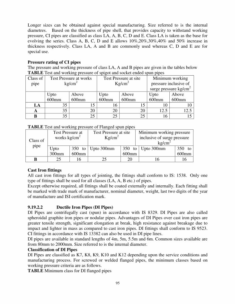
95
Longer sizes can be obtained against special manufacturing. Size referred to is the internal diametres. Based on the thickness of pipe shell, that provides capacity to withstand working pressure, CI pipes are classified as class LA, A, B, C, D and E. Class LA is taken as the base for evolving the series. Class A, B, C, D and E allows 10%,20%,30%,40% and 50% increase in thickness respectively. Class LA, A and B are commonly used whereas C, D and E are for special use. Pressure rating of CI pipes
The pressure and working pressure of class LA, A and B pipes are given in the tables below TABLE Test and working pressure of spigot and socket ended spun pipes Class of
pipe Test Pressure at works
kg/cm2 Test Pressure at site
Kg/cm2 Minimum working
pressure inclusive of surge pressure kg/cm2
Upto 600mm
Above 600mm
Upto 600mm
Above 600mm
Upto 600mm
Above 600mm
LA 35 15 16 15 10 10 A 35 20 20 20 12.5 12.5 B 35 25 25 25 16 15
TABLE Test and working pressure of Flanged spun pipes
Class of pipe
Test Pressure at works kg/cm2
Test Pressure at site Kg/cm2
Minimum working pressure inclusive of surge pressure
kg/cm2 Upto 300mm
350 to 600mm
Upto 300mm 350 to 600mm
Upto 300mm 350 to 600mm
B 25 16 25 20 16 16 Cast Iron fittings
All cast iron fittings for all types of jointing, the fittings shall conform to IS: 1538. Only one type of fittings shall be used for all classes (LA, A, B etc.) of pipes. Except otherwise required, all fittings shall be coated externally and internally. Each fitting shall be marked with trade mark of manufacturer, nominal diameter, weight, last two digits of the year of manufacture and ISI certification mark. 9.19.2.2 Ductile Iron Pipes (DI Pipes)
DI Pipes are centrifugally cast (spun) in accordance with IS 8329. DI Pipes are also called spheroidal graphite iron pipes or nodular pipes. Advantages of DI Pipes over cast iron pipes are greater tensile strength, significant elongation at break, high resistance against breakage due to impact and lighter in mass as compared to cast iron pipes. DI fittings shall conform to IS 9523. CI fittings in accordance with IS 13382 can also be used in DI pipe lines. DI pipes are available in standard lengths of 4m, 5m, 5.5m and 6m. Common sizes available are from 80mm to 2000mm. Size referred to is the internal diameter. Classification of DI Pipes
DI Pipes are classified as K7, K8, K9, K10 and K12 depending upon the service conditions and manufacturing process. For screwed or welded flanged pipes, the minimum classes based on working pressure criteria are as follows. TABLE Minimum class for DI flanged pipes
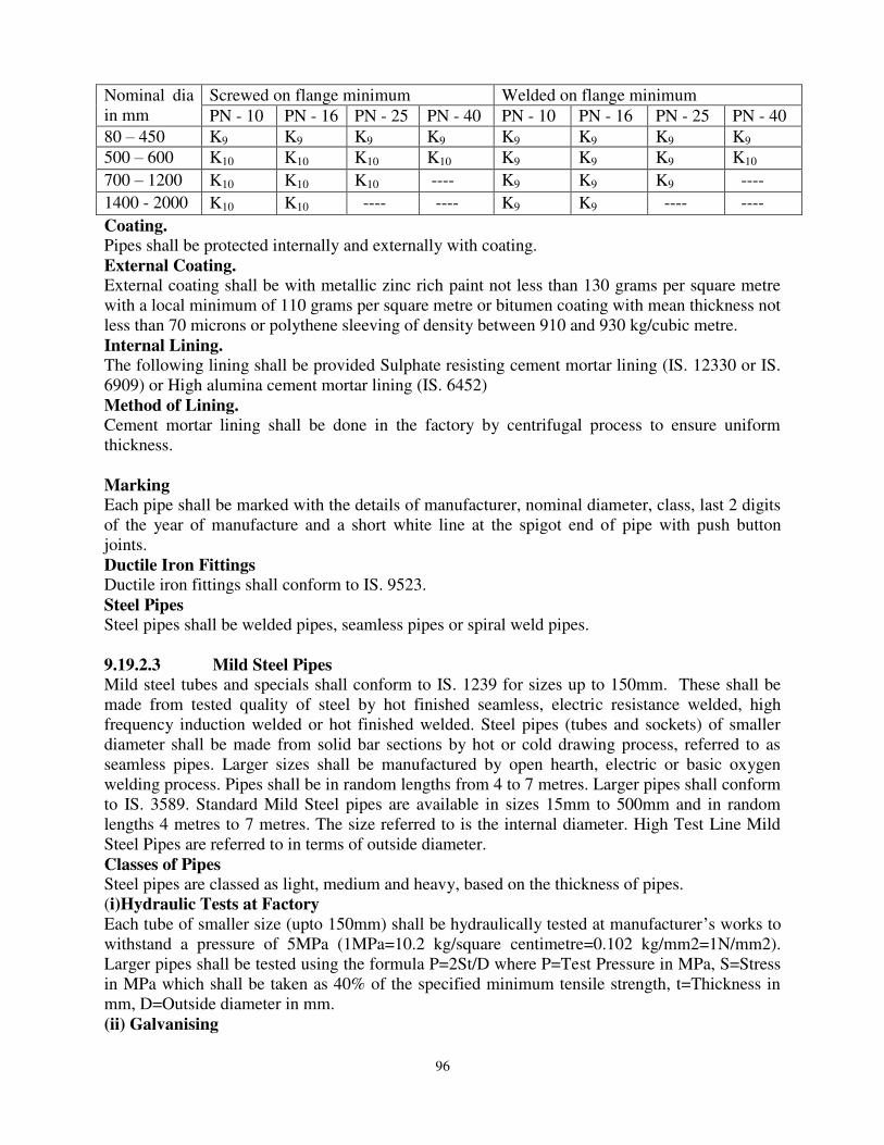
96
Nominal dia in mm
Screwed on flange minimum Welded on flange minimum PN - 10 PN - 16 PN - 25 PN - 40 PN - 10 PN - 16 PN - 25 PN - 40
80 – 450 K9 K9 K9 K9 K9 K9 K9 K9 500 – 600 K10 K10 K10 K10 K9 K9 K9 K10
700 – 1200 K10 K10 K10 ---- K9 K9 K9 ----
1400 - 2000 K10 K10 ---- ---- K9 K9 ---- ----
Coating.
Pipes shall be protected internally and externally with coating. External Coating.
External coating shall be with metallic zinc rich paint not less than 130 grams per square metre with a local minimum of 110 grams per square metre or bitumen coating with mean thickness not less than 70 microns or polythene sleeving of density between 910 and 930 kg/cubic metre. Internal Lining.
The following lining shall be provided Sulphate resisting cement mortar lining (IS. 12330 or IS. 6909) or High alumina cement mortar lining (IS. 6452) Method of Lining.
Cement mortar lining shall be done in the factory by centrifugal process to ensure uniform thickness. Marking
Each pipe shall be marked with the details of manufacturer, nominal diameter, class, last 2 digits of the year of manufacture and a short white line at the spigot end of pipe with push button joints. Ductile Iron Fittings
Ductile iron fittings shall conform to IS. 9523. Steel Pipes
Steel pipes shall be welded pipes, seamless pipes or spiral weld pipes.
9.19.2.3 Mild Steel Pipes
Mild steel tubes and specials shall conform to IS. 1239 for sizes up to 150mm. These shall be made from tested quality of steel by hot finished seamless, electric resistance welded, high frequency induction welded or hot finished welded. Steel pipes (tubes and sockets) of smaller diameter shall be made from solid bar sections by hot or cold drawing process, referred to as seamless pipes. Larger sizes shall be manufactured by open hearth, electric or basic oxygen welding process. Pipes shall be in random lengths from 4 to 7 metres. Larger pipes shall conform to IS. 3589. Standard Mild Steel pipes are available in sizes 15mm to 500mm and in random lengths 4 metres to 7 metres. The size referred to is the internal diameter. High Test Line Mild Steel Pipes are referred to in terms of outside diameter. Classes of Pipes
Steel pipes are classed as light, medium and heavy, based on the thickness of pipes. (i)Hydraulic Tests at Factory
Each tube of smaller size (upto 150mm) shall be hydraulically tested at manufacturer’s works to withstand a pressure of 5MPa (1MPa=10.2 kg/square centimetre=0.102 kg/mm2=1N/mm2). Larger pipes shall be tested using the formula P=2St/D where P=Test Pressure in MPa, S=Stress in MPa which shall be taken as 40% of the specified minimum tensile strength, t=Thickness in mm, D=Outside diameter in mm. (ii) Galvanising
97
When tubes are to be galvanized, the zinc coating shall conform to IS. 4736. (Hot dip zinc coatings on steel tubes.) (iii) Nominal Diameter Nominal diameter or nominal bore of steel pipe is the inner diameter of the pipe. (iv) Markings
Each pipe shall be marked with manufacturer’s name or trade mark, nominal diameter, pipe designation/wall thickness and ISI certification mark. Fittings for Steel Pipes
(v) Screwed fittings
Malleable iron fittings for steel pipes shall conform to IS 1879. Wrought steel fittings shall conform to IS 1239. Threads to these fittings shall be as per IS 554. Galvanising of the special shall be done as stipulated in IS 1239. The specials are manufactured in three grades – light, medium and heavy. After being screwed, the specials should withstand an internal water pressure of 5MPa without any sign of leakage.
(vi) Plane Ended Specials
In case of plain end fittings, wrought steel butt welding fittings are used. Flanges may be screwed or welded type. The contact surface may be plain, serrated and grooved for ring joints. The serrated finish shall be of spiral or concentric grooves, usually about 0.4mm deep with 12 serrations per centimetre. The flanges shall conform to IS 6392. The bolts and nuts shall be in accordance with IS 1364. (vii) Protection against corrosion
Against internal corrosion, steel pipes shall be given epoxy lining or hot applied coal tar/asphalt lining or rich cement mortar lining at works or in field by centrifuging. Outer coating for underground pipe line shall be in cement – sand guniting or hot applied coal tar asphaltic enamel reinforced with fibre-glass fabric yarn. The protective coating shall be in accordance with IS. 10221. 19.19.2.4 Concrete Pipes
Concrete pipes are manufactured conforming to IS.458, by centrifugal (spun) process. Concrete pipes shall be manufactured with or without reinforcement. These pipes are available in lengths 2, 2.5 and 3metres. Size referred to is the internal diameter. Classification of pipes
Concrete pipes are classified as non–pressure pipes and pressure pipes. Non pressure pipes are referred to as NP and pressure pipes as P. There are 4 classes of non-pressure pipes, used for different purposes, as shown below. TABLE Classification and use of non-pressure concrete pipes. Class Description Use
CLASS Description Use NP1 Unreinforced For drainage and irrigation NP2 Reinforced, Light duty For culverts carrying light traffic NP3 Reinforced, Medium duty For culverts carrying Medium traffic NP4 Reinforced, Heavy duty For drainage and irrigation use and
culverts carrying heavy traffic There are 3 classes of pressure pipes used for water supply.
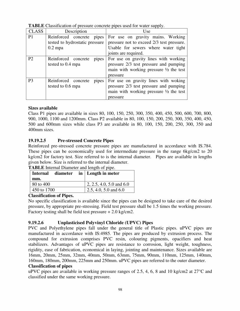
98
TABLE Classification of pressure concrete pipes used for water supply. CLASS Description Use P1 Reinforced concrete pipes
tested to hydrostatic pressure 0.2 mpa
For use on gravity mains. Working pressure not to exceed 2/3 test pressure. Usable for sewers where water tight joints are required.
P2 Reinforced concrete pipes tested to 0.4 mpa
For use on gravity lines with working pressure 2/3 test pressure and pumping main with working pressure ½ the test pressure
P3 Reinforced concrete pipes tested to 0.6 mpa
For use on gravity lines with woking pressure 2/3 test pressure and pumping main with working pressure ½ the test pressure
Sizes available
Class P1 pipes are available in sizes 80, 100, 150, 250, 300, 350, 400, 450, 500, 600, 700, 800, 900, 1000, 1100 and 1200mm. Class P2 available in 80, 100, 150, 200, 250, 300, 350, 400, 450, 500 and 600mm sizes while class P3 are available in 80, 100, 150, 200, 250, 300, 350 and 400mm sizes. 19.19.2.5 Pre-stressed Concrete Pipes
Reinforced pre-stressed concrete pressure pipes are manufactured in accordance with IS.784. These pipes can be economically used for intermediate pressure in the range 6kg/cm2 to 20 kg/cm2 for factory test. Size referred to is the internal diameter. Pipes are available in lengths given below. Size is referred to the internal diameter. TABLE Internal Diameter and length of pipe.
Internal diameter in
mm. Length in meter
80 to 400 2, 2.5, 4.0, 5.0 and 6.0 450 to 1700 2.5, 4.0, 5.0 and 6.0
Classification of Pipes.
No specific classification is available since the pipes can be designed to take care of the desired pressure, by appropriate pre-stressing. Field test pressure shall be 1.5 times the working pressure. Factory testing shall be field test pressure + 2.0 kg/cm2. 9.19.2.6 Unplasticised Polyvinyl Chloride (UPVC) Pipes
PVC and Polyethylene pipes fall under the general title of Plastic pipes. uPVC pipes are manufactured in accordance with IS:4985. The pipes are produced by extrusion process. The compound for extrusion comprises PVC resin, colouring pigments, opacifiers and heat stabilizers. Advantages of uPVC pipes are resistance to corrosion, light weight, toughness, rigidity, ease of fabrication, economical in laying, jointing and maintenance. Sizes available are 16mm, 20mm, 25mm, 32mm, 40mm, 50mm, 63mm, 75mm, 90mm, 110mm, 125mm, 140mm, 160mm, 180mm, 200mm, 225mm and 250mm. uPVC pipes are referred to the outer diameter. Classification of pipes
uPVC pipes are available in working pressure ranges of 2.5, 4, 6, 8 and 10 kg/cm2 at 27°C and classified under the same working pressure.
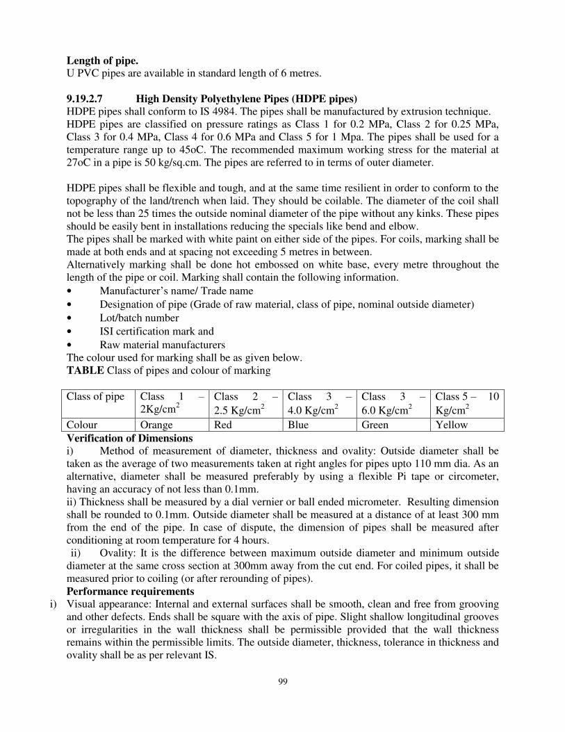
99
Length of pipe. U PVC pipes are available in standard length of 6 metres.
9.19.2.7 High Density Polyethylene Pipes (HDPE pipes)
HDPE pipes shall conform to IS 4984. The pipes shall be manufactured by extrusion technique. HDPE pipes are classified on pressure ratings as Class 1 for 0.2 MPa, Class 2 for 0.25 MPa, Class 3 for 0.4 MPa, Class 4 for 0.6 MPa and Class 5 for 1 Mpa. The pipes shall be used for a temperature range up to 45oC. The recommended maximum working stress for the material at 27oC in a pipe is 50 kg/sq.cm. The pipes are referred to in terms of outer diameter. HDPE pipes shall be flexible and tough, and at the same time resilient in order to conform to the topography of the land/trench when laid. They should be coilable. The diameter of the coil shall not be less than 25 times the outside nominal diameter of the pipe without any kinks. These pipes should be easily bent in installations reducing the specials like bend and elbow. The pipes shall be marked with white paint on either side of the pipes. For coils, marking shall be made at both ends and at spacing not exceeding 5 metres in between. Alternatively marking shall be done hot embossed on white base, every metre throughout the length of the pipe or coil. Marking shall contain the following information. • Manufacturer’s name/ Trade name • Designation of pipe (Grade of raw material, class of pipe, nominal outside diameter) • Lot/batch number • ISI certification mark and • Raw material manufacturers The colour used for marking shall be as given below. TABLE Class of pipes and colour of marking Class of pipe Class 1 –
2Kg/cm2 Class 2 –
2.5 Kg/cm2
Class 3 –
4.0 Kg/cm2
Class 3 –
6.0 Kg/cm2
Class 5 – 10
Kg/cm2
Colour Orange Red Blue Green Yellow Verification of Dimensions
i) Method of measurement of diameter, thickness and ovality: Outside diameter shall be taken as the average of two measurements taken at right angles for pipes upto 110 mm dia. As an alternative, diameter shall be measured preferably by using a flexible Pi tape or circometer, having an accuracy of not less than 0.1mm. ii) Thickness shall be measured by a dial vernier or ball ended micrometer. Resulting dimension shall be rounded to 0.1mm. Outside diameter shall be measured at a distance of at least 300 mm from the end of the pipe. In case of dispute, the dimension of pipes shall be measured after conditioning at room temperature for 4 hours. ii) Ovality: It is the difference between maximum outside diameter and minimum outside
diameter at the same cross section at 300mm away from the cut end. For coiled pipes, it shall be measured prior to coiling (or after rerounding of pipes). Performance requirements
i) Visual appearance: Internal and external surfaces shall be smooth, clean and free from grooving and other defects. Ends shall be square with the axis of pipe. Slight shallow longitudinal grooves or irregularities in the wall thickness shall be permissible provided that the wall thickness remains within the permissible limits. The outside diameter, thickness, tolerance in thickness and ovality shall be as per relevant IS.

100
ii) Hydraulic characteristics: When subjected to internal pressure creep rupture test, the pipes shall not show signs of localised swelling, leakage or weeping and shall not burst during the test duration. The temperature, duration of test and induced stress for the test shall be as per details given in the table below: TABLE Type of Test, Temperature, Duration of Test and Induced Stress for Test
Sl. No
Test Temperat
ure 0C
Test Duration (Minimum
holding time in Seconds)
Induce Stress (MPa) PE 63 PE 90 PE 110
1 Type test 80 165 3.50 4.60 5.50 2 Acceptance Test 80 48 3.80 4.90 5.70
The internal test pressure for the above test shall be calculated by adopting the formula given below P= 2 x p x s --------------- (d---s) where p=test pressure in MPa s=minimum wall thickness in mm d=outside diameter in mm P=induced stress in MPa as given in the table above
iii) Reversion test: Longitudinal reversion shall not be greater than 3% iv) Overall migration test: When tested from a composite sample of minimum of 3 pipes as per IS 9845, the overall migration of constituents shall be within the limits specified in IS 10146.
v) Density: Composite sample of minimum of 3 pipes as per IS 7328 shall have a density of 940.3-946.4 kg/ cu m at 27 deg C. The value of density shall not differ from the nominal value by more than 3 kg/cu.m as per clause 5.2.1.1of IS 7328.
vi) Melt flow rate (MFR): Composite sample of minimum of 3 pipes as per IS 2530 at 190 deg C with nominal load of 5 kgf , MFR shall be 0.4 -1.1 g/ 10cminutes and also shall not differ by more than 30% of the material used in manufacturing of pipes. The MFR of the material shall be 0.41-1.10g/10cminutes when tested at 190deg C with nominal load of 5kgpf as determined by method prescribed in 7 of IS 2530. The MFR of the material shall becwithin +20% of the value declared by the manufacturer
vii) Carbon black content and dispersion: For composite sample of minimum of 3 samples in accordance with IS 2530, the carbon black content shall be within 2.5+ 0.5%and the dispersion of carbon black shall be satisfactory. Sampling, frequency of tests and criteria for conformity for acceptance tests:
i) Lot: It shall consist of same size, same pressure rating, same grade and manufactured essentially under similar conditions. The number of samples to be collected for various tests based on the size of lot shall be as per the table given below .The pipes shall be selected at random for sampling. Starting from any pipe in the lot, count them as 1,2,3,4 etc upto ‘r ‘and so on where ‘r’ is the integral part of N/n, N being the number of pipes in the lot and ‘n’ is the number of pipes in the sample. Every Rth pipe so counted shall be drawn as to constitute the required sample size. TABLE Sample Size, Acceptance Criteria
Number of pipes in lot
Sample number
Sample Size
Cumulative sample size
Acceptance number
Rejection number
1 2 3 4 5 6 Upto 150 First 13 13 0 2

101
Second 13 26 1 2
151-280 First 20 20 0 3 Second 20 40 3 4
281-500 First 32 32 1 4 Second 32 64 4 5
501 – 1200 First 50 50 2 5 Second 50 100 6 7
1201 – 3200 First 80 80 3 7 Second 80 160 8 9
3201 -10000 First 125 125 8 9 Second 125 250 12 13
10001 - 35000 First 200 200 7 11 Second 200 400 18 19
ii) Visual and dimensions: They shall be checked from the first sample size. Pipes failing to satisfy any of the requirements shall be considered as defective. The lot is satisfied if the number of defectives found in the first sample are less than or equal to the corresponding number given in column 6 of the table .The lot is defective if the number of defectives is greater than the number in rejection number. If the defectives number is between columns ‘5’and ‘6’, the second sample of sizes shall be taken and examined .The lot is considered satisfactory, if the number of defectives found in the cumulative sample is less than or equal to the corresponding acceptance number. Otherwise it is considered not satisfactory. iii) Hydraulic characteristics, reversion, overall migration, MFR and carbon black /
dispersion tests:
The lot having satisfied visual and dimensional requirements only shall be taken up for further testing. A separate sample size for each of the tests shall be taken as stipulated below and selected at random from the sample already examined for visual and dimensional inspection.
No of pipes Sample size Upto 150 pipes 3 151-1200 pipes 5
All the pipes in the sample shall be tested for requirements .The lot shall be considered satisfactory if none of the samples tested fails. Transporting And Handling Pipes, Specials and Appurtenances.
Transporting and handling:
Pipes and fittings must not be dropped, indented, crushed or impacted. Particular care should be taken to avoid scoring, scrapping and abrasion damage. Scores or scratches to a depth of 10% or more of wall thickness are sufficient to require rejection of the pipes and fittings. Pipes must not be stored or transported where they are exposed to heat sources likely to exceed 70° C e.g., vehicle exhaust gases. Safety Precautions:
i) PE particles can be abrasive if they enter eyes ii) Molten PE produced by welding operation will adhere strongly to the skin in the event of accidental contact. Should this occur, the affected part should be flooded with cold water. The molten or solidified material should not be removed from the skin and medical assistance should be obtained even for small burns. iii) Molten PE will yield a small quantity of fume especially at high temperatures. Work areas where welding is being carried out should be ventilated for safe working conditions.
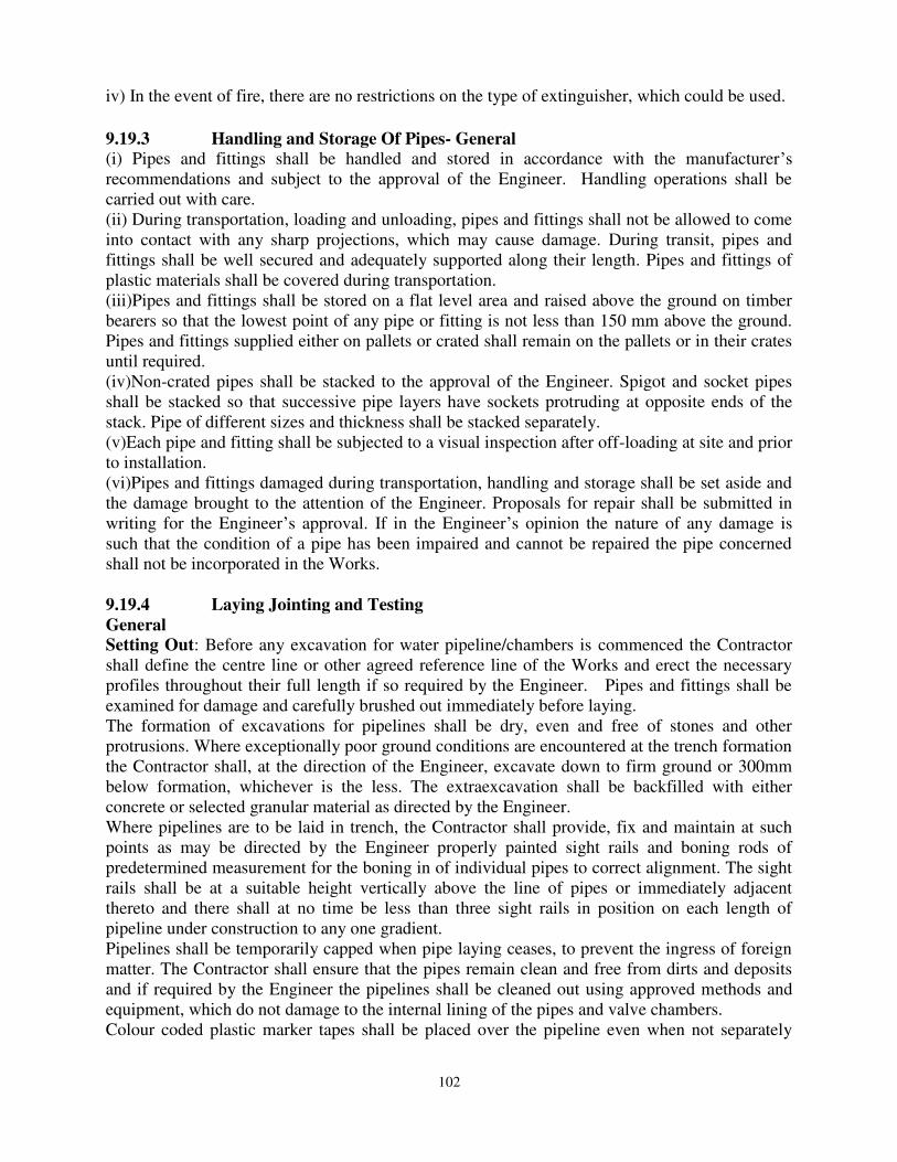
102
iv) In the event of fire, there are no restrictions on the type of extinguisher, which could be used.
9.19.3 Handling and Storage Of Pipes- General
(i) Pipes and fittings shall be handled and stored in accordance with the manufacturer’s recommendations and subject to the approval of the Engineer. Handling operations shall be carried out with care. (ii) During transportation, loading and unloading, pipes and fittings shall not be allowed to come into contact with any sharp projections, which may cause damage. During transit, pipes and fittings shall be well secured and adequately supported along their length. Pipes and fittings of plastic materials shall be covered during transportation. (iii)Pipes and fittings shall be stored on a flat level area and raised above the ground on timber bearers so that the lowest point of any pipe or fitting is not less than 150 mm above the ground. Pipes and fittings supplied either on pallets or crated shall remain on the pallets or in their crates until required. (iv)Non-crated pipes shall be stacked to the approval of the Engineer. Spigot and socket pipes shall be stacked so that successive pipe layers have sockets protruding at opposite ends of the stack. Pipe of different sizes and thickness shall be stacked separately. (v)Each pipe and fitting shall be subjected to a visual inspection after off-loading at site and prior to installation. (vi)Pipes and fittings damaged during transportation, handling and storage shall be set aside and the damage brought to the attention of the Engineer. Proposals for repair shall be submitted in writing for the Engineer’s approval. If in the Engineer’s opinion the nature of any damage is such that the condition of a pipe has been impaired and cannot be repaired the pipe concerned shall not be incorporated in the Works. 9.19.4 Laying Jointing and Testing
General
Setting Out: Before any excavation for water pipeline/chambers is commenced the Contractor shall define the centre line or other agreed reference line of the Works and erect the necessary profiles throughout their full length if so required by the Engineer. Pipes and fittings shall be examined for damage and carefully brushed out immediately before laying. The formation of excavations for pipelines shall be dry, even and free of stones and other protrusions. Where exceptionally poor ground conditions are encountered at the trench formation the Contractor shall, at the direction of the Engineer, excavate down to firm ground or 300mm below formation, whichever is the less. The extraexcavation shall be backfilled with either concrete or selected granular material as directed by the Engineer. Where pipelines are to be laid in trench, the Contractor shall provide, fix and maintain at such points as may be directed by the Engineer properly painted sight rails and boning rods of predetermined measurement for the boning in of individual pipes to correct alignment. The sight rails shall be at a suitable height vertically above the line of pipes or immediately adjacent thereto and there shall at no time be less than three sight rails in position on each length of pipeline under construction to any one gradient. Pipelines shall be temporarily capped when pipe laying ceases, to prevent the ingress of foreign matter. The Contractor shall ensure that the pipes remain clean and free from dirts and deposits and if required by the Engineer the pipelines shall be cleaned out using approved methods and equipment, which do not damage to the internal lining of the pipes and valve chambers. Colour coded plastic marker tapes shall be placed over the pipeline even when not separately
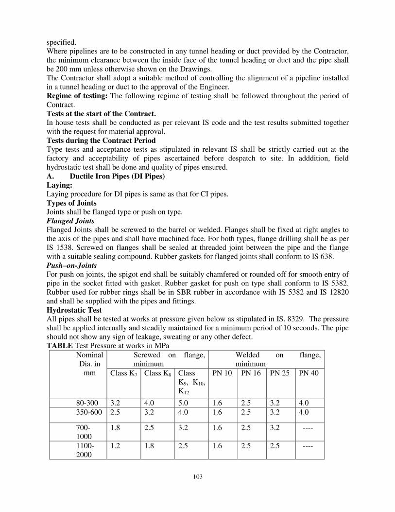
103
specified. Where pipelines are to be constructed in any tunnel heading or duct provided by the Contractor, the minimum clearance between the inside face of the tunnel heading or duct and the pipe shall be 200 mm unless otherwise shown on the Drawings. The Contractor shall adopt a suitable method of controlling the alignment of a pipeline installed in a tunnel heading or duct to the approval of the Engineer. Regime of testing: The following regime of testing shall be followed throughout the period of Contract. Tests at the start of the Contract.
In house tests shall be conducted as per relevant IS code and the test results submitted together with the request for material approval. Tests during the Contract Period
Type tests and acceptance tests as stipulated in relevant IS shall be strictly carried out at the factory and acceptability of pipes ascertained before despatch to site. In adddition, field hydrostatic test shall be done and quality of pipes ensured. A. Ductile Iron Pipes (DI Pipes)
Laying:
Laying procedure for DI pipes is same as that for CI pipes. Types of Joints
Joints shall be flanged type or push on type. Flanged Joints Flanged Joints shall be screwed to the barrel or welded. Flanges shall be fixed at right angles to the axis of the pipes and shall have machined face. For both types, flange drilling shall be as per IS 1538. Screwed on flanges shall be sealed at threaded joint between the pipe and the flange with a suitable sealing compound. Rubber gaskets for flanged joints shall conform to IS 638. Push–on-Joints
For push on joints, the spigot end shall be suitably chamfered or rounded off for smooth entry of pipe in the socket fitted with gasket. Rubber gasket for push on type shall conform to IS 5382. Rubber used for rubber rings shall be in SBR rubber in accordance with IS 5382 and IS 12820 and shall be supplied with the pipes and fittings. Hydrostatic Test
All pipes shall be tested at works at pressure given below as stipulated in IS. 8329. The pressure shall be applied internally and steadily maintained for a minimum period of 10 seconds. The pipe should not show any sign of leakage, sweating or any other defect. TABLE Test Pressure at works in MPa
Nominal Dia. in
mm
Screwed on flange, minimum
Welded on flange, minimum
Class K7 Class K8 Class K9, K10, K12
PN 10 PN 16 PN 25 PN 40
80-300 3.2 4.0 5.0 1.6 2.5 3.2 4.0 350-600 2.5 3.2 4.0 1.6 2.5 3.2 4.0
700-1000
1.8 2.5 3.2 1.6 2.5 3.2 ----
1100-2000
1.2 1.8 2.5 1.6 2.5 2.5 ----
104
B. Steel Pipes
Laying
Steel pipes shall be laid as specified in IS. 5822. Pipes shall be inspected for defects such as protrusion, grooves, dents, notches etc and if found they shall be rectified. Defect free pipes shall be lowered in the trenches. The procedure for lowering varies with the method adopted for coating the pipes. Care shall be taken to see that longitudinal welded joints of consecutive pipes are staggered by at least 30° and shall be kept in upper third of the pipe line. Pipes laid above ground may be allowed to rest on the ground if the soil is not aggressive. The ground should however be dressed to match the curvature of the pipe shell for an arch length subtending an angle of 120° at the centre of the pipe. For all pipe lines laid above ground provision shall be made to contain expansion and contraction on account of temperature variation. Expansion joints or loops shall be provided at pre-determined points. Testing
The pipes in test length shall be slowly filled with water and air shall be expelled. The field test pressure shall not be less than the greatest of the following. a. Maximum sustained operating pressure b. Maximum static pressure c. Sum of the maximum of (a) and (b) and surge pressure. Where the working pressure is less than two-third of the test pressure in the case of gravity main or half the test pressure in the case of pumping main, the test pressure shall be maintained at least for 24 hours. Further the leakage during the test shall also be within the prescribed limit. If the pressure drops, water shall be pumped in to maintain the test pressure and the quantity of water thus pumped shall be carefully measured. The quantity should not exceed 0.1 lit / millimeter of pipe diameter per kilometer of pipe line length for each 30 metres of head applied. Jointing.
Following are the types of joints provided in steel pipes. (a) Threaded joints (Screwed joints) (b) Sleeved pipes by fillet weld (c) Plain end pipe by butt weld (d) Flanged joint (Bolted joints) Threaded joints are given to the smaller pipes. Threads of all screwed ends and socket (coupling) shall conform to IS. 554. Each screwed joint pipe shall be supplied with one socket as an integral part of the supply. Larger pipes shall have welded joints. Sleeved pipes with fillet weld shall be as specified in IS. 3589. Plain end but welding shall be as per IS. 3589. Flanged joints are used wherever required. The flanges shall conform to IS. 1538. When tubes are required to be galvanized the zinc coating shall be in accordance with IS. 4736.
C . Concrete Pipes
.Pipes are jointed with rubber gaskets and provide flexible joints as per IS.784. Pipes are provided with spigot and socket ends to enable jointing with rubber gaskets. The rubber gaskets shall conform to IS.5382.
D. Prestressed Concrete Pipes (PSC Pipes)
Jointing

105
All non-pressure pipes shall have flexible rubber ring joints in accordance with IS.783. Pressure pipes shall have rigid collar joints, semi flexible collar joints, rigid spigot and socket joints or semi flexible spigot and socket joints. Collar Joints: Collars are 15 to 20 cm wide. A mixture of cement and sand in the ratio 1:1.5 is rammed along with caulking iron to form the joint. The joint shall be kept wet for 10 days for maturing. E. Plastic Pipes
(i).Storage
Pipe packs should be placed on timber bearers approximately 2m c/c. Avoid long term stacking of pipes. Providing proper regard is given to sideways stability (ex: wind forces), packs which are usually 1.2 meters wide may be stacked up to 3m in height for straight pipes. Coils stacked horizontally shall be placed on pallets for convenient lifting or slinging and the height of coils shall be limited to 1.0m in height. Lifting and unloading
Metal hooks, chains or slings must not be used without padding for lifting coils or pipes. Care shall be taken to avoid injury to personnel when cutting the steel restraining bands on coils. (ii)Laying
1. In sufficient time before commencement of the Works, the Contractor shall submit for the Engineer’s approval the pipe manufacturer’s complete and detailed specification for the handling and installation of pipes and fittings in open trench and such other methods of construction of pipeline specified or proposed by the Contractor, irrespective of whether the data was submitted with the tender.
2. The Contractor shall lay pipes in accordance with the approved manufacturer’s installation specification as approved by the Engineer after submission and acceptance of appropriate quality control test results.
3. The Contractor shall use a suitable mechanised device to the approval of the Engineer for gauging pipe deflections both before and after laying, in the stages specified.
4. For pipes of less than 600mm diameter, a deflectometer of a form that can be drawn through the pipeline and capable of measuring diametric dimensions both vertically and horizontally shall be provided by the Contractor. It shall be calibrated for each diameter regularly in the presence of the Engineer to maintain the accuracy of the instrument. The device shall also provide a means of identifying where each deflection measurement was taken along the length of the pipeline. This shall be either in the form of a continuous print out or in the form of a visual display or a remote monitor.
5. When instructed by the Engineer, the Contractor shall also provide pipe deflection measuring equipment in full working order for use of the Engineer or the Employer. 6. The pipes shall be laid and bedded in a granular material as specified elsewhere except where concrete protection is required. Trenches shall be excavated to depth 150 mm below the underside of the pipe.
7. The granular material shall be placed over the full width of the bottom of the trench to the level of the underside of the pipe and shall be compacted as required for that class of bedding material. Suitable depressions shall be made in the bed to accommodate the pipe joints and shall be of minimum width and depth practicable. The trench shall be carefully filled to 300 mm above the crown of the pipe in layers not exceeding 150mm. Particular care shall be taken to ensure that the depressions for the joints are completely filled and that the bedding material is well compacted under the haunches of the pipe over the full length of the pipeline.
8. The Engineer may, from time to time, require that tests are carried out on the bedding to
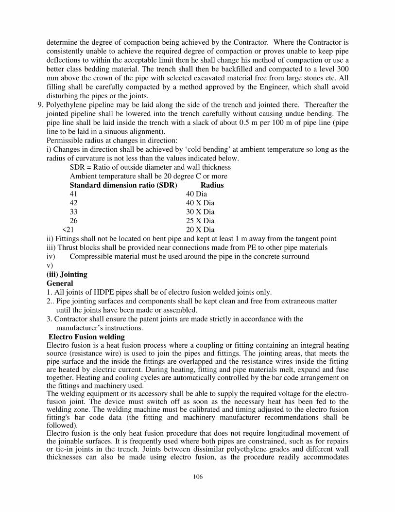
106
determine the degree of compaction being achieved by the Contractor. Where the Contractor is consistently unable to achieve the required degree of compaction or proves unable to keep pipe deflections to within the acceptable limit then he shall change his method of compaction or use a better class bedding material. The trench shall then be backfilled and compacted to a level 300 mm above the crown of the pipe with selected excavated material free from large stones etc. All filling shall be carefully compacted by a method approved by the Engineer, which shall avoid disturbing the pipes or the joints.
9. Polyethylene pipeline may be laid along the side of the trench and jointed there. Thereafter the jointed pipeline shall be lowered into the trench carefully without causing undue bending. The pipe line shall be laid inside the trench with a slack of about 0.5 m per 100 m of pipe line (pipe line to be laid in a sinuous alignment). Permissible radius at changes in direction: i) Changes in direction shall be achieved by ‘cold bending’ at ambient temperature so long as the radius of curvature is not less than the values indicated below.
SDR = Ratio of outside diameter and wall thickness Ambient temperature shall be 20 degree C or more Standard dimension ratio (SDR) Radius
41 40 Dia 42 40 X Dia 33 30 X Dia 26 25 X Dia
<21 20 X Dia ii) Fittings shall not be located on bent pipe and kept at least 1 m away from the tangent point iii) Thrust blocks shall be provided near connections made from PE to other pipe materials iv) Compressible material must be used around the pipe in the concrete surround v) (iii) Jointing
General
1. All joints of HDPE pipes shall be of electro fusion welded joints only. 2.. Pipe jointing surfaces and components shall be kept clean and free from extraneous matter until the joints have been made or assembled. 3. Contractor shall ensure the patent joints are made strictly in accordance with the manufacturer’s instructions. Electro Fusion welding Electro fusion is a heat fusion process where a coupling or fitting containing an integral heating source (resistance wire) is used to join the pipes and fittings. The jointing areas, that meets the pipe surface and the inside the fittings are overlapped and the resistance wires inside the fitting are heated by electric current. During heating, fitting and pipe materials melt, expand and fuse together. Heating and cooling cycles are automatically controlled by the bar code arrangement on the fittings and machinery used. The welding equipment or its accessory shall be able to supply the required voltage for the electro-fusion joint. The device must switch off as soon as the necessary heat has been fed to the welding zone. The welding machine must be calibrated and timing adjusted to the electro fusion fitting's bar code data (the fitting and machinery manufacturer recommendations shall be followed). Electro fusion is the only heat fusion procedure that does not require longitudinal movement of the joinable surfaces. It is frequently used where both pipes are constrained, such as for repairs or tie-in joints in the trench. Joints between dissimilar polyethylene grades and different wall thicknesses can also be made using electro fusion, as the procedure readily accommodates
107
polyethylene grades with different melt flow rates and is independent of the pipe wall thickness. Electro Fusion Welding Procedure a) Prepare the pipe - Cut at right angles and trim, b) Remove the outer film of pipes using scraper,
c) Clean pipe surfaces with cleaner (as recommended by the Electro Fusion fittings supplier), d) Mark the insertion depth on the pipe, e) Remove the fittings from the packaging without touching the fusion surface, f) Firmly push-in the pipe until the center stop or marking, g) Mount and fix assembly attachment, h) Slide in the second pipe up into the fitting to center stop or marking, i) Firmly fasten the integrated clamp to ensure no movement while welding, j) Follow operating instructions of the machine and fitting manufacturer or read the bar code. k) Check the fusion indicator on the fittings and then remove cable. And l) Wait for cooling to remove the assembly (follow the fusion guidelines of the fusion fittings supplier or what is given in the bar code data).
9.19.5 Installation of underground services warning tape
Services protection tapes shall be installed above all water pipeline mains constructed or exposed under this Contract excluding individual service connections. For pipeline with top of the pipe barrel more than 900mm below finished surface level the tape shall be placed over the centerline of the pipe line at 600mm below finished surface level during backfilling and compaction operation. For pipelines with less than 900mm cover to the top of the pipe barrel the tape shall be placed over the centerline of the pipe at 300mm above the top of the pipe barrel during backfilling, compaction and reinstatement operations. The tape shall be continuous over pipelines and at joints between taps from separate rolls the joint shall be lapped a minimum of one metre. The cost of providing warning tapes is deemed to be included in the quotable items unless otherwise specified in specif items of bill of quantities.
9.19.6 (I) Customer Water Meters
A. General
The meters procured will be used for measurement of cold, chlorinated potable water and will be installed just above the ground level. The meters will be installed the CMC city in the State of Karnataka, India. The meters should with stand the natural wear and tear that is expected due to rain or sun in these places. All the meters supplied shall be suitable for indefinite immersion under water compliant with IP 68. The warranty for customer water meters is for sixty months from the date of installation of water meters. The water meters shall be packed taking all precautions so that they are not damaged during the transport in containers or boxes containing not more than fifty (50) meters each. Any water meters that are damaged at the time of receipt at the purchasers store* will not be considered for payment. B. Applicable Standards Meters shall conform to latest versions of IS 779 or ISO 4064 Standards C. Meter Type The meters shall be: i) Multi- jet

108
ii) Inferential/Velocity meters iii) Super Dry dial iv) Hermitically sealed v) Class B vi) Nominal size of water meters shall be 15mm D Materials All the materials used to construct/manufacture customer meters shall confirm to Appendix B of IS 779 or clause 4.7 of ISO - 4064-1. In particular the following.
i. Body shall be either Bronze and Brass ii. The totalizer shield shall be enclosed in a copper can.
iii. Lid shall be made of bronze, brass, plastic or stainless steel. iv. Cap and cap ring shall be made of engineering plastic. v. Registration box can be made of plastic.
vi. Screws & studs shall be made high tensile brass or superior material vii. Strainers shall be made of plastics or superior material
viii. Impeller shall be made of plastics or superior material ix. Impeller shaft shall be of either stainless steel or high tensile brass x. Nipples and nuts shall be of same materials as that of body of the meter
xi. Measuring chamber shall be of the same materials as that of body of the meter xii. The spindle and bearings inside the hydraulic chamber shall be made of polished
Stainless Steel with hard metal tip and sapphire. E. Construction
Meter construction shall be as per clause 7 of IS779 or relevant clauses of ISO 4064 | Each meter should be supplied with two cylindrical nipples or tail pieces with connecting nuts. Threads on the connection shall conform to latest version of IS 2634 (part 1 to 3) or ISO 228-1. All meters shall be supplied with an easily removable tubular inlet strainer. The sealing wires shall be of rust proof material F. Indicating Device
The totalizer shall be designed in such a way that if the totalizer protective glash . • broken for any reason the tantalizer unit cannot be removed from its place. [■.,-. tantalizer protective cover shall be made of mineral glass and shall have a thickness >,\ not less than 12mm. The tantalizer shall be: i) It shall be set at Zero at the factory, excepting the volume registered while testify the meters at the factory. ii) It shall consist of a row of minimum four on-line consecutive digits to read <j least 9.999 m3 or Kl. Meter may have another three digits or pointers which Shfcl register flows in liters. G. Meter - Size and Overall dimensions
Nominal diameter of the meters shall be 15mm Meter threads, nominal flow rate, minimum length of threads on either side, overall dimensions shall be as per Table 2 of IS 779 or Table 1 of ISO 4064 -1. H. Technical Characteristics
All Meters shall be of PN 10 pressure rating. The meters shall be capable of operating in ambient temperatures upto 50°C. The maximum permissible pressure loss through the water meters shall be: i) At Qn 0.025 mpa ii)At Qmax 0.10 mpa
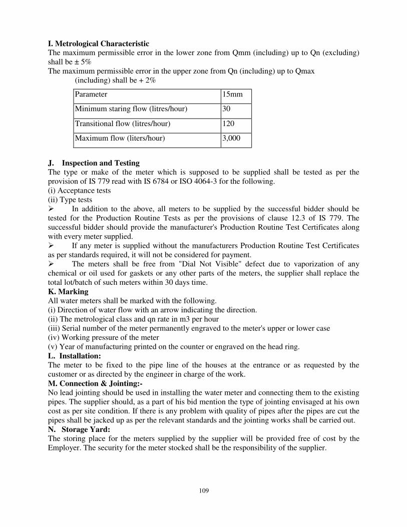
109
I. Metrological Characteristic The maximum permissible error in the lower zone from Qmm (including) up to Qn (excluding) shall be ± 5% The maximum permissible error in the upper zone from Qn (including) up to Qmax
(including) shall be + 2%
Parameter 15mm
Minimum staring flow (litres/hour) 30
Transitional flow (litres/hour) 120
Maximum flow (liters/hour) 3,000
J. Inspection and Testing
The type or make of the meter which is supposed to be supplied shall be tested as per the provision of IS 779 read with IS 6784 or ISO 4064-3 for the following. (i) Acceptance tests (ii) Type tests In addition to the above, all meters to be supplied by the successful bidder should be tested for the Production Routine Tests as per the provisions of clause 12.3 of IS 779. The successful bidder should provide the manufacturer's Production Routine Test Certificates along with every meter supplied. If any meter is supplied without the manufacturers Production Routine Test Certificates as per standards required, it will not be considered for payment. The meters shall be free from "Dial Not Visible" defect due to vaporization of any chemical or oil used for gaskets or any other parts of the meters, the supplier shall replace the total lot/batch of such meters within 30 days time. K. Marking
All water meters shall be marked with the following. (i) Direction of water flow with an arrow indicating the direction. (ii) The metrological class and qn rate in m3 per hour (iii) Serial number of the meter permanently engraved to the meter's upper or lower case (iv) Working pressure of the meter (v) Year of manufacturing printed on the counter or engraved on the head ring. L. Installation:
The meter to be fixed to the pipe line of the houses at the entrance or as requested by the customer or as directed by the engineer in charge of the work. M. Connection & Jointing:-
No lead jointing should be used in installing the water meter and connecting them to the existing pipes. The supplier should, as a part of his bid mention the type of jointing envisaged at his own cost as per site condition. If there is any problem with quality of pipes after the pipes are cut the pipes shall be jacked up as per the relevant standards and the jointing works shall be carried out. N. Storage Yard:
The storing place for the meters supplied by the supplier will be provided free of cost by the Employer. The security for the meter stocked shall be the responsibility of the supplier.
110
9.19.7 Valves
9.19.7.1 General
Flanges of valves shall be drilled to IS. 1538. A complete set of bolts and nuts and one gasket shall be supplied to each flange. The valves shall be capable of withstanding the specified test pressures of the pipeline and be suitable for the conveyance of water of specified quality. All valves shall be protected for corrosive environment. 9.19.7.2 Sluice Valves
Sluice valves shall comply with IS 14846 and be flanged unless otherwise stated and be tested to the requirements of Class 1. Maximum Differential Pressure and Maximum Working Pressure shall be as per relevant IS standards. Sluice valves shall be of the double-flanged ductile iron wedge-gate type and shall have non-rising spindles unless otherwise specified or shown on the Drawings. They shall have a cast iron body with renewable gunmetal faces on body and wedge and bolt-on cast iron bonnet. Rising stem valves shall also incorporate a combined yoke. Where sluice valves above 350 mm bore are mounted with the spindle in the horizontal place the valve body shall be fitted with renewable gunmetal machined gage slides and the gates with renewable hard bronze shoes accurately machined to reduce sliding friction. A sluice valve above 500 mm bore (300 mm if power actuated) shall be provided with jacking screws and valves above 350 mm bore where mounted in a horizontal pipeline shall be provided with feet. Unless otherwise specified each valve shall be provided with a suitable hand wheel of adequate diameter for the duty required and gearing shall be supplied where necessary to ensure that the required operating force applied by hand to the rim of the wheel does not exceed 25Kgf. Hand wheels shall have smooth rims and the direction of closing which shall be clockwise shall be cast on them. Vandal and weatherproof clear polycarbonate tube covers shall be securely fitted to protect the threads of rising stems and spindles and tubes shall be clearly and permanently engraved to indicate the position of the valve. Valve stems shall be of gorged aluminium bronze or stainless steel machined all over and with a machine cut robust trapezoidal or square form thread operating in a gunmetal nut. Stem seals shall be of the stuffing box and gland form arranged for easy replacement of packing and shall be accessible for maintenance without removal of the valve from service. Extension spindles headstocks and foot brackets shall be provided where specified. Where possible providing the valve is not subject to submergence. The extension spindle shall be of the non-rising type and a cast iron bridle piece or similar shall be incorporated on valves of the rising spindle type for this purpose. Where rising stem valves are subject to submergence the extension spindle shall also be of the rising type with the threaded portion positioned above top water level. Extended spindle installations shall include all necessary brackets intermediate supports etc. Headstocks for non-rising spindle installations shall incorporate a valve position indicator. Extension spindles shall be of stainless steel or manganese steel and shall conform with the requirements of valve stems with the exception of non-threaded sections which may be of mild steel. Extension spindle couplings shall be of the muff type and shall be drilled and provided with a nut and bolt for securing the spindle to the valve stem, which shall likewise be drilled to accept the bolt. Extended spindle installations of the rising type shall be provided with thrust tubes between

111
valve and headstock in order to absorb the thrust in both directions of operation for valves of 300 mm bore and above and for all motorised/actuator operated valves. Thrust tubes shall incorporate all necessary fixing brackets and spindle guide plates. Where valves are required to be operated by the keys spindle caps shall be fitted. The caps shall be drilled and each provided with nut and bolt for securing to the spindle which shall likewise be drilled to accept the bolt. Where caps are fitted they shall be supplied complete with operating key. All hand wheels, headstocks, foot brackets, guide brackets and thrust tubes shall be of cast iron. Fixing nuts and bolts supplied by the manufacturer shall be galvanized iron of appropriate clauses of relevant IS. Valves shall carry identification marks and/or plates in accordance with the Indian Standard and those for use on process plant shall carry additional brass plate carrying valve identification and a brief description of its function. Valves shall be sized such that the velocity through the valve when fully open does not exceed 2.25 metres per second at the rated flow. They shall have flanges to IS. 1538 and shall be capable of withstanding the same test pressures as the pipeline on which they operate. All nuts and studs subject to vibration shall be fitted with spring washers or locking tabs. All valves shall be coated with solvent free coal tar epoxy resistant to mineral acid which has pH ≤ 2. All materials used in the manufacture of the valves shall conform to the following minimum standards: - Cast Iron* BS 1452 Grade 220 Gunmetal BS 1400 Grade LG2 Aluminium Bronze BS 2872 Grade Ca104 Stainless Steel BS 970: Part 1 Grade 316531 Manganese Steel BS 970: Part 1 Grade 150 M19 *Spheroidal Graphite Iron to ISO 1083 may be used as an alternative to Cast Iron for waterworks standard valves to BS 5163. 9.19.7.3 Reflux Valves (Non-Return Valves)
Reflux valves shall comply with IS 5312 and be double flanged ductile iron unless otherwise specified. They shall be resilient seated and be of the quick acting single door type designed to minimise slam on closure by means of heavy gunmetal faced doors weighted as necessary. The valves shall be fitted with renewable gunmetal door sealing faces which shall be positively fixed. The door hinge pin/shaft shall extend through a sealing gland on the side of the body and be fitted with an external lever to permit back flushing. Glands shall be of the stuffing-box type with the exception that for valves below 450mm bore they may be of the O ring type. The valve door shall be weighed to suite the application and the lever shall be of heavy duty type designed for the additional of external weights should these be required at some future date. (i) All reflux valves shall be suitable for operating in the horizontal plane unless otherwise specified. (ii) Covers shall be provided to allow ample access for cleaning and service and shall be supplied complete with tapped bosses fitted with air release cocks. Valves above 350mm bore shall be provided with feet. (iii) The design of the valve body shall be such that there is adequate clearance around and the back of the door to minimise jamming by rags and debris. Stops shall be proved to limit the back lift of the door and shall be positioned to prevent fouling.
112
(iv) The hinge pin/shaft shall be stainless steel and preferably square in section to ensure positive location of the door. If circular shafts are utilised the back flushing lever shall be located on squared section the diagonal dimension of which shall be equivalent to the full diameter of the shaft. Both door and lever shall be positively and securely fixed to the hinge pin/shaft. Grub screws pins (parallel or taper) or clamps will not be acceptable. All internal fixing devices shall be of stainless steel. (v) Valves shall carry identification marks and/or plates. (vi) Valves shall be sized such that the velocity through the valve when fully open does not exceed 2.25 m/sec at the rated flow. All nuts and studs subject to vibration shall be fitted with spring washers or locking tabs. (vii) All valves shall be prepared and painted in accordance with Engineers instructions. 9.19.7.4 Air Release Valves
(i) Air release, or Air valves as they are usually known, shall be of double orifice pattern with grey or ductile cast iron bodies. The inlet flange shall be faced and drilled in accordance with IS.1538. (ii) The valves shall be adequately sized for the release of gas from the pipeline (or other container) without restriction of rate of fillings or flow due to back pressure and also to allow admission of air during pipeline emptying at a rate sufficient to prevent excessive depression of pressure in the pipe. (iii) Valves shall be designed to prevent the operating elements being in contact with the pipeline liquid by approved means such as the provision of an auxiliary float and chamber sufficiently large to isolate the orifice valves and seats throughout the rated operational range. (iv) In applications where the pipeline characteristics may lead to liquid column separation with consequent possibility of surge a vented non-return valve shall be provided which allows air to enter freely on separation by controls and expulsion of air/gas as the liquid column rejoins. In applications where the hydraulic conditions are such that pressures fall below atmospheric pressure during normal operation and where air inflow at that time could induce surge conditions an air inflow check valve shall be incorporated. Fixing nuts and bolts supplied by the manufacturer shall be as specified in the appropriate clauses herein. 1. All air and gas relief valves and associated isolating valves shall be works tested and capable of withstanding the same test pressures as the pipeline or vessel on which they operate. 2. All valves and operating linkage shall be prepared and painted in accordance with Engineers instructions.
3. All materials used in the manufacture of the valves shall conform to the following minimum standards.
Float chamber Grey Cast Iron to BS 1452 Flange and Cover Grade 220 or Spheroidal Graphite Iron to BS 2789 Liquid Float Copper, polycarbonate and approved equivalent Air valve Float and Guide Polycarbonate or approved equivalent Orifices Guides Stainless steel to BS 970: Mechanisms Part 1
Testing
All valves supplied shall be tested at factory and all tests passed in the presence of the Engineer nominated by the Employer, as per relevant IS code. Requests for acceptance of materials shall

113
be enclosed with a copy of such test results. 9.19.7.5 Scour Valve/ washout valve
Scour Valves are installed on branching from the water pipe line with a tangential Tee. A sluice valve of branch size will be fitted. Scour water shall be discharged into a clean open drain or a natural water body. A duck foot bend shall be used on the out let side. The duck foot bend shall be anchored to a concrete pedestal. Discharge of scoured water shall be through a goose neck or inverted ‘J’ the out let point shall be about 30 cms above the high water level in the receiving drain or water body. The water should never be let out into a sewer manhole directly. It there is any chance for erosion near the discharge point due to large quantity of water at high velocity, protection shall be provided by way of gabion mattresses. Size of the scour value shall be half the diameter of main pipe plus 50mm. Measurement
Scouring arrangements will be measured in numbers. Cost
Cost of Scour Valves will include labour for installation, cost and conveyance of double flanged sluice valve, tangential tee on the main pipeline, duck foot bend, extension pipes, goose neck, protection against scouring at out let point, anchoring duck foot bend etc. complete, for the finished work. Man hole housing the valve will be measured separately.
9.19.8 Flow Meters
9.19.8.1 General
The flow meter shall be of Electromagnetic type complete with primary head and signal converter cum flow indicator as integral. Also a remote indicator for flow rate and totalization shall be provided at the pump house. The detailed specifications of the flow meter shall be as follows: 9.19.8.2 Material of Construction and other features:
Measuring tube : SS Liner : Hard Rubber/Neoprene/Polyurethene Electrode : Hastelloy C4/SS316 Connecting Flanges : Carbon Steel Earthing Ring : SS316 Coil housing : Sheet metal with epoxy coat. Insulation class of field coils shall be of ‘F’ class. The electrodes shall be of self cleaning, surface polished type. Type of Protection : IP67, NEMA6 Accuracy : 0.5% of measured value Power supply : 230V AC, 50Hz Output: 4-20mA Analog isolated. Coil supply : Pulsed DC supply from the converter Cable connection : ½” NPT of SS 304, Double compression
9.19.8.3 Flow range Flow meters installed should be having a flow range upto 25% excess over the calculated flow rate at each concerned location. Note:
1. The contractor shall install the flow meter appropriately as per manufacturers recommendations

114
and as directed by the Engineer in the rising main close to the Pump House. 2. Scope of the work shall include cutting the pipe, providing and welding suitable size flanges on
the existing pipe at suitable locations. Power supply connections to the Flow meter shall be made using proper size cables in suitable length. Separate indicator shall be provided in the Pump House for monitoring the flow. 3. The flow meter shall be provided with grounding rings.
4. Additional flow indicator shall be provided inside the pump house at a suitable position as directed by the Engineer in charge. Suitable size and length of cable and accessories shall be included in the scope.
9.19.9 Testing
The meter shall be calibrated and tested as per relevant Codes and certificates shall be submitted for approval. The manufacturer’s Test certificate shall be provided for approval of the Engineer. The flow meter shall be subjected to inspection. 9.19.10List of Mandatory tests
Following are the mandatory tests to be conducted at appropriate stages of the work Mandatory tests to be conducted at appropriate stage
Item Tests Field and Lab test Sample size Pipes Type test and acceptance test Laboratory test As per relevant IS Jointing materials
Acceptance test Laboratory test As per relevant IS
Pipe lines
Pressure test Field test As per relevant IS
Valves Acceptance test Laboratory test As per relevant IS
Water meters
Acceptance test Laboratory test As per relevant IS
9.19.11 Fire Hydrants
Fire hydrant assembly shall be of “Pillar a Post Hydrant” type. It will stand above ground like a post 1.00 m high and connected to the water main underground. It shall consist of one length of 100mm nominal dia pipe ( the same material as the distribution main to which the hydrant is to be connected) a sluice valve on the incoming 100mm pipe, a duck foot bend, 65 mm dia post with one or more outlets at the top of the post. Multiple out lets may be provided on mains of diameter 300 mm and above as directed by the Engineer. The posts shall be painted in red. The hydrant shall comprise a flanged sluice valve (conforming to IS.780, a flanged socket tail piece (conforming to IS.1538), one double flanged duck foot bend, a 63 mm screwed out let, a loose cap and a wrought iron chain. Fire Hydrants shall be provided at junctions and street crossings in locations convenient for fire fighting, as directed by the Engineer. Measurement
The rate for Fire Hydrant will include the sluice valve on the 100mm feeder pipe to the hydrant and the 100mm dia. pipe to the hydrant. It will be measured in numbers of hydrant provided. Cost
The cost of Fire Hydrant will include labour for installation Cost and conveyance all components as described above for the assembly, concrete pedestal for duck foot bend etc.

115
9.19.12Pipe Supports
Pipe supports shall be constructed as per Clause of Standard Specifications for Procurement of
Project Works, wherever needed, as per the directions of the Engineer. Pipe supports shall be of
saddle type. Pipe supports shall also be provided for the stretches of the pipe, where the pipe is to be
gradually brought above the ground for crossing any obstructions as shown in the drawings. Pipe
supports shall be placed at a distance of 2.5/5.0 m centre-to-centre depending upon the pipe material
and length of pipe available.
The dimensions of pipe supports for pipelines of various diameters shall be as shown in the
concerned drawing and shall have sufficient height above ground to be able to support the pipe. MS
clamps of 8 mm thickness, 50 mm width, conforming to IS: 2062 shall be provided all round the
pipe and fixed to the pipe supports using appropriate means as shown in the drawings or as directed
by the Engineer. The clamps shall be provided with one coat of Zinc coating.
There shall be no joints at the location of the pipe supports. The joints shall be located on any one
side of the support, at a minimum distance of 200 mm from the face of the support.
9.19.13House Service connections/ Property Connections
Provision in Manholes for House Service Connection House service connections shall be provided to collect sewage from individual houses. Provision
for required number of house service connections shall be done simultaneously while
constructing the manhole.
House service connections shall be provided to enable connection of sewer from the Collection
chambers to be provided on both sides of the roads up to manholes so as to enable giving house
connections in future U PVC 4 kg/cm2 pipe of diameter as mentioned in Bill of Quantities shall
be supplied and fixed in a manhole, embedded with CC 1:2:4 of 100mm thickness all around the
pipe. The horizontal length of house service connection shall be 700mm including projection
outside the manhole with end cap provided at outer face of manhole and 90 degree bend with
cleaning eye at inner face of the manhole. The work shall be done as per drawing, specification
and as directed by the Engineer. The house service connection pipes in the manhole shall vary
depending on the site conditions and as directed by the Engineer. The end cap in the HSC pipe
shall be fixed with solvent solution. The manufacturing/ supplying and fixing of μ PVC pipes shall confirm to IS: 4985-2000 /IS-13592-1992 and the PVC end cap and bend shall confirm to
relevant IS (latest amendment).
The collection chambers of dimensions given in the drawing shall be of Brick masonry with
clear inside dimension 600x600x450mm for commercial connection and 450x450x450 for house
connection. Two or three holes of 110mm as the case may be provided on the shorter sides of
the chamber to facilitate providing the house connections in future. The collection chambers
shall be connected to the manholes using U PVC 4 kg/cm2 pipe.
The rate for provision of house service connection pipe in manholes shall include supply, laying
and fixing in position of 4 kg/cm² PVC pipes of diameters as mentioned in Bill of Quantities of
makes of Finolex / Jain / Supreme with necessary specials of same of makes of pipes such as 90
degree bend with cleaning eye (door bend), end caps with cuts & threads using jointing with
solutions, etc., conforming to IS 4985/IS13592 with latest amendments and conveying to
worksite (including all taxes, transportation charges, insurance, loading & unloading,

116
transportation to stores or sites, stacking etc., complete), carrying and lowering into Manholes,
and perfect jointing, including cost of jointing materials, cuts of pipes wherever necessary, with
all labour, lead & lifts, including encasing the pipe by providing and laying of cement concrete
of grade M15 (1:2:4) using SRC Cement, 20mm and down size jelly of approved grade hard
broken granite, including cost and conveyance of all materials including mixing, laying, tamping,
vibrating, curing and neat finishing for exposed faces with necessary cantering and form work
etc., complete, all around the pipe to a thickness not less than 100mm, complete as per drawing,
specification and as directed by the Engineer. (Including cost of pipe, specials fixing materials
and jointing, taxes, insurance, etc). The rate shall be on per connection basis at different ranges
as given in Bill of Quantities. The work shall be completed as per the drawing enclosed in
Section 9.
In BBM Manhole chambers, HSC pipe shall be fixed while constructing or suitable opening shall be provided for fixing at site and shall be sealed with proper sealant as per specification. For providing 6 numbers of HSC, rate shall be included in the manhole itself and no extra payment shall be made for providing HSC in BBM manholes. 9.19.14National Highway Crossing:
Providing, lowering in trenches, laying and jointing RCC NP4 suitable dia. pipe ( or 1.5 times the outer diameter of carry pipe) as per NH standards with cement mortar joints by pushing method, including carrying out survey work at the job site for determining underground cable trenches like telephone, power cable, water & sanitary lines using necessary equipment’s for completion of work, mobilizing of machineries and specialized crew at the job site, etc. complete in all respect including excavation of Drive pit and Exit pit with proper protection at the three sides with sheets & ISMB's, and constructing thrust bed at designed level as directed by the Engineer, necessary de-watering and providing concrete foundations at the base of the Drive pit, crane for handling of pipes, construction of temporary works as per requirement and as approved by NH authorities, laying and jointing of RCC pipes of following diameter (Sewer lines) in M20 concrete saddles/beds for resting the RCC pipes inside the 1000mm dia. RCC NP4 pipe, and finally clearing of pipes with water jetting and removal of surplus earth, closing both sides of 1000mm dia RCC NP4 pipe with laterite stone masonry in CM 1:6 to prevent entry of water including all plant machinery, equipment’s, labour, materials, giving satisfactory hydraulic field testing as per IS: 12288-1987 and Commissioning, etc., complete in every respect for crossing the National Highway for all diameters of sewer line, in all kinds of soils at necessary depth (all depths) with all lead and lifts, as per drawing and as per specifications and as directed by the Engineer. The Contractor shall submit to the employer the whole methodology of boring and get the approval of the Engineer prior to taking up the work. The Contractor has to decide the following issues.
Check the profile of road, longitudinally and laterally, the type strata and evolve a complete system from starting and completion with due interaction with owners, N.H. Authorities. The system shall be so evolved that there shall not be any hindrance to any day-to-day activities taking place in the area. He shall spell out likely danger, difficulty, and hindrance and suggest & provide suitable remedial measures to obviate them, keeping authorities in confidence. Suitable sign boards shall be designed and exhibited at proper places in local and English language to keep users informed of the guidance, notice etc., Fixing of the levels of entry and exist keeping in view profile conditions of existing road surface, minimum cover required for safety and structural safety as to avoid collapse of the road surface.

117
This shall be also be reviewed and requirement to be included in the quoted price with respect to natural soil conditions, water table, water logging etc., with suitable provisions for diversion, dewatering including well point system, sheet piling etc., as required for expeditious completion of the work. 9.19.15Railway Crossing
The pipeline will have to cross Railway lines at the specified Chainage along the alignment by
Pipe jacking below the rails as per Clause of National Highway Crossing of this section. The
crossings will constitute of the following works:
Before starting the job the contractor shall decide a suitable design and approach methodology as
how he is going about the job. The Contractor has to decide the following issues.
Check the profile of road and the strength of the bridge, longitudinally and laterally, the type
strata and evolve a complete system from starting and completion with due interaction with
owners, Southern Railway (SR) & Konkan Railway (KR) Authorities. The system shall be so
evolved that there shall not be any hindrance to any day-to-day activities taking place in the area.
He shall spell out likely danger, difficulty, and hindrance and suggest & provide suitable
remedial measures to obviate them, keeping authorities in confidence. Suitable sign boards shall
be designed and exhibited at proper places in local and English language to keep users informed
of the guidance, notice etc.,
9.19.16Testing and Commissioning
9.19.16.1 Site testing of all Appliances Following tests shall be carried out as per IS 1742
9.19.16.2 Smoke Test:
All soil pipes, waste pipes, and vent pipes and all other pipes when above ground shall be
approved gas tight by a smoke test conducted under a pressure of 25 mm of water and
maintained for 15 minutes after all trap seals have filled with water. The smoke shall be
produced by burning oil or tarpaper or similar material in the combustion chamber of a smoke
machine, Chemical smokes shall not be used.
9.19.16.3 Water Test
After laying and jointing of GSW, RCC and DI Pipes and before backfilling the trenches, the entire
section of the sewer is to be checked for water tightness as per Sub-Clause 7.1.5.1 of CPHEEO
Manual on "Sewerage and Sewage Treatment", second edition.
The pipeline shall be tested for Water tightness of joints. The test shall be carried out from manhole
to manhole. All pipe ends in the manholes except those of the section under testing, shall be closed
and the pipeline shall be filled with water so that water level is up to the top of the manholes.
The pipeline shall be subject to a test pressure of 2.5 meters head of water at the highest point of
section under test for 10 minutes. The leakage or quantity of water to be supplied to maintain the
test pressure during the period of 10 minutes shall not exceed 0.2 lit/mm dia. of pipe per km length
per day.
For non-pressure pipe it is better to observe the leakage for 24 hrs if feasible.
A knuckle bend shall temporarily be joined at the top end and a sufficient length of the vertical
pipe jointed so as to provide the required test head or the top end may be plugged with a
connection to a hose ending in a funnel which could be raised or lowered till the required head is
obtained and fixed suitably for observation. Subsidence of the test water may be due to one or
118
more of the following causes:
a. Absorption by pipes and joints
b. Sweating of pipes or joints
c. Leakage at joints or from defective pipes and
d. Trapped air
Allowance shall be made for (a) by adding water until absorption has ceased after which the test
procedure should commence. Any leakage will be visible and the defective part of the work should
be cut and made good. A slight amount of sweating which is uniform may be overlooked, but
excessive sweating from a particular pipe or joint shall be watched for and taken as indicating a
defect to be made good. This test will not be applicable to sanitary pipe work above ground level.
The pipe section shall be retested after rectification of defects. In case joints are found to leak, they
shall be repaired or redone and test shall be repeated until the joints are approved by Engineer-in-
Charge, without any extra cost.
After completion of the test all temporary seals will be removed, the test water shall be drained out /
pumped out and the line cleaned properly.
9.19.16.4 Test for Straightness and obstruction
Before commissioning the cleanliness of the pipeline is to be checked by the following tests.
9.19.16.5 Torch & Mirror Test
In this method of testing, a torch will be held one end of the pipeline inside a manhole and its image
through the pipeline will be reflected and seen on a mirror held at the opposite end of the pipeline,
inside the next manhole. Any obstruction / debris / major mis-alignment will not give a clear image
in which case the pipeline will again be cleaned / rectified and the test re-done.
9.19.16.6 Ring Test
In this method of testing two steel/ wooden rings of suitable thickness and design shall be fixed
facing each other at a distance of 2 feet or more. The block of rings shall be inserted from one end
of the pipeline, inside manhole and pulled by a rope fixed to the block from the other end of the
pipeline, inside the next manhole. The rings shall be of dia 2” less than the inside dia of pipe under
testing. The rope used for pulling the ring block may be inserted in the pipeline by suitable means.
Any construction / debris / major misalignment will prevent the ring to pass through the pipeline in
which case the pipeline will again be cleaned / rectified and the test redone, and no extra payment
will be made.
The ring test shall be performed for the complete network of the sewer system before the same is
put in commission.
and/or
By inserting at the high end of the sewer or drain a smooth ball of a diameter 13 mm less than the
pipe bore. In the absence of obstruction, such as yarn or mortar projecting through the joints, the
ball should roll down the invert of the pipe and emerge at the lower end.
9.19.17 Test Records Complete test records shall be kept of all tests carried out of sewers both during construction and
after being service. All tests at factory at site shall be carried out in the presence of the Engineer or
his representative only.
119
9.19.18 Commissioning After satisfactory testing of the entire sewer lines including laterals, branch and mains shall be
commissioned for operation.
9.19.19 Trial Run of the Water Carriage System After commissioning, the Contractor shall run the system for 3 (three) months to demonstrate satisfactory performance to the Engineer prior to taking over by the Employer. The cost towards Contractor’s Engineer and other operating personnel during the said period of trial run, along with cost of tools and spare parts, which are required for maintenance of the system, shall be borne by the Contractor and shall be included in his price. In the event that the system or any of the facilities do not satisfactorily achieve the required
performance standards during this period, the trial run period shall be extended until such time as
the Contractor has satisfactorily rectified any deficiencies as may be necessary to satisfy the
performance requirements. No additional compensation will be paid to the Contractor for such
extension.
9.20 UGD Works
9.20.1 Supply laying an Jointing of Pipes
9.20.1.1 Reinforced Cement Concrete Pipes
9.20.1.1 Scope This Specification covers the requirements for manufacturing, testing, supplying, jointing and, testing at work sites, of Reinforced Cement Concrete (RCC) pipes, of both pressure and non pressure varieties used for water supply, sewerage, drainage etc. 9.20.2 Applicable Codes
9.20.2.1 The manufacturing, testing, supplying, jointing and testing at work sites of RCC pipes shall comply with all currently applicable statutes, regulations, standards and Codes. In particular, the following standards, unless otherwise specified herein, shall be referred. In all cases, the latest revision of the Codes shall be referred to. If requirements of this Specification conflict with the requirements of the Codes and standards, this Specification shall govern. 9.20.3 Materials
IS:458 Specification for Concrete Pipes (With And Without Reinforcement).
IS:3597 Method of Tests For Concrete Pipes.
IS:5382 Specification for Rubber Sealing Rings for Gas Mains, Water Mains and
Sewers.
9.20.3.1 Codes of practice IS:456 Code of Practice for Plain and Reinforced Concrete.
IS: 783 Code of Practice For Laying of Concrete Pipes.
9.20.4 Design
Design of RCC pipes shall be in accordance with the relevant clauses of IS:454.
The details of reinforcement shall be as per Clause 5.2 of IS:458.
The ends of pipes shall be in accordance with relevant clauses of IS:458.

120
9.20.5 Manufacturing
9.20.5.1 General The method of manufacture shall be such that the form and the dimensions of the finished pipes
are accurate within the limits specified in relevant IS:458. The surfaces and edges of the pipes
shall be well defined and true, and their ends shall be square with the longitudinal axis. The ends
of the pipes shall be further reinforced by an extra ring of reinforcement to avoid breakage
during transportation.
The RCC pipes and collars / rubber rings shall be systematically checked for any manufacturing
defects by experienced supervisors so as to maintain a high standard of quality.
The Engineer shall at all reasonable times have free access to the places where the pipes and
collars / rubber rings are manufactured for the purpose of examining and testing the pipes and
collars / rubber rings and of witnessing the test and manufacturing.
All tests specified either in this Specification or in the relevant Indian Standards shall be
performed by Supplier / Contractor at his own cost and in the presence of the Engineer if desired.
For this, sufficient notice before testing of the pipes shall be given to the Engineer.
If the test is found unsatisfactory, Engineer may reject any or all the pipes of that lot. The
decision of the Engineer in this matter shall be final and binding on the Contractor and not
subject to any arbitration or appeal.
9.20.5.2 Materials
Materials should conform to the requirements given in Chapter.
9.20.5.3 Curing
Pipes manufactured in compliance with IS:458 shall be either water cured or steam cured in
accordance with the relevant requirements of IS:458.
9.20.5.4 Dimensions
The internal diameter, wall thickness and length of barrel and collar of pipes, reinforcement
(longitudinal and spiral), type of ends and minimum clear cover to reinforcement and strength
test requirements shall be as per the relevant clauses / tables of IS:458 for different class of pipes.
The tolerances regarding overall length, internal diameter of pipes or socket and barrel wall
thickness shall be as per relevant clauses of IS:458 (Effective length shall be as per the Table in
IS 458)
9.20.5.5 Workmanship and finish
1. Pipes shall be straight and free from cracks except that craze cracks may be permitted. The
ends of the pipes shall be square with their longitudinal axis so that when placed in a straight line
in the trench no opening between ends in contact shall exceed 3 mm in pipes up to 600 mm
diameter (inclusive), and 6 mm in pipes larger than 600 mm diameter.
2. The outside and inside surfaces of the pipes shall be smooth, dense and hard, and shall not be
coated with cement wash or other preparation unless otherwise agreed to between Engineer and
the manufacturer or supplier.
3. The pipes shall be free from defects resulting from imperfect grading of the aggregate,
mixing or moulding.
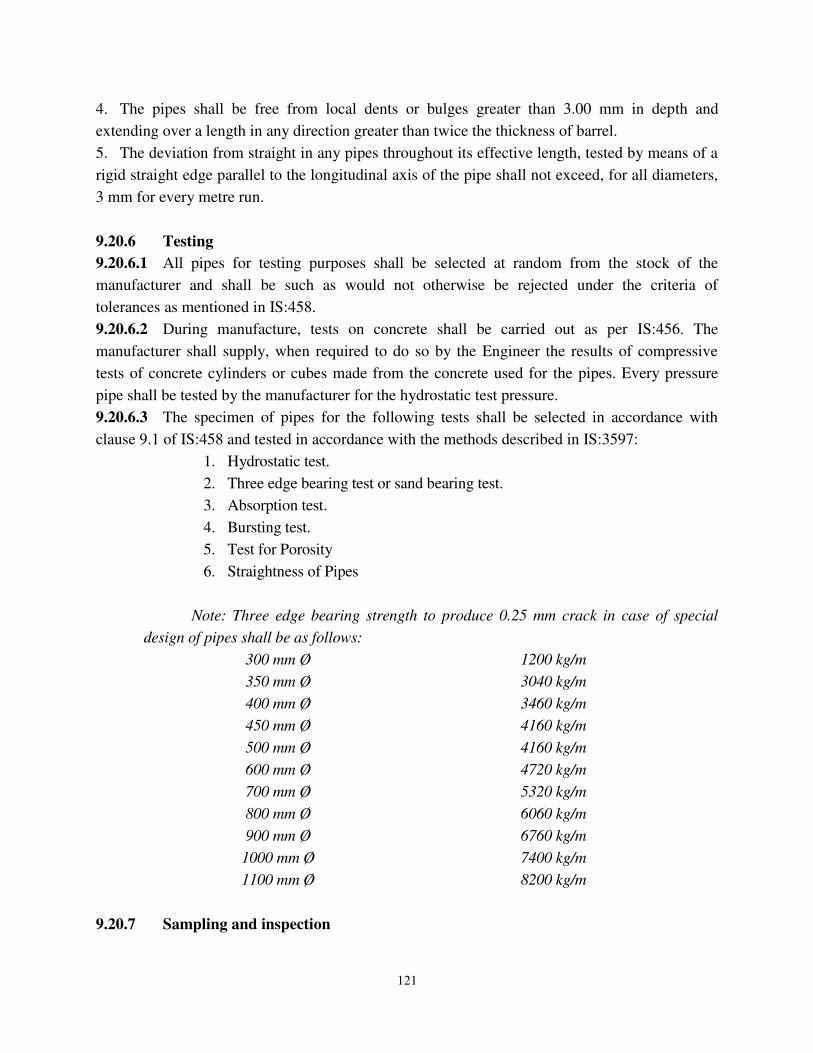
121
4. The pipes shall be free from local dents or bulges greater than 3.00 mm in depth and
extending over a length in any direction greater than twice the thickness of barrel.
5. The deviation from straight in any pipes throughout its effective length, tested by means of a
rigid straight edge parallel to the longitudinal axis of the pipe shall not exceed, for all diameters,
3 mm for every metre run.
9.20.6 Testing
9.20.6.1 All pipes for testing purposes shall be selected at random from the stock of the
manufacturer and shall be such as would not otherwise be rejected under the criteria of
tolerances as mentioned in IS:458.
9.20.6.2 During manufacture, tests on concrete shall be carried out as per IS:456. The
manufacturer shall supply, when required to do so by the Engineer the results of compressive
tests of concrete cylinders or cubes made from the concrete used for the pipes. Every pressure
pipe shall be tested by the manufacturer for the hydrostatic test pressure.
9.20.6.3 The specimen of pipes for the following tests shall be selected in accordance with
clause 9.1 of IS:458 and tested in accordance with the methods described in IS:3597:
1. Hydrostatic test.
2. Three edge bearing test or sand bearing test.
3. Absorption test.
4. Bursting test.
5. Test for Porosity
6. Straightness of Pipes
Note: Three edge bearing strength to produce 0.25 mm crack in case of special
design of pipes shall be as follows:
300 mm Ø 1200 kg/m
350 mm Ø 3040 kg/m
400 mm Ø 3460 kg/m
450 mm Ø 4160 kg/m
500 mm Ø 4160 kg/m
600 mm Ø 4720 kg/m
700 mm Ø 5320 kg/m
800 mm Ø 6060 kg/m
900 mm Ø 6760 kg/m
1000 mm Ø 7400 kg/m
1100 mm Ø 8200 kg/m
9.20.7 Sampling and inspection
122
9.20.7.1 In any consignment, all the pipes of same class and size and manufactured under
similar conditions of production shall be grouped together to constitute a lot. The
conformity of a lot to the requirements of this Specification shall be ascertained on the
basis of tests on pipes selected from it.
9.20.7.2 The number of pipes to be selected from the lot shall be in accordance with column
with column 1 and 2 of Table 9 of IS:458.
9.20.7.3 Pipes shall be selected at random in order to ensure randomness, all the pipes in the lot
may be arranged in a serial order and starting from any pipe, every “r th” pipe be selected till the
requisite number is obtained, “r” being the integral part of N/n where “N” is the lot size and “n”
is the sample size.
9.20.7.4 All the pipes selected as per Clause 15.1.7.3 shall be inspected for dimensional
requirements, finish and deviation from straight.
9.20.7.5 The number of pipes to be tested for tests under Clause 15.1.6.3 shall be in
accordance with column of Table 9 of IS:458. These pipes shall be selected from pipes that have
satisfied the requirements mentioned in Clause 15.1.7.4
9.20.7.6 A lot shall be considered as conforming to the requirements of IS:458 if the following
conditions are satisfied.
1. The number of defective pipes (those not satisfying one or more of the requirements for
dimensions, finish and deviation from straight) shall not be more than the permissible number
given in Column 3 of Table 9 of IS:458.
2. All the pipes tested for various tests as per Clause 15.1.6.3 shall satisfy corresponding
requirements of the tests.
3. In case the number of pipes not satisfying requirements of any one or more tests, one or two
further sample of same size shall be selected and tested for the test or tests in which failure has
occurred. All these pipes shall satisfy the corresponding requirements of the test.
9.20.8 Marking
9.20.8.1 The following information shall be clearly marked on each pipe: 1. Internal diameter of pipe.
2. Class of pipe.
3. Date of manufacture, and
4. Name of manufacturer or his registered trademark or both
5. ULB Name - NKUSIP.
9.20.9 Laying
9.20.9.1 Laying of pipe shall conform to Clause 15.11. 9.20.10 Jointing

123
9.20.10.1 Jointing of RCC pipes shall be done as per the requirements of following
Specifications and as per the relevant IS. The type of joints shall be as specified in the Contract /
Drawing. After jointing extraneous material if any, shall be removed from the inside of the pipe
and newly made joints shall be thoroughly cured. In case, rubber sealing rings are used for
jointing, these shall conform to IS:5382.
9.20.10.2 Spigot and Socket Joint (Rigid)
The spigot of each pipe shall be slipped home well into the socket of the pipe
previously laid and adjusted in the correct position. The opening of the joint shall be filled with
stiff mixture of cement mortar in the proportion of 1:1, which shall be rammed with caulking
tool.
9.20.10.3 Collar Joint (Rigid)
After laying the RCC pipes at proper alignment and gradient their abutting faces
shall be coated with hot bitumen in liquid condition by means of a brush. The wedge-shaped
groove in the end of the pipe shall then be filled with a tarred gasket in one length for each joint.
The collar shall then be slipped over the end of the pipe and the next pipe butted well against the
tarred gasket by suitable appliances approved by the Engineer so as to thoroughly compress the
tarred gasket into the grooves, care being taken that the concentricity of the pipes and levels are not
disturbed during this operation. The collar shall then be placed symmetrically over the end of the
two pipes and the space between the inside of the collar and the outside of the pipe filled with a
mixture of cement and sand in the proportion of 1:1, tempered with just sufficient water to have a
consistency of the semi dry conditions, well packed and thoroughly rammed with caulking tools.
The joints shall be finished off with a filled sloping at 45o to the side of the pipe. The finished
joints shall be protected and cured thoroughly as directed by the Engineer. Any plastic solution or
cement mortar that may have been squeezed into the inside of the pipe shall be removed so as to
leave the inside of the pipe perfectly clean.
9.20.10.4 Spigot and Socket Joint (Semi-flexible)
This joint is composed of specially shaped spigot and socket ends on the RCC pipes. A
rubber ring, shall be lubricated and then placed on the spigot which is forced into the socket of the
pipe previously laid. This compresses the rubber ring as it rolls into the annular space formed
between the two surfaces of the spigot and socket, stiff mixture of cement and mortar in the
proportion of 1:1, shall then be filled into the remaining annular space and rammed with a caulking
tool.
9.20.10.5 Collar Joint (Semi-flexible)
This joint is made up of a loose collar which covers two specially shaped pipe ends. Each
end shall be fitted with a rubber ring, which when compressed between the spigot and collar, seal
the joint. Stiff mixture of cement mortar in the proportion of 1:1, shall then be filled into the
remaining annular space and rammed with a caulking tool.
9.20.10.6 Spigot and Socket Joint (Flexible)
The RCC pipe with the rubber ring accurately positioned on the spigot shall be pushed well
home into the socket of the previously laid pipes. The manufacturers instructions shall be used, and

124
the manufacturers instructions shall be deemed to form a part of this Specifications. The rubber
rings shall be lubricated before making the joint and the lubricant shall be soft soap water or an
approved lubricant supplied by the manufacturer.
9.20.10.7 Flush Joint (Internal)
This joint shall be generally used for culvert pipe of 60 cm. diameter and over. The ends of
the pipes are specially shaped to form a self-centering joint with an internal jointing spaces 1.3 cm
wide. The finished joint is flush with both inside and outside with the pipe wall. The jointing space
is filled with cement mortar in the proportion of 1:1, mixed sufficiently dry to remain in position
when forced with a trowel or rammer.
9.20.10.8 Flush Joint (External)
This joint is suitable for pipes which are too small for jointing from inside. This joint is
composed of specially shaped pipe ends. Each end shall be butted against the other and adjusted in
correct position. The jointing space shall then be filled with cement mortar in the proportion of 1:1,
sufficiently dried and finished off flush. Great care shall be taken to ensure that the projecting ends
are not damaged as no repairs can be readily effected from inside the pipe.
9.20.10.9 Cleaning of pipes
As soon as a stretch of RCC pipes has been laid complete from manhole to manhole or for a
stretch as directed by the Engineer, The Contractor shall run through the pipes both backwards
and forwards a double disc or solid or closed cylinder 75 mm less in diameter than the internal
diameter of pipes. The open end of an incomplete stretch of pipe line shall be securely closed as
may be directed by Engineer to prevent entry of mud or slit etc.
9.20.10.10 If as a result of the removal of any obstruction, The Engineer considers that
damages may have been caused to the pipe lines, he shall be entitled to order the stretch to be
tested immediately. should such test prove unsatisfactory the Contractor shall amend the work
and carry out such further tests as are required by the Engineer.
9.20.10.11 It shall also be ascertained by Contractor that each stretch from manhole to
manhole or the stretch as directed by Engineer is absolutely clear and without any obstruction by
means of visual examination of the interior of the pipeline suitably enlightened by projected
sunlight or otherwise.
9.20.11 Testing at work site
9.20.11.1 After laying and jointing of RCC pipes is completed the pipe line shall be tested
as per IS, at work site following the Specifications and as directed by the Engineer. All
equipment for testing at work site shall be supplied and erected by the Contractor and shall be
rectified by him / her to the full satisfaction of the Engineer. The pipeline shall be thoroughly
disinfected and tested. Water used for test shall be of potable quality after test the water shall not
be released to the excavated trenches.
9.20.11.2 After the joints have thoroughly set and have been checked by the Engineer
and before backfilling the trenches, the entire section of the sewer (or storm water drain) shall be
proved by the Contractor to be water tight by filling in pipes with water to the level of 1.50 m.
125
above the top of the highest pipe in the stretch and heading the water up for the period of one
hour. The apparatus used for the purpose of testing shall be approved by the Engineer. The
Contractor if required by the Engineer shall dewater the excavated pit and keep it dry during the
period of testing. The loss of water over a period of 30 minutes should be measured by adding
water from a measuring vessel at regular 10 minutes intervals and noting the quantity required to
maintain the original water level. For the approval of this test the average quantity added should
not exceed 1 litre / hour / 100 linear metres / 10 mm for nominal internal diameter. Any leakage
including excessive sweating which causes a drop in the test water level will be visible and the
defective part of the work should be removed and made good.
9.20.11.3 In case of pressure pipeline the completed stretch of pipeline shall be tested for
1.5 times the site test pressure. The site test pressure should not be less than the maximum
operating pressure plus the calculated surge pressure, but in no case should it exceed the
hydrostatic test pressure, as specified in IS:458
9.20.12 Measurement
All RCC pipes shall be measured according to the work actually done and no allowance will be
made for any waste in cutting to the exact length required. The measurement for pipes shall be in
running metres nearest to a cm. of length along the centre line of pipe as actually laid at work
sites and not based on the actual number of pipes laid at site.
9.20.13 Rate
9.20.13.1 The rate for providing, laying and jointing of RCC pipes shall be deemed to include
the cost of collars / rubber rings, jointing material, testing and the extra excavation required for
ordinary bedding of pipes and also for collars and pipe sockets if any.
9.20.14 Notes
9.20.14.1 If any damage is caused to the pipeline during the execution of work or while cleaning / testing the pipeline as specified, The Contractor shall be held responsible for the same and shall replace the damaged pipeline and retest the same at his own cost to the full satisfaction of Engineer. 9.20.14.2 Water for testing of pipeline shall be arranged by the Contractor at his own cost.
9.20.15Manholes And Vent Shafts 9.20.15.1 SCOPE
9.20.16 This Specification covers the requirements for providing and construction of ancillary
works such as manholes, scraper manholes, vent shafts, etc.
9.20.17 APPLICABLE CODES
9.20.18 The following standards, unless otherwise specified herein, shall be referred. In
all cases, the latest revision of the Codes shall be referred to. If requirements of this Specification
conflict with the requirements of the Codes and standards, this Specification shall govern.
IS:111 Code of Practice for Ancillary Structures (Part I) - Manholes.
IS:555 Cast Iron Steps for Manhole.
126
IS:1077 Common Burnt Clay Building Bricks
IS:3102 Classification of Burnt Clay Bricks.
IS:395 Method of Sampling and Testing Clay Building Bricks.
IS:2212 Code of Practice for Brick Work.
9.20.19 MANHOLES
9.20.20 Location
9.20.20.1 Manholes shall be constructed at places as shown on Layout Plan Drawings and as
directed by the Engineer.
9.20.21 Excavation
9.20.21.1 Excavation shall be done in accordance with Chapter 3 of this Specification.. The
rate quoted for manhole shall be inclusive of excavation and backfilling, bailing or pumping out
water and shoring.
9.20.22 Benching in Manholes
The manhole benching shall be constructed of M15 concrete. The bottom part of manhole
including the benching can be cast in situ or precast and positioned at site.
The benching shall be shaped according to the number of pipes entering and the pipe leaving the
manhole. In general the slope of the benching shall be 1:6. the minimum height of benching
above the pipe shall be 50mm. Benching of channel is to be 0.8D ( D-diametre of the pipe)
9.20.23 VENT SHAFTS
9.20.24 General
Vent shafts shall be erected at places shown on the Drawings of longitudinal sections of the
sewers or as directed by Engineer.
9.20.25 RCC Vent Shafts
RCC vent shaft shall be of 100 mm Ø and 6.0 m height from ground level with inside core 150 X
150 at top & 200 X 200 at bottom in PCC M150 foundation including flue chamber in brick
masonry CM 1:4 with 20 mm thick cement plastering CM 1:3. This shall be connected to the
nearest manhole shaft by 150 mm diameter GSW pipe or as directed by the Engineer.
9.20.26 Jointing of Pipes
The spigot and socket joints of stoneware pipes shall be of rigid type and shall be caulked with
tarred gasket (prepared ready for use before being brought on the work in one length for each
joint and sufficiently long to entirely surround the spigot end of the pipe. The gasket shall be
driven, as far as possible, by means of suitable instruments. After the pipes are \thoroughly
cleaned and moistened, a mixture of one part of cement and one part of clean fine sand tempered
with just sufficient water to have a consistency of semi-dry condition shall be forced into the
joint and well rammed with caulking tools, so that the whole space around the spigot and socket

127
is completely filled with lightly chalked mortar and the joints shall be finished off with a splayed
fillet sloping at 5 degrees to the side of the pipe.
9.20.27 Measurement for Vent Shaft
The rate quoted in Schedule of Quantities and Rates for Vent shaft shall be deemed to include
the cost of RCC vent shaft, necessary excavation to manhole inclusive of concrete encasement,
erecting, etc. complete. The measurement for vent shaft shall be on per number basis.
9.20.28 EQUIVALENCY OF STANDARDS AND CODES
Wherever reference is made in the Contract to specific standards and codes to be met by the goods
and materials to be furnished, and work performed or tested, the provisions of the current edition or
revision of the relevant standards and codes in effect shall apply, unless otherwise stated in the
Contract. Where such standards and codes are national, or relate to a particular country or region,
other authoritative standards which ensure an equal or higher quality than the standards and codes
specified will be acceptable subject to the Engineer's prior review and written approval. Differences
between the standards specified and the proposed alternative standards must be fully described in
writing by the Contractor and submitted to the Engineer at least 28 days prior to the date when the
Contractor desires the Engineer's approval. In the event the Engineer determines that such proposed
deviations do not ensure equal or higher quality, the Contractor shall comply with the standards
specified in the documents, samples and Tests. The Contractor shall be responsible to develop a
quality assurance program and to provide all necessary materials, apparatus, instruments,
equipment, facilities and qualified staff for sampling, testing and quality assurance of the materials
and the works under the Contract. Without limiting the generality of the foregoing, the Contractor
shall either (i) establish a testing laboratory at the site of Works which is adequately equipped and
staffed to carry out all sampling and testing in accordance with the requirement set out in this
Standard Specifications and/or Special Specifications and provide all field equipment and apparatus
as necessary to conduct all specified in-situ tests and/or any Tests on Completion, or (ii) arrange for
routine sampling, testing and reporting, as required, through a certified independent testing
laboratory acceptable to the Engineer. The Contractor shall obtain the approval of the Engineer for
the quality control programme developed by him and incorporate any modifications suggested by
the Engineer at no extra cost. All costs of such sampling, testing and reporting of test results will be
borne by the Contractor, and the Contractor shall include sufficient provisions in his tendered rates
to allow for independent sampling and laboratory testing under the direction of the Engineer up to
5% of the total number of required tests (subject to a minimum of 2) at no additional cost. The
Contractor shall furnish certified copies of all test reports to the Engineer within 3 days of
completion of the specified tests. The Contractor shall, within 14 days after the date of the Letter of
Acceptance, submit to the Engineer for his consent a detailed description of quality assurance plan
and the arrangements for conducting the quality assurance plan during execution of the Works,
including details of his testing laboratory, equipment, staff and general procedures. If following
submission, or at any time during the progress of Works, it appears to the Engineer that the
128
Contractor's quality assurance plan is not adequate to ensure the quality of the Works, the
Contractor shall produce a revised plan as desired by the Engineer, which will be adequate to ensure
satisfactory quality control.
Protection of Utilities
The Contractor is required to carefully examine the location of the Works and their alignments and
to make specific enquiries and co-ordinate with all departments /authorities concerning all utility
lines such as water pipes, sewers, gas pipe, telephone (underground and/or overhead) lines, optic
fibre cables, electric and telecommunication cables (underground and/or overhead) lines, any other
utility lines etc; and to determine and verify to his own satisfaction the nature, sizes, position, depth
and lengths of such utilities from authentic records. The Contractor shall be wholly responsible for
the protection and/or relocation of such utilities as may be required, and shall not make any claim
for extra work or extra time that may be required to protect or facilitate relocating such utilities. Any
damage to the Utilities caused by the Contractor shall be restored/ repaired at the cost of Contractor.
In case the alignment of the pipeline crosses the high tension electrical transmission lines
belonging to the KPTCL / HESCOM or other authorities/ departments, the Contractor shall take
all precautions necessary to see that the work is carried out with care and safety, without
disturbing such transmission lines. The Contractor will be responsible to carry out all
construction activities in such reaches in consultation with the owners of such facilities.
However, satisfactory completion of the entire work will be the responsibility of the Contractor.
Tests during Construction
For ensuring the requisite quality of construction, the Materials and Works shall be subject to the
quality control tests as described in this Standard Specifications and Quality Control Manual as
applicable and as directed by the Engineer. The testing frequencies set forth are desirable minimum
and the Engineer shall have full authority to get the additional tests carried out by the Contractor as
frequently as he may deem necessary, to satisfy himself that the Materials and Works comply with
the appropriate Specifications. Third party inspection shall be arranged as and when required by the
Engineer for the tests.
Where no specific testing procedure is mentioned, the tests shall be carried out as per the prevalent
accepted Engineering practice to the directions of the Engineer.
9.20.29 PIPE LAYING
Earth work Excavation for pipe trenches in all classifications of soil including hard rock by control
blasting/ chiselling shall be done as directed by the Engineer including clearing and grubbing along
the alignment including uprooting rank vegetation, grass, bushes, shrubs, saplings and trees of girth
up to 300mm, in areas of light / thorny jungle, removal of stumps disposal of unserviceable
materials including burning vegetation as directed by the Engineer, stacking of serviceable materials
with all lead and lift, labour charges cutting road surfaces of all types and depositing the excavated
earth on bank up to lead of 50m providing danger lights and use of sight rails and boning rods
129
wherever necessary, shoring and strutting, wherever required, excavation in watery situation or foul
conditions, dewatering for over night recuperation with any approved suitable method of
dewatering to keep the trench dry till the completion of the works.
All the sewer pipes, specials & valves, shall be priced at the rate inclusive of all taxes,
transportation charges, insurance, railway freight, unloading from railway wagons, loading into
trucks, transportation to stores or sites, unloading, stacking etc., complete, rolling and lowering into
trenches, laying true to line and level and perfect jointing including caulking with hemp dipped in
tar and jointing with CM 1:1.5 or rubber ring, gaskets and testing as per IS, curing for 10 days
including cost of jointing materials
Gravel, cement concrete bedding and concrete encasing for the pipelines shall be provided,
wherever required.
Backfilling the pipeline trenches shall be with selected available earth obtained from the trench
excavation or from approved new earth brought from outside with all lead and lifts, including
watering and consolidation in layers of 150mm thick to the desired density and disposing of the
surplus earth as per drawings, specifications and as directed by the Engineer for laying pipes/ joints
of various depths for the different diameter and materials of pipes.
MANUFACTURE, SUPPLYING, LAYING, JOINTING AND TESTING OF PIPES
Manufacturing, supplying, laying, jointing, testing and commissioning of pipes used for Sewerage
shall generally conform to Section 15 of Standard Specification document and construction of
manholes shall conform to Section 16 of Standard Specifications. Any additions and / or
modifications specified in this Section shall also be followed. The alignment of sewer lines given
in the Drawings has to be verified at site by the Contractor. The alignment of sewers shall be
along side , centre or across the carriageway. In case, if in some stretches it runs along the storm
water drains then in these stretches, the top of the manholes shall be raised above the high flood
level of the drains as per the details given in the construction drawings. Pipes shall be laid
underground with a minimum earth cover of 1m above the crown of the pipe, unless otherwise
specified. All pipes, fittings and material shall be inspected and approved by the Engineer before
being laid. Any pipes, fittings or material placed before those are inspected and approved shall
be removed and replaced with approved material. Before laying the pipes, necessary bedding
shall be provided for the pipes, if specified.
In general, unless and otherwise specified, the sewer lines shall be of SWG pipes and RCC NP3
pipes. The branch sewer, crossing the storm water drains and roads, as indicated in Drawings,
shall be of RCC NP3 pipe encased in NP4 pipes. The specifications of manufacturing, testing,
transporting to site, laying jointing etc of pipes are explained under chapter.
9.20.30 EARTHWORK IN EXCAVATION FOR PIPELINE TRENCH
General
The Contractor shall make all excavations required for laying and jointing of the pipeline and
construction of pertinent structures as required by the project. Except where otherwise required
by the project or instructed by the Engineer, all excavation shall be in open cut or with shoring &

130
strutting to the specified widths and depths. The Contractor is deemed to have quoted the rates
accordingly with regard to the likely conditions that may be met with during the execution of the
works, with regard to the underground obstructions or conditions, necessary dewatering
requirements including well point system or other means of dewatering the trenches before,
during and after excavation, laying of bedding material, laying and jointing sewers, hydraulic
testing and backfilling, construction of manholes, pipe supports etc., in sub terrain under ground
water, rain water, sullage and waste water etc.,
Earth work excavation for pipeline trenches and manholes include clearing vegetation, shoring,
strutting, dewatering to keep the trench in dry condition and disposing the excess earth excavated
material as approved by the Engineer, depositing on bank up to final lead providing danger lighting
and using sight rails and boning rods at every 15 m or between manholes which ever is less,
wherever necessary as directed, in all types of soil including hard rock. A minimum of three sight
rails are to be maintained at all times during pipe laying between manholes. The rate quoted for
excavation shall include all the above mentioned activities unless separately measured in the Bill of
quantities.
Dewatering
The Contractor shall be responsible for the adequate pumping, drainage and bailing out of water
from the excavation. Dewatering shall be either continuous or intermittent using diesel pump or any
other method approved by the Engineer. The method of dewatering shall depend on site condition
and should be furnished by the Contractor and approved by the Engineer. The method of dewatering
shall be either sump pumping or well point system. The effectiveness of each method will depend
upon the nature of the soil, the proportions of the trench and degree of lowering required. Pumping
test may be necessary to determine which method is suitable. If sump pumping is not practicable,
then other control methods shall be considered and got approved by the Engineer. The trenches
shall be kept dry till the completion of work, which includes excavation, pipeline laying, jointing,
testing and commissioning and backfilling. Precaution shall be taken against the flotation of the
pipes. The Contractor shall conduct ground studies if found necessary and the cost for such studies
shall be borne by the Contractor himself. The Contractor shall be responsible for the adequate
pumping, drainage and bailing out of water met due to all causes from the excavation for laying
sewer lines, construction of manholes, wet wells and all types of other constructions. In case of
failure to make such provisions or any other provisions, which may result in unsuitable sub-grade
conditions, the Contractor shall replace and repair the sub-grade as directed to the satisfaction of the
Engineer, at his own cost and responsibility. Should the Contractor select to use a gravel sub-grade
with or without pipes to facilitate flow of water to pumps or other points of disposal, such gravel
sub grade or conveying pipes shall not be measured or paid as an extra item..The dewatering shall
be done by resorting to the following or any other method approved by the Engineer
Sump pumping
This method shall be used in highly or moderately permeable soils such as gravel, sand or sand
gravel mixtures. This method is simple and cheap to install and used with watertight trench
131
sheeting to limit the volume of flow. To prevent the boiling in the bottom of the trench the
following precautions shall be taken
Drive sheeting deeper to lengthen drainage path
Use open pipe surrounded in gravel as a sump
Move the sump to one side of the trench
To prevent removal of fines from soil causing loss of strength in the soil and undermining of the
trench bottom and side support, the following precautions shall be taken:
Surround suction inlet with protected graded filter
Increase flow rate through the soil by using open pipe surrounded with gravel.
The delivery side of the pump shall be monitored by taking samples of water and checking the
proportion of fines being removed. If fines are being continuously withdrawn or there are signs of
trench instability, sump pumping shall be stopped and alternative methods considered.
Well point system
In this method, well points are installed at regular intervals on one or both sides of the trench and
linked parallel to a header main connected to a pump. Well points are usually installed at 0.6 to
2.0m centre to centre by jetting them in. In ground with dense layers or cobbles & boulders, it may
be necessary to pre bore the layers. The efficiency of the well points is increased by sanding in the
well point and riser using a column of sharp sand. This method has an advantage of drawing water
away from the trench and in suitable conditions is effective in lowering the water by 4 to 6m. It will
also reduce the hydrostatic heads on the trench support system. Its greatest use is in sand. The
heavy flow in permeable ground, such as gravel, demand the well points to be so close together that
the method becomes not practical. In clays, the rate of seepage is too small for the system to be
properly effective. Silts can be stabilized in certain conditions by using special procedures. The
well pointing shall be either single sided well point or double sided well point. For higher depths
double sided well point with multi stage shall be considered. Should the Contractor select to use a
gravel sub-grade to facilitate flow of water to pumps or other points of disposal, such gravel sub-
grade shall not be measured or paid for as an extra item. The contractor shall assess the availability
of extra earth required for refilling in case of shortage in any particular reach well before quoting
rates. In case the Contractor resorts to mechanical excavation, the Contractor shall take care of
proper refilling, consolidation and disposal of surplus earth. Disposal of ground water is to be away
from the area of influence of the pipe laying. Suitable temporary pipelines shall be laid to existing
watercourses. For lowering the sub soil water level for the construction of wet wells the bores have
to be installed/jetted at a spacing between two bores varying from 0.6 to 1.0m depending upon sub
strata and the incoming flow of water. The bore should be installed at least 1.0m away from the
periphery of the excavated earth. The dewatering includes removal of ground water, springs,
seepage water, sullage, sewage, running water, rain water etc., in order to make the trench dry for
sewers, pits for manhole and for construction of wet well etc.
132
Payment for Dewatering
Dewatering shall be paid based on the volume of water pumped out as measured at site. The
Contractor has to provide a suitable water meter on the delivery main for measuring the water
pumped out.
9.20.31 Excavation for Manholes and Other Appurtenant Structures
The Contractor shall excavate as required for all the structures with foundations to firm, undisturbed
earth up to the level of the underside of the structure. If the excavation is in rock, the Contractor
shall excavate all rock at least to the minimum limits shown on the standard details for trenches and
to the grade of the bottom of manholes and other structures as required. Where the bottom of the
structure is in rock, it shall be ensured that no rock shall project above the lower surface of the
concrete in such a manner so as to reduce the required thickness of concrete placed simultaneously
as an integral part of the foundation and to the outside of structure foundation where structure is to
be built. The Contractor shall excavate the trench / pit to provide necessary working space on all
sides and for accommodating any sheathing, shoring or bracing etc.
9.20.32 BEDDING FOR THE PIPE
Bedding shall be provided all along the stretch of the pipeline, which differs based on the area
through which the pipeline passes. Pipe shall be laid on specified bedding. When rock ,very loose
soil,clay, black cotton soil etc are met with along the alignment, the pipe shall be provided with
gravel bedding. Where the pipeline crosses the road below it, and the pipe may be subjected to
damage from passing vehicles, concrete arch bedding shall be used in such situations. However, the
type of bedding to be provided shall be as decided by the Engineer. The various types of bedding
are Earth Bedding, Gravel Bedding, Concrete Arch/ Cradle Bedding and Special Bedding in poor
sub grades.
Earth Bedding
The excavation shall be carried out to 150 mm below the pipes and backfilled with compacted
earth as shown in drawing. Filling and removing earth or similar materials beneath the allowable
depth as above to adjust with the grade will not be permitted except filling with compacted
granular bedding material or mooru
Gravel Bedding
Wherever rock is met with, it shall be removed up to minimum 150 mm below the bottom level of
the pipe to a minimum width equal to the width of the trench and the resulting space shall be filled
up with good quality compacted gravel. The granular material shall be filled in the trench up to the
level of ¼ the outer diameter of the pipeline, above the bottom of trench and well compacted.
Unless otherwise directed by the Engineer, rock excavation shall progress at least 20 m in advance
of the pipe length proposed to be laid. Graded granular bed material shall be used in Class B
bedding and the surround shall consist of durable gravel, crushed stone or disintegrated rock. Any
imported bed and surround materials shall be to the approval of the Engineer and shall be supplied
with certification, which gives details of its content, source and grading. In all cases the soluble
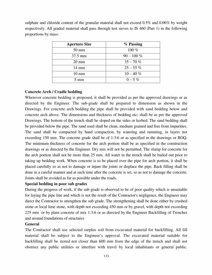
133
sulphate and chloride content of the granular material shall not exceed 0.5% and 0.06% by weight
respectively. All graded material shall pass through test sieves to IS 460 (Part 1) in the following
proportions by mass:
Concrete Arch / Cradle bedding
Wherever concrete bedding is proposed, it shall be provided as per the approved drawings or as
directed by the Engineer. The sub-grade shall be prepared to dimension as shown in the
Drawings. For concrete arch bedding the pipe shall be provided with sand bedding below and
concrete arch above. The dimensions and thickness of bedding etc; shall be as per the approved
Drawings. The bottom of the trench shall be sloped on the sides or kerbed. The sand bedding shall
be provided below the pipe. The sand used shall be clean, medium grained and free from impurities.
The sand shall be compacted by hand compaction, by watering and ramming, in layers not
exceeding 150 mm. The concrete grade shall be of 1:3:6 or as specified in the drawings or BOQ.
The minimum thickness of concrete for the arch portion shall be as specified in the construction
drawings or as directed by the Engineer. Dry mix will not be permitted. The slump for concrete for
the arch portion shall not be more than 25 mm. All water in the trench shall be bailed out prior to
taking up bedding work. When concrete is to be placed over the pipe for arch portion, it shall be
placed carefully so as not to damage or injure the joints or displace the pipe. Back filling shall be
done in a careful manner and at such time after the concrete is set, so as not to damage the concrete.
Joints shall be avoided as far as possible under the roads.
Special bedding in poor sub grades
During the progress of work, if the sub grade is observed to be of poor quality which is unsuitable
for laying the pipe line and which is not the result of the Contractor's negligence, the Engineer may
direct the Contractor to strengthen the sub grade. The strengthening shall be done either by crushed
stone or local lime stone, with depth not exceeding 450 mm or by gravel, with depth not exceeding
225 mm or by plain concrete of mix 1:3:6 or as directed by the Engineer Backfilling of Trenches
and around foundations of structures
General
The Contractor shall use selected surplus soil from excavated material for backfilling. All fill
material shall be subject to the Engineer’s approval. The excavated material suitable for
backfilling shall be stored not closer than 600 mm from the edge of the trench and shall not
obstruct any public utilities or interfere with travel by local inhabitants or general public.
Aperture Size % Passing
50 mm 100 %
37.5 mm 90 – 100 %
20 mm 35 – 70 %
14 mm 25 – 55 %
10 mm 10 – 40 %
5 mm 0 – 5 %

134
Handling and storage of excavated material must meet with the regulations of the Local
Government Authorities. The detailed specification for backfilling shall be as per Clause 8 of IS:
3114-1994.
9.20.33 Method of Backfilling
Trenches and excavated pits for structures shall be backfilled to original ground level or to such
other levels, as the Engineer may direct. All backfilling shall be carried out in orderly manner
expeditiously and consistent with good workmanship. Mechanical vibrators shall be used for
compaction of the trenches filled with back fill material wherever necessary.Backfill material put
into the trenches/pits for backfilling, shall unless otherwise specified be compacted and built up so
as to minimize future settlement as much as reasonably possible. For this, care shall be exercised in
selecting backfill material free from large hard clay lumps, especially in cramped areas directly
adjoining the walls of structures. Backfilling in trenches shall be done as pipe laying progresses,
with the permission of the Engineer, after the pipe or conduit is properly bedded, jointed and
inspected and all measurements for the location of Junctions are properly recorded by the Engineer
and sufficient time is allowed for the joint materials or cement concrete or mortar to set. However
the joints shall be left open for inspection during testing, which shall be backfilled after successful
completion of testing, after obtaining permission from the Engineer. Backfilling around and over the
pipe, conduit, or structure shall be taken up uniformly on all sides and in the sequence and manner
specified hereinafter, with care to avoid the displacement or damage to the pipe, conduit or
structure. Trenches and pits shall be carefully guarded till backfilling. For the purpose of
backfilling, the depth of trench shall be divided into the following three zones measured from
bottom to top of trench. The first zone shall be from bottom of trench to the centre line of pipe, the
second zone shall be from the level of centre line of pipe to a level of 300 mm above the top of pipe,
and the final zone shall be from a level of 300 mm above the top of pipe to the top of trench.
Backfilling in the trenches and around structures shall be carried out in horizontal layers of uniform
thickness of not more than 150 mm when measured loose. As may be necessary to attain maximum
compaction, the backfill material shall be moistened by sprinkling with water. After placing each
layer of backfill material, the layer shall be thoroughly and uniformly compacted by means of
mechanical or hand tampers. The compacting equipment and the manner of its use shall be subject
to the approval of the Engineer. After the backfill material is placed in the first two zones as
specified above, the remaining portion of the trench shall be machine backfilled. Even in this case
the backfill material shall be placed in uniform horizontal layers of not more than 150 mm
thickness. Small pebbles of size less than 50 mm, if any, shall be so distributed throughout the mass,
that all interstices are solidly filled with fine material. The backfill material shall be tamped with
mechanical tamping equipment like plate vibrator, after moistening the backfill by sprinkling with
water to obtain maximum compaction. Machine backfill shall be so conducted that the material is
not pushed down into the trench from above. Care shall be taken to place the material carefully
above the pipe irrespective of the method used for placing the backfill material. Throwing or
allowing material to fall from the edge of excavation may result in damage to the pipe joints or

135
alignment. If the trench is subjected to conditions, which might cause flotation of the pipe before
sufficient backfill has been placed; the Contractor shall take the necessary precautions to prevent
floatation of the pipe, conduit or structure. Before final acceptance of the work, additional tamped
earth shall be added to restore the settled trench surface to the required level of the adjacent earth
surface or to the base of crushed rock wearing surface or to the finished earth base. If from the
excavated soil, enough backfill material is not available, imported, selected and approved backfill
material from the borrow pits is required to be placed for backfill, on approval of the Engineer.
Backfilling of trenches where the excavation is in the rock shall be with the surplus soft soil located
within 200m from the site of work. If the soil is to be obtained from borrow pits the availability of
earth for this purpose, lead and lift etc shall be deemed to be verified by the Contractor while
quoting the rates.
9.20.34 COMPACTION TEST
The Contractor shall carry out tests for density of backfill at his own cost and that if the backfill
is found to be unsatisfactory, it shall be rectified or the backfilling shall be got done by the
Engineer through other agencies at the cost of the Contractor.
9.20.35 DISPOSAL OF SURPLUS EXCAVATED MATERIAL
The excavated material, which is in surplus to the requirements after backfilling shall be
removed/disposed off as directed by the Engineer with all lead and lift from the site. The disposal
site is to be assessed by the Contractor and got approved by the Engineer. No surplus or excess
material shall be disposed off in a stream / channel nor in any place where the pre-construction
surface drainage may have to be provided, without written permission of the Engineer.
9.20.36 METHOD STATEMENT
The method of operation, length of sewer to be excavated, method of barricading, property
access, dewatering, shoring, pipe laying, backfilling and road reinstatement shall be stated in a
‘Method Statement’ to be submitted at least 4 weeks before work is scheduled to commence in a
particular location. The written agreement of the Engineer shall be obtained to the method
statement. If any additional safeguards are required by the Engineer, these shall be incorporated
in the method statement at no extra.
9.20.37 Noise and Dust Control
The Contractor will ensure that the noise created by his activities is properly suppressed.
Adequate silencers fitted to construction machinery, particularly compressors and drills. Dust is
to be kept to a minimum by using water sprinklers. Utility service connections shall be
maintained to every property throughout the construction phase and thereafter. If any defect/
damage is caused it shall be repaired immediately and at the Contractor’s expense.
The disruption to the normal activities of residents and other members of the public is to be kept to
an absolute minimum. Extended working hours shall be permitted by the Engineer with the consent
136
of the local residents. No additional payment shall be made for any of these arrangements.
Adequate lighting shall be provided by the Contractor at his cost if night working is adopted.
9.20.38 WORKS INCLUDED IN EXCAVATION
The following works as per specifications are also included in excavation and the term
'Excavation' shall construe to mean all such items of work and the quoted rates shall include the
same:
Provision of side space or additional space in the trench / pit for working and / or
accommodating sheathing, shoring, bracing, etc.
Supply, installation and removal after the work, all-sheathing, shoring and bracing required to
protect the excavation where required or where such work is recommended by the Engineer.
Protection of excavations.
Providing adequate safety measures.
Additional work in connection with overhead wires and poles.
Excavations for socket and collar hollows.
Dewatering of trenches
Additional work in conducting blasting operations as required, in case the excavation is in rock.
Supplying and fixing of sight rails and boning rods in the trench to facilitate measurement of
work.
Temporary approaches to roads, properties etc., affected by excavation.
9.20.39 MEASUREMENT AND PAYMENT
Earthwork shall be measured based on the minimum width of trench specified and the depth as
approved in the working drawings. When trenches are taken in steps then 0.3m width shall be
allowed, for measurement purposes, for each step on either side of the trench, steps being taken
at 1.5m interval after the first 2m below ground level.
9.20.40 Pipeline works
The length of the sewer pipes shall be measured between the inner surfaces of consecutive
manholes at the invert level of the pipes along the central line of pipeline to the nearest centimetre.
The payment will be made per m length of pipe measured based on the quoted rates once the testing
and backfilling is done to the satisfaction of the Engineer. No part payment will be made for
excavation, pipes, laying and jointing etc unless otherwise specified.
9.20.41 For Bedding
For providing Earth, Gravel and Concrete arch bedding in accordance with Sub-Clauses 28.5.1,
28.5.2 28.5.3 and 28.5.4 respectively of this Section, the Contractor shall be paid at his tendered
rates under the relevant items for the quantities of bedding actually used based on the centre line
dimensions of the trench and considering the volume occupied by the pipe. For the extra cost of
137
over excavation in poor soils and strengthening the sub grade pursuant to Clause 28.5 of this
Section, the Contractor shall be paid extra.
9.20.42CONTRACTOR'S RESPONSIBILITY
9.20.42.1 Preparatory work
The contractor shall inspect the route along which the sewer line is proposed to be laid. He
should observe/ find out the existing underground utilities/ construction and propose suitable
alignment along which the sewer line is to be laid. He should make all efforts to keep the pipe as
straight as possible with the help of ranging rods. The alignment as proposed should be marked
on ground with a line of white chalk and got approved from Engineer. The Contractor shall
prepare L-Sections and strip plans along with this alignment showing the location of proposed
pipeline, existing underground utilities, existing electric poles and telephone poles, Monuments
and Ancient structures, drainage or culvert crossings, cross roads, land marks and any other
information available. The L-section and strip plans shall be got approved from the Engineer
before starting the excavation. The position of manholes, vent shafts etc, shall be shown on the
plan. The rates for earthwork excavation are deemed to include all these incidentals.
9.20.42.2 26.14.2 Alignment and the L-Sections
The alignments, L-section (depth of laying) and location of manholes, valves and chambers may
be changed at site in co-operation with and after approval of the Engineer. The minimum soil
cover to the top of the pipe crown shall be 1 m. The Contractor shall be responsible for the
adequate pumping, drainage and bailing out of water from the excavation. In case of failure to
make such provisions or any other provisions, which may result in unsuitable sub-grade
conditions, the Contractor shall replace and repair the sub-grade as directed to the satisfaction of
the Engineer, at his own cost and responsibility. Should the Contractor select to use a gravel sub-
grade to facilitate flow of water to pumps or other points of disposal, such gravel sub-grade shall
not be measured or paid for as an extra item.
9.21 ANCILLARY WORKS
The Contractor shall build Manholes, Vent shafts, Drop manholes, Valve Chambers, Thrust
Blocks, Anchor Blocks, Pipe Supports, Pipe Ducts, Pipe bedding and such other miscellaneous
structures that may be required at the locations shown by the Engineer and as shown in the
drawings or as may be otherwise specified or directed. The specifications of these ancillary
structures shall generally be as specified in unless in this Section or advised by the Engineer
based on the site conditions.
9.21.1 Manholes
Manholes shall be constructed at places as shown in the drawings or as directed by the Engineer
for which payment shall be made at quoted rates. Any manholes required to be provided extra,
138
at the locations shown by the Engineer, shall be provided by the Contractor, for which payment
shall be made extra at the quoted rates. The Contractor is responsible for giving suitable
connections at the junctions of sewer lines with the manholes. The manholes have been divided
into different categories based on depth. The depth of manhole shall be measured from the top of
cover to the invert level of the deepest outgoing sewer from the manhole. The minimum depth of
manhole shall be one metre. Above one metre and up to 1.5 metre, a single unit rate shall be quoted
by the Contractor at which he shall be paid, for any manhole of depth between 1.0 m and 1.5 m.
Similarly, for manhole depth from 1.5 meter to 2.0 meter, 2.0 m to 2.5 m and so on, the unit rate
shall be paid for all manholes within the specified depth range. The rate includes providing and
constructing of RCC Pre-cast manhole chambers in M25, conical in shape at top or as otherwise
specified, as per drawings and specifications, with 1:2:4 CC foundation using 20mm down grade
jelly of approved quality of thickness varying from 200 mm to 450 mm and with an offset /
projection all round the chamber varying from 200mm to 400 mm and the pre-cast conical parts and
cylindrical walls of Manhole chamber shall be with RCC M25 grade concrete for various depths as
per drawing. Providing, fabricating and fixing reinforcement TMT steel of all sizes including
cutting bending, tying, placing etc. Filling the joints of precast RCC manhole members with non-
shrink grout using CONBEXTRA GP-2 of FOSROC or equivalent compound , mixed with 6mm
down washed and dust free coarse aggregates (4parts of Conbextra GP-2 & 1 part of 6mm jelly by
weight ) as per manufacturers specification & as per drawings; Fixing of inlet & out let sewer pipe
lines and fixing of service connection pipes while precasting or making suitable provision for fixing
in site at necessary depths, including necessary number of tubes / pipes to be provided & fixed
while precasting the walls for pressure grouting are also included. Pressure grouting shall be done
with neat cement slurry mixed with CEBEX 100 of FOSROC or equivalent compound as per
manufacturers’ specification & as per direction of the Engineer. The work also includes (i)
Providing necessary number of lifting hooks for lifting and placing of precast members; (ii)
Providing benching in CC of grade M15 with 1:6 slope in the concrete towards the central drain,
finished smooth and fixing of pipes inside MH chamber in M15 grade CC with graded metal of
20mm and downsize, (iii) Supplying and fixing manhole frame and cover (SFRC of heavy duty
cover as directed) in 1:1.5:3cement concrete, (iv) Supplying and fixing of PVC encapsulated foot
steps using 12mm TMT steel(as per IS:10910) in case of casting into the pre cast rings or steps
welded to 12m thick MS plate also PVC encapsulated for bolting on to the precast rings, staggered
at 300mm apart as directed, payment for which shall be done separately, (v) Engraving manhole
number on the inner surfaces etc., as per drawing, (vi) Refilling in trench with selected available
earth from chamber/trench excavation including watering and consolidation in layers 150mm thick,
(vii) Stacking the useful material and disposing of the surplus earth / unsuitable material as directed,
(viii) Cost of, transportation erection , fixing of precast RCC manhole members for satisfactory
completion of the works, including necessary form work , labour, tools , plants, HOM of Machinery
and materials with all lead and lifts for various diameters and depths as per drawing, specifications,
(ix) Testing for water tightness of the manhole chamber shall be as per Clause 29 and as directed by
the Engineer. Equivalent compounds other than mentioned above shall be got approved from the

139
Engineer before commencement of works. Any manhole required to be provided extra, at the
locations shown by the Engineer, shall be provided by the Contractor, for which payment shall
be made extra, at the quoted rates. The Contractor is responsible for giving suitable connections
at the junctions of sewer lines with the manholes. Manholes shall be constructed with Cement
concrete grade of M25. They shall be circular in shape throughout the depth. The manholes shall
be fixed with heavy-duty circular fibre reinforced concrete manhole covers and frames of 560 mm
diameter conforming to IS 1726. The cement used for the construction of RCC works and finishing
works of manhole shall be of sulphate resistant cement only. No other cement will be allowed for
the construction of RCC manholes. The pipe specials shall be provided as per relevant IS
standards. The Cost of the Manholes for various depths as per the drawing furnished shall include
the cost of cement, sand, jelly and steel, manhole cover with frame, steps, bedding concrete,
haunching concrete, finishing/plastering, dewatering to keep the manhole dry until final testing,
transportation, erection, fixing, of precast RCC manhole member, including cost of all required
materials, labour, HOM of plant and machinery etc complete. Manholes shall be tested as per
relevant provisions in CPHEEO Manual.
9.21.2 Internal Drop Manholes
In a manhole, wherever the difference between the invert level of downstream sewer and
the invert level of the upstream sewer is greater than 60 cm, an internal drop pipe shall be
provided at that position. The locations of the drop manholes shall be provided in construction
drawings. The drop connection shall be provided as illustrated in the typical drawing. CI pipes as
specified in Bill of Quantities and specials conforming to IS: 1729 shall be used for providing the
drop in the manhole. They shall be of the same size as that of the connecting upstream sewer pipe.
For connecting the incoming sewer pipe, a CI tee with socket ends shall be extended through the
wall of the manhole. On one side of this tee, a CI pipe with both ends spigot shall be connected to
facilitate the drop in the manhole. This drop pipe should terminate at the lower end with a plain or
duck foot bend to discharge the flow at 45o or less to the direction of flow in the receiving sewer.
The benching concrete in the manhole should surround the joint of the terminating bend and a neat
channel shall be made in the benching concrete to direct the flow to the receiving sewer. The joint
between CI tee and the connecting GSW / RCC sewer line shall be made with cement mortar 1:1 (1
cement : 1 fine sand). The joints between CI pipes and fittings in the drop manhole shall be lead
caulked. The CI pipes shall be suitably supported with MS fasteners at 300 mm c/c. The holes made
in the walls of the manhole for connection purposes shall be made good with M15 Cement Concrete
and plastered with cement mortar 1:3 (1 cement: 3 coarse sand) on the inside of the manhole wall.
9.21.3 Rocker pipe
A rocker pipe of length not more than 600mm length, shall be provided where the sewer pipe
enters and exits the manhole and connected to the sewer main.
9.21.4 VENT SHAFTS
CI Vent shafts shall be erected at places as directed by the Engineer. Vent shaft shall be

140
constructed as per the drawing provided in the document for which payment shall be made at
quoted rates. Vent shaft shall be constructed as per Bill of Quantities and Drawings.
9.21.5 VALVE CHAMBERS, PIPE SUPPORTS,PIPE DUCTS,PIPE ENCASING etc.,
The Contractor shall build Pipe Supports, Pipe Ducts and such other miscellaneous structures that
may be required at the locations shown by the Engineer and as shown in the drawings or as may be
otherwise specified or directed. The specifications of these ancillary structures shall as per Bill of
Quantities, unless otherwise specified in this Section or advised by the Engineer based on the site
conditions. The various structures shall be built as the pipe laying progresses and the Engineer at his
discretion, may stop work entirely on the laying of pipe or construction of other structures, until the
construction of the structures already approved by the Engineer are completed by the Contractor.
9.21.6 PROTECTION TO PIPES
Wherever the depth of cover of pipe is less than 1.0 m, the pipeline shall be protected with
appropriate measures such as providing PCC guard stones, ducts, walkways to ensure that no traffic
passes over the pipeline.
9.21.7 THRUST BLOCKS AND ANCHOR BLOCKS
Thrust blocks shall be provided for both horizontal and vertical bends wherever required in the
pipeline to effectively transfer the hydrostatic thrust developed to the surrounding ground. They
shall be constructed at the locations shown in the construction drawings and are of the respective
dimensions shown therein depending on the angle of the bends, and the pressures developed in the
main. Anchor blocks shall be provided for gradients steeper than 16%. All the thrust blocks and
anchor blocks are of M20 grade concrete. The surrounding virgin land of the thrust blocks shall not
be disturbed, to effectively transfer the thrust developed in the main. The Contractor shall make
arrangement for any dewatering or bailing out of water if found necessary, in locations where the
thrust blocks are to be constructed.
9.21.8 VALVE CHAMBERS
RCC valve chambers with pre cast /cast in-situ RCC slabs shall be provided for all Air valves,
Surge release valves, Scour valves and Sluice Valves of various sizes. The locations and dimensions
of valve chambers shall be as per the relevant construction drawings. The valves chambers shall be
measured in Numbers for the finished work including earthwork, dewatering wherever necessary
until completion of chamber, concreting, centering, shuttering, steel reinforcement etc. with
necessary finishing’s required to complete the work as shown in drawings and as directed by the
Engineer. If there is any deviation from the standard dimensions mentioned in the drawing due to
site difficulties, the payment will be on the basis of pro-rata of the quantities with respect to standard
dimensions.
141
9.21.9 PIPE SUPPORTS Pipe supports shall be constructed as per the directions of the Engineer. Pipe supports shall be of
saddle type. Pipe supports shall also be provided for the stretches of the pipe, where the pipe is to be
gradually brought above the ground for crossing any obstructions as shown in the drawings. Pipe
supports shall be placed at a distance of 2.5/5.0 m centre-to-centre depending upon the pipe material
and length of pipe available.The dimensions of pipe supports for pipelines of various diameters shall
be as shown in the concerned drawing and shall have sufficient height above ground to be able to
support the pipe. MS clamps of 8 mm thickness, 50 mm width, conforming to IS: 2062 shall be
provided all round the pipe and fixed to the pipe supports using appropriate means as shown in the
drawings or as directed by the Engineer. The clamps shall be provided with one coat of Zinc
coating. There shall be no joints at the location of the pipe supports. The joints shall be located on
any one side of the support, at a minimum distance of 200 mm from the face of the support.
9.21.10 SERVICE CONNECTIONS/ PROPERTY CONNECTIONS
9.21.10.1 Provision for Service Connection Provision shall be made in the inspection chambers to receive the sewer pipe from constructed
outside the compound wall of the plot/house to the nearest manhole on the sewer main. The work
shall be done as per drawing, specification and as directed by the Engineer. The number of house
service connection pipes in the inspection chamber shall vary depending on the site conditions
and as directed by the Engineer. The end of the pipe fixed to the inspection chamber shall be
closed with an end cap which can be easily removed while commissioning the connection. The
rate for provision of service connection pipe shall include supply, laying and fixing in position
HDPE PE 100 pipes of diameters as mentioned in Bill of Quantities carrying and lowering into
Manholes, and perfect jointing, including cost of jointing materials, cuts of pipes wherever
necessary, with all labour, lead & lifts, (Including cost of pipe, specials fixing materials and
jointing, taxes, insurance, etc). The rate shall be on per meter of pipe laid as given in Bill of
Quantities. The work shall be completed as per the drawing.
9.21.11 Railway & Highway Crossings:
The Work of crossing the Highway and Railway shall be done by resorting trenchless method.
The work includes providing, lowering in trenches, laying and jointing RCC NP4 casing pipes of
appropriate size as per standards with cement mortar joints by pushing on method, including
carrying out survey work at the job site for determining underground cable trenches like
telephone, power cable, water & sanitary lines using necessary equipments for completion of
work, mobilizing of machineries and specialized crew at the job site, etc. complete in all respects
including excavation of Drive pit and Exit pit with proper protection at the three sides with
sheets & ISMB's, and constructing thrust bed at designed level as directed by the Engineer,
necessary de-watering and providing concrete foundations at the base of the Drive pit, crane for
handling of pipes, construction of temporary works as per requirement and as approved by the
authorities, laying and jointing of RCC pipes for sewer in M20 concrete saddles/beds for resting
the RCC pipes inside the RCC NP4 pipe, and finally clearing of pipes with water jetting and
142
removal of surplus earth, closing both sides of the RCC NP4 casing pipe with laterite stone
masonry in CM 1:6 to prevent entry of water including all plant machinery, equipments, labour,
materials, giving satisfactory hydraulic field testing as per IS: 12288-1987 and Commissioning,
etc., complete in every respect for crossing the National Highway for all diameters of sewer line,
in all kinds of soils at necessary depth (all depths) with all lead and lifts, as per drawing and as
per specifications and as directed by the Engineer. The Contractor shall submit to the employer
the whole methodology of boring and get the approval of the Engineer prior to taking up the
work. The Contractor shall also check the profile of road longitudinally and laterally and the type
strata to evolve a complete system methodology from starting till completion with due
interaction with owners. The system shall be so evolved that there shall not be any hindrance to
any day-to-day activities taking place in the area. The Contractor shall spell out likely danger,
difficulty, and hindrance and suggest & provide suitable remedial measures to obviate them,
keeping authorities in confidence. Suitable sign boards shall be designed and exhibited at proper
places in local and English language to keep users informed of the guidance, notice etc. The
contractor shall fix the levels of entry and exit keeping in view profile conditions of existing road
surface, minimum cover required for safety and structural safety as to avoid collapse of the road
surface. It shall be deemed to be included in the quoted price with respect to natural soil
conditions, water table, water logging etc., with suitable provisions for diversion, dewatering
including well point system, sheet piling etc., as required for expeditious completion of the work.
9.21.12 ULTRASONIC FLOW METER
The Digital Ultrasonic Flow meter required shall be a microprocessor-based instrument which
measures the flow of clean, homogeneous liquids (liquids without large connections of
suspended particles or gasses such as air bubbles). The flow meter is non invasive, which means
that it measures flow from outside the pipe. Its transducers can be mounted to a pipe within a
matter of minutes, and flow measurements may be made without interrupting the flow or
modifying pipe work. The flow meter shall be able to be configured using an integral keypad for
entering variables such as pipe size, pipe material, wall thickness, and fluid type. It should also
be possible to remotely configure and monitor the flow meter using appropriate interface mode
using the D-link data link utility. Another alternative to flow meter configuration would be to use
the Ultra Scan utility which also graphically analyzes the signal in a Microsoft Windows
environment.
Performance
Flow range 0 to 40 ft/s (0 to 12m/s)
Accuracy 0.5% of velocity or 0.05% ft/s (0.0152m/s), typical, digital output
Sensitivity 0.001 ft/s (0.3 mm/s) at any flow rate, including zero
Linearity 0.1% of scale, digital output
Pipe Size 1in to 200 in (25mm to 5 m)
Fluid homogeneous liquids without gas bubbles

143
9.21.13 TESTING AND COMMISSIONING
The Following tests shall be carried out as per IS 1742 for all the appliances.
9.21.13.1 Smoke Test: All soil pipes, waste pipes, and vent pipes and all other pipes when above ground shall be approved gas tight by a smoke test conducted under a pressure of 25 mm of water and maintained for 15 minutes after all trap seals have filled with water. The smoke shall be produced by burning oil or tarpaper or similar material in the combustion chamber of a smoke machine, Chemical smokes shall not be used.
9.21.13.2 Water Test: After laying and jointing of GSW, RCC and CI Pipes and before backfilling the trenches, the entire section of the sewer is to be checked for water tightness as per Sub-Clause 7.1.5.1 of CPHEEO Manual on "Sewerage and Sewage Treatment", second edition. The pipeline shall be tested for Water tightness of joints. The test shall be carried out from manhole to manhole. All pipe ends in the manholes except those of the section under testing, shall be closed and the pipeline shall be filled with water so that water level is up to the top of the manholes. The pipeline shall be subject to a test pressure of 2.5 m head of water at the highest point of section under test for 10 minutes. The leakage or quantity of water to be supplied to maintain the test pressure during the period of 10 minutes shall not exceed 0.2 lit/mm dia. of pipe per km length per day. For non-pressure pipe the leakage shall be observed for 24 hrs. A knuckle bend shall temporarily be jointed at the top end and a sufficient length of the vertical pipe jointed so as to provide the required test head or the top end may be plugged with a connection to a hose ending in a funnel which could be raised or lowered till the required head is obtained and fixed suitably for observation. Subsidence of the test water may be due to one or more of the causes namely a. Absorption by pipes and joints, b. sweating of pipes or joints, c. Leakage at joints or from defective pipes and d. Trapped air. Allowance shall be made for (a) by adding water until absorption has ceased after which the test procedure should commence. If any leakage is visible , the defective part of the work should be cut and made good. A slight amount of sweating which is uniform may be overlooked, but excessive sweating from a particular pipe or joint shall be watched for and taken as indicating a defect to be made good. This test will not be applicable to sanitary pipe work above ground level. The pipe section shall be retested after rectification of defects. In case joints are found to leak, they shall be repaired or redone and test shall be repeated until the joints are approved by the Engineer-in-Charge, without any extra cost. After completion of the test all temporary seals will be removed, the test water shall be drained out / pumped out and the line cleaned properly. 9.21.13.3 Test for Straightness and obstruction shall be done for the sewer line. 9.21.13.4 Torch & Mirror Test: In this method of testing, a torch will be held at one end of the pipeline inside a manhole and its image through the pipeline will be reflected and seen on a mirror held at the opposite end of the pipeline, inside the next manhole. Any obstruction / debris / major mis-alignment will not give a clear image in which case the pipeline will again be cleaned / rectified and the test re-done. 9.21.13.5 Ring Test: In this method of testing, two steel/ wooden rings of suitable thickness and design shall be fixed facing each other at a distance of 2 feet or more. The block of rings shall be inserted from one end of the pipeline, inside manhole and pulled by a rope fixed to the block from the other end of the pipeline, inside the next manhole. The rings shall be of dia 2” less than the inside dia of pipe under testing. The rope used for pulling the ring block may be inserted in the pipeline by suitable means. Any construction / debris / major misalignment will

144
prevent the ring to pass through the pipeline in which case the pipeline will again be cleaned / rectified and the test redone, and no extra payment will be made. The ring test shall be performed for the complete network of the sewer system before the same is put in commission. 9.21.13.6 Ball Test: By inserting at the high end of the sewer or drain a smooth ball of a diameter 13 mm less than the pipe bore shall be inserted. In the absence of obstruction, such as yarn or mortar projecting through the joints, the ball should roll down the invert of the pipe and emerge at the lower end. 9.21.13.7 Test Records: Complete test records shall be kept of all tests carried out of sewers both during construction and after being service. All tests at factory at site shall be carried out in the presence of the Engineer or his representative only. 9.21.13.8 Commissioning: After satisfactory testing of the entire sewer lines including laterals, branch and mains shall be commissioned for operation.