1 Foundations, Definitions and Concepts - Wiley-VCH · 2 1 Foundations, Definitions and Concepts....
12
1 Foundations, Definitions and Concepts 1.1 Ions, Electrolytes and the Quantisation of Electrical Charge In solid crystals such as NaCl, electrical charges are localised on those sites that form the lattice. These lattice sites are occupied not by (neutral) atoms but by negatively charged chlorine or positively charged sodium ions and the crystal is held together by the coulombic forces that exist between all electrically oppositely charged spe- cies. The energy of interaction between two particles of charge q 1 and q 2 at a distance r from one another is given by U 12 ¼ q 1 q 2 4pe r e 0 r ð1:1Þ where e r is the relative permittivity of the medium and e 0 the permittivity of free space. The energy is positive (ie unfavourable) when q 1 and q 2 have the same sign, but is negative (implying an attractive force) when q 1 and q 2 have opposite signs. The corre- sponding force between the two particles is a vector quantity, directed along the inter- particle axis, r; if the two charges have the same sign, the force F is repulsive: F 12 ¼ @U 12 @r ¼ q 1 q 2 4pe r e 0 r 2 r r ð1:1aÞ These coulombic forces are very powerful, and ions are drawn close together before short-range repulsive forces come into play and an equilibrium interionic distance is established. The result that very large amounts of energy are needed to break down the lattice, leading, for example, to the familiar observation of high melting points in ionic crystals. The actual calculation of the energy required completely to break up the crys- tal lattice can be carried out provided some analytical form for the ionic repulsion can be written down. Commonly this repulsion is deemed to take the form R 12 ¼ B=r n , where B depends on the relative extension of valence and core-electron clouds. The total interaction energy between pairs of ions can then be written E 12 ¼ U 12 þ R 12 , and by summing over all pairs of ionic sites in the lattice, the total crystal can be calculated. In general this is difficult to do mathematically, since the sum will obviously consists of a very large number of positive and negative terms that will nearly cancel. However, the final result for a simple cubic lattice such as NaCl is 1 1 Electrochemistry. Carl H. Hamann, Andrew Hamnett, Wolf Vielstich Copyright ª 2007 WILEY-VCH Verlag GmbH & Co. KGaA, Weinheim ISBN: 978-3-527-31069-2
Transcript of 1 Foundations, Definitions and Concepts - Wiley-VCH · 2 1 Foundations, Definitions and Concepts....

1
Foundations, Definitions and Concepts
1.1Ions, Electrolytes and the Quantisation of Electrical Charge
In solid crystals such as NaCl, electrical charges are localised on those sites that formthe lattice. These lattice sites are occupied not by (neutral) atoms but by negativelycharged chlorine or positively charged sodium ions and the crystal is held togetherby the coulombic forces that exist between all electrically oppositely charged spe-cies. The energy of interaction between two particles of charge q1 and q2 at a distancer from one another is given by
U12 ¼q1 � q2
4pere0rð1:1Þ
where er is the relative permittivity of the medium and e0 the permittivity of free space.The energy is positive (ie unfavourable) when q1 and q2 have the same sign, but isnegative (implying an attractive force) when q1 and q2 have opposite signs. The corre-sponding force between the two particles is a vector quantity, directed along the inter-particle axis, r; if the two charges have the same sign, the force F is repulsive:
F12 ¼ �@U12
@r¼ q1q2
4pere0r2
r
rð1:1aÞ
These coulombic forces are very powerful, and ions are drawn close together beforeshort-range repulsive forces come into play and an equilibrium interionic distance isestablished. The result that very large amounts of energy are needed to break down thelattice, leading, for example, to the familiar observation of high melting points in ioniccrystals. The actual calculation of the energy required completely to break up the crys-tal lattice can be carried out provided some analytical form for the ionic repulsion canbe written down. Commonly this repulsion is deemed to take the form R12 ¼ B=rn,where B depends on the relative extension of valence and core-electron clouds. Thetotal interaction energy between pairs of ions can then be written E12 ¼ U12 þ R12, andby summing over all pairs of ionic sites in the lattice, the total crystal can be calculated.In general this is difficult to do mathematically, since the sum will obviously consistsof a very large number of positive and negative terms that will nearly cancel. However,the final result for a simple cubic lattice such as NaCl is
11
Electrochemistry. Carl H. Hamann, Andrew Hamnett, Wolf VielstichCopyright ª 2007 WILEY-VCH Verlag GmbH & Co. KGaA, WeinheimISBN: 978-3-527-31069-2

E ¼ MNA qj j2
4pe0r1� 1
n
� �
ð1:2Þ
where NA is the Avagadro constant (6.203� 1023 mol–1), and M is a number (which hasthe value 1.7476 for the NaCl structure) termed the Madelung constant. We note thatthe value of er in eqn. (1.1) has been put equal to unity since the ions in the lattice areformally separated by vacuum.
If the NaCl crystal be now introduced into a solvent such as water, the attractiveforces between the ions will be much reduced since the relative permittivity forwater, ew, is 78.3 (at 25�C). The result is that ionic attraction between Na+ and Cl–
ions dissolved in water is much weaker, sufficiently so that NaCl will readily dissolvein water to give freely moving Na+ and Cl– ions (a word derived from the Greek wordfor wanderer); the salt is said to dissociate into ions.
Actually, the reduction of attractive energy in the aqueous phase would not be suffi-cient by itself to dissolve NaCl. What is decisive is the fact that water has a strong dipolewhich preferentially orients itself around each ion in a process termed solvation, or, forwater, hydration. Each positive or negative ion in aqueous solution is surrounded by asheath of water molecules, and it is the energy gained by the ions from this solvationprocess that usually tips the balance in favour of dissolution, or at least reduces thedissolution enthalpy to the point where the entropy of dissolution (which is alwayspositive) can tip the balance. The process is shown schematically in Fig. 1.1.
Chemical compounds that are dissociated into ions in solid, liquid or dissolvedforms are termed electrolytes. The example of NaCl above is termed a 1—1 electro-lyte, since two ions are formed for every formula unit of the material, and each carriesone unit of elementary charge, e0, of magnitude 1.602�10–19 C. From the dissolution
Fig. 1.1 Ionic solvation through dissolution of a NaCl crystal in water
(two dimensional representation).
1 Foundations, Definitions and Concepts2

of multivalent electrolytes, more than two ions per formula unit may be obtained andsuch ions may carry a multiple of the elementary charge, �ze0, where z is the chargenumber of the ion. As an example, the dissolution of Na2SO4 will give two Na+ ions andone SO2�
4 ion.It can be seen that for every electrolyte of the general form Amþ
Bm�which dissolves to
yield Azþ and Bz� ions, then electroneutrality requires that zþmþ ¼ z�m� ¼ z�m�,where z�m� is termed the equivalent number of the electrolyte. It is clear that forNa2SO4, z�m� ¼ 2.
1.2Transition from Electronic to Ionic Conductivity in an Electrochemical Cell
If the ions in an electrolyte solution are subjected to an electric field, E, one has withthe definition for the field E ¼ F/q as expression for the force on the ions
F ¼ ze0E ð1:3Þ
which will induce motion in or against the direction of the field depending on the signof the charge on the ion, i.e. whether z is positive or negative. This ion motion leads tothe transport of charge and hence to the flow of electrical current through the electro-lyte solution.
An electric field can be applied across an electrolyte solution quite straightforwardlyby introducing two electronic conductors (solids or liquids containing free electrons,such as metals, carbon, semiconductors etc), and applying a dc potential difference.These electronic conductors are termed electrodes.
The actual arrangement of the electrodes is shown in Fig. 1.2. The electrical circuitbetween the electrodes is completed by a resistor, an ammeter and a dc voltage sourceconnected by external wiring from one electrode to the other. The electrolyte solutionin Fig. 1.2 is formed from the dissolution of CuCl2 in water, which leads to one Cu2+
and two Cl– ions per formula unit. The electrodes themselves are formed from a sui-table inert metal such as platinum.
When current flows in the cell, the negatively charged chloride ions migrate to thepositive electrode and the positively charged ions to the negative electrode. At the
Fig. 1.2 Electrochemical cell for the electrolysis of aqueous
CuCl2 solution - E: dc voltage; R: resistance; mA: galvanometer for
current measurement.
1.2 Transition from Electronic to Ionic Conductivity in an Electrochemical Cell 33

phase boundary between ionic and electronic conductors, the ions arriving are trans-formed by capture or release of electrons. At the negative electrode, the Cu2+ ions areplated out as copper metal:
Cu2þ þ 2e� ! Cu0 ð1:4Þ
and at the positive electrode the chloride ions release electrons to form chlorine gas:
2Cl� ! Cl2 þ 2e� ð1:5Þ
It can be seen that the fundamental difference between charge transport through elec-trolyte solution by ion migration and through electronic conductors by electron mi-gration is that the latter leaves the conductor essentially unaltered whereas the formerleads to changes in the electrolyte. In the case above, the flow of current leads to theappearance of concentration differences, since the Cu2+ ions move from right to leftand the chloride ions from left to right, and it also leads to changes in the total elec-trolyte concentration as both copper and chlorine are lost from the solution. From theaddition of the two electrode reactions, (1.4) and (1.5) above, the overall cell reactionfollows
Electrode Reactions
�
Cuþþ þ 2e� ! Cu0
2Cl� ! Cl2 þ 2e�
Cell Reactions Cuþþ þ 2Cl� ! Cu0 þ Cl2
ð1:6Þ
It should be emphasised at this point that a constant direct current through an ionicconductor is only possible if electrode reactions take place at the phase boundariesbetween the electronic and ionic components of the circuit. These reactions mustpermit electrons to be exchanged between the two phases, in the manner indicatedin the fundamental considerations given above. However, a constant alternating cur-rent can flow through an ionic conductor without any electrode reaction taking place,as will be seen in section 2.1.2.
1.3Electrolysis Cells and Galvanic Cells:The Decomposition Potential and the Concept of emf.
If the aqueous CuCl2 solution in the electrochemical cell of Fig. 1.2 is replaced by anaqueous solution of HCl, which dissociates into aquated hydrogen ions (protons) ofapproximate formula H3O
+ and chloride ions, a dc current flow will again lead to theloss of Cl– at the positive electrode. However, at the negative electrode, the H3O
+ ionsare reduced to hydrogen. Thus, the flow of charge is accompanied by the electroche-mical decomposition of HCl to its component parts
2Cl� ! Cl2 þ 2e�
2H3Oþ þ 2e� ! H2 þ 2H2O
2HCl ! H2 þ Cl2
ð1:7Þ
1 Foundations, Definitions and Concepts4

The electrochemical decomposition of a substance through the passage of an electricalcurrent is termed electrolysis, and corresponds to the conversion of electrical to che-mical energy.
For a significant rise in the current through an electrolysis cell, the potential differ-ence between the electrodes, or cell voltage, E, must exceed a certain value, the decom-position potential difference, ED as shown schematically in Fig. 1.3. The decompositionpotential difference for HCl at a concentration of 1.2M has the value 1.37V at 25�C,and the value usually lies between one and four volts for other electrolytes.
If the electrolysis process is suddenly brought to a halt by removing the voltagesource in the external circuit of Fig. 1.2, and swiftly reconnecting the electrodesthrough a voltmeter, a voltage of about 1V is observed. If the electrodes are recon-nected by a resistor and ammeter, a current can also be observed. This current hasits origin in the reversal of the two electrode reactions of equation 1.7; hydrogen isoxidised to hydrated protons, the electrons released travel round the external circuitand reduce chlorine gas to chloride ions. Actually, the current in this case would decayrapidly since the gases hydrogen and chlorine are only slightly soluble in water, andwill, for the most part, have escaped from solution. However, if their concentrationscan be maintained by bubbling the two gases over the electrodes, as shown in Fig. 1.4,then the current will remain fairly constant with time; the cell can continually provideelectrical energy from chemical energy.
Electrochemical cells in which the electrode reactions take place spontaneously,giving rise to an electrical current, are termed galvanic cells, and are capable of the
Fig. 1.3 Electrolysis current as a function of the
cell voltage E. ED is the decomposition voltage.
Fig. 1.4 Galvanic cell based on the H2/Cl2reaction - mV: voltage measurement;
mA: current measurement; Re: external
resistance; S: switch.
1.3 Electrolysis Cells and Galvanic Cells: The Decomposition Potential and the Concept of emf. 55
direct conversion of chemical to electrical energy. If the external resistance betweenthe electrodes is made very high, so that very little current flows, the observed potentialdifference of the galvanic cell becomes the rest potential, Er, which, under equilibriumconditions, is equal to the electro-motive force or EMF of the cell, E0, related, in turn, tothefreeenergyof theoverall cell reaction(fora thermodynamic treatment, seechapter3).
Irrespective of whether electrolysis is taking place or the cell is behaving in a galvanicmode, the electrode at which negative charge enters the electrolyte solution is termedthe cathode. Equivalently, it is at this electrode that positive charge may be said to leavethe solution. Thus, typical cathode reactions are:
Cl2 + 2e– ! 2Cl–
Cu2+ + 2e– ! Cu0
In these cases, the reactant, Cl2 or Cu2+ is said to be reduced. In a similar fashion, at theanode negative charge leaves the electrolyte solution, or, equivalently, positive chargeenters the solution, and typical anode reactions include:
2Cl– ! Cl2 + 2e–
2H2O + H2 ! 2H3O+ + 2e–
In these cases, the reactant is said to be oxidised.It should now be clear that for the electrolysis cell above, the cathode is that electrode
at which hydrogen is evolved, whereas in the case of the galvanic cell, the cathode isthat electrode at which chlorine gas is reduced to chloride. Since, in electrolysis, thepositively charged ions migrate towards the cathode, they are termed cations, and thenegative ions are termed anions. That part of the solution near the cathode is termedthe catholyte, and that part near the anode is termed the anolyte.
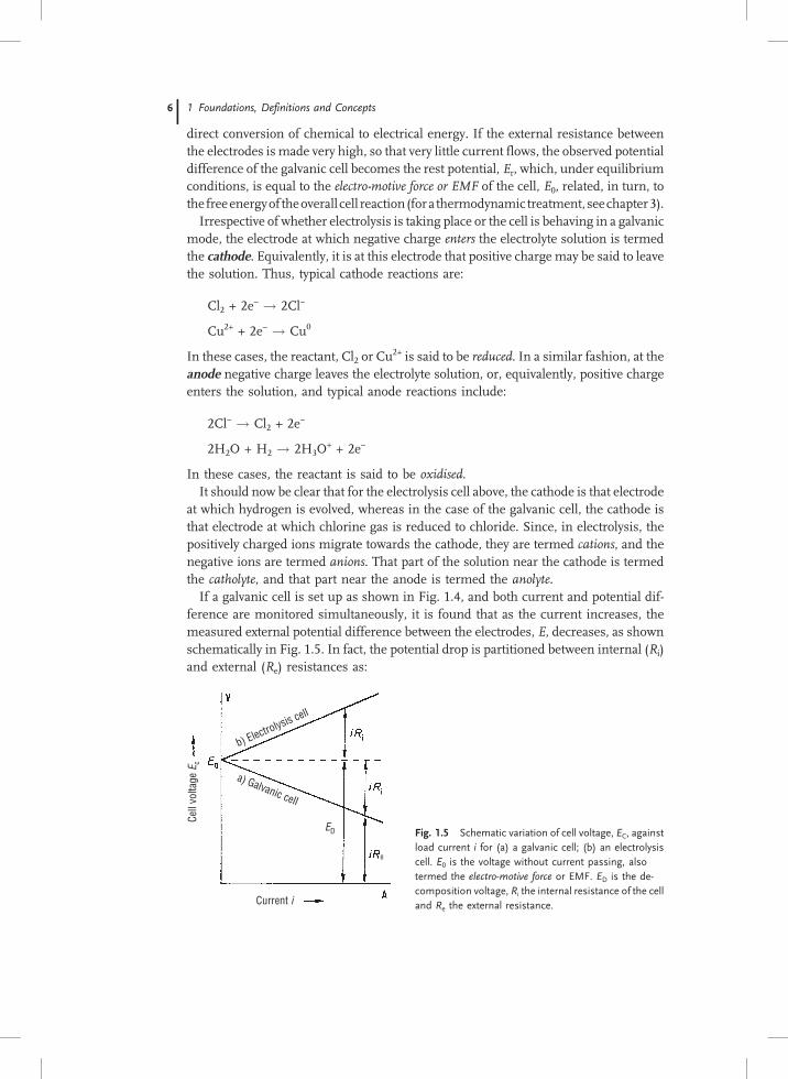
If a galvanic cell is set up as shown in Fig. 1.4, and both current and potential dif-ference are monitored simultaneously, it is found that as the current increases, themeasured external potential difference between the electrodes, E, decreases, as shownschematically in Fig. 1.5. In fact, the potential drop is partitioned between internal (Ri)and external (Re) resistances as:
b) Electrolysis cell
a) Galvanic cell
Cell
volta
ge E
c
Current i
e
ED Fig. 1.5 Schematic variation of cell voltage, EC, against
load current i for (a) a galvanic cell; (b) an electrolysis
cell. E0 is the voltage without current passing, also
termed the electro-motive force or EMF. ED is the de-
composition voltage, Ri the internal resistance of the cell
and Re the external resistance.
1 Foundations, Definitions and Concepts6

E0 ¼ iRi þ iRe
E ¼ E0 � iRi
ð1:8Þ
The power output, P, of the cell is clearly the product of potential and current:
P ¼ iE ¼ iðE0 � iRiÞ ð1:9Þ
and this is a maximum for i ¼ E0=2Ri, and E ¼ E0=2.In the case of an electrolysis cell, when the current is forced through the cell, the
potential drop across the inner resistance of the cell must be added to the decomposi-tion potential, ED, so we have
E ¼ ED þ iRi ð1:10Þ
1.4Faraday’s Laws
If each ion is assigned a charge of�ze0, and the electron current in the external circuithas the value ie (which will evidently be equal to the current flow associated with the ionflux of both positive and negative ions, iI), then, at either electrode, the mass of materialconverted by the total charge passing between ionic and electronic conductors must beproportional to this charge. The charge, Q, itself will just be the product of current andtime, i.e. Q = ie � t, so the mass, m, of material that reacts is given by:
m ¼ const:Q ¼ const:ie � t ð1:11Þ
For an ion with unit elementary charge, e0, the total charge passed in oxidising orreducing one mole, QM, is evidently equal to NAe0, where NA is the Avagadro con-stant, and for the conversion of one mole of z-valent ion a charge of zNAe0 will benecessary. The value of the product NAe0 is numerically equal to 96485 Coulombmol-1, and this quantity is termed the Faraday, and denoted by the symbol F. It followsthat the passage of one Coulomb of charge will lead to the conversion of M/(96485z) gof material, where M is the molar mass. As an example, silver metal can be deposited atthe cathode from solutions of AgNO3; the passage of one Coulomb will lead to thedeposition of 107.88/96485 � 1.118 mg of silver metal.
It follows from this that the ratio of the masses of material converted at the twoelectrodes will have the form
m1=m2 ¼ M1=z1
� �
= M2=z2
� �
ð1:12Þ
The ratio M/z is termed the molar mass of an ion-equivalent, and equation (1.12) tellsus that for the passage of equal amounts of charge, the ratio of the masses of materialconverted at the two electrodes is equal to the ratio of the molar masses of the ionequivalents.
The relationships (1.11) and (1.12) were first expressed as laws by Faraday in 1833and are known as Faraday’s first and second laws. Faraday established his laws purelyexperimentally and Helmholtz went on to deduce from this that there must be an
1.4 Faraday’s Laws 77

elementary unit of charge, a fact we have used effectively to derive his laws from atheoretical standpoint.
The quantitative laws found by Faraday can be used in order to determine the totalamount of charge passed in a circuit if we insert a suitable electrolysis cell in the circuitand measure the amount of material formed or deposited at one of the electrodes.Commonly the measurement is carried out by measuring the amount of metal depos-ited as a coating on an inert electrode, such as platinum, or in the form of an amalgamon a mercury cathode. From this mass, m, and from the electrochemical ion-equivalentof the material deposited, the total charge passed is given by
Q ¼ m
M=zFð1:13Þ
In practice, the so-called silver coulometer is normally used for the measurement ofcharge. A silver coulometer consists, in principle, of a platinum crucible which is filledwith ca 30 % AgNO3 solution and into which is inserted a silver rod, as shown inFig. 1.6. The crucible is connected to the negative pole of the circuit and the silverrod to the positive pole, so that passage of charge results in a build up of a silver coat-ing on the inside of the platinum crucible whilst at the same time, silver dissolves asAg+ from the rod. The electrode reactions are:
Platinum Crucible: Agþ þ e� ! Ag0
Silver Rod: Ag0 ! Agþ þ e�ð1:14Þ
Around the silver rod is arranged a porous bag, whose main purpose is to prevent anyparticles that may fall off the silver rod due to mechanical damage from collecting inthe crucible and being weighed as well. By carefully weighing the mass of the cruciblebefore and after passage of charge, the total amount of charge passed can be deter-mined by the expression Q(/Coulomb) = m(/mg)/1.118.
Another type of coulometer, used particularly for the measurement of smallamounts of charge, is the so-call combustion-gas coulometer. In this device, water ismade ionically conducting by addition of Na2CO3, and electrolysed between two pla-tinum electrodes. The electrode reactions are:
Fig. 1.6 Schematic construction of a silver coulometer
for determination of the total quantity of electricity
passed.
1 Foundations, Definitions and Concepts8

Cathode: 2H2Oþ 2e� ! H2 þ 2OH�
Anode: 2OH� ! H2Oþ 1=2O2 þ 2e�
Overall cell reaction: H2O! 1=2O2 þH2
ð1:15Þ
The mixture of O2 and H2 produced is termed ‘combustion gas’, and is determinedvolumetrically.
It is evident that the current passed during the measurement need not be constantwith time, since the amount of material deposited or converted at the electrode de-pends solely on the integral of the current with respect to time. In measurementsusing modern electronic equipment, the charge Q ¼
R
idt is determined by integra-tion of the accurately measured current and displayed directly.
Accurate measurement of charge is necessary above all in the analytical technique ofcoulometry, in which either the material to be analysed is converted completely into aform suitable for weighing, or is converted into a species that can be determined vo-lumetrically. Further information can be found in Chapter 10 and in the referencescited there on analytical chemistry.
1.5Systems of Units
The fundamental quantities measured in electrochemical studies are current, chargeand voltage, the latter being the potential difference between two defined points in acircuit. The current itself is often replaced by the current density, defined as the currentper unit area of electrode surface.
From the discussion above, it is obviously possible to use Faraday’s laws to relatecurrent and charge to mass and time. This gives rise to the ‘practical internationalelectromagnetic’ system of measurement, in which the ampere is defined as that cur-rent which, flowing for one second, deposits 1.118 mg of silver in a silver coulometer.In this system, the unit of potential difference, the volt, is fixed by reference to thepotential difference of the ‘Weston’ cell, an easily prepared galvanic cell which is de-scribed in detail in section 4.11. The potential difference of the Weston cell is definedto be 1.01830V at 20�C. The unit of electric field strength is the volt per centimetre, andis defined as the gradient of the potential at any given point. It is clearly a vector quantity,in contrast to potential, which is a scalar.
The connection between the electrical current, I flowing through a simple electronicconductor, and the potential difference, V, applied between its ends is given by Ohm’slaw:
V ¼ IR ð1:16Þ
where R is termed the resistance and is strongly dependent on the material from whichthe conductor is made. Its unit is the ohm (X) � V A-1, and the value is defined by theresistance of mercury. In fact, a column of mercury of 1mm2 cross-section and length106.300 cm at 0oC and 1 atm pressure (� 101325 Pa) is defined as having a resistance
1.5 Systems of Units 99

of one ohm. The necessity of specifying cross-section and length arises because theresistance of any material can be factored into two components, one dependent on theintrinsic properties of that material and one dependent on the geometry of the parti-cular sample. For samples of uniform cross-sectional area A, and length l, it is easilyshown that
R ¼ qðl=AÞ ð1:17Þ
where q is termed the resistivity of the material and has the units ohm-cm.Although this system of units is quite internally consistent, there was considerable
pressure from professional organisations and learned journals for the universal use ofa system based on the ampere as the basic electrical unit, with mass, length and timebeing in units of kg, metre and second. The basic units of this internationally agreedsystem, the ‘Systeme International d’Unites’ or SI system, are defined in Table 1.1.This set of units is the preferred set for scientific publishing, but the reality is that theolder units, particularly those based on the unit of length one centimetre and unit ofweight one gram are exceedingly well established, especially in the secondary literatureof compilations of physical quantities; both sets will be used throughout this book, andthe inter-relationships described where appropriate.
In the S.I. system of units, the unit of potential difference is still the volt, but it is nowdefined in terms of the units of energy, the joule or kg m2 s-2 and current: in fact, 1V�1 joule/(1 ampere second). The unit of resistance is similarly defined as 1 ohm � 1volt/1 ampere. In this system, the unit of resistivity should now be the ohm-metre.However, it should be again emphasised that the overwhelming number of valuesquoted in the older literature are in the units of ohm-cm, and caution should beused in importing literature values into the formulae quoted.
Table 1.1 The International System of Units.
Quantity Unit Symbol Definition (abridged)
Length metre m The length of path travelled by light in vacuum during a time
interval of 1/299 792 458 of a second
Mass kilogram kg The mass of a piece of platinum-iridium kept in Sevres.
Time second s 9 192 631 770 periods of the radiation corresponding to thetransition between the hyper-fine levels of the ground state
of the 133Cs atom.
Electrical
Current
ampere A The current that produces a force of 2.10-7 newton per metre
of length between two infinitely long negligibly thick parallelconductors 1 metre apart in vacuo.
Thermo-
dynamictemperature
kelvin K The fraction 1/273.16 of the thermodynamic temperature of
the triple point of water.
Amount ofsubstance
mole mol The amount of substance of a system containing as manyspecified elementary entities (atoms, molecules, ions etc) as
there are atoms in 12g of 12C.
1 Foundations, Definitions and Concepts10

Two units of concentration are used in the rigorous SI system. The concentrationper unit volume has units mol m-3 (mole per cubic metre), and denoted by c. However,the subsidiary unit of dm3 (known familiarly as the litre) is permitted, and concentra-tions of solutions are often quoted in units of mol dm-3, and denoted by the symbol Mthe molarity of the solution. Whilst it is correct to refer to a solution as having con-centration xM, the concentration units used in rational S.I. formulae must be the(rational) mol m-3.
The second unit of concentration has units of mol kg-1, i.e. moles per kg of solvent.This is the more useful measure of concentration when considering the thermody-namics of solutions, as will become apparent below, and it has the further advantageof being independent of temperature, but it is less useful from the practical pointof view. For dilute solutions in water at 25�C, to a high degree of accuracy, a solutionof x mol kg-1 is very close to xM or to 1000x mol m-3. For dilute solutions in othersolvents, a molality of x mol kg-1 will correspond to a concentration of qsx mol m-3,provided the density of the solvent, qs, is expressed in kg m-3.
In order to ensure that equilibrium constants involving concentrations of reactantand product do not possess units themselves, all concentration terms in such formulaeare expressed as ratios of the molarity or molality to a standard value, usually writtenc0 or m0. The choice of m0 is straightforward, and is invariably taken as one mol kg-1.The choice of c0 is less obvious, since values of one mol m-3 or one mol dm-3 might bechosen. Conventionally, the latter has been used, leading to some confusion in for-mulae. To avoid this, we shall use molality as the main unit of concentration inthis book, save in those areas, such as electrolyte conductivity, where volume-basedunits are normally used.
Although this discussion of units may seem quite dry, it actually has considerablepractical importance. It should become second-nature to check any formula for con-sistency of units, a process that is immeasurably helped by having a rational system ofunits in the first place. Unfortunately, the unit of concentration remains a problem; theunit of molarity is deeply ingrained in chemical practice, and cannot be erased easily.This is a particular problem in the development of solution thermodynamics, and thechoice of standard states remains a real difficulty, for which the only remedy is con-stant caution. Let the reader be warned!
References for Chapter One
The most useful background reading is in ele-mentary physics and physical chemistry, and thetextbooks listed below are intended to providesome further material on electricity and electricalmeasurements.
A good background text in physics is:
R. Muncaster: “‘A’-level Physics”, 3rd. Edition,Stanley Thornes (Publishers) Ltd, 1989.
More advanced but with a wealth of illustrativematerial is:
D. Halliday, R. Resnick and K.S. Krane: “Physics”,Volume 2, 4th Edition, John Wiley and Sons Inc.,1992.
The best introductory text in physical chemistry atthis level is
P.W. Atkins: “Introduction to Physical Chemi-stry”, Oxford University Press, 1998.
1.5 Systems of Units 1111