1 Final publishable summary report - TRIMIS€¦ · 1 Final publishable summary report 1.1...
39
1 Final publishable summary report 1.1 Executive Summary SUSTRAIL is the acronym for the EU Framework 7 collaborative research project with grant number 265740. It addressed theme SST.2010.5.2-2: “The sustainable freight railway: Designing the freight vehicle – track system for higher delivered tonnage with improved availability at reduced cost”. The aim of the SUSTRAIL project was “to contribute to the rail freight system to allow it to regain position and market”. To achieve this, a consortium of European experts was formed and considered combined improvements in both freight vehicle and track components in a holistic approach including economic assessments. Achieving a higher reliability and increased performance of the rail freight system as a whole contributes to an increased profitability for all stakeholders making rail freight more attractive. This final report provides a summary of work that occupied almost 70 person-years. In the context of strong growth in road transport and a forecast growth in volumes of freight its aim was “to contribute to the rail freight system to allow it to regain position and market”, aligned with a target of the European Commission. The project was undertaken by a balanced consortium of infrastructure managers (IMs), freight operators, companies involved in the rail sector, and academics. SUSTRAIL considered a combined improvement in both freight vehicles (with a targeted increased in speed and axle-load) and track components (for higher reliability and reduced maintenance), and also the interactions between them. A holistic approach was adopted; benefits to freight and passenger users (since mixed routes were considered) were quantified through the development of appropriate business cases to ensure profitability for all stakeholders. The project activities culminated with the demonstration of the innovations studied for the freight vehicle and track components carried out in the last period of the project. It should be highlighted here that after a significant effort produced for the design and simulation, a prototype vehicle has been built and ran on a test track to establish the viability of the vehicle innovations. This prototype vehicle shown excellent results in terms of fulfilment of the requirements set at the beginning of the project and is available for future developments for a sustainable and efficient freight transport. 1.2 Summary Description of Project Context and Objectives SUSTRAIL is the acronym for the EU Framework 7 collaborative research project with grant number 265740. It addressed theme SST.2010.5.2-2: “The sustainable freight railway: Designing the freight vehicle – track system for higher delivered tonnage with improved availability at reduced cost”. In the context of strong growth in road transport and a forecast growth in volumes of freight its aim was “to contribute to the rail freight system to allow it to regain position and market” (Description of Work), aligned with a target of the European Commission. The project was undertaken by a balanced consortium of infrastructure managers (IMs), freight operators, companies involved in the rail sector, and academics. SUSTRAIL considered a combined improvement in both freight vehicles (with a targeted increased in speed and axle-load) and track components (for higher reliability and reduced maintenance), and
Transcript of 1 Final publishable summary report - TRIMIS€¦ · 1 Final publishable summary report 1.1...
1 Final publishable summary report
1.1 Executive Summary
SUSTRAIL is the acronym for the EU Framework 7 collaborative research project with grant
number 265740. It addressed theme SST.2010.5.2-2: “The sustainable freight railway: Designing the
freight vehicle – track system for higher delivered tonnage with improved availability at reduced
cost”.
The aim of the SUSTRAIL project was “to contribute to the rail freight system to allow it to regain
position and market”. To achieve this, a consortium of European experts was formed and considered
combined improvements in both freight vehicle and track components in a holistic approach
including economic assessments. Achieving a higher reliability and increased performance of the rail
freight system as a whole contributes to an increased profitability for all stakeholders making rail
freight more attractive. This final report provides a summary of work that occupied almost 70
person-years.
In the context of strong growth in road transport and a forecast growth in volumes of freight its aim
was “to contribute to the rail freight system to allow it to regain position and market”, aligned with a
target of the European Commission. The project was undertaken by a balanced consortium of
infrastructure managers (IMs), freight operators, companies involved in the rail sector, and
academics.
SUSTRAIL considered a combined improvement in both freight vehicles (with a targeted increased
in speed and axle-load) and track components (for higher reliability and reduced maintenance), and
also the interactions between them. A holistic approach was adopted; benefits to freight and
passenger users (since mixed routes were considered) were quantified through the development of
appropriate business cases to ensure profitability for all stakeholders.
The project activities culminated with the demonstration of the innovations studied for the freight
vehicle and track components carried out in the last period of the project. It should be highlighted
here that after a significant effort produced for the design and simulation, a prototype vehicle has
been built and ran on a test track to establish the viability of the vehicle innovations. This prototype
vehicle shown excellent results in terms of fulfilment of the requirements set at the beginning of the
project and is available for future developments for a sustainable and efficient freight transport.
1.2 Summary Description of Project Context and Objectives
SUSTRAIL is the acronym for the EU Framework 7 collaborative research project with grant
number 265740. It addressed theme SST.2010.5.2-2: “The sustainable freight railway: Designing the
freight vehicle – track system for higher delivered tonnage with improved availability at reduced
cost”. In the context of strong growth in road transport and a forecast growth in volumes of freight its
aim was “to contribute to the rail freight system to allow it to regain position and market”
(Description of Work), aligned with a target of the European Commission. The project was
undertaken by a balanced consortium of infrastructure managers (IMs), freight operators, companies
involved in the rail sector, and academics.
SUSTRAIL considered a combined improvement in both freight vehicles (with a targeted increased
in speed and axle-load) and track components (for higher reliability and reduced maintenance), and
also the interactions between them. A holistic approach was adopted; benefits to freight and
passenger users (since mixed routes were considered) were quantified through the development of
appropriate business cases to ensure profitability for all stakeholders.
During the initial phase of the project we studied the context into which the SUSTRAIL innovations
would be introduced. We analysed the regulatory framework that any innovations in track or vehicle
should comply with, particularly the six Technical Standards for Interoperability (TSI) relevant to the
SUSTRAIL project and the UIC leaflets on standard construction measures and operating
procedures. Also, due to the diversity of the European rail freight industry, thorough benchmarking
studies were carried out at three diverse freight systems, operating on routes in Spain, Bulgaria, and
the UK. The future logistics requirements for freight on these three routes were analysed.
A particular effort was dedicated to the Business Case for the SUSTRAIL project. It was integrated
into the project early on, with duty requirements defining what the rail industry needs and would
benefit from (in terms of technical innovations in the vehicle and track) to meet the overall objective
of increasing the traffic and market share of rail freight. The key technical innovations proposed
within the project were assessed using: LCC (Life Cycle Cost), RAMS (Reliability, Availability,
Maintainability, and Safety), and cost benefit analyses.
The duty requirements included: optimizing axle load limits, increasing freight operating speeds,
reducing energy use, and reducing forces causing damage to the track. Other factors were also taken
into account such as improved aerodynamics, environmental noise mitigation and easy integration
with the existing fleet, maintenance procedures and safety standards. The cost-benefit analysis
included financial analysis of the impact on IMs, train operators, end users, and government and a
socio-economic cost-benefit analysis covering all parties.
Since innovations cannot be considered truly useful if they are not implemented, it was also
important to consider the potential barriers to their implementation and demonstrate reasons to adopt
them; part of this was considering the financial interface between IMs and freight operators.
Rolling stock innovations were proposed to improve vehicle design resulting in reduced operating
costs for both vehicle and track, and reduced environmental impact. One of the main rolling stock
innovations developed as part of the project was the SUSTRAIL Freight Bogie (patent pending).
This was based on the established Y25 type bogie and incorporated the following technologies:
Double ‘Lenoir link’ primary suspension to improve the curving properties of the system
and reduce damage to the track
Interconnecting links providing longitudinal and lateral stiffness between the axle boxes (to
improve running behaviour and reduce wheel wear)
Noise reduction technologies: brake disks, and spring inserts
Braking system: brake discs, redundant pneumatic back-up system, wheel-slide protection
Condition Monitoring: weighing valves installed in the bogie for local load monitoring;
electro-pneumatic braking control with diagnostic functionality; thermocouple and
accelerometers on each axle box
Power Supply: Bearing generator with battery back-up and intelligent power management
Reduced weight: use of high strength steels, and optimised section designs
Protective axle coating
Computer simulations were used to assess various combinations of the technology improvements and
to establish critical speeds and optimal design parameters for the new primary suspension system.
Other analyses and tests were carried out as appropriate: e.g. both ballistic tests and non-destructive
tests were carried out on axles with and without the coating; finite element analysis of the bogie.
Regarding the vehicle structure, the project aimed to develop an adaptable, intermodal flat wagon,
addressing three main design criteria: lightweight; increased capacity; and sustainable, low-cost
solutions (including recycled materials and interchangeable components). The vehicle body used
novel high strength steel grades and cold formed profiles, optimised spigot disposition, sustainable
flooring material, and lightweight covers.
Other innovations that did not feature on the vehicle were studied as ‘virtual demonstrators’. These
included:
Measures for reducing aerodynamic drag including logistics aspects of loading
Options for locomotive traction
Friction control: recognised to reduce environmental pollution, vibration, noise, and the cost
of operation and maintenance; tests were carried out on the effect of friction modifiers in the
contact zones of both wheel and rail, and wheel and brake shoes.
Monitoring the structural integrity of axles (using low-frequency vibrations and acoustic
emissions).
Energy harvesting systems for powering condition monitoring equipment
Infrastructure Innovations were also considered to improve the resilience of the infrastructure
system, reduce costs, and improve track accessibility. There was a strong link between this work and
the vehicle work since the vehicle design directly affects track deterioration and vice versa. The
work considered many aspects of infrastructure: rail, support (including ballast, transitions, and
reinforcements), switches and crossings, and wayside condition monitoring. Innovations were
selected by the infrastructure managers using a ‘failure modes and effects analysis’ (FMEA).
Following this, a wide range of testing and simulation work was undertaken to produce models,
recommendations, and procedures.
A few highlights:
development of ‘Minimum Action Rules’ for corroded rail
mechanical testing of insulated joints
the use of advanced rail materials to combat wear, and rolling contact fatigue
testing of lubricants for slide plates
optimisation of the support stiffness in the area of the crossing panel (under-sleeper pads)
optimising transitions
vehicle defects that can be detected by dynamic force monitoring and associated maintenance
limits
The SUSTRAIL prototype vehicle has been built and laboratory and track tests to establish the
viability of the innovations it incorporates were carried out in the last period of the project.
As well as the SUSTRAIL prototype vehicle, four track innovations have been tested on mainline
infrastructure:
Premium rail steel
Earthwork-stabilising geo-textiles with inbuilt monitoring sensors
Under-sleeper pads
Wayside monitoring of vehicles
Other innovations included modelling approaches and monitoring equipment that could reduce
uncertainties and result in more robust maintenance regimes for track, switches and crossings, and
associated structures.
1.3 Description of the Main S&T Results/Foregrounds
1.3.1 SUSTRAIL Context
This chapter contains a summary of the main results achieved in Workpackage 1 “Benchmarking”
and Workpackage 2 “Duty Requirements”. The aim of WP1 was “to provide information to support
evaluation of the key system parameters which will ultimately influence and determine
improvements towards freight sustainability and competitiveness”, while WP2 was to “define duty
requirements for vehicles and track to potentially double the life of track components when
combined with low impact vehicles”.
1.3.1.1 Benchmarking
SUSTRAIL Workpackage 1 aimed to provide a benchmark of the current freight ‘system’ to
establish the existing ‘zero state’ for subsequent comparative and enhancement activities. The
benchmarking was designed to provide information to support evaluation of the key system
parameters that will ultimately influence and determine improvements towards freight sustainability
and competitiveness.
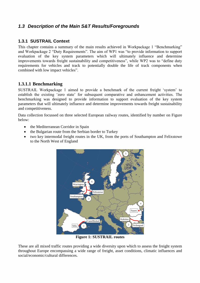
Data collection focussed on three selected European railway routes, identified by number on Figure
below:
the Mediterranean Corridor in Spain
the Bulgarian route from the Serbian border to Turkey
two key intermodal freight routes in the UK, from the ports of Southampton and Felixstowe
to the North West of England
1 2
3
4
5
6
Castellbisbal
Silla
Southampton
Felixstowe
Warrington
Kalotina
Svilengrad
Faurei
Figure 1: SUSTRAIL routes
These are all mixed traffic routes providing a wide diversity upon which to assess the freight system
throughout Europe encompassing a wide range of freight, asset conditions, climatic influences and
social/economic/cultural differences.
Also, tests and measurements were carried out at the test track at AFER’s Railway Testing Centre
Faurei (route 4, not to scale), which is the site of for demonstrations in Work Package 6.
Workpackage 4 made use of data from the Malmbanan heavy iron ore line in the north of Sweden
(route 4 on figure) and the Wooden Gate site on the UK’s East Coast line (route 6, not to scale).
Capacity modelling was conducted to provide benchmarking of the current freight ‘system’, to
establish the existing ‘zero state’ for subsequent comparative and enhancement activities. The
benchmarking is designed to provide information to support evaluation of the key system parameters
that will ultimately influence and determine improvements towards freight sustainability and
competitiveness.
The two categories of wagons most commonly used on the selected routes and beyond, in partner
countries, were flat wagons (as used for carrying containers) and open high-sided wagons. There are
several variations of these that increase the commodities that they can transport.
The ages of wagons in operation, as reported to the SUSTRAIL project, covered a wide range (4 to
37 years). The highest proportion of older wagons (over 30 years) was observed to operate on the
selected route in Spain.
The Y25 bogie and versions thereof was reported to be the most common and widely used for freight
wagons.
Most wagons were equipped with tread brakes / shoe brakes.
1.3.1.2 Future Logistics Requirements
Along the routes, as in the whole of Europe, there had been a steep decline in rail freight carried after
the year 2008. This was an impact of the economic downturn resulting from the financial crisis. In
order to not to draw the wrong conclusions from the development in rail freight along a route both
general and route-specific developments need to be taken into account.
In general it is expected that freight traffic will increase significantly and the European efforts to
increase interoperability and remove barriers to entry will encourage new operators to compete on
the network.
Spain
Currently Spanish rail freight holds only 5% of the land freight market. The Mediterranean Corridor
has the potential to increase capacity, as current freight volumes are significantly low.
This may be achieved through the development of rail freight into new markets alongside car parts
and bulk commodities. A higher market share could also be captured through improved links with
intermodal transport, a move to encourage modal shift from road to rail freight, and integration with
the wider European Network. To accommodate increased freight volumes, it should be possible to
increase train length and the number of wagons per train. Also, increasing freight speed to match that
of passenger trains would reduce problems with their interaction.
If improvements can be made both locally (e.g., double-tracking the whole route) and to its
integration with the European network, then a significant increase in utilisation might be expected.
Bulgaria
Rail freight in Bulgaria has approximately a 10 per cent share of total goods carried by surface
transport. However, the EU has recognised the importance of the route as it has the ability to
transport a wide variety of freight. With improvements to the line, including double tracking
throughout the route, and the rolling stock the increases in capacity and potential are very significant.
There is potential for the average number of wagons per train to increase; however, further research
is needed to clarify any restrictions regarding train length along this route. It is expected that
increasing the average speed of freight along this route from 75 km/h to 120 km/h will lead to an
increase in capacity. However, for such a scheme to be successful, significant investment in
infrastructure along the route would be needed.
The main growth is expected to be of semi-finished and finished goods, textiles, and agricultural
produce from Turkey heading toward Western Europe; it can be expected that the share of goods
transported to and from the plants of the heavy industry, especially the metallurgical industry, will
further diminish. There may be a slight increase in the share of coal and petroleum, as the economic
development of the country of Bulgaria will go hand in hand with an increased use of energy.
United Kingdom
It is estimated that over 25% of freight containers originating from the Far East and shipped into
ports like Southampton and Felixstowe are now transported onwards by rail. In the UK, rail freight
will continue to grow by 26-28% by 2014/2015, compared with the year 2007. Important future
market segments will remain the carriage of coal (for power production), ore (for the steel industry),
and containers (for all kinds of cargo).
Consumer goods transported in containers have been the fastest growing goods category in rail
freight over the past six years. Even the more moderate growth prediction of 4% would underline the
containers’ relevance for rail freight.
Another significant aspect is that there are plans to develop new port facilities at Bathside Bay on the
other side of the estuary near Harwich, which would increase the number of trains from the
combination of Felixstowe and Bathside Bay to 56 trains per day in 2030, which would increase the
share of containerised rail freight.
The future planned expansion of the port of Felixstowe includes a third terminal capable of taking
trains up to 30 wagons in length. In the port of Southampton, there is work underway to increase
maximum train length to 775m. Average train length is therefore expected to increase, and this will
require investment in loops on the network and at terminals.
The demand for Class E ordinary high-sided wagons is still high and will always keep an important
share on the market due to specific types of freight (bulk and aggregates), but the capacity available
from the existing fleets is more than sufficient. An increase in the transportation of biomass is
predicted to take 1/3 to 2/3 of the coal market over the next 15 years. New market segments are most
likely the transportation of high value, low mass goods.
Within WorkPackage 2 an important prioritization methodology was adopted to judge duty
requirements against the objectives: availability; cost; service quality; environmental footprint; and
technical viability. All proposed SUSTRAIL innovations must meet the essential duty requirements
unless a strong case emerges for a change in standards. In addition, SUSTRAIL innovations are
being designed to improve conditions for rail freight in the EU, so the main focus has been on
determining what those improvements should be, in terms of the parameters targeted, the direction of
change, and in some cases where previous research evidence exists, the magnitude of the target. At
the next stage of SUSTRAIL (in WP3, 4, and 5) models were developed to refine these requirements
for improvement and to carry out interim assessments of proposed technologies and engineering
solutions.
Emerging from the prioritisation a set of duty requirements was produced which:
together address the full set of SUSTRAIL objectives. Individually the duty requirements
cannot achieve this: packaging the improvements together is important to achieve the desired
outcome on each objective.
Are judged to offer the best prospect of success within three years’ research, and subsequent
implementation. There is mix of lower- and higher-risk research topics, however the potential
reward also varies. High priority was given to a set of improvements which attempt to
balance these considerations.
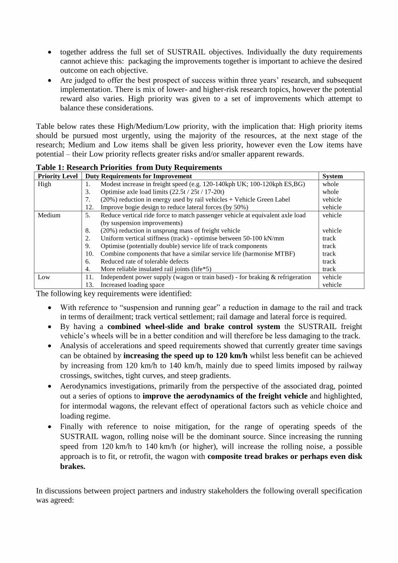
Table below rates these High/Medium/Low priority, with the implication that: High priority items
should be pursued most urgently, using the majority of the resources, at the next stage of the
research; Medium and Low items shall be given less priority, however even the Low items have
potential – their Low priority reflects greater risks and/or smaller apparent rewards.
Table 1: Research Priorities from Duty Requirements Priority Level Duty Requirements for Improvement System High 1. Modest increase in freight speed (e.g. 120-140kph UK; 100-120kph ES,BG)
3. Optimise axle load limits (22.5t / 25t / 17-20t)
7. (20%) reduction in energy used by rail vehicles + Vehicle Green Label
12. Improve bogie design to reduce lateral forces (by 50%)
whole
whole
vehicle
vehicle Medium 5. Reduce vertical ride force to match passenger vehicle at equivalent axle load
(by suspension improvements)
8. (20%) reduction in unsprung mass of freight vehicle
2. Uniform vertical stiffness (track) - optimise between 50-100 kN/mm
9. Optimise (potentially double) service life of track components
10. Combine components that have a similar service life (harmonise MTBF)
6. Reduced rate of tolerable defects
4. More reliable insulated rail joints (life*5)
vehicle
vehicle
track
track
track
track
track Low 11. Independent power supply (wagon or train based) - for braking & refrigeration
13. Increased loading space
vehicle
vehicle
The following key requirements were identified:
With reference to “suspension and running gear” a reduction in damage to the rail and track
in terms of derailment; track vertical settlement; rail damage and lateral force is required.
By having a combined wheel-slide and brake control system the SUSTRAIL freight
vehicle’s wheels will be in a better condition and will therefore be less damaging to the track.
Analysis of accelerations and speed requirements showed that currently greater time savings
can be obtained by increasing the speed up to 120 km/h whilst less benefit can be achieved
by increasing from 120 km/h to 140 km/h, mainly due to speed limits imposed by railway
crossings, switches, tight curves, and steep gradients.
Aerodynamics investigations, primarily from the perspective of the associated drag, pointed
out a series of options to improve the aerodynamics of the freight vehicle and highlighted,
for intermodal wagons, the relevant effect of operational factors such as vehicle choice and
loading regime.
Finally with reference to noise mitigation, for the range of operating speeds of the
SUSTRAIL wagon, rolling noise will be the dominant source. Since increasing the running
speed from 120 km/h to 140 km/h (or higher), will increase the rolling noise, a possible
approach is to fit, or retrofit, the wagon with composite tread brakes or perhaps even disk
brakes.
In discussions between project partners and industry stakeholders the following overall specification
was agreed:
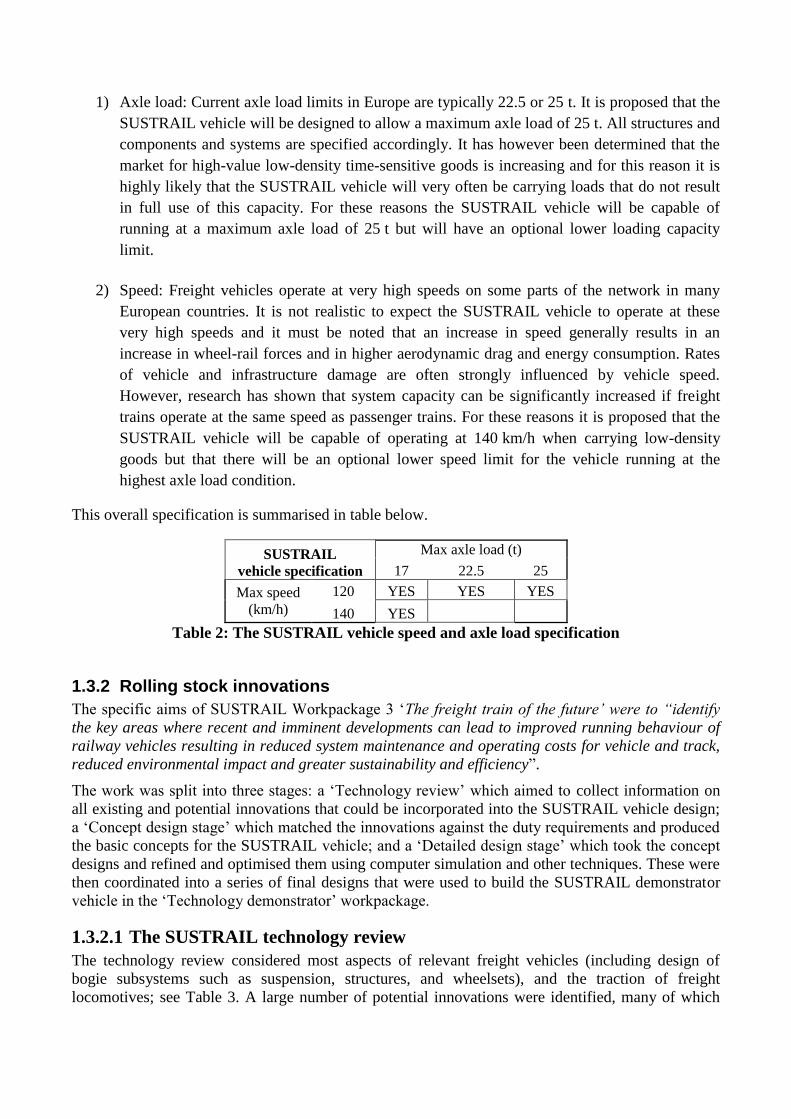
1) Axle load: Current axle load limits in Europe are typically 22.5 or 25 t. It is proposed that the
SUSTRAIL vehicle will be designed to allow a maximum axle load of 25 t. All structures and
components and systems are specified accordingly. It has however been determined that the
market for high-value low-density time-sensitive goods is increasing and for this reason it is
highly likely that the SUSTRAIL vehicle will very often be carrying loads that do not result
in full use of this capacity. For these reasons the SUSTRAIL vehicle will be capable of
running at a maximum axle load of 25 t but will have an optional lower loading capacity
limit.
2) Speed: Freight vehicles operate at very high speeds on some parts of the network in many
European countries. It is not realistic to expect the SUSTRAIL vehicle to operate at these
very high speeds and it must be noted that an increase in speed generally results in an
increase in wheel-rail forces and in higher aerodynamic drag and energy consumption. Rates
of vehicle and infrastructure damage are often strongly influenced by vehicle speed.
However, research has shown that system capacity can be significantly increased if freight
trains operate at the same speed as passenger trains. For these reasons it is proposed that the
SUSTRAIL vehicle will be capable of operating at 140 km/h when carrying low-density
goods but that there will be an optional lower speed limit for the vehicle running at the
highest axle load condition.
This overall specification is summarised in table below.
SUSTRAIL
vehicle specification
Max axle load (t)
17 22.5 25
Max speed
(km/h)
120 YES YES YES
140 YES
Table 2: The SUSTRAIL vehicle speed and axle load specification
1.3.2 Rolling stock innovations
The specific aims of SUSTRAIL Workpackage 3 ‘The freight train of the future’ were to “identify
the key areas where recent and imminent developments can lead to improved running behaviour of
railway vehicles resulting in reduced system maintenance and operating costs for vehicle and track,
reduced environmental impact and greater sustainability and efficiency”.
The work was split into three stages: a ‘Technology review’ which aimed to collect information on
all existing and potential innovations that could be incorporated into the SUSTRAIL vehicle design;
a ‘Concept design stage’ which matched the innovations against the duty requirements and produced
the basic concepts for the SUSTRAIL vehicle; and a ‘Detailed design stage’ which took the concept
designs and refined and optimised them using computer simulation and other techniques. These were
then coordinated into a series of final designs that were used to build the SUSTRAIL demonstrator
vehicle in the ‘Technology demonstrator’ workpackage.
1.3.2.1 The SUSTRAIL technology review
The technology review considered most aspects of relevant freight vehicles (including design of
bogie subsystems such as suspension, structures, and wheelsets), and the traction of freight
locomotives; see Table 3. A large number of potential innovations were identified, many of which
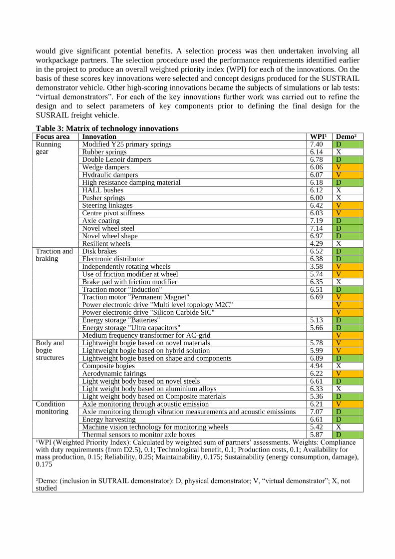
would give significant potential benefits. A selection process was then undertaken involving all
workpackage partners. The selection procedure used the performance requirements identified earlier
in the project to produce an overall weighted priority index (WPI) for each of the innovations. On the
basis of these scores key innovations were selected and concept designs produced for the SUSTRAIL
demonstrator vehicle. Other high-scoring innovations became the subjects of simulations or lab tests:
“virtual demonstrators”. For each of the key innovations further work was carried out to refine the
design and to select parameters of key components prior to defining the final design for the
SUSRAIL freight vehicle.
Table 3: Matrix of technology innovations Focus area Innovation WPI¹ Demo² Running gear
Modified Y25 primary springs 7.40 D Rubber springs 6.14 X Double Lenoir dampers 6.78 D Wedge dampers 6.06 V Hydraulic dampers 6.07 V High resistance damping material 6.18 D HALL bushes 6.12 X Pusher springs 6.00 X Steering linkages 6.42 V Centre pivot stiffness 6.03 V Axle coating 7.19 D Novel wheel steel 7.14 D Novel wheel shape 6.97 D Resilient wheels 4.29 X
Traction and braking
Disk brakes 6.52 D Electronic distributor 6.38 D Independently rotating wheels 3.58 V Use of friction modifier at wheel 5.74 V Brake pad with friction modifier 6.35 X Traction motor "Induction" 6.51 D Traction motor "Permanent Magnet" 6.69 V Power electronic drive "Multi level topology M2C" V Power electronic drive "Silicon Carbide SiC" V Energy storage "Batteries" 5.13 D Energy storage "Ultra capacitors" 5.66 D Medium frequency transformer for AC-grid V
Body and bogie structures
Lightweight bogie based on novel materials 5.78 V Lightweight bogie based on hybrid solution 5.99 V Lightweight bogie based on shape and components 6.89 D Composite bogies 4.94 X Aerodynamic fairings 6.22 V Light weight body based on novel steels 6.61 D Light weight body based on aluminium alloys 6.33 X Light weight body based on Composite materials 5.36 D
Condition monitoring
Axle monitoring through acoustic emission 6.21 V Axle monitoring through vibration measurements and acoustic emissions 7.07 D Energy harvesting 6.61 D Machine vision technology for monitoring wheels 5.42 X Thermal sensors to monitor axle boxes 5.87 D
¹WPI (Weighted Priority Index): Calculated by weighted sum of partners’ assessments. Weights: Compliance with duty requirements (from D2.5), 0.1; Technological benefit, 0.1; Production costs, 0.1; Availability for mass production, 0.15; Reliability, 0.25; Maintainability, 0.175; Sustainability (energy consumption, damage), 0.175
²Demo: (inclusion in SUTRAIL demonstrator): D, physical demonstrator; V, “virtual demonstrator”; X, not studied
It was noted that several of the innovations have been developed to prototype stage in earlier
projects, but very few have been incorporated into production freight vehicles. The main reasons
behind this were considered to be economic (costs of acquisition, monitoring, and maintenance),
with logistical issues of phased introduction and maintenance planning also being relevant. These
aspects were considered for SUSTRAIL’s innovations in the business case workpackage.
1.3.2.2 The SUSTRAIL Bogie
The concept design for the SUSTRAIL freight vehicle bogie presented here includes a number of
significant innovations in the running gear, wheelsets, braking system, bogie structure and in the
adoption of condition monitoring. Despite this, most of the innovations selected are based on proven
technology and this reduces the commercial and operational risks and increases the potential
reliability and overall chances of success of the SUSTRAIL vehicle. In view of the key requirements
of integration of the SUSTRAIL vehicle with the existing fleet and the existing maintenance
procedures and safety standards, the WP3 partners took the decision to base the SUSTRAIL vehicle
on the well-established Y25 type bogie.
Innovations that would integrate with the Y25 comprise:
Double ‘Lenoir link’ primary suspension: in order to improve curving properties of the
system a primary suspension configuration with double Lenoir links (i.e. a link on each of the
springs) was chosen for the SUSTRAIL vehicles. With double Lenoir links the longitudinal
stiffness of the system is reduced and the maximum longitudinal motion between the axle-
box and bogie frame increased compared to a standard Y25 bogie.
Longitudinal linkages: in order to improve the running behaviour of the SUSTRAIL vehicle
it was decided to assess the benefit of linkages providing longitudinal and/or lateral stiffness
between the axle boxes using a radial arm. This was studied in the Infra-Radial project which
aimed to develop a bogie for heavy haul vehicles (axle loads over 25 t) with reduced life
cycle costs. The Infra-Radial tests using the radial arm with four different primary suspension
types showed good results with stable running and radially aligned wheelsets in curves. Wear
of the wheels was seen to reduce significantly.
Centre pivot secondary suspension: the secondary suspension of the Y25 bogie is realised
by a centre pivot bearing and two side bearers. The pivot bearing provides three rotational
degrees of freedom. Between the upper part connected to the carbody and the lower part
connected to the bogie frame there is a plastic layer with a dry-film lubricant defining the
friction and the relative motion without play. The side bearer enables a roll movement
between carbody and bogie frame and provides a frictional damping for yaw movements of
the bogie frame. Overall, this typical secondary suspension for freight wagons is very stiff in
the vertical direction.
Simulations were carried out for a vehicle with double Lenoir links both with and without radial
arms in order to calculate the critical speed. In these simulations wagon movement was simulated on
a straight track with irregularities positioned at the distance of 40 m from the start with velocity
reducing from 160 km/h to 40 km/h. The critical speed was assumed to have been reached when the
total lateral force ( ) dropped below 2.5 kN. Analysing the results of various simulations showed
that:
1) The critical speed for a laden wagon without radial arms is 107 km/h and for a similar empty
wagon it is 80 km/h.
2) The highest critical speed (not less than 140 km/h) can be achieved by the following stiffness of
radial arm:
laden wagon: more than 750 kN/m (critical speed of laden wagon is almost
independent of longitudinal stiffness )
empty wagon: more than 40 kN/m and not more than 250 kN/m or and both
more than 250 kN/m
3) To achieve a critical speed of 140 km/h for the wagon (for either loading condition), the radial
arm should provide 750 kN/m of lateral stiffness. It need not provide any longitudinal stiffness.
As part of the optimisation of the primary suspension other parameters were varied, including the
vertical coil spring stiffness, the ‘angle’ and length of the Lenoir link, the longitudinal offset between
ends, the friction coefficient at the sliding surfaces (through changing material), the vertical
clearance to the bump stop.
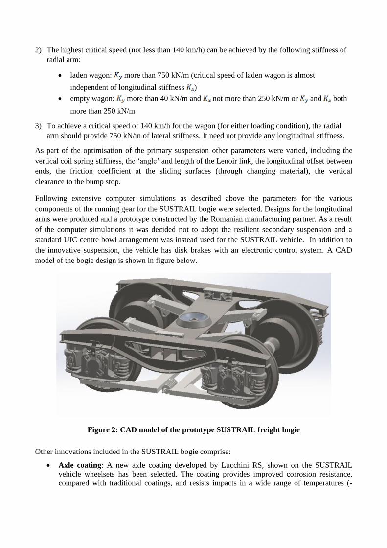
Following extensive computer simulations as described above the parameters for the various
components of the running gear for the SUSTRAIL bogie were selected. Designs for the longitudinal
arms were produced and a prototype constructed by the Romanian manufacturing partner. As a result
of the computer simulations it was decided not to adopt the resilient secondary suspension and a
standard UIC centre bowl arrangement was instead used for the SUSTRAIL vehicle. In addition to
the innovative suspension, the vehicle has disk brakes with an electronic control system. A CAD
model of the bogie design is shown in figure below.
Figure 2: CAD model of the prototype SUSTRAIL freight bogie
Other innovations included in the SUSTRAIL bogie comprise:
Axle coating: A new axle coating developed by Lucchini RS, shown on the SUSTRAIL
vehicle wheelsets has been selected. The coating provides improved corrosion resistance,
compared with traditional coatings, and resists impacts in a wide range of temperatures (-
40°C to 150°C). So, it protects the axle and limits the possibility of crack initiation even
under aggressive conditions; this can reduce maintenance costs.
Friction modifiers: friction modifiers can be used to control or vary the friction coefficient
in different areas of the wheel and rail and tests of their effectiveness were carried out to
establish the potential benefits for the vehicle and track. The laboratory research has shown
the satisfactory properties of the tested friction modifiers for interacting surfaces of wheel and
rail and wheels and brake shoes.
Braking system: The braking system, as with the rest of the SUSTRAIL vehicle, aims to use
recent and imminent innovations to produce an innovative high performance freight vehicle
to allow the vehicle to function at an increased speed of 140 km/h while still delivering
reduced impact and greater efficiency to allow the market needs to be met. The system used
for this project is a combined system containing brake control and wheel-slide protection
functions due to the required basic conditions. For improved availability and safety, these
functions use separate components. Similarly, redundancy was designed into crucial
functional units of the brake control.
1.3.2.3 Vehicle structure
The SUSTRAIL project aimed to develop the outline design of an innovative intermodal flat wagon
that would respond to increased flows of intermodal loading units, which include ISO containers,
swap bodies and semi-trailers, and was flexible and adaptable for other commodities, as well.
The SUSTRAIL vehicle upgrades focused on three criteria:
1. Lightweight design (bogie, frame, overall structure)
Materials selection
Hybrid Solutions (shape, components, dimensions and materials)
Structural design (shape and components)
2. Increased capacity
Greater and more flexible payload
Improved availability
Multi-functionality (different commodities)
3. Sustainable, low cost solutions
Interchangeable and inexpensive components and parts (couplers, wheelsets, buffers,
etc.)
Sustainable materials (e.g. recyclable or recycled)
Reduced maintenance
The innovative wagon concept addressed the following challenges:
Lightweight structural solution
Multi-purpose and flexible structure
Modular design
Commonality and interoperability
Sustainable engineering solutions (in relation to materials, design, and manufacturing)
The design process was guided by the project objective of increasing overall tonnage throughput.
The vehicle outline design, including the detailed designs of its structural parts, considered the
following crucial inputs:
1. The innovative concepts relating to the key challenges for SUSTRAIL freight
wagon (i.e., lightweight, multi-purpose, modular, flexible and sustainable)
2. The duty requirements, specifications, and recommendations from previous
work
3. The boundaries defined by standardisation, regulation, and manufacturing
capabilities
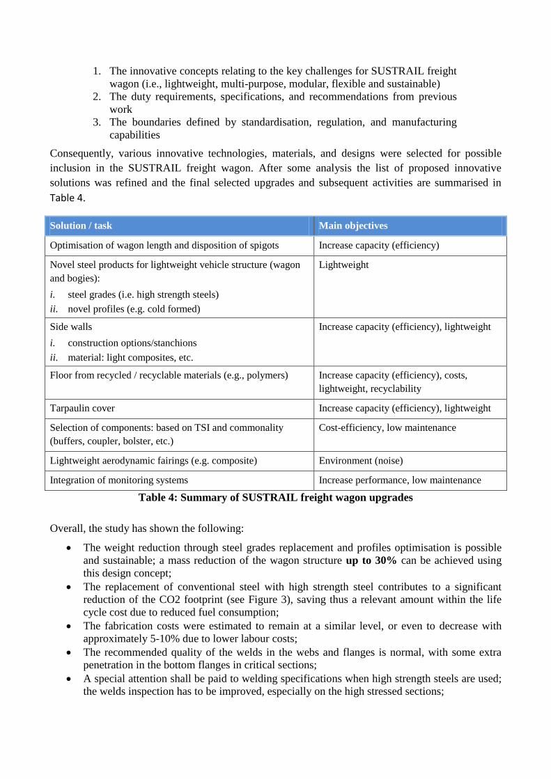
Consequently, various innovative technologies, materials, and designs were selected for possible
inclusion in the SUSTRAIL freight wagon. After some analysis the list of proposed innovative
solutions was refined and the final selected upgrades and subsequent activities are summarised in
Table 4.
Solution / task Main objectives
Optimisation of wagon length and disposition of spigots Increase capacity (efficiency)
Novel steel products for lightweight vehicle structure (wagon
and bogies):
i. steel grades (i.e. high strength steels)
ii. novel profiles (e.g. cold formed)
Lightweight
Side walls
i. construction options/stanchions
ii. material: light composites, etc.
Increase capacity (efficiency), lightweight
Floor from recycled / recyclable materials (e.g., polymers) Increase capacity (efficiency), costs,
lightweight, recyclability
Tarpaulin cover Increase capacity (efficiency), lightweight
Selection of components: based on TSI and commonality
(buffers, coupler, bolster, etc.)
Cost-efficiency, low maintenance
Lightweight aerodynamic fairings (e.g. composite) Environment (noise)
Integration of monitoring systems Increase performance, low maintenance
Table 4: Summary of SUSTRAIL freight wagon upgrades
Overall, the study has shown the following:
The weight reduction through steel grades replacement and profiles optimisation is possible
and sustainable; a mass reduction of the wagon structure up to 30% can be achieved using
this design concept;
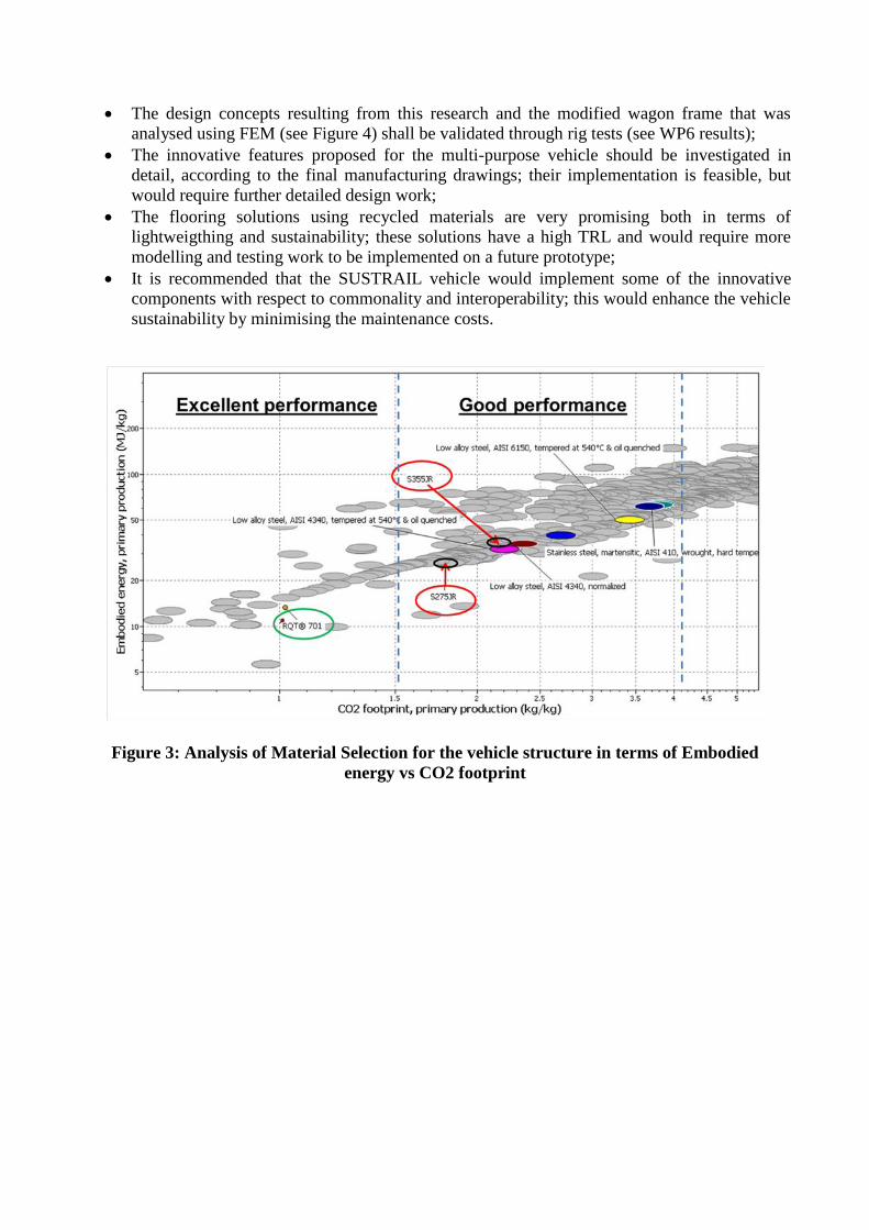
The replacement of conventional steel with high strength steel contributes to a significant
reduction of the CO2 footprint (see Figure 3), saving thus a relevant amount within the life
cycle cost due to reduced fuel consumption;
The fabrication costs were estimated to remain at a similar level, or even to decrease with
approximately 5-10% due to lower labour costs;
The recommended quality of the welds in the webs and flanges is normal, with some extra
penetration in the bottom flanges in critical sections;
A special attention shall be paid to welding specifications when high strength steels are used;
the welds inspection has to be improved, especially on the high stressed sections;
The design concepts resulting from this research and the modified wagon frame that was
analysed using FEM (see Figure 4) shall be validated through rig tests (see WP6 results);
The innovative features proposed for the multi-purpose vehicle should be investigated in
detail, according to the final manufacturing drawings; their implementation is feasible, but
would require further detailed design work;
The flooring solutions using recycled materials are very promising both in terms of
lightweigthing and sustainability; these solutions have a high TRL and would require more
modelling and testing work to be implemented on a future prototype;
It is recommended that the SUSTRAIL vehicle would implement some of the innovative
components with respect to commonality and interoperability; this would enhance the vehicle
sustainability by minimising the maintenance costs.
Figure 3: Analysis of Material Selection for the vehicle structure in terms of Embodied
energy vs CO2 footprint
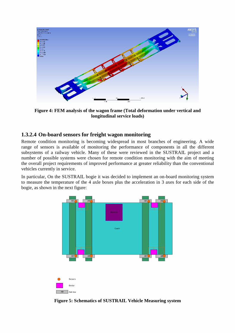
Figure 4: FEM analysis of the wagon frame (Total deformation under vertical and
longitudinal service loads)
1.3.2.4 On-board sensors for freight wagon monitoring
Remote condition monitoring is becoming widespread in most branches of engineering. A wide
range of sensors is available of monitoring the performance of components in all the different
subsystems of a railway vehicle. Many of these were reviewed in the SUSTRAIL project and a
number of possible systems were chosen for remote condition monitoring with the aim of meeting
the overall project requirements of improved performance at greater reliability than the conventional
vehicles currently in service.
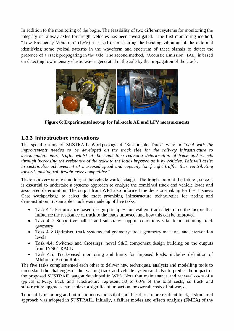
In particular, On the SUSTRAIL bogie it was decided to implement an on-board monitoring system
to measure the temperature of the 4 axle boxes plus the acceleration in 3 axes for each side of the
bogie, as shown in the next figure:
Figure 5: Schematics of SUSTRAIL Vehicle Measuring system
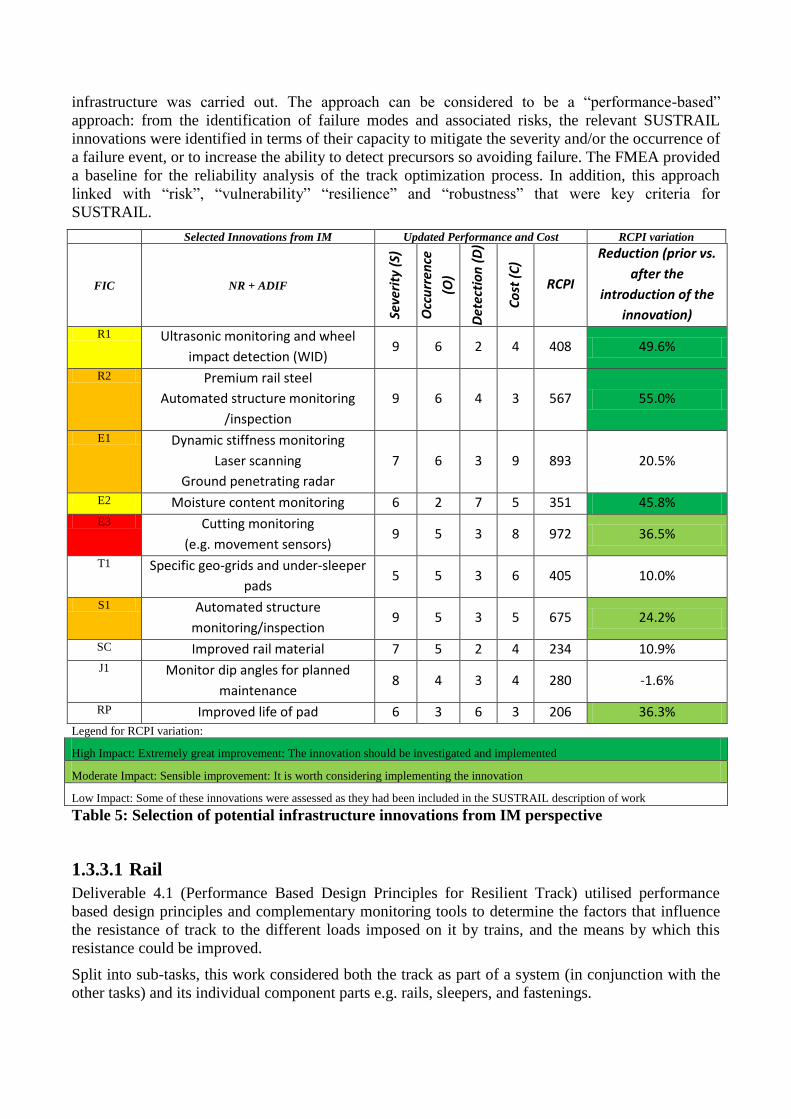
In addition to the monitoring of the bogie, The feasibility of two different systems for monitoring the
integrity of railway axles for freight vehicles has been investigated. The first monitoring method,
“Low Frequency Vibration” (LFV) is based on measuring the bending vibration of the axle and
identifying some typical patterns in the waveform and spectrum of these signals to detect the
presence of a crack propagating in the axle. The second method, “Acoustic Emission” (AE) is based
on detecting low intensity elastic waves generated in the axle by the propagation of the crack.
Figure 6: Experimental set-up for full-scale AE and LFV measurements
1.3.3 Infrastructure innovations
The specific aims of SUSTRAIL Workpackage 4 ‘Sustainable Track’ were to “deal with the
improvements needed to be developed on the track side for the railway infrastructure to
accommodate more traffic whilst at the same time reducing deterioration of track and wheels
through increasing the resistance of the track to the loads imposed on it by vehicles. This will assist
in sustainable achievement of increased speed and capacity for freight traffic, thus contributing
towards making rail freight more competitive.”
There is a very strong coupling to the vehicle workpackage, ‘The freight train of the future’, since it
is essential to undertake a systems approach to analyse the combined track and vehicle loads and
associated deterioration. The output from WP4 also informed the decision-making for the Business
Case workpackage to select the most promising infrastructure technologies for testing and
demonstration. Sustainable Track was made up of five tasks:
Task 4.1: Performance based design principles for resilient track: determine the factors that
influence the resistance of track to the loads imposed, and how this can be improved
Task 4.2: Supportive ballast and substrate: support conditions vital to maintaining track
geometry
Task 4.3: Optimised track systems and geometry: track geometry measures and intervention
levels
Task 4.4: Switches and Crossings: novel S&C component design building on the outputs
from INNOTRACK
Task 4.5: Track-based monitoring and limits for imposed loads: includes definition of
Minimum Action Rules
The five tasks complemented each other to deliver new techniques, analysis and modelling tools to
understand the challenges of the existing track and vehicle system and also to predict the impact of
the proposed SUSTRAIL wagon developed in WP3. Note that maintenance and renewal costs of a
typical railway, track and substructure represent 50 to 60% of the total costs, so track and
substructure upgrades can achieve a significant impact on the overall costs of railways.
To identify incoming and futuristic innovations that could lead to a more resilient track, a structured
approach was adopted in SUSTRAIL. Initially, a failure modes and effects analysis (FMEA) of the
infrastructure was carried out. The approach can be considered to be a “performance-based”
approach: from the identification of failure modes and associated risks, the relevant SUSTRAIL
innovations were identified in terms of their capacity to mitigate the severity and/or the occurrence of
a failure event, or to increase the ability to detect precursors so avoiding failure. The FMEA provided
a baseline for the reliability analysis of the track optimization process. In addition, this approach
linked with “risk”, “vulnerability” “resilience” and “robustness” that were key criteria for
SUSTRAIL.
Selected Innovations from IM Updated Performance and Cost RCPI variation
FIC NR + ADIF
Seve
rity
(S)
Occ
urr
ence
(O)
Det
ecti
on
(D
)
Co
st (
C)
RCPI
Reduction (prior vs.
after the
introduction of the
innovation)
R1 Ultrasonic monitoring and wheel
impact detection (WID) 9 6 2 4 408 49.6%
R2 Premium rail steel
Automated structure monitoring
/inspection
9 6 4 3 567 55.0%
E1 Dynamic stiffness monitoring
Laser scanning
Ground penetrating radar
7 6 3 9 893 20.5%
E2 Moisture content monitoring 6 2 7 5 351 45.8% E3 Cutting monitoring
(e.g. movement sensors) 9 5 3 8 972 36.5%
T1 Specific geo-grids and under-sleeper
pads 5 5 3 6 405 10.0%
S1 Automated structure
monitoring/inspection 9 5 3 5 675 24.2%
SC Improved rail material 7 5 2 4 234 10.9% J1 Monitor dip angles for planned
maintenance 8 4 3 4 280 -1.6%
RP Improved life of pad 6 3 6 3 206 36.3%
Legend for RCPI variation:
High Impact: Extremely great improvement: The innovation should be investigated and implemented
Moderate Impact: Sensible improvement: It is worth considering implementing the innovation
Low Impact: Some of these innovations were assessed as they had been included in the SUSTRAIL description of work
Table 5: Selection of potential infrastructure innovations from IM perspective
1.3.3.1 Rail
Deliverable 4.1 (Performance Based Design Principles for Resilient Track) utilised performance
based design principles and complementary monitoring tools to determine the factors that influence
the resistance of track to the different loads imposed on it by trains, and the means by which this
resistance could be improved.
Split into sub-tasks, this work considered both the track as part of a system (in conjunction with the
other tasks) and its individual component parts e.g. rails, sleepers, and fastenings.
Typical loading on track components for selected critical running vehicle-track combinations has
been defined for rail pad forces; ballast-sleeper interface stresses and sleeper bending stresses, and
sleeper & rail accelerations. This has enabled mechanical component testing and modelling of rail
joints to be undertaken, which has highlighted the impact of rail foot corrosion in this area and the
stress concentrations in the joint components.
Minimum Action Rules have been developed for rail foot corrosion, considering rail types and
corrosion levels, which has proven that the technique can be used to assist in planning inspection
routines and defining the remedial action required following the detection of a defect. Three
corrosion levels were modelled and results reported using un-randomised single model run data to
provide exact figures. The work highlighted that corrosion of even 0.5mm all around the foot has a
significant influence on the lifetime before failure and higher levels of corrosion show even more
severe reductions. The 60E2 rail profile shows more resistance to corrosion over 56E1 profile due to
the increased cross sectional area.
Risk analysis has been undertaken to demonstrate the benefits for Infrastructure Managers to
visualise systems and components performance and subsequent interventions to deliver a high
performing track. This includes estimations for both system and component failure frequencies and
the consequences of failure.
Moving from reactive maintenance, based upon safety limits, to predictive maintenance limits has
been considered using decision support tools and maintenance strategies to determine the most cost
effective points to undertake maintenance activities. This work has included track geometry,
contractor performance and tamping and has identified cost effective intervention limits.
1.3.3.2 Switches and Crossings
Task 4.4 of SUSTRAIL focused on optimising the operation, safety and the reliability of switches
and crossings (S&C). The work began with a technology review, followed by data analysis, model
development, simulation and physical testing. The areas considered were:
Point operating equipment (POE), drive and lock mechanisms
The use of advanced rail materials
Testing of lubricants for slide chairs
The geometrical interface between wheel and crossing
Optimisation of the support stiffness in the area of the crossing panel
The main outcome of the project in the area of drive and locking devices includes a thorough
review of the INNOTRACK recommendations in the context of the SUSTRAIL freight corridors and
supported by a failure analysis specific to those selected freight routes in the UK. Conclusions
converge towards the INNOTRACK recommendation that the current state-of-the-art physical
arrangement for Switch and Crossing (S&C) drive and locking device is to have combined drive,
locking and detection devices integrated into hollow bearers at the main drive locations. This
arrangement permits access to the ballast bays between bearers for mechanical tamping, which
allows for a consistent support conditions to be maintained throughout the S&C unit and adjoining
track which reduces dynamic loads and degradation. Therefore it is recommended that the design
specifications for the physical arrangement, modular design, standardised components and interface
protocols developed by the INNOTRACK should be adopted with condition monitoring of both, the
drive, locking, and detection device itself, and the parameters of the S&C unit which it can measure.
It is anticipated that the adoption of these design specifications with condition monitoring would
increases in the maintainability of the S&C unit and component life, improve reliability through fault
detection and prediction, enable the adoption of efficient condition based preventative maintenance
strategies and eliminate the majority of the types of failures associated with traditional mechanical
linkages. These have been found to be the most common type of failure in the fault and failure data
from the case study route.
In the area of advance materials the main output is strong evidence of the benefit offered by
premium grades of steel to combat the degradation observed on switch blades over their lifetime.
R350HT has demonstrated a high resistance to wear in comparison to R260 grade rail. HP335 has
demonstrated both excellent wear resistance and RCF resistance in a switch blade application.
Bainitic grade BLF320 showed excellent RCF resistance in switch blades however the wear
resistance is similar to that of a pearlitic rail of similar hardness. A second area of further work is
into applications of premium steels into other parts of the crossing such as wing rails and the crossing
nose. Moreover further work is still required to understand the degradation mechanisms. Full
understanding of the degradation mechanisms of premium rail steel in these applications and also
repair in service is needed to allow correct material selection. Furthermore methods of testing of
various lubricants for slide baseplates have been developed and used to determine those lubricants
that performed best under conditions proposed by Network Rail. Significant immediate and the long
term benefits have been demonstrated from the use of advance lubricant with respect to dry condition
and conventional options.
The main outcome of the project in the area of geometrical interface between wheel and rails has
been to further the understanding of the impact of vehicle and wheel shapes on the vertical damage at
crossing panels. The tasks has produced advance simulation algorithms and techniques capable of
handling large set of vehicle and track conditions to help identify those properties in the system
leading to disproportionate damage. For example particular shapes of wheels (e.g. increased conicity)
have been shown to lead to increased vertical force impact and limit values can thus be proposed as
well as automated control techniques can be envisaged in the future based on these results. This work
will be extended in future European projects such as the on-going Capacity4Rail to suggest
optimised wheel and rail shapes and improved support solutions.
The main outcome of the project in the area of support stiffness optimisation has shown through
numerical simulation that the vertical damage in the area of the crossing panel can be improved
under a wide range of track support condition by the addition of resilient layers. The most effective
methods investigated are showing that the use of under sleeper pads can be very effective in limiting
the vertical forces transmitted to the track component and the supporting layers. Furthermore they are
showing the advantage of being very effective at lowering and equalising stresses in the foot of cast
crossings and also reducing significantly the differential stresses on the supporting ballast layers.
1.3.3.3 Substructure
The objective of Workpackage 4.2 was to identify the impacts of substrate stiffness variation on
track geometry deterioration and other track defects such as the effect of vertical plane long
wavelength rail bending on rolling contact fatigue crack growth. The activities focused on the role of
structures such as bridges and embankments, and track substrate stiffness, in enabling the railway to
effectively bear the loads to which it is subjected.
The infrastructure managers (IM) provided detailed site data for use in analyses and described
current desk-based and on-site investigations used to assess the adequacy of trackbed stiffness. The
on-site investigations can be intrusive (digging trial pits) or use a Falling Weight Deflectometer to
assess stiffness and critical speed. It was reported that up to about four times the depth of granular
trackbed layer (maybe a metre) can be required to produce the same dynamic sleeper support
stiffness when running over well-drained soft clay compared to very stiff ground. If good drainage is
not available the expected stiffness will approximately be halved.
IM consider that a stiff trackbed results in better track quality needing less maintenance, resulting in
lower whole life cost. Whilst a stiff track bed results in higher ballast loading, it is clear that this is
within acceptable limits and other benefits from reduced ballast movement results in less ballast
deterioration and therefore increased durability. Very low trackbed stiffness can result in trains
approaching the “critical velocity” when they travel at the same speed as the displacement wave they
generate in the substructure. Unless speed restrictions are introduced this results in rapid
deterioration of track geometry.
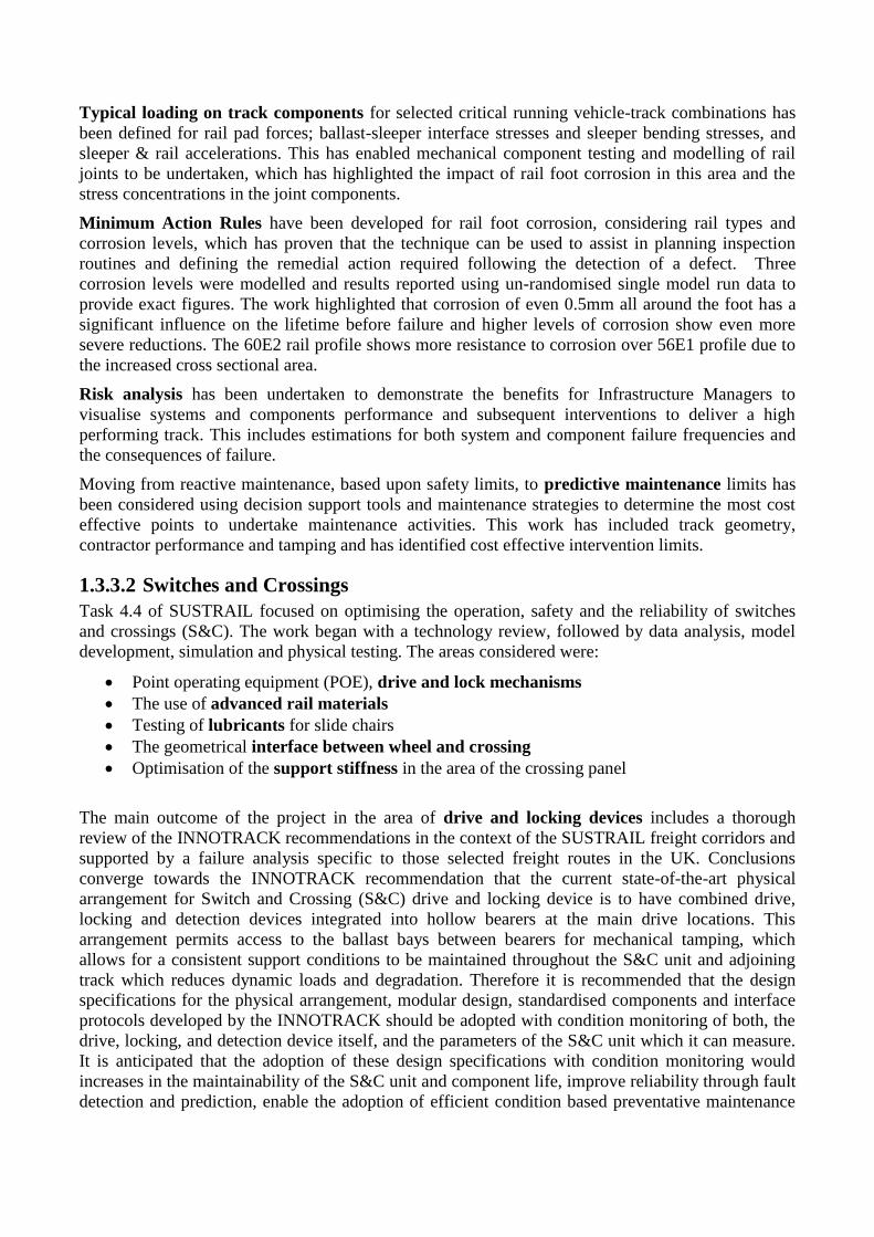
From the data provided by the IMs, a specific section of the Bulgarian line which runs between
Serbia and Turkey was modelled. Data regarding the condition of the track for this site suggests the
track is in a bad condition. An analysis was carried out of a laden vehicle, moving at 120 km/h over
the site. The equivalent stresses in the different layers after 2.1 seconds of simulation are shown in
Figure 7. These pictures clearly show the footpath of the train wheels in the structure and the
propagation and extension of the stress field in the soil layers. Indeed for a soft soil in the subgrade
evidence of the stress induced by the train is quite significant.
Figure 7: Dynamic FEM analysis of railway substructure showing the contours of effective
stress in the different layers: sleepers (top left); ballast (top right); sub-ballast (bottom left) and
substrate (bottom right)
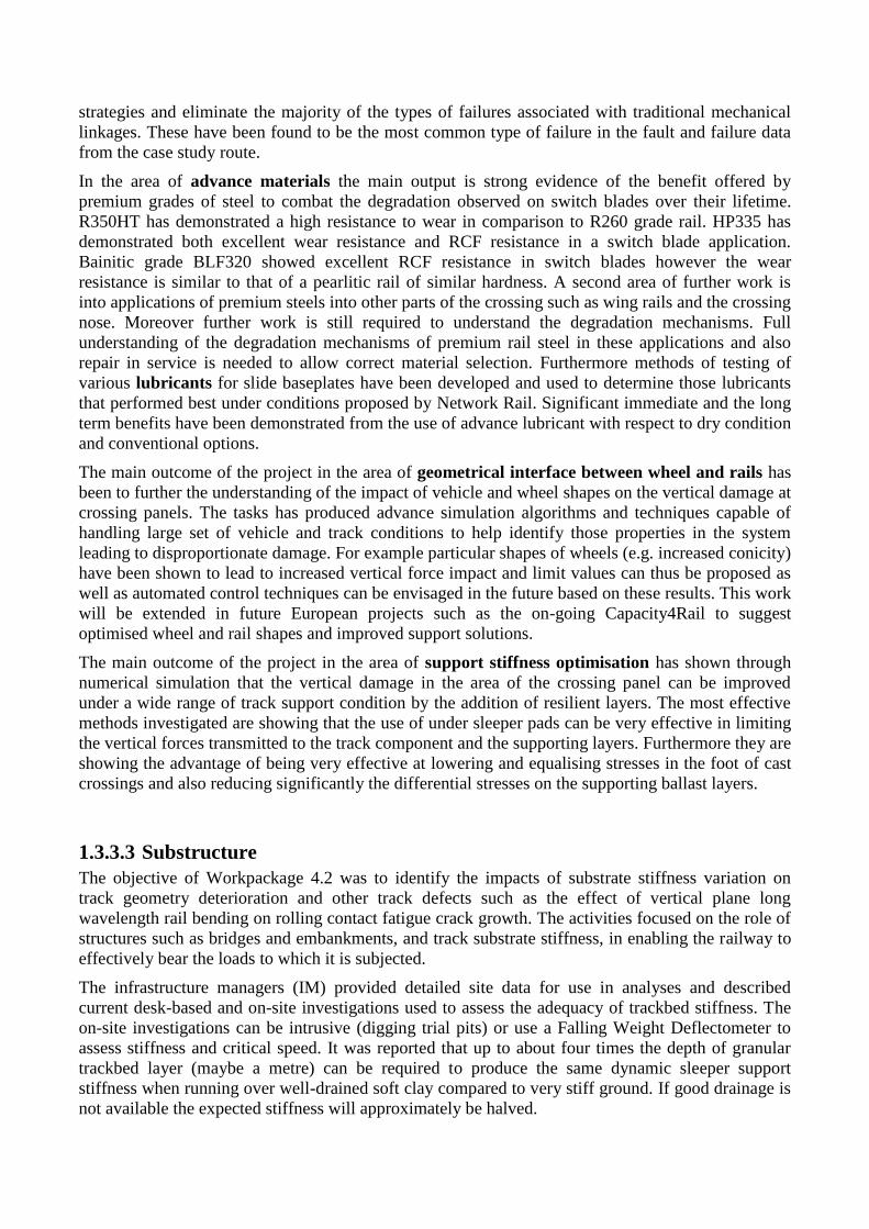
A tool, illustrated in Figure 8, was developed to enable the effect of varying track stiffness to be
assessed. Differential stiffness of sleeper locations was included to model the different force required
to lift a sleeper compared to that to push it into the ballast.
Figure 8: Beam model of rail
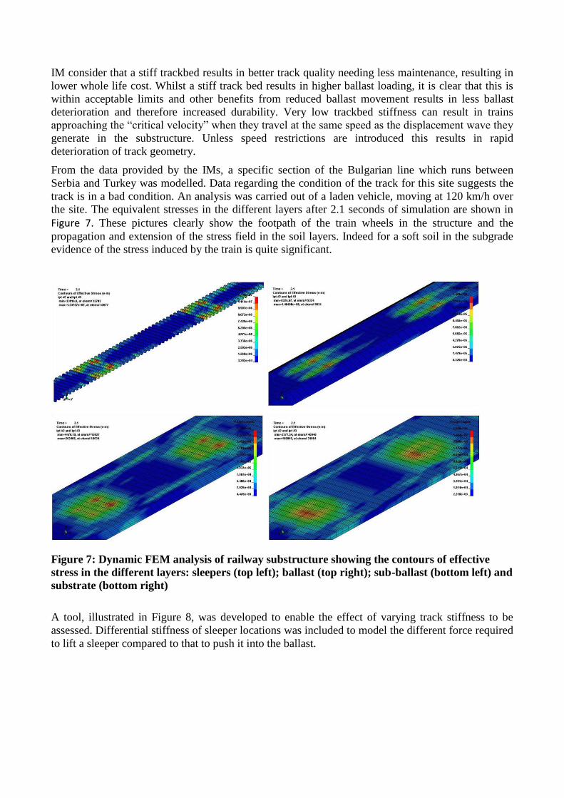
The model was used to assess variuos scenarios of loose and voided sleepers. Figure 9 illustrates a
set of results; the displacements and rail bending moments are shown for a vehicle partway onto a
transition to a stiff foundation (e.g. onto a bridge). The solid green curves show the results for a
uniform foundation. The transition is achieved by doubling the stiffness of only one sleeper (to
100kN/mm) and has resulted in the increase in bending moment halving compared to there being an
abrupt transition. It is also evident from Figure 9 that for each downward bending moment associated
with a wheel load there are upward bending moments in the adjacent sleeper bay; the largest of these
for this scenario occurs between vehicles, where there is the shortest distance between wheels, and
has a magnitude about half that of the downward bending moment.
Figure 9: Vehicle passing over ramped transition to stiff support
SS
Sleepers modelled with
both support and
moment stiffness
SS SS
Wheelba
se
Wheel loads applied
at relevant locations
Location is variable
Additional bogies and
vehicles included as
necessary
Vertical rail displacement
is piecewise cubic plus
load terms
SS=Sleeper spacing (can be
variable)
1.3.3.4 Wayside condition monitoring
The objective of Workpackage 4.5 was to identify monitoring tools to increase the lower bound of
the track resistance probability curve through removing the causes of track failures at discrete
locations with low damage resistance. The work included an identification of technologies that can
be used to monitor infrastructure and vehicles to optimise preventative and intervention-level
maintenance strategies. There are several different technologies used to measure loads imposed by
vehicles on the railway infrastructure, different implementations of them, and the intervention levels
and action requirements applied vary from one member state to another.
The use of axle load checkpoints (ALC) can be motivated by different aims and so be operated in
different ways. For infrastructure managers, the aims could be the protection of infrastructure from
high loads, or potentially dangerous vehicles (for example those with a high potential for
derailment), the loading on the infrastructure imposed by running vehicles, or local degradation of
the infrastructure.
SUSTRAIL exploited the availability of a wayside monitoring station installed on the Swedish iron
ore line Malmbanan through the partner DAMILL. The data provided is used to suggest
maintenance alarm limits for different parameters that are related to different vehicle defects.
Maintenance alarm limits are triggered earlier than safety alarms limits and do not require such
precise measurements (under normal degradation rates there is time to measure the same vehicle
several times before deciding on the action to be taken). They are supposed to identify an optimal
time, based on economics, when it is advisable to bring vehicles into a workshop instead of leaving
them to degrade (and potentially damage track) further.
1.3.4 Business Case
SUSTRAIL Workpackage 5 ‘Business Case’ was linked to the vehicle (WP3) and track (WP4)
workpackages whose main results were presented above. The specific aims were to “consider the
economic business case and implementation issues associated with the vehicle and track options
developed in WP3 and WP4 respectively. Amongst other aspects, the Workpackage will act as both
an iterative filter for the options developed in WP3 and WP4 in order to help focus the engineering
development to those options which are likely to have greatest overall net benefits, as well as
providing a final business case appraisal for the preferred option.”
The SUSTRAIL project is more than technical innovations. At all stages within the project there has
been involvement of disciplines such as economics, and human factor analysts, and substantial
stakeholder engagement. This is important to ensure that the engineering research is directed at areas
which best meet the overall objective of the project, namely to improve the competitiveness of rail
freight. The Business Case workpackage contributes to the overall project objective by
helping to prioritise innovations for final assessment
aiding the project to identify means to integrate the engineering innovations into the industry,
including phasing in of novel technologies
developing strategies for the equitable redistribution of whole-system savings
helping promote and facilitate industry, government, and other stakeholders’ ‘buy-in’
To this end, work to understand what is needed by the rail freight industry (in terms of technical
innovations in the vehicle and track) to meet the overall policy objective of increasing the market
share of rail freight, was embedded within the early stages of the SUSTRAIL project; in order to
meet its objectives, the engineering research had to align and be optimised to this end.
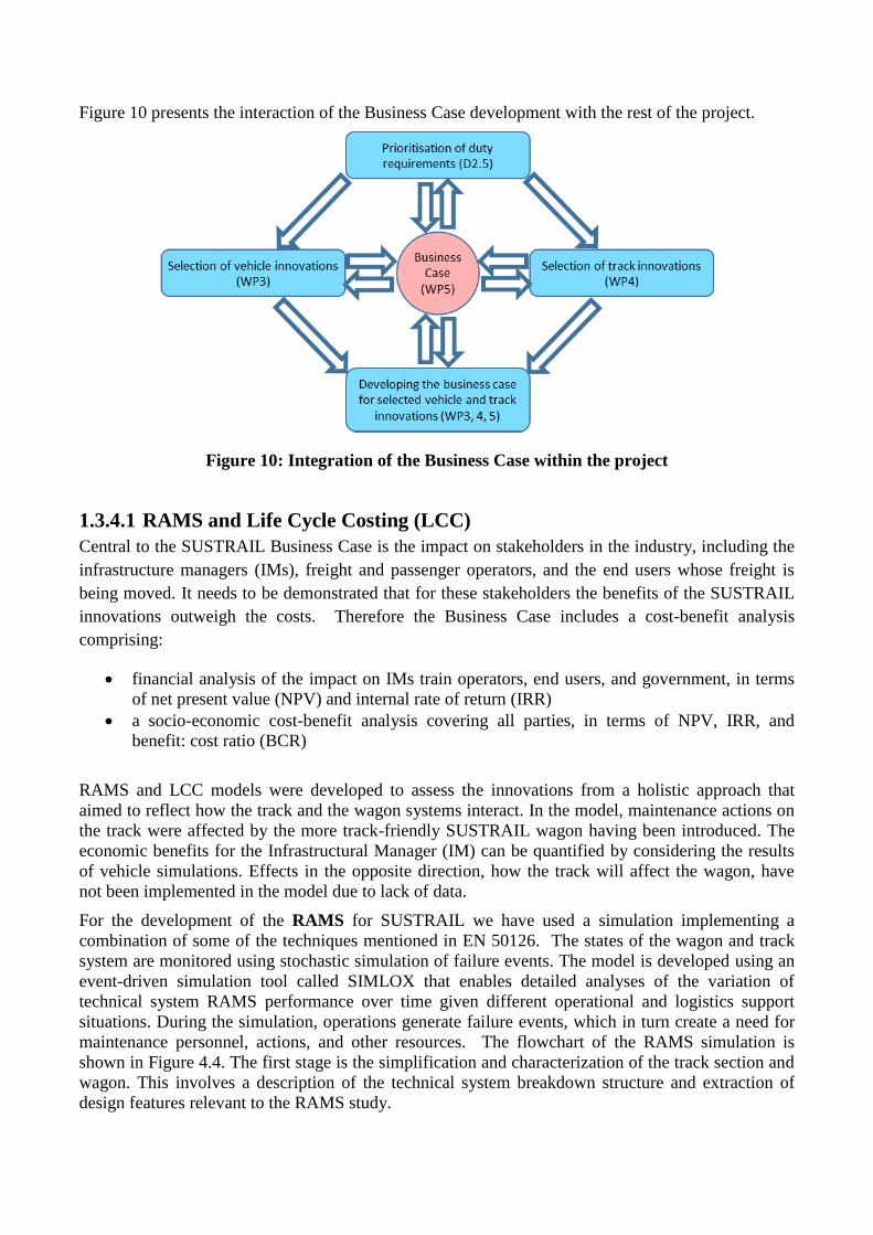
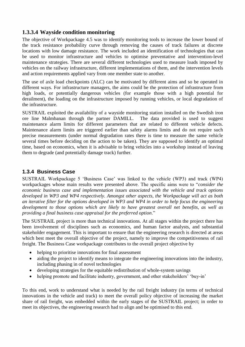
Figure 10 presents the interaction of the Business Case development with the rest of the project.
Figure 10: Integration of the Business Case within the project
1.3.4.1 RAMS and Life Cycle Costing (LCC)
Central to the SUSTRAIL Business Case is the impact on stakeholders in the industry, including the
infrastructure managers (IMs), freight and passenger operators, and the end users whose freight is
being moved. It needs to be demonstrated that for these stakeholders the benefits of the SUSTRAIL
innovations outweigh the costs. Therefore the Business Case includes a cost-benefit analysis
comprising:
financial analysis of the impact on IMs train operators, end users, and government, in terms
of net present value (NPV) and internal rate of return (IRR)
a socio-economic cost-benefit analysis covering all parties, in terms of NPV, IRR, and
benefit: cost ratio (BCR)
RAMS and LCC models were developed to assess the innovations from a holistic approach that
aimed to reflect how the track and the wagon systems interact. In the model, maintenance actions on
the track were affected by the more track-friendly SUSTRAIL wagon having been introduced. The
economic benefits for the Infrastructural Manager (IM) can be quantified by considering the results
of vehicle simulations. Effects in the opposite direction, how the track will affect the wagon, have
not been implemented in the model due to lack of data.
For the development of the RAMS for SUSTRAIL we have used a simulation implementing a
combination of some of the techniques mentioned in EN 50126. The states of the wagon and track
system are monitored using stochastic simulation of failure events. The model is developed using an
event-driven simulation tool called SIMLOX that enables detailed analyses of the variation of
technical system RAMS performance over time given different operational and logistics support
situations. During the simulation, operations generate failure events, which in turn create a need for
maintenance personnel, actions, and other resources. The flowchart of the RAMS simulation is
shown in Figure 4.4. The first stage is the simplification and characterization of the track section and
wagon. This involves a description of the technical system breakdown structure and extraction of
design features relevant to the RAMS study.
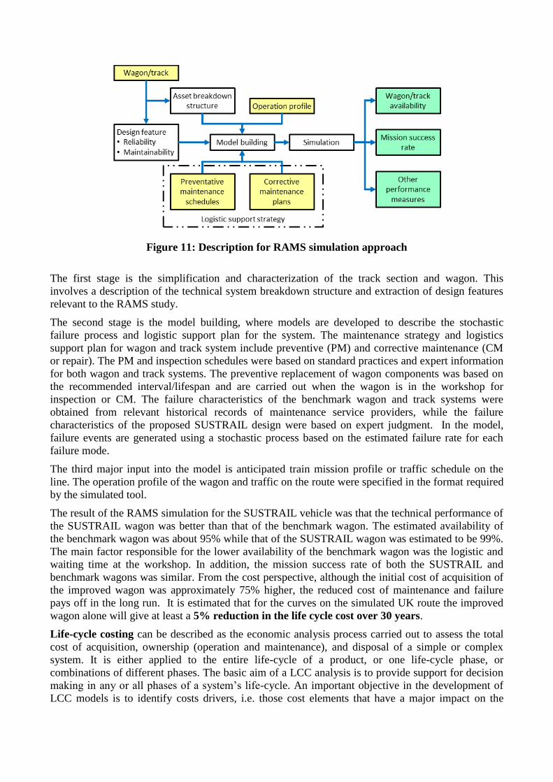
Figure 11: Description for RAMS simulation approach
The first stage is the simplification and characterization of the track section and wagon. This
involves a description of the technical system breakdown structure and extraction of design features
relevant to the RAMS study.
The second stage is the model building, where models are developed to describe the stochastic
failure process and logistic support plan for the system. The maintenance strategy and logistics
support plan for wagon and track system include preventive (PM) and corrective maintenance (CM
or repair). The PM and inspection schedules were based on standard practices and expert information
for both wagon and track systems. The preventive replacement of wagon components was based on
the recommended interval/lifespan and are carried out when the wagon is in the workshop for
inspection or CM. The failure characteristics of the benchmark wagon and track systems were
obtained from relevant historical records of maintenance service providers, while the failure
characteristics of the proposed SUSTRAIL design were based on expert judgment. In the model,
failure events are generated using a stochastic process based on the estimated failure rate for each
failure mode.
The third major input into the model is anticipated train mission profile or traffic schedule on the
line. The operation profile of the wagon and traffic on the route were specified in the format required
by the simulated tool.
The result of the RAMS simulation for the SUSTRAIL vehicle was that the technical performance of
the SUSTRAIL wagon was better than that of the benchmark wagon. The estimated availability of
the benchmark wagon was about 95% while that of the SUSTRAIL wagon was estimated to be 99%.
The main factor responsible for the lower availability of the benchmark wagon was the logistic and
waiting time at the workshop. In addition, the mission success rate of both the SUSTRAIL and
benchmark wagons was similar. From the cost perspective, although the initial cost of acquisition of
the improved wagon was approximately 75% higher, the reduced cost of maintenance and failure
pays off in the long run. It is estimated that for the curves on the simulated UK route the improved
wagon alone will give at least a 5% reduction in the life cycle cost over 30 years.
Life-cycle costing can be described as the economic analysis process carried out to assess the total
cost of acquisition, ownership (operation and maintenance), and disposal of a simple or complex
system. It is either applied to the entire life-cycle of a product, or one life-cycle phase, or
combinations of different phases. The basic aim of a LCC analysis is to provide support for decision
making in any or all phases of a system’s life-cycle. An important objective in the development of
LCC models is to identify costs drivers, i.e. those cost elements that have a major impact on the
LCC. In relation to the SUSTRAIL project, the LCC analysis was carried out to support decisions for
some of the innovations suggested by the project towards a sustainable railway vehicle and track.
For the wagon and track LCC model, all the cost elements were categorised into four aggregate
groups:
Life acquisition cost (investment and renewal for track)
Life operation cost
Life support cost (maintenance cost for track)
Life termination cost
In the cost benefit analysis work the costs were aggregated to the case study route levels. This stage
applies the LCC to the entire route cost structure rather than the partial structure. As an indication of
magnitude, for the UK route, the LCC saving from the track improvement is of the order of 9%
although this route has a relatively high curved track length. If the track uses premium rail steel
together with the improved wagon there would be approximately a 61% reduction in the LCC. In the
‘track improvement with speed change’ scenario, the expert assessment was that the reduction in
LCC would be approximately 43%.
1.3.4.2 Track Access Charges
A key economic interface between infrastructure managers and freight operators is the track access
charge regime: payments by train operators to infrastructure managers for the incremental costs
associated with running the train service. Access charges are the key mechanism by which
infrastructure cost improvements are passed through to freight operators and, in turn, to freight users.
Similarly, suitable discounts in track access charges for different vehicle types can incentivise the
adoption of track friendly vehicles. This is an important incentive given that track friendly vehicles
may imply higher capital costs for operators. To build a financial case for operators to adopt these
vehicles, reductions in on-going costs need to be present and access charges are such a cost (they are
incurred whenever the vehicle is used).
In SUSTRAIL new empirical research has been undertaken to understand how costs (and not just
damage) vary with traffic of different types. The research within SUSTRAIL on access charges has
advanced the understanding of railway infrastructure marginal costs associated with railway traffic
and also researched how implementing price incentives (via differentiated access charges) has
influenced operator behaviour. New work has been undertaken in integrating the two main
approaches (engineering and econometric) to analysing the direct cost to the infrastructure manager
associated with running additional traffic. Further new work has been undertaken to understand
renewals costs and traffic disaggregation in the econometric approach.
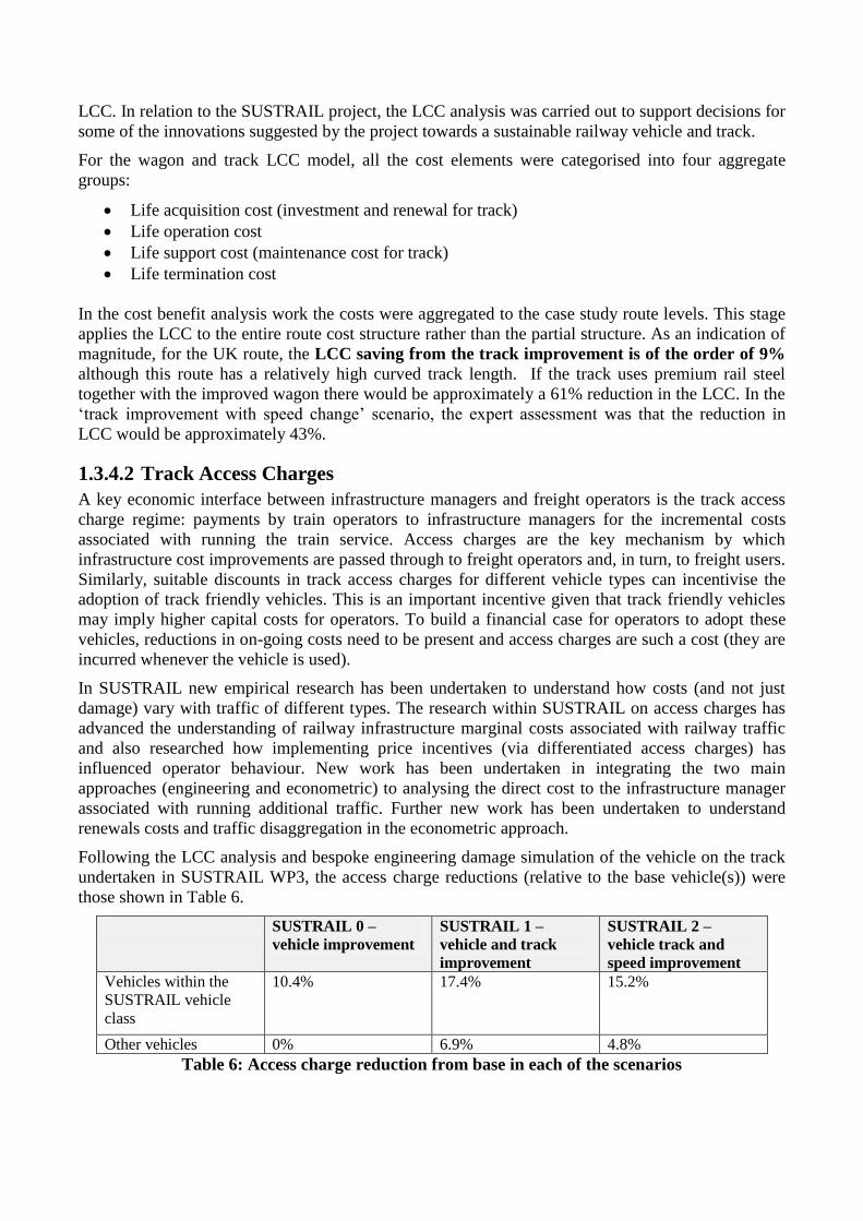
Following the LCC analysis and bespoke engineering damage simulation of the vehicle on the track
undertaken in SUSTRAIL WP3, the access charge reductions (relative to the base vehicle(s)) were
those shown in Table 6.
SUSTRAIL 0 –
vehicle improvement
SUSTRAIL 1 –
vehicle and track
improvement
SUSTRAIL 2 –
vehicle track and
speed improvement
Vehicles within the
SUSTRAIL vehicle
class
10.4% 17.4% 15.2%
Other vehicles 0% 6.9% 4.8%
Table 6: Access charge reduction from base in each of the scenarios
Note that the SUSTRAIL vehicle requires a discount because it does less damage to the track than
the base vehicle.
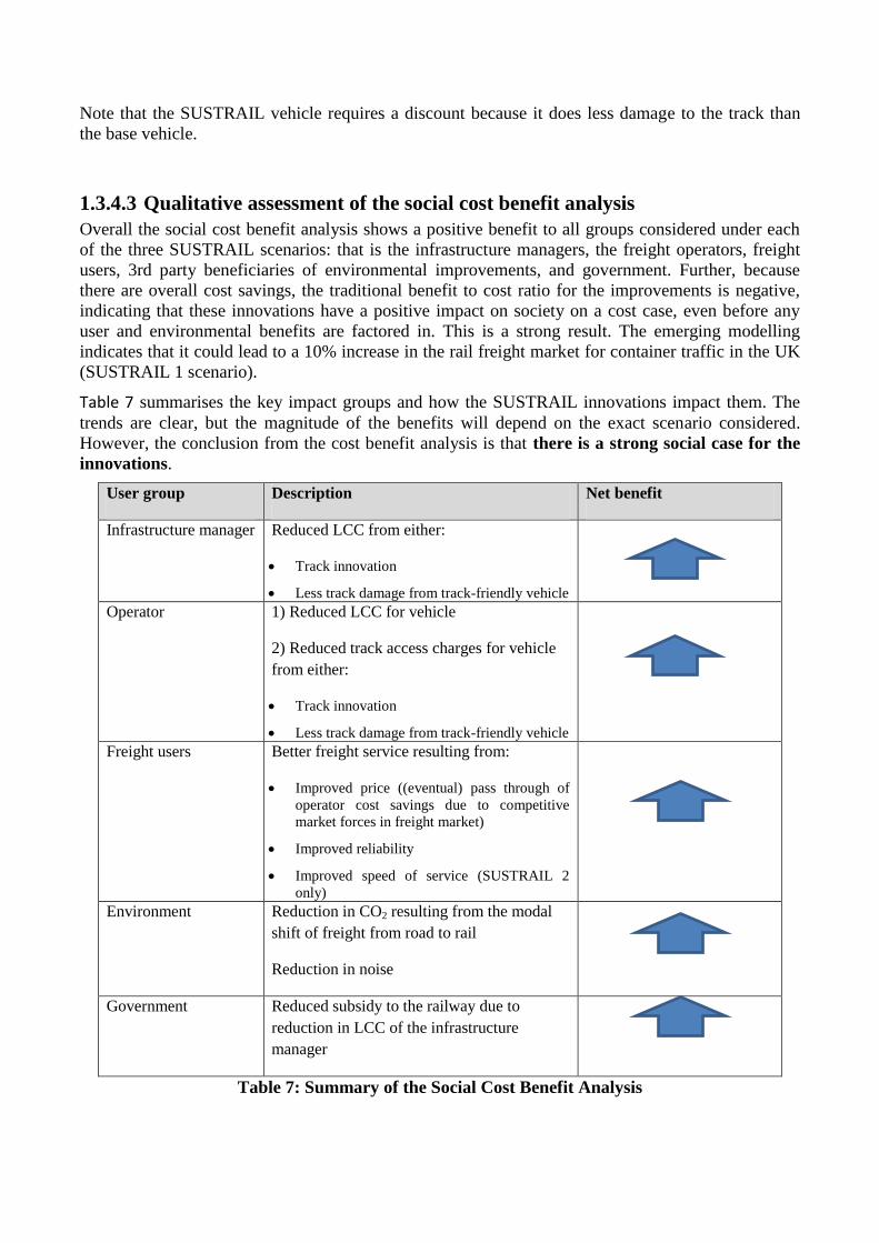
1.3.4.3 Qualitative assessment of the social cost benefit analysis
Overall the social cost benefit analysis shows a positive benefit to all groups considered under each
of the three SUSTRAIL scenarios: that is the infrastructure managers, the freight operators, freight
users, 3rd party beneficiaries of environmental improvements, and government. Further, because
there are overall cost savings, the traditional benefit to cost ratio for the improvements is negative,
indicating that these innovations have a positive impact on society on a cost case, even before any
user and environmental benefits are factored in. This is a strong result. The emerging modelling
indicates that it could lead to a 10% increase in the rail freight market for container traffic in the UK
(SUSTRAIL 1 scenario).
Table 7 summarises the key impact groups and how the SUSTRAIL innovations impact them. The
trends are clear, but the magnitude of the benefits will depend on the exact scenario considered.
However, the conclusion from the cost benefit analysis is that there is a strong social case for the
innovations.
User group Description Net benefit
Infrastructure manager Reduced LCC from either:
Track innovation
Less track damage from track-friendly vehicle
Operator 1) Reduced LCC for vehicle
2) Reduced track access charges for vehicle
from either:
Track innovation
Less track damage from track-friendly vehicle
Freight users Better freight service resulting from:
Improved price ((eventual) pass through of
operator cost savings due to competitive
market forces in freight market)
Improved reliability
Improved speed of service (SUSTRAIL 2
only)
Environment Reduction in CO2 resulting from the modal
shift of freight from road to rail
Reduction in noise
Government Reduced subsidy to the railway due to
reduction in LCC of the infrastructure
manager
Table 7: Summary of the Social Cost Benefit Analysis
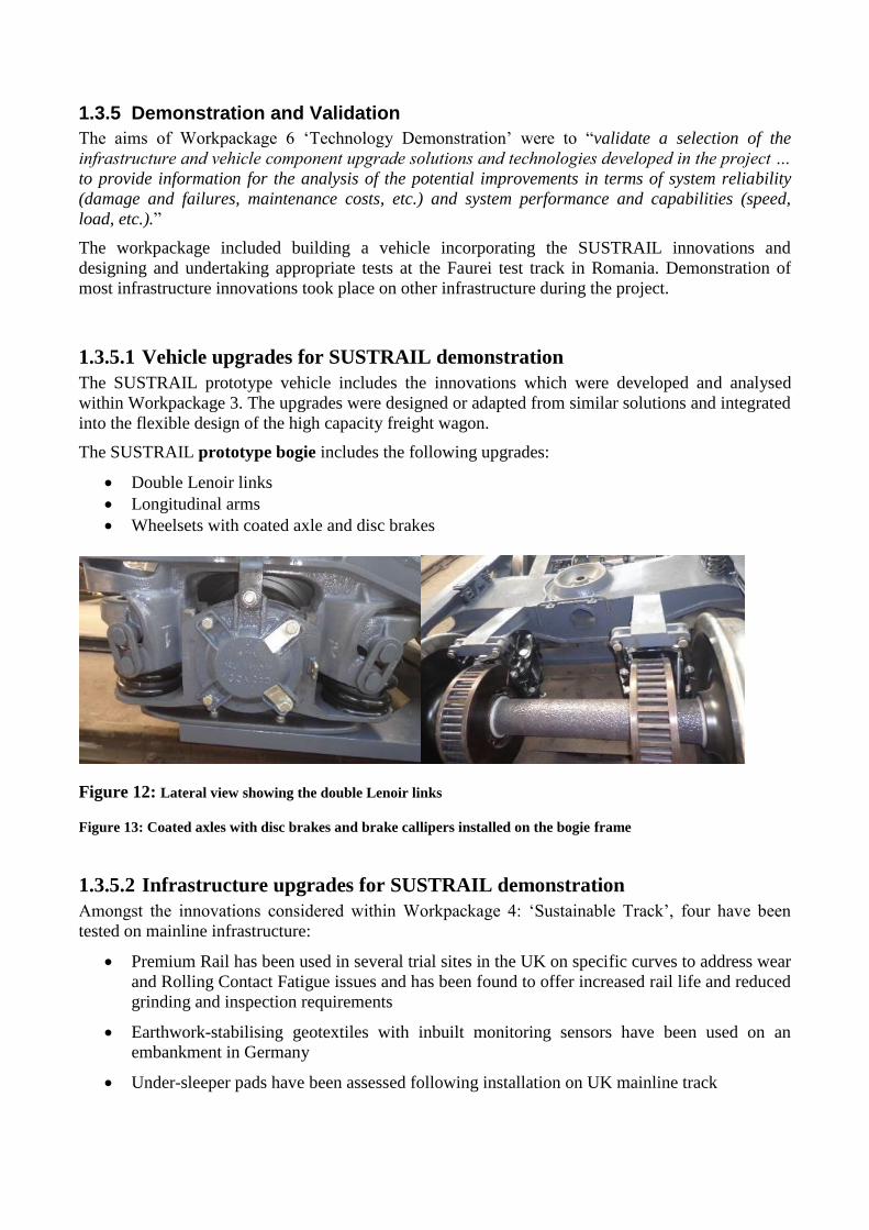
1.3.5 Demonstration and Validation
The aims of Workpackage 6 ‘Technology Demonstration’ were to “validate a selection of the
infrastructure and vehicle component upgrade solutions and technologies developed in the project …
to provide information for the analysis of the potential improvements in terms of system reliability
(damage and failures, maintenance costs, etc.) and system performance and capabilities (speed,
load, etc.).”
The workpackage included building a vehicle incorporating the SUSTRAIL innovations and
designing and undertaking appropriate tests at the Faurei test track in Romania. Demonstration of
most infrastructure innovations took place on other infrastructure during the project.
1.3.5.1 Vehicle upgrades for SUSTRAIL demonstration
The SUSTRAIL prototype vehicle includes the innovations which were developed and analysed
within Workpackage 3. The upgrades were designed or adapted from similar solutions and integrated
into the flexible design of the high capacity freight wagon.
The SUSTRAIL prototype bogie includes the following upgrades:
Double Lenoir links
Longitudinal arms
Wheelsets with coated axle and disc brakes
Figure 12: Lateral view showing the double Lenoir links
Figure 13: Coated axles with disc brakes and brake callipers installed on the bogie frame
1.3.5.2 Infrastructure upgrades for SUSTRAIL demonstration
Amongst the innovations considered within Workpackage 4: ‘Sustainable Track’, four have been
tested on mainline infrastructure:
Premium Rail has been used in several trial sites in the UK on specific curves to address wear
and Rolling Contact Fatigue issues and has been found to offer increased rail life and reduced
grinding and inspection requirements
Earthwork-stabilising geotextiles with inbuilt monitoring sensors have been used on an
embankment in Germany
Under-sleeper pads have been assessed following installation on UK mainline track
Trackside monitoring of vehicles and infrastructure has been undertaken on a line in Sweden
to identify wheel loading and defect issues
Additionally, the rapid application sensor developed by NewRail is to be tested at the test track.
1.3.5.3 Vehicle Laboratory Tests
Dimensional tests
Objective: to verify that the outside dimensions of the vehicle, and any clearances and flexible
connections when completely assembled and in working order, comply with the limits set out in the
standards.
Construction gauge of the wagon test
Objective: to verify that the kinematic envelope of the wagon is in accordance with the design, by the
coefficient of flexibility (sway) test.
The coefficient of flexibility (s) is the relationship between the lateral inclination of the loaded
wagon (η) on its suspension springs as a result of a lateral inclination of the track (δ).
s = tanη/tanδ
Weighing tests
Objective: to verify that the vehicle mass and distribution comply with the limits set out by the
manufacturer and includes tests for the following parameters: the vehicle mass, the measured load
per axle, the measured load per wheel
Friction brake system tests
Objective: to verify that the brake system operates in accordance with the freight wagon design and
give sufficient confidence that the dynamic tests may take place. The following systems shall be
functionally checked statically: emergency brake, service brake, mobility of brake rigging
Parking brake system tests
Objective: to verify that the parking brake system satisfies the requirements of the manufacturer.
The test criteria to demonstrate the effectiveness of the wagon parking brake system involves the
vehicle remaining stationary for a limited period, held by a parking brake subject to leaks (e.g.,
hydraulic or air brake); the brake shall be applied with maximum force and it shall be verified during
a period specified, that there is no significant fall-off in the force applied.
1.3.5.4 Vehicle Field tests
Dynamic structural analysis of the vehicle
The test is to demonstrate the compliance with Wöhler curve of the wagon body.
Braking and braking thermal capacity tests:
A single vehicle “slip brake test” will be performed. The test will be carried out at the following
speeds: 100 km/h, 120 km/h, 140 km/h
The objective of the test is to determine the braked weight percentage, by means of the average
stopping distance.
After each braking test, the thermal capacity of the wheels and brake discs need to be determined.
Evaluation of the running behaviour of the vehicle by measuring accelerations
In these tests running safety, and ride characteristics of the vehicle are evaluated.
Running safety
accelerations at the bogie allow an assessment of running safety on a simplified basis
accelerations in the vehicle body are used for the simplified assessment of running safety
instability of the vehicle is assessed on the basis of a moving RMS value of lateral
accelerations on axles
Ride characteristics
accelerations in the vehicle body are used for assessing ride characteristics of the vehicle; the
assessment includes maximum and RMS values of accelerations
Noise tests
Noise emitted by freight wagons can be either pass-by noise or stationary noise. Stationary noise of a
freight wagon will only be of relevance if the wagon is equipped with auxiliary devices like engines,
generators, or cooling systems, so is not applicable for the SUSTRAIL wagon.
Pass-by noise: the objective of the test is to determine the A-weighted equivalent continuous sound
level.
1.3.5.5 Infrastructure tests
The infrastructure tests were performed to demonstrate that the innovations provide the anticipated
improvements to track resilience or suitable monitoring outputs. The following innovations have
been used trackside in the UK, Sweden and Germany to validate their performance and therefore
have not been included in the trials to be undertaken at the AFER Railway Testing Centre Faurei,
Romania.
Testing of Premium Rail
HP335 has been intensively monitored at eight trial sites across the United Kingdom. Seven of those
sites were in Network Rail Infrastructure, and one on a light rail system. All trial sites were chosen
by the customer based on their previous degradation history and have been monitored in
collaboration with the customer at regular intervals for up to four years for wear, rolling contact
fatigue, corrugation, and weld performance. All trial sites have seen positive results compared to
previous standard grade rails. Following these trials the grade was fully approved for use on Network
Rail infrastructure and as of March 2015 over 600 km of HP335 rail has been supplied for
installation within the United Kingdom. HP335 is designed to be used on curved track and other high
duty areas where rolling contact fatigue and wear are the relevant degradation mechanisms.
Rapid application sensors as a tool for infrastructure managers for track condition
monitoring and assessment
A compact and portable rapid application sensor system has been developed by partner NewRail to
utilise advances in micro-processing, wireless and battery technologies to develop a system which
can be applied rapidly. This allows the system to be installed between service trains and deployed
almost anywhere on the network. The ability of the system to be rapidly installed without disrupting
service trains and its independence from the power infrastructure make it an effective tool not only
for collecting data on new track constructions or for model validation, but also as a site investigation
tool to assess the performance of track and assist in identifying and resolving issues on sites were
problems have been identified. The prototype system comprises a combination accelerometer,
gyroscope, and magnetometer sensor stick, which measures each of these parameters in three axis,
connected to a processor with storage memory programed to record the output from the sensor. In
addition to these components there is a small battery pack to power the system and a wireless
connection module to allow the system to be set up, measurements to be initiated and stopped, and
the data downloaded without the operator being at immediate risk from passing vehicles. The system
could be adapted to measure other parameters by substituting different sensors and re-programming
the system.
Sensor-integrated geotextile system
Sensor-integrated geotextiles have been developed by partner D’Appolonia and have been
considered within SUSTRAIL as a way of performing Structural Health Monitoring (SHM) of the
railway infrastructure. In addition to the usual functions geotextiles perform (strengthening,
filtration, stabilisation, separation, drainage) these geotextiles can undertake SHM as the result of the
integration within the structure of distributed fibre-optic sensors. An efficient signal processing
technique is used to process the raw sensor measurements to estimate damage size and location.
The benefits of using sensor-integrated geotextiles within the railway substructure include: Indicate
impending failure, Evaluate critical design assumptions, Assess contractor’s means and methods , so
control construction, Minimize damage to adjacent structures, Provide data to help select remedial
methods to fix problems, Document performance for assessing damages, Inform stakeholders,
Satisfy regulators, Reduce litigation, Advance state-of-knowledge.
A field test was performed near Chemnitz (Germany), on a route having a very high traffic volume.
The portion of the embankment was more than 100 years old and has been selected since it was
under reconstruction. Periodic measurements have been carried out in order to detect any movement
within the embankment and its evolution during time.
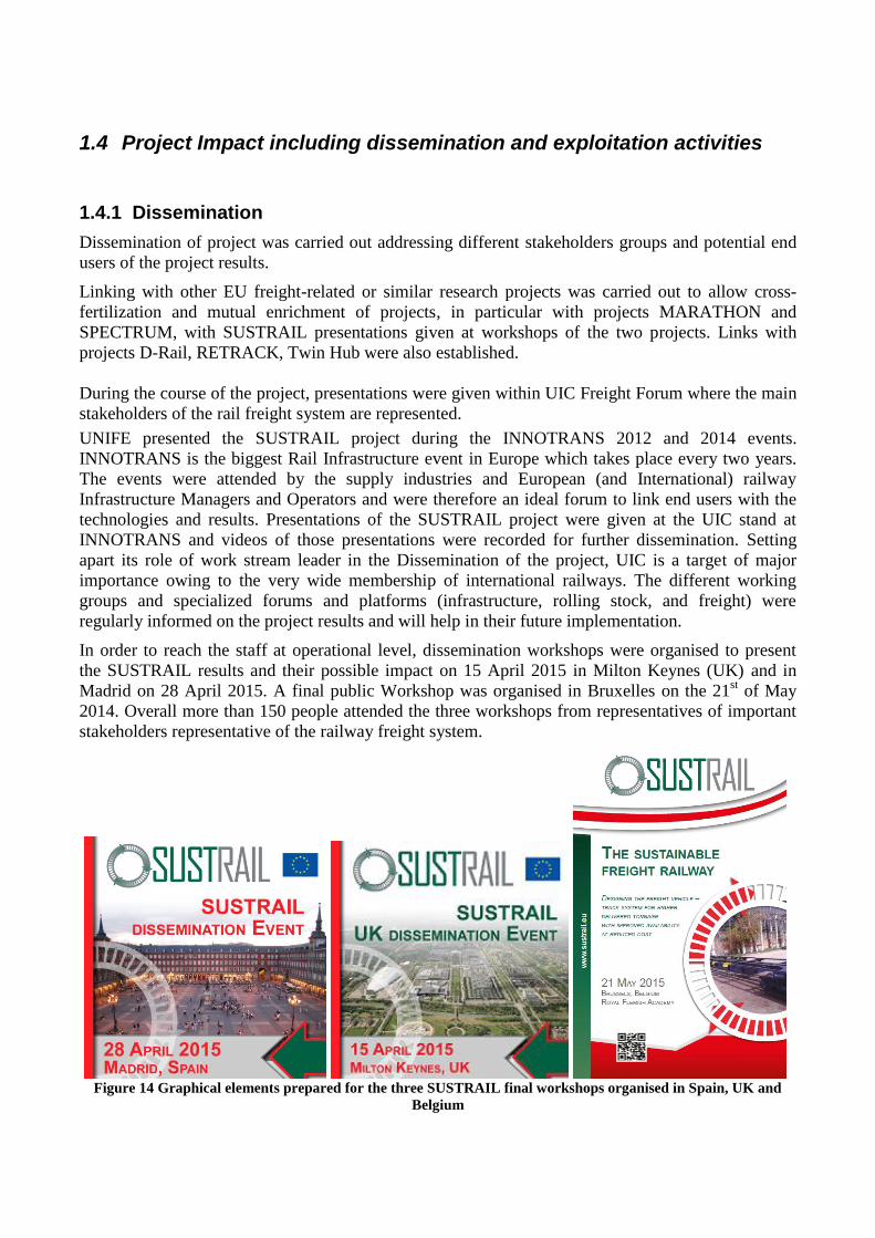
1.4 Project Impact including dissemination and exploitation activities
1.4.1 Dissemination
Dissemination of project was carried out addressing different stakeholders groups and potential end
users of the project results.
Linking with other EU freight-related or similar research projects was carried out to allow cross-
fertilization and mutual enrichment of projects, in particular with projects MARATHON and
SPECTRUM, with SUSTRAIL presentations given at workshops of the two projects. Links with
projects D-Rail, RETRACK, Twin Hub were also established.
During the course of the project, presentations were given within UIC Freight Forum where the main
stakeholders of the rail freight system are represented.
UNIFE presented the SUSTRAIL project during the INNOTRANS 2012 and 2014 events.
INNOTRANS is the biggest Rail Infrastructure event in Europe which takes place every two years.
The events were attended by the supply industries and European (and International) railway
Infrastructure Managers and Operators and were therefore an ideal forum to link end users with the
technologies and results. Presentations of the SUSTRAIL project were given at the UIC stand at
INNOTRANS and videos of those presentations were recorded for further dissemination. Setting
apart its role of work stream leader in the Dissemination of the project, UIC is a target of major
importance owing to the very wide membership of international railways. The different working
groups and specialized forums and platforms (infrastructure, rolling stock, and freight) were
regularly informed on the project results and will help in their future implementation.
In order to reach the staff at operational level, dissemination workshops were organised to present
the SUSTRAIL results and their possible impact on 15 April 2015 in Milton Keynes (UK) and in
Madrid on 28 April 2015. A final public Workshop was organised in Bruxelles on the 21st of May
2014. Overall more than 150 people attended the three workshops from representatives of important
stakeholders representative of the railway freight system.
Figure 14 Graphical elements prepared for the three SUSTRAIL final workshops organised in Spain, UK and
Belgium
UNIFE is a European association that represents the interests of the railway supply industry in
Europe at the level of both European and international institutions. Its membership comprises
manufacturers and integrators of railway rolling stock, subsystems, components, signalling
equipment and infrastructure. UNIFE participated actively in dissemination, exploitation and training
activities. Its particular focus was dissemination and exploitation where, through its committees,
technical forums, and events it provided input from and result access to the rail industries, including
maintenance contractors and suppliers. Further, it will continue distributing SUSTRAIL material at
its annual and joint research events throughout the year. UNIFE is in close association with the
national industry associations also a point of dissemination to the industries outside of the project.
1.4.2 Dissemination Media
1.4.2.1 Project deliverables
SUSTRAIL generated around 39 deliverable reports exclusively distributed to the European
Commission and to the Partners of the Consortium. About 35 of these deliverables are technical
reports and present the results of the project. Many of those deliverables have a public status for
dissemination: some deliverables have been changed from status “Confidential” to “Public” as
agreed during one of the meeting of the General Assembly, in order to increase the visibility of the
project results and reach the interested stakeholders. Public deliverables are available from the
SUSTRAIL web page.
1.4.2.2 Concluding technical report
Through the grant agreement with the European Commission, SUSTRAIL is committed to
disseminating the project results. Therefore the Concluding Technical Report (CTR) has been drafted
so as to be most complete document on the results of the project and on the methods used, the way
the results are to be implemented, the identified technical problems and the proposed solutions.
Available as hard copies as well as on the public website, it will be the “key” for reaching and using
the SUSTRAIL results and it will summarize the content of all the project technical deliverables.
1.4.2.3 Top Management Summary report
Designed to be delivered via UIC Forums and Platforms and UNIFE high level committees to the top
management (Infrastructure, Freight, Asset Management and Industry), this document based on the
executive summary of the CTR will explain what SUSTRAIL has achieved and which effects can be
expected – also in terms of costs – from the implementation of these results.
1.4.2.4 Flyers
A project flyer has been produced at the beginning of the project, where the list of partners, the
project objectives, the structure, the targeted innovation and expected benefits are presented.
The updated project flyer has been produced at the end of the project. It gives a visual and quick
overview of the results and their benefits. The purpose of flyers is to draw attention to the project
results and refer interested parties to the more comprehensive documents: Concluding Technical
Report, Top Management Report, Guidelines and Deliverables. Flyers were distributed not only at
the main project meetings, but also on each occasion the project was presented to the interested
audience: seminars, workshops, conferences, exhibitions (TRA 2014, Innotrans 2012 and 2014).
Figure 15 The updated SUSTRAIL flyer as distributed at the Final Conference on 21 May 2015
1.4.2.5 Newsletters, press release
The Sustrail Newsletter was published on an annual basis in 2011, 2012, 2013, and 2015.
Newsletters have been sent to all project members and made available online on the SUSTRAIL
Public website. News on the project were also fed into the electronic newsletters of UIC and UNIFE.
Figure 16 : Sustrail E-Newsletter
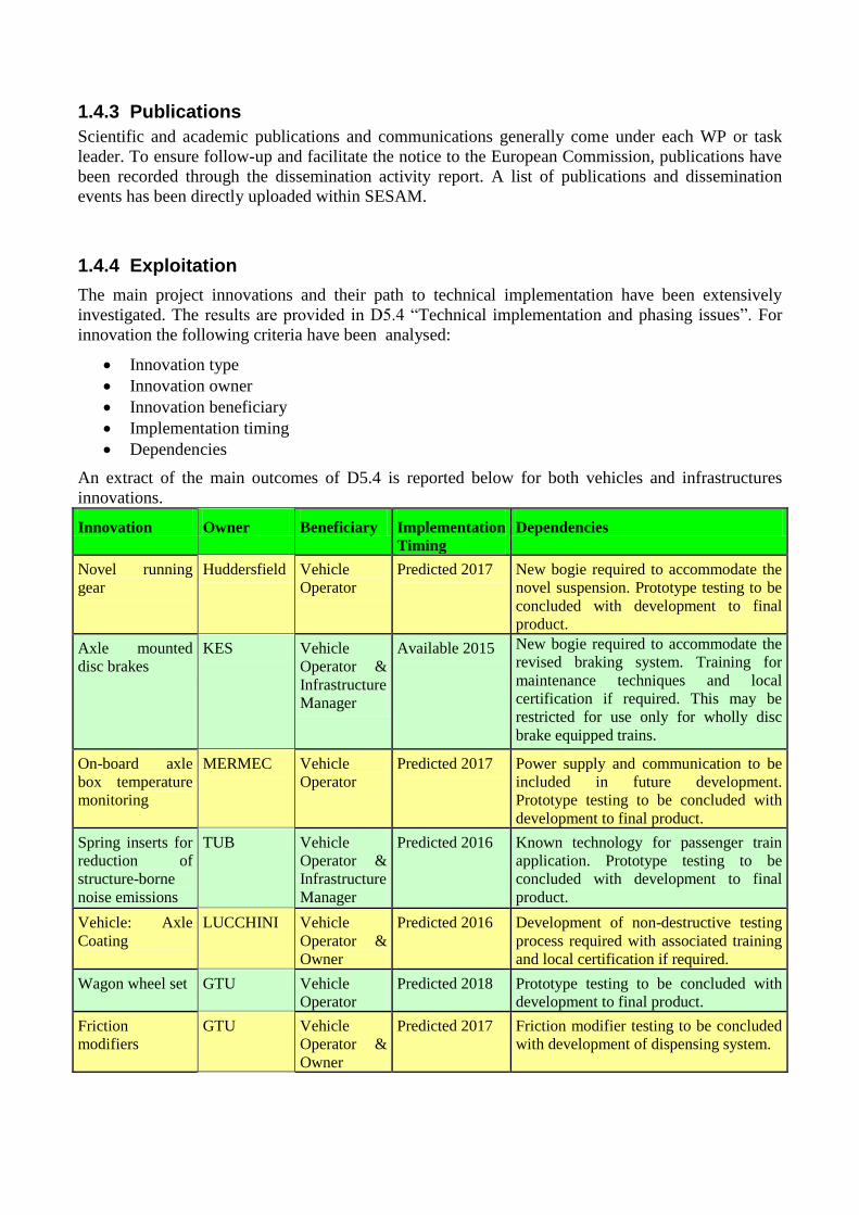
1.4.3 Publications
Scientific and academic publications and communications generally come under each WP or task
leader. To ensure follow-up and facilitate the notice to the European Commission, publications have
been recorded through the dissemination activity report. A list of publications and dissemination
events has been directly uploaded within SESAM.
1.4.4 Exploitation
The main project innovations and their path to technical implementation have been extensively
investigated. The results are provided in D5.4 “Technical implementation and phasing issues”. For
innovation the following criteria have been analysed:
Innovation type
Innovation owner
Innovation beneficiary
Implementation timing
Dependencies
An extract of the main outcomes of D5.4 is reported below for both vehicles and infrastructures
innovations.
Innovation Owner Beneficiary Implementation
Timing
Dependencies
Novel running
gear
Huddersfield Vehicle
Operator
Predicted 2017 New bogie required to accommodate the
novel suspension. Prototype testing to be
concluded with development to final
product.
Axle mounted
disc brakes
KES Vehicle
Operator &
Infrastructure
Manager
Available 2015 New bogie required to accommodate the
revised braking system. Training for
maintenance techniques and local
certification if required. This may be
restricted for use only for wholly disc
brake equipped trains.
On-board axle
box temperature
monitoring
MERMEC Vehicle
Operator
Predicted 2017 Power supply and communication to be
included in future development.
Prototype testing to be concluded with
development to final product.
Spring inserts for
reduction of
structure-borne
noise emissions
TUB Vehicle
Operator &
Infrastructure
Manager
Predicted 2016 Known technology for passenger train
application. Prototype testing to be
concluded with development to final
product.
Vehicle: Axle
Coating
LUCCHINI Vehicle
Operator &
Owner
Predicted 2016 Development of non-destructive testing
process required with associated training
and local certification if required.
Wagon wheel set GTU Vehicle
Operator
Predicted 2018 Prototype testing to be concluded with
development to final product.
Friction
modifiers
GTU Vehicle
Operator &
Owner
Predicted 2017 Friction modifier testing to be concluded
with development of dispensing system.
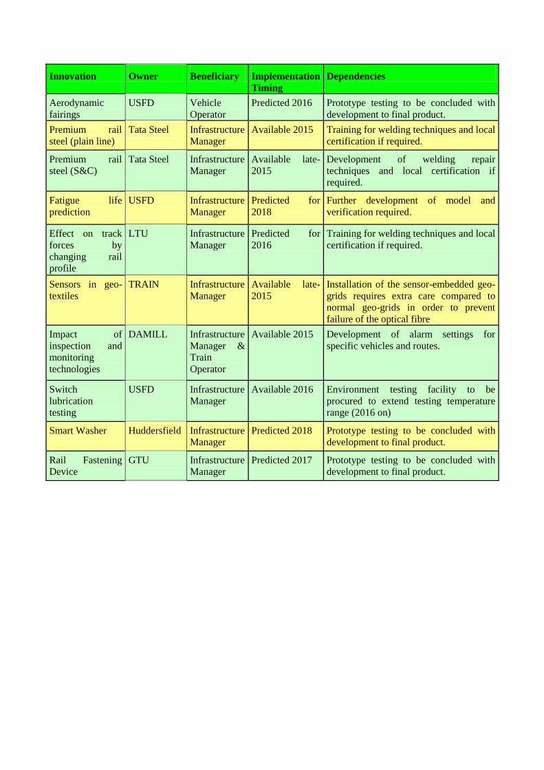
Innovation Owner Beneficiary Implementation
Timing
Dependencies
Aerodynamic
fairings
USFD Vehicle
Operator
Predicted 2016 Prototype testing to be concluded with
development to final product.
Premium rail
steel (plain line)
Tata Steel Infrastructure
Manager
Available 2015 Training for welding techniques and local
certification if required.
Premium rail
steel (S&C)
Tata Steel Infrastructure
Manager
Available late-
2015
Development of welding repair
techniques and local certification if
required.
Fatigue life
prediction
USFD Infrastructure
Manager
Predicted for
2018
Further development of model and
verification required.
Effect on track
forces by
changing rail
profile
LTU Infrastructure
Manager
Predicted for
2016
Training for welding techniques and local
certification if required.
Sensors in geo-
textiles
TRAIN Infrastructure
Manager
Available late-
2015
Installation of the sensor-embedded geo-
grids requires extra care compared to
normal geo-grids in order to prevent
failure of the optical fibre
Impact of
inspection and
monitoring
technologies
DAMILL Infrastructure
Manager &
Train
Operator
Available 2015 Development of alarm settings for
specific vehicles and routes.
Switch
lubrication
testing
USFD Infrastructure
Manager
Available 2016 Environment testing facility to be
procured to extend testing temperature
range (2016 on)
Smart Washer Huddersfield Infrastructure
Manager
Predicted 2018 Prototype testing to be concluded with
development to final product.
Rail Fastening
Device
GTU Infrastructure
Manager
Predicted 2017 Prototype testing to be concluded with
development to final product.
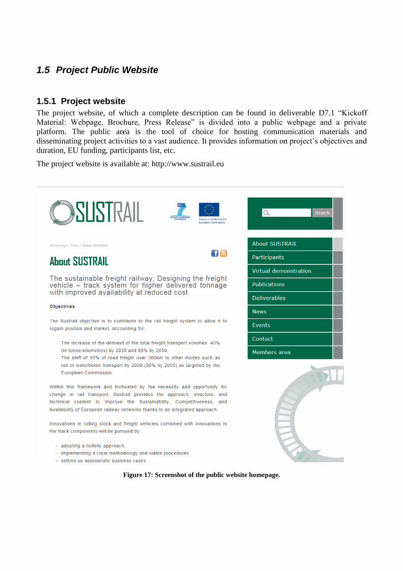
1.5 Project Public Website
1.5.1 Project website
The project website, of which a complete description can be found in deliverable D7.1 “Kickoff
Material: Webpage, Brochure, Press Release” is divided into a public webpage and a private
platform. The public area is the tool of choice for hosting communication materials and
disseminating project activities to a vast audience. It provides information on project’s objectives and
duration, EU funding, participants list, etc.
The project website is available at: http://www.sustrail.eu
Figure 17: Screenshot of the public website homepage.
In the end, the public website now contains 9 public pages:
About SUSTRAIL
Participants
Virtual demonstration
Publications
Deliverables
News
Events
Contact
Members area
The sections Virtual demonstration, Publications, Deliverables, News, Events have been added to
host and facilitate public access to dissemination and information documents. The private area is
accessible from the public webpage by clicking the link “Members Area” on the page menu or at
(http://ovidentia.uic.org).
This tool is the platform where documents and information of any type can be uploaded and made
available by and for the project partners.
Access to the Members Area is restricted to the Consortium members only, with access rights
depending on their role and implication level. After 48 of activity, 103 persons have received various
access rights to the SUSTRAIL private area.
2 Use and dissemination of foreground Additional Scientific Publication not inserted on SESAM (D.O.I. not recognized by the D.O.I.
database) are provided in the table below
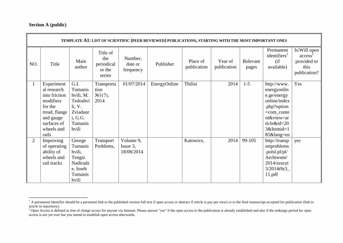
Section A (public)
TEMPLATE A1: LIST OF SCIENTIFIC (PEER REVIEWED) PUBLICATIONS, STARTING WITH THE MOST IMPORTANT ONES
NO. Title Main
author
Title of
the
periodical
or the
series
Number,
date or
frequency
Publisher Place of
publication
Year of
publication
Relevant
pages
Permanent
identifiers1
(if
available)
Is/Will open
access2
provided to
this
publication?
1 Experiment
al research
into friction
modifiers
for the
tread, flange
and gauge
surfaces of
wheels and
rails
G.I.
Tumanis
hvili, M.
Tedoshvi
li, V.
Zviadaur
i, G.G.
Tumanis
hvili
Transporta
tion
№1(7),
2014
01/07/2014 EnergyOnline Tbilisi 2014 1-5 http://www.
energyonlin
e.ge/energy
online/index
.php?option
=com_conte
nt&view=ar
ticle&id=20
3&Itemid=1
85&lang=en
Yes
2 Improving
of operating
ability of
wheels and
rail tracks
George
Tumanis
hvili,
Tengiz
Nadiradz
e, Ioseb
Tumanis
hvili
Transport
Problems,
Volume 9,
Issue 3,
18/08/2014
Katowice, 2014 99-105 http://transp
ortproblems
.polsl.pl/pl/
Archiwum/
2014/zeszyt
3/2014t9z3_
11.pdf
yes
1 A permanent identifier should be a persistent link to the published version full text if open access or abstract if article is pay per view) or to the final manuscript accepted for publication (link to
article in repository). 2 Open Access is defined as free of charge access for anyone via Internet. Please answer "yes" if the open access to the publication is already established and also if the embargo period for open
access is not yet over but you intend to establish open access afterwards.