1 Fair Queuing Memory Systems Kyle Nesbit, Nidhi Aggarwal, Jim Laudon *, and Jim Smith University of...
38
1 Fair Queuing Memory Systems Kyle Nesbit, Nidhi Aggarwal, Jim Laudon*, and Jim Smith University of Wisconsin – Madison Department of Electrical and Computer Engineering Sun Microsystems*
-
Upload
buddy-rich -
Category
Documents
-
view
215 -
download
2
Transcript of 1 Fair Queuing Memory Systems Kyle Nesbit, Nidhi Aggarwal, Jim Laudon *, and Jim Smith University of...

1
Fair Queuing Memory Systems
Kyle Nesbit, Nidhi Aggarwal, Jim Laudon*, and Jim Smith
University of Wisconsin – MadisonDepartment of Electrical and Computer Engineering
Sun Microsystems*
2
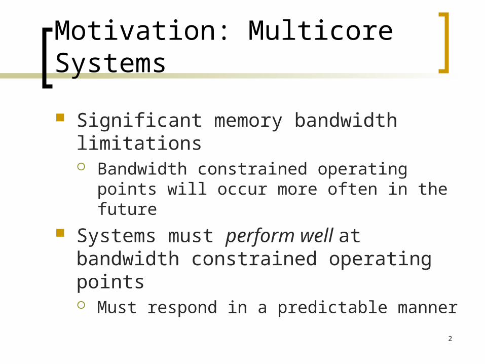
Motivation: Multicore Systems
Significant memory bandwidth limitations Bandwidth constrained operating points
will occur more often in the future Systems must perform well at
bandwidth constrained operating points Must respond in a predictable manner

3
Bandwidth Interference
Desktops Soft real-time
constraints Servers
Fair sharing / billing
Decreases overall throughput
IPC
0
0.2
0.40.6
0.8
1
vpr vprwith
crafty
vprwithart
4
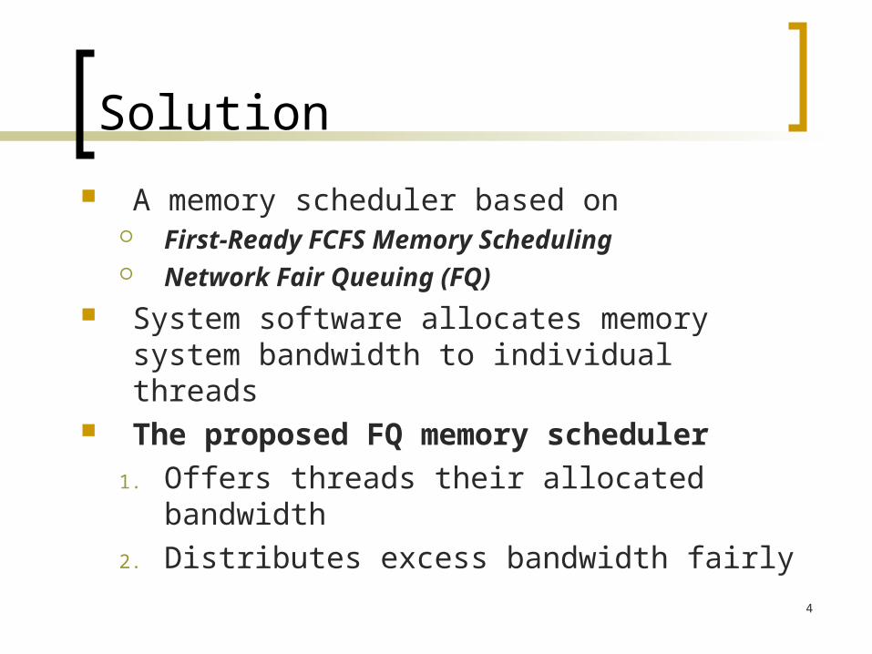
Solution
A memory scheduler based on First-Ready FCFS Memory Scheduling Network Fair Queuing (FQ)
System software allocates memory system bandwidth to individual threads
The proposed FQ memory scheduler
1. Offers threads their allocated bandwidth
2. Distributes excess bandwidth fairly

5
Background
Memory Basics Memory Controllers First-Ready FCFS Memory Scheduling Network Fair Queuing

6
BackgroundMemory Basics
7
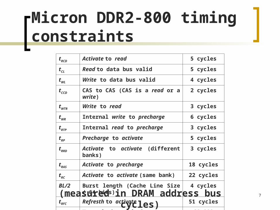
Micron DDR2-800 timing constraints
(measured in DRAM address bus cycles)
tRCD Activate to read 5 cycles
tCL Read to data bus valid 5 cycles
tWL Write to data bus valid 4 cycles
tCCD CAS to CAS (CAS is a read or a write) 2 cycles
tWTR Write to read 3 cycles
tWR Internal write to precharge 6 cycles
tRTP Internal read to precharge 3 cycles
tRP Precharge to activate 5 cycles
tRRD Activate to activate (different banks) 3 cycles
tRAS Activate to precharge 18 cycles
tRC Activate to activate (same bank) 22 cycles
BL/2 Burst length (Cache Line Size / 64 bits)
4 cycles
tRFC Refresth to activate 51 cycles
tRFC Max refresh to refresh 28,000 cycles

8
Background:Memory Controller
Memory Controller
L2 Cache
ProcessorL1 Caches
L2 Cache
ProcessorL1 Caches
ChipBoundarySDRAM
CMP
9
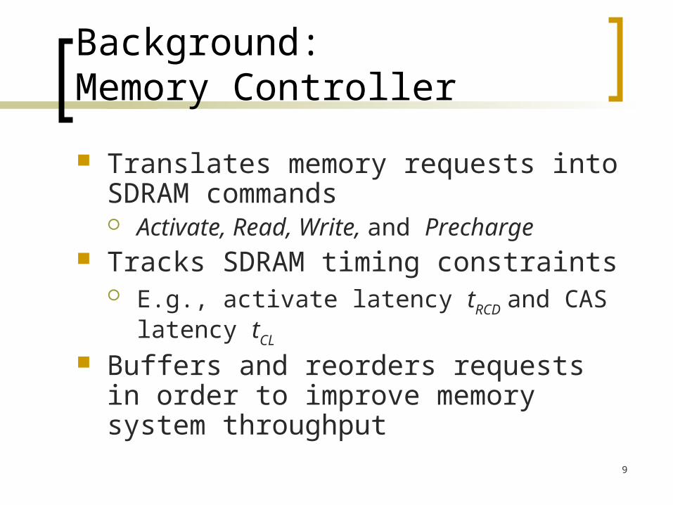
Background:Memory Controller
Translates memory requests into SDRAM commands Activate, Read, Write, and Precharge
Tracks SDRAM timing constraints E.g., activate latency tRCD and CAS
latency tCL
Buffers and reorders requests in order to improve memory system throughput

10
Background:Memory Scheduler
…Bank 1Requests
Bank nRequests
Cache LineWrite Buffer
Cache LineRead Buffer
TransactionBuffer
Arrival Time Assignment
Processor Data Bus Processor Data Bus
SDRAM Data Bus SDRAM Data BusSDRAM Address Bus
MemoryRequests
Control PathData Path Request / Command Path
FR-FCFS Scheduler

11
Background:FR-FCFS Memory Scheduler
A First-Ready FCFS priority queues1. Ready commands2. CAS commands over RAS commands3. earliest arrival time
Ready with respect to the SDRAM timing constraints
FR-FCFS is a good general-purpose scheduling policy [Rixner 2004]
Multithreaded issues

12
Example: Two Threads
a1a2a3a4
Thread 1
a1
Bursty MLP, bandwidth constrained
Thread 2
Isolated misses, latency sensitive
a5a6a7a8
ComputationMemory Latency
a2 a3 a4 a5
Computation

13
First Come First Serve
a1a2a3a4Thread 1
SharedMemorySystem
Thread 2 a2a1
a5a6a7a8

14
Background:Network Fair Queuing
Network Fair Queuing (FQ) provides QoS in communication networks
Network flows are allocated bandwidth on each network link along the flow’s path
Routers use FQ algorithms to offer flows their allocated bandwidth
Minimum bandwidth bounds end-to-end communication delay through the network
We leverage FQ theory to provide QoS in memory systems
15
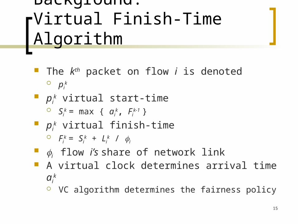
Background:Virtual Finish-Time Algorithm
The kth packet on flow i is denoted pi
k
pik virtual start-time
Sik = max { ai
k, Fik-1 }
pik virtual finish-time
Fik = Si
k + Lik / i
i flow i’s share of network link A virtual clock determines arrival time ai
k
VC algorithm determines the fairness policy

16
Quality of Service
Each thread is allocated a fraction i of the memory system bandwidth
Desktop – soft real time applications Server – differentiated service – billing
The proposed FQ memory scheduler1. Offers threads their allocated bandwidth,
regardless of the load on the memory system
2. Distributes excess bandwidth according to the FQ memory scheduler’s fairness policy

17
Quality of Service
Minimum Bandwidth ⇒ QoS A thread allocated a fraction i of the
memory system bandwidth will perform as well as the same thread on a private memory system operating at i of the frequency

18
Fair Queuing Memory Scheduler
VTMS is used to calculate memory request deadlines Request deadlines are
virtual finish-times FQ scheduler selects
1. the first-ready pending request
2. with the earliest deadline first (EDF)
FQ Scheduler
TransactionBuffer
SDRAM
Thread 1VTMS
Thread mVTMS
…
Deadline / Finish-TimeAlgorithm
…Thread 1Requests
Thread mRequests

19
a5a6a7a8
Fair Queuing Memory Scheduler
a2a3a4a1Thread 1
SharedMemorySystem
Thread 2
Dilated by the reciprocal i Memory latency
Virtual Time
Virtual Time
Deadlines
a1 a2 a3 a4
Deadlines
20
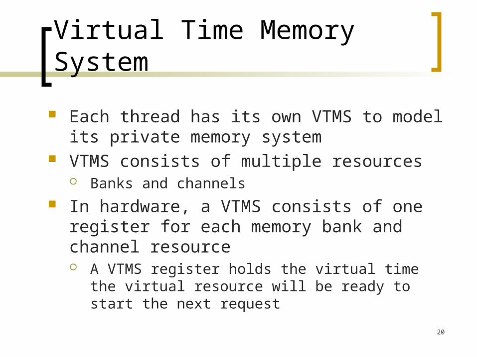
Virtual Time Memory System
Each thread has its own VTMS to model its private memory system
VTMS consists of multiple resources Banks and channels
In hardware, a VTMS consists of one register for each memory bank and channel resource A VTMS register holds the virtual time the virtual
resource will be ready to start the next request

21
Virtual Time Memory System
A request’s deadline is its virtual finish-time The time the request would finish if the request’s
thread were running on a private memory system operating at i of the frequency
A VTMS model captures fundamental SDRAM timing characteristics Abstracts away some details in order to apply
network FQ theory

22
Priority Inversion
First-ready scheduling is required to improve bandwidth utilization
Low priority ready commands can block higher priority (earlier virtual finish-time) commands
Most priority inversion blocking occurs at active banks, e.g. a sequence of row hits
23
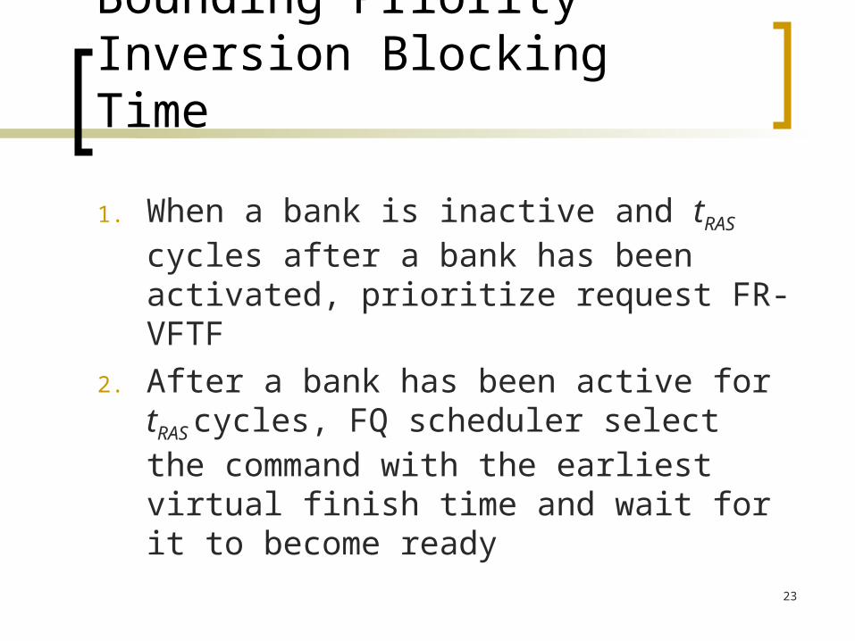
Bounding Priority Inversion Blocking Time
1. When a bank is inactive and tRAS cycles after a bank has been activated, prioritize request FR-VFTF
2. After a bank has been active for tRAS
cycles, FQ scheduler select the command with the earliest virtual finish time and wait for it to become ready
24
Evaluation
Simulator originally developed at IBM Research
Structural model Adopts the ASIM modeling methodology Detailed model of finite memory system
resources Simulate 20 statistically representative
100M instruction SPEC2000 traces
25
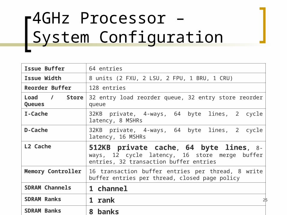
4GHz Processor – System Configuration
Issue Buffer 64 entries
Issue Width 8 units (2 FXU, 2 LSU, 2 FPU, 1 BRU, 1 CRU)
Reorder Buffer 128 entries
Load / Store Queues 32 entry load reorder queue, 32 entry store reorder queue
I-Cache 32KB private, 4-ways, 64 byte lines, 2 cycle latency, 8 MSHRs
D-Cache 32KB private, 4-ways, 64 byte lines, 2 cycle latency, 16 MSHRs
L2 Cache 512KB private cache, 64 byte lines, 8-ways, 12 cycle latency, 16 store merge buffer entries, 32 transaction buffer entries
Memory Controller 16 transaction buffer entries per thread, 8 write buffer entries per thread, closed page policy
SDRAM Channels 1 channelSDRAM Ranks 1 rankSDRAM Banks 8 banks

26
Evaluation
We use data bus utilization to roughly approximate “aggressiveness”
Single Thread Data Bus Utilization
0%
20%
40%
60%
80%
100%
art
equa
ke
mcf
face
rec
luca
s
gcc
swim
mgrid
apsi
wup
wise
two
lf
gap
amm
p
bzip2
gzip
vpr
mesa
sixtrack
perlb
mk
craftyU
tiliz
atio
n

27
Evaluation
We present results for a two thread workload that stresses the memory system Construct 19 workloads by combining each
benchmark (subject thread) with art, the most aggressive benchmark (background thread)
Static partitioning of memory bandwidth i = .5 IPC normalized to QoS IPC
Benchmark’s IPC on private memory system at i = .5 the frequency (.5 the bandwidth)
More results in the paper

28
Normalized IPC of Subject Thread
0
0.5
1
1.5
equake
mcf
facerec
lucas
gcc
swim
mgrid
apsi
wupw
ise
twolf
gap
amm
p
bzip2
gzip
vpr
mesa
sixtrack
perlbmk
crafty
hmean
No
rmal
ized
IP
C
Normalized IPC of Background Thread (art)
0
0.5
1
1.5
2
equake
mcf
facerec
lucas
gcc
swim
mgrid
apsi
wupw
ise
twolf
gap
amm
p
bzip2
gzip
vpr
mesa
sixtrack
perlbmk
crafty
hmean
No
rmal
ized
IP
C
FR-FCFS FQ

29
Subject Thread of Two Thread Workload (Background Thread is art)
Throughput – Harmonic Mean of Normalized IPCs
0
0.2
0.4
0.6
0.8
1
1.2
1.4
equake
mcf
facerec
lucas
gcc
swim
mgrid
apsi
wupw
ise
twolf
gap
amm
p
bzip2
gzip
vpr
mesa
sixtrack
perlbmk
crafty
hmean
Har
mo
nic
Mea
n o
f N
orm
aliz
ed I
PC
s
FR-FCFS FQ

30

31
Summary and Conclusions
Existing techniques can lead to unfair sharing of memory bandwidth resources⇒ Destructive interference
Fair queuing is a good technique to provide QoS in memory systems
Providing threads QoS eliminates destructive interference which can significantly improve system throughput

32
Backup Slides

33
Generalized Processor Sharing
Ideal generalized processor sharing (GPS) Each flow i is allocated a
share i of the shared network link
GPS server services all backlogged flows simultaneously in proportion to their allocated shares
Flow 1 Flow 2 Flow 3 Flow 4
1 2 3 4

34
Background:Network Fair Queuing
Network FQ algorithms model each flow as if it were on a private link Flow i’s private link has i the bandwidth
of the real link Calculates packet deadlines
A packet’s deadline is the virtual time the packet finishes its transmission on its private link

35
Virtual Time Memory System Finish Time Algorithm
Thread i’s kth memory request is denoted mi
k
mik bank j virtual start-time
Bj.Sik = max { ai
k , Bj.Fi(k-1)’ }
mik bank j virtual finish-time
Bj.Fik = Bj.Si
k + Bj.Lik / i
mik channel virtual start-time
C.Sik = max { Bj.Fi
k-1, C.Fik-1}
mik channel virtual finish-time
C.Fik = C.Si
k + C.Lik / i

36
Fairness Policy
FQMS Fairness policy: distribute excess bandwidth to the thread that has consumed the least excess bandwidth (relative to its service share) in the past Different than the fairness policy commonly used
in networks Differs from the fairness policy commonly
used in networks because a memory system is an integral part of a closed system

37
Background:SDRAM Memory Systems
SDRAM 3D Structure Banks Rows Columns
SDRAM Commands Activate row Read or write columns Precharge bank

38
Virtual Time Memory SystemService Requirements
SDRAM Command Bcmd .L Ccmd .L
Activate tRCD n/a
Read tCL BL/2
Write tWL BL/2
Precharge tRP + (tRAS - tRCD - tCL) n/a
The tRAS timing constraint overlaps read and write bank
timing constraints Precharge bank service requirement accounts for the
overlap