1 Electrical Circuits 2 Basic Electric Circuit: In a circuit, the electrons are flowing or moving....
43
1 Electrical Circuits
-
Upload
randolf-phillips -
Category
Documents
-
view
214 -
download
0
Transcript of 1 Electrical Circuits 2 Basic Electric Circuit: In a circuit, the electrons are flowing or moving....

1
Electrical Circuits

2
Basic Electric Circuit:
In a circuit, the electrons are flowing or moving. They are not stationary or static.
3
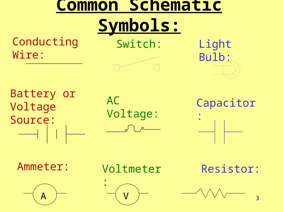
Common Schematic Symbols:
Conducting Wire: Switch: Light Bulb:
Battery or Voltage Source:
AC Voltage: Capacitor:
A
Ammeter:
V
Voltmeter: Resistor:
4
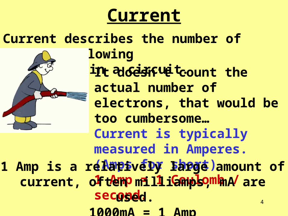
CurrentCurrent describes the number of electrons flowing in a circuit.
It doesn’t count the actual number of electrons, that would be too cumbersome…Current is typically measured in Amperes. (Amps for short)1 Amp = 1 Coulomb / second.
1 Amp is a relatively large amount of current, often milliamps, mA are used.
1000mA = 1 Amp

5
Voltage Sources
No current will flow unless there is a voltage source. This is also known as a potential
difference.
Sometimes, this potential difference is supplied by batteries!
6
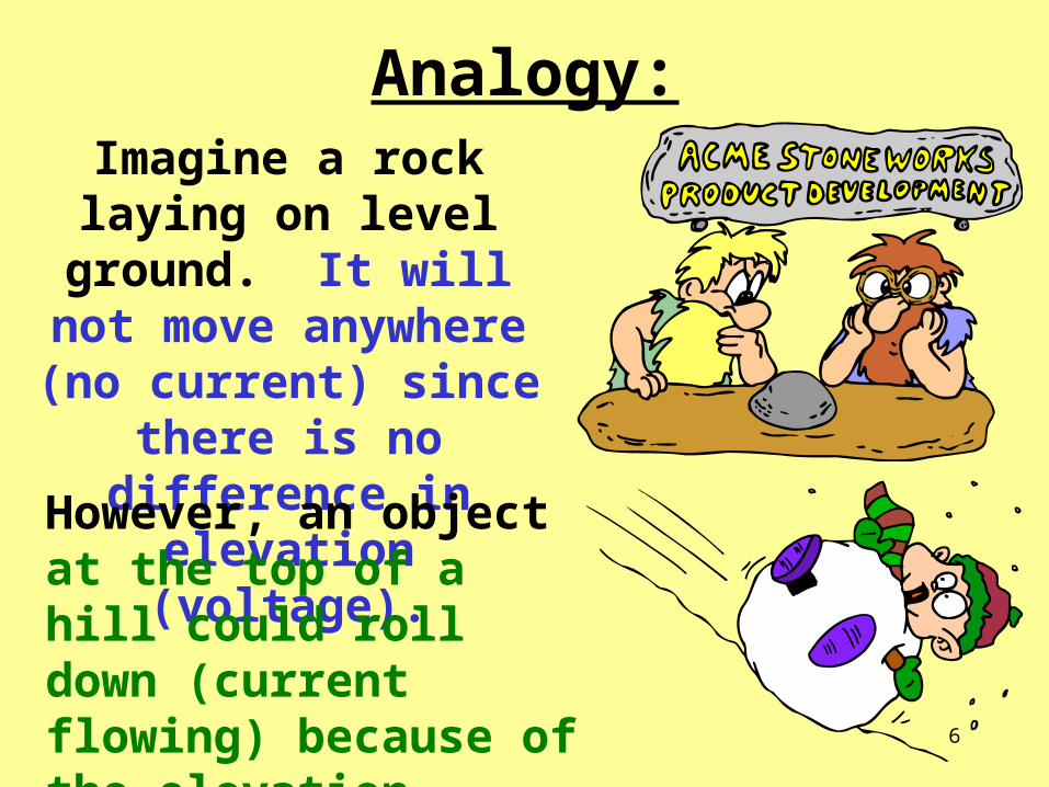
Analogy:Imagine a rock laying on level ground. It will not
move anywhere (no current) since there is no
difference in elevation (voltage).
However, an object at the top of a hill could roll down (current flowing) because of the elevation difference (voltage).

7
Electrical ResistanceIn almost all circuits, the electrons flow with
some opposition or resistance.
Resistance is measured in units called Ohms.
The symbol is the Greek letter omega: ΩVirtually any item that has electricity flowing
through it has some resistance.
Some items have more resistance than others

8
Resistors:Often, the flow of electricity needs to be reduced or controlled. Devices called resistors are used.
The resistance of a wire can depend on several things including:
thickness (area) of wire
temperature of wire
length of wire
9
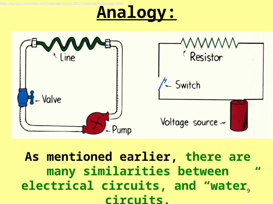
Analogy:
As mentioned earlier, there are many similarities between electrical circuits, and
“water” circuits.
http://faraday.physics.utoronto.ca/IYearLab/Intros/DCI/Flash/WaterAnalogy.html

10
Ohm’s LawMr. Ohm discovered an
extremely useful relationship:
V= I R
Voltage = Current x Resistance
Of course, this formula can be rearranged to solve for whatever is needed...

11
Example:
A light bulb operates on a 110 volt circuit. The bulb draws a current of .91 amps. What is the
resistance of the light bulb?
V=IRR=V/IR=110V/.91A120.8 Ohms, Ω

12
Quick Review:
Electric potential has units of:
Volts, V
Resistance has units of:
Ohms, Ω
Current has units of:
Amperes, A, Amps

13
Shocking?To receive a shock, there must be a voltage
difference applied to you.
( electrons must “roll” downhill)
This is often referred to as a
potential difference.

14
A bird could sit on a high voltage wire and receive no shock at all. Its entire body is at the
same high voltage. No voltage difference.
However, if it touches the ground or tower, then there would be a large voltage difference,
and the current would flow!!!

15
To prevent electric shock, most cords have a third prong that is used to ground the cord.
If there are any extra electrons, they are immediately sent to the ground, not you.

16
Two Types of Current:DC, Direct Current: the
charge flows in one direction only.
Examples: batteries
AC, Alternating Current: electrons in the circuit move in one direction, then switch and
then flow in the opposite direction.
Examples: wall outlets

17
AC Frequency:Since AC current changes direction, or
oscillates, you can describe how often it changes direction.
Almost all US outlets use a frequency of 60 Hz.
18
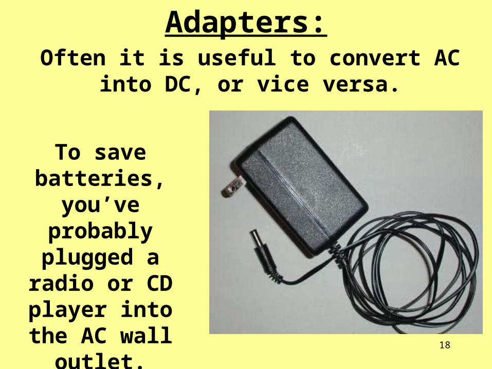
Adapters:Often it is useful to convert AC into DC, or vice
versa.
To save batteries, you’ve probably
plugged a radio or CD player into the
AC wall outlet.

19Notice the input/output voltages, and frequency.
Diodes allow electrons to flow in one direction only. They help change AC into DC.

20
Speedy Electrons?When you complete electric circuits, the information or impulses travel at nearly the speed of light!
However, the electrons themselves don’t travel nearly that fast. It’s actually the electric field that travels that quickly.
The electrons continuously bump into atoms in the conducting metal. These collisions are what cause a
wire to get hot when a lot of current is flowing.

21
Electric Power:Just like mechanical power, electrical power
describes work done per unit of time:
1 Watt = 1 Joule / 1 second
1000 Watts = 1 kilowatt
In terms of electrical quantities, power can be calculated by multiplying current x voltage.
P = I V
22
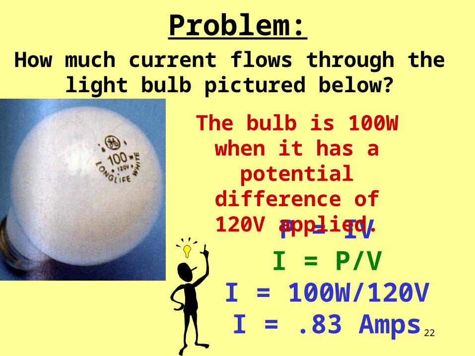
Problem:How much current flows through the light bulb
pictured below?
P = IVI = P/V
I = 100W/120VI = .83 Amps
The bulb is 100W when it has a potential
difference of 120V applied.
23
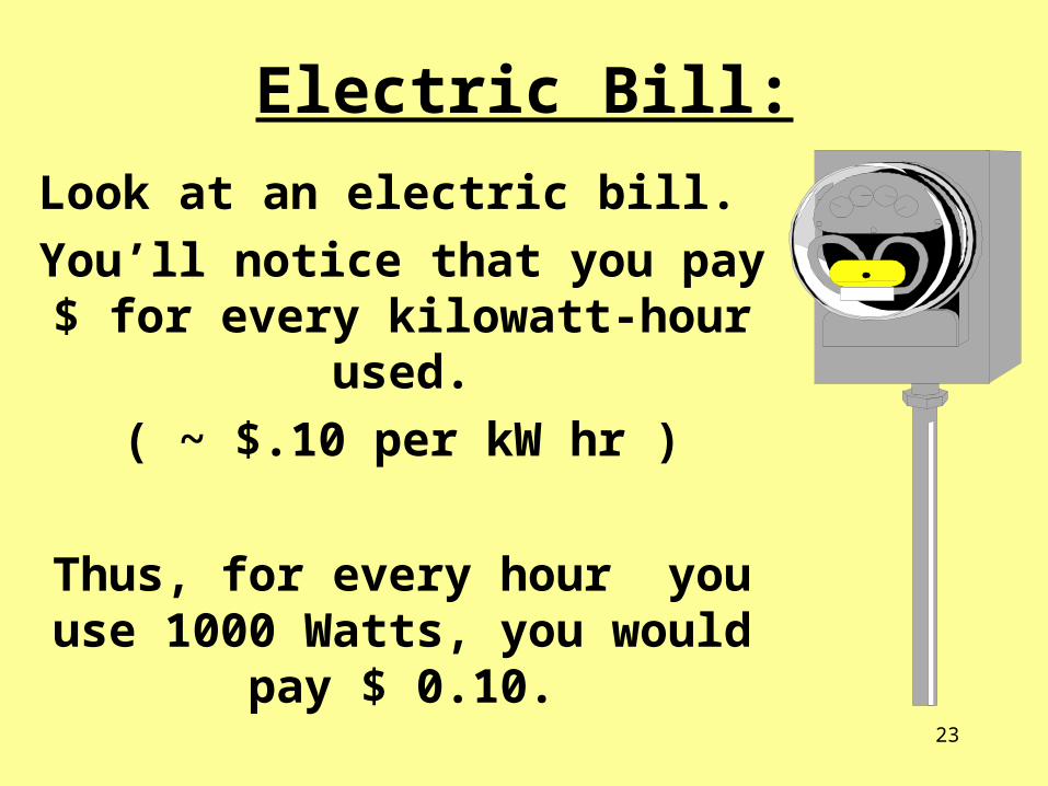
Electric Bill:
Look at an electric bill.
You’ll notice that you pay $ for every kilowatt-hour used.
( ~ $.10 per kW hr )
Thus, for every hour you use 1000 Watts, you would pay $ 0.10.
A kilowatt hr is a unit of energy.

24
Problem:Maybe your parents are always telling you to turn off the lights and save electricity/money? Look at the light bulb below, how much would it cost to run it for 4 hours? ($0.10 per kW hr)
100W = .1 kW
.1 kW x 4 hrs = .4 kW hrs
.4kW hrs x $.10 = $.04!

25
Series and Parallel Circuits:

26
Series Circuits:One simple way to arrange components in an
electrical circuit is to create one large continuous loop with the components:
2 batteries
switch
Light bulb
resistorConventionalCurrent

27
Series Circuits:One simple way to arrange components in an
electrical circuit is to create one large continuous loop with the components:
28
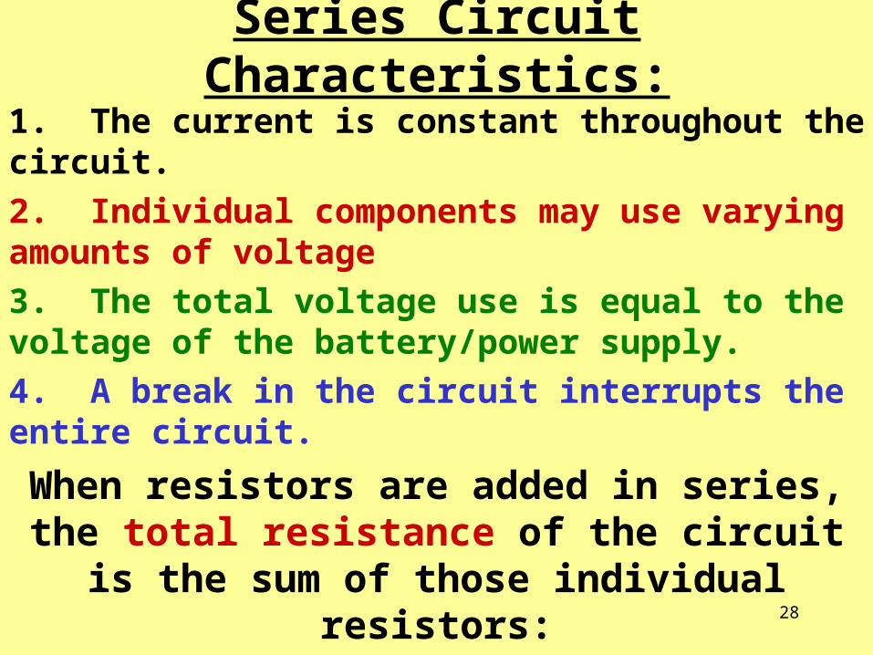
Series Circuit Characteristics:
1. The current is constant throughout the circuit.
2. Individual components may use varying amounts of voltage
3. The total voltage use is equal to the voltage of the battery/power supply.
4. A break in the circuit interrupts the entire circuit.
When resistors are added in series, the total resistance of the circuit is the sum of those
individual resistors:
RT = R1 + R2 + R3...

29
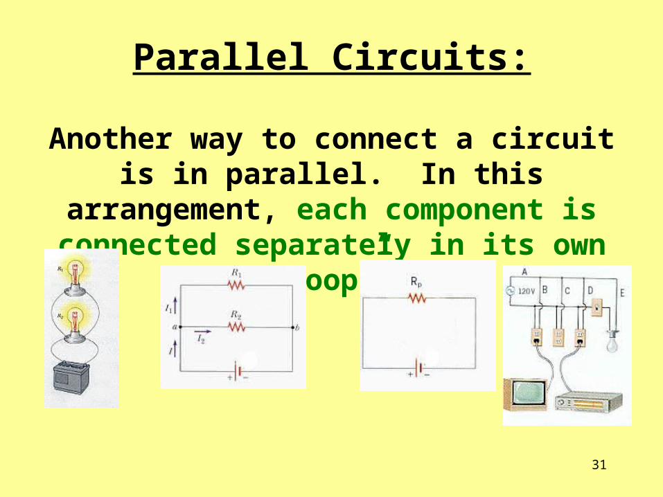
Parallel Circuits:
Another way to connect a circuit is in parallel. In this arrangement, each component is connected separately in its own “loop”.
2 batteries
3 resistors in parallel

30
Parallel Circuits:
Another way to connect a circuit is in parallel. In this arrangement, each component is connected separately in its own “loop”.
31
Parallel Circuits:
Another way to connect a circuit is in parallel. In this arrangement, each component is connected separately in its own “loop”.

32
Parallel Circuit Characteristics:1. The current in the different branches can vary.
2. The total current of the circuit is the sum of the individual branches.
3. All branches of the circuit receive the same voltage of the battery/power supply.
4. A break in one loop doesn’t affect the others.
To find the equivalent resistance of resistors added in parallel:
1/RT = 1/R1 + 1/R2 + 1/R3 +…

33
Too Many Resistors?:Adding more and more devices in parallel decreases the total or overall resistance. This allows too much current to flow! Obviously this can be dangerous!
Fuses and Circuit Breakers:To prevent too much current from causing a fire, fuses are designed to melt and break the circuit before that happens.
Today, most homes have circuit breakers. These
don’t melt, but are switched off to interrupt
the circuit.

34
Meters:Meters:
A A multimetermultimeter can measure voltage, current can measure voltage, current and resistance. resistance.
Meters can provide either Meters can provide either digitaldigital or or analoganalog readouts.readouts.
Digital Analog

35
Measuring Current:
Current can be measured using an ammeter or a multimeter.
A meter that only measures current iscalled an ammeter.
36
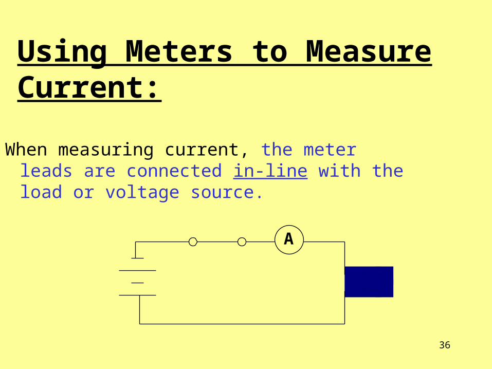
Using Meters to Measure Current:
When measuring current, the meter leads are connected in-line with the load or voltage source.
A
37
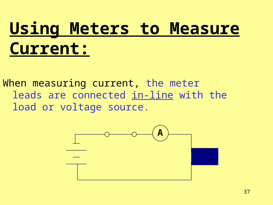
Using Meters to Measure Current:
When measuring current, the meter leads are connected in-line with the load or voltage source.
A

38
Connecting a Meter to Measure Current:
Notice that the meterNotice that the meter
leads or probes areleads or probes are
placed placed in-line with the with the
load. This is called a load. This is called a
series connection. connection.

39
Using Meters to Measure Voltage:
When measuring voltage, the meter leads (probes) are placed across the load or voltage source.
V

40
Connecting a Meter to Measure Voltage:
Notice that the meter
leads or probes are
placed across the
load. This is called a
parallel connection.

41
Meter Settings:
Both the function (DCV, DCA, etc.) switch and the range (0-2V, 0-20V, etc.) switch must be checked and set every time you use a meter - do this before you turn the meter on!
Remember: Remember: Connecting Connecting meters up incorrectly can meters up incorrectly can damage the meter, the damage the meter, the load or device being load or device being measured and expose you measured and expose you to electrical shock!to electrical shock!

42
Series Circuits:One simple way to arrange components in an
electrical circuit is to create one large continuous loop with the components:
2 batteries
switch
Light bulb
resistorConventionalCurrent

43