1 ECE 683 Computer Network Design & Analysis Note 2: Applications and Layered Architectures.
58
1 ECE 683 Computer Network Design & Analysis Note 2: Applications and Layered Architectures
-
Upload
scarlett-dawson -
Category
Documents
-
view
219 -
download
0
Transcript of 1 ECE 683 Computer Network Design & Analysis Note 2: Applications and Layered Architectures.

1
ECE 683Computer Network Design & Analysis
Note 2: Applications and Layered Architectures

2
Outline
• Protocols, Services & Layering• OSI Reference Model• TCP/IP Model• How the Layers Work Together• Application Layer Protocols & Utilities• Sockets

3
Layers, Services & Protocols• The overall communication process between
two or more machines connected across one or more networks is very complex
• Layering partitions related communication functions into groups that are manageable
• Each layer provides a service to the layer above
• Each layer operates according to a protocol• A protocol is a set of rules that govern how two
or more communicating parties are to interact
4
Why Layering?• Layering simplifies design, implementation, and testing
by partitioning overall communication process into parts• Protocols in each layer can be designed separately from
those in other layers and make “calls” for services from layer below
• Layering provides flexibility for modifying and evolving protocols and services without having to change layers below and above
• Monolithic non-layered architectures are costly, inflexible, and soon obsolete

5
Web Browsing Application• World Wide Web allows users to access resources (i.e.
documents) located in computers connected to the Internet
• Documents are prepared using HyperText Markup Language (HTML)
• A browser application program is used to access the web
• The browser displays HTML documents that include links to other documents
• Each link references a Uniform Resource Locator (URL) that gives the name of the machine and the location of the given document
• Let’s see what happens when a user clicks on a link

6
• User clicks on http://www.nytimes.com/• URL contains Internet name of machine (
www.nytimes.com), but not Internet address• Internet needs Internet address to send information to a
machine• Browser software uses Domain Name System (DNS)
protocol to send query for Internet address• DNS system responds with Internet address
Q. www.nytimes.com?
A. 64.15.247.2001. DNS

7
• Browser software uses HyperText Transfer Protocol (HTTP) to send request for document
• HTTP server waits for requests by listening to a well-known port number (80 for HTTP)
• HTTP client sends request messages through an “ephemeral port number,” e.g. 1127
• HTTP needs a Transmission Control Protocol (TCP) connection between the HTTP client and the HTTP server to transfer messages reliably
TCP Connection RequestFrom: 128.100.11.13 Port 1127To: 64.15.247.200 Port 80
2. TCPACK, TCP Connection RequestFrom: 64.15.247.200 Port 80 To:128.100.11.13 Port 1127
ACK
8
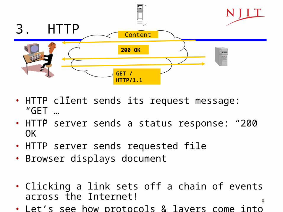
• HTTP client sends its request message: “GET …”• HTTP server sends a status response: “200 OK”• HTTP server sends requested file• Browser displays document
• Clicking a link sets off a chain of events across the Internet!
• Let’s see how protocols & layers come into play…
GET / HTTP/1.1
200 OK
3. HTTP Content
9
Example: HTTP
• HTTP is an application layer protocol• Retrieves documents on behalf of a browser
application program• HTTP specifies fields in request messages and
response messages– Request types; Response codes– Content type, options, cookies, …
• HTTP specifies actions to be taken upon receipt of certain messages
10
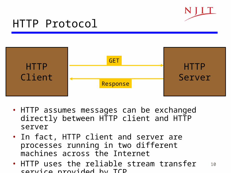
HTTPClient
HTTP Protocol
GET
Response
HTTPServer
• HTTP assumes messages can be exchanged directly between HTTP client and HTTP server
• In fact, HTTP client and server are processes running in two different machines across the Internet
• HTTP uses the reliable stream transfer service provided by TCP
11
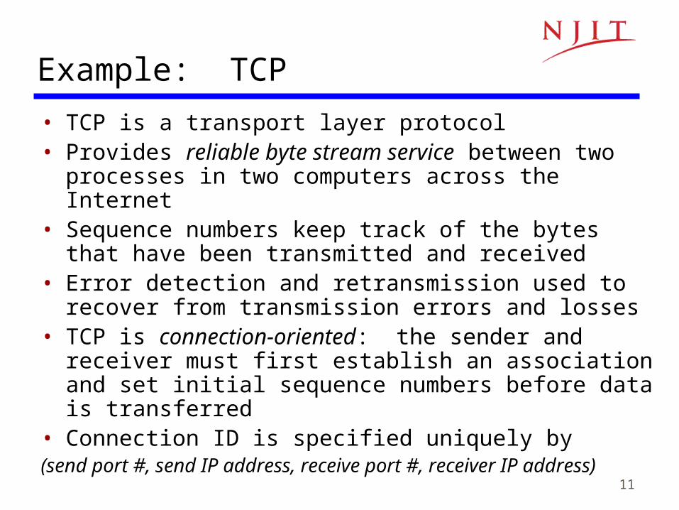
Example: TCP
• TCP is a transport layer protocol• Provides reliable byte stream service between two
processes in two computers across the Internet• Sequence numbers keep track of the bytes that have been
transmitted and received• Error detection and retransmission used to recover from
transmission errors and losses• TCP is connection-oriented: the sender and receiver must
first establish an association and set initial sequence numbers before data is transferred
• Connection ID is specified uniquely by (send port #, send IP address, receive port #, receiver IP address)

12
HTTPserver
HTTPclient
TCP
Port 80Port 1127
HTTP uses service of TCP
TCP
ResponseGET
TCP80, 1127 GET 1127, 80 bytesResponseGETResponse
13
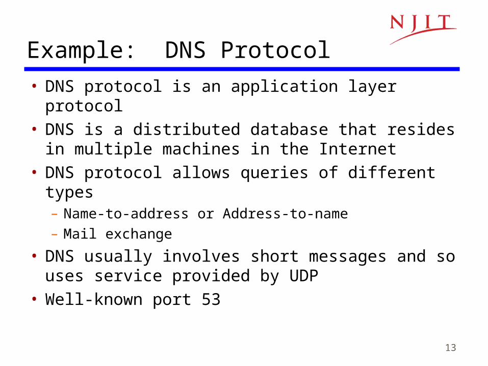
Example: DNS Protocol
• DNS protocol is an application layer protocol• DNS is a distributed database that resides in
multiple machines in the Internet• DNS protocol allows queries of different types
– Name-to-address or Address-to-name– Mail exchange
• DNS usually involves short messages and so uses service provided by UDP
• Well-known port 53
14
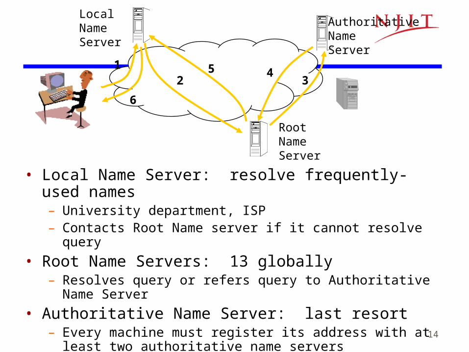
• Local Name Server: resolve frequently-used names– University department, ISP– Contacts Root Name server if it cannot resolve query
• Root Name Servers: 13 globally– Resolves query or refers query to Authoritative Name Server
• Authoritative Name Server: last resort– Every machine must register its address with at least two
authoritative name servers
12 3
45
6
LocalNameServer
RootNameServer
AuthoritativeNameServer

15
Example: UDP• UDP is a transport layer protocol• Provides best-effort datagram service between
two processes in two computers across the Internet
• Port numbers distinguish various processes in the same machine
• UDP is connectionless• Datagram is sent immediately• Quick, simple, but not reliable

16
Summary• Layers: related communication functions
– Application Layer: HTTP, DNS– Transport Layer: TCP, UDP– Network Layer: IP
• Services: a protocol provides a communication service to the layer above– TCP provides connection-oriented reliable byte transfer
service– UDP provides best-effort datagram service
• Each layer builds on services of lower layers– HTTP builds on top of TCP– DNS builds on top of UDP– TCP and UDP build on top of IP
17
Note 2: Applications and Layered Architectures
OSI Reference Model

18
Open Systems Interconnection• Network architecture:
– Definition of all the layers – Design of protocols for every layer
• By the 1970s every computer vendor had developed its own proprietary layered network architecture
• Problem: computers from different vendors could not be networked together
• Open Systems Interconnection (OSI) was an international effort by the International Organization for Standardization (ISO) to enable multivendor computer interconnection
19
OSI Reference Model• Describes a seven-layer abstract reference model for a
network architecture• Purpose of the reference model was to provide a
framework for the development of protocols• OSI also provided a unified view of layers, protocols,
and services which is still in use in the development of new protocols
• Detailed standards were developed for each layer, but most of these are not in use
• TCP/IP protocols preempted deployment of OSI protocols

20
7-Layer OSI Reference Model
ApplicationLayer
PresentationLayer
SessionLayer
TransportLayer
NetworkLayer
Data LinkLayer
PhysicalLayer
ApplicationLayer
PresentationLayer
SessionLayer
TransportLayer
NetworkLayer
Data LinkLayer
PhysicalLayer
NetworkLayer
Application Application
Data LinkLayer
PhysicalLayer
NetworkLayer
Data LinkLayer
PhysicalLayer
Communicating End SystemsOne or More Network Nodes
End-to-End Protocols
21
Physical Layer
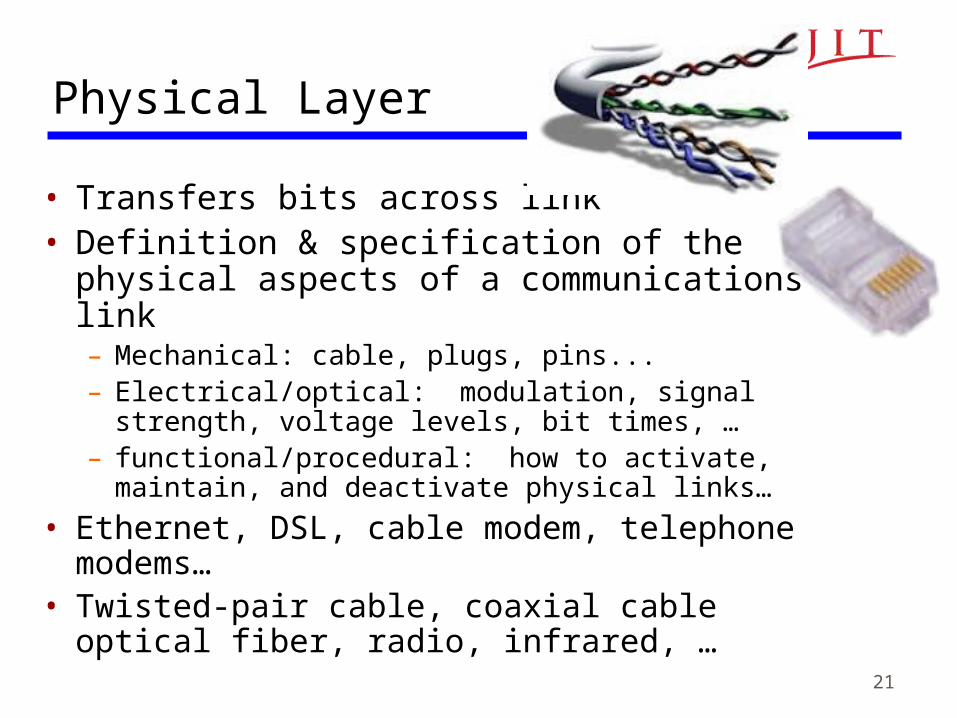
• Transfers bits across link• Definition & specification of the physical
aspects of a communications link– Mechanical: cable, plugs, pins...– Electrical/optical: modulation, signal strength, voltage
levels, bit times, …– functional/procedural: how to activate, maintain, and
deactivate physical links…
• Ethernet, DSL, cable modem, telephone modems…
• Twisted-pair cable, coaxial cable optical fiber, radio, infrared, …
22
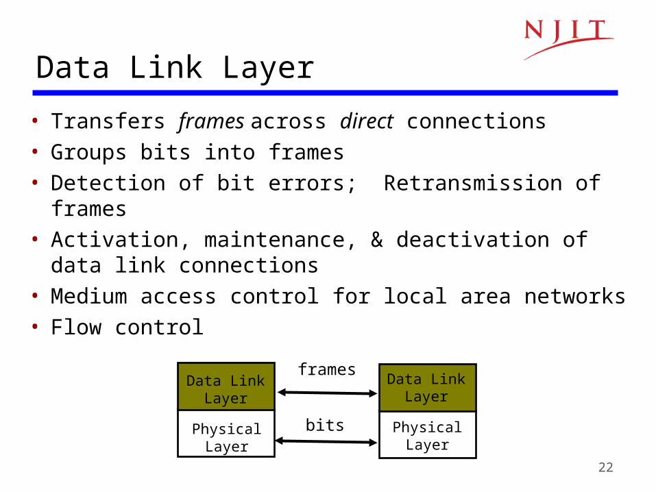
Data Link Layer
• Transfers frames across direct connections
• Groups bits into frames
• Detection of bit errors; Retransmission of frames
• Activation, maintenance, & deactivation of data link connections
• Medium access control for local area networks
• Flow control
Data LinkLayer
PhysicalLayer
Data LinkLayer
PhysicalLayer
frames
bits

23
Network Layer
• Transfers packets across multiple links and/or multiple networks
• Addressing must scale to large networks• Nodes jointly execute routing algorithm to
determine paths across the network• Congestion control to deal with traffic surges• Connection setup, maintenance, and teardown
when connection-based

24
Internetworking• Internetworking is part of network layer and provides transfer
of packets across multiple possibly dissimilar networks• Gateways (routers) direct packets across networks
G = gateway H = host
Net 1
Net 5
Net 3
Net 2
HNet 3
G
H
H
H
GG
GG
G
Net 1
Net 2 Net 4
Net 5
Ethernet LAN
ATMSwitch
ATMSwitch
ATMSwitch
ATMSwitch
ATMNetwork
25
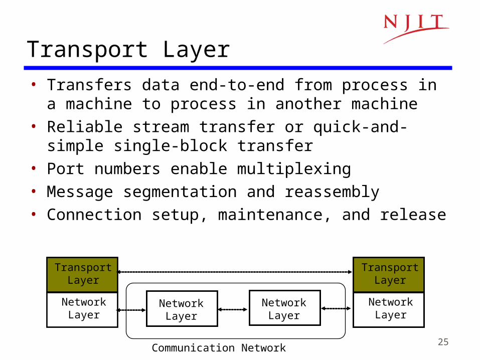
Transport Layer• Transfers data end-to-end from process in a machine to
process in another machine• Reliable stream transfer or quick-and-simple single-
block transfer• Port numbers enable multiplexing• Message segmentation and reassembly• Connection setup, maintenance, and release
TransportLayer
NetworkLayer
TransportLayer
NetworkLayer
NetworkLayer
NetworkLayer
Communication Network

26
Application & Upper Layers• Application Layer: Provides
services that are frequently required by applications: DNS, web access, file transfer, email…
• Presentation Layer: machine-independent representation of data…
• Session Layer: dialog management, recovery from errors, …
ApplicationLayer
PresentationLayer
SessionLayer
TransportLayer
Application
ApplicationLayer
TransportLayer
Application
Incorporated into Application Layer

27
Headers & Trailers• Each protocol uses a header that carries addresses,
sequence numbers, flag bits, length indicators, etc…• CRC check bits may be appended for error detection
ApplicationLayer
TransportLayer
NetworkLayer
Data LinkLayer
PhysicalLayer
ApplicationLayer
TransportLayer
NetworkLayer
Data LinkLayer
PhysicalLayer
Application ApplicationAPP DATA
AH APP DATA
TH AH APP DATA
NH TH AH APP DATA
DH NH TH AH APP DATA CRC
bits
28
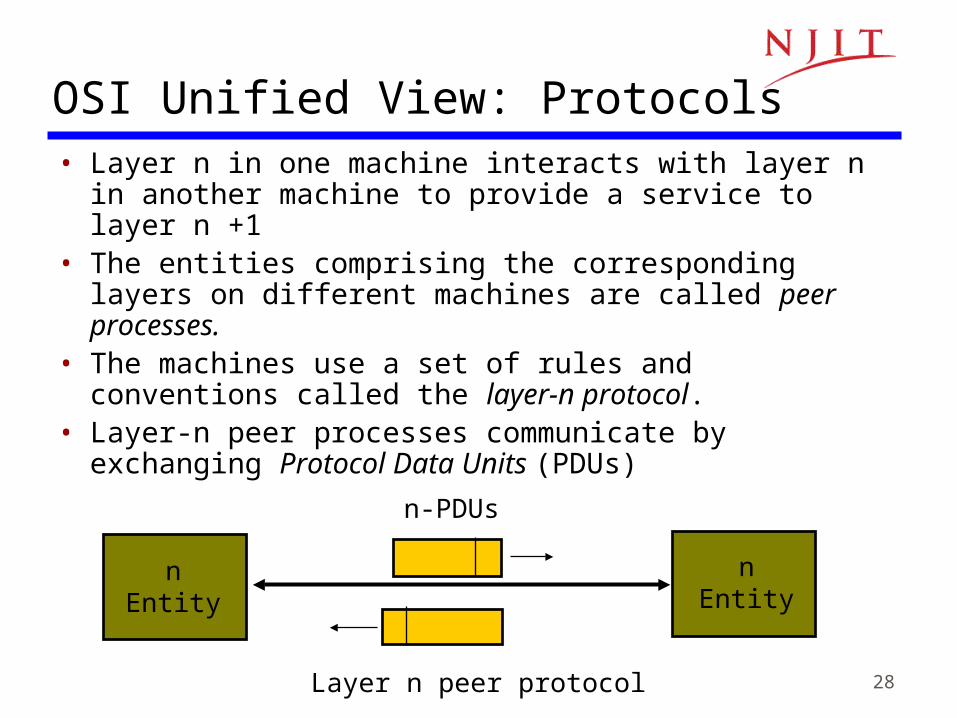
OSI Unified View: Protocols• Layer n in one machine interacts with layer n in another
machine to provide a service to layer n +1• The entities comprising the corresponding layers on
different machines are called peer processes.• The machines use a set of rules and conventions called
the layer-n protocol.• Layer-n peer processes communicate by exchanging
Protocol Data Units (PDUs)
nEntity
nEntity
Layer n peer protocol
n-PDUs

29
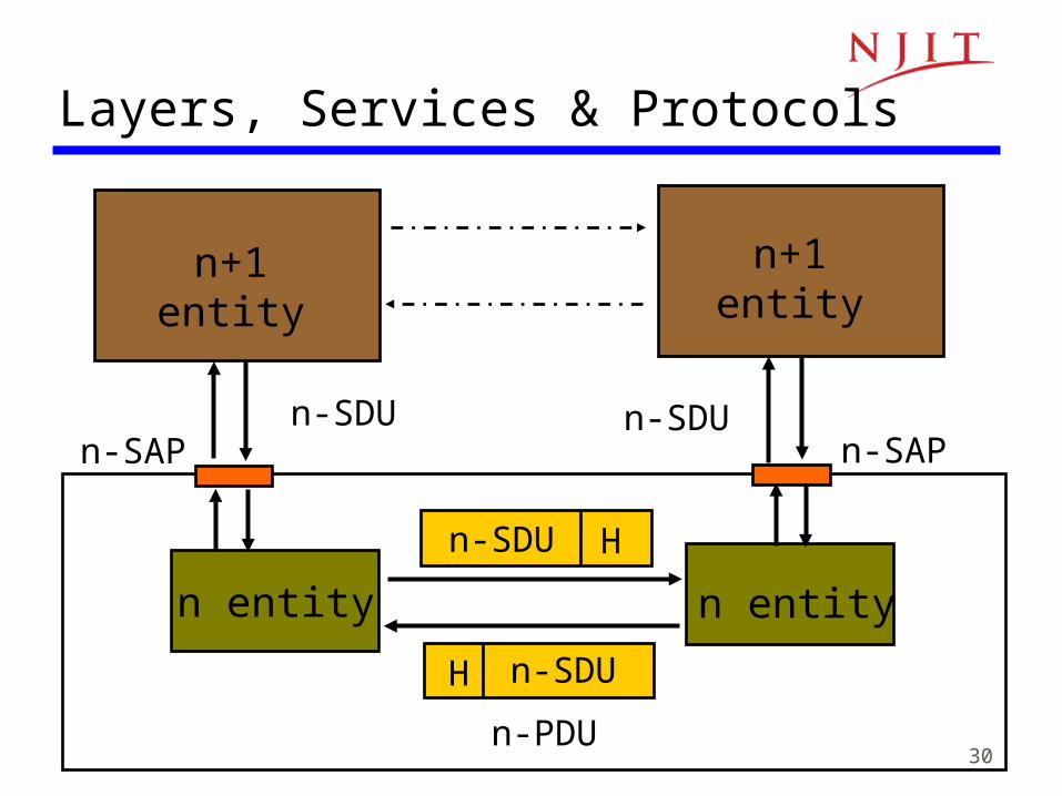
OSI Unified View: Services• Communication between peer processes is virtual
and actually indirect• Layer n+1 transfers information by invoking the
services provided by layer n • Services are available at Service Access Points
(SAP’s)• Each layer passes data & control information to the
layer below it until the physical layer is reached and transfer occurs
• The data passed to the layer below is called a Service Data Unit (SDU)
• SDU’s are encapsulated in PDU’s
30
n+1entity
n-SAP
n+1entity
n-SAP
n entity n entity
n-SDU
n-SDU
n-SDU
H
H n-SDU
n-PDU
Layers, Services & Protocols
31
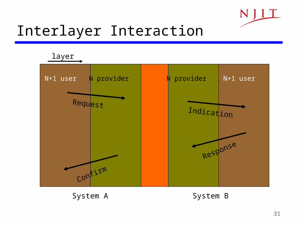
Interlayer Interaction
layer
N+1 user N provider
System A System B
N provider N+1 user
RequestIndication
Response
Confirm

32
Connectionless & Connection-Oriented Services
• Connection-Oriented– Three-phases:
1. Connection setup between two SAPs to initialize state information
2. SDU transfer
3. Connection release
– E.g. TCP, ATM
• Connectionless– Immediate SDU transfer
– No connection setup
– E.g. UDP, IP
• Layered services need not be of same type– TCP operates over IP
– IP operates over ATM

33
Confirmed vs Unconfirmed Service
• Confirmed service– The sender must eventually be informed of the
outcome– E.g., connection setup is usually a confirmed service
• Unconfirmed service– The sender need not be informed of the outcome– A connectionless service can be confirmed or
unconfirmed

34
n-PDU
Segmentation & Reassembly• A layer may impose a limit on
the size of a data block that it can transfer for implementation or other reasons
• Thus a layer-n SDU may be too large to be handled as a single unit by layer-(n-1)
• Sender side: SDU is segmented into multiple PDUs
• Receiver side: SDU is reassembled from sequence of PDUs
n-SDU
n-PDU n-PDU n-PDU
Segmentation(a)
n-SDU
n-PDU n-PDU
Reassembly(b)
35
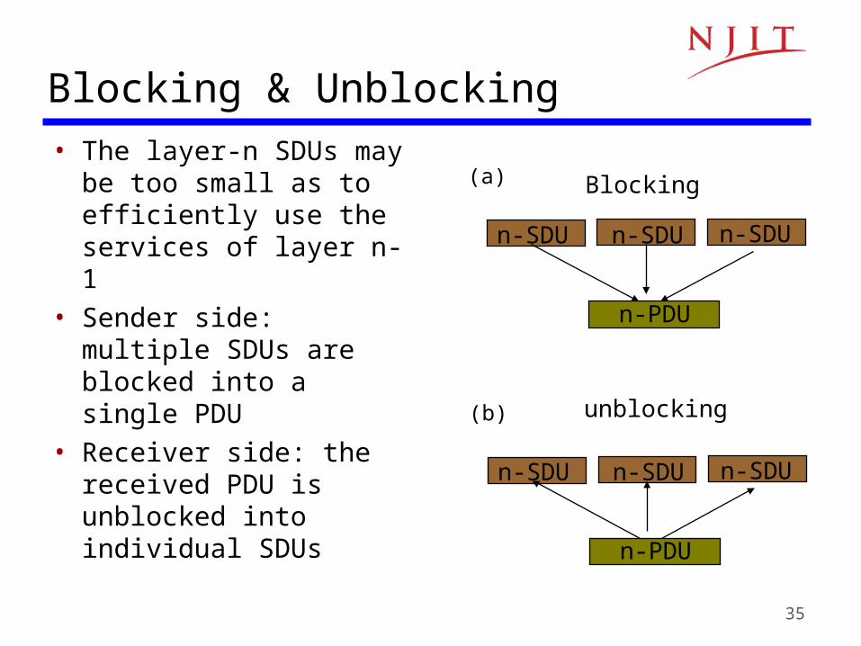
Blocking & Unblocking• The layer-n SDUs may
be too small as to efficiently use the services of layer n-1
• Sender side: multiple SDUs are blocked into a single PDU
• Receiver side: the received PDU is unblocked into individual SDUs
n-SDU n-SDU n-SDU
Blocking(a)
unblocking(b)
n-PDU
n-SDU n-SDU n-SDU
n-PDU

36
n+1entity
n+1entity
n+1entity
n+1entity
Multiplexing
• Sharing of layer n service by multiple layer n+1 users• Multiplexing tag or ID required in each PDU to determine
which users an SDU belongs to
n entity n entity
n-SDUn-SDU
n-SDUH
H n-SDU
n-PDU

37
Splitting
• Splitting involves the use of several layer-n services to support a single layer-(n+1) user
• Recombining is done at the destination to group multiple n-PDUs into a single n-SDU
• Splitting can improve the transmission reliability when the underlying transmission mechanism is prone to errors
• Splitting is also useful when the transfer rate required by a user exceeds the transfer rate available from individual services

38
Note 2: Applications and Layered Architectures
TCP/IP ArchitectureHow the Layers Work Together
39
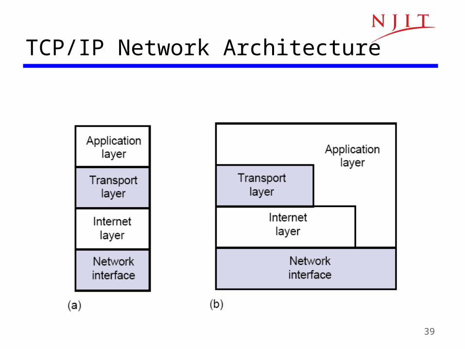
TCP/IP Network Architecture

40
Internet & Network Interface Layers
41
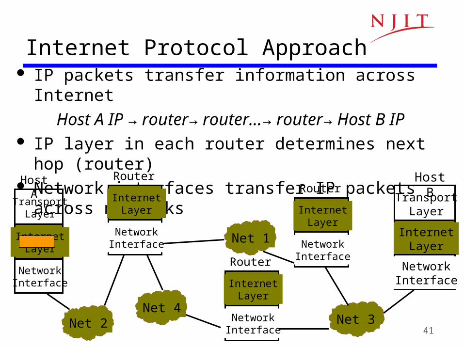
Internet Protocol Approach IP packets transfer information across Internet
Host A IP → router→ router…→ router→ Host B IP IP layer in each router determines next hop (router) Network interfaces transfer IP packets across networks
Router
InternetLayer
NetworkInterface
TransportLayer
InternetLayer
NetworkInterface
TransportLayer
InternetLayer
NetworkInterface
Host A Host B
Net 5Net 1
Net 5Net 2 Net 5Net 3
Router
InternetLayer
NetworkInterface
Router
InternetLayer
NetworkInterface
Net 5Net 4
42
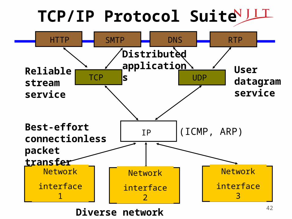
TCP/IP Protocol Suite
(ICMP, ARP)
Diverse network technologies
Reliable stream service
Userdatagram service
Distributed applications
HTTP SMTP RTP
TCP UDP
IP
Network
interface 1
Network
interface 3
Network
interface 2
DNS
Best-effort connectionless packet transfer

43
Comparison of OSI and TCP/IP
OSI v TCP/IPOSI v TCP/IP

44
Internet Names & AddressesInternet Names• Each host has a unique name
– Independent of physical location
– Facilitate memorization by humans
– Domain Name– Organization under single
administrative unit• Host Name
– Name given to host computer• User Name
– Name assigned to user
Internet Addresses• Each host has globally unique logical
32 bit IP address• Separate address for each physical
connection to a network • Routing decision is done based on
destination IP address • IP address has two parts:
– netid and hostid– netid unique – netid facilitates routing
• Dotted Decimal Notation:int1.int2.int3.int4(intj = jth octet)128.100.10.13
DNS resolves IP name to IP address

45
Physical Addresses• LANs (and other networks) assign physical addresses to
the physical attachment to the network • The network uses its own address to transfer frames to
the appropriate destination• IP address needs to be resolved to physical address at
each IP network interface• Example: Ethernet uses 48-bit addresses
– Each Ethernet network interface card (NIC) has globally unique Medium Access Control (MAC) or physical address
– First 24 bits identify NIC manufacturer; second 24 bits are serial number
– 00:90:27:96:68:07 12 hex numbers
Intel
46
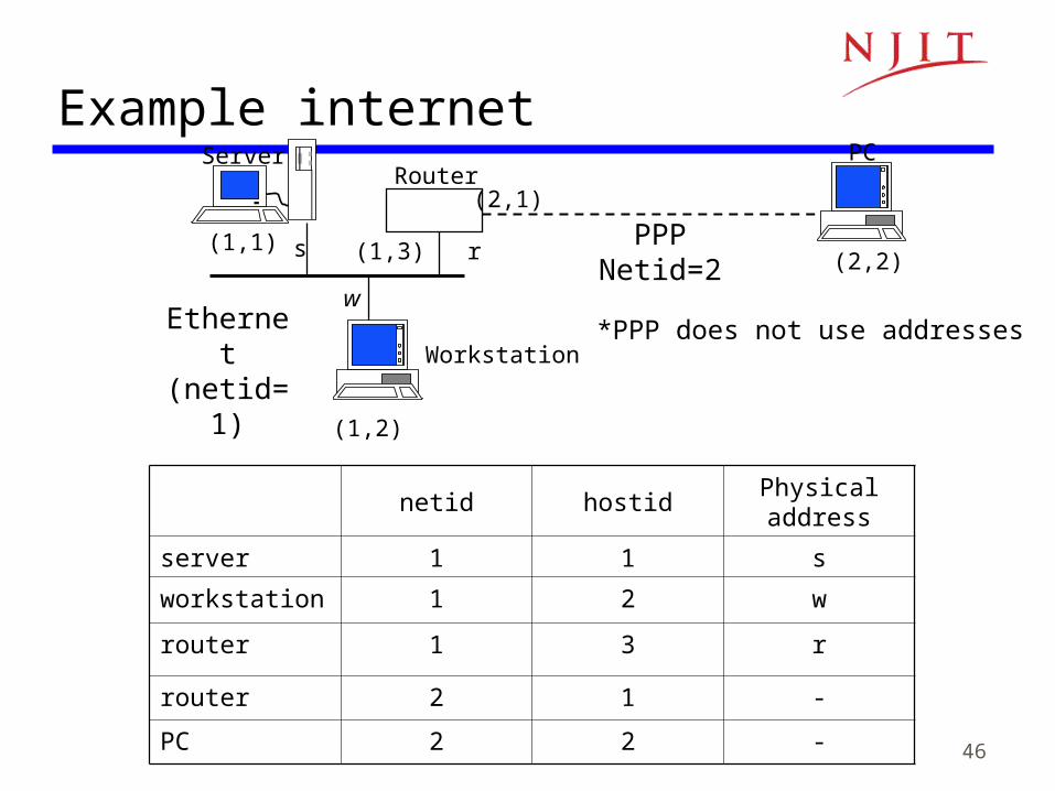
Example internet
(1,1) s
(1,2)
w
(2,1)
(1,3) r (2,2)PPP
Netid=2
Ethernet(netid=1)
PCServerRouter
Workstation
netid hostidPhysical address
server 1 1 s
workstation 1 2 w
router 1 3 r
router 2 1 -
PC 2 2 -
*PPP does not use addresses
47
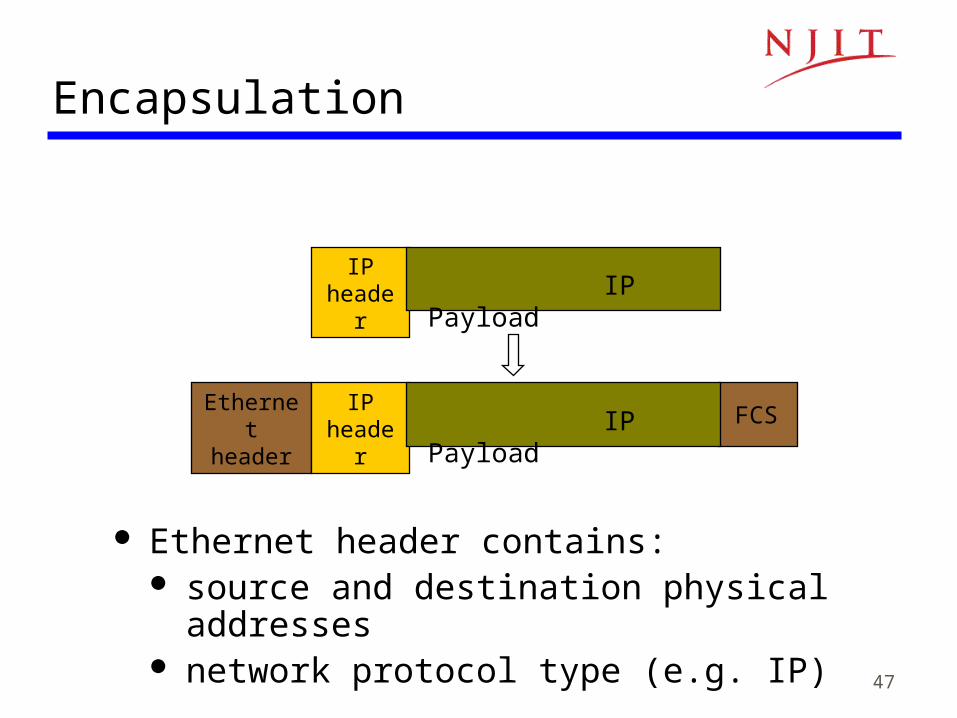
Encapsulation
Ethernet header contains: source and destination physical addresses network protocol type (e.g. IP)
IP header IP Payload
Ethernet header
FCSIP
header IP Payload
48
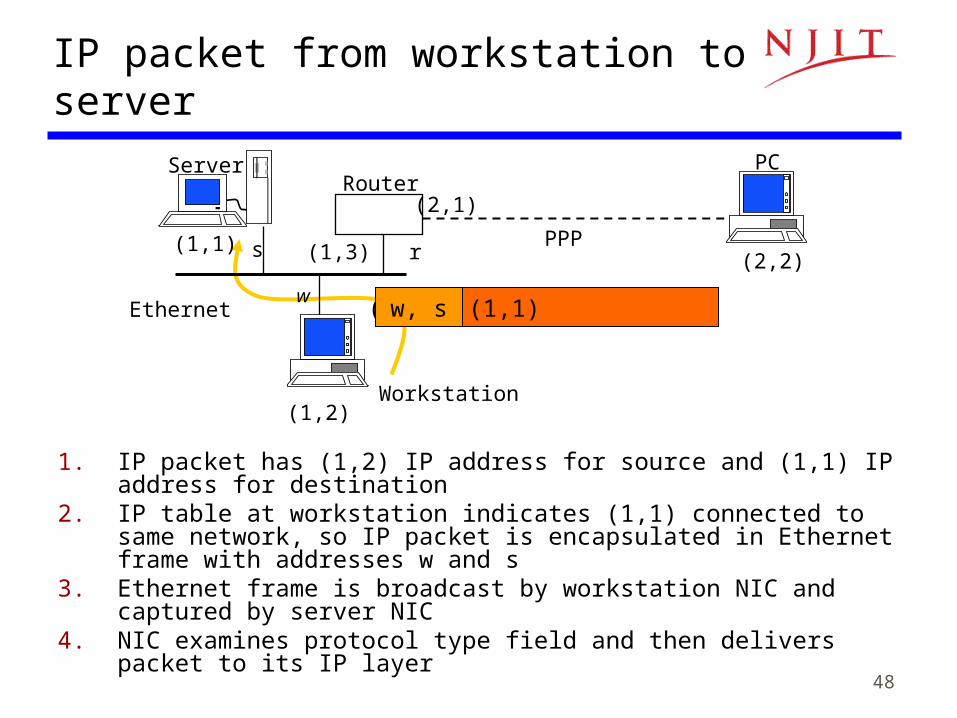
IP packet from workstation to server
1. IP packet has (1,2) IP address for source and (1,1) IP address for destination
2. IP table at workstation indicates (1,1) connected to same network, so IP packet is encapsulated in Ethernet frame with addresses w and s
3. Ethernet frame is broadcast by workstation NIC and captured by server NIC
4. NIC examines protocol type field and then delivers packet to its IP layer
(1,1) s
(1,2)
w
(2,1)
(1,3) r (2,2)PPP
Ethernet
PCServerRouter
Workstation
(1,2), (1,1) w, s

49
IP packet from server to PC
(1,1) s
(1,2)
w
(2,1)
(1,3) r (2,2)
PCServerRouter
Workstation
1. IP packet has (1,1) and (2,2) as IP source and destination addresses 2. IP table at server indicates packet should be sent to router, so IP packet is
encapsulated in Ethernet frame with addresses s and r3. Ethernet frame is broadcast by server NIC and captured by router NIC4. NIC examines protocol type field and then delivers packet to its IP layer5. IP layer examines IP packet destination address and determines IP packet
should be routed to (2,2)6. Router’s table indicates (2,2) is directly connected via PPP link7. IP packet is encapsulated in PPP frame and delivered to PC8. PPP at PC examines protocol type field and delivers packet to PC IP layer
(1,1), (2,2) s, r
(1,1), (2,2)
50
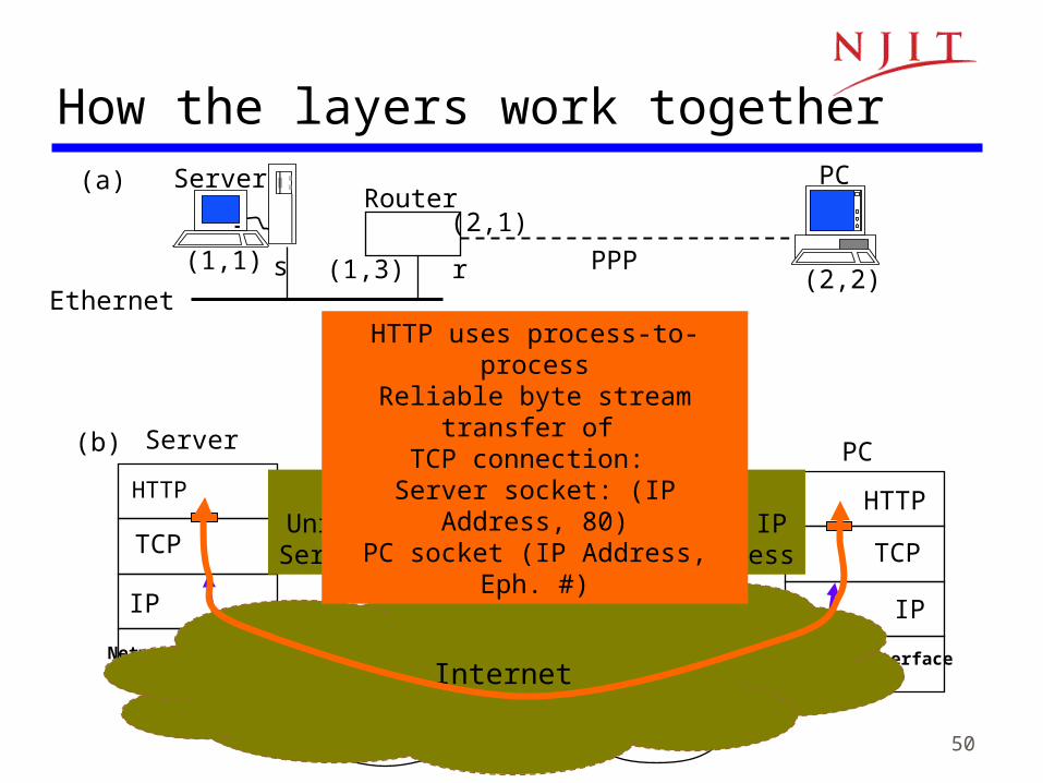
How the layers work together
Network interface
IP
TCP
HTTP
Network interface
IP
Network interface
IP
TCP
HTTP
Ethernet PPPRouter
(1,1) s
(2,1)
(1,3) r (2,2)PPP
Ethernet
(a)
(b) Server PC
PCServerRouter
TCP uses node-to-node Unreliable packet transfer of IP
Server IP address & PC IP address
Internet
HTTP uses process-to-processReliable byte stream transfer of
TCP connection: Server socket: (IP Address, 80)PC socket (IP Address, Eph. #)
51
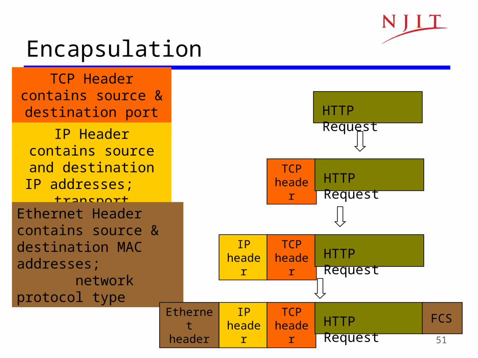
Encapsulation
TCP Header contains source & destination
port numbers
IP Header contains source and destination
IP addresses; transport protocol type
Ethernet Header contains source & destination MAC addresses; network protocol type
HTTP Request
TCP header HTTP Request
IP header
TCP header HTTP Request
Ethernet header
IP header
TCP header HTTP Request FCS

52
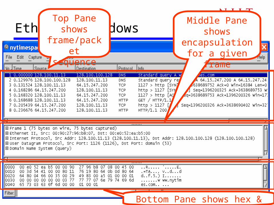
• User clicks on http://www.nytimes.com/• Ethereal network analyzer captures all frames observed
by its Ethernet NIC• Sequence of frames and contents of frame can be
examined in detail down to individual bytes
How the layers work together: Network Analyzer Example
Internet
53
Ethereal windowsTop Pane
shows frame/packet
sequence
Middle Pane shows
encapsulation for a given frame
Bottom Pane shows hex & text

54
Top pane: frame sequenceDNS
Query
TCP Connection
SetupHTTP
Request & Response

55
Middle pane: Encapsulation
Ethernet Frame
Ethernet Destination and
Source Addresses
Protocol Type

56
Middle pane: Encapsulation
IP Packet
IP Source and Destination Addresses
Protocol Type
And a lot of other stuff!

57
Middle pane: Encapsulation
TCP Segment
Source and Destination Port
Numbers
HTTP Request
GET

58
Summary
• Encapsulation is key to layering• IP provides for transfer of packets across
diverse networks• TCP and UDP provide universal
communications services across the Internet• Distributed applications that use TCP and UDP
can operate over the entire Internet• Internet names, IP addresses, port numbers,
sockets, connections, physical addresses