1 Dr. rer. nat. Lars Grunske, Boeing Postdoctoral Research Fellow, School of ITEE, ARC Centre for...
23
Dr. rer. nat. Lars Grunske, Boeing Postdoctoral Research Fellow, School of ITEE, ARC Centre for Complex Systems 1 An Automated Failure Mode and Effect Analysis based on High-Level Design Specification with Behavior Trees Lars Grunske, Peter Lindsay, Nisansala Yatapanage, Kirsten Winter ARC Centre for Complex Systems School of Information Technology and Electrical Engineering, University of Queensland, Brisbane, QLD 4072, [email protected]
-
Upload
arnold-sharp -
Category
Documents
-
view
215 -
download
0
Transcript of 1 Dr. rer. nat. Lars Grunske, Boeing Postdoctoral Research Fellow, School of ITEE, ARC Centre for...

Dr. rer. nat. Lars Grunske, Boeing Postdoctoral Research Fellow, School of
ITEE, ARC Centre for Complex Systems 1
An Automated Failure Mode and Effect Analysis based on High-Level Design Specification with Behavior Trees
Lars Grunske, Peter Lindsay, Nisansala Yatapanage, Kirsten Winter
ARC Centre for Complex Systems
School of Information Technology and Electrical Engineering,
University of Queensland, Brisbane, QLD 4072,

Dr. rer. nat. Lars Grunske, Boeing Postdoctoral Research Fellow, School of
ITEE, ARC Centre for Complex Systems 2
Agenda
Problem description/context Preliminaries
Behavior Trees
Automated Hazard Analysis Procedure Overview Generation of Design Behavior Trees Generation of Fault View BTs Identification and Specification of Hazard Conditions Model Checking (SAL Toolkit) Generation of FMEA-tables
Case-Study Industrial Metal Press
Conclusion

Dr. rer. nat. Lars Grunske, Boeing Postdoctoral Research Fellow, School of
ITEE, ARC Centre for Complex Systems 3
Motivation
Problem Context Safety-critical software-intensive systems Automotive electronics, aviation, industrial process control and
medical applications
Problem Increasing complexity
Goal Model and analyze safety-critical behaviors early in the
development lifecycle Systematic and integrated approach for safety analysis Automate Failure Modes and Effects Analysis (FMEA) Tool support that automates the tedious and error-prone aspects of
FMEA

Dr. rer. nat. Lars Grunske, Boeing Postdoctoral Research Fellow, School of
ITEE, ARC Centre for Complex Systems 4
Preliminaries

Dr. rer. nat. Lars Grunske, Boeing Postdoctoral Research Fellow, School of
ITEE, ARC Centre for Complex Systems 5
Behavior Trees
Behavior Tree Graphical notation to capture the functional
requirements Textual requirements are translated into
individual requirements trees These individual requirement trees are merged
into one integrated requirements tree Stepwise, structured approach, Semi automatic Early error detection
Literature: Dromey, R.G.: From requirements to design:
Formalizing the key steps. In: Int. Conference on Software Engineering and Formal Methods (SEFM 2003), IEEE Computer Society (2003) 2-13
GSE: Genetic Software Engineering: http://www.sqi.gu.edu.au/gse

Dr. rer. nat. Lars Grunske, Boeing Postdoctoral Research Fellow, School of
ITEE, ARC Centre for Complex Systems 6
Behavior Tree Syntax (1)
Basic Syntax Elements
Reversion, Synchronisation
^ =

Dr. rer. nat. Lars Grunske, Boeing Postdoctoral Research Fellow, School of
ITEE, ARC Centre for Complex Systems 7
Behavior Tree Syntax (2)
Control flow in Behavior Trees

Dr. rer. nat. Lars Grunske, Boeing Postdoctoral Research Fellow, School of
ITEE, ARC Centre for Complex Systems 8
Generation of Design Behavior Trees
Goal Decomposition of the integrated requirements BT into component
BTs. Interactions are modeled by message passing (BT events)
Process (semi-automatic) Identify controller, sensor, and actuator components and the
environment (Following the usual architecture of reactive systems) Each component forms a thread in the overall system Parallel composition of the components and environment
Literature Wen, L., Dromey, R.G.: From requirements change to design change:
A formal path. In: Int. Conference on Software Engineering and Formal Methods (SEFM 2004), IEEE Computer Society (2004) 104-113

Dr. rer. nat. Lars Grunske, Boeing Postdoctoral Research Fellow, School of
ITEE, ARC Centre for Complex Systems 9
Automated Hazard Analysis
An Automated Failure Mode and Effect Analysis based on High-Level Design
Specification with Behavior Trees

Dr. rer. nat. Lars Grunske, Boeing Postdoctoral Research Fellow, School of
ITEE, ARC Centre for Complex Systems 10
Procedure Overview
Precondition Design BT Description of
the hazard conditions
Component fault specification
Procedure Inject faults into the design BT fault view BT Translate the fault view BT to SAL code Identify LTL-formulas for the hazard conditions Model-check the system

Dr. rer. nat. Lars Grunske, Boeing Postdoctoral Research Fellow, School of
ITEE, ARC Centre for Complex Systems 11
Generation of Fault View BTs
A Fault View BT describes the behavior of the system when it is affected by one or more component faults. Fault injection Prune the design BT (Omission Failure) Add failure behavior (Commission Failure)
Example Failure: component C is unable to reach state c: Tree is pruned at C ??c?? branch
A[ a ]
B?? b ??
C?? c ??
D[ d ]
E[ e ]
A[ a ]
B?? b ??
D[ d ]
Fault View BTOriginal BT
Dr. rer. nat. Lars Grunske, Boeing Postdoctoral Research Fellow, School of
ITEE, ARC Centre for Complex Systems 12
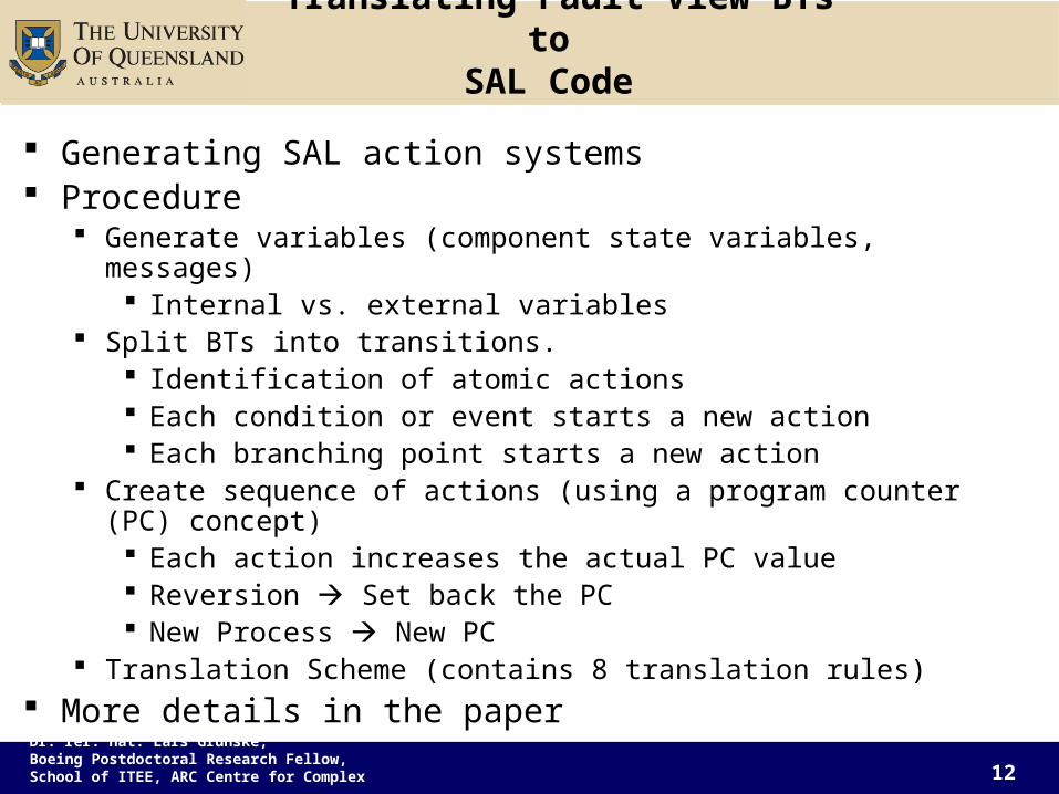
Translating Fault View BTs to SAL Code
Generating SAL action systems Procedure
Generate variables (component state variables, messages) Internal vs. external variables
Split BTs into transitions. Identification of atomic actions Each condition or event starts a new action Each branching point starts a new action
Create sequence of actions (using a program counter (PC) concept) Each action increases the actual PC value Reversion Set back the PC New Process New PC
Translation Scheme (contains 8 translation rules) More details in the paper

Dr. rer. nat. Lars Grunske, Boeing Postdoctoral Research Fellow, School of
ITEE, ARC Centre for Complex Systems 13
Identification and Specification of Hazard Conditions
Hazard identification Not the scope of this project Bidirectional search cause-consequence relationships Traditional techniques can be used
Hazard Specification LTL formula Safety Patterns (Natural Language Templates for Specifying LTL/CTL)
Bitsch, F.: Safety patterns - the key to formal specification of safety requirements. In: Int. Conference on Computer Safety, Reliability and Security (SAFECOMP2001). Volume 2187 of LNCS., Springer-Verlag (2001) 176-189
M. B. Dwyer, G. S. Avrunin, and J. C. Corbett. Patterns in Property Specifications for Finite-State Verification. In 21st International Conference on Software Engineering, Los Angeles, May 1999.

Dr. rer. nat. Lars Grunske, Boeing Postdoctoral Research Fellow, School of
ITEE, ARC Centre for Complex Systems 14
Model Checking& Generation of FMEA-tables
LTL model checker of the SAL Toolkit (http://sal.csl.sri.com/)
We check, if the model of the fault view BT is able to reach a state in which the hazard conditions (LTL formula) is true. If yes, we receive a counter example
Trace: initial state hazardous state Fault propagation Hint for design changes
If no, the injected fault(s) does not produce a hazard Generation of FMEA table
Based on the model checking results Including the counter examples (illustrated)
Dr. rer. nat. Lars Grunske, Boeing Postdoctoral Research Fellow, School of
ITEE, ARC Centre for Complex Systems 15
Case Study
Industrial Metal Press

Dr. rer. nat. Lars Grunske, Boeing Postdoctoral Research Fellow, School of
ITEE, ARC Centre for Complex Systems 16
Industrial Metal Press
Source: McDermid, J., Kelly, T.: Industrial press: Safety case. Technical report, High Integrity Systems Engineering Group, University of York (1996)
Top sensor
PoNR sensor
Bottom sensor
PLC
Button
Plunger
Drive chain
Motor
Clutches
Guard

Dr. rer. nat. Lars Grunske, Boeing Postdoctoral Research Fellow, School of
ITEE, ARC Centre for Complex Systems 17
Top sensor
PoNR sensor
Bottom sensor
PLC
Button
Plunger
Drive chain
Motor
Clutches
Guard
Industrial Metal PressBehaviour Description
Press main functions: Raise plunger to top (open the press) Release plunger (close the press) Abort operation (stop closing &
reopen the press) System-level
requirements/operational concept: Upon start-up, press will open fully If button is pushed while press is fully
open, press will start to close
Upon closing, press will automatically reopen
If safe to do so, closing can be aborted by releasing the button Safe = above Point of No Return
(PoNR)

Dr. rer. nat. Lars Grunske, Boeing Postdoctoral Research Fellow, School of
ITEE, ARC Centre for Complex Systems 18
Design Behavior Tree Industrial Metal Press (complete and small )

Dr. rer. nat. Lars Grunske, Boeing Postdoctoral Research Fellow, School of
ITEE, ARC Centre for Complex Systems 19
Safety Requirements (Negated Hazard Conditions)
HC1. If the plunger is at the top and the operator is not pushing the button, the motor should remain on.
G ((plunger = attop operator = releasebutton) (motor = on))
HC2. If the plunger is falling below the PONR, known as falling fast, the motor should remain off.
G ((plunger = fallingfast) (motor = off ))
HC3. If the plunger is falling above the PONR, known as falling slow, and the operator releases the button, the motor should eventually turn on, before the plunger changes state.
G ((plunger = fallingslow operator = releasebutton)
(plunger = fallingslow U motor = on))
HC4. The motor should never turn off while the plunger is rising.
G ( (plunger = risingbelowPONR plunger = risingabovePONR) (motor = off )))

Dr. rer. nat. Lars Grunske, Boeing Postdoctoral Research Fellow, School of
ITEE, ARC Centre for Complex Systems 20
Component Failure HC1 HC2 HC3 HC4 No failures Top stuck Low Top stuck High X Bottom stuck Low Bottom stuck High X PONR stuck Low X PONR stuck High X Button stuck released Button stuck pushed X X Motor stuck on Motor stuck off
Key: = hazard condition does not arise; X = hazard condition can occur.
Results
HC1. If the plunger is at the top and the operator is not pushing the button, the motor should remain on.HC2. If the plunger is falling below the PONR, known as falling fast, the motor should remain off.HC3. If the plunger is falling above the PONR, known as falling slow, and the operator releases the button, the motor should eventually turn on, before the plunger changes state.HC4. The motor should never turn off while the plunger is rising.

Dr. rer. nat. Lars Grunske, Boeing Postdoctoral Research Fellow, School of
ITEE, ARC Centre for Complex Systems 21
Tool Support BTE & BTFail
http://www.sqi.gu.edu.au/gse/tools/
Dr. rer. nat. Lars Grunske, Boeing Postdoctoral Research Fellow, School of
ITEE, ARC Centre for Complex Systems 22
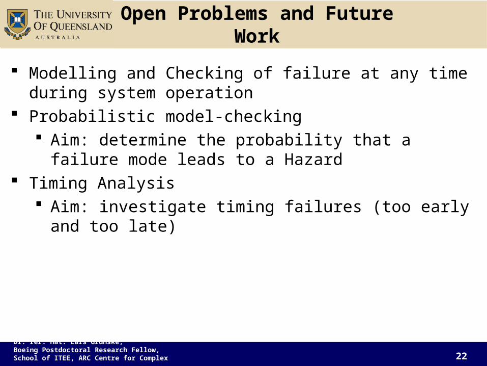
Open Problems and Future Work
Modelling and Checking of failure at any time during system operation
Probabilistic model-checking Aim: determine the probability that a failure mode leads to
a Hazard Timing Analysis
Aim: investigate timing failures (too early and too late)

Dr. rer. nat. Lars Grunske, Boeing Postdoctoral Research Fellow, School of
ITEE, ARC Centre for Complex Systems 23
Conclusion
Contribution: Automation of FMEA Automatic Fault Injection + Model Checking
Benefits: Tool support that automates the tedious and error-prone aspects of FMEA Systematic and integrated approach for safety analysis
Thanks!
Questions?