1 Design Group 2 Kat Donovan - Team Leader Andrew DeBerry Mike Kinder John Mack Jeff Newcamp Andrew...
18
1 Design Group 2 Kat Donovan - Team Leader Andrew DeBerry Mike Kinder John Mack Jeff Newcamp Andrew Prisbell Nick Schumacher Conceptual Design for AME 441 Spring 2004
-
date post
19-Dec-2015 -
Category
Documents
-
view
215 -
download
0
Transcript of 1 Design Group 2 Kat Donovan - Team Leader Andrew DeBerry Mike Kinder John Mack Jeff Newcamp Andrew...

1
Design Group 2
Kat Donovan - Team LeaderAndrew DeBerry
Mike KinderJohn Mack
Jeff NewcampAndrew Prisbell
Nick Schumacher
Conceptual Designfor AME 441Spring 2004

2
Group 2 – Ducted Design

3
Overview
Aircraft Configuration & Design DriversComparison AircraftCAD ModelsSpreadsheet Decisions
♣ Airfoil Choice♣ Engine Selection♣ Weight & Drag Estimates♣ Static Stability
Conclusions & Lessons LearnedDesign & Build Schedule

4
Aircraft Configuration (Requirements)Powered by electric motorCarry specified payloadTake-off in < 300 feet on grassPlanform area between 400 in2 & 800 in2
Radio control system with up to 7 channels
Design DriversMaximize the climb rate
Maximize the level flight speed

5
Comparison Aircraft
* Information from http://www.aerospaceweb.org/aircraft/bomber/yb49/† Information from http://www.aerospaceweb.org/aircraft/bomber/b2/‡ Information from Design and Construction of a Remote Piloted Flying Wing, May 2, 1994

6
CAD Models
Electronics Box Battery Pack (x2) Circuit Card
Servo GPS Receiver Modem
7
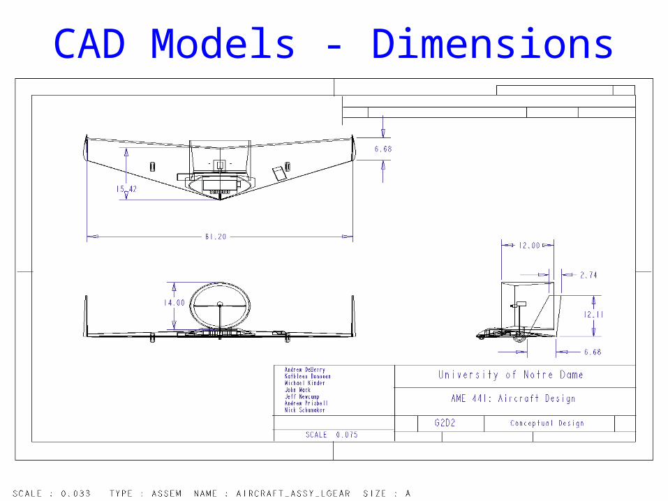
CAD Models - Dimensions

8
NACA 6412♣ Low Reynolds
Number airfoil♣ t/c ratio large
enough to house internal electronics
Airfoil Choice
9
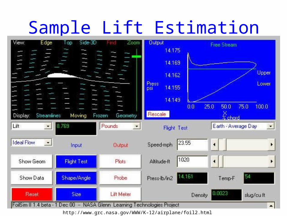
Sample Lift Estimation
http://www.grc.nasa.gov/WWW/K-12/airplane/foil2.html

10
Engine Selection: Astro Cobalt 15Model No. p/n 615G
Name 05 Geared
Gear Ratio 2.38 to 1
Armature Winding 7 turns
Armature Resistance 0.069 ohms
Magnet Type Sm Cobalt
Bearings Ball Bearings
Motor Speed 1488 rpm/volt
Geared Motor Speed 652 rpm/volt
Motor Torque/amp 0.91 in-oz /amp
Geared Torque 2.17 in-oz /amp
Voltage Range 8 to 12 volts
No Load Currrent 2 amps
Maximum Continuous Current 25 amps
Maximum Continuous Power 400 watts
Gear Motor Length 3.3 inches
Motor Diameter 1.3 inches
Motor Shaft Diameter 5/32 inch
Prop Shaft Diameter 1/4 inch
Gear Motor Weight 9 oz
Data from www.astroflight.com
Electric, brushless motorRuns off 16-cell
rechargeable battery pack

11
Power EstimateVelocity vs. Power
0
50
100
150
200
250
0 50 100 150 200
Velocity (ft/s)
Po
wer
(h
p)
Full Throttle
90% Throttle
80% Throttle
70% Throttle
Power Required

12
Thrust Estimates
Climb Rate vs. Thrust to Weight Ratio
0.3
0.4
0.5
0.6
0.7
250 300 350 400 450 500
Rate of Climb (ft/min)
Thru
st to
Wei
ght R
atio

13
Thrust, Drag, Estimates
14
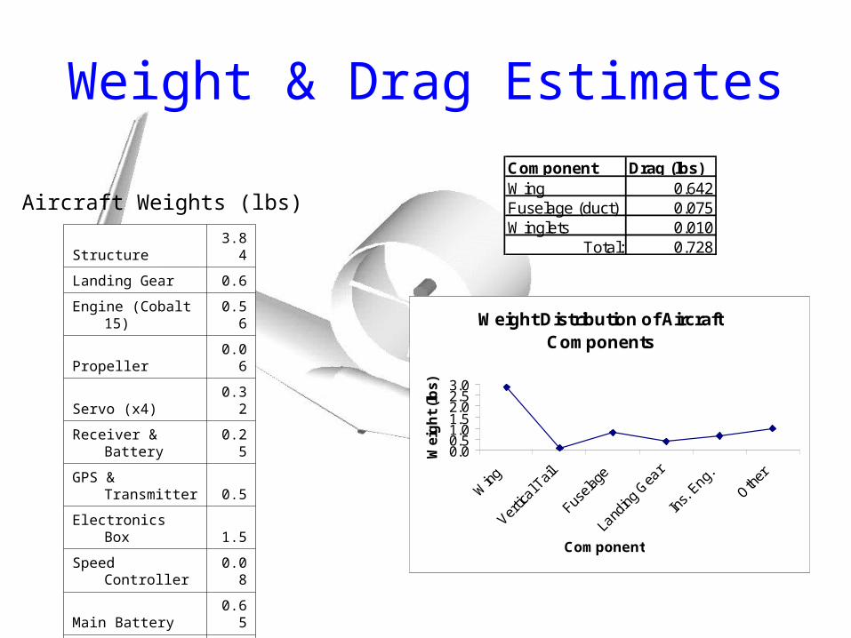
Weight & Drag Estimates
Weight Distribution of Aircraft Components
0.00.51.01.52.02.53.0
Wing
Vertic
al Tail
Fusela
ge
Land
ing G
ear
Ins.
Eng.
Other
Component
Wei
gh
t (l
bs)
Structure 3.84
Landing Gear 0.6
Engine (Cobalt 15) 0.56
Propeller 0.06
Servo (x4) 0.32
Receiver & Battery 0.25
GPS & Transmitter 0.5
Electronics Box 1.5
Speed Controller 0.08
Main Battery 0.65
Total: 8.36
Aircraft Weights (lbs)
Component Drag (lbs)Wing 0.642Fuselage (duct) 0.075Winglets 0.010
Total: 0.728

15
Static Stability
Load Summary (fuselage)Load Type Magnitude x/L_start x/L_end resultant M @C_lift dw
(lbs) x/L f-lb (+ cw)Fuel 0.00 0.00 0.00 0 0.0000000 0.00Payload 2.65 0.00 0.50 0.25 -0.5605769 0.24Fus.Struct. 0.77 0.30 0.95 0.625 0.1255045 0.05Engine(s) 0.62 0.60 0.78 0.69 0.1422173 0.14Wing Struct. 2.84 0.00 1.00 0.5 0.1092308 0.14Horiz. Tail 0.00 0.00 1.00 0.5 0.0000000 0.00Vert. Tail 0.10 0.66 1.00 0.83 0.0368462 0.01Other 0.98 0.00 0.50 0.25 -0.2077747 0.09
S L 7.96 S M -0.3545528
Static Margin 0.045891 stableC_M_a -0.824338 stableC_n_b 0.01287 stableC_L_b -0.01287 stable
Fuselage Length
L (f) 2
Wing Center of Lift
L_ctr (x/L) 0.461538 8.307692
m.a.c. (ft) 0.97 2.910884

16
Conclusions & Lessons Learned
Flying wing to maximize rate of climb and level cruise speed
Ducted fan to increase propeller efficiencyWinglets to reduce dragTricycle landing wheels to prevent damage
during landingAt least 24” separation of modem and GPS
to limit interference

17
Design & Build Schedule
26 February: Present Detailed Design
4 March: Complete Parts List
16 March: Fabrication
6-9 April: Ground Tests
13-22 April: Flight Tests
18
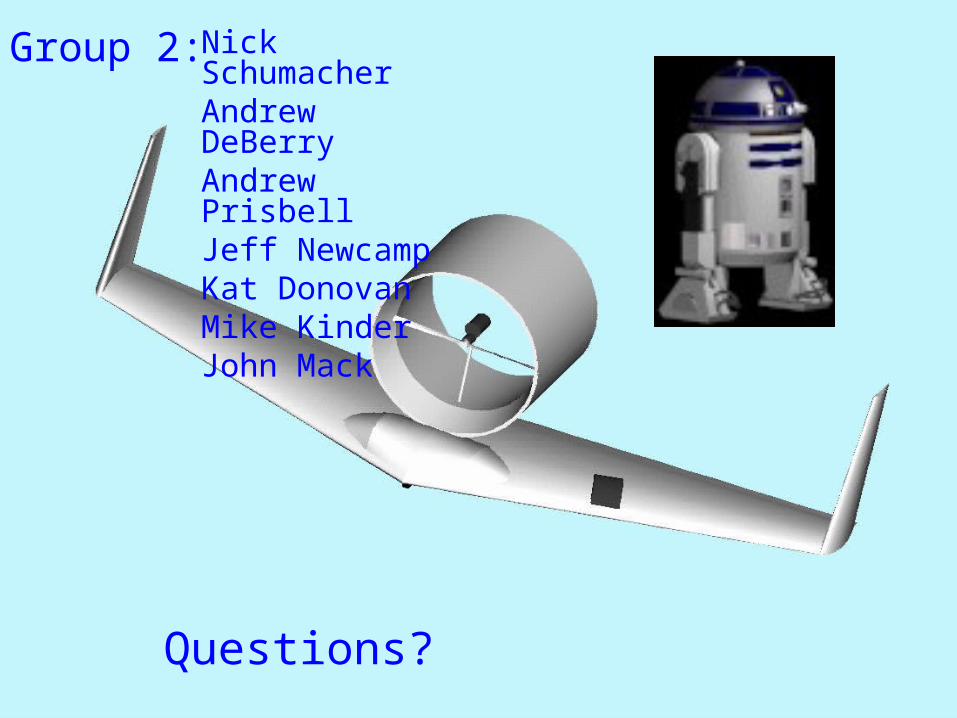
Group 2: Nick SchumacherAndrew DeBerryAndrew PrisbellJeff NewcampKat DonovanMike KinderJohn Mack
Questions?