
1. DESCRIPTION 2. 2.1.3APPLICATION Mode of operation 1.1 ...
20
81 EN 3.701.17/04.21 Hydraulic dampers 1. DESCRIPTION 1.1. FUNCTION The pressure fluctuations occurring in hydraulic systems can be cyclical or one- off problems due to: z Flow rate fluctuations from displacement pumps z Actuation of shut-off and control valves with short opening and closing times z Switching on and off of pumps z Sudden linking of spaces with different pressure levels HYDAC hydraulic dampers are particularly suitable for damping such pressure fluctuations. Selecting the most suitable hydraulic damper for each system ensures that: z Vibrations caused by pipes, valves, couplings etc. are minimised and subsequent pipe and valve damage is prevented z Measuring instruments are protected and their performance is no longer impaired z The noise level in hydraulic systems is reduced z The performance of machine tools is improved z Interconnection of several pumps in one line is possible z A pump rpm and feed pressure increase is possible z The maintenance and servicing costs can be reduced z The service life of the system is increased 2. APPLICATION 2.1. PULSATION DAMPING TYPE SB...P / SBO...P without damper 2.1.1 General The HYDAC pulsation damper z Prevents pipe breaks caused by material fatigue, pipe oscillations and irregular flow rates, z Protects valves, control devices and other instruments, z Improves noise level damping 2.1.2 Applications The pulsation damper is particularly suitable for hydraulic systems, displacement pumps, sensitive measurement and control instruments and manifolds, e.g. in process circuits in the chemical industry. 2.1.3 Mode of operation The pulsation damper generally has two fluid ports and can therefore be fitted directly inline. The flow is diverted in the fluid valve so that it is directed straight at the bladder or diaphragm. This causes direct contact of the flow with the bladder or diaphragm which, in an almost inertia-less operation, balances the flow rate fluctuations via the gas volume. It particularly compensates for higher frequency pressure oscillations. The charge pressure is adjusted to individual operating conditions. 2.1.4 Design HYDAC pulsation dampers consist of: z The welded or forged pressure vessel in carbon steel; available with internal coating or in stainless steel for chemically aggressive fluids z The special fluid valve with inline connection, which guides the flow into the vessel (threaded or flange connection) z The bladder or diaphragm in various elastomers as shown in section 4.1. 2.1.5 Installation As close as possible to the pulsation source. Mounting position preferably vertical (gas valve pointing upwards). Preferred and alternative installation positions are shown in schematic form in section 1.3. Time with accumulator (standard connection bladder accumulator) Pressure Time with accumulator as pulsation damper Pressure Time Pressure
Transcript of 1. DESCRIPTION 2. 2.1.3APPLICATION Mode of operation 1.1 ...

81
EN 3
.701
.17/
04.2
1
Hydraulic dampers
1. DESCRIPTION1.1. FUNCTIONThe pressure fluctuations occurring in hydraulic systems can be cyclical or one-off problems due to:
z Flow rate fluctuations from displacement pumps zActuation of shut-off and control valves with short opening and closing times zSwitching on and off of pumps zSudden linking of spaces with different pressure levels
HYDAC hydraulic dampers are particularly suitable for damping such pressure fluctuations.Selecting the most suitable hydraulic damper for each system ensures that:
zVibrations caused by pipes, valves, couplings etc. are minimised and subsequent pipe and valve damage is prevented zMeasuring instruments are protected and their performance is no longer impaired z The noise level in hydraulic systems is reduced z The performance of machine tools is improved z Interconnection of several pumps in one line is possible zA pump rpm and feed pressure increase is possible z The maintenance and servicing costs can be reduced z The service life of the system is increased
2. APPLICATION2.1. PULSATION DAMPING
TYPE SB...P / SBO...Pwithout damper
2.1.1 GeneralThe HYDAC pulsation damper
zPrevents pipe breaks caused by material fatigue, pipe oscillations and irregular flow rates, zProtects valves, control devices and other instruments, z Improves noise level damping
2.1.2 ApplicationsThe pulsation damper is particularly suitable for hydraulic systems, displacement pumps, sensitive measurement and control instruments and manifolds, e.g. in process circuits in the chemical industry.
2.1.3 Mode of operationThe pulsation damper generally has two fluid ports and can therefore be fitted directly inline.The flow is diverted in the fluid valve so that it is directed straight at the bladder or diaphragm. This causes direct contact of the flow with the bladder or diaphragm which, in an almost inertia-less operation, balances the flow rate fluctuations via the gas volume. It particularly compensates for higher frequency pressure oscillations. The charge pressure is adjusted to individual operating conditions.2.1.4 DesignHYDAC pulsation dampers consist of:
z The welded or forged pressure vessel in carbon steel; available with internal coating or in stainless steel for chemically aggressive fluids z The special fluid valve with inline connection, which guides the flow into the vessel (threaded or flange connection) z The bladder or diaphragm in various elastomers as shown in section 4.1.
2.1.5 InstallationAs close as possible to the pulsation source. Mounting position preferably vertical (gas valve pointing upwards).Preferred and alternative installation positions are shown in schematic form in section 1.3.
Time
with accumulator (standard connection bladder accumulator)
Pres
sure
Time
with accumulator as pulsation damper
Pres
sure
Time
Pres
sure

82
EN 3
.701
.17/
04.2
1
2.2. SUCTION FLOW STABILISATION
2.2.1 GeneralThe HYDAC suction flow stabiliser
z Improves the NPSH value of the system zPrevents cavitation of the pump zPrevents pipe oscillations
2.2.2 ApplicationsMain application areas are piston and diaphragm pumps in public utility plants, reactor construction and the chemical industry.2.2.3 Mode of operationTrouble-free pump operation is only possible if no cavitation occurs in the pump suction and pipe oscillations are prevented.A relatively high fluid volume in the suction flow stabiliser in relation to the displacement volume of the pump reduces the acceleration effects of the fluid column in the suction line. An air separation is also achieved due to the extremely low flow rate in the suction flow stabiliser and the deflection on a baffle. By adjusting the charging pressure of the bladder to the operating conditions, the best possible damping is achieved.2.2.4 DesignThe HYDAC suction flow stabiliser consists of a welded vessel in steel or stainless steel. The inlet and outlet are on opposite sides and are separated by a baffle, other versions on request. The upper part houses the encapsulated bladder. In addition, there is a vent screw in the end cap and a drainage facility on the bottom.2.2.5 InstallationAs close as possible to the suction inlet of the pump. Vertical mounting position (gas valve pointing upwards).
2.3. SHOCK ABSORPTION
2.3.1 GeneralThe HYDAC shock absorber
zReduces pressure shocks zProtects pipelines and valves from being destroyed
2.3.2 ApplicationsThe accumulators are particularly suitable for use in pipelines with quick-acting valves or flaps and whilst pumps are being switched on and off.They are also suitable for energy storage in low pressure applications.2.3.3 Mode of operationSudden changes in pipeline flow, such as those caused by pump failure or the closing or opening of valves, can cause pressures which are many times higher than the normal values.The shock absorber prevents this by converting potential energy into kinetic energy and vice versa. This prevents pressure shocks and protects pipelines, valves, monitoring instruments and other pipe fittings from destruction.2.3.4 DesignThe shock absorption can be provided by using bladder, piston and diaphragm accumulators. Further technical details on the individual accumulator types can be found in the following brochure sections:
zBladder accumulators, low pressure No. 3.202 zBladder accumulators, standard design No. 3.201 zDiaphragm accumulators No. 3.100 zPiston accumulators, standard design No. 3.301
2.3.5 InstallationAs close as possible to the source of the erratic condition. Vertical mounting position (gas valve pointing upwards).
without damper
Pres
sure
Time
Pres
sure
with accumulator (standard bladder accumulator)
Time
with accumulator as suction flow stabiliser
Pres
sure
without damper
Pres
sure
Pres
sure
Time
with shock absorber
Time
Time

83
EN 3
.701
.17/
04.2
1
3 SIZING3.1. PULSATION DAMPER AND SUCTION FLOW STABILISER
pressure side
On the suction side and the pressure side of piston pumps there are almost identical conditions in terms of the irregularity of the flow rate. Therefore, the same formulae for determining the effective gas volume are used to calculate the damper size. The fact that two completely different damper types are ultimately used is due to the different acceleration and pressure ratios on the two sides.When selecting the pulsation damper, it is not only the gas volume V0 which is a decisive factor. The connection size of the pump also has to be taken into account. In order to avoid additional cross-section variations, which represent reflection points for vibrations, and to keep pressure drop to a reasonable level, the fitting cross-section of the damper must be the same as that of the pipeline.The gas volume V0 of the damper is determined with the aid of the formula for adiabatic changes of state.By giving the residual pulsation or the gas volume, the damper size can be dimensioned with the aid of the HYDAC software ASP (Accumulator Simulation Program).
suction side
Designations:∆V = fluctuating fluid volume [l] ∆V = m qq = stroke volume [l]
qd
h�κκ=
π ••
2
4dk = piston diameter [dm]hk = piston stroke [dm]m = amplitude factor
m = ∆Vq
z = no. of compressions/ effective cylinders per revolutionx = residual pulsation [± %]κ = isentropic exponentΦ = pressure ratio of pre-charge pressure to operating pressure [0.6 to 0.9]
Φ =ppm0
∆p = amplitude of pressure fluctuations ∆p = p2 - p1 [bar]
Formulae:
Diagram of mounting options:
VV
x x
0 1 1
1100
1100
=
−−
+
Δ
Φ Φκ κ
ΔV q= m •
[ ]xp p
pm
m± =
−% •1 100
=−p pp
m
m
2 100•
Alternative installation configuration using standard accumulator with a T-piece with reduced damping effect
Preferred installation configuration with maximum damping effect

84
EN 3
.701
.17/
04.2
1
Temperature [°C]
Isen
tropi
c ex
pone
nt κ
Amplitude factor (m) for piston pump:m value
z single acting double acting1 0.548 0.2062 0.206 0.0423 0.035 0.0184 0.042 0.0105 0.010 0.0076 0.018 0.0057 0.0058 0.0109 0.001Others on request
3.1.1 Calculation exampleGiven parameters:Single-acting 3-piston pump Piston diameter: 70 mm Piston stroke: 100 mm Drive speed: 370 rpm Flow rate: 427 l/min Operating temperature: 20 °C Operating pressure – pressure side: 200 bar – suction side: 4 bar
Required:a) Suction flow stabiliser for a residual
pulsation of ±2.5 %b) Pulsation damper for a residual
pulsation of ±0.5 %
Solution:a) Determining the required suction flow
stabiliser
V0 = 0.54 lSelected: SB16S-12 with 1 litre gas volumeb) Determining the
required pulsation damper
V0 = 3.2 lSelected: SB330P-4
Isentropic exponent κ dependent on pressure and temperature:
VV
x x
0 1 1
1100
1100
=
−−
+
Δ
Φ Φκ κ
V0
2
11 4
11 4
0,035•0 74
10
0 6
12 5100
0 6
12 5100
=
−−
+
• ,• ,
,,
,,
,,
π
VV
x x
0 1 1
1100
1100
=
−−
+
Δ
Φ Φκ κ
V0
2
12 0
12 0
0,035•0 74
10
0 7
10 5100
0 7
10 5100
=
−−
+
• ,• ,
,,
,,
,,
π

85
EN 3
.701
.17/
04.2
1
Determining the required damper sizeThe accumulator must absorb the kinetic energy of the fluid by converting it into potential energy within the pre-determined pressure range. The change of state of the gas is adiabatic in this case.
V m • ∆v² • 0,4
ppp
pp0
12
1
11
2
1
0
1
2 1 10
=
−−
• • •
•κ
κ
m [kg] = weight of the fluid in the pipeline v [m/s] = change in velocity of the fluidp1 (bar) = zero head of the pumpp2 [bar] = perm. operating pressurep0 [bar] = pre-charge pressure
A special calculation program for analysing the pressure curve is available for manifold sizing or sizing with regards to pump failure or start-up.
3.2. SHOCK ABSORBERPressure shock produced when a valve is closed without a hydraulic accumulator
Simplified pressure shock calculation for the closing of a valveEstimate of Joukowsky's max. occurring pressure shock∆p[N/m²] = ρ • a • ∆vρ [kg/m³] = fluid volume∆v = v - v1
∆v = change in fluid velocityv [m/s] = fluid velocity before the
change in its conditionv1 [m/s] = fluid velocity after the
change in its conditiona [m/s] = propagation velocity
of pressure wave
a [m/s] = 11
ρ ••D
E e+
KK [N/m²] = compression modulus
of the fluidE [N/m²] = elasticity modulus
of the pipelineD [mm] = internal diameter
of the pipelinee [mm] = wall thickness
of the pipeline
The pressure wave runs to the other end of the pipeline and will reach the valve again after time t (reflection time), whereby:
t [s] = 2 • La
L [m] = length of the pipelineT [s] = eff. operating time
(closing) of the valveIf T < t then:pmax = p1 + ∆pIf T > t then:
pmax = p1 + ρ • a • ∆v • tT
v = maximal
v = maximal
PRESSURE SHOCKP = maximal
v = 0
v = 0
v = 0

86
EN 3
.701
.17/
04.2
1
Solution:Determination of reflection time:
a =
+
1
980 1162 10
2502 04 10 6 39 11•
. • . • • .
tL
as= = =
2 2 20001120
3 575• •
. *
a m/s=1120
11
ρ ••D
E e+
a =
K
* since T < t the max. pressure shock occurs and the formula as shown in section 3.2. must be used.
v = =012
0 25 42 45 m/s
2
.. •
.π
vQA
=
∆p = ρ • a • ∆v∆p = 980 • 1120 • (2.45-0) •10-5
= 26.89 barpmax = p1 + ∆p
pmax = 6 + 26.89 = 32.89 barDetermining the required gas volume:p0 ≤ 0.9 • pmin
p0 ≤ 0.9 • 5 = 4.5 bar
• • •
• • •
m V D L= =• • • •ρπ
ρ4
2
V0
22
11
1 4 2
11 44
1641 l
0 25 2000 980 2 45 0 4
2 7 117 1 10
74 5
=
V0 =
−−
π• . • • • . • .
•.
.
.
Vm v
ppp
pp0
2
12
1
11
2
1
0
1
0 4
2 1 10
=
−−
• • .•
κ
κ
with
Selected:4 shock absorbers SB35AH-450
3.2.1 Calculation exampleRapid closing of a shut-off valve in a re-fuelling line.Given parameters:Length of pipeline L: 2000 mSize of pipeline D: 250 mmWall thickness of pipeline e: 6.3 mmMaterial of the pipeline: SteelFlow rate Q: 432 m³/h = 0.12 m³/sDensity of medium ρ: 980 kg/m³Zero feed height of pump p1: 6 barMin. operating pressure pmin: 4 barEff. closing time of valve T: 1.5 s (approx. 20 % of total closing time)Operating temperature: 20 °CCompression modulus of fluid K: 1.62 × 10⁹ N/m²Elasticity modulus (steel) E: 2.04 × 10¹¹ N/m²
Required:Size of the required shock absorber, when the max. pressure (p2) must not exceed 10 bar.

87
EN 3
.701
.17/
04.2
1
4. SPECIFICATIONS4.1. EXPLANATIONS, NOTES4.1.1 Operating pressureSee table for relevant series (may differ from nominal pressure for foreign test certificates).4.1.2 Permitted operating
temperatures-10 °C ... 80 °C Standard design, others on request4.1.3 Nominal volumeSee table for relevant series4.1.4 Effective gas volumeSee table for relevant series, based on nominal dimensions. This differs slightly from the nominal volume and must be used when calculating the effective fluid volume.For diaphragm accumulators, the effective gas volume corresponds to the nominal volume.4.1.5 Effective volumeVolume of fluid which is available between the operating pressures p2 and p1.
4.1.7 Gas chargingHydraulic accumulators must only be charged with nitrogen. Never use other gases. Risk of explosion!In principle, only use nitrogen of at least Class 4.0 (filtration < 3 µm). If other gases are to be used, please contact HYDAC for advice.4.1.8 Limits for gas pre-charge
pressureRatio of maximum operating pressure p2 to gas pre-charge pressure p0.The specified values are maximum values and must not be considered as referring to a permanent load. The tolerable pressure ratio is influenced by the geometry, temperature, fluid and flow rate as well as any gas losses due to physical properties. See catalogue section:
zHYDAC Accumulator Technology No. 3.000 zBladder accumulators Low pressure No. 3.202 zBladder accumulators Standard design No. 3.201
4.1.9 NoticeAll work on HYDAC hydraulic dampers must only be carried out by suitably trained staff. Incorrect installation or handling can lead to serious accidents. The operating instructions must be observed!
zBladder accumulators No. 3.201.BA zDiaphragm accumulators No. 3.100.BA zPiston accumulators No. 3.301.BA
Further information such as accumulator sizing, safety information and extracts from the acceptance specifications can be found in the following catalogue section:
zHYDAC Accumulator Technology No. 3.000
Relevant PDF documents can be accessed at: www.hydac.com » Downloads » Documents » Accumulator Division
4.1.6 Working temperature and operating mediumThe permitted working temperature of a hydraulic damper is dependent on the application limits of the metal materials and the separation element. Outside this temperature range, special materials must be used. The operating medium must also be taken into account. The following table displays a selection of elastomer materials including max. temperature range and a rough overview of resistant and non-resistant fluids. Please contact us for help in selecting a suitable elastomer.
Materials
Mat
eria
l cod
e 1) Ac
cum
ulat
or
type
Temperature range Overview of the fluids 2)
Resistant to Not resistant to
NBR Acrylonitrile butadiene rubber
2 SB, SBO
-15 °C ... + 80 °C zMineral oil (HL, HLP) z Flame-retardant fluids from the groups HFA, HFB, HFC zSynthetic esters (HEES) zWater zSea water
zAromatic hydrocarbons zChlorinated hydrocarbons (HFD-S) zAmines and ketones zHydraulic fluids from the group HFD-R z Fuels
5 SB, SBO
-50 °C ... + 50 °C
9 SB, SBO
-30 °C ... + 80 °C
ECO Ethylene oxide epichlorohydrin rubber
3 SB -30 °C ... +120 °C zMineral oil (HL, HLP) z Flame-retardant fluids from the HFB group zSynthetic esters (HEES) zWater zSea water
zAromatic hydrocarbons zChlorinated hydrocarbons (HFD-S) zAmines and ketones zHydraulic fluids from the group HFD-R z Flame-retardant fluids from the groups HFA and HFC z Fuels
SBO -40 °C ... +120 °C
IIR Butyl rubber 4 SB -50 °C ... +100 °C zHydraulic fluids from the group HFD-R z Flame-retardant fluids from the group HFC zWater
zMineral oils and mineral greases zSynthetic esters (HEES) zAliphatic, chlorinated and aromatic hydrocarbons z Fuels
SBO -50 °C ... +120 °C
FKM Fluorine rubber 6 SB, SBO
-10 °C ... +150 °C zMineral oil (HL, HLP) zHydraulic fluids from the group HFD zSynthetic esters (HEES) z Fuels zAromatic hydrocarbons z Inorganic acids
zAmines and ketones zAmmonia zSkydrol and HyJet IV zSteam
1) See section 4.2. Model code, material code, accumulator bladder/ diaphragm2) Others available on request

88
EN 3
.701
.17/
04.2
1
4.2. MODEL CODE Pulsation damper, suction flow stabiliser, shock absorberNot all combinations are possible.Order example. For further information, please contact HYDAC.
SB330 P – 10 A 1 / 112 U – 330 Al
SeriesSB... = with bladder SBO... = with diaphragm
Type code A = shock absorber AH = high flow shock absorber P = pulsation damper PH = high flow pulsation damper S = suction flow stabiliser
Nominal volume [I]
Fluid Port A = threaded connection E = threaded connection for weld type construction (diaphragm accumulators only) F = flange 1)
Type code 1 = standard design (not for screw type diaphragm accumulators or shock absorbers) 2 = back-up version 2)
6 = standard design for screw type diaphragm accumulators of type SBO...P-...A6 7 = M28x1.5 gas valve (only for SB16/35)
Material code dependent on operating medium standard design = 112 for mineral oils
Fluid port 1 = carbon steel 2 = high tensile steel 3 = stainless steel 3) 4 = chemically nickel-plated (internal coating) 2) 6 = low temperature steel 7 = other materials
Accumulator shell 0 = plastic (internal coating) 2) 1 = carbon steel 2 = chemically nickel-plated (internal coating) 2) 4 = stainless steel 2) 3) 6 = low temperature steel 7 = other materials
Accumulator bladder 4) / diaphragm 2 = NBR 5) 3 = ECO 4 = IlR 5 = NBR 5) 6 = FKM 7 = other materials (e.g. PTFE, EPDM, ...) 9 = NBR 5)
Certification codeU = European Pressure Equipment Directive (PED)
Permitted operating pressure [bar]
Connection Al = ISO 228 (BSP), standard connection Bl = DIN 13 to ISO 965/1 (metric) 1) Cl = ANSI B1.1 (UNF thread, sealing to SAE standard) 1) Dl = ANSI B1.20 (NPT thread) 1)
SBO250P-0.075E1 and for SBO210P-0.16E1: AK = ISO 228 (BSP), standard connection
1) Specify full details of version 2) Not available for all versions 3) Dependent on type and pressure rating 4) When ordering a spare bladder, please state diameter of the smallest shell port 5) Observe temperature ranges, see section 4.1.6

89
EN 3
.701
.17/
04.2
1
4.3. DIMENSIONS AND SPARE PARTS4.3.1 Pulsation damper bladder accumulator
SB330/550P(PH)-...
Dimensions SBCarbon steel, NBRNominal volume [l]
Series 3) Max. operating pressure (PED) [bar]
Part no. Eff. gas volume [l]
A [mm]
B [mm]
Ø D [mm]
E [mm]
H [mm]
J 1) Thread ISO 228
Weight [kg]
1 SB330P 330 296114 1 365 80 118 120 57 G 1 1/4 11SB550P 550 3435597 3) 384 70 121 53 13
2.5 SB330P 330 3078967 2.4 570 80 118120
57G 1 1/4
16SB550P 550 3576155 3) 2.5 589 70 121 53 20
4 SB330P 330 3121155 3.7 455 80 171 57 18SB330PH – 491 100 150 85 G 1 1/2 26
5 SB550P 550 4313259 3) 4.9 917 70 121 120 53 G 1 1/4 26
6 SB330P
330
3140558 5.7 559 80 171 57 20SB330PH – 593 100
150
85 G 1 1/2 28
10 SB330P 3082257 9.3 620
229
G 1 1/2 40SB330PH – 652 130x140 100 SAE 2" - 6000 psi 50
13 SB330P 330
2107871 12 712 100 85 G 1 1/2 48
20 SB330P 3084825 18.4 920 70SB330PH – 952 130x140 100 SAE 2" - 6000 psi 80
24 SB330P 330
3152980 23.6 986 100 85 G 1 1/2 82
32 SB330P 3121154 33.9 1445 100SB330PH – 1475 130x140 100 SAE 2" - 6000 psi 110
1) Standard connection code = AI, others on request2) Special/welded version, on request3) Material code (MC) = 212, see model code, section 4.2.

90
EN 3
.701
.17/
04.2
1
Spare parts SB...P
Description ItemBladder assembly consisting of:
Bladder 2Gas valve insert* 3Lock nut 4Seal cap 5Protective cap 6O-ring 7
Seal kit consisting of:
O-ring 7Washer 15O-ring 16Support ring 23O-ring 27O-ring 47O-ring 48
* Available separatelyAccumulator shell (item 1) and company label (item 8) not available as a spare part
Description ItemConnection assembly consisting of:
Oil valve body 9Valve plate 10Damping bush 11Lock nut 12Valve spring 13Anti-extrusion ring* 14Washer 15O-ring 16Spacer 17Groove nut 19Support ring (only for 330 bar)
23
O-ring 27Connector 44Guide piece 45Cap 46O-ring 47O-ring 48Locking key 88
* Available separately
NBR, carbon steel Standard gas valve
Volume [l]
Bladder assembly Seal kitSB330P/SB400P SB550P
1 237624
357055 2106402 2.5 236171 4 236046 5 240917 6 211209710 236088
357058 35706113 37624920 23608924 37625332 235335

91
EN 3
.701
.17/
04.2
1
Dimensions SBO
SBO...P...E (welded) SBO...P...A6 (screwed)
Nominal volume
Series and connection type 1)
Max. operating pressure (PED)
A B Ø D E H J
threadWeight
[l]
Carbon steel [bar]
Stainless steel [bar]
[mm]
[mm]
[mm]
[mm]
[mm]
ISO 228
[kg]
0.075 SBO250P-...E1...AK 250 – 131 – 64 Hex. 41 13 G 1/4
0.9
0.16 SBO210P-...E1...AK
210
180 143 – 74 1
0.32SBO210P-...E1...Al
160 17550
93 80 25 G 1/2
2.6
0.5 – 192 105 3
0.6 SBO330P-...E1...Al 330 – 222
60
115
105 30 G 1
5.6
0.75 SBO210P-...E1...Al 210 140 217 121 5.1
1 SBO200P-...E1...Al 200 – 231 136 6
1.4
SBO140P-...E1...Al 140 – 244 145 6.2
SBO210P-...E1...Al 210 – 250 150 7.7
SBO250P-...E1...Al 250 – 255 153 8.2
2SBO100P-...E1...Al 100 100 261 160 6.3
SBO210P-...E1...Al 210 – 267 167 8.9
3.5 SBO250P-...E1...Al 250 – 377 170 13.5
4SBO50P-...E1...Al
– 50 368 158 7.9
SBO250P-...E1...Al 180 377 170 13.5
0.25 SBO500P-...A6...Al 500 350 162 50 115 (125) 80
25G 1/2 5.2
(6.3)
0.6 SBO450P-...A6...Al 450 250 202
60
140 (142) 95
G 1
8.9 (9.1)
1.3 SBO400P-...A6...Al 400 – 267 199
105 30
13.8
2 SBO250P-...A6...Al 250 180 285 201 15.6
2.8SBO400P-...A6...Al 400
– 308 252 24.6
4 – 325 287 36.61) Standard connection code = AK or AI, others on request ( ) Brackets indicate different dimensions for stainless steel version
4.3.2 Pulsation dampers diaphragm accumulator

92
EN 3
.701
.17/
04.2
1
Spare parts
SBO...P...E
Description ItemCharging screw 1Seal ring 2Seal ring 3
SBO...P...A6
Description ItemCharging screw 1Seal ring 2Seal ring 3Diaphragm 4Support ring 5
12
5
4
3
2
1
3

93
EN 3
.701
.17/
04.2
1
SBO...P-...A6/347...(PTFE)
4.3.3 Pulsation damper for aggressive media
Pulsation damper in stainless steel with PTFE-coated diaphragm. Also available without connection block.Permitted operating temperature: -15 °C ... +80 °CPermitted pressure ratio p2 : p0 = 2 : 1DimensionsNominal volume [l]
Max. operating pressure (PED) [bar]
Part no. A [mm]
B [mm]
Ø D [mm]
E [mm]
H [mm]
J 1) Thread ISO 228
Weight [kg]
0.2 40 4328332 140
60
210
105 30 G 1
11250 4328333 197 230 27
0.5 40 3091224 165 210 12250 3091221 200 230 26
1) Standard connection code = AI, others on request
Spare parts
SBO...P-...A6/347...(PTFE)
Description ItemCharging screw 1Seal ring 2Seal ring 3Diaphragm 4
12
4
3

94
EN 3
.701
.17/
04.2
1
Spare parts
SBO...(P)-...A4/777... (PVDF/PTFE)
Description ItemGas valve assembly 1Gas valve insert brass / stainless steel
2
Diaphragm 3
Relevant operating instructions are available on request.
SBO...(P)-...A4/777... (PVDF/PTFE)
Figure 1
Figure 2
Pulsation damper in PVDF with PTFE-coated diaphragm.Permitted operating temperature: -10 °C ... +65 °CPermitted pressure ratio p2 : p0 = 2 : 1DimensionsNominal volume [l]
Max. operating pressure (PED) [bar]
Part no. Ø D [mm]
H [mm]
H1 [mm]
Weight [kg]
Figure
0.08 12 3655864 115 94 15 1.5 1
0.210 –
182
128 20 5.7
2
16 –130 18 6.4
25 3357658
0.510 – 168 20 616 –
170 19 6.825 3357657

95
EN 3
.701
.17/
04.2
1
4.3.4 Suction flow stabiliser Spare parts
SB16S
Description ItemAccumulator bladder 2Gas valve insert 3Anti-extrusion ring 9O-ring 11Insertion ring, 2x 18Locking screw 21Seal ring 22Seal cap 25O-ring 27Seal ring 28Locking screw 29
DimensionsSB16S Perm. operating pressure 16 bar (PED)Nominal volume [l]
Fluid volume [l]
Eff. gas volume [l]
A [mm]
B [mm]
Ø D [mm]
H [mm]
DN* Weight [kg]
12 12 1 580 425 219 220 65 40 25 25 2.5 1025 60 40 40 4 890 540 300 250 80 85100 100 10 1150 650 406 350 100 140400 400 35 2050 870 559 400 125 380
Further pressure ratings 25 bar, 40 bar; others on request. Other fluid volumes on request* To EN1092-1/11 /B1/PN16

96
EN 3
.701
.17/
04.2
1
5.2. SIZINGUniversal broadband silencer Series SD330, SD280K
With the aid of a few details (max. pressure and nominal flow), the appropriate silencer type for the particular application can easily be chosen by using the following pressure/flow rate matrix.
0
50
100
150
200210
250
300
350
0 54 96 150 235200 339 386
p [bar]
SD330-4.7
1½ ISOSAE 2 ̎ SAE1¼ ISO
SAE
1 ̎ ISOSAE¾ ISO
SAE
SD330-4.7 SD330-4.7
SD330-4.7AF; FK
AF; FG* AD; FH* AE; FI* AF; FK*SD280K-4.4SD280K-2.4SD280K-2.4 SD280K-4.4
SD330-4.7FM
SD330-4.7AG; FL
½ ISOSAE
SD280K-0.4
Q [l/min] @ vmax 8 m/s
AG; FL* FM*
* SD280K model: ISO connection can be converted to an SAE flange connection (see section 5.4.2)
Example of the selection process:Max. operating pressure p = 210 barFlow rate Q = 200 l/minThe following versions can be selected, depending on the connection system available:
z SD330-4.7…AF/AF z SD330-4.7…FK/FK z SD280K-4.4…AF/AF → with SAE adapter (section 5.4.2), can be converted to FK/FK
Customer-specific versionsFor special applications, the HYDAC SILENCER can be dimensioned to suit the application.This can be done on the basis of a piston accumulator or a diaphragm accumulator.The starting point for the selection table is to determine the level of transmission damping D from 20 dB upwards.
D = 20 • log∆po
∆pm
∆po = amplitude of pressure fluctuations without silencer∆pm = amplitude of pressure fluctuations with silencer
When selecting the damper the following has to be taken into account:1) the size of the silencer body2) the fundamental frequency f of the pump f = i • n / 60 in Hz
i = number of displacement elements n = rotational speed in rpm
By calculating the fundamental frequency and using the system data (e.g. pipe length, ball valves, pressure, temperature, etc.) we can determine the correct size of silencer for you.Use the specification sheet to provide the required data quickly and conveniently on a PC and send it to us. See www.hydac.com or catalogue section:
zHYDAC Accumulator Technology No. 3.000
5. SILENCER5.1. APPLICATIONSilencer for fluid noise damping Type SD...
black = without silencer red = with silencer
Pres
sure
5.1.1 GeneralAll displacement pumps, such as axial and radial piston pumps, vane, gear or screw pumps produce volume and pressure fluctuations which are exhibited as vibrations and noises. Noises are not only generated and transmitted by the pump. They are also the result of mechanical vibrations and vibrations caused by the fluid pulsations, which are amplified when transmitted to larger surfaces. Insulation, the use of flexible hoses and silencer covers can only provide partial solutions to the problem as they do not prevent transmission to other areas.5.1.2 ApplicationsVehicles, machine tools, plastics machinery, aeroplanes, ships, hydraulic power stations and other systems with a large "surface" are all applications where the noise level can be reduced.5.1.3 Mode of operationThe HYDAC fluid SILENCER is based on the principle of an expansion chamber with interference line.By reflecting the oscillations within the silencer the majority of the oscillations are dampened across a wide frequency spectrum.5.1.4 DesignThe SILENCER consists of a housing, an internal tube and two pipe connections on opposite sides. It has no moving parts and no gas charge and is therefore absolutely maintenance free.The SILENCER can be used for mineral oils, phosphate ester and water glycol. A stainless steel model is available for other fluids.5.1.5 InstallationIt is recommended that one connection side is joined via a flexible hose in order to reduce the transmission of mechanical vibrations. The damper can be installed in any position.5.1.6 Permitted operating temperatures-20 °C ... +80 °C5.1.7 NoticeAll work on HYDAC silencers must only be carried out by suitably trained staff. Incorrect installation or handling can lead to serious accidents. The operating instructions must be observed! No. 3.701.BAFurther information such as accumulator sizing, safety information and extracts from the acceptance specifications can be found in the following catalogue section:
zHYDAC Accumulator Technology No. 3.000
Relevant PDF documents can be accessed at: www.hydac.com » Downloads » Documents » Accumulator Division
Time
97
EN 3
.701
.17/
04.2
1
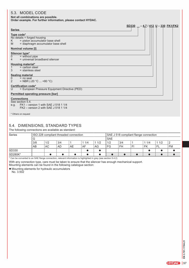
5.3. MODEL CODENot all combinations are possible. Order example. For further information, please contact HYDAC.
SD330 – 4,7 / 412 U – 330 FK1/FK2SeriesType code* No details = forged housing K = piston accumulator base shell M = diaphragm accumulator base shellNominal volume [l]Silencer type* 0 = without pipe 4 = universal broadband silencerHousing material* 1 = carbon steel 3 = stainless steelSealing material 0 = no seal 2 = NBR (-20 °C ... +80 °C)Certification code* U = European Pressure Equipment Directive (PED)Permitted operating pressure [bar]Connections See section 5.4. e.g. FK1 – version 1 with SAE J 518 1 1/4 FK2 – version 2 with SAE J 518 1 1/4
* Others on request
5.4. DIMENSIONS, STANDARD TYPESThe following connections are available as standard:
Series ISO 228 compliant threaded connection SAE J 518 compliant flange connectionG SAE3/8 1/2 3/4 1 1 1/4 1 1/2 1/2 3/4 1 1 1/4 1 1/2 2AB AC AD AE AF AG FG FH FI FK FL FM
SD330 z z z z zSD280K* z z z z z z z z z z z* Can be converted to an SAE flange connection, relevant information is highlighted in grey (see section 5.4.2)
With any connection type, care must be taken to ensure that the silencer has enough mechanical support. Mounting elements can be found in the following catalogue section:
zMounting elements for hydraulic accumulators No. 3.502

98
EN 3
.701
.17/
04.2
1
L A
L
G2
16
8
155
D
G2
420
A
D
D
420
F
G2
L1
D
F
L2
G2
16
8
155
5.4.1 SD330
SAE J 518 compliant flange connection F
Series Vol.
[l]
Perm. operating pressure[bar]
AISO 228
L
[mm]
D*
[mm]
Weight
[kg]
Part no.
SD330 4.7 330 AF/AF G 1 1/4 31 25 14.8 4390237AG/AG G 1 1/2 31 32 15.8 4388045
* Smallest internal diameter
Series Vol.
[l]
Perm. operating pressure[bar]
FSAE J 518
L2for FK2[mm]
L1for FK1[mm]
D*
[mm]
Weight
[kg]
Part no.
SD330 4.7 330
FK2/FK2 SAE 1 1/4 31 – 25 16.9 4413180FK1/FK2 SAE 1 1/4 31 76 25 15.9 4402764FL2/FL2 SAE 1 1/2 36 – 30 18.2 4390978FL1/FL2 SAE 1 1/2 36 76 30 16.8 4413183FM2/FM2 SAE 2 41 – 32 22 4413377FM1/FM2 SAE 2 41 93 32 19.2 4413381
* Smallest internal diameter
ISO 228 compliant threaded connection A
version 2e.g. FK2
version 1e.g. FK1
99
EN 3
.701
.17/
04.2
1
A
D2
A
D1
D1
L
A
L
SW
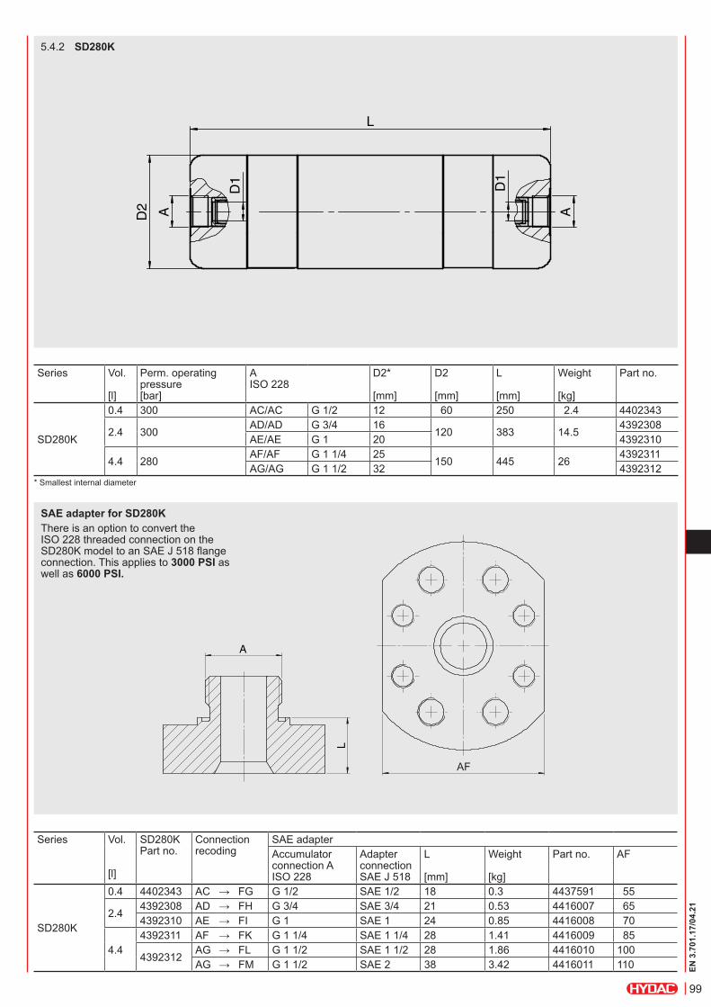
5.4.2 SD280K
Series Vol.
[l]
Perm. operating pressure[bar]
AISO 228
D2*
[mm]
D2
[mm]
L
[mm]
Weight
[kg]
Part no.
SD280K
0.4 300 AC/AC G 1/2 12 60 250 2.4 4402343
2.4 300 AD/AD G 3/4 16 120 383 14.5 4392308AE/AE G 1 20 4392310
4.4 280 AF/AF G 1 1/4 25 150 445 26 4392311AG/AG G 1 1/2 32 4392312
* Smallest internal diameter
Series Vol.
[l]
SD280KPart no.
Connection recoding
SAE adapterAccumulator connection A ISO 228
Adapter connectionSAE J 518
L
[mm]
Weight
[kg]
Part no. AF
SD280K
0.4 4402343 AC → FG G 1/2 SAE 1/2 18 0.3 4437591 55
2.4 4392308 AD → FH G 3/4 SAE 3/4 21 0.53 4416007 654392310 AE → FI G 1 SAE 1 24 0.85 4416008 70
4.44392311 AF → FK G 1 1/4 SAE 1 1/4 28 1.41 4416009 85
4392312 AG → FL G 1 1/2 SAE 1 1/2 28 1.86 4416010 100AG → FM G 1 1/2 SAE 2 38 3.42 4416011 110
SAE adapter for SD280KThere is an option to convert the ISO 228 threaded connection on the SD280K model to an SAE J 518 flange connection. This applies to 3000 PSI as well as 6000 PSI.
AF

100
EN 3
.701
.17/
04.2
1 HYDAC Technology GmbH Industriegebiet 66280 Sulzbach/Saar, Germany Tel.: 0049 (0) 68 97 / 509 - 01 Fax: 0049 (0) 68 97 / 509 - 464 Internet: www.hydac.com E-mail: [email protected]
6. NOTEThe information in this brochure relates to the operating conditions and fields of application described. For applications and/or operating conditions not described, please contact the relevant technical department. Subject to technical modifications.
5.5. SPARE PARTS AND ACCESSORIES5.5.1 Spare partsNBR, others on request
Designation Part no.Seal kit SD280K NBR 4416121
5.5.2 Mounting elementsThe following table lists the recommended mounting clamps. The choice of clamp depends on the external diameter of the silencer (for more information on mounting elements see section 5.4.).
Designation Part no. Series SD330 SD280K4.7 0.4 2.4 4.4
HyRac 167-175/178 H5 ST 445043 z
HRGKSM 0 R 58-61/62 ST 3018442 z
HRGKSM 1 R 119-127/124 ST 444505 z
HRGKSM 1 R 146-154/151 ST 444321 z