1 Cryogenic in Fusion Devices” Kavita Rathore MTech – NST Delhi University.
16
1 Cryogenic in Fusion Devices” Kavita Rathore MTech – NST Delhi University
-
Upload
clemence-crawford -
Category
Documents
-
view
219 -
download
0
Transcript of 1 Cryogenic in Fusion Devices” Kavita Rathore MTech – NST Delhi University.
1
Cryogenic in Fusion Devices”
Kavita RathoreMTech – NST
Delhi University

2
Outline
Role of Cryogenics in Fusion devices
Properties of material at Cryo Temperatures
Cryogenic Design aspects
Helium as magic fluid
Production, Storage and Transfer of cryogens
Cooling Method used in Tokomak
Safety issues related to cryogenics

3
Role of Cryogenics in Fusion devices
Superconducting Magnets, cryo pumping for NBI, Diverter, and Pellet injection / Fueling highly dependent on the Cryo technology.
GHz high power RF system uses Gyrotrons, operates with Cryogenics.
Cryogenics technology provides variety of operations at cold temperatures starting from sub-cooled superfluid, two-phase flow to forced flow supercritical Helium .
Higher capacity demands efficient and thermodynamic Exergy system to meet the economics of plug-power.
Cryo capacity varies from 1 kW – 100 kW at 4.5 K depending upon the machine size e.g. SST-1 has 1.3 kW whereas ITER has 70 kW @ 4.5 K

4
Where efficiency optimization lies?
Efficiency of commercial Fusion reactor depends on many factors:
- Plasma density, temperature and confinement time product yield
(The Lawson criterion: At T ≥ 108 K, n ≥ 1020 m-3s)
- Efficiency of auxiliary plasma heating schemes
- Advantage of recycled alpha- particles heating
- Overall input electrical power
One of the major power consuming device is LHe cryogenic plant
SST-1 India 1.3 kW at 4.5 K consumes electrical power: 0.7 MW
ITER, IT 72 kW at 4.4 K will consume electrical power: 16.5 MW
Demo power reactor 100 kW at 4.5 K will consume power: 23 MW

5
Properties of material at cryo Temperature
6
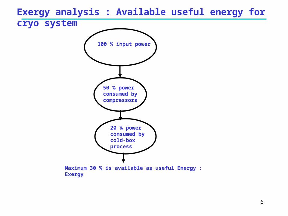
Exergy analysis : Available useful energy for cryo system
100 % input power
50 % power consumed by compressors
20 % power consumed by cold-box process
Maximum 30 % is available as useful Energy : Exergy

7
Different cooling options
Cooling using Sub-atmospheric Superfluid Helium (He- II) (Top < 2.17 K)
Tore Supra: The first SC Tokamak at 1. 8 K
Cooling using Pool Boiling Helium (He- I) (LHD Helical Coils)
Cooling using Two-phase flow Helium (He- I) (LHD supports and sc bus lines)
Cooling using Supercritical Helium (He- I) (SST-1, EAST, KSTAR, ITER)
Monolithic conductors design for TPC CICC of ITER TF Magnets

8
Supercritical Helium Vs Two-phase cooling for Magnets
He- I (Normal Helium): P: 1 bar and T ~ 4.2 K
He- II (Superfluid Helium): P < 1 bar and T < T
Two-phase Flow: From Pop of 1.0 bar – 2.3 bar and T_Saturation of Helium, the fluid exhibits Two-phase flow behavior when heat is added. In TP mode, temperature of He does not change but the quality () changes through Latent heat of vaporization.
Supercritical Helium:
P > Pc ~ 2.3 bar
Exhibits as dense cloud of mist
No Latent heat of vaporization
No Phase change
No Quality change

9
Cryo Forced flow cooled system: single phase Helium
Why supercritical Helium as coolant?After 1980’s, advanced superconductor technology for the Fusion grade machines adopted Cable – in – conduit – conductors (CICC) concept developed at MIT by Hoenig Montgomery.
The CICC concept has lot more merits with respect to Monolithic design but provides very complicated path for the coolant.
Looking at the safe and stable operation of such CICCs, the high pressure turbulent cooling system is desired.
Using SHe as Coolant:
Flow instabilities / chocking can be avoided
Higher heat transfer rates compared to TP
Top can be optimized over a wide range
Less pressure drop
Sudden thermal runaway can be avoided
Few Pros of TP cooling:
There is only little change in temperature of fluid till complete liquid is evaporated
Flow rate requirement is less compared to SHe cooling

10
Different ways to produce supercritical Helium
Supercritical Helium can be generated even without using cold circulator, the plant process is worked out that setting the outlet pressure of cold turbine, cold supercritical helium can be produced with limited mass flow rates at 4 bar / 4.5 K.
When the application load demands higher mass flow rates of Supercritical Helium then one has to use cold circulator with by-pass valve mechanism, Heat load of the circulator is dumped into the LHe buffer vessel and HEX is placed into the vessel to provide the stabilized temperature of the incoming stream.

11
Pre-requirement for switch over to SHe operation
Definition of Supercritical Helium:
Supercritical is a state where operation pressure is beyond critical pressure (i.e. 2.3 bar).
Supercritical state is clear single phase state.
The pressure drop of Supercritical liquid Phase is always less than that of Gas phase.
Temperature of Supercritical Fluid increases subjected to Heat loads.Pre-requirement for switch over from DP mode to Supercritical Helium:
[1] Plant Return Temperature as well as Load shall be less than 7.0 K
[2] The pressure drop across the load shall be less than 500 mbar at T < 7.0 K
[3] The load condition shall be stable in terms of (Pressure, Temperature and Flow)
[4] The total liquid filled in MCD shall be 800 L.
[5] The Sub-cooler Dewar level shall be filled up to 650 mm (HEX bath pool)
SST-1 HRL PFD

12
Forced flow cryo system in D-IIID Tokamak (Cryo pump)
Schaubel, K.M. Baxi, C.B. et al, IEEE Fusion Engineering, 1991
Simplified Cryogenic flow diagram in D-IIID tokamak for Diverter Cryo pumping
Application: Advanced Diverter cryo pump
Cryo pumping speed: 50,000 l/s
Cryo pump: Liquid Helium cooled tube at 4.3 K
Thermal shield: 80 K cooled with liquid Nitrogen
Compressed GHe is flowing through HEXs in HP side
Liquid Helium is collected in Dewar
(using J-T valve expansion)
LN2 LN2 forced flow cooling through the bulk storage
Cryo system Control using a dedicated PLC system
Diverter Cassata

13
Current leads and current feeders for Fusion devices
PowerSupply
4.5 K 300 K
JointTFCoil
S-bend
Dump Circuit
Joint
Water-cooled Al bus bar
Current lead partLTS feeder part
A superconductor current feeder system is required for
Current supply from power supply at 300K to the SC magnets at 4.5 K.
Safe extraction of the stored magnet energy during the quench.

14
Cryo Forced flow cooled system: single phase Nitrogen
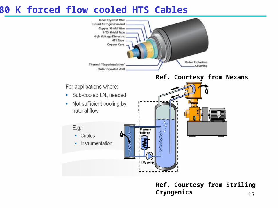
15
Ref. Courtesy from Striling Cryogenics
Ref. Courtesy from Nexans
80 K forced flow cooled HTS Cables

16
Outlook
Operation of the steady state fusion device demands forced flow cooling techniques for their Helium and Nitrogen Cryogenics systems.
Supercritical Helium provides better cryo stability than the Two-phase flow cooling particularly for the SC magnets system where flow channel paths are very complicated.
In any case, controlled cool-down philosophy obeys the procedure that first the load will be cooled using two-phase mode and once the desire temperature is achieved then only the single phase booster mode can be switched ON.
Future fusion machines need HTS based Engineering solutions to meet the economics of plug-power for current leads and feeders and still challenge would be large size magnets manufactured with HTS technology.
Reliable and proven booster machines are essential for cooling of the steady state forced flow cryogenic system