1 Configuration Overview. Agenda General RF setup Physical connections Review of front panel options...
32
1 Configuration Overview
-
Upload
mervyn-newman -
Category
Documents
-
view
220 -
download
1
Transcript of 1 Configuration Overview. Agenda General RF setup Physical connections Review of front panel options...

1
Configuration Overview

Agenda• General RF setup• Physical connections• Review of front panel options• Overview of Maestro configuration
2
General RF information• EU HD units output DVB-T by default, DVB-C also available
• DVB-T tuner is required• If HD signal is being sent the tuner must support HD video
• DVB-T requires a full RF channel (8MHz by default) for each video input• DVB-C uses a single RF channel (8MHz by default) for 2 video inputs
• HDb2380 (composite input) currently only outputs DVB-C
• RF power must be balanced with existing modulators or feeds
• RF output can be set between +45dBmV and +25dBmV• ZvPro defaults to +25dBmV• HDbridge2000 defaults to +45dBmV
• New to RF distribution – check out “Using Coaxial Cabling for Video Distribution” tutorial on our website• http://zeevee.com/support/training (Design & Installation tab)
3
STANDARD COAX
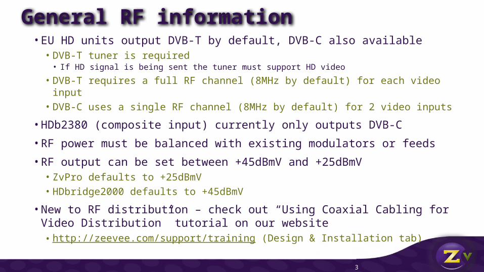
Modulated Channel with Existing Feed
ADVANTAGES OF BROADCASTING HD OVER COAX
• Adding a new channel to existing cable is simple – just use a splitter backwards!
• Adding another TV is simple – just use a simple coax splitter!
• Can upgrade or add channels one at a time – no need to do everything at once
SATELLITE RECEIVER, STB, CABLE BOX, COMPUTER OR DIGITAL SIGNAGE PLAYER
Modulator
EXISTING MODULATED, TERRESTRIAL OR CABLE FEED
DRIVE UNLIMITED DISPLAYS.
JUST TUNE IN YOUR NEW CHANNEL
“COMBINE” YOUR NEW CHANNEL
INTO THE EXISTING LINEUP
Ensure signal is balanced and there are no channel or
frequency conflicts
COAX OUTVIDEO IN
SIMPLE SPLITTER,
BACKWARDS!
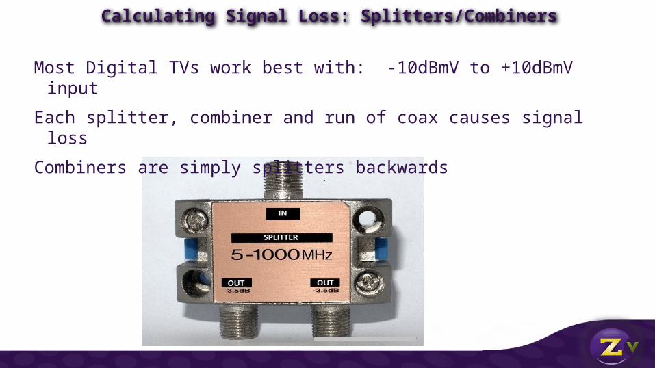
Calculating Signal Loss: Splitters/Combiners
Most Digital TVs work best with: -10dBmV to +10dBmV input
Each splitter, combiner and run of coax causes signal loss
Combiners are simply splitters backwards
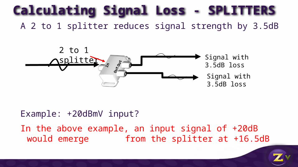
Calculating Signal Loss - SPLITTERSA 2 to 1 splitter reduces signal strength by 3.5dB
Example: +20dBmV input?
In the above example, an input signal of +20dB would emerge from the splitter at +16.5dB
2 to 1 splitter
Ou
t Ou
t
In
Signal with 3.5dB loss
Signal with 3.5dB loss
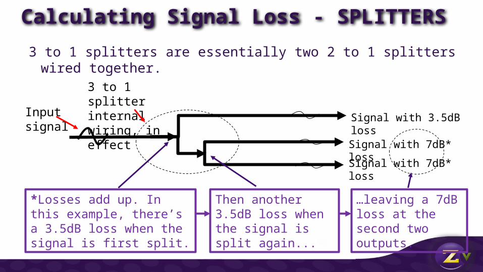
Calculating Signal Loss - SPLITTERS3 to 1 splitters are essentially two 2 to 1 splitters wired together.
3 to 1 splitter internal wiring, in effect
Signal with 3.5dB loss
Signal with 7dB* loss
Signal with 7dB* loss
Then another 3.5dB loss when the signal is split again...
*Losses add up. In this example, there’s a 3.5dB loss when the signal is first split.
…leaving a 7dB loss at the second two outputs.
Input signal
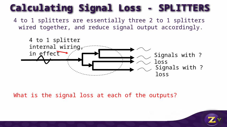
Calculating Signal Loss - SPLITTERS4 to 1 splitters are essentially three 2 to 1 splitters wired together, and reduce
signal output accordingly.
What is the signal loss at each of the outputs?
4 to 1 splitter internal wiring, in effect
Signals with ? loss
Signals with ? loss

Calculating Signal Loss - SPLITTERS4 to 1 splitters are essentially three 2 to 1 splitters wired together, and reduce signal output
accordingly.
ANSWER…. -7dB at each drop
4 to 1 splitter internal wiring, in effect
-7dB
-7dB-7dB
-7dB
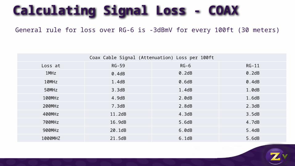
Calculating Signal Loss - COAX
Coax Cable Signal (Attenuation) Loss per 100ft
Loss at RG-59 RG-6 RG-11
1MHz 0.4dB 0.2dB 0.2dB
10MHz 1.4dB 0.6dB 0.4dB
50MHz 3.3dB 1.4dB 1.0dB
100MHz 4.9dB 2.0dB 1.6dB
200MHz 7.3dB 2.8dB 2.3dB
400MHz 11.2dB 4.3dB 3.5dB
700MHz 16.9dB 5.6dB 4.7dB
900MHz 20.1dB 6.0dB 5.4dB
1000MHZ 21.5dB 6.1dB 5.6dB
General rule for loss over RG-6 is -3dBmV for every 100ft (30 meters)
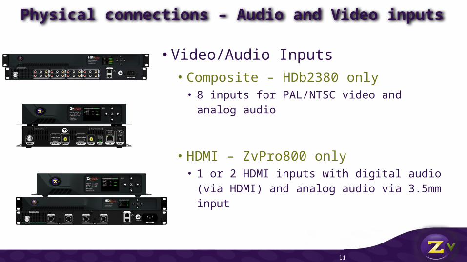
Physical connections – Audio and Video inputs
• Video/Audio Inputs• Composite – HDb2380 only
• 8 inputs for PAL/NTSC video and analog audio
• HDMI – ZvPro800 only• 1 or 2 HDMI inputs with digital audio (via HDMI)
and analog audio via 3.5mm input
11
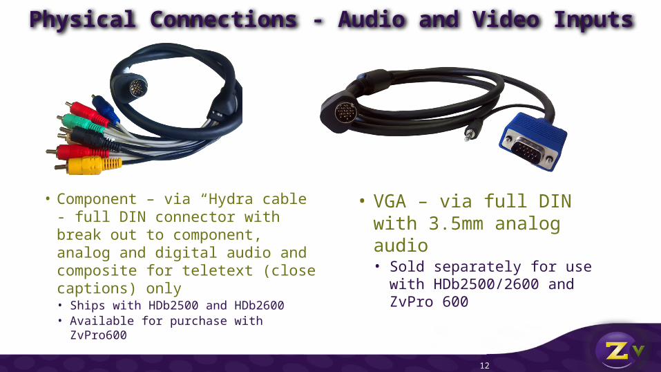
Physical Connections - Audio and Video Inputs
12
• Component – via “Hydra cable - full DIN connector with break out to component, analog and digital audio and composite for teletext (close captions) only • Ships with HDb2500 and HDb2600• Available for purchase with ZvPro600
• VGA – via full DIN with 3.5mm analog audio• Sold separately for use with
HDb2500/2600 and ZvPro 600
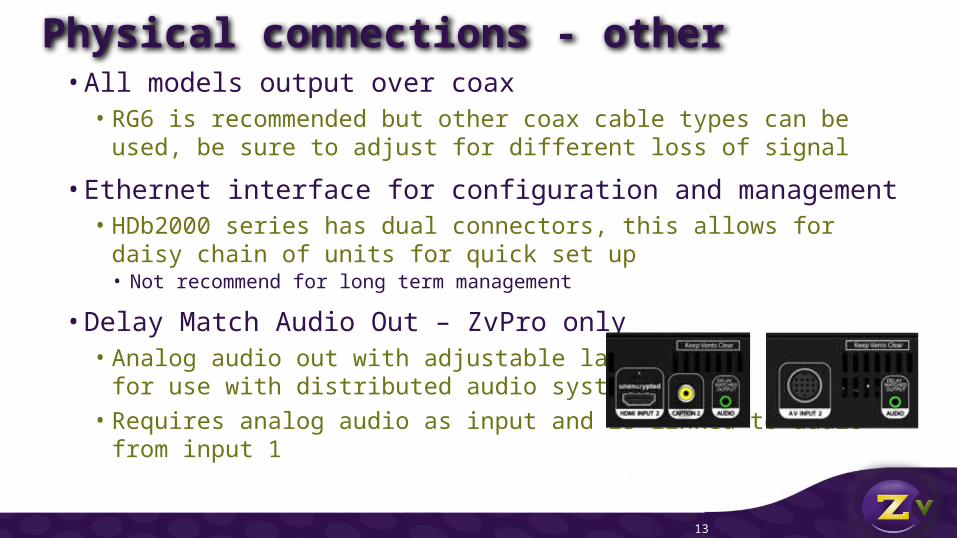
Physical connections - other • All models output over coax
• RG6 is recommended but other coax cable types can be used, be sure to adjust for different loss of signal
• Ethernet interface for configuration and management• HDb2000 series has dual connectors, this allows for daisy chain of
units for quick set up• Not recommend for long term management
• Delay Match Audio Out – ZvPro only• Analog audio out with adjustable latency
for use with distributed audio systems• Requires analog audio as input and is linked to audio from input 1
13
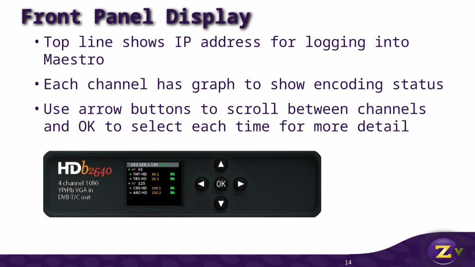
• Top line shows IP address for logging into Maestro
• Each channel has graph to show encoding status
• Use arrow buttons to scroll between channels and OK to select each time for more detail
Front Panel Display
14
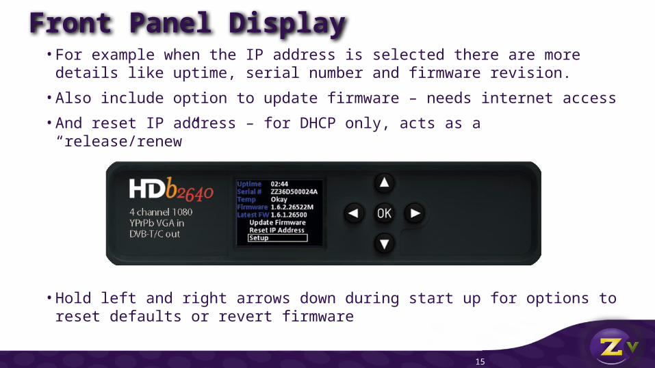
Front Panel Display• For example when the IP address is selected there are more details like
uptime, serial number and firmware revision.
• Also include option to update firmware – needs internet access
• And reset IP address – for DHCP only, acts as a “release/renew”
• Hold left and right arrows down during start up for options to reset defaults or revert firmware
15
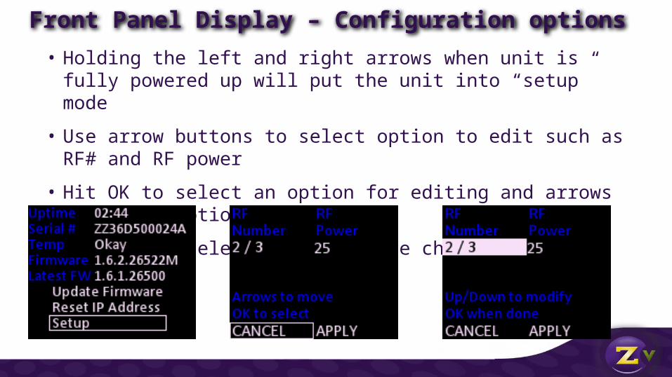
• Holding the left and right arrows when unit is fully powered up will put the unit into “setup” mode
• Use arrow buttons to select option to edit such as RF# and RF power
• Hit OK to select an option for editing and arrows to change options
• Be sure to select Apply to save changes
Front Panel Display – Configuration options
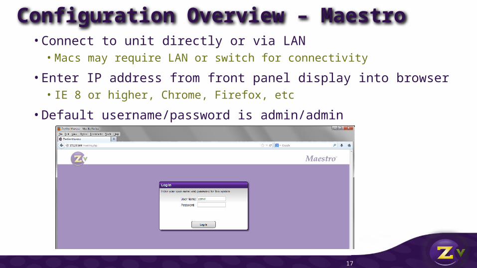
Configuration Overview – Maestro • Connect to unit directly or via LAN
• Macs may require LAN or switch for connectivity
• Enter IP address from front panel display into browser• IE 8 or higher, Chrome, Firefox, etc
• Default username/password is admin/admin
17

HDbridge 2000 Management – Status Tab
18
Tabs across top for configuration and management
General status information and warning messages

HDbridge 2000 Management – Status Tab
19
Button to manage all (note the message “1 connected 52 not connected” this shows 53 HDb2000/ZvPros found) on the network
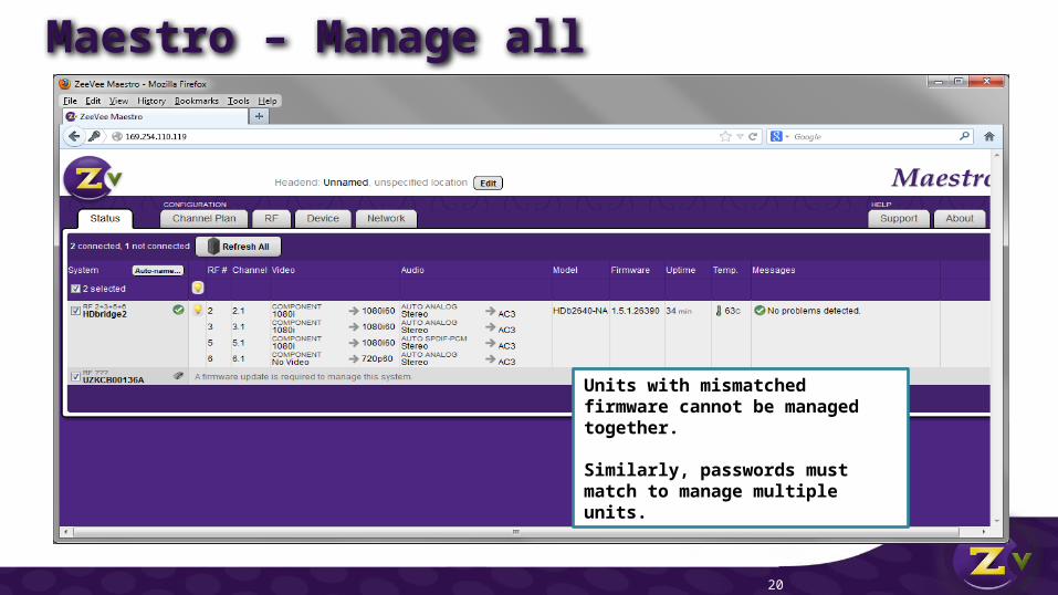
Maestro – Manage all
20
Units with mismatched firmware cannot be managed together.
Similarly, passwords must match to manage multiple units.
Maestro – Channel Plan
21
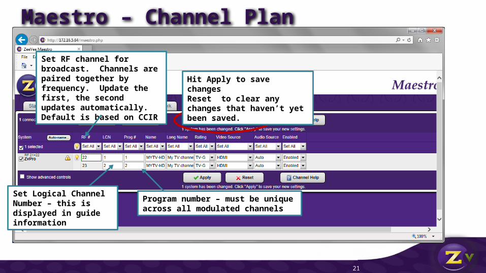
Set RF channel for broadcast. Channels are paired together by frequency. Update the first, the second updates automatically. Default is based on CCIR
Set Logical Channel Number – this is displayed in guide information
Program number – must be unique across all modulated channels
Hit Apply to save changesReset to clear any changes that haven’t yet been saved.
Maestro – Channel Plan
22
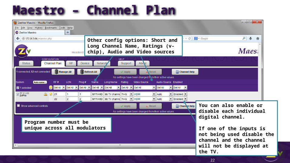
Program number must be unique across all modulators
Other config options: Short and Long Channel Name, Ratings (v-chip), Audio and Video sources
You can also enable or disable each individual digital channel.
If one of the inputs is not being used disable the channel and the channel will not be displayed at the TV.

Maestro – Channel Plan Advanced Options
23
Advanced control check box
STB channel allows for tracking information about the source in Maestro for consolidated location of information. This field is informational only.
Audio/Video delay options, allow for small adjustments to audio/video latency for lip sync purposes
Maestro – VGA settings
24
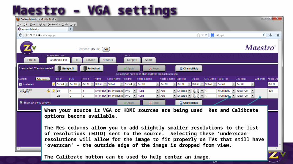
When your source is VGA or HDMI sources are being used Res and Calibrate options become available.
The Res columns allow you to add slightly smaller resolutions to the list of resolutions (EDID) sent to the source. Selecting these ‘underscan’ resolutions will allow for the image to fit properly on TVs that still have ‘overscan’ – the outside edge of the image is dropped from view.
The Calibrate button can be used to help center an image.
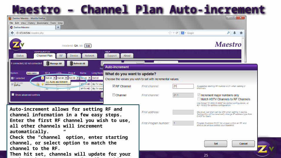
Maestro – Channel Plan Auto-increment
25
Auto-increment allows for setting RF and channel information in a few easy steps. Enter the first RF channel you wish to use, all other channels will increment automatically. Check the “channel” option, enter starting channel, or select option to match the channel to the RF. Then hit set, channels will update for your review, they are not saved until you hit “apply”
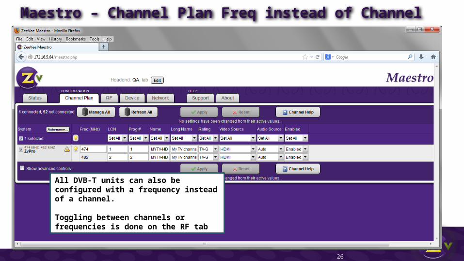
Maestro – Channel Plan Freq instead of Channel
26
All DVB-T units can also be configured with a frequency instead of a channel.
Toggling between channels or frequencies is done on the RF tab

Maestro – RF tab
27
Change RF between 45 and 25 dBmV. Channels must be with in 12dB of each other.
Turn full RF off. Broadcast for that channel will be stopped.
Change RF standard between DVB-T and DVB-C
Bandwidth defaults to 8MHz but can be changed to 7MHz to match regional requirements
Cable plan options are CCIR, None (enter frequency directly) and Australia others will be added with future firmware updates

Maestro – RF tab
28
Transport ID must be unique across all channels in a head end
Network and Original Network IDs are used in the data stream to ensure the channel information is displayed correctly by the TV tuner
3 letter country code
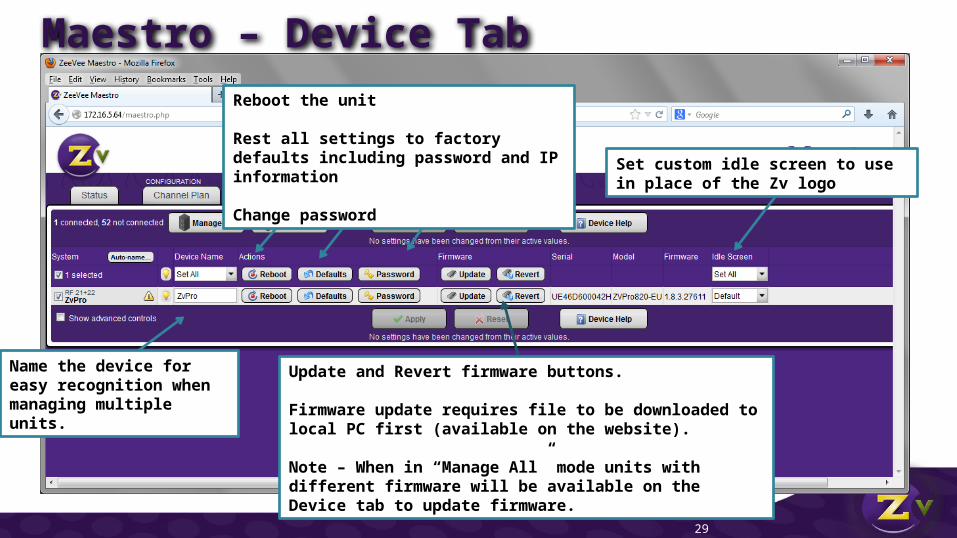
Maestro – Device Tab
29
Name the device for easy recognition when managing multiple units.
Update and Revert firmware buttons.
Firmware update requires file to be downloaded to local PC first (available on the website).
Note – When in “Manage All” mode units with different firmware will be available on the Device tab to update firmware.
Reboot the unit
Rest all settings to factory defaults including password and IP information
Change password
Set custom idle screen to use in place of the Zv logo
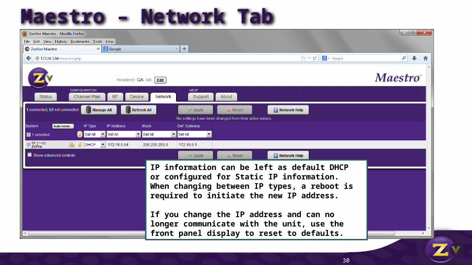
Maestro – Network Tab
30
IP information can be left as default DHCP or configured for Static IP information.When changing between IP types, a reboot is required to initiate the new IP address.
If you change the IP address and can no longer communicate with the unit, use the front panel display to reset to defaults.
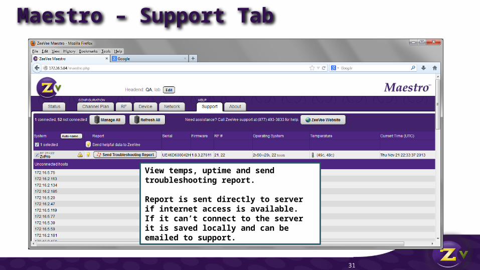
Maestro – Support Tab
31
View temps, uptime and send troubleshooting report.
Report is sent directly to server if internet access is available. If it can’t connect to the server it is saved locally and can be emailed to support.

Questions?ZeeVee Technical Support is there for
you!
877-493-3833
or
Zeevee.com/contact
32