1 COMS 361 Computer Organization Title: Instructions Date: 9/28/2004 Lecture Number: 10.
29
1 COMS 361 Computer Organization Title: Instructions Date: 9/28/2004 Lecture Number: 10
-
Upload
alina-pillow -
Category
Documents
-
view
213 -
download
0
Transcript of 1 COMS 361 Computer Organization Title: Instructions Date: 9/28/2004 Lecture Number: 10.

1
COMS 361Computer Organization
Title: Instructions
Date: 9/28/2004
Lecture Number: 10

2
Announcements
• Homework 4– Due 10/05/04

3
Review
• Instructions– unconditional branch– J-Type instruction format
• MIPS history
• SPIM– MIPS simulator

4
Outline
• SPIM– MIPS simulator

5
SPIM Program
• Show me the code!• MIPS/SPIM program files usually end in .s
• File is loaded into SPIM– Assembled into MIPS machine code– Executed and debugged in SPIM

6
SPIM Program## exit.s - program simply makes a system call to exit
#### text segment##
.text
main: addi $v0, $zero, 10 # exit call codesyscall # terminate program execution
#### data segment##
#### end exit.s

7
SPIM Program## exit.s - program simply makes a system call to exit
#### text segment##
.text
main: addi $v0, $zero, 10 # exit call codesyscall # terminate program execution
#### data segment##
#### end exit.s
Comments in MIPS assembly code are denoted by the sharp (#) sign
Similar to the C++ (//) comment. Starts at instance and goes to the end of the line
Assembly code in NOT self-documenting. Use comments liberally, like associated with each instruction

8
SPIM Program## exit.s - program simply makes a system call to exit
#### text segment##
.text
main: addi $v0, $zero, 10 # exit call codesyscall # terminate program execution
#### data segment##
#### end exit.s
Comments indicating the start of the code
After text segment is converted into its binary representation, it is stored in the text memory segment
. indicates an assembler directive
.text directs the assembler to treat what follows as instructions

9
Text Segment
• The source code format is relatively standard
– Proper indentation is fundamentally important in assembly language programming
– [] indicate optional fields• Not all fields appear on a line of code
[label:] operation [operand], [operand], [operand] [# comment]

10
SPIM Program## exit.s - program simply makes a system call to exit
#### text segment##
.text
main: addi $v0, $zero, 10 # exit call codesyscall # terminate program execution
#### data segment##
#### end exit.s
main: is a label
Just as C++ programs need a main function, MIPS programs need a main label
main: labels the first instruction of the program

11
Labels
• : – Tells the assembler that the proceeding
alphanumerics including (_) and (.) constitutes the label
– Opcodes are reserved words and are not permitted to be used as labels
– Use appropriate names for labels
• Labels associate a symbol with– The address of an instruction– The address of a variable

12
SPIM Program## exit.s - program simply makes a system call to exit
#### text segment##
.text
main: addi $v0, $zero, 10 # exit call codesyscall # terminate program execution
#### data segment##
#### end exit.s
Program is to simple call the OS with the exit call code
In the real world the OS cleans up after the program
The call code for exit is the decimal number 10, which needs to be put into the $v0 register (convention)
addi with the proper operands can achieve this goal

13
SPIM Program## exit.s - program simply makes a system call to exit
#### text segment##
.text
main: addi $v0, $zero, 10 # exit call codesyscall # terminate program execution
#### data segment##
#### end exit.s
Call the OS with the proper call code in the $v0 register

14
SPIM Program
• Show me the program execute!– And some things about SPIM City!!
• exit.s
• hello.s

15
Datapath Diagram
• Main functional units– Control unit Program Counter (PC)
Instruction Register
Register File
ALU
Cache Memory
Data In
Address
4
Out
Rs
RtRd
ControlLogic

16
Datapath Diagram
• Main functional units– Register file Program Counter (PC)
Instruction Register
Register File
ALU
Cache Memory
Data In
Address
4
Out
Rs
RtRd
ControlLogic

17
Datapath Diagram
• Main functional units– Arithmetic and logic unit (ALU) Program Counter (PC)
Instruction Register
Register File
ALU
Cache Memory
Data In
Address
4
Out
Rs
RtRd
ControlLogic

18
Datapath Diagram
• Main functional units– Program counter (PC) Program Counter (PC)
Instruction Register
Register File
ALU
Cache Memory
Data In
Address
4
Out
Rs
RtRd
ControlLogic

19
Datapath Diagram
• Main functional units– Memory Program Counter (PC)
Instruction Register
Register File
ALU
Cache Memory
Data In
Address
4
Out
Rs
RtRd
ControlLogic

20
Datapath Diagram
• Main functional units– Instruction register (IR) Program Counter (PC)
Instruction Register
Register File
ALU
Cache Memory
Data In
Address
4
Out
Rs
RtRd
ControlLogic

21
Datapath Diagram
• Other operational units– bus Program Counter (PC)
Instruction Register
Register File
ALU
Cache Memory
Data In
Address
4
Out
Rs
RtRd
ControlLogic

22
Datapath Diagram
• Other operational units– Multiplexor (data selector) Program Counter (PC)
Instruction Register
Register File
ALU
Cache Memory
Data In
Address
4
Out
Rs
RtRd
ControlLogic

23
Fetch and Execute R-type
• Instruction Fetch Phase– Fetch the word in memory at the address
specified by the Program Counter (PC)– Load instruction into the IR– Increment the PC (add 4)
• Operand Fetch Phase– Decode the Rs and Rt fields within the instruction
Decode the Op Code

24
Fetch and Execute Cycle
• Execute Phase– Perform ALU operation defined by the function
code on the source operands
• Write Back Phase– Result if the ALU is written into the decoded Rd
register

25
MIPS Instructions
• MIPS instruction set architecture– Assembly instructions that convert into machine
(binary) instructions• Assembly instructions can be converted directly into
machine instructions– One-to-one mapping
• Assembly instructions can be converted into more than one machine instruction
– One-to-many mapping
– Native machine instructions– Pseudo-, Macro-, Synthetic-machine instructions
• Consists of more than one native machine instruction

26
MIPS Instructions
• Assembler converts pseudo-instructions with the corresponding set of actual MIPS instructions– Pseudo-instructions simplify the task of writing
assembly code
pseudo instruction la $a0 label
load address of label into register $a0
actual MIPS instructions
lui $at, upper 16 bits of label
ori $Rd, $at, Lower 16 bits of label

27
Assembler Directives
• Used to create data structures that are available at run-time– To allocate a one-dimensional array in C++
int ARRAY[1024];
– Corresponds to the MIPS assemble directive
.data
ARRAY: .space 4096Allocate space in the data
segment of the SPIMmemory model
Allocates 4096 bytes in thedata segment
28
Assembler Directives
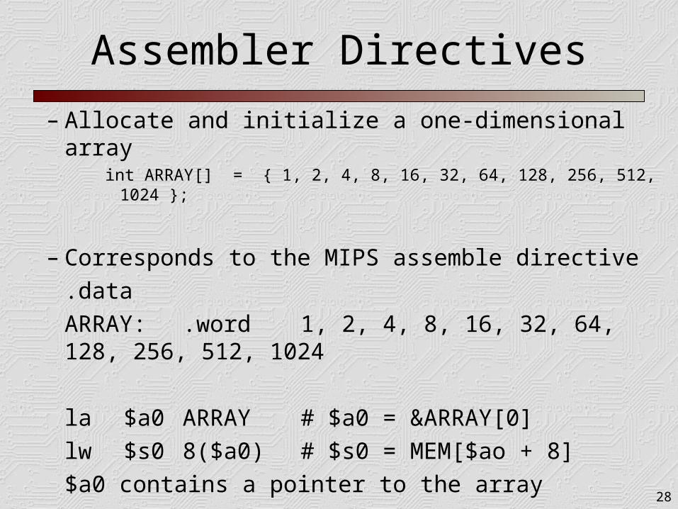
– Allocate and initialize a one-dimensional arrayint ARRAY[] = { 1, 2, 4, 8, 16, 32, 64, 128, 256, 512, 1024 };
– Corresponds to the MIPS assemble directive
.data
ARRAY: .word 1, 2, 4, 8, 16, 32, 64, 128, 256, 512,
1024
la $a0 ARRAY # $a0 = &ARRAY[0]
lw $s0 8($a0) # $s0 = MEM[$ao + 8]
$a0 contains a pointer to the array

29
Assembler Directives
– String literal definition
.data
helloStr: .ascii “Hello, World!\n”
– helloStr is the memory location of the array of characters
– The string is not null terminated• Can cause problems (hell01.s)
.data
helloStr: .asciiz “Hello, World!\n”