1 COMP541 Sequencing and Control Montek Singh Mar 29, 2007.
46
1 COMP541 COMP541 Sequencing and Control Sequencing and Control Montek Singh Montek Singh Mar 29, 2007 Mar 29, 2007
-
date post
20-Dec-2015 -
Category
Documents
-
view
221 -
download
1
Transcript of 1 COMP541 Sequencing and Control Montek Singh Mar 29, 2007.
1
COMP541COMP541
Sequencing and ControlSequencing and Control
Montek SinghMontek Singh
Mar 29, 2007Mar 29, 2007
2
TopicsTopics Starting on Chapter 8Starting on Chapter 8 Control unitControl unit
Multiplier as example Multiplier as example
Today: hardwired controlToday: hardwired control Next time: microprogrammed controlNext time: microprogrammed control
3
Control UnitsControl Units Two typesTwo types
ProgrammableProgrammable Non-programmable (what you are implementing)Non-programmable (what you are implementing)
Look at non-programmable firstLook at non-programmable first A multiplierA multiplier
4
Algorithmic State MachinesAlgorithmic State Machines Like a flowchart to express hardware Like a flowchart to express hardware
algorithmsalgorithms ASM describes sequence of events and timing ASM describes sequence of events and timing
relationshipsrelationships
Can then turn automatically into circuitCan then turn automatically into circuit
5
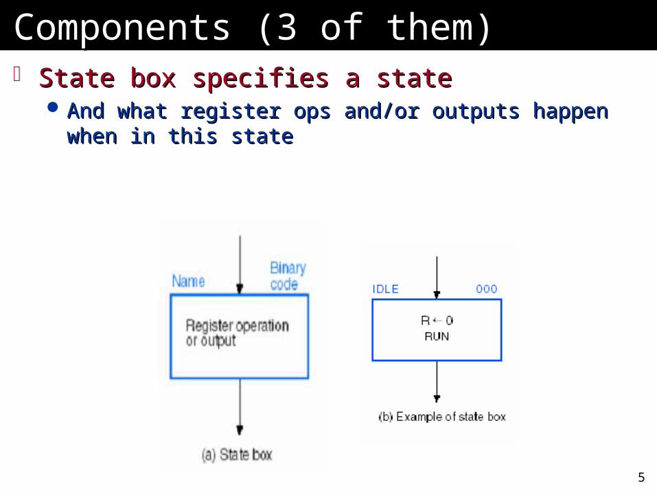
Components (3 of them)Components (3 of them) State box specifies a stateState box specifies a state
And what register ops and/or outputs happen when in And what register ops and/or outputs happen when in this statethis state
6
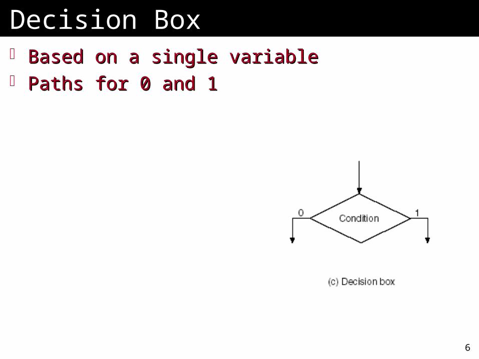
Decision BoxDecision Box Based on a single variableBased on a single variable Paths for 0 and 1Paths for 0 and 1
7
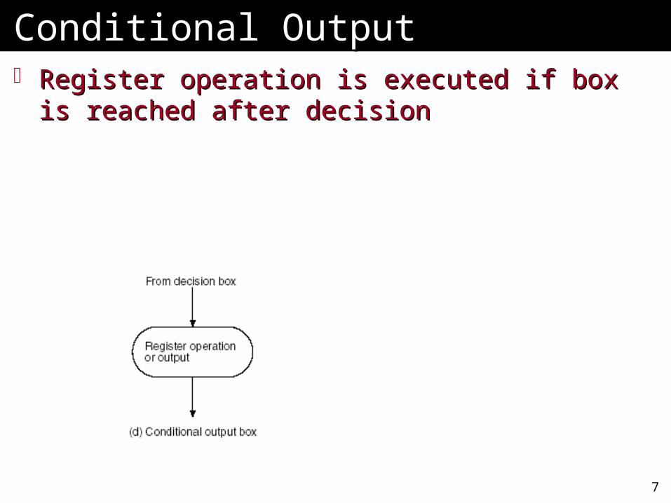
Conditional OutputConditional Output Register operation is executed if box is Register operation is executed if box is
reached after decisionreached after decision
8
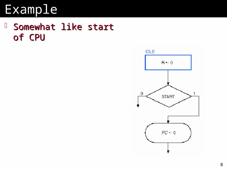
ExampleExample Somewhat like start of Somewhat like start of
CPUCPU
9
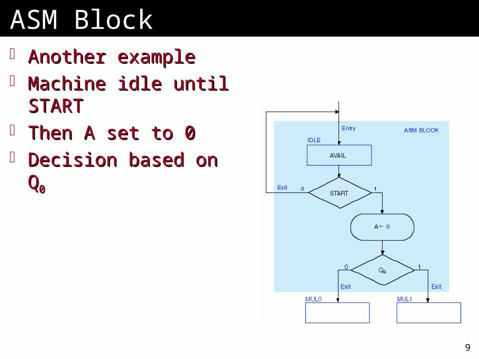
ASM BlockASM Block Another exampleAnother example Machine idle until Machine idle until
STARTSTART Then A set to 0Then A set to 0 Decision based on QDecision based on Q00
10
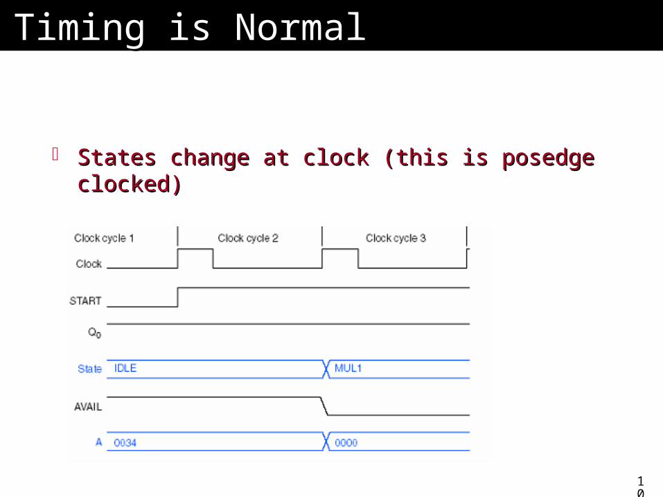
Timing is NormalTiming is Normal
States change at clock (this is posedge States change at clock (this is posedge clocked)clocked)
11
Example: Binary MultiplierExample: Binary Multiplier Two versionsTwo versions
Hardwired controlHardwired control MicroprogrammedMicroprogrammed
Multiplies two unsigned binary numbersMultiplies two unsigned binary numbers
12
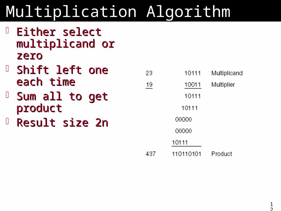
Multiplication AlgorithmMultiplication Algorithm Either select Either select
multiplicand or zeromultiplicand or zero Shift left one each Shift left one each
timetime Sum all to get Sum all to get
productproduct Result size 2nResult size 2n
13
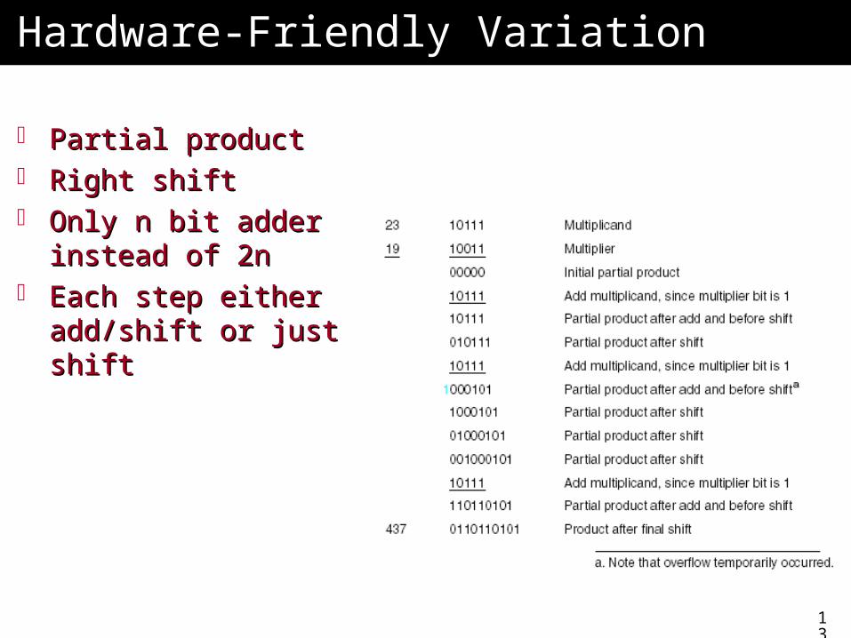
Hardware-Friendly VariationHardware-Friendly Variation
Partial productPartial product Right shiftRight shift Only n bit adder Only n bit adder
instead of 2ninstead of 2n Each step either Each step either
add/shift or just shiftadd/shift or just shift
14
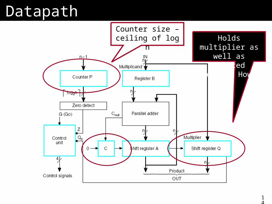
DatapathDatapathCounter size – ceiling of log n Holds multiplier as
well as shifted result. How?
15
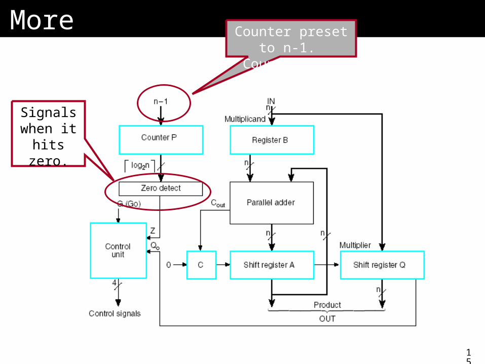
MoreMore Counter preset to n-1. Counts down.
Signals when it
hits zero.
16
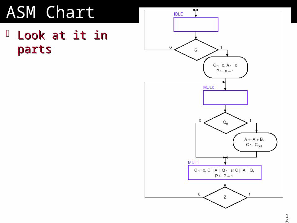
ASM ChartASM Chart Look at it in partsLook at it in parts
17
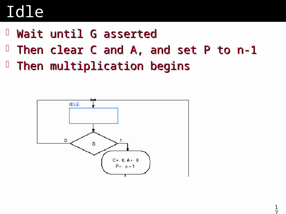
IdleIdle Wait until G assertedWait until G asserted Then clear C and A, and set P to n-1Then clear C and A, and set P to n-1 Then multiplication beginsThen multiplication begins
18
MultiplicationMultiplication
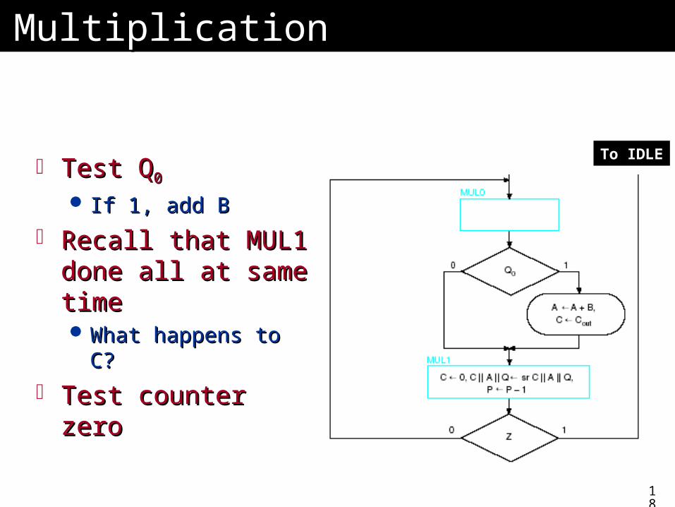
Test QTest Q00
If 1, add BIf 1, add B
Recall that MUL1 Recall that MUL1 done all at same done all at same timetime What happens to C?What happens to C?
Test counter zeroTest counter zero
To IDLE
19
Hardwired ControlHardwired ControlTwo aspects to controlTwo aspects to control
1.1. Control of the microoperationsControl of the microoperations• Generating signals, such as those for the ALU Generating signals, such as those for the ALU
operations, register numbers, etc.operations, register numbers, etc.
2.2. SequencingSequencing• What happens next?What happens next?• The order of any microoperationsThe order of any microoperations• Like states of our locksLike states of our locks
20
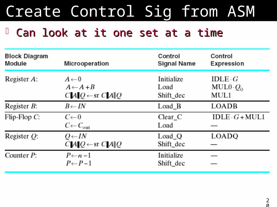
Create Control Sig from ASMCreate Control Sig from ASM Can look at it one set at a timeCan look at it one set at a time
21
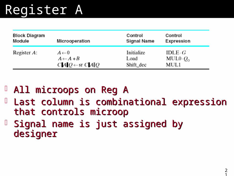
Register ARegister A
All microops on Reg AAll microops on Reg A Last column is combinational expression that Last column is combinational expression that
controls microopcontrols microop Signal name is just assigned by designerSignal name is just assigned by designer
22
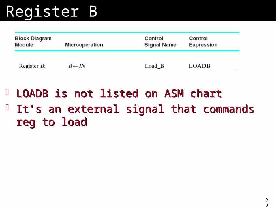
Register BRegister B
LOADB is not listed on ASM chartLOADB is not listed on ASM chart It’s an external signal that commands reg to It’s an external signal that commands reg to
loadload
23
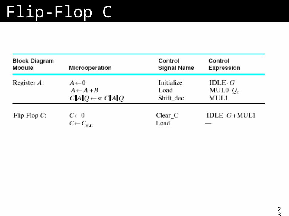
Flip-Flop CFlip-Flop C
24
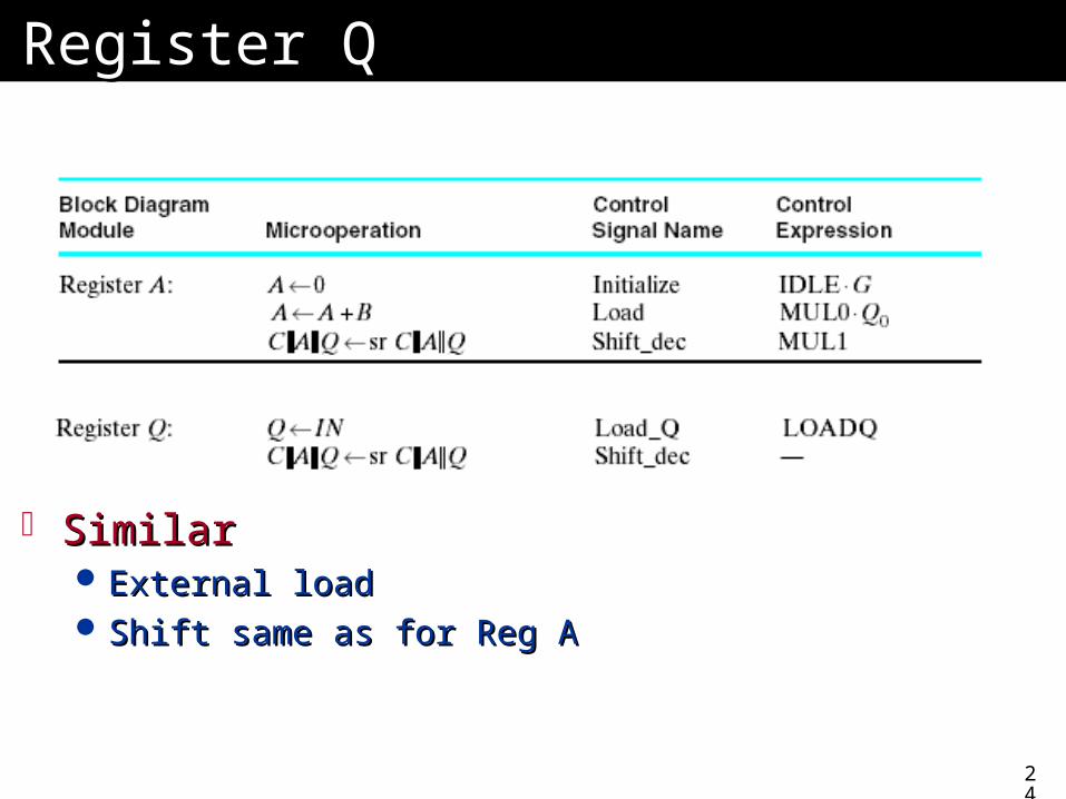
Register QRegister Q
SimilarSimilar External loadExternal load Shift same as for Reg AShift same as for Reg A
25
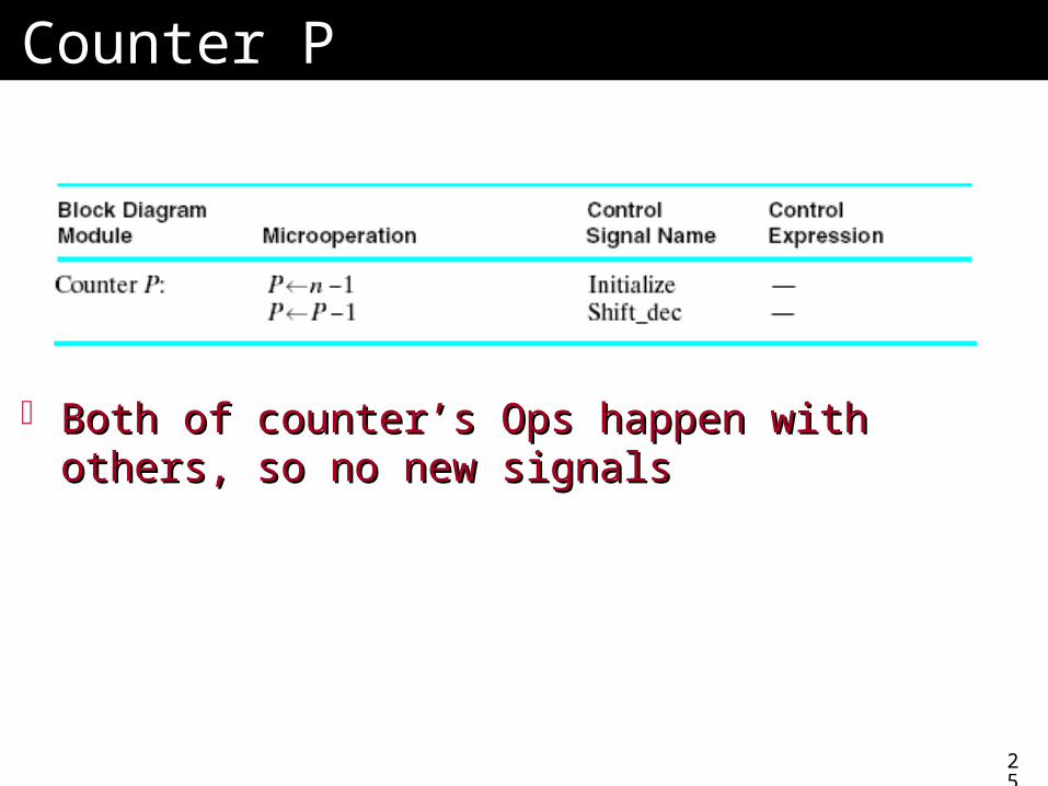
Counter PCounter P
Both of counter’s Ops happen with others, so Both of counter’s Ops happen with others, so no new signalsno new signals
26
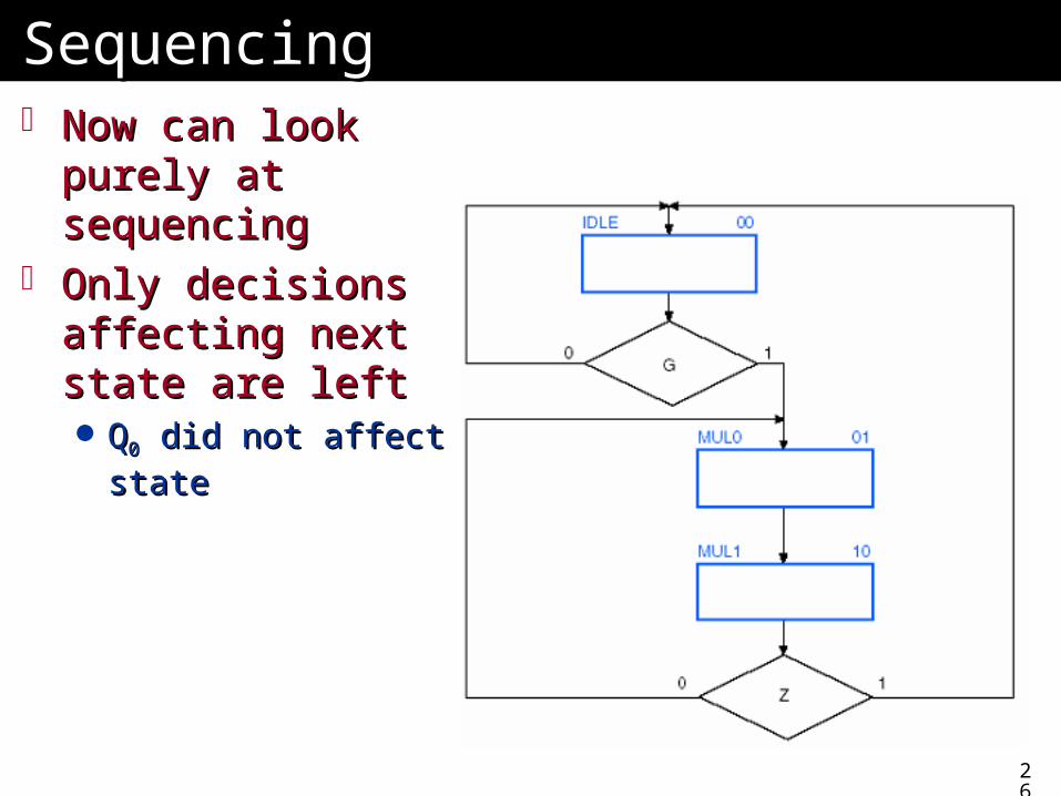
SequencingSequencing Now can look Now can look
purely at purely at sequencingsequencing
Only decisions Only decisions affecting next state affecting next state are leftare left QQ00 did not affect did not affect
statestate
27
Have State DiagramHave State Diagram This should look familiarThis should look familiar Similar to state diagram, such as used in your Similar to state diagram, such as used in your
lockslocks
We’ll look at manual design briefly, then We’ll look at manual design briefly, then VerilogVerilog
28
What We Need to DoWhat We Need to Do Have decided how to generate control signalsHave decided how to generate control signals Have separated control of timingHave separated control of timing
Now: implement in logicNow: implement in logic
29
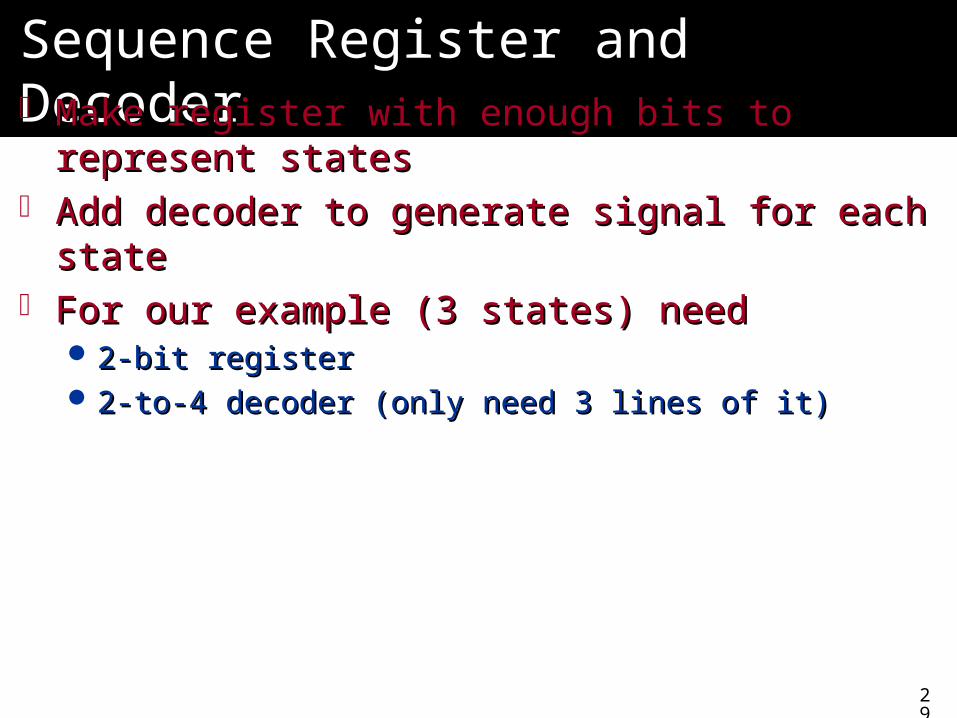
Sequence Register and DecoderSequence Register and Decoder Make register with enough bits to represent Make register with enough bits to represent
statesstates Add decoder to generate signal for each stateAdd decoder to generate signal for each state For our example (3 states) needFor our example (3 states) need
2-bit register2-bit register 2-to-4 decoder (only need 3 lines of it)2-to-4 decoder (only need 3 lines of it)
30
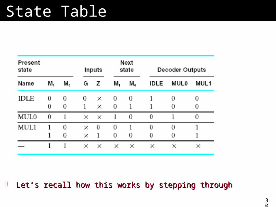
State TableState Table
Let’s recall how this works by stepping throughLet’s recall how this works by stepping through
31
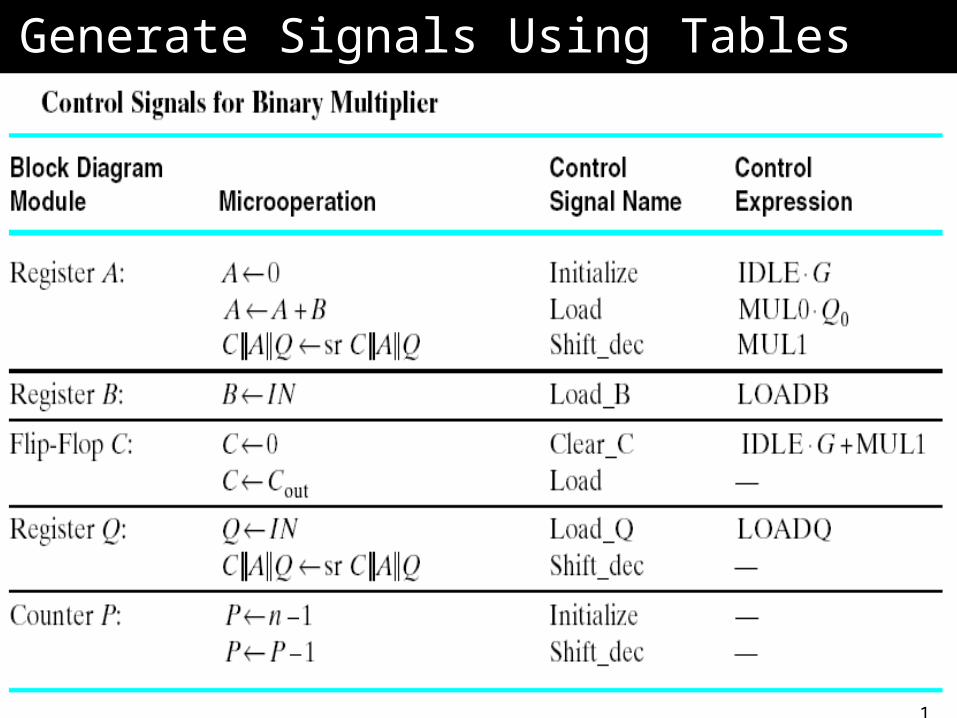
Generate Signals Using TablesGenerate Signals Using Tables
32
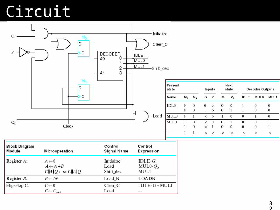
CircuitCircuit
33
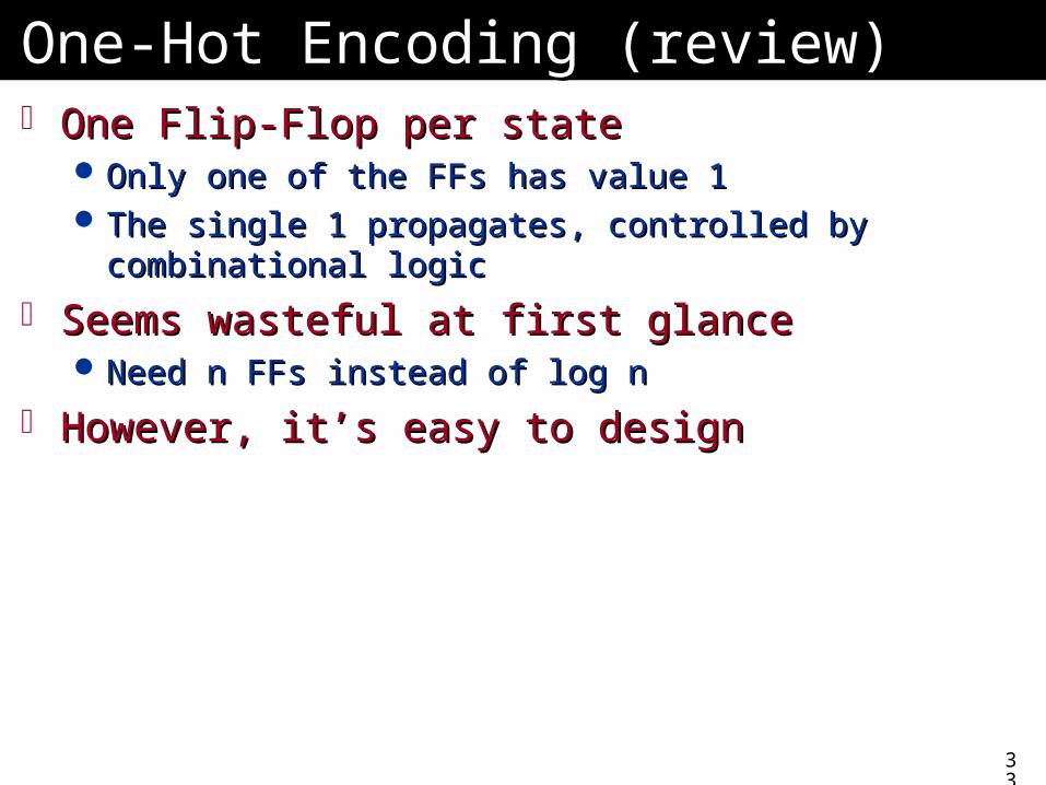
One-Hot Encoding (review)One-Hot Encoding (review) One Flip-Flop per stateOne Flip-Flop per state
Only one of the FFs has value 1Only one of the FFs has value 1 The single 1 propagates, controlled by combinational The single 1 propagates, controlled by combinational
logiclogic
Seems wasteful at first glanceSeems wasteful at first glance Need n FFs instead of log nNeed n FFs instead of log n
However, it’s easy to designHowever, it’s easy to design
34
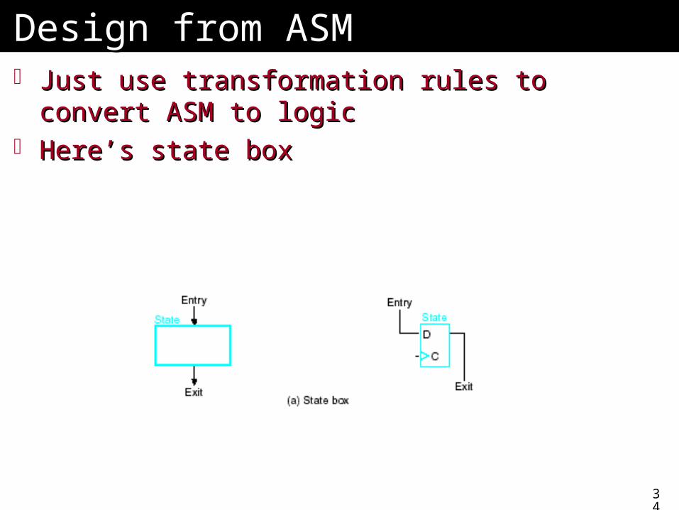
Design from ASMDesign from ASM Just use transformation rules to convert ASM to Just use transformation rules to convert ASM to
logiclogic Here’s state boxHere’s state box
35
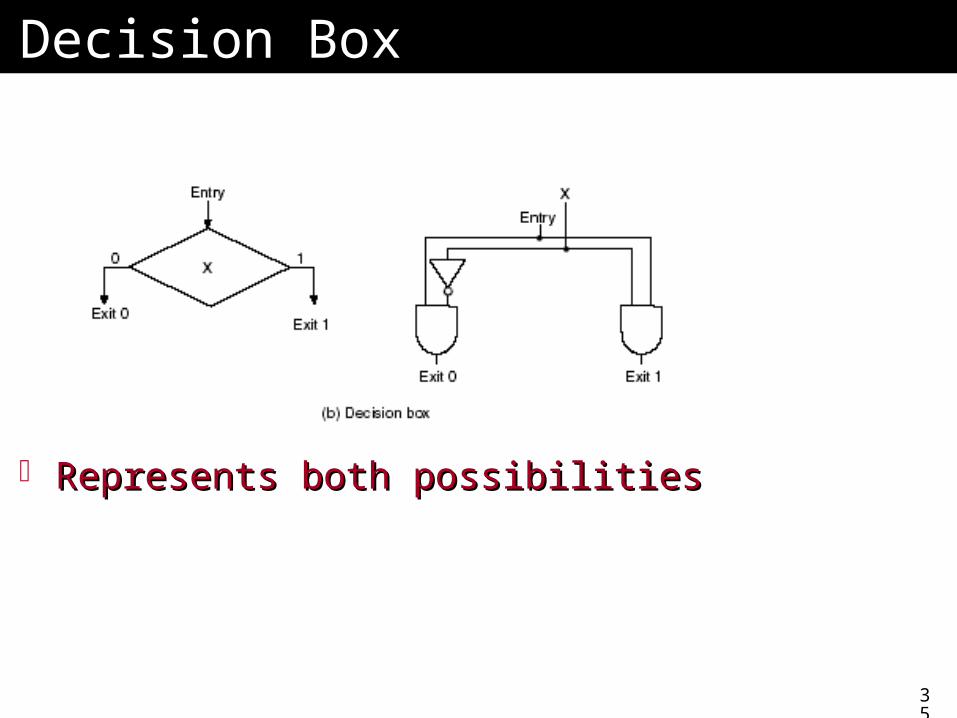
Decision BoxDecision Box
Represents both possibilitiesRepresents both possibilities
36
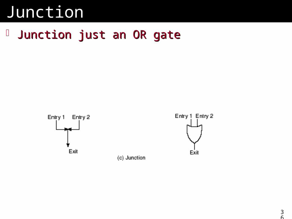
JunctionJunction Junction just an OR gateJunction just an OR gate
37
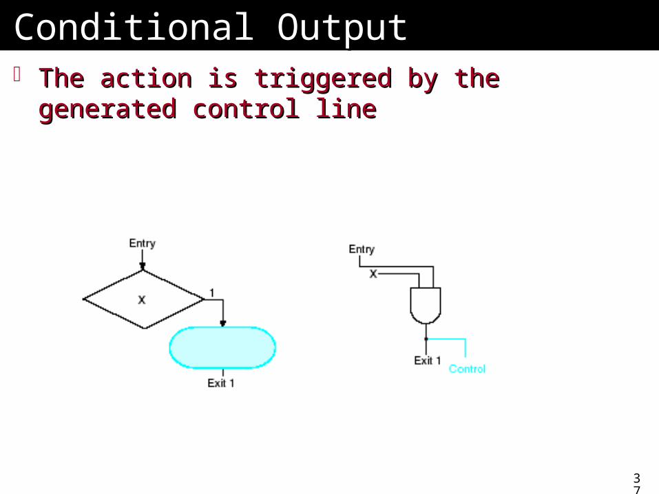
Conditional OutputConditional Output The action is triggered by the generated The action is triggered by the generated
control linecontrol line
38
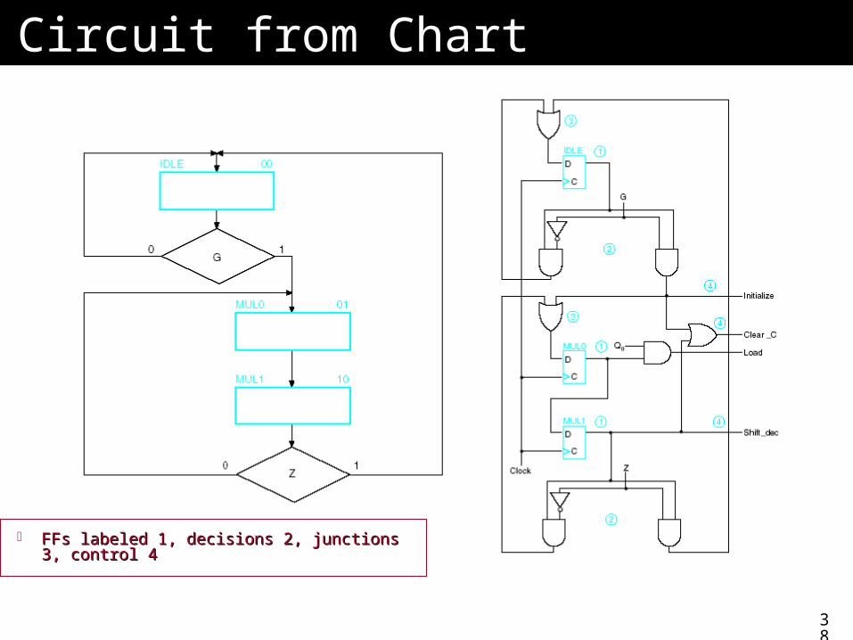
Circuit from ChartCircuit from Chart
FFs labeled 1, decisions 2, junctions 3, FFs labeled 1, decisions 2, junctions 3, control 4control 4
39
Verilog VersionVerilog Version Similar to the digital lockSimilar to the digital lock Case statement for sequence of statesCase statement for sequence of states
Transition to next state if criteria are trueTransition to next state if criteria are true
40
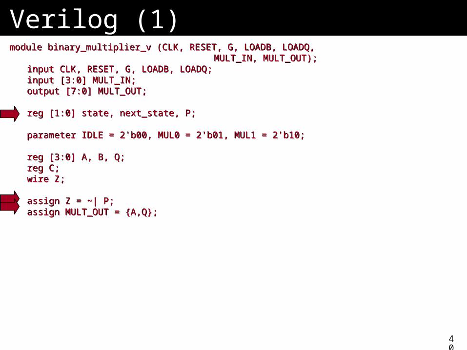
Verilog (1)Verilog (1)module binary_multiplier_v (CLK, RESET, G, LOADB, LOADQ, module binary_multiplier_v (CLK, RESET, G, LOADB, LOADQ,
MULT_IN, MULT_OUT);MULT_IN, MULT_OUT);input CLK, RESET, G, LOADB, LOADQ;input CLK, RESET, G, LOADB, LOADQ;input [3:0] MULT_IN;input [3:0] MULT_IN;output [7:0] MULT_OUT;output [7:0] MULT_OUT;
reg [1:0] state, next_state, P;reg [1:0] state, next_state, P;
parameter IDLE = 2'b00, MUL0 = 2'b01, MUL1 = 2'b10;parameter IDLE = 2'b00, MUL0 = 2'b01, MUL1 = 2'b10;
reg [3:0] A, B, Q;reg [3:0] A, B, Q;reg C;reg C;wire Z;wire Z;
assign Z = ~| P;assign Z = ~| P;assign MULT_OUT = {A,Q};assign MULT_OUT = {A,Q};
41
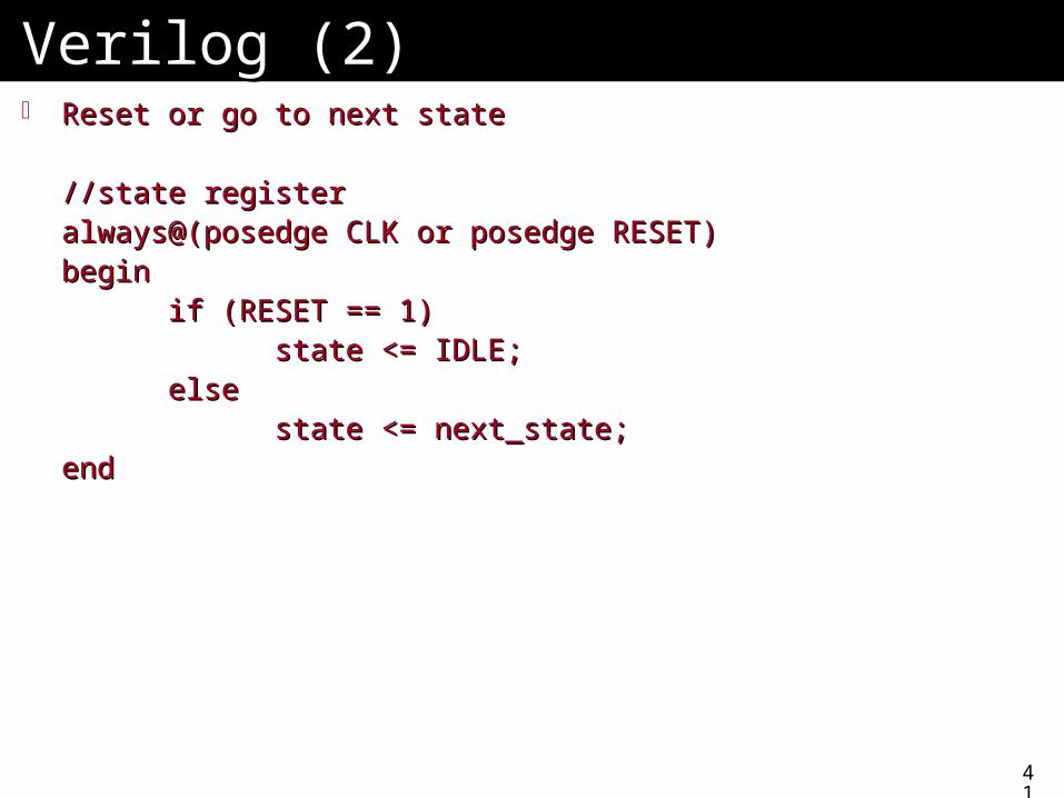
Verilog (2)Verilog (2) Reset or go to next stateReset or go to next state
//state register//state registeralways@(posedge CLK or posedge RESET)always@(posedge CLK or posedge RESET)beginbegin
if (RESET == 1)if (RESET == 1)state <= IDLE;state <= IDLE;
elseelsestate <= next_state;state <= next_state;
endend
42
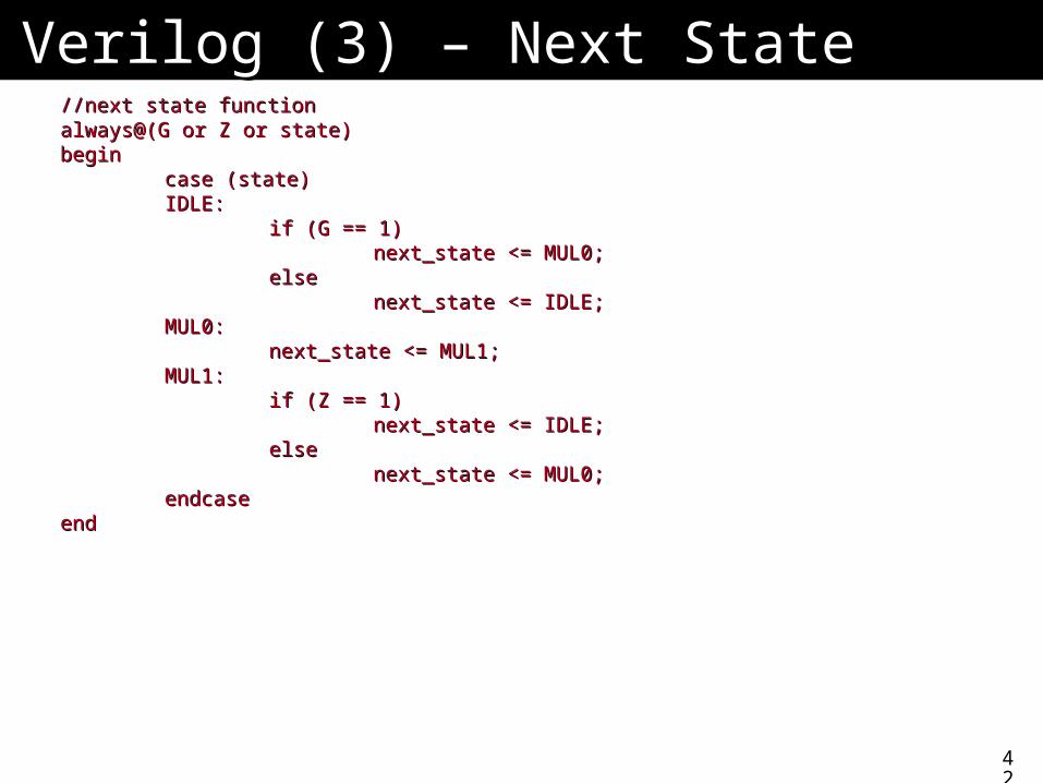
Verilog (3) – Next StateVerilog (3) – Next State//next state function//next state functionalways@(G or Z or state)always@(G or Z or state)beginbegin
case (state)case (state)IDLE:IDLE:
if (G == 1)if (G == 1)next_state <= MUL0;next_state <= MUL0;
elseelsenext_state <= IDLE;next_state <= IDLE;
MUL0:MUL0:next_state <= MUL1;next_state <= MUL1;
MUL1:MUL1:if (Z == 1)if (Z == 1)
next_state <= IDLE;next_state <= IDLE;elseelse
next_state <= MUL0;next_state <= MUL0;endcaseendcase
endend
43
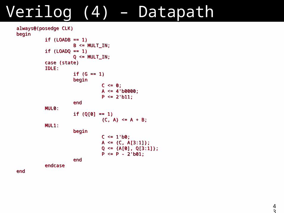
Verilog (4) – DatapathVerilog (4) – Datapathalways@(posedge CLK)always@(posedge CLK)beginbegin
if (LOADB == 1)if (LOADB == 1)B <= MULT_IN;B <= MULT_IN;
if (LOADQ == 1)if (LOADQ == 1)Q <= MULT_IN;Q <= MULT_IN;
case (state)case (state)IDLE:IDLE:
if (G == 1)if (G == 1)beginbegin
C <= 0;C <= 0;A <= 4'b0000;A <= 4'b0000;P <= 2'b11;P <= 2'b11;
endendMUL0:MUL0:
if (Q[0] == 1)if (Q[0] == 1){C, A} <= A + B;{C, A} <= A + B;
MUL1:MUL1:beginbegin
C <= 1'b0;C <= 1'b0;A <= {C, A[3:1]};A <= {C, A[3:1]};Q <= {A[0], Q[3:1]};Q <= {A[0], Q[3:1]};P <= P - 2'b01;P <= P - 2'b01;
endendendcaseendcase
endend
44
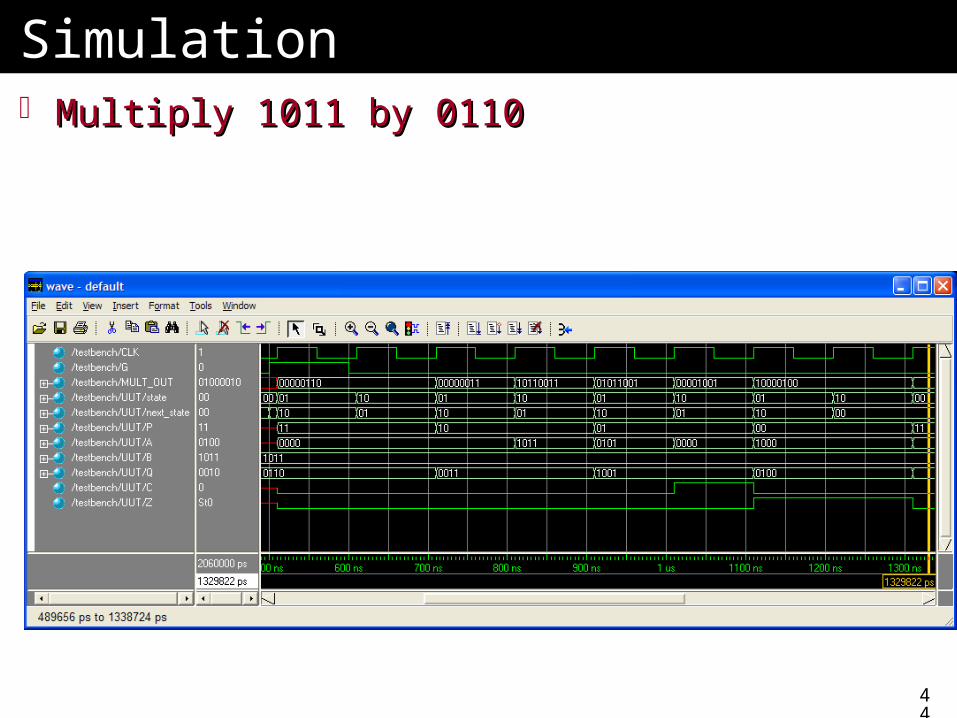
SimulationSimulation Multiply 1011 by 0110Multiply 1011 by 0110
45
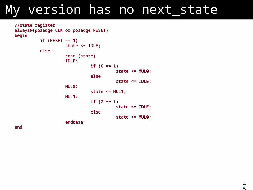
My version has no next_stateMy version has no next_state//state register//state registeralways@(posedge CLK or posedge RESET)always@(posedge CLK or posedge RESET)beginbegin
if (RESET == 1)if (RESET == 1)state <= IDLE;state <= IDLE;
elseelsecase (state)case (state)IDLE:IDLE:
if (G == 1)if (G == 1)state <= MUL0;state <= MUL0;
elseelsestate <= IDLE;state <= IDLE;
MUL0:MUL0:state <= MUL1;state <= MUL1;
MUL1:MUL1:if (Z == 1)if (Z == 1)
state <= IDLE;state <= IDLE;elseelse
state <= MUL0;state <= MUL0;endcaseendcase
endend
46
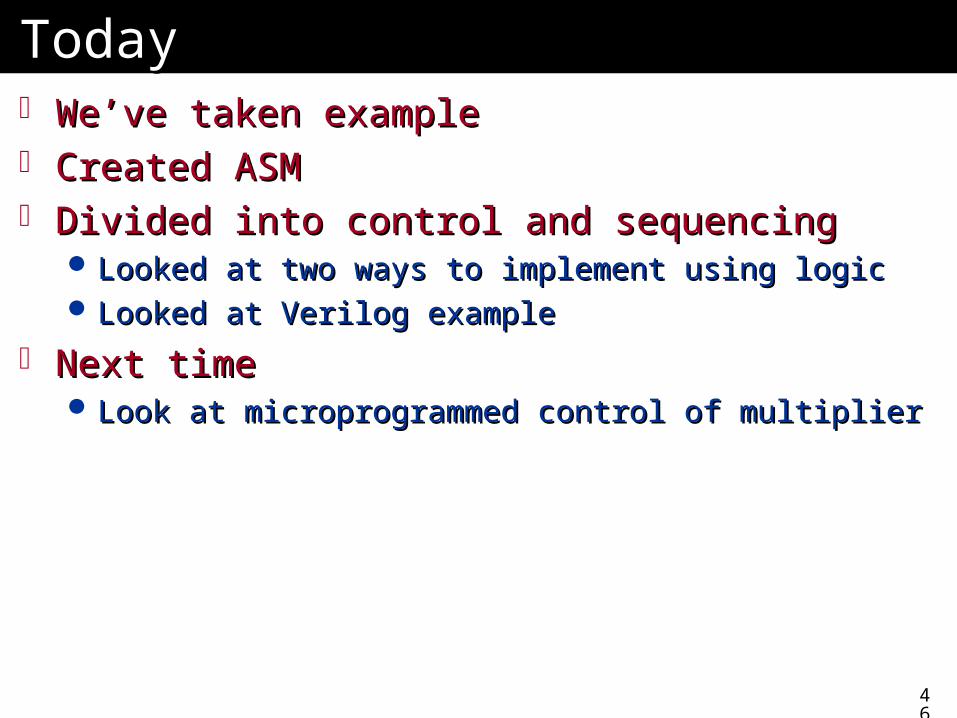
TodayToday We’ve taken exampleWe’ve taken example Created ASMCreated ASM Divided into control and sequencingDivided into control and sequencing
Looked at two ways to implement using logicLooked at two ways to implement using logic Looked at Verilog exampleLooked at Verilog example
Next timeNext time Look at microprogrammed control of multiplierLook at microprogrammed control of multiplier