
1 Chassis
61
USER MANUAL B. Chassis
-
Upload
rodrigo-bob -
Category
Documents
-
view
61 -
download
1
Transcript of 1 Chassis

USER MANUAL
B. Chassis

Release 6.0 / 2010
B-2
INDEX
1.CHASSIS ........................................................................................................... 4
GENERAL AGREEMENT AND WARRANTY............................................................ 5 FIXED PARTS .................................................................................................. 5
SAFETY WHEEL TETHERS ..................................................................................... 6
SET-UP.............................................................................................................. 7 MICHELIN TIRE INFORMATION .......................................................................... 7 SUGGESTED SETUP.......................................................................................... 7 SETUP ADJUSTMENT ........................................................................................ 8 SETTING THE VERTICAL SPRING PRE-LOAD......................................................... 9 FRONT ANTI ROLL DEVICE AND ROLL PRELOAD ................................................. 10 BELLEVILLE STACK CONFIGURATIONS.............................................................. 11 SETTING THE FRONT ROLL PRELOAD................................................................ 12 CASTOR ....................................................................................................... 13 FRONT SUSPENSION PICK-UP POINTS .............................................................. 14
STEERING WHEEL: .......................................................................................... 15 STEERING ASSEMBLY..................................................................................... 15 STEERING WHEEL HEIGHT .............................................................................. 16
REAR SUSPENSION ......................................................................................... 18 ROLL CENTER AND ANTISQUAT OPTIONS.......................................................... 18 FLOOR EXTENSION MODIFICATION .................................................................. 20 FLOOR EXTENSION MODIFICATION .................................................................. 21 REAR ANTIROLL BAR STIFFNESS...................................................................... 22 REAR SUSPENSION PICK-UP POINTS ................................................................ 24
SET-UP............................................................................................................ 25 RIDE HEIGHT CHECK AND REFERENCES............................................................ 25 DRAWINGS................................................................................................... 26
NOSE FITTING ................................................................................................ 29
AERODYNAMICS.............................................................................................. 30 DEFINITIONS ................................................................................................ 30 AERODYNAMICS FEATURES OF THE CAR ........................................................... 30 FRONT WING ASSEMBLY................................................................................. 31 MAIN BODY AND UNDERWING......................................................................... 34 REAR WING ASSEMBLY................................................................................... 36 LOW DOWNFORCE AERODYNAMIC CONFIGURATION (LAC) .................................. 42 POLAR DIAGRAM OF THE CAR.......................................................................... 43 AERO MAPS .................................................................................................. 44 COOLING INLET BLANKING ............................................................................. 46 POLAR DIAGRAM OF THE MAIN ADJUSTABLE DEVICES........................................ 47
OIL SYSTEM .................................................................................................... 48 OIL LEVEL AND CHARACTERISTICS .................................................................. 48
HYDRAULIC OIL SYSTEM................................................................................. 49
ENGINE COMPARTMENT COOLING .................................................................. 50
EXTRACTABLE SEAT ........................................................................................ 52 CARBON SHELL AND LEG STRAP POSITION ....................................................... 52

Release 6.0 / 2010
B-3
BLACK SOCKET POSITION............................................................................... 54 SIDE BELTS .................................................................................................. 54 DRIVER SEAT DIMENSION .............................................................................. 55
FUEL SYSTEM .................................................................................................. 56
EXTINGUISHER SYSTEM LAY-OUT................................................................... 56
EXTINGUISHER SYSTEM LAY-OUT................................................................... 57 DETAILS....................................................................................................... 57 TESTING ...................................................................................................... 58 PRECAUTIONS............................................................................................... 58
SBS 30 – DRY BATTERY................................................................................... 59 CHARGING PROCEDURE.................................................................................. 59 SAFETY NOTES.............................................................................................. 59
SWITCH PLATE................................................................................................ 60
SWG & CONVERSION TABLE............................................................................ 61 SHEET METAL THICKNESS .............................................................................. 61 UNIT CONVERSION TABLE .............................................................................. 61

Release 6.0 / 2010
B-4
1.CHASSIS
Release 6.0 / 2010
B-5
GENERAL AGREEMENT AND WARRANTY
Motor racing is not covered by warranty due to the intentional choice of drivers to race in a dangerous environment DALLARA indicates that, under normal operating conditions, this model of car, when new, would not show failure in structural components before it has completed around 10 000 Km. This holds true if necessary maintenance and checks are provided and if the car has no previous accidents. DALLARA is not responsible for incorrect chassis repairs, if made outside its factory or in centres not authorized by DALLARA. Chassis should be checked for structural failure not later than two years after delivery from the DALLARA factory, and after each major accident. After the first check or after any major accident it is mandatory to check the chassis every year in a centre authorized by DALLARA.
FIXED PARTS Teams are not allowed to use, test or run chassis parts not supplied by “Magasin Pièces détachées Compétition Renault Sport” except for the parts related to driver comfort in the cockpit. Main fixed parts are the following ones: Springs (front: between 900 and 1600 lb/in, rear: between 900 and 1700 lb/in). ZF SACHS Race Engineering Dampers FBT23 (front) and FBT24 (rear) Differential ramps: 20°/60°; 45°/80°; 45°/45° and 45°/20° only allowed Front anti roll bar with 2mm Belleville springs. Rear T-shaped anti roll bar: 20x2.25, 25x1.5, 30x1.5, and 30x5 mm only are allowed Carbon / Carbon Clutch (140mm diameter) Carbon discs and carbon brake pads Brake master cylinders Seat harness

Release 6.0 / 2010
B-6
SAFETY WHEEL TETHERS
FRONT TETHERS – WHEEL SIDE FRONT TETHERS – CHASSIS SIDE
REAR TETHERS – WHEEL SIDE REAR TETHERS – CHASSIS SIDE
Wheel side installation: Front and rear: eyelet trapped around the brake calliper bosses.
Chassis side installation:
Front: front tether eyelet trapped around lower wishbone front leg central bracket;
Rear: Tether eyelet trapped around the suspension brackets. Use a specific washer create enough space for the tether eyelet as described below:
Renault Sport and Dallara recommend replacing wheel tethers if one or more of the following conditions are met: The cable has been on the car for 12 months The car has been in an accident. The cable has been damaged, i.e. the braid,
tape or mould have been damaged exposing the fibre, the cable or cover has been cut, the cable has been over-tensioned (cables are not designed to be exposed to any load prior to an accident
Release 6.0 / 2010
B-7
SET-UP
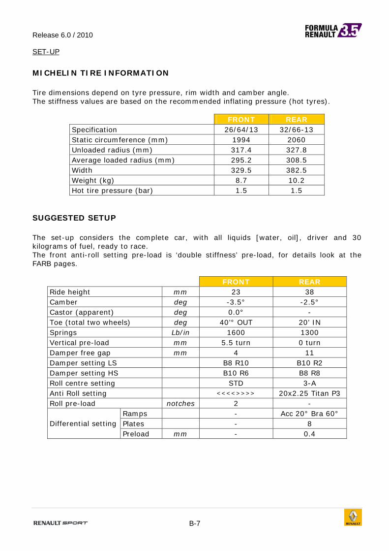
MICHELIN TIRE INFORMATION Tire dimensions depend on tyre pressure, rim width and camber angle. The stiffness values are based on the recommended inflating pressure (hot tyres).
FRONT REAR Specification 26/64/13 32/66-13 Static circumference (mm) 1994 2060 Unloaded radius (mm) 317.4 327.8 Average loaded radius (mm) 295.2 308.5 Width 329.5 382.5 Weight (kg) 8.7 10.2 Hot tire pressure (bar) 1.5 1.5
SUGGESTED SETUP The set-up considers the complete car, with all liquids [water, oil], driver and 30 kilograms of fuel, ready to race. The front anti-roll setting pre-load is ‘double stiffness’ pre-load, for details look at the FARB pages.
FRONT REAR Ride height mm 23 38 Camber deg -3.5° -2.5° Castor (apparent) deg 0.0° - Toe (total two wheels) deg 40’° OUT 20’ IN Springs Lb/in 1600 1300 Vertical pre-load mm 5.5 turn 0 turn Damper free gap mm 4 11 Damper setting LS B8 R10 B10 R2 Damper setting HS B10 R6 B8 R8 Roll centre setting STD 3-A Anti Roll setting <<<<>>>> 20x2.25 Titan P3 Roll pre-load notches 2 -
Ramps - Acc 20° Bra 60° Plates - 8 Differential setting Preload mm - 0.4

Release 6.0 / 2010
B-8
SETUP ADJUSTMENT
POSITIVE CHANGE IN: MEANS: Ride Height car moves up
Toe toe-out Camber upper part of rim outward Castor lower part of rim points ahead
FRONT REAR
PUSHROD ADJUSTER Ride Height change 6.00mm 7.56mm +1 barrel
TURN Camber change (deg) 0.1° 0.16°
Thread size M20x2R+7/16UNF-20L=3.27mm
M20x2R+1/2UNF-20L=3.27mm
TOE ADJUSTER (PER WHEEL) toe change (deg) 0.6° (per turn) 0.31° (per 1mm shim) thread step 1/4UNF-24
CAMBER SHIM
+1mm toe change (deg)
0.28° 0°
0.24° 0°
CASTOR ADJUSTER Castor change (deg) 0.34° 0.42° Thread step & size 1.06mm-1/4UNF-24 1.27mm-1/2UNF-20 Ride height change +0.20 mm +0.42 mm Camber change (deg) +0.19° +0.14° Toe change (deg) 0° 0.05°
+1TURN
SPRING PLATFORM
thread step (mm) 1.5 1.5 +1TURN height change (mm) 1.31 1.72
RATIOS WHEEL/SPRING RATIO (vertical) 0.874 1.15 WHEEL/BELLEVILLE RATIO (lateral) 1.704 ---- WHEEL/DROP LINK RATIO (roll) -- 1.61
ROLL CENTRE HEIGHT [from ground]
7.4 mm [down] STD: 32mm [up]
Spacers to adjust camber and rear toe are available in the following thickness.
FRONT: 1.0, 1.5 and 2.0 mm REAR: 0.5, 0.8, 1.0, 1.2, 1.5 and 2.0mm.
Combine these spacers to make fine adjustments. At the rear, you can adjust toe with differential spacers. At the front, because of the “mono” geometry, when the axle moves vertically by 1mm, the vertical spring is compressed by 1/0.87 mm. When the difference in wheel vertical movement, from side to side, is 2 mm, the Belleville stack is compressed by 1/1.704 mm.

Release 6.0 / 2010
B-9
FRONT SUSPENSION
SETTING THE VERTICAL SPRING PRE-LOAD
Mount the spring with the spring platform C just in contact with the spring. Mount the damper-spring assembly on the car and put the car with the driver
seated on the set-up floor. Bounce the car a few times to settle it down. Be sure that the droop-stop A is not in contact with the plate B. Set the desired ride height with the pushrod adjusters. Turn the droop-stop A in contact with plate B and tighten with its counter-nut. Turn spring platform C by the amount of turns to get the desired pre-load force

Release 6.0 / 2010
B-10
FRONT ANTI ROLL DEVICE AND ROLL PRELOAD There are three different ways of setting the front anti-roll Belleville washers. The platform thread step is 1.5 mm. There are 15 notches per turn, hence 0.1 mm preload per notch. [1] Select a stack configuration and turn the platforms (both sides) until just in contact with the stack. In this configuration there is no pre-load and the roll stiffness is the nominal stack stiffness. For example: the configuration <<>><< gives 761kg/mm stack stiffness. [2] By turning both platforms (use notches as a reference) you preload the system. The roll stiffness below the pre-load threshold is twice the nominal stack stiffness. The roll stiffness above the pre-load threshold is the nominal stack stiffness For example:” >><<>> + 5 notches “ has 0.5mm of roll preload and, up to 0.5 mm of side rocker movement, the stack stiffness is 761x2=1522kg/mm. [3] By turning both platforms (use notches as reference) and by locking the two extra locknuts the system is infinitely stiff, this means the rocker will not move as long as the force is lower than the pre-load. Once the side force overcomes the pre-load, the stiffness is the nominal stack stiffness. Both pre-load settings (2 and 3) generally help for sharper turn-in. No pre-load settings (1) can make the tyres last longer and make the car easier to drive. Above the pre-load, the stiffness gets back to the nominal stack stiffness. The driver may prefer not to overcome the pre-load in certain conditions (turn-in…) and to overcome the pre-load in some other conditions (mid corner, curbs…). Set accurately the transition point of ‘pre-load / no pre-load’ since the consequently stiffness variation is sudden and reflects immediately on the balance You can combine different stacks in series to achieve a progressive load / displacement characteristic. Pay attention to the following:
Total length of the combined stack should never be more than 28mm. The clearance between the platform and the rocker (B) should not be more than
6.5mm when the platform just touches the Belleville stack, with no pre-load. For any Belleville stack, in running conditions, the total of the rocker lateral
displacement plus the chosen pre-load must never reach the "Maximum Deflection" (see Table below), to avoid the side of the rocker to “bottom-out” suddenly.
Belleville thickness is 2.0 mm

Release 6.0 / 2010
B-11
BELLEVILLE STACK CONFIGURATIONS
Stack configuration
Stack stiffness [kg/mm]
Stack stiffness (preload) [kg/mm]
Stack length [mm]
Max deflection
[mm]
Max notches
<<<<>>>> 2504 5008 17.50 1.12 8 <<<>>> 1796 3592 13.50 1.12 8
<<<>>><<< 1197 2394 20.25 1.69 12 <<>><< 761 1522 14.25 1.69 12
<<>><<>> 571 1142 19.00 2.25 17 <<>><<>><< 457 914 23.75 2.81 22
<>< 362 724 8.25 1.69 14 <><> 272 544 11.00 2.25 17
<><>< 218 436 13.75 2.81 22 <><><> 181 362 16.50 3.37 26
<><><>< 155 310 19.25 3.93
Do not exceed
maximum notches with
preloaded configurations
28
FRONT ANTI-ROLL BAR
MRarb [-/-] 1,704
Track [m] 1,630
Stack configuration Stack Stiffness Stack Stiffness AntiSymmetric
Model
Stiffness @ Ground
Stiffness @ Ground
[kg/mm] [kg/mm] [kg/mm] [kgm/deg]
<<<<>>>> 2504 1252 431 10008
<<<>>> 1796 898 309 7177
<<<>>><<< 1197 599 206 4786
<<>><< 761 381 131 3041
<<>><<>> 571 286 98 2272
<<>><<>><< 457 229 79 1820
<>< 362 181 62 1443
<><> 272 136 47 1087
<><>< 218 109 38 873
<><><> 181 91 31 726
<><><>< 155 78 27 615

Release 6.0 / 2010
B-12
SETTING THE FRONT ROLL PRELOAD
DOUBLE STIFFNESS PRE-LOAD
Select and mount the stack and turn the platforms to contact the Belleville stack Turn the platforms until distance A is the same on both sides Check distance B to be less than 6.5mm, if it is more, replace the adjustment
spacer Mark this platform position as the “zero pre-load” notch Turn both left and right platforms by the same amount of notches to set the desired
pre-load. (1 notch = 0.1mm) The platform has 15 notches per turn
INFINITE STIFFNESS PRE-LOAD Set the pre-load as described for the double stiffness procedure described above Mount nut D in contact with the platform Tighten lock nut E against nut D, (1 notch = 0.1mm)

Release 6.0 / 2010
B-13
CASTOR
FRONT When the car is flat ( front and rear ride height are identical ) and the front upright inclination is 0.00° [APPARENT CASTOR ] the effective castor angle is 7.60° [ BUILT-IN CASTOR ]. With different front to rear ride heights, castor angle changes because of the pitch angle of the car. For instance, with 20 mm front and 35mm rear ride heights, measured at wheel axis, (wheelbase is 3125 mm) the pitch angle is 0.27° and castor angles (both apparent and total) are reduced. Pitch angle : [(35-20)/3125] 57.296 = 0,27° Total Castor angle : 7,60° - 0,27° = 7,33° Apparent Castor angle : 0,00° - 0,27° = -0,27°

Release 6.0 / 2010
B-14
FRONT SUSPENSION PICK-UP POINTS
REFERENCE POINT: X0: FRONT WHEEL AXIS Y0: LONGITUDINAL AXIS Z0: BOTTOM OF THE CHASSIS (NOT THE WOODEN SKID)
Front suspension coordinates X Y Z
1 267,0 18,0 147,1 2 -370,0 15,0 161,5 3 112,0 155,0 350,0 4 -296,5 192,5 349,8 5 170,0 170,0 353,5 6 -37,7 691,0 368,0 7 -11,1 724,6 167,7 8 57,3 720,5 369,5 9 0,0 815,0 -27,0
10 0,0 798,7 283,4 11 -10,3 676,5 195,4 12 0,0 70,0 542,5 13 75,0 60,0 539,0 14 155,0 0,0 562,0 15 275,0 0,0 249,1 16 75,0 -60,0 539,0

Release 6.0 / 2010
B-15
STEERING WHEEL:
For safety reason Dallara allows a minimum distance between the steering wheel assembly and the chassis (as in the following picture). Please check accurately. For distances close to 59 mm, the optional steering column support for taller drivers must be used (it is fixed on the front face of the bulkhead).
STEERING ASSEMBLY
Pinion primitive diameter [ mm ] 13.7 Static steering ratio 14.6 steering wheel/wheel

Release 6.0 / 2010
B-16
STEERING WHEEL HEIGHT To manage the steering wheel height two steps must be followed:
A. Use the support for tall drivers B. Add spacer between the second column support and the tub
The support for tall drivers (77 11 165 330) will raise the steering wheel of 5 mm approximately. To further raise the steering wheel, spacers can be added between the support and the tub. Make sure that the screws (M6 8.8) are long enough to maintain the support. You must use Loctite on the screws. There are two types of spacers:
8 mm 1 mm
The maximum height of the spacer stack is 14 mm
Use support for tall drivers
Add the spacers here to raise the steering wheel further

Release 6.0 / 2010
B-17
Procedure:
1. Un-tighten the nuts that keep the steering box in place
2. Insert spacers (up to 14 mm) between the monocoque and the intermediate support
3. By doing this, you will change the inclination of the steering box; it is allowed to
grind the Magnesium bulkhead in case the steering box touches in the area shown below (picture A); it is allowed as well to remove material from the leg padding in case the steering column touches in the area shown below (picture B)
Picture A Picture B
4. Once you get the position you want for the steering wheel, be sure that the steering
column can turn freely.

Release 6.0 / 2010
B-18
REAR SUSPENSION
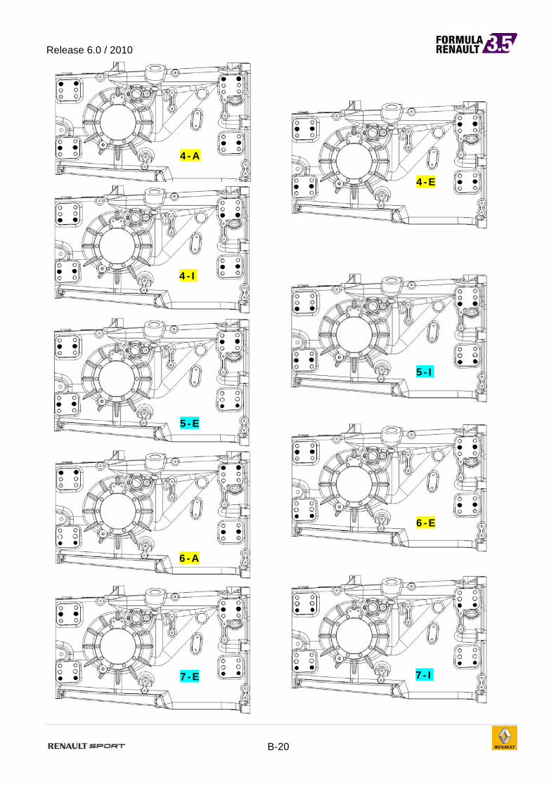
ROLL CENTER AND ANTISQUAT OPTIONS Roll center height is measured from the ground with the car at design ride height (35 mm).
DO NOT USE COMBINATIONS NOT LISTED BELOW !!!
OPTION Roll centre height
(Variation [mm] from STD)
Camber change for 10mm wheel
travel
Antisquat %
Antilift %
1-A +22.5 -0.20° 27,0 12,1 1-E +49.5 -0.30° 27,0 12,1
1-I +74.0
Shorten 1turn to adjust Bump Steer
-0.39° 27,0 12,1
2-A +5.0
Lengthen 2turns to adjust Bump Steer
-0.17° 11.1 -18.3
2-E +32.0
Lengthen 2.5turns to adjust Bump Steer
-0.27° 11.1 -18.3
2-I +58.0
Lengthen 3turns to adjust Bump Steer
-0.37° 11.1 -18.3
3-A -10.0
Shorten 1.5turns to adjust Bump Steer
-0.15° 42.8 42.5
3-E +17.0
Shorten 2.5turns to adjust Bump Steer
-0.25° 42.4 42.5
4-A -28.5 -0.12° 27.0 12.1 4-E
(STD) / -0.22° 27.0 12.1
4-I +26.5
Shorten 1turn to adjust Bump Steer
-0.32° 27.0 12.1
5-E -24
Lengthen 3 turns to adjust Bump Steer
-0.19° 11.6 -18.6
5-I +3.3
Lengthen 3 turns to adjust Bump Steer
-0.29° 11.6 -18.6
6-A -55
Shorten 3turns to adjust Bump Steer
-0.06° 42.6 41.8
6-E -27
Shorten 2.5 turns to adjust Bump Steer
-0.16° 42.6 41.9
7-E -51 -0.13° 27.0 12.1
7-I -29.3
Lengthen by 3 turns to adjust bump steer
-0.24° 27.3 12.3
Rear roll centre height in STD configuration is 32 mm from ground (with a static rear ride height of 35 mm). OPTIONS IN BLUE: The modification of the floor extension is compulsory (see page B21)

Release 6.0 / 2010
B-19
1-A
1-I
1-E
2-A
2-E 2-I
3-E 3-A
Release 6.0 / 2010
B-20
4-A
4-I
5-E
5-I
6-A
6-E
7-E 7-I
4-E

Release 6.0 / 2010
B-21
FLOOR EXTENSION MODIFICATION To comply with the lowest position of the lower wishbone used in options 5E, 5I, 7E, 7I, it is compulsory to perform the following modification to the floor extension.
The modification consists in cutting off a 15 mm stripe from the existing cut in the part. THIS MODIFICATION IS NOT COMPULSORY WHEN NOT USING THE MENTIONED POSITIONS When the rear lower wishbone is mounted on the gearbox using the upper position of the front mounting (configuration 1A, 1E, 1I, 3A and 3E), the forward leg of the wishbone is touching on the diffuser. In order to avoid any interference problem it is allowed to grind the underwing in the area shown in the picture. Furthermore, check that the brake line can’t be damage because of the contact with the diffuser.

Release 6.0 / 2010
B-22
REAR ANTIROLL BAR STIFFNESS There are four different T shaped anti roll bars: 20x2.25 mm 25 x 1.5 mm. 30 x 1.5 mm 30 x 5 mm And two blades: one made of steel, one made of titanium. Important: The titanium blade can exclusively be used with the Ø20 X 2.25 bar. At Full soft (Position 1) the blade is vertical. At Full Stiff (Position 5) the blade is horizontal.
REAR ANTI-ROLL BAR
MRarb [-/-] 1,614
Track [m] 1,529
P1 P2 P3 P4 P5
Component
Stiffness Component
Stiffness Component
Stiffness Component
Stiffness Component
Stiffness
[kg/mm] [kg/mm] [kg/mm] [kg/mm] [kg/mm]
Ø 20 x 2.25 Ti Blade
13 15 18 22 24
Ø 20 x 2.25 20 21 24 28 29 Ø 25 x 1.5 25 27 33 39 40 Ø 30 x 1.5 29 32 40 49 55
Ø 30 x 5 38 43 59 80 93
P1 P2 P3 P4 P5
Stiffness
@ Ground Stiffness
@ Ground Stiffness
@ Ground Stiffness
@ Ground Stiffness
@ Ground
[kg/mm] [kg/mm] [kg/mm] [kg/mm] [kg/mm]
Ø 20 x 2.25 Ti Blade
10 11 14 17 18
Ø 20 x 2.25 15 16 18 21 22
Ø 25 x 1.5 19 21 25 30 31
Ø 30 x 1.5 22 24 31 38 42
Ø 30 x 5 29 33 45 61 72
P1 P2 P3 P4 P5
Stiffness
@ Ground Stiffness
@ Ground Stiffness
@ Ground Stiffness
@ Ground Stiffness
@ Ground
[kgm/deg] [kgm/deg] [kgm/deg] [kgm/deg] [kgm/deg]
Ø 20 x 2.25 Ti Blade
206 229 280 341 372
Ø 20 x 2.25 308 328 374 431 457
Ø 25 x 1.5 393 429 509 608 632
Ø 30 x 1.5 454 496 626 766 861
Ø 30 x 5 598 678 921 1251 1461

Release 6.0 / 2010
B-23
Rear anti-roll stiffness ranges:
Rear ARB Stiffness - WSbR
0
200
400
600
800
1000
1200
1400
1600
Ø 20 x 2.25 Ti Blade Ø 20 x 2.25 Ø 25 x 1.5 Ø 30 x 1.5 Ø 30 x 5
Gro
un
d S
tiff
nes
s [k
gm
/deg
]

Release 6.0 / 2010
B-24
REAR SUSPENSION PICK-UP POINTS REFERENCE POINT : X0: REAR WHEEL AXIS Y0: LONGITUDINAL AXIS Z0: BOTTOM OF THE CHASSIS (NOT THE WOODEN SKID)
Rear suspension coordinates (4E –STD)
X Y Z 1 355.405 128.508 148.786
2 -157.179 118.497 133.570
3 355.531 157.023 331.576
4 -155.232 134.490 316.402
5 -155.232 134.490 316.402
6 75.829 586.991 379.000
7 28.593 664.923 158.300
8 -96.334 587.332 373.500
9 0.000 764.500 -42.000
10 0.000 753.262 279.804
11 33.685 608.773 184.091
12 66.066 151.997 395.943
13 117.500 132.874 404.258
14 74.381 30.864 448.613
15 368.000 85.000 425.000
16 117.500 92.998 312.552

Release 6.0 / 2010
B-25
SET-UP
RIDE HEIGHT CHECK AND REFERENCES
Front and rear ride heights are fundamental for setting and changing the aerodynamic performance of the car. It might be difficult to measure them directly, so we provide alternative references. The example shows the design configuration with front ride 20mm and rear ride height 35mm (at the wheel axis). Pitch angle in the design configuration is 0,275°. (3125 wheelbase) Measuring front ride height: [ 1 ] A flat surface (skid) about 286 mm behind the front wheel axis. You can calculate
the ride height at the wheel as follows: measured 22 - tan (pitch angle) · 286 = 20mm
Measuring rear ride height: [ 1 ] Two machined areas, at 382 mm from car bottom, on the gearbox aligned with the
wheel axis. Their distance from the ground is 417 – 382 = 35mm.
[ 2 ] Under the flat bottom, 314mm ahead of the rear wheel axis, you can easily measure the ground clearance and calculate the ride height at the rear axis as follows:
measured 34mm + tan ( pitch angle ) · 314 = 35 mm For a more general procedure
Define your desired ride heights, front and rear ( F & R ) [mm] Calculate the pitch angle ( R – F ) / 3125 · 57.29 Calculate which value you should measure in the reference you choose
FRONT [ mm ] REAR [ mm ] NOTES
A 20 35 DESIGN DIMENSIONS
B 22 34 UNDERTRAY DIMENSIONS

Release 6.0 / 2010
B-26
DRAWINGS

Release 6.0 / 2010
B-27
The drawing underneath represents the car with no tyre deformation.

Release 6.0 / 2010
B-28

Release 6.0 / 2010
B-29
NOSE FITTING
The nose fitting pins can be pre-adjusted by mounting them on the nose respecting the dimension illustrated below; which is 43,4mm from the top of the head of the pin to the nose counterbore hole on the nose in contact with the steel bush of the tub. After that, a fine tuning is required, in order to guarantee a good lock on each cam; by using the Allen key hole on the head of the pin.

Release 6.0 / 2010
B-30
AERODYNAMICS
DEFINITIONS Aero values are given @ the following ambient conditions;
Temperature = 15°C Pressure = 1013 mb Humidity = 0% (dry air)
Aeroloads are function of air temperature, pressure and humidity because they affect the air density. Typically, Higher Air Temperature by 5.5 °C (10° F) reduces downforce and drag by 3.0 % Higher Air Pressure by 1” Hg increases downforce and drag by 3.0% Higher Air Relative Humidity by 50% increases downforce and drag by 0.5%
Drag number includes front and rear wheels contribution Front Downforce is meant at the front axle Rear Downforce is meant at the rear axle Efficiency is Total Downforce / Drag Balance is the Downforce split percentage on front (=100*Lf /Lt).
AERODYNAMICS FEATURES OF THE CAR The 2008 Formula Renault 3.5 car was deeply inspired by the style of the most recent Renault F1 cars: the R27 was taken as example in the design process. As a result, more aerodynamic devices were present in this new Formula Renault 3.5: more profiles on the front wing assembly, extra wings on the body and various aerodynamic devices on the side pods, all of them giving their contribution to the generation of downforce and drag. As a consequence of the changes on aerodynamics that F1 cars will have since in 2009, the Formula Renault 3.5 has been updated in order to follow F1’s moves. In the following pages it is possible to find all the details concerning the aero devices installed in the car, together with the basic data needed for the definition of a complete aero set-up.

Release 6.0 / 2010
B-31
FRONT WING ASSEMBLY
Mainplane Design mainplane HEIGHT (from reference plane) 61 mm Design mainplane INCIDENCE (relative to reference plane) 1.1°

Release 6.0 / 2010
B-32
Flap Flap angle is measured:
- at the plane where the chord is maximum - on upper surface (drawing a line above the flap) - from the reference plane (with zero rake)
The flap angle can be between 3 and 32 degrees. Nominal SLOT GAP is 13.0 mm. Nominal OVERLAP between the flap and the main plane is : 22.0 mm.
Gurney (Nolder) 10 mm height front flap Gurneys are increasing the front downforce of 3% approximately. To balance front flap Gurney, the front flap incidence must be reduced of 7 holes. Each Gurney must be fitted with M3 bolts (We recommend the use of domed head screws with the nut on the top for aerodynamic efficiency). The flaps must be drilled accordingly to the holes present on the Gurneys. Important information:
The use of the front flap Gurneys is not compulsory Flaps can remain without holes if the Gurneys are not used New flaps will be sold without holes

Release 6.0 / 2010
B-33
Endplate The endplate is divided into two parts: the lower part is more subject to wear and damages (e.g. on kerbs) and it’s easier to replace if separated from the main upper part. Furthermore, this lower part is shaped in a way that the possibility of damage to other cars in case of contact is minimum.
The holes on the endplate allow a flap angle range between 3 and 32 degrees (1 deg step).
1 2 3 4 5 A 3 9 15 21 27 B 4 10 16 22 28 C 5 11 17 23 29 D 6 12 18 24 30 E 7 13 19 25 31 F 8 14 20 26 32

Release 6.0 / 2010
B-34
MAIN BODY AND UNDERWING

Release 6.0 / 2010
B-35
Underwing and skirts The underwing with its diffuser and the skirts placed on each side play a major role in the generation of downforce. Be aware that the skirts have been designed to work with their lower point 5 mm above the reference plane: set the skirts’ heights carefully in order to get the best performance out of them. Remember also that skirts wear down quite easily: there is no need to destroy them during warm up laps, when the tyres are not ready. A worn skirt is producing less downforce because the “sealing” effect between the car and the ground is reduced; furthermore, if the skirts wear down unevenly (e.g.: the rearmost part of the skirt is destroyed and the foremost is almost untouched, or vice-versa), the aerodynamic balance can move significantly to the front / rear of the car.

Release 6.0 / 2010
B-36
REAR WING ASSEMBLY

Release 6.0 / 2010
B-37
Mainplane Design mainplane HEIGHT (from reference plane) 337 mm Design mainplane INCIDENCE (relative to reference plane) 10° Sideplate Design mainplane HEIGHT (from reference plane) 337 mm
Biplane The rear biplane can be installed in the car in three different configurations, depending on the type of track and on the grip conditions:
- high downforce (HFD) - medium downforce (MDF) - low downforce (LDF)

Release 6.0 / 2010
B-38
High downforce (HDF): The “high downforce” biplane assembly is made of:
- the STD mainplane - the HDF flap - the two STD steel sideplate (in order to allow adjustments)
Nominal OVERLAP between the flap and the main plane is : 36.0 mm Angle between mainplane and flap is 49 degrees. Biplane angle is measured:
- on the upper surface (drawing a line above the flap and tangent to the mainplane) - from the reference plane (with zero rake)

Release 6.0 / 2010
B-39
Medium downforce (MDF): The “medium downforce” biplane assembly is made of:
- the STD mainplane - the MDF flap (it is the STD flap used in the T05 biplane) - the two STD steel sideplate (in order to allow adjustments)
Nominal OVERLAP between the flap and the main plane is : 31.0 mm Angle between mainplane and flap is 38 degrees.

Release 6.0 / 2010
B-40
Low downforce (LDF): The “low downforce” biplane assembly is made of:
- the STD mainplane - the two STD steel sideplate (in order to allow adjustments)

Release 6.0 / 2010
B-41
Biplane adjustment The holes machined on the steel sideplates allow biplane angles between 11 and 28 degrees.
1 2 3 A 11 17 23 B 12 18 24 C 13 19 25 D 14 20 26 E 15 21 27 F 16 22 28

Release 6.0 / 2010
B-42
LOW DOWNFORCE AERODYNAMIC CONFIGURATION (LAC) Here are the restrictions that must be observed when “LAC” is required:
Skirts cannot be used MDF rear profile must be used on the first line of holes exclusively
Other information: The skirt supports (77 11 165 315 & 316) must be removed when the skirts are not
used. No restriction is made on the front wing A specific adhesive covering lines 2 & 3 must be applied when LAC is required to
ensure a quick control The specific adhesive will be distributed by Renault Sport during preliminary
scrutineering LDF cannot be used when LAC is required
Release 6.0 / 2010
B-43
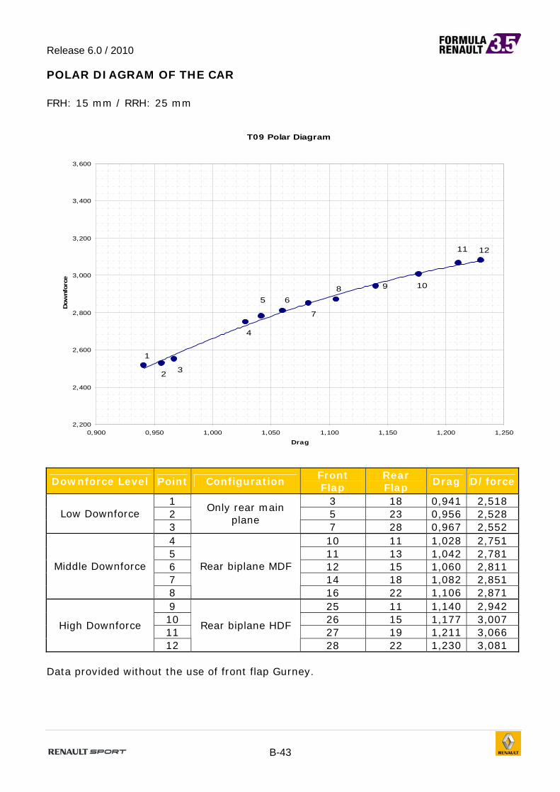
POLAR DIAGRAM OF THE CAR FRH: 15 mm / RRH: 25 mm
T09 Polar Diagram
1211
1098
7
65
4
1
2 3
2,200
2,400
2,600
2,800
3,000
3,200
3,400
3,600
0,900 0,950 1,000 1,050 1,100 1,150 1,200 1,250
Drag
Dow
nforc
e
Downforce Level Point Configuration Front Flap
Rear Flap
Drag D/force
1 3 18 0,941 2,518 2 5 23 0,956 2,528 Low Downforce 3
Only rear main plane
7 28 0,967 2,552 4 10 11 1,028 2,751 5 11 13 1,042 2,781 6 12 15 1,060 2,811 7 14 18 1,082 2,851
Middle Downforce
8
Rear biplane MDF
16 22 1,106 2,871 9 25 11 1,140 2,942 10 26 15 1,177 3,007 11 27 19 1,211 3,066
High Downforce
12
Rear biplane HDF
28 22 1,230 3,081 Data provided without the use of front flap Gurney.

Release 6.0 / 2010
B-44
AERO MAPS Low downforce CxT CzT
FRH/RRH 5 10 15 20 25 30 35 40 45 FRH/RRH 5 10 15 20 25 30 35 40 45
5 0,952 0,958 0,961 0,962 0,965 0,966 0,970 5 2,823 2,809 2,792 2,784 2,788 2,800 2,806
10 0,955 0,957 0,958 0,958 0,960 0,965 0,966 0,970 10 2,677 2,645 2,646 2,646 2,651 2,689 2,660 2,640
15 0,948 0,948 0,949 0,954 0,956 0,960 0,962 0,964 0,968 15 2,522 2,491 2,489 2,513 2,528 2,541 2,507 2,477 2,448
20 0,945 0,949 0,952 0,956 0,957 0,959 0,961 0,961 20 2,373 2,377 2,400 2,428 2,414 2,376 2,343 2,298
25 0,946 0,950 0,951 0,953 0,955 0,956 0,958 25 2,289 2,316 2,321 2,303 2,264 2,225 2,187
30 0,948 0,949 0,950 0,951 0,952 0,953 30 2,231 2,229 2,194 2,164 2,121 2,087
35 0,947 0,948 0,949 0,950 0,951 35 2,138 2,109 2,061 2,029 2,011
CzF CzR
FRH/RRH 5 10 15 20 25 30 35 40 45 FRH/RRH 5 10 15 20 25 30 35 40 45
5 1,203 1,202 1,199 1,203 1,210 1,218 1,222 5 1,620 1,607 1,594 1,581 1,579 1,581 1,584
10 1,104 1,098 1,107 1,112 1,118 1,138 1,130 1,128 10 1,573 1,547 1,539 1,535 1,533 1,551 1,530 1,512
15 1,007 1,005 1,012 1,026 1,036 1,047 1,037 1,031 1,028 15 1,515 1,487 1,477 1,486 1,492 1,495 1,470 1,446 1,421
20 0,929 0,936 0,951 0,968 0,965 0,956 0,949 0,937 20 1,443 1,441 1,449 1,460 1,449 1,421 1,394 1,360
25 0,877 0,892 0,898 0,894 0,886 0,877 0,869 25 1,411 1,424 1,424 1,408 1,379 1,348 1,319
30 0,832 0,836 0,831 0,825 0,814 0,807 30 1,398 1,393 1,363 1,339 1,307 1,281
35 0,782 0,778 0,765 0,759 0,759 35 1,356 1,332 1,296 1,270 1,252
Eff R.A.%
FRH/RRH 5 10 15 20 25 30 35 40 45 FRH/RRH 5 10 15 20 25 30 35 40 45
5 2,966 2,933 2,904 2,895 2,891 2,898 2,891 5 42,6% 42,8% 42,9% 43,2% 43,4% 43,5% 43,6%
10 2,804 2,765 2,762 2,763 2,761 2,788 2,754 2,722 10 41,2% 41,5% 41,8% 42,0% 42,2% 42,3% 42,5% 42,7%
15 2,660 2,627 2,621 2,633 2,645 2,648 2,605 2,568 2,530 15 39,9% 40,3% 40,7% 40,8% 41,0% 41,2% 41,3% 41,6% 42,0%
20 2,510 2,507 2,522 2,539 2,523 2,479 2,439 2,392 20 39,2% 39,4% 39,6% 39,9% 40,0% 40,2% 40,5% 40,8%
25 2,419 2,438 2,440 2,416 2,371 2,328 2,283 25 38,3% 38,5% 38,7% 38,8% 39,1% 39,4% 39,7%
30 2,354 2,349 2,308 2,275 2,229 2,190 30 37,3% 37,5% 37,9% 38,1% 38,4% 38,6%
35 2,259 2,224 2,171 2,135 2,113 35 36,6% 36,9% 37,1% 37,4% 37,7%
Configuration: Front : Front flap @ 5° Rear: LDF @ 23°
Data provided without the use of front flap Gurney.

Release 6.0 / 2010
B-45
Medium downforce CxT CzT
FRH/RRH 5 10 15 20 25 30 35 40 45 FRH/RRH 5 10 15 20 25 30 35 40 45
5 1,050 1,053 1,060 1,064 1,068 1,073 1,080 5 3,167 3,116 3,085 3,077 3,090 3,105 3,138
10 1,048 1,050 1,054 1,058 1,062 1,069 1,077 1,082 10 2,965 2,942 2,901 2,897 2,926 2,957 2,964 2,953
15 1,044 1,046 1,050 1,054 1,060 1,066 1,076 1,076 1,079 15 2,805 2,774 2,777 2,779 2,811 2,840 2,838 2,805 2,779
20 1,046 1,049 1,052 1,059 1,063 1,071 1,074 1,079 20 2,672 2,658 2,693 2,733 2,726 2,711 2,687 2,655
25 1,048 1,052 1,058 1,062 1,068 1,071 1,073 25 2,577 2,613 2,628 2,625 2,598 2,570 2,541
30 1,050 1,056 1,060 1,067 1,067 1,072 30 2,520 2,530 2,523 2,498 2,457 2,444
35 1,056 1,058 1,066 1,068 1,071 35 2,454 2,440 2,414 2,384 2,350
CzF CzR
FRH/RRH 5 10 15 20 25 30 35 40 45 FRH/RRH 5 10 15 20 25 30 35 40 45
5 1,356 1,341 1,335 1,337 1,346 1,354 1,369 5 1,811 1,774 1,750 1,740 1,744 1,751 1,768
10 1,227 1,229 1,219 1,219 1,237 1,251 1,256 1,260 10 1,738 1,713 1,683 1,678 1,689 1,706 1,708 1,693
15 1,128 1,123 1,132 1,136 1,151 1,169 1,173 1,166 1,163 15 1,678 1,650 1,646 1,643 1,660 1,671 1,665 1,639 1,617
20 1,057 1,052 1,070 1,089 1,090 1,089 1,086 1,079 20 1,615 1,606 1,623 1,643 1,636 1,622 1,601 1,575
25 0,995 1,014 1,021 1,024 1,016 1,011 1,006 25 1,582 1,600 1,607 1,601 1,582 1,558 1,535
30 0,955 0,960 0,959 0,954 0,944 0,944 30 1,566 1,570 1,564 1,544 1,513 1,500
35 0,909 0,906 0,901 0,895 0,887 35 1,545 1,534 1,513 1,489 1,463
Eff R.A.%
FRH/RRH 5 10 15 20 25 30 35 40 45 FRH/RRH 5 10 15 20 25 30 35 40 45
5 3,016 2,960 2,910 2,892 2,893 2,892 2,905 5 42,8% 43,1% 43,3% 43,4% 43,6% 43,6% 43,6%
10 2,828 2,802 2,754 2,739 2,754 2,766 2,752 2,730 10 41,4% 41,8% 42,0% 42,1% 42,3% 42,3% 42,4% 42,7%
15 2,686 2,650 2,645 2,637 2,651 2,664 2,638 2,607 2,575 15 40,2% 40,5% 40,7% 40,9% 41,0% 41,2% 41,3% 41,6% 41,8%
20 2,555 2,534 2,558 2,582 2,566 2,532 2,502 2,460 20 39,6% 39,6% 39,7% 39,9% 40,0% 40,2% 40,4% 40,7%
25 2,460 2,484 2,484 2,473 2,433 2,399 2,368 25 38,6% 38,8% 38,8% 39,0% 39,1% 39,4% 39,6%
30 2,399 2,396 2,380 2,342 2,303 2,281 30 37,9% 37,9% 38,0% 38,2% 38,4% 38,6%
35 2,325 2,305 2,265 2,232 2,195 35 37,1% 37,1% 37,3% 37,5% 37,7%
Configuration: Front : Front flap @ 12° Rear: MDF @ 15°
Data provided without the use of front flap Gurney.

Release 6.0 / 2010
B-46
High downforce CxT CzT
FRH/RRH 5 10 15 20 25 30 35 40 45 FRH/RRH 5 10 15 20 25 30 35 40 45
5 1,204 1,208 1,216 1,228 1,235 1,240 1,248 5 3,395 3,327 3,317 3,306 3,308 3,334 3,346
10 1,217 1,221 1,219 1,224 1,235 1,241 1,246 1,249 10 3,238 3,186 3,175 3,175 3,194 3,220 3,213 3,187
15 1,217 1,215 1,222 1,228 1,230 1,241 1,243 1,249 1,251 15 3,097 3,075 3,067 3,073 3,081 3,120 3,092 3,073 3,052
20 1,217 1,220 1,224 1,228 1,234 1,239 1,243 1,249 20 2,980 2,969 2,978 3,006 3,001 2,987 2,951 2,927
25 1,218 1,223 1,229 1,233 1,235 1,241 1,245 25 2,883 2,906 2,924 2,919 2,881 2,857 2,823
30 1,219 1,225 1,231 1,236 1,238 1,242 30 2,833 2,833 2,825 2,795 2,756 2,729
35 1,227 1,227 1,232 1,236 1,241 35 2,767 2,725 2,700 2,671 2,651
CzF CzR
FRH/RRH 5 10 15 20 25 30 35 40 45 FRH/RRH 5 10 15 20 25 30 35 40 45
5 1,445 1,421 1,423 1,420 1,421 1,435 1,441 5 1,950 1,905 1,894 1,886 1,887 1,899 1,906
10 1,340 1,331 1,326 1,328 1,340 1,351 1,352 1,346 10 1,898 1,854 1,848 1,847 1,855 1,869 1,861 1,842
15 1,254 1,251 1,249 1,257 1,262 1,278 1,272 1,267 1,267 15 1,843 1,824 1,818 1,816 1,819 1,843 1,821 1,805 1,786
20 1,186 1,183 1,190 1,205 1,206 1,204 1,195 1,187 20 1,794 1,786 1,787 1,801 1,794 1,784 1,756 1,740
25 1,129 1,138 1,147 1,148 1,140 1,132 1,124 25 1,754 1,768 1,776 1,772 1,742 1,725 1,699
30 1,092 1,089 1,090 1,082 1,071 1,065 30 1,741 1,744 1,735 1,713 1,685 1,664
35 1,042 1,033 1,026 1,018 1,015 35 1,725 1,692 1,674 1,653 1,636
Eff R.A.%
FRH/RRH 5 10 15 20 25 30 35 40 45 FRH/RRH 5 10 15 20 25 30 35 40 45
5 2,820 2,754 2,727 2,692 2,679 2,689 2,681 5 42,6% 42,7% 42,9% 42,9% 43,0% 43,0% 43,1%
10 2,661 2,609 2,605 2,593 2,587 2,594 2,579 2,551 10 41,4% 41,8% 41,8% 41,8% 41,9% 42,0% 42,1% 42,2%
15 2,545 2,529 2,511 2,503 2,505 2,514 2,488 2,461 2,440 15 40,5% 40,7% 40,7% 40,9% 41,0% 40,9% 41,1% 41,2% 41,5%
20 2,448 2,434 2,432 2,447 2,432 2,412 2,374 2,343 20 39,8% 39,9% 40,0% 40,1% 40,2% 40,3% 40,5% 40,6%
25 2,368 2,375 2,379 2,367 2,333 2,303 2,268 25 39,2% 39,2% 39,2% 39,3% 39,5% 39,6% 39,8%
30 2,325 2,313 2,295 2,261 2,226 2,197 30 38,5% 38,4% 38,6% 38,7% 38,9% 39,0%
35 2,255 2,221 2,192 2,161 2,136 35 37,7% 37,9% 38,0% 38,1% 38,3%
Configuration: Front : Front flap @ 28° Rear: HDF @ 22°
Data provided without the use of front flap Gurney.
COOLING INLET BLANKING
Description SCxT SCzF SCzR 0VVrad
(each side)
No blanking Ref Ref Ref Ref
50 mm horizontal 0.000 0.000 +0.005 -2.3%
100 mm horizontal +0.001 +0.004 +0.023 -5.8%

Release 6.0 / 2010
B-47
POLAR DIAGRAM OF THE MAIN ADJUSTABLE DEVICES FRH : 15 mm / RRH : 25 mm FRONT FLAP Data provided without the use of front flap Gurney.
Front wing flap angle CxT*S CzF*S CzR*S BalFr%
3 Ref Ref Ref 41,09 5 -0,002 0,012 -0,045 42,10 8 -0,004 0,052 -0,087 43,70
LDF
(rear @15°) 12 -0,001 0,095 -0,159 45,91 3 Ref Ref Ref 35,80 6 0,001 0,027 -0,061 37,15 13 0,004 0,104 -0,171 40,29 18 0,009 0,163 -0,239 42,50
MDF
(rear @11°) 22 0,013 0,191 -0,278 43,65 3 Ref Ref Ref 32,21 6 0,001 0,042 -0,028 33,56 13 0,002 0,168 -0,109 37,47 18 0,005 0,227 -0,177 39,68 23 0,008 0,266 -0,218 41,11
HDF
(rear @14°)
28 0,012 0,306 -0,261 42,58 REAR BIPLANE
Wing angle CxT*S CzF*S CzR*S BalFr% 18 Ref Ref Ref 43,0 21 0,008 0,001 0,030 42,5 25 0,020 0,003 0,055 42,1
LDF
(front @8°) 28 0,024 -0,003 0,077 41,6 11 Ref Ref Ref 42,0 15 0,0315 -0,0150 0,0654 40,4 18 0,0506 -0,0203 0,1174 39,8 20 0,0646 -0,0270 0,1511 39,2
MDF
(front @11°) 22 0,0749 -0,0302 0,1693 38,9 11 Ref Ref Ref 39,8 13 0,018 -0,004 0,033 39,4 18 0,061 -0,007 0,115 38,1 20 0,073 -0,010 0,132 37,8 22 0,090 -0,009 0,157 37,5
HDF
(front @16°)
25 0,095 -0,009 0,154 37,5

Release 6.0 / 2010
B-48
OIL SYSTEM
Keep the oil level at 40 mm above the inferior partition wall. Less oil may cause cavitation: air would get into the oil circuit, more oil may absorb
more power. Typically you would need 9 -10 litres to fill the oil tank (including oil lines).
OIL LEVEL AND CHARACTERISTICS
Name Capacities Characteristics Remarks Engine oil (mandatory) 10.0L ELF XT 3818 With radiators
Gearbox oil 3.5 L Elf HTX 755 or
Castrol SAF XJ SAE 75W140 With radiators
Fuel 110 L 98 Unleaded or Elf E85 Maximal capacity
Cooling Fluid 9.0 L Glaceol RX
Type D - With radiators
Brake Fluid 0.7 L ELF XT DOT5 DOT 5 Mini -
Hydraulic fluid 0.8 L ELF MATIC G3
or G3 SYN Dextron 3 High pressure system
Clutch Fluid 0.15 L ELF XT DOT5 DOT 5 Mini -
PLEASE NOTE THAT THE USE OF THE SPECIFIED ENGINE OIL IS MANDATORY

Release 6.0 / 2010
B-49
HYDRAULIC OIL SYSTEM
Keep the hydraulic oil level at the top of the plate (see image) to avoid any problems with the clutch and gear box release system.

Release 6.0 / 2010
B-50
ENGINE COMPARTMENT COOLING
4 areas must be cooled by bring a tube directly on the element:
- Fusebox - Alternator - Hydraulic block - Hydraulic pump
For all these areas, make sure that the extremity of the tube is in contact with the body of the element that needs cooling. Fusebox
Alternator

Release 6.0 / 2010
B-51
Hydraulic pump and hydraulic block

Release 6.0 / 2010
B-52
EXTRACTABLE SEAT
CARBON SHELL AND LEG STRAP POSITION Please keep in mind that, in case of an important crash, the driver should be extracted with no harm and no difficulties. On this purpose you should be sure that the following points are respected when you make your driver’s seat.
Make sure that the seat is correctly fitted in the carbon shell (A). Make sure that the holes for the leg straps (D) in the carbons shell (A) and in the
seat are in front of each others. Make sure that the leg straps (D) are exiting in front of the driver’s crotch. Make sure that, the driver doesn’t sit on the leg straps (D) when he is sitting in the
car. In order to be able to place the straps correctly, the following modification must be performed on all carbon shell:
A
D
B
C

Release 6.0 / 2010
B-53
Here are some illustrations of these points (sources: F.I.A.):
The hole made in the driver seat to pass the lower seat belts must be large enough. Some tape can be added on the lower belt in order to avoid any friction during the extraction.
The non respect of this rule will be considered as a non conformity

Release 6.0 / 2010
B-54
BLACK SOCKET POSITION The black plastic sockets must be maintained in position on the edge of the carbon shell in order to allow a quick fitting of the extraction tools. You can use one piece of black tape for this purpose. The tape should not prevent the belt from extension.
We would like to remind you that no other modification is allowed on the carbon shell (category A). Please modify the driver’s seat instead in case of problem.
SIDE BELTS It is recommended that the side belts of the carbon shell are attached together to avoid them being trapped between the shell and the chassis. Please use white paper tape easily tearable like shown in the picture underneath. Keep in mind that the socket must always be in the upper position.
Black Tape
Carbon shell
Socket
Belt

Release 6.0 / 2010
B-55
DRIVER SEAT DIMENSION The driver seat must not exceed the carbon shell length and width. CARBON SHELL MODIFICATION The extractible seat must be modified only if the lower seat-belt position is used on the tub. Remove the material according to the drawing underneath.

Release 6.0 / 2010
B-56
FUEL SYSTEM
Formula Renault 3.5 uses twin electrical-submerged fuel pumps as a precaution in case one pump fails. Fuel Tank capacity 110 L High pressure fuel pump flow 200 L/h (5bar)
ENGINE

Release 6.0 / 2010
B-57
EXTINGUISHER SYSTEM LAY-OUT
DETAILS The Formula Renault 3.5 estinguisher is filled with E85 compliant liquid. The Lifeline system is an electrically triggered Halon or foam spray fire extinguisher system. The system uses actuators to operate the valves located on the pressurised container, containing the extinguishing liquid. These are triggered remotely using a battery powered ‘power pack’. In order to guarantee reliability the actuators are of military specifications. The system/battery test electronics are integrated into the remote power pack. Connectors on the firing heads are also of military grade and use two contacts per lead to guarantee the best connections. Actuators are designed either to operate individually, or connected in series if two heads are used. All Lifeline Zero 2000 electrical extinguisher kits have a separate power pack to provide the current needed to operate the system. The power pack should be wired independently from the vehicle’s electrics as failure to do this may result in the actuation of the system due to electrical interference from the vehicle’s power source. Once the system has been wired a test check should be carried out to ensure that the system will fire properly. Before you start the check procedure, ensure that the bottle and the power pack are connected. On top of the power pack is a three position switch. This provides checking facilities for the battery and operation. If the switch is pulling against its spring towards the amber diode, the diode will light if there is sufficient current in the battery. IF THE DIODE DOES NOT LIGHT, OR IMMEDIATELY GOES OUT, IT SHOULD BE REPLACED. THE BATTERY SHOULD BE OF THE MANGANESE/ALKALINE TYPE ONLY.

Release 6.0 / 2010
B-58
With the switch in the centre (‘’system isolated’’) position, and the centre position only, the wiring of the circuit can be checked. With the extinguisher(s) connected, press one of the firing buttons and the green diode should light. If it does not there is a break in the circuit. If the diode lights before the button is pressed, there is a short in the circuit and the system is permanently ‘’live’’. If this occurs, DO NOT PUT THE SWITCH INTO THE ‘’SYSTEM ARMED’’ POSITION, OR YOU WILL DISCHARGE THE SYSTEM. If, for any reason, the green LED does not illuminate when the system is tested, check the wiring. If the problem persists consult Lifeline. To arm the system place the switch in to the “SYSTEM ARMED’’ position. The red LED will illuminate to indicate the system is armed. To prolong battery life and prevent accidental activation it is recommended that the power pack switch be in the ‘’SYSTEM ISOLATED’’ position and the plug disconnected.
TESTING The power pack electronics can test the continuity of the electrical wiring, and provide a high current pulse test on the battery, to ensure system integrity before use. The battery test electronics do not excessively drain the battery during this test. The tests are carried out using a three-way switch on the power pack. Since the system is only as good as the battery that powers it and the integrity of the wiring and its connections, the tests should be performed before each race. To check the battery, press and hold up the power pack switch. Every 2 seconds you’ll see a YELLOW light flash. If the light flashes very dimly the battery should be replaced. In doubt change the battery. To check the wiring continuity, ensure that the power pack switch is on “SYSTEM INACTIVE” to ensure that the extinguisher is not fired. Press the internal firing button and check that the RED light comes on. Press the external firing button and check that this also makes the RED light comes on.
PRECAUTIONS Ensure that the electric ‘command’ cables are not laying next to or in the same loom as the car battery power cables or ignition cables. Ideally, all cables should lie next to the chassis (earth). Ensure that all plugs exposed to water spray are protected with rubber boots. If tubing is to be removed, push the orange collet in. While holding in the collet, pull out the tube. Avoid running any cable over sharp edges without protection. Do not fix the cables next to or onto any surface likely to exceed 200°C. Do not turn the firing heads when the system is activated.

Release 6.0 / 2010
B-59
SBS 30 – DRY BATTERY
CHARGING PROCEDURE
Only use specific DRY BATTERY chargers!!!! • The charger must give a constant tension of 14.7V • The charger must be able to charge with a current of at least 40% of the nominal capacity of 26-27Ah, which is about 10A.The current will come down during charging.
• A complete charge can take up to 10 hours.
SAFETY NOTES • Never charge the battery when the battery is “HOT”. • Tighten the cable-nuts to no more than 4Nm. • Charge an empty battery immediately, do not leave it empty. • When the battery is stored do not let the tension come down under 12V but charge it again as soon as possible. • Store the batteries in an ambient temperature of about 25°C. Hotter conditions will reduce the life of the battery. • Make sure that all breather holes stay un-covered. • Fit the battery securely in its position, without fitting it too rigidly. Use some extra foam to reduce vibrations. SPARE BATTERY For security reasons, the “+” wire of the park battery loom must be plugged on the exit side of the master switch. In case of lateral crash when the master switch is off, this will prevent any current to run in the battery park loom. The thimble use on the master switch is Ø8 mm.

Release 6.0 / 2010
B-60
SWITCH PLATE
For driver comfort, it is allowed to remove material from both the switch plates according to the area shown in the drawing underneath.

Release 6.0 / 2010
B-61
SWG & CONVERSION TABLE
SHEET METAL THICKNESS
SWG 8 10 12 14 16 18 20 Metric [mm] 4.064 3.251 2.642 2.032 1.626 1.219 0.914
UNIT CONVERSION TABLE
1 millimetre=0.03937 in 1 foot=304.8 mm=12 in 1 centimetre=0.3937 in 1 yard=914.4 mm=3 ft 1 meter=39.37 in 1 mile=5280 ft=1.60934 km 1 kilometre=0.62137 miles
Volume
1 cubic inch (c.i.)=16.387 cubic centimetres
1 cubic centimetre=0.061 cubic inch
1 litre=1000 cc=61.0255 cubic inch
Pressure
1 psi=0.06894757bar 1 kg/cm2=1.019 bar 1 bar=105 Pa=0.1MPa 1 bar=14.503 psi
Weight
1 ounce (oz)=28.35 grams 1 Kg=1000 grams = 2.205 lb 1 pound (lb.)=16 ounces=453.592 grams
Speed
1 mph=1.609344 kilometres per hour 1 kilometre per hour=0.6213712 mph 1 IPS (in/s)=25.4 mm/s 1 mm/s=0.039 IPS
Specific weight
Water = 1.000 kg/l Mineral Oil = 0.903 Kg/l Gasoline = 0.740 Kg/l
Useful formulas
Engine displacement = 0.7854 × bore × bore × stroke × no. of cylinders British horsepower (BHP) = RPM × torque (lbs ft)/5250 Km/h = RPM × tire diameter (mm)/(gear ratio × 5308) Lap speed (km/h) = track length (Km) × 3600/lap time (s) Average speed (km/h) = track length (Km) ×3600 × no. of laps/total time (seconds)


![Chassis - U14R[1]](https://static.fdocuments.us/doc/165x107/55cf96d1550346d0338df988/chassis-u14r1.jpg)