CCTV Camera Systems for Harsh & Industrial … CCTV Camera Systems for Harsh & Industrial Environments
Upload
shavonne-harrisCategory
view
216download
1
1
CCTV SYSTEMS
PAN, TILT AND ZOOM CAMERAS
2
CCTV SYSTEMS
A PTZ camera is a pan, tilt, and zoom camera that is different from a fixed dome camera in that it can move up, down, left and right, and is able to zoom in and out providing a great deal of versatility.
Due to their versatility and flexibility, a PTZ camera requires a receiver (although some PTZ dome camera systems usually feature an integrated receiver) and keyboard to operate the pan, tilt, and zoom functions.
3
CCTV SYSTEMS
PTZ cameras are able to utilize alarm triggers to automatically move the camera where it is required to view.
With PTZ dome cameras the total zoom capacity is usually a combination of the optical zoom and the digital zoom.
This usually works by the use of electronics that uses the optical zoom for lens motion, and the digital zoom to zoom in and out of a specific object.
4
CCTV SYSTEMS
The security camera’s total zoom is then calculated by simply multiplying the optical zoom by the digital zoom to provide the zoom total.
Because of their unique dome shaped appearance they are able to provide a rotation of 360° allowing for them to view in any location, even straight down, by the use of an auto-flip function.
5
CCTV SYSTEMS
The auto-flip function enables the camera to automatically rotate when an object passes below it and ensures that the person or object is viewed upright on the monitor viewing screen.
This helps to keep constant monitoring of objects without having to be slowed by images that are unclear or not in the right position.
6
CCTV SYSTEMS
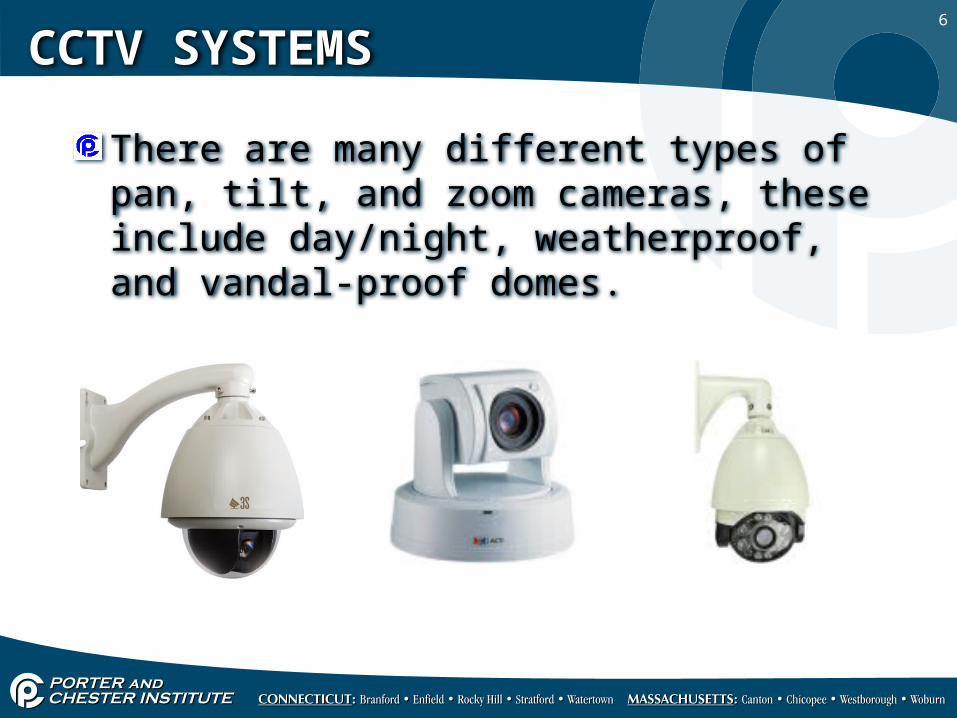
There are many different types of pan, tilt, and zoom cameras, these include day/night, weatherproof, and vandal-proof domes.
7
CCTV SYSTEMS
Vandal-proof dome camera systems are generally used in high risk locations where vandalism takes place against the camera itself.
These types of PTZ domes are usually able to withstand most types of vandalism such as rock throwing, and may be able to be linked to an alarm system when the dome is spray-painted or the viewing is obscured by an object.
8
CCTV SYSTEMS
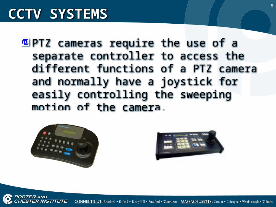
PTZ cameras require the use of a separate controller to access the different functions of a PTZ camera and normally have a joystick for easily controlling the sweeping motion of the camera.
9
CCTV SYSTEMS
Camera controllers can control multiple cameras in a CCTV system and provide other functions such as:
Adjusting for different lighting levelsAdjust the viewing angleAdjust the FOV (field of view)
10
CCTV SYSTEMS
PTZ controllers can provide preprogramming functions and timing functions of the PTZ camera essentially establishing presets.
A PTZ camera will need the typical video feed which is a coax cable with a BNC termination.
It will also need a control or communication link and a power lead.
11
CCTV SYSTEMS
There are several different interfaces used to hook up a PTZ camera to a controller:
RS232, RS423, RS422, RS485 and twisted pair (RJ-11).
The RS232, 422 and 423 are older serial bus standards that are typically used in computer interfaces.
12
CCTV SYSTEMS
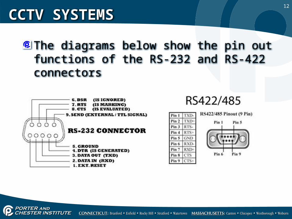
The diagrams below show the pin out functions of the RS-232 and RS-422 connectors
13
CCTV SYSTEMS
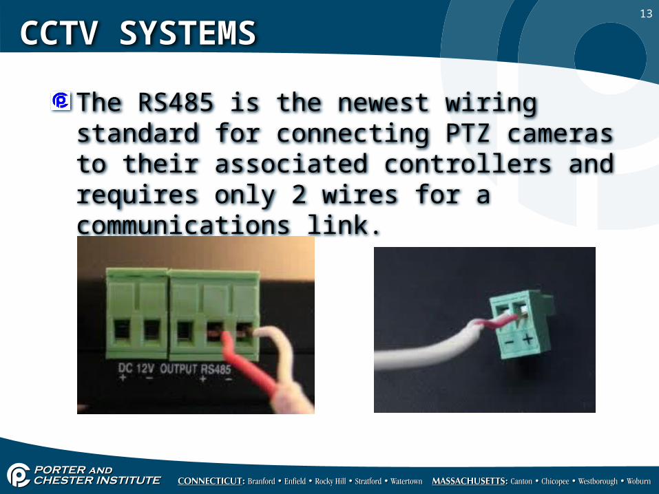
The RS485 is the newest wiring standard for connecting PTZ cameras to their associated controllers and requires only 2 wires for a communications link.

14
CCTV SYSTEMS
Most PTZ controllers will have a couple of wiring interfaces, either a RS-232 or RS-485, most installs simply use a shielded 18/2 cable that is terminate to a RS-232 adapter or wired directly into a RS-485 port.
RS-232 TO RS-485 ADAPTERS
15
CCTV SYSTEMS
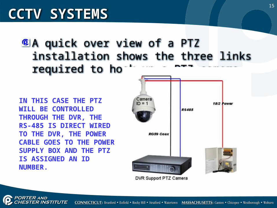
A quick over view of a PTZ installation shows the three links required to hook up a PTZ camera.
IN THIS CASE THE PTZ WILL BE CONTROLLED THROUGH THE DVR, THE RS-485 IS DIRECT WIRED TO THE DVR, THE POWER CABLE GOES TO THE POWER SUPPLY BOX AND THE PTZ IS ASSIGNED AN ID NUMBER.
16
CCTV SYSTEMS
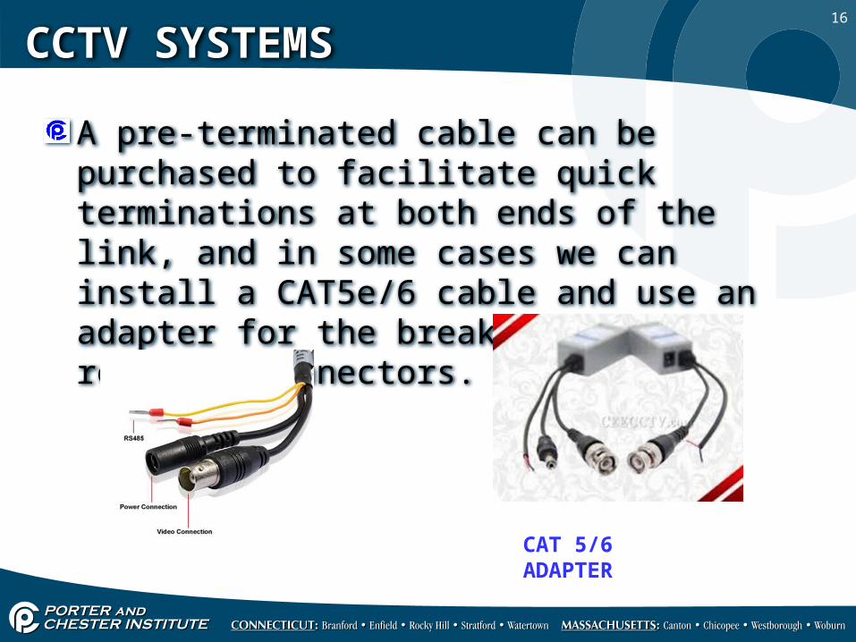
A pre-terminated cable can be purchased to facilitate quick terminations at both ends of the link, and in some cases we can install a CAT5e/6 cable and use an adapter for the break out of the required connectors.
CAT 5/6 ADAPTER
17
CCTV SYSTEMS
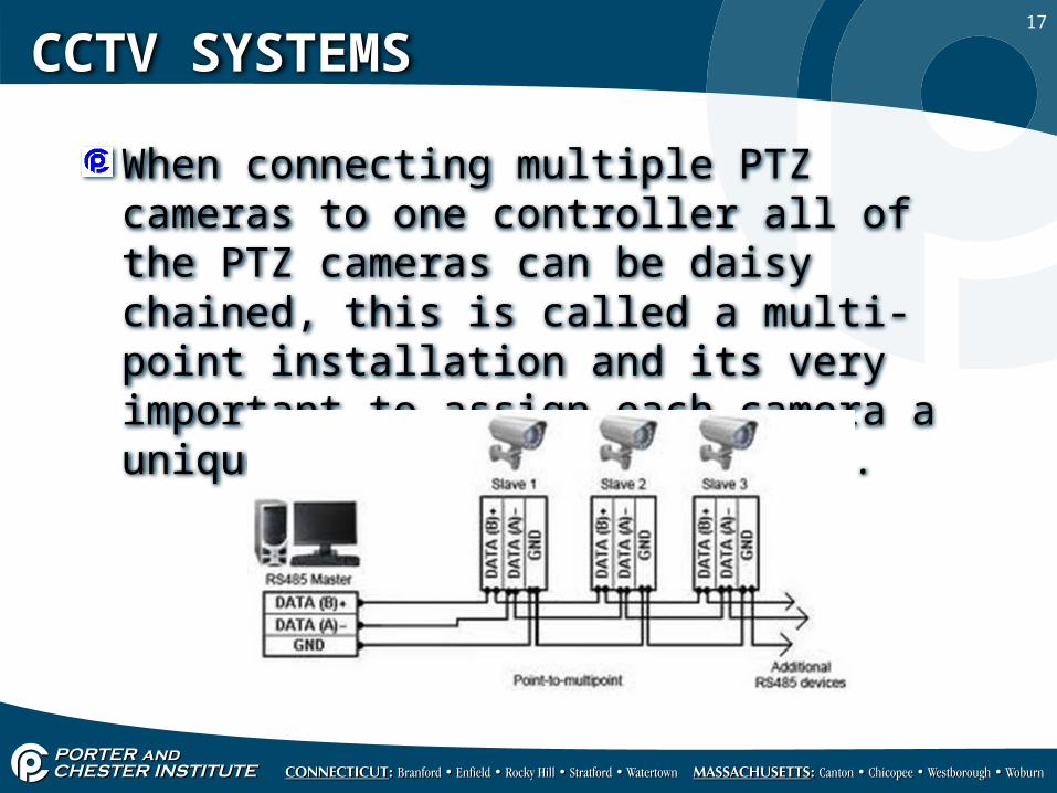
When connecting multiple PTZ cameras to one controller all of the PTZ cameras can be daisy chained, this is called a multi-point installation and its very important to assign each camera a unique ID number i.e. C1, C2 etc.
18
CCTV SYSTEMS
Most manufacturers suggest the use of a shielded cable with a drain wire, the shield and drain wire is the ground for RS-485 terminals labeled “GND”.
Here is the spec for RS-485 Data Cables: twisted pair, 24 AWG with polyethylene insulation, foil shield and tinned copper braid shield, 24 AWG tinned copper drain wire, PVC jacket, 100/500/1000 foot coil/reels
19
CCTV SYSTEMS
RS-485 cable distances extend up to 1200M or 3940 feet which is more than half a mile.
The conversion from feet to meters is 3.28, so if you divide 3940 by 3.28 you get 1201M, if you multiply 1200m by 3.28 you get 3936 feet, these numbers are rounded for ease of use.
20
CCTV SYSTEMS
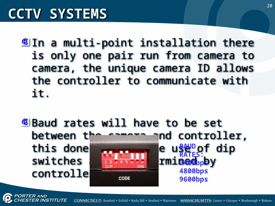
In a multi-point installation there is only one pair run from camera to camera, the unique camera ID allows the controller to communicate with it.
Baud rates will have to be set between the camera and controller, this done through the use of dip switches and is determined by controller. BAUD RATES:
2400bps 4800bps 9600bps
21
CCTV SYSTEMS
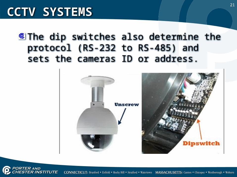
The dip switches also determine the protocol (RS-232 to RS-485) and sets the cameras ID or address.
22
CCTV SYSTEMS
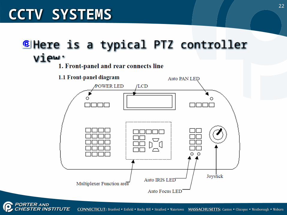
Here is a typical PTZ controller view:
23
CCTV SYSTEMS
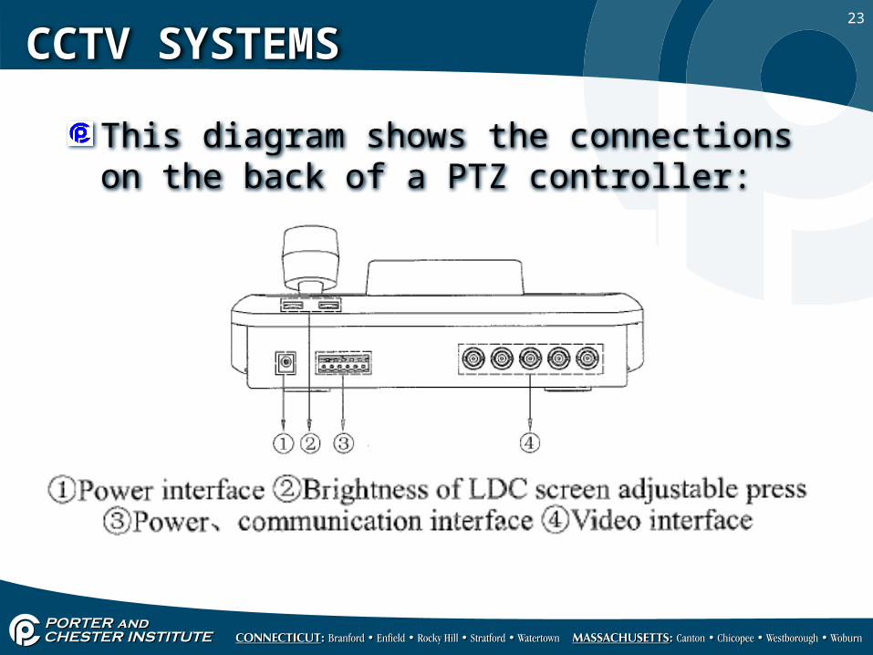
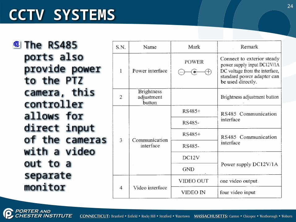
This diagram shows the connections on the back of a PTZ controller:
24
CCTV SYSTEMS
The RS485 ports also provide power to the PTZ camera, this controller allows for direct input of the cameras with a video out to a separate monitor
25
CCTV SYSTEMS
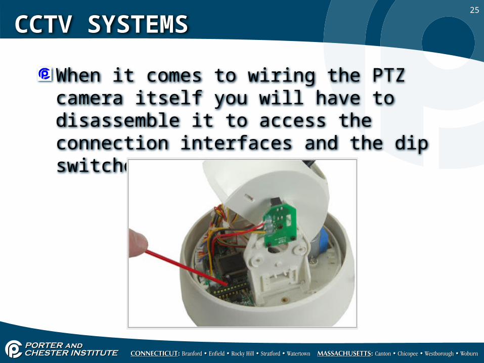
When it comes to wiring the PTZ camera itself you will have to disassemble it to access the connection interfaces and the dip switches.
26
CCTV SYSTEMS
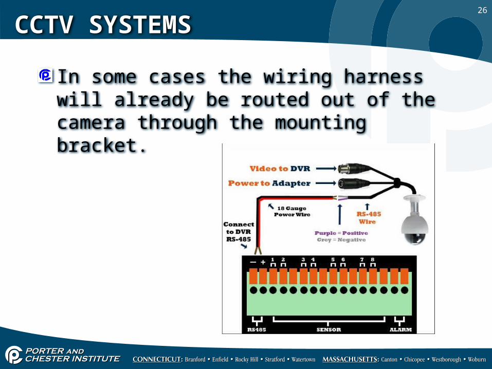
In some cases the wiring harness will already be routed out of the camera through the mounting bracket.
27
CCTV SYSTEMS
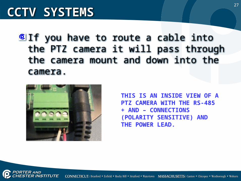
If you have to route a cable into the PTZ camera it will pass through the camera mount and down into the camera.
THIS IS AN INSIDE VIEW OF A PTZ CAMERA WITH THE RS-485 + AND – CONNECTIONS (POLARITY SENSITIVE) AND THE POWER LEAD.
28
CCTV SYSTEMS
When all connections are made it is just a matter of reading through the user’s manual for the proper operation of all the controls and functions on the controller.
NOTE: ALL CAMERAS SHOULD BE TESTED BEFORE INSTALLATION TO ENSURE IT IS PROVIDING A VIDEO IMAGE.