1 August 26, 2006Changguo Lu, Princeton University Daya Bay Collaboration Meeting, IHEP, Beijing,...
39
1 August 26, 2006 Changguo Lu, Princeton University Daya Bay Collaboration Meeting, IHEP, Beijing, 8/26-27, 2006 R&D for Daya Bay RPC system Changguo Lu Princeton University Daya Bay Collaboration Meeting IHEP, Beijing, Aug. 26-27, 2006 (Part of the R&D work in this report is the result of Collaboration with Jiawen Zhang, IHEP and Minfa Su, Gaonenkedi, Inc. for the ILC detector R&D program. )
-
date post
21-Dec-2015 -
Category
Documents
-
view
217 -
download
0
Transcript of 1 August 26, 2006Changguo Lu, Princeton University Daya Bay Collaboration Meeting, IHEP, Beijing,...

1August 26, 2006 Changguo Lu, Princeton University
Daya Bay Collaboration Meeting, IHEP, Beijing, 8/26-27, 2006
R&D for Daya Bay RPC system
Changguo Lu
Princeton University
Daya Bay Collaboration Meeting
IHEP, Beijing, Aug. 26-27, 2006
(Part of the R&D work in this report is the result of Collaboration with Jiawen Zhang, IHEP and Minfa Su, Gaonenkedi, Inc. for the
ILC detector R&D program. )

2August 26, 2006 Changguo Lu, Princeton University
Daya Bay Collaboration Meeting, IHEP, Beijing, 8/26-27, 2006
R&D for Daya Bay RPC system
Outlines
• Survey of large RPC systems in running and future experiments;
• Main goal of Daya Bay RPC R&D;
• VUV photosensitivity study;
• HF acid: production in RPC, attack the RPC;
• Super-efficiency RPC for muon veto system in Daya Bay neutrino experiment?
• Deformation of RPC under pressure;
• Cost estimation;
• Conclusions

3August 26, 2006 Changguo Lu, Princeton University
Daya Bay Collaboration Meeting, IHEP, Beijing, 8/26-27, 2006
* Part of the content is cited from “Resistive plate chambers in running and future experiments”G. Bruno, CERN, Geneva, Switzerland, Eur Phys J C 33, s1032–s1034 (2004)
(1) Survey of RPC in running and future experiments*
Experiment Operating mode
# of gaps
Gap size(mm)
Electrode material, ρ(Ω·cm)
Gas mixture(%) readout
BaBar Streamer 1 2 Oil bake.,1011~1012 Ar/R134A/Isob (60/35/5) Strips, xy
Belle Streamer 2 2 Glass, 1012~1013 Ar/R134A/Isob (30/62/8) Strips, xy
ALICE TRI Streamer 1 2 Oil bake., ~3109 Ar/R134A/Isob/SF6 (51/41/7/1) Strips, xy
ATLAS Prop. 1 2 Oil bake., ~1010 R134A/Isob/SF6 (96.7/3/0.3) Strips, xy
CMS Prop. 2 2 Oil bake., ~1010 R134A/Isob/SF6 (96/3.5/0.5) Strips, xy
OPERA Streamer 1 2 Oil bake., >51011 Ar/R134A/Isob/SF6
(75.4/20/4/0.6)Strips, xy
YBJ-ARGO Streamer 1 2 Oil bake., > 51011 Ar/R134A/Isob (15/75/10) Strips/pad
BESIII Streamer 2 2 Plain bake, 1012~1013 R134A/Isob/Ar (42/8/50) Strips, x or y
STAR TOF Prop. 5 0.22 Glass, ~1013 R134A/Isob (95/5) Pad
ALICE TOF Prop. 10 0.25 Glass, 1012~1013 R134A/Isob/SF6 (90/5/5) Pad

4August 26, 2006 Changguo Lu, Princeton University
Daya Bay Collaboration Meeting, IHEP, Beijing, 8/26-27, 2006
(2) Main Goals of the RPC R&D for Daya Bay
(my personal point of view and only focused on RPC detector technical side)
• To develop an RPC with highest possible efficiency;
• To develop an RPC with lowest noise counting rate;
• To understand the behavior of such RPC in high humidity environment;
• To optimize the readout strip geometry while to maintain the suitable timing performance and position resolution, to minimize the total number of electronics channels.

5August 26, 2006 Changguo Lu, Princeton University
Daya Bay Collaboration Meeting, IHEP, Beijing, 8/26-27, 2006
(3) UV sensitivity of the RPC electrodes
Why we concern the UV sensitivity of the RPC electrodes? Cutting down the noise rate.
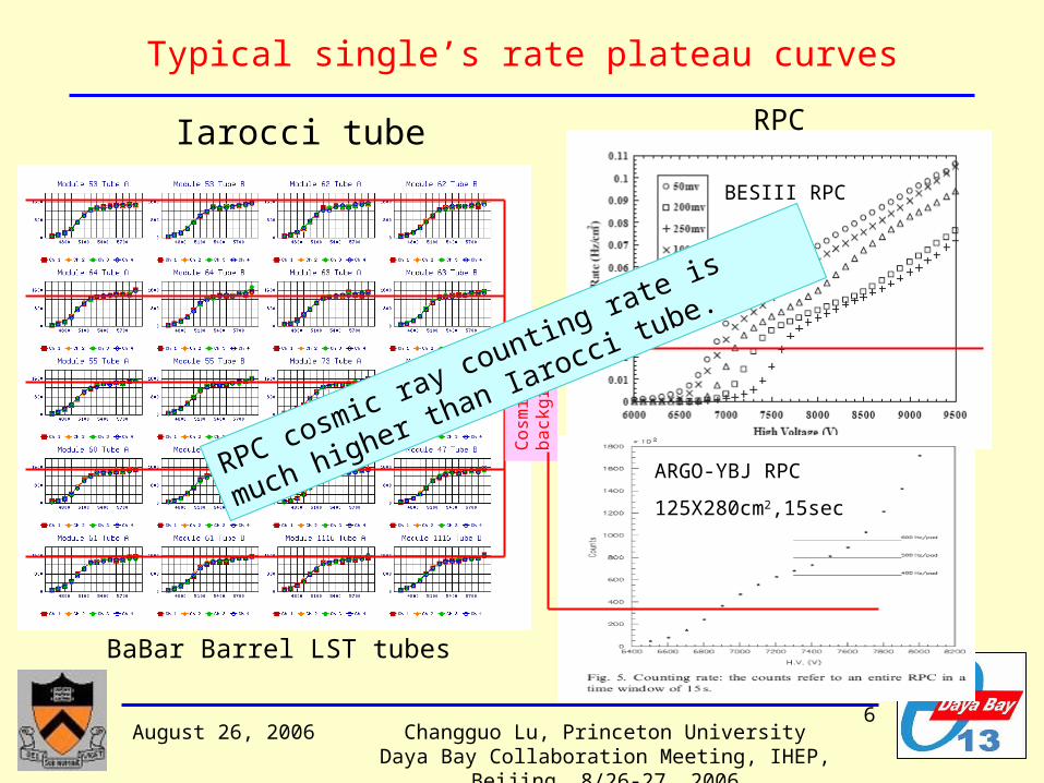
RPC always has much higher noise rate than the wire chamber. If we compare the single’s rate plateau for Iarocci tube and RPC, we’ll find:
• Iarocci tube can get beautiful single’s rate plateau curve, and its plateau counting rate is close to the cosmic ray background;
• RPC never can get real flat single’s rate plateau. Its counting rate is much higher than the cosmic ray background. (see next slide)
? ? ?Much higher electric field strength on the cathode surface and high resistive plate used for RPC.
6August 26, 2006 Changguo Lu, Princeton University
Daya Bay Collaboration Meeting, IHEP, Beijing, 8/26-27, 2006
Typical single’s rate plateau curves
Iarocci tube RPC
BESIII RPC
ARGO-YBJ RPC
125X280cm2,15sec
BaBar Barrel LST tubes
Cosm
ic r
ay
back
gro
und
RPC cosmic ray counting rate is much
higher than Iarocci tu
be.

7August 26, 2006 Changguo Lu, Princeton University
Daya Bay Collaboration Meeting, IHEP, Beijing, 8/26-27, 2006
VUV monochromator
McPherson Monochromator
UV sensitivity test device

8August 26, 2006 Changguo Lu, Princeton University
Daya Bay Collaboration Meeting, IHEP, Beijing, 8/26-27, 2006
VUV sensitivity test results
Linseed oil coating very essential for dramatically cutting down the UV sensitivity of the cathode surface.
Comparison of w/, w/o Linseed oil coating Bakelite and glass samples:

9August 26, 2006 Changguo Lu, Princeton University
Daya Bay Collaboration Meeting, IHEP, Beijing, 8/26-27, 2006
(4) HF corrosive effect on RPC electrode surface
The major component in RPC gas mix is R134A - C2H2F4.In the electrical discharge it can produce significant fluoride radicals, and further form HF. HF is notoriously chemical reactive, it can attack many different materials.
To get the sense of this corrosive action, we exposed various materials in the HF vapor environment. We measured their surface resistivity before and after the exposure.
By this we can quickly learn what kind of electrode is more robust to the HF attack.
10August 26, 2006 Changguo Lu, Princeton University
Daya Bay Collaboration Meeting, IHEP, Beijing, 8/26-27, 2006
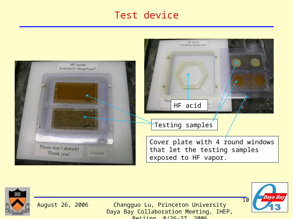
Test device
HF acid
Testing samples
Cover plate with 4 round windows that let the testing samples exposed to HF vapor.
11August 26, 2006 Changguo Lu, Princeton University
Daya Bay Collaboration Meeting, IHEP, Beijing, 8/26-27, 2006
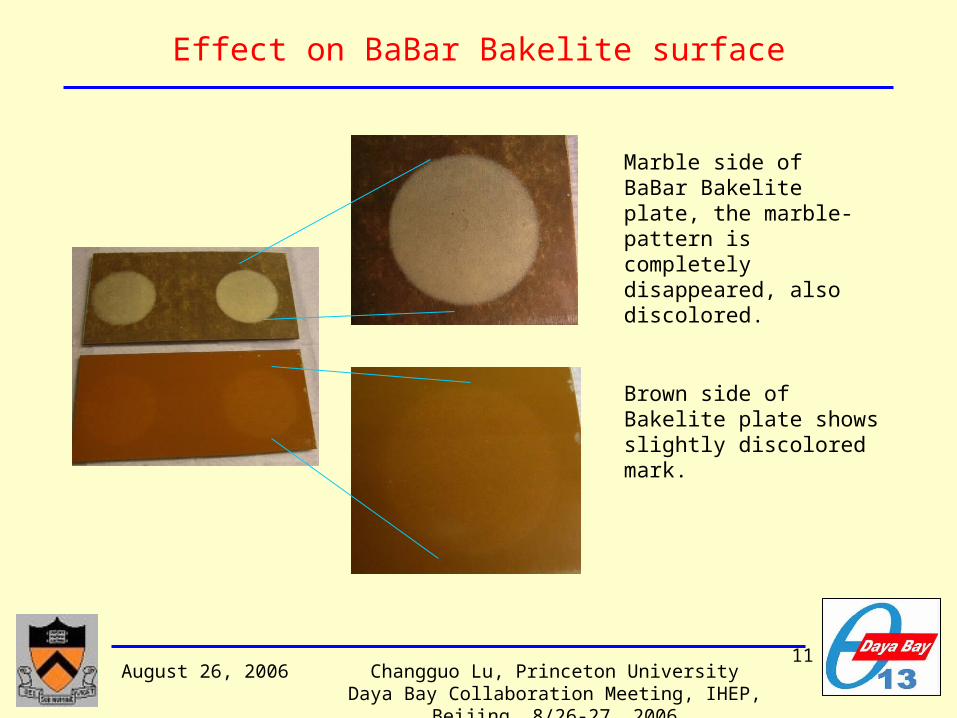
Effect on BaBar Bakelite surface
Marble side of BaBar Bakelite plate, the marble-pattern is completely disappeared, also discolored.
Brown side of Bakelite plate shows slightly discolored mark.
12August 26, 2006 Changguo Lu, Princeton University
Daya Bay Collaboration Meeting, IHEP, Beijing, 8/26-27, 2006
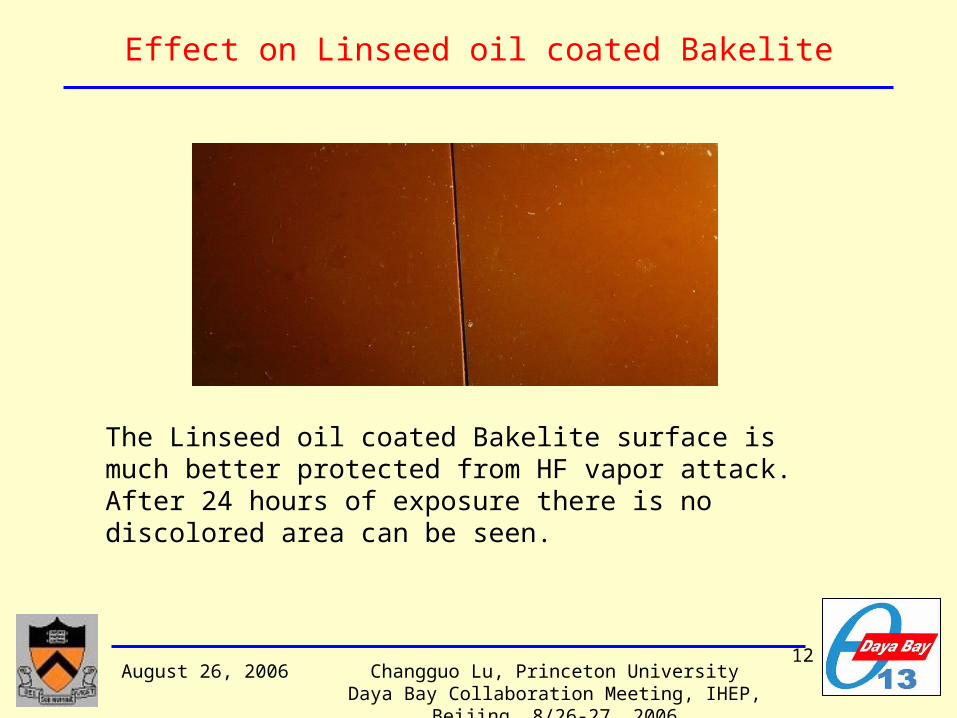
Effect on Linseed oil coated Bakelite
The Linseed oil coated Bakelite surface is much better protected from HF vapor attack. After 24 hours of exposure there is no discolored area can be seen.

13August 26, 2006 Changguo Lu, Princeton University
Daya Bay Collaboration Meeting, IHEP, Beijing, 8/26-27, 2006
Effect on BESIII Bakelite surface
Surface resistivity drops very fast in first hour of exposure.
Surface has been badly attacked by HF vapor.

14August 26, 2006 Changguo Lu, Princeton University
Daya Bay Collaboration Meeting, IHEP, Beijing, 8/26-27, 2006
Effect on various other materials
Belle’s RPC glass surface
After exposed to HF vapor for ~24 hours, the surface looks powdery fluffy.
After water rinses the surface, the fluffy “skin” is removed, the glass surface looks cracky.

15August 26, 2006 Changguo Lu, Princeton University
Daya Bay Collaboration Meeting, IHEP, Beijing, 8/26-27, 2006
Summary of the HF tests
Surface resistivity change after exposed to HF vapor
We can see that the surface resistivity reduction for IHEP Bakelite samples is ~10-7, for Linseed oil coated BaBar Bakelite samples is ~ 10-4, the glass surface is worse than IHEP Bakelite.

16August 26, 2006 Changguo Lu, Princeton University
Daya Bay Collaboration Meeting, IHEP, Beijing, 8/26-27, 2006
What we observed in BaBar RPCs?
On the inner surface of an opened BaBar RPC many white spots on the anode were found, and on the opposite cathode surface corresponding Linseed oil droplets can be seen*.
Possible explanation of these white spots:
It might be due to HF corrosion effect. In a self-sustaining sparking mode, tremendous HF can be formed on the anode surface (F- drifts towards anode), as we found in our HF corrosive test, the “marble” surface would be “bleached” and the surface becomes very rough, it would further worsen the sparking area. This action is irreversible.
*J. Va’vra, http://www-nova.fnal.gov/workshops/stanford03/transparencies/vavra_RPC_summary_2003_talk.pdf
It is not a fiction, HF corrosive effect is a
real threat to the aging of RPC!!

17August 26, 2006 Changguo Lu, Princeton University
Daya Bay Collaboration Meeting, IHEP, Beijing, 8/26-27, 2006
Production of HF in RPC
Test device for the fluoride production: fluoride probe

HF production test results
This amount of F- would be accumulated inside the chamber and attack the electrode!!
Finally the sampling solution reaches the ultimate 1.1ppm F- concentration.
(1.1-0.45=) 0.65ppm in 40CC solution of fluoride being trapped inside the chamber after accumulating Q= 22.5mC during the streamer operation.
3.86X10¹⁹ F-/C — F- adsorption rate in streamer operation.

19August 26, 2006 Changguo Lu, Princeton University
Daya Bay Collaboration Meeting, IHEP, Beijing, 8/26-27, 2006
A quick and simple test
If we pipette 90L of 48% concentration HF acid into our test container, after HF drop vaporized, it will produce ~ 1.31021 HF molecules inside the container. The total inner area of the container is 103 cm2,
1.31021/103 cm2 = 1.31018/cm2,
equivalent to a 2m2 RPC operated at 5A for 8.5 years.
The ratio of surface resistivity change (before/after) is ~ 500 to 900 for BESIII bakelite. The glass surface shows similar resistivity change.
The RPC operated underground can achieve very low dark current, such as OPERA RPC reaches 0.26A, 1/20 of 5A, therefore HF won’t cause serious trouble in Daya Bay experiment.

20August 26, 2006 Changguo Lu, Princeton University
Daya Bay Collaboration Meeting, IHEP, Beijing, 8/26-27, 2006
(5) Super-efficient RPC for neutrino experiment?
The RPC efficiency is limited by various facts:
• The geometrical dead space inside of the chamber, such as spacers, that sets the absolute upper limit of the efficiency, but this dead space is only ~1.2%;
• The fluctuation of the first ionization cluster along the track could bring in additional inefficiency to the chamber if the first cluster occurs too late to get fully developed in the gap;
• Self discharge spots in the chamber will generate extra noise rate and create excess of dead space, etc.

21August 26, 2006 Changguo Lu, Princeton University
Daya Bay Collaboration Meeting, IHEP, Beijing, 8/26-27, 2006
Solutions for further raising the efficiency
Is thicker RPC better?
From the fluctuation of the first cluster location point of view, thicker RPC certainly is better.
a b
(a) Distribution of the first cluster's location, (b) Integral distribution of (a).

22August 26, 2006 Changguo Lu, Princeton University
Daya Bay Collaboration Meeting, IHEP, Beijing, 8/26-27, 2006
Why thicker is better?
If we set the first 0.5mm is the minimum gas thickness needed to get at least one cluster, to get 100% of these clusters developed to a streamer, we need the gas gain in the rest (gap-0.5) mm to reach the Meek’s criteria(gas gain ~5x10¹⁸). Thin and thick RPC, which one is better?
Ratio: figure of merit
)5.0(
)(
mmFullGapGain
FullGapGain
a b
2mm RPC: R=300
3mm RPC: R=75
Larger R means gas gain bigger for the full gap, therefore can get more after-pulse or noise signal. Thicker gap is better.

23August 26, 2006 Changguo Lu, Princeton University
Daya Bay Collaboration Meeting, IHEP, Beijing, 8/26-27, 2006
Thicker RPC can use smaller spacer
The another advantage for the thicker RPC:
Use grooved spacer instead of spacer with lip to reduce the dead space. For 3mm spacer the grooved spacer is more realistic.
Spacer with lip Spacer with groove
Area 1 Area 70%

24August 26, 2006 Changguo Lu, Princeton University
Daya Bay Collaboration Meeting, IHEP, Beijing, 8/26-27, 2006
(6) Deformation of RPC under pressure
Young’s modulus of Bakelite plate: 8GPa; Pressure: 0.01 atm (1000Pa); Spacer distance: 10 cm;
dZmax = 73µm
Under 1 atm pressure, two electrodes will touch each other!!

25August 26, 2006 Changguo Lu, Princeton University
Daya Bay Collaboration Meeting, IHEP, Beijing, 8/26-27, 2006
In case of placing RPC under water …
Strong envelop to enclose RPC and to take the water pressure is a must.
Since RPC has a lot of spacers (every 10cm), to add a mechanically strong panel (such as honeycomb panel) outside of the RPC should have no any difficulty.
Only concern is the water-sealed feedthrough for the H.V./signal cables on the envelop.

26August 26, 2006 Changguo Lu, Princeton University
Daya Bay Collaboration Meeting, IHEP, Beijing, 8/26-27, 2006
(7) Cost estimation
Bakelite RPC: the cost estimations are based on several sources – G.T., ILC talk on RPC, BESIII.
Let the industry takes care of the mass production, physicists can concentrate on the Q.A./Q.C. of the mass production. Even Q.C. could be a heavy work load.
General Technica (Italy) Gaonenkedi (Beijing)
€200/m2 (include strip, w/o Al shielding box)(M. Piccolo, ILC Workshop, Vancouver, July, 2006)
$230/m2 (include strip and Al shielding box)(Jiawen Zhang, based on BESIII RPC)
Glass RPC: according to Jon Link’s estimation, glass cost: ~ $9.8/m2, that is 2~3 times cheaper than Bakelite. No estimation yet for the entire glass RPC.

(8) Conclusions• Because of the simplicity of the RPC technology and the knowledge accumulated in the past 25 years, the Bakelite RPC becomes a commercially available “standard” product.
• G. T. (Italy) and Gaonenkedi (Beijing) have manufactured Bakelite RPCs for several large muon systems.
• After L3, BaBar and Belle, the next big step to validate this technology will be the experiments at LHC. IHEP shall be eagerly waiting for BESIII muon system’s running report.
• Belle’s RPC is a successful story of glass RPC.
• For Daya Bay application both Bakelite and glass RPC will do the job. BESIII Bakelite RPC is a “glass-like” Bakelite RPC. Actually Its resistivity is even higher than Belle’s glass (1.1x1013 cm vs. 6.6x1012 cm).

28August 26, 2006 Changguo Lu, Princeton University
Daya Bay Collaboration Meeting, IHEP, Beijing, 8/26-27, 2006
Backup slides

29August 26, 2006 Changguo Lu, Princeton University
Daya Bay Collaboration Meeting, IHEP, Beijing, 8/26-27, 2006
ARGO-YBJ RPC test results
The new generation ARGO RPCs operated at YBJ performs very well: • Dark current: <3A at 7500V; • Single’s rate: < 500Hz/pad (Area of pad = 62X54cm2 = 3320cm2); • Efficiency > 96%; • Time resolution: 1ns; • Temperature variation inside the hall does not imply any problem to the RPC operation.

30August 26, 2006 Changguo Lu, Princeton University
Daya Bay Collaboration Meeting, IHEP, Beijing, 8/26-27, 2006
Fluctuation of the first cluster in the gas gap
Same RPC shows different maximum efficiency for sea level and 4300m a.s.l. that is a clear indication of the first cluster fluctuation in the gas gap. ARGO-YBJ RPC
∆ Eff

31August 26, 2006 Changguo Lu, Princeton University
Daya Bay Collaboration Meeting, IHEP, Beijing, 8/26-27, 2006
Sample test chamber
Multi-step gas avalanche chamber

32August 26, 2006 Changguo Lu, Princeton University
Daya Bay Collaboration Meeting, IHEP, Beijing, 8/26-27, 2006
Multi-step gas avalanche chamber
The source of the extra large dark current could come from the surface field emission or photoelectron due to UV photon absorption. If so the surface UV response would show the difference. We use a McPherson VUV monochromator to investigate this possibility.
Multi-step avalanche chamber: The first part of the chamber is a drift region, the UV-photoelectrons are drifting away from the cathode, but no gas avalanche.
The second stage – avalanche region. In this region the electric field strength is much higher than the drift region. Most of the drifting electrons would be crossing the grid mesh (90% of transparency), and entering this avalanche region. A Keithley electrometer is used here to measure the total current flows through this region.
The monochromator scans from 160nm to 250nm wavelength and records the photocurrent response curve.

33August 26, 2006 Changguo Lu, Princeton University
Daya Bay Collaboration Meeting, IHEP, Beijing, 8/26-27, 2006
RPC aging due to HF corrosion
HF surface adsorption rate in RPC: 3.86X10¹⁹ F-/C.
How many HF molecules needed to cover the entire surface of the electrode? Assume the size of HF is similar to the water molecule, ~ 310-10m. To cover 1m2 surface need 1019 HF molecules.
1C of charge can produce enough HF molecules to cover ~4m2 of surface for one layer.
If the chamber operated @ 5A current, in one year the total charge Q = 158 C, will be able to cover 4m2 area for 158 layers!!
Looks enough to affect the fragile RPC surface!

34August 26, 2006 Changguo Lu, Princeton University
Daya Bay Collaboration Meeting, IHEP, Beijing, 8/26-27, 2006
OPERA RPC dark current

35August 26, 2006 Changguo Lu, Princeton University
Daya Bay Collaboration Meeting, IHEP, Beijing, 8/26-27, 2006
Effect of the decreased surface resistivity
If the Bakelite surface resistivity dramatically decreased, and the volume resistivity keeps the same, the inner surface of the electrode looks just like a conductive layer.
In a streamer discharge the self-quenching action due to limited charge supply on the inner surface is no longer true, therefore the streamer mode operation won’t be stable.

36August 26, 2006 Changguo Lu, Princeton University
Daya Bay Collaboration Meeting, IHEP, Beijing, 8/26-27, 2006
Summary of HF corrosive study
• Bare Bakelite surface is very vulnerable to HF vapor attack. HF can destroy surface smoothness, lower surface resistivity;
• Linseed oil plays critical roll on protecting the Bakelite surface from HF attacking;
• The white spots found on anode inner surface are related to sparks, which produce F-. The produced HF corrodes the Bakelite surface, leave white spot as the evidence.

37August 26, 2006 Changguo Lu, Princeton University
Daya Bay Collaboration Meeting, IHEP, Beijing, 8/26-27, 2006
… Effect on BaBar Bakelite surface
At the very beginning of exposure the surface resistivity drops very fast, then level off.

38August 26, 2006 Changguo Lu, Princeton University
Daya Bay Collaboration Meeting, IHEP, Beijing, 8/26-27, 2006
SEM study of damaged Bakelite surface
BaBar Bakelite surface after exposed to HF vapor
Brown side:
Magnification 1000, 20 m scale can be seen in the picture
Marble pattern side:
Magnification 25600, 1 m scale can be seen in the picture

39August 26, 2006 Changguo Lu, Princeton University
Daya Bay Collaboration Meeting, IHEP, Beijing, 8/26-27, 2006
… SEM study of damaged Bakelite surfaceIHEP Bakelite surface after exposed to HF vapor
At smaller magnification ~90X, we can see 50m ~ 200 m diameter “volcano” spots.
Close-up view at the edge of one “volcano” spot.
Close-up view aimed at the center of a
“volcano”.

![Penguat Daya [2]](https://static.fdocuments.us/doc/165x107/577c83381a28abe054b41bc5/penguat-daya-2.jpg)


![Penguat Daya [3]](https://static.fdocuments.us/doc/165x107/577c83381a28abe054b41bfa/penguat-daya-3.jpg)