
1 Airship fo shizzle. Jon Anderson Team Member Hours Worked: 118 2 Team Member Jon Anderson.
33
1 Airship fo shizzle
-
Upload
leslie-simon -
Category
Documents
-
view
217 -
download
3
Transcript of 1 Airship fo shizzle. Jon Anderson Team Member Hours Worked: 118 2 Team Member Jon Anderson.

1
Airship fo shizzle

Jon AndersonTeam Member
Hours Worked: 118
2
Team Member
Jon Anderson

Agenda
3
Outline:• Vehicle selection – Military Decision Making Process [6]
• Airship Design/Performance
• Enabling technologies
• Recommendation and conclusion
• Questions3Jon Anderson

4
Problem
• Determine which aero-vehicle or combination of aero-vehicles would be best suited for a mission to Titan.
• General goals from project• specific goals (facts) stemmed from project goals
• Apply Military Decision Making Process
• Present short version

5
Recommendation

6
Facts/Assumptions
Facts: • Vehicle(s) must be aero-vehicles.• Vehicle(s) must be able to land.• Vehicle(s) must be able to carry the given science instrument payload.• Vehicle(s) must have some means of self propulsion.
Assumptions:
• All designs can survive atmospheric conditions• All designs can be packaged into a 3 m diameter aero shell• All designs will operate within 0-5 km of the surface• All designs will have some means to communicate to the orbiter or earth
7
Courses of Action
• Helicopter
• Airship
• Tilt-Rotor
• Fixed wing aircraft
• Any combination of the above vehicles

8
Screening Criteria
• Vehicles must have some basic research done from other sources.
• NASA - Airship [3]• IEEE (Institute of Electrical and Electronics Engineers) – Airship [5]• Georgia Tech - Helicopter [6]
• Detailed design out of scope of project

9
Analysis – COA screened out
After research we screened out:
• Tilt rotor
• Airplane/Glider
• Any combination with these two options.
• Ex. Airplane - airship, tilt rotor – airplane
More time – further design options

10
Evaluation/Weighing Criteria
• Mass – Lower is better – 10%
• Pre Designed Level – Higher is better – 10%
• Operational Life time – Longer is better – 15%
• Top Speed – Higher is better – 15%
• Redundancy – 1 if not available, 0 if available – 50%
• Assign 1,2,or 3 with 1 being the best in that category

11
Information Presentation
• Took all COA
• Applied screening, evaluation, weighing criteria
• Assigned number values based on 1 as the “best” and 3 being the “worst”
• Tallied findings in a table – lowest score = the best option
Example calculation for combination vehicle findings:
• Mass - highest mass – scored 3, weight 10%, score = .3• Pre-design level – second highest – scored 2, weight 10%, score = .2

12
Analysis Continued
Mass (10%)
Pre-design level (10%)
Life time (15%)
Speed (15%)
Redun. (50%)
Total
Airship .20 .1 .15 .30 .5 1.25
Helicopter .10 .3 .3 .15 .5 1.35
Combination
.30 .2 .3 .30 0 1.10
Overall Total score – Lower is better
• Combination vehicle design is the recommended COA
• Through research – divided mission of science and communication to save on overall mass.
13
Airship Design
Jon Anderson
Mission Goal: The primary mission of the airship is to function as a relay between the orbiter and the helicopter. The secondary mission of the airship is to function as a reserve platform capable of carrying out the science mission should the helicopter become inoperable.

14
Design Constraints
Jon Anderson
• Communication payload• Extra redundancy – orbiter and earth
• Science payload• Reduced
• Power subsystem• New Power systems – more power less mass.

15
Equations
Jon Anderson
Vm
TR
Mp
VgB
atm
atmHe
AirshiptianHeatm
)(
2
2
1
22
222
2
1
cos
56
10312
1:4,3
4
ab
ab
r
rb
bbabrbS
abV
Buoyancy and Volume equations [3][5]:
Shape and Surface Area equations [1][2]:

16
Equations
Jon Anderson
)2(2
1
302.1252.172.
,3/22
6/1
2.13/1
,
bVR
CVUD
R
ld
ld
dl
C
e
HullDVHull
e
HullDV
Drag and Reynolds number equations [3]:
Thrust and power available equations [5]:
fowardrequired DUPower

17
Diagram of Airship
Jon Anderson
Length 13.83 m
Width 3.45 mVolume 34.47 mBallonet volume* 8.96 m
Fins* 1x1x.7 m
Gondola* .7x.7x1.63 m
• 20% Margins
• Ballonet, fins, and gondola approx.
3
3

18
Reynolds # and Drag vs Velocity
Jon Anderson

19
Power Required/Available vs Velocity
Jon Anderson

20
Inflation time/percent vs Lift
Jon Anderson

21
Performance
Jon Anderson
Mass 195 Kg
Operational Cruse Velocity 2.5 m/s
Max Velocity 2.98 m/s
Min Climb/Descent Rate * 50 m/min
Range 36200 km
Service Ceiling 5 km
Absolute Ceiling 40 km
Estimated Lifetime * 150 days

22
Deployment
Jon Anderson
Airship inflation immediate
• Both ballonets and main envelope
• Changing ballistic coefficient
• Separate via explosive shearing bolts • Immediately max velocity

23
Enabling Technologies
Jon Anderson
Multi Mission Radioisotope Thermal Generator
• Complicated – beyond scope of design
• 5 fold increase in power• Lower mass

24
Recommendation and Conclusion
Jon Anderson
High Altitude Design
Detailed data bandwidth analysis
Hull/system optimization
Experiments
Fixed wing – tilt rotor design

25
1. Wolfram: The Mathematica Book, Wolfram Media, Inc., Fourth Edition, 1999
2. Gradshteyn/Ryzhik: Table of Integrals, Series and Products,
Academic Press, Second Printing, 1981
3. Wright, Henry S. Design of a Long Endurance Titan VTOL Vehicle. Georgia Institute of Technology.
4. Levine.S.J. NASA Space Science Vision Missions - Titan Explorer. AIAA Inc.
5. Hall. L. J. Titan Airship Explorer. IEEE Aerospace. 2001. 6. FM 101-5. Staff Organization and Operation.
References

26
Questions?
Jon Anderson

27
Backup slides - Mass
Jon Anderson
Component Mass (kg) Mass after 20% Margin (kg)Subsystem
Power 2nd Generation MMRTG 17 20.4Battery - 12 A h lithium 0.47 0.564Turbomachinery 3.94 4.728Turbine 0.9 1.08Compressor 0.9 1.08Piping 0.716 0.8592Electric Motor 1.08 1.296Alternator 1.08 1.296
Total 26.086 31.3032
Propulsion Propeller, axel, case* 5.25 6.3
Total 5.25 6.3
Science Instruments Haze and Cloud Partical Detector 3 3.6Mass Spectrometer 10 12Panchromatic Visible Light Imager 1.3 1.56
Total 14.3 17.16
Communication X-Band Omni - LGA 0.114 0.1368SDST X-up/X-down 2.7 3.24X-Band TWTA 2.1 2.52UHF Transceiver (2) 9.8 11.76UHF Omni 1.5 1.8UHF Diplexer (2) 1 1.2Additional Hardware (switches, cables, etc.) 6 7.2
Total 23.214 27.8568
ACDS Sun Sensors 0.9 1.08IMU (2) 9 10.8Radar Altimeter 4.4 5.28Antennas for Radar Altimeter 0.32 0.384Absorber for Radar Altimeter 0.38 0.456Air Data System with pressure and temperature 5 6
Total 20 24

28
Backup slides - Mass
Jon Anderson
C&DH Flight Processor 0.6 0.72
Digital I/O - CAPI Board 0.6 0.72
State of Health and Attitude Control 0.6 0.72
Power Distribution (2) 1.2 1.44
Power Control 0.6 0.72
Mother Board 0.8 0.96
Power Converters (For Integrated Avionics Unit) 0.8 0.96
Chassis 3.4 4.08
Solid State Data Recorder 1.6 1.92
Total 10.2 12.24
Structure Airship Hull 4.57 5.484
Gondola* 8.4 10.08
Tail Section: 4 Fins and attachments* 8.4 10.08
Attitude Control 4 4.8
Helium Mass (Float at 5 km) 29.95 35.94
Inflation tank for Helium* 19.17 23.004
Bayonet fans and eqipment 5.5 6.6
Total 79.99 95.988
Thermal Inflight and during operation 8.27 9.924
Total 8.27 9.924
Total Airship Dry Mass 187.31 224.772
Total Aiship Float Mass 217.26 260.712

29
Backup slides - Power
ComponentPower Required (W)
Power Required after 20% Margin (W)
Subsystem
Power 580 W Generated
Proplusion Propeller/Engine See Figure 2 See Figure 2
Total See Figure 2 See Figure 2
Bayonets Fans (2) 90 108
Total 90 108
Science Instruments Haze and Cloud Partical Detector 20
Mass Spectrometer 28Panchromatic Visible Light Imager 10
Total 58 69.6
Communication UHF Transceiver 74.88
Total 74.8 89.76
30
Backup slides - Power
Jon Anderson
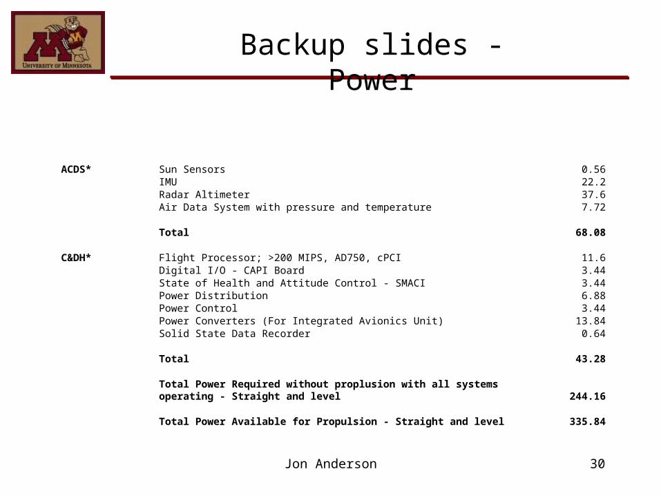
ACDS* Sun Sensors 0.56IMU 22.2Radar Altimeter 37.6Air Data System with pressure and temperature 7.72
Total 68.08
C&DH* Flight Processor; >200 MIPS, AD750, cPCI 11.6Digital I/O - CAPI Board 3.44State of Health and Attitude Control - SMACI 3.44Power Distribution 6.88Power Control 3.44Power Converters (For Integrated Avionics Unit) 13.84Solid State Data Recorder 0.64
Total 43.28
Total Power Required without proplusion with all systems operating - Straight and level 244.16
Total Power Available for Propulsion - Straight and level 335.84

31
Backup slide: COA - Airship
Mass – 490 kg
Pre Designed Level - High
Operational Life time – 150 Days
Top Speed – 3.5 m/s
Redundancy - None

32
Backup Slide: COA - Helicopter
Mass – 290 kg
Pre Designed Level - low
Operational Life time – 120 Days
Top Speed – 4.5 m/s
Redundancy - None
33
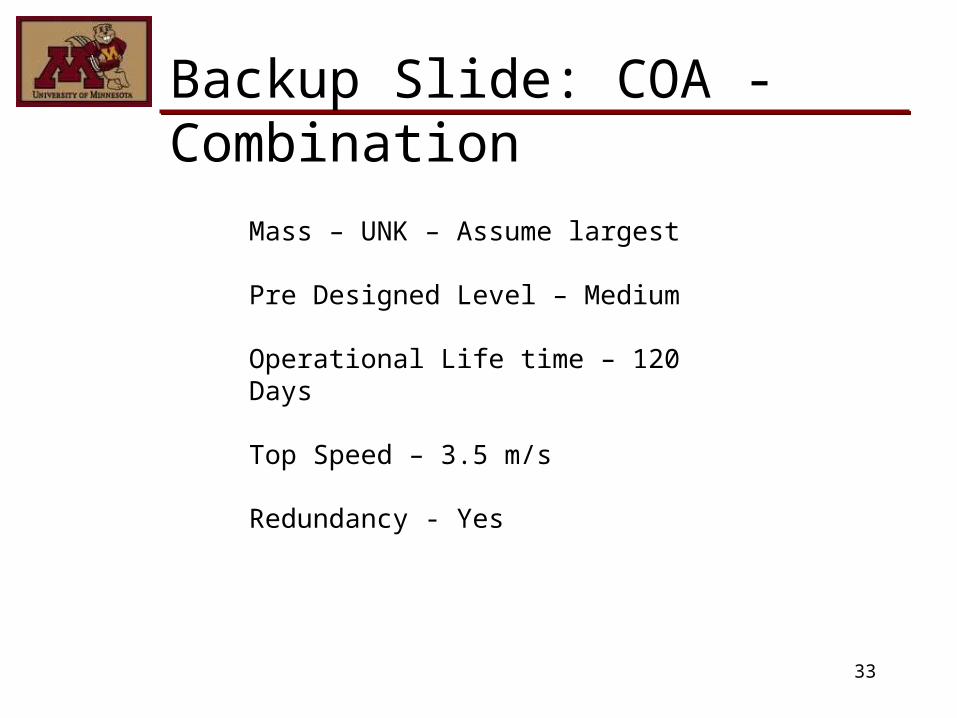
Backup Slide: COA - Combination
Mass – UNK – Assume largest
Pre Designed Level – Medium
Operational Life time – 120 Days
Top Speed – 3.5 m/s
Redundancy - Yes


![Jon Anderson · State of independence. - Vangelis, comp. . - [8] (1996) avec Jon Anderson comme Chanteur I hear you now. - Vangelis, comp. . - [6] (1996) avec Jon Anderson comme Chanteur](https://static.fdocuments.us/doc/165x107/60a7536651e5f85d1267ca53/jon-anderson-state-of-independence-vangelis-comp-8-1996-avec-jon-anderson.jpg)