1. ADDITIONAL STUDIES
37
Page 1 1. ADDITIONAL STUDIES In this project public consultation is not applicable, as project is in MIDC. Additional studies like review of social impact and public consultation were undertaken. Apart from the public consultation, major portion is dedicated to the study of hazard identification and risk assessment. It also covers the requirement for onsite and offsite disaster (natural and manmade) preparedness plan including emergency management plan. Social Impact Assessment Studies (SIA) Rehabilitation and Resettlement (R & R) and Social Impact Assessment (SIA) studies have not found any relevance for the proposed project site as there would not be any temporary or permanent displacement of the personnel or goods as the proposed project will be located in MIDC, Paithan. Hence, no R & R and SIA studies or plan were undertaken for the particular site. The nearest residential settlement is at Yashwant Nagar- 0.84 km (NE), Mudhalwadi- 1.40 km (S), Paithan- 7.72 km (SE), Dhangaon-3.95 km (NW) from the site. Proposed project activity will not cause any negative impacts on the environment and on the society as it will increase the direct and indirect job opportunities along with indirect work to the local people residing in the area. There will be some development of secondary service market near the site which will be beneficial to the local economy. 1.1. Introduction - M/s Shalini Organics Pvt. Ltd is Green Field project. The project will be executed at Paithan MIDC Plot No. D- 10, Taluka Paithan Dist. Aurangabad, Maharashtra. As the proposed project comes under the schedule (f) - Synthetic Organic Chemicals industry (EIA Notification dated 14 th September 2006) Company is classified as small-Scale Industry under Red Category by Maharashtra Pollution Control Board. Due to change in economic scenario, it is time to change as per market requirements and bring out the products which gives optimum results for company as well as society. Now a day’s, rate of human health diseases is increasing rapidly. Medical treatment with the help of drugs/medicines is a common practice in which medicines/drugs play an important role in recovering the health & control the diseases. Pharmaceutical industries require raw materials in the form of synthetic chemicals, bulk drugs and intermediates to prepare final products as medicine. Bulk drug intermediates are the active raw materials used in drug that are useful as therapeutic agents. Therefore, proposed manufacturing of various API and Intermediates has a vital importance. The raw materials required for proposed activity will be procured from local market. 1.2. Objectives and Scope of work The purpose of carrying out the Risk Analysis is to analyze the hazards & Risks, nature & impact of hazards due to handling & storage of hazardous products. The analysis aims at quantitative evaluation of the risk involved due to location & operation of the Plant and also to ascertain that the risk is within its acceptable limits or not. The finding results into recommendations for minimization of the existing levels of risk. All the important aspects of the Manufacture, Storage & Import of Hazardous Chemicals Rules, 2000 and relevant Guidelines would be used as directives in conducting the Risk analysis.
Transcript of 1. ADDITIONAL STUDIES

Page 1
1. ADDITIONAL STUDIES
In this project public consultation is not applicable, as project is in MIDC. Additional studies like review of social impact and public consultation were undertaken. Apart from the public consultation, major portion is dedicated to the study of hazard identification and risk assessment. It also covers the requirement for onsite and offsite disaster (natural and manmade) preparedness plan including emergency management plan.
Social Impact Assessment Studies (SIA)
Rehabilitation and Resettlement (R & R) and Social Impact Assessment (SIA) studies have not found any relevance for the proposed project site as there would not be any temporary or permanent displacement of the personnel or goods as the proposed project will be located in MIDC, Paithan. Hence, no R & R and SIA studies or plan were undertaken for the particular site. The nearest residential settlement is at Yashwant Nagar- 0.84 km (NE), Mudhalwadi- 1.40 km (S), Paithan- 7.72 km (SE), Dhangaon-3.95 km (NW) from the site. Proposed project activity will not cause any negative impacts on the environment and on the society as it will increase the direct and indirect job opportunities along with indirect work to the local people residing in the area. There will be some development of secondary service market near the site which will be beneficial to the local economy.
1.1. Introduction -
M/s Shalini Organics Pvt. Ltd is Green Field project. The project will be executed at Paithan MIDC Plot No. D-10, Taluka Paithan Dist. Aurangabad, Maharashtra. As the proposed project comes under the schedule (f) - Synthetic Organic Chemicals industry (EIA Notification dated 14th September 2006) Company is classified as small-Scale Industry under Red Category by Maharashtra Pollution Control Board.
Due to change in economic scenario, it is time to change as per market requirements and bring out the products which gives optimum results for company as well as society. Now a day’s, rate of human health diseases is
increasing rapidly. Medical treatment with the help of drugs/medicines is a common practice in which medicines/drugs play an important role in recovering the health & control the diseases. Pharmaceutical industries require raw materials in the form of synthetic chemicals, bulk drugs and intermediates to prepare final products as medicine. Bulk drug intermediates are the active raw materials used in drug that are useful as therapeutic agents. Therefore, proposed manufacturing of various API and Intermediates has a vital importance. The raw materials required for proposed activity will be procured from local market.
1.2. Objectives and Scope of work
The purpose of carrying out the Risk Analysis is to analyze the hazards & Risks, nature & impact of hazards due to handling & storage of hazardous products. The analysis aims at quantitative evaluation of the risk involved due to location & operation of the Plant and also to ascertain that the risk is within its acceptable limits or not. The finding results into recommendations for minimization of the existing levels of risk.
All the important aspects of the Manufacture, Storage & Import of Hazardous Chemicals Rules, 2000 and relevant Guidelines would be used as directives in conducting the Risk analysis.
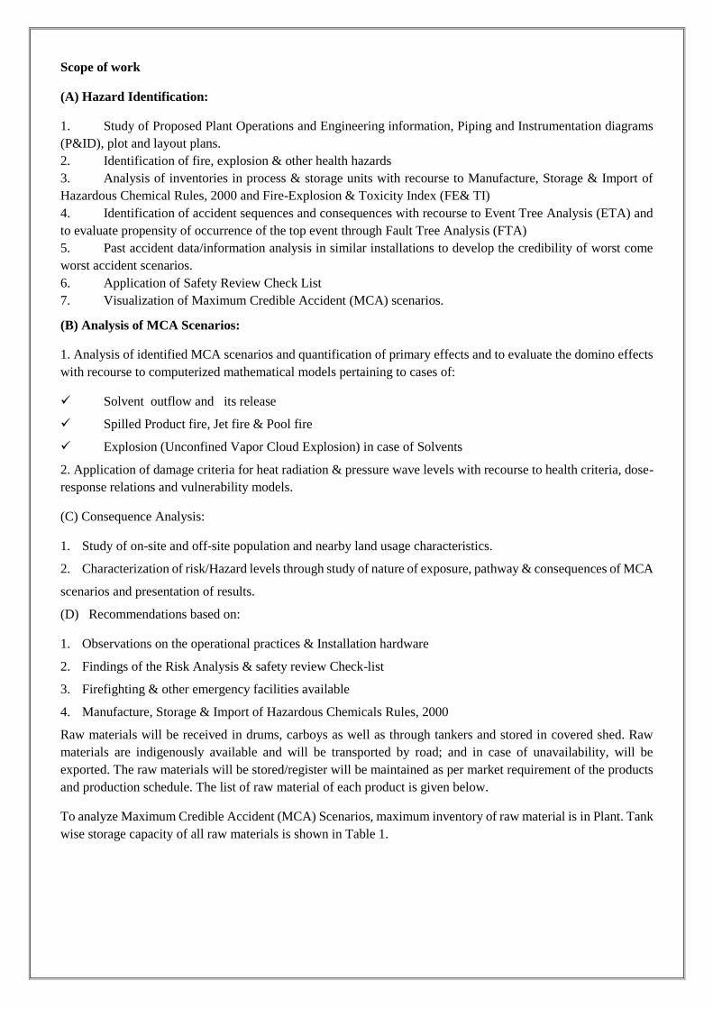
Scope of work
(A) Hazard Identification:
1. Study of Proposed Plant Operations and Engineering information, Piping and Instrumentation diagrams (P&ID), plot and layout plans. 2. Identification of fire, explosion & other health hazards 3. Analysis of inventories in process & storage units with recourse to Manufacture, Storage & Import of Hazardous Chemical Rules, 2000 and Fire-Explosion & Toxicity Index (FE& TI) 4. Identification of accident sequences and consequences with recourse to Event Tree Analysis (ETA) and to evaluate propensity of occurrence of the top event through Fault Tree Analysis (FTA) 5. Past accident data/information analysis in similar installations to develop the credibility of worst come worst accident scenarios. 6. Application of Safety Review Check List 7. Visualization of Maximum Credible Accident (MCA) scenarios.
(B) Analysis of MCA Scenarios:
1. Analysis of identified MCA scenarios and quantification of primary effects and to evaluate the domino effects with recourse to computerized mathematical models pertaining to cases of:
Solvent outflow and its release
Spilled Product fire, Jet fire & Pool fire
Explosion (Unconfined Vapor Cloud Explosion) in case of Solvents
2. Application of damage criteria for heat radiation & pressure wave levels with recourse to health criteria, dose-response relations and vulnerability models.
(C) Consequence Analysis:
1. Study of on-site and off-site population and nearby land usage characteristics.
2. Characterization of risk/Hazard levels through study of nature of exposure, pathway & consequences of MCA
scenarios and presentation of results.
(D) Recommendations based on:
1. Observations on the operational practices & Installation hardware
2. Findings of the Risk Analysis & safety review Check-list
3. Firefighting & other emergency facilities available
4. Manufacture, Storage & Import of Hazardous Chemicals Rules, 2000
Raw materials will be received in drums, carboys as well as through tankers and stored in covered shed. Raw materials are indigenously available and will be transported by road; and in case of unavailability, will be exported. The raw materials will be stored/register will be maintained as per market requirement of the products and production schedule. The list of raw material of each product is given below.
To analyze Maximum Credible Accident (MCA) Scenarios, maximum inventory of raw material is in Plant. Tank wise storage capacity of all raw materials is shown in Table 1.
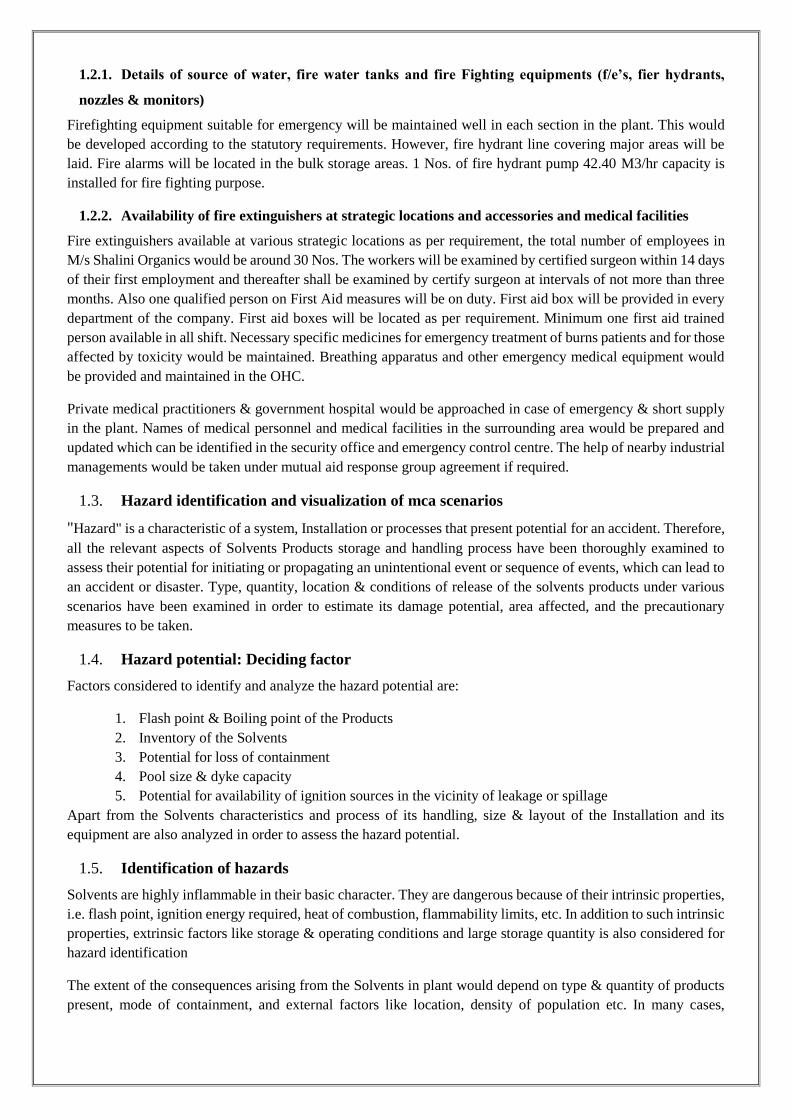
1.2.1. Details of source of water, fire water tanks and fire Fighting equipments (f/e’s, fier hydrants,
nozzles & monitors)
Firefighting equipment suitable for emergency will be maintained well in each section in the plant. This would be developed according to the statutory requirements. However, fire hydrant line covering major areas will be laid. Fire alarms will be located in the bulk storage areas. 1 Nos. of fire hydrant pump 42.40 M3/hr capacity is installed for fire fighting purpose.
1.2.2. Availability of fire extinguishers at strategic locations and accessories and medical facilities
Fire extinguishers available at various strategic locations as per requirement, the total number of employees in M/s Shalini Organics would be around 30 Nos. The workers will be examined by certified surgeon within 14 days of their first employment and thereafter shall be examined by certify surgeon at intervals of not more than three months. Also one qualified person on First Aid measures will be on duty. First aid box will be provided in every department of the company. First aid boxes will be located as per requirement. Minimum one first aid trained person available in all shift. Necessary specific medicines for emergency treatment of burns patients and for those affected by toxicity would be maintained. Breathing apparatus and other emergency medical equipment would be provided and maintained in the OHC.
Private medical practitioners & government hospital would be approached in case of emergency & short supply in the plant. Names of medical personnel and medical facilities in the surrounding area would be prepared and updated which can be identified in the security office and emergency control centre. The help of nearby industrial managements would be taken under mutual aid response group agreement if required.
1.3. Hazard identification and visualization of mca scenarios
"Hazard" is a characteristic of a system, Installation or processes that present potential for an accident. Therefore, all the relevant aspects of Solvents Products storage and handling process have been thoroughly examined to assess their potential for initiating or propagating an unintentional event or sequence of events, which can lead to an accident or disaster. Type, quantity, location & conditions of release of the solvents products under various scenarios have been examined in order to estimate its damage potential, area affected, and the precautionary measures to be taken.
1.4. Hazard potential: Deciding factor
Factors considered to identify and analyze the hazard potential are:
1. Flash point & Boiling point of the Products 2. Inventory of the Solvents 3. Potential for loss of containment 4. Pool size & dyke capacity 5. Potential for availability of ignition sources in the vicinity of leakage or spillage
Apart from the Solvents characteristics and process of its handling, size & layout of the Installation and its equipment are also analyzed in order to assess the hazard potential.
1.5. Identification of hazards
Solvents are highly inflammable in their basic character. They are dangerous because of their intrinsic properties, i.e. flash point, ignition energy required, heat of combustion, flammability limits, etc. In addition to such intrinsic properties, extrinsic factors like storage & operating conditions and large storage quantity is also considered for hazard identification
The extent of the consequences arising from the Solvents in plant would depend on type & quantity of products present, mode of containment, and external factors like location, density of population etc. In many cases,

realization of hazard and its potential also depend on prevailing meteorological conditions and availability of ignition source. Thus, most serious consequences would arise from a large inventory of Solvent surrounded by a densely populated area.
Flammability Classification Criteria:
Table 1.1 Details of Flamibility
S.N. Flammability Class Flash point (°C) 1 Class A Flammable Liquid FP < 23 2 Class B Flammable Liquid 23 > FP <65
Solvents require interaction with air or oxygen for its hazard to be realized. Under certain circumstances, vapors of the products when mixed with air may be explosive especially in confined spaces. Following methods of hazard identification have been employed in this study:
1. Characterization of major hazardous units based on Manufacture, Storage and Import of Hazardous Chemicals Rules, Government of India, 2000; referred here as MSIHC Rules. 2. Identification of hazardous installations based on relative ranking technique, viz. Dow's Fire Explosion Index and Mond's Toxicity Index (FEI & TI)
1.5.1. M/s Shalini organics as per MSIHC rules, 2000
Major hazard installations in the country have been identified & characterized by MSIHC Rules, 2000. The rules employ certain criteria based on flammable, explosive & toxic properties and quantity of the chemicals. Indicative criteria adopted in the MSIHC Rules, 2000 and description of applicable provisions of the rules is given in Appendix I.
As per provisions of the MSIHC Rules, 2000 quantity of Solvent Storage at the Installations has been analyzed and the applicable rules are identified based on the type of solvents, quantity of storage and the threshold quantity given in the rules. Applicable regulations of MSIHC Rules, 2000 to the Installations are identified in the following Table7.2
All solvents in plant fall under the category of isolated storage, which comes under schedule 3 Part II of MSIHC Rules. Threshold quantities and applicability of various rules are as follows:

Table 1.2 Applicability of MSIHC Rule
Sr. No.
Product Storage Capacity
Threshold Quantity (MT) as per MSIHC Rules*
Applicable Rules Class In Ton For Rules 5,7 to 9
& 13 to 15 For Rules 10
to 12
1 Toluene 5 1,000 5000 2(e) (i)(iii), 2(h)(i), 3, 4,5,7
to 9, 10 to 15
2 Methanol 20 1,000 5000 2(e) (i)(iii), 2(h)(i), 3, 4,5,7
to 9, 10 to 15
3 Isopropyl Alcohol
- 1,000 5000 2(e) (i)(iii), 2(h)(i), 3, 4,5,7
to 9, 10 to 15
4 Acetone 5 1,000 5000 2I (i)(iii), 2(h)(i), 3, 4,5,7 to
9, 10 to 15
5 Iso-propanol 10 1,000 5000 2I (i)(iii), 2(h)(i), 3, 4,5,7 to
9, 10 to 15 6 N-Propanol 10 1000 5000
7 Ethyl Acetate 5 1,000 5000 2I (i)(iii), 2(h)(i), 3, 4,5,7 to
9, 10 to 15
8 Hexane - 1,000 5000 2I (i)(iii), 2(h)(i), 3, 4,5,7 to
9, 10 to 15
9 Acetonitrile - 350 5000 2I (i)(iii), 2(h)(i), 3, 4,5,7 to
9, 10 to 15
10 HSD 200 lit 5000 10000 2I (i)(iii), 2(h)(i), 3, 4,5,7 to
9, 10 to 15
Rule 2: Identification for Existence of “Hazardous Chemicals”:
"Hazardous chemicals" are existing in the Proposed Plant as per rule 2(e)(i) & 2(e)(ii), Solvent existing at the Installation are covered under Schedule I(b)(ii) "Industrial Activity" carried out in the Installation involves operation / processes having hazardous chemicals and includes their on-site storage & transportation as per Rule 2(h) (i). “Isolated storage” of Solvent is covered in schedule 2.
Rule 3: Duties of the Government Authorities:
Duties of the Government Authorities as per schedule V.
Rule 4: General Responsibility of Occupier:
As "hazardous chemicals" exist in the Installation, the occupier has to provide evidence to show that he has:
Identified the major accident hazards & Taken adequate steps to: Prevent such major accidents and to limit their consequences to persons & environment. Provide information, training and safety equipments, including antidotes to the persons working on site to ensure their safety
Rule 5: Notification of Major Accidents:
Notification of "Major Accidents" in the format given in Schedule 6 to Chief Inspector of factories and to other authorities as listed in Schedule V.
Rule 7: Notification of Site:
Notification of site and updated information of the modifications to the competent authority as per Schedule VII.

Rule 8: Updating of the Site Notification Following Changes in the Threshold Quantity:
Any change in the “threshold quantity” (storage quantity) is to be notified to the competent authority.
Rule 9: Transitional Provision:
Transitional Provision for the existing activity
Rule 10: Safety Reports:
Preparation of Safety report by the occupier & to carry out an independent safety audit once in a year.
Rule 11: Updating of report under rule 10:
Updating of safety reports based on modification.
Rule 12: Requirement for further information to be sent to the authority:
Further information on safety reports to the authority.
Rule 13: Preparation to On-site emergency plan by the occupier:
Preparation of onsite emergency plan by the occupier & to conduct mock drill will take once in every 6 months.
Rule 14: Preparation of Off-site emergency plan by the occupier:
Preparation of offsite emergency plan by the occupier & to conduct mock drill will take once in every Year.
Rule 15: Information to be given to persons liable to be affected by a major accident
Rule 16: Collection, Development and Dissemination of Information on "Hazardous Chemicals" Employed by the Occupier
Material Safety Data Sheet is to be prepared as per Schedule IX Every container of hazardous chemical should be labeled or marked to identify Contents of the container The name and the address of the manufacturer Physical, Chemical and Toxicological data as per the criteria given in Schedule I : Part I Rule 18: Import of Hazardous Chemicals
(1) The rule is applicable as “hazardous chemicals” as per Schedule 1 Part I (b) (ii) exist in the Installation.
(2) To provide timely information to various Govt. Authorities listed in Schedule V: Name & address of the company receiving the consignment in India The port of entry in India Mode of transport from exporting country to India The quantity of chemicals being imported Complete product safety information
1.5.2. Fire Explosion & Toxicity Index (FEI & TI) Analysis for Shalini organics
Introduction & Objectives: The most widely used relative ranking hazard indices are Dow chemical Company's Fire Explosion Index (FEI) and Mond's Toxicity Index (TI). They are commonly together referred to as Fire Explosion and Toxicity Index (FEI & TI).
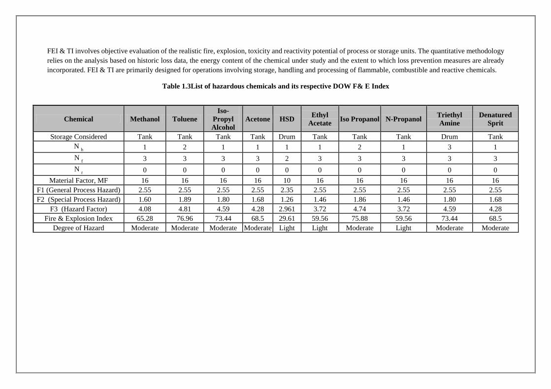
FEI & TI involves objective evaluation of the realistic fire, explosion, toxicity and reactivity potential of process or storage units. The quantitative methodology relies on the analysis based on historic loss data, the energy content of the chemical under study and the extent to which loss prevention measures are already incorporated. FEI & TI are primarily designed for operations involving storage, handling and processing of flammable, combustible and reactive chemicals.
Table 1.3List of hazardous chemicals and its respective DOW F& E Index
Chemical Methanol Toluene Iso-
Propyl Alcohol
Acetone HSD Ethyl Acetate Iso Propanol N-Propanol Triethyl
Amine Denatured
Sprit
Storage Considered Tank Tank Tank Tank Drum Tank Tank Tank Drum Tank N
h 1 2 1 1 1 1 2 1 3 1
N f 3 3 3 3 2 3 3 3 3 3
N r 0 0 0 0 0 0 0 0 0 0
Material Factor, MF 16 16 16 16 10 16 16 16 16 16 F1 (General Process Hazard) 2.55 2.55 2.55 2.55 2.35 2.55 2.55 2.55 2.55 2.55 F2 (Special Process Hazard) 1.60 1.89 1.80 1.68 1.26 1.46 1.86 1.46 1.80 1.68
F3 (Hazard Factor) 4.08 4.81 4.59 4.28 2.961 3.72 4.74 3.72 4.59 4.28 Fire & Explosion Index 65.28 76.96 73.44 68.5 29.61 59.56 75.88 59.56 73.44 68.5
Degree of Hazard Moderate Moderate Moderate Moderate Light Light Moderate Light Moderate Moderate
Page 8
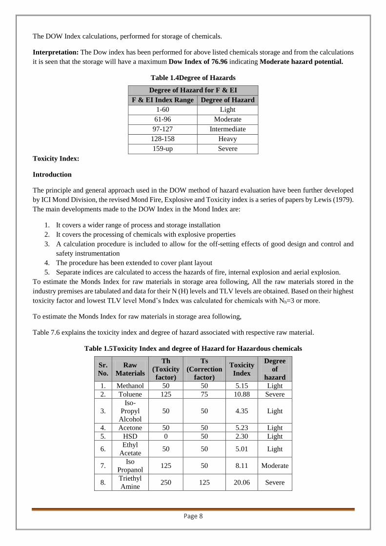
The DOW Index calculations, performed for storage of chemicals.
Interpretation: The Dow index has been performed for above listed chemicals storage and from the calculations it is seen that the storage will have a maximum Dow Index of 76.96 indicating Moderate hazard potential.
Table 1.4Degree of Hazards
Degree of Hazard for F & EI F & EI Index Range Degree of Hazard
1-60 Light 61-96 Moderate 97-127 Intermediate
128-158 Heavy 159-up Severe
Toxicity Index:
Introduction
The principle and general approach used in the DOW method of hazard evaluation have been further developed by ICI Mond Division, the revised Mond Fire, Explosive and Toxicity index is a series of papers by Lewis (1979). The main developments made to the DOW Index in the Mond Index are:
1. It covers a wider range of process and storage installation 2. It covers the processing of chemicals with explosive properties 3. A calculation procedure is included to allow for the off-setting effects of good design and control and
safety instrumentation 4. The procedure has been extended to cover plant layout 5. Separate indices are calculated to access the hazards of fire, internal explosion and aerial explosion.
To estimate the Monds Index for raw materials in storage area following, All the raw materials stored in the industry premises are tabulated and data for their N (H) levels and TLV levels are obtained. Based on their highest toxicity factor and lowest TLV level Mond’s Index was calculated for chemicals with Nh=3 or more.
To estimate the Monds Index for raw materials in storage area following,
Table 7.6 explains the toxicity index and degree of hazard associated with respective raw material.
Table 1.5Toxicity Index and degree of Hazard for Hazardous chemicals
Sr. No.
Raw Materials
Th (Toxicity factor)
Ts (Correction
factor)
Toxicity Index
Degree of
hazard 1. Methanol 50 50 5.15 Light 2. Toluene 125 75 10.88 Severe
3. Iso-
Propyl Alcohol
50 50 4.35 Light
4. Acetone 50 50 5.23 Light 5. HSD 0 50 2.30 Light
6. Ethyl
Acetate 50 50 5.01 Light
7. Iso
Propanol 125 50 8.11 Moderate
8. Triethyl Amine
250 125 20.06 Severe

Sr. No.
Raw Materials
Th (Toxicity factor)
Ts (Correction
factor)
Toxicity Index
Degree of
hazard
9. N-
Propanol 50 50 5.01 Light
10. Denatured
Sprit 50 50 5.23 Light
1.6. Visualization of MCA Scenarios
1.6.1. Introduction
A Maximum Credible Accident (MCA) can be characterized as an accident with a maximum damage potential, which is believed to be credible. For selection of a MCA scenario following factors have been taken into account.
* Flammability of the Products
* Quantity of Products present in the tank
*Process or storage conditions such as temperature, pressure, flow, mixing and presence of incompatible materials
In addition to the above factors, location of the unit with respect to adjacent establishment has been taken into consideration to account for the potential of escalation of an accident. This phenomenon is known as the domino or secondary effect. In order to visualize MCA scenarios Chemical Inventory Analysis, Event Tree Analysis and Past Accident Review have been employed.
1.6.2. Chemical InventoryAnalysis
Maximum inventory of Solvents in storage tanks has been considered.
1.6.3. Identification of Chemical Release & Accident Scenarios
Credible accident scenarios for the Installation have been divided into following categories according to the mode of release of Solvent, physical effects and the resulting damages:
Pool fire (release of chemicals from a tank, forming a pool within the dyke/fire wall and catching fire) Jet fire (leakage of chemicals from a tank/pipe/pump/joints and the products stream catching fire) Spilled Product Fire Unconfined Vapor Cloud Explosion (UVCE) as a secondary effect of above mentioned scenarios
1.6.4. Even tree analysis to define outcome of release
ETA diagram for various modes of failures of storage tank/ pump/ pipe/ joints for storage of chemicals have been developed for conditions such as overfilling, over-pressure and remote incidents like missile, lightening or bomb attack and earthquake. The resultant ruptures of vessels or leak incidents have been identified with possible outcomes of such incidents. These are depicted in Figure 7.3.
Scenarios pertaining to leakage & spillage are most credible in such plant.
1.6.5. Short listing of mca scenarios
Based on the hazard identification and comparing the nature of installation with that from past accidents in similar units, a final short list of MCA scenarios for the Installation has been made, which are given in following Table. These are the maximum credible accidents, which may occur, in the respective unit.
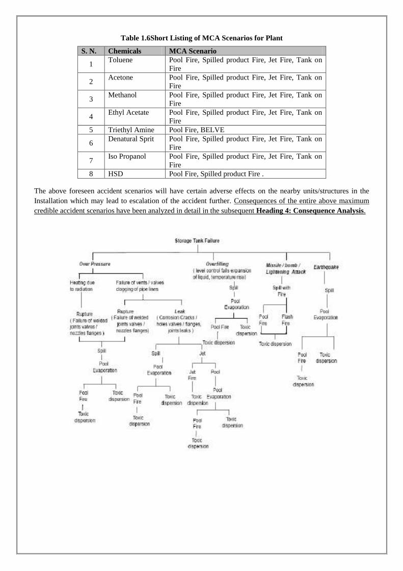
Table 1.6Short Listing of MCA Scenarios for Plant
S. N. Chemicals MCA Scenario
1 Toluene Pool Fire, Spilled product Fire, Jet Fire, Tank on
Fire
2 Acetone Pool Fire, Spilled product Fire, Jet Fire, Tank on
Fire
3 Methanol Pool Fire, Spilled product Fire, Jet Fire, Tank on
Fire
4 Ethyl Acetate Pool Fire, Spilled product Fire, Jet Fire, Tank on
Fire 5 Triethyl Amine Pool Fire, BELVE
6 Denatural Sprit Pool Fire, Spilled product Fire, Jet Fire, Tank on
Fire
7 Iso Propanol Pool Fire, Spilled product Fire, Jet Fire, Tank on
Fire 8 HSD Pool Fire, Spilled product Fire .
The above foreseen accident scenarios will have certain adverse effects on the nearby units/structures in the Installation which may lead to escalation of the accident further. Consequences of the entire above maximum credible accident scenarios have been analyzed in detail in the subsequent Heading 4: Consequence Analysis.

Figure 1.1Event Tree Analysis of failure of Atmospheric Storage tank of Flammable Liquids
HAZARDS & DAMAGE CRITERIA OF MATERIALS
DEFINITIONS:
The release of flammable liquid can lead to different types of fire or explosion scenarios. These depend on the material released, mechanism of release, temperature and pressure of the material and the point of ignition. Types of flammable effects are as follows.
Hazards associated with Flammable materials
a. Pool fire:
The released flammable material which is a liquid stored below its normal boiling point, will collect in a pool. The geometry of the pool will be dictated by the surroundings. If the liquid is stored under pressure above its normal boiling point, then a fraction of the liquid will flash into vapor and the remaining portion will form a pool in the vicinity of the release point. Once sustained combustion is achieved, liquid fires quickly reach steady state burning. The heat release rate is a function of the liquid surface area exposed to air. An unconfined spill will tend to have thin fuel depth (typically less than 5 mm) which will result in slower burning rates. A confined spill is limited by the boundaries (e.g. a dyke area) and the depth of the resulting pool is greater than that for an unconfined spill.

b. Flash fire:
It occurs when a vapor cloud of flammable material burns. The cloud is typically ignited on the edge and burns towards the release point. The duration of flash fire is very short (seconds), but it may continue as jet fire if the release continues. The overpressures generated by the combustion are not considered significant in terms of damage potential to persons, equipment or structures. The major hazard from flash fire is direct flame impingement. Typically, the burn zone is defined as the area the vapor cloud covers out to half of the LFL. This definition provides a conservative estimate, allowing for fluctuations in modeling. Even where the concentration may be above the UFL, turbulent induced combustion mixes the material with air and results in flash fire.
c. Jet Fire:
Jet flames are characterized as high-pressure release of gas from limited openings (e.g., due to small leak in a vessel or broken drain valve). Boiling liquid expanding vapor explosion (BLEVE) or fireball: A fireball is an intense spherical fire resulting from a sudden release of pressurized liquid or gas that is immediately ignited. The best-known cause of a fireball is a boiling liquid expanding vapor explosion (BLEVE). Fireball duration is typically 5 – 20 seconds
d. Unconfined Vapor Cloud Explosion (UVCE)
Vapor Cloud can ignite and burn as deflagration or fire balls causing lot of damage by radiation starting secondary fires at some distance. Vapour Cloud ignites and explodes causing high over pressures and very heavy damage. The latter is termed as “Percussive unconfined Vapour Cloud Explosion” i.e. PUVCE in short.
Various meteorological conditions (as mentioned above) have been considered for analyzing drifting & dilution of a vapor cloud, so that all probable consequences of a vapor cloud explosion can be foreseen. Worst come worst, there may be instantaneous release of the entire Solvent vapor present in the unit. If it comes in to contact of an ignition source during or immediately after the release or as in a case of backfire resulting in jet fire, it may lead to a BLEVE.
Otherwise, the second MCA scenario is drifting & dilution of a vapor cloud along the wind and then coming into contact of an ignition source (i.e., case of delayed ignition), leading to a VCE. This scenario is particularly important to identify unforeseen OFF-SITE emergencies. Two kinds of vapor release scenarios have been considered, i.e., instantaneous and continuous.
Continuous release:
Continuous release of a product occurs where the outflow of product is in small quantity form the inventory. This release will get dispersed in atmosphere after a period of time. For ignition of product, a particular mixture of product with air is required (mixture between lower & upper explosive limit of Solvent). For this precaution should be taken by Installation personnel’s, by installing Hydrocarbon Detector for a leak of Class A Slovent (We
have recommended this point separately in recommendation heading).
Instantaneous Release:
As the vapor cloud drifts in the wind direction, it may explode depending on the quantity of Solvent present within flammability limits and availability of ignition source. Applying the pertinent models, quantity of Solvent within flammability limits for various downwind distances have been calculated for below mentioned wind conditions. These quantities of explosive vapor cloud are applied to further analyze the damage potential due to a vapor cloud explosion (VCE) for heat radiation.
The catastrophic failure of vessel/Storage Tank is one of the major accidental scenarios whose effect is felt beyond plant boundary. The over pressure distance are shown in table. Over pressure remain largely unaffected by wind

direction. The distances shown are for rupture of vessel filled up to its maximum capacity. The hazard distances indicated will be much lower if the Tank of solvent contain fewer inventory at the time of accidents.
1.7. Consequence analysis
This chapter deals with the quantification of various effects of release of solvent on the surrounding area by means of mathematical models and internationally recognized Safety software.
It is intended to give an insight into how the physical effects resulting from the release of hazardous substances can be calculated by means of computerized models and how the vulnerability models can be used to translate the physical effects in terms of injuries and damage to exposed population & environment.
Table 1.7Mathematical and Analytical Model for Hazard Analysis
Sr.No. Phenomenon Applicable Models 1 Outflows:
Liquid, Two phase Mixtures, Gas/vapor
Bernoulli flow equation; phase equilibria; multiphase flow models; orifice/nozzle flow equations; gas laws; critical flow criteria
2 Discharges:
Spreading liquid
Vapor jets
Flashing liquids
Evaporation of liquids on land & water
Spreading rate equation for non-penetrable surfaces based on cylindrical liquid pools Turbulent free jet model Two zone flash vaporization model Spreading, boiling & moving boundary heat transfer models; Film & meta-stable boiling phenomenon; cooling of semi infinite medium
3 Dispersion:
Heavy Gas
Natural Gas
Atmospheric stability
Boundary dominated, stable stratified & positive
dispersion models (similarity) 3D Models based on momentum, mass & energy
conservation Gaussian Dispersion models for naturally buoyant plumes Boundary layer theory (turbulence), Gauss Ian distribution models
4 Heat Radiation:
Liquid pool fires
Jet fires
Fire balls
Burning rate, heat radiation & incident heat correlation (semi imperial); Flame propagation behavior models Fire jet dispersion model API fire ball models relating surface heat flux of flame, geometric view factor & transmission coefficients
5 Vulnerability: Likely damage
Probit functions; Non-Stochastic vulnerability models
First, attention is paid to the factors, which are decisive for the selection of the models to be used in a particular situation, after which the various effect models are discussed.
1.7.1. Factors which influence the use of physicAL EFFECT MODEL
In order to calculate the physical effects of the incidental release of hazardous substances the following steps have been carried out in succession:
Understanding of the form in which the hazardous substance is in existence (i.e. liquid of highly volatile nature) Determination of the various ways in which the release can take place Determination of the outflow volume or quantity (as a function of time) i.e. estimating rate of evaporation from the pool of liquid; Quantity of leaked or spilled Product along with pool size has been calculated. Finally, the analysis results in
computation of heat radiation intensity (KW/m2) with respect to distance for various MCA scenarios. In this
analysis, final effect calculations have been made for pool fire for heat radiation intensity effects with respect to distance from dyke wall.
1.8. Models for Determining the Source Strength for The Release of Hazardous Substances
Source strength of a release means the quantity of the substance released with respect to time. The release may be instantaneous or continuous. In case of instantaneous release, the strength of the source is given in kg whereas in continuous release source strength depends on the outflow time and expressed in kg/s. In order to find the source strength, it is first necessary to determine the state of a substance in a vessel or pipe along with physical properties, viz. vapor pressure & minimum ignition energy required. Phase of Solvent at the time of accidental release is also to be determined. This may be gas, gas condensed to liquid or liquid in equilibrium with its vapor.
1.8.1. Instantaneous Release
In the event of the instantaneous release of a liquid a pool of liquid will form. The evaporation can be calculated on the basis of pool size, volatile nature of the product (i.e. vapor pressure) and meteorological conditions.
1.8.2. Semi-Continuous Outflow
In the case of a semi continuous outflow, it is again first of all necessary to determine whether it is gas, a gas condensed to liquid or liquid that is flowing out. The following situations can occur here.
Gas Outflow:
The model with which the source strength is determined in the event of a gas outflow is based on the assumption that there is no liquid in the system.
Vapor Outflow:
If the outflow point is located above the liquid level, vapor outflow will occur. In the case of a gas compressed to liquid the liquid will start boiling as a result of the drop in pressure. The source strength of the out flowing vapor is a function of the pressure in the storage system and after the liquid has reached the boiling point at atmospheric pressure the temperature will remain constant.
Pressurized Liquefied Gas Outflow:
If the outflow point is located below the liquid level, liquid outflow will occur resulting in flash off. The outflow will generally be so violent that the liquid will be turned into drops as a result of the intensity of the evaporation. The remaining liquid, which is cooled down to boiling point, will start spreading on the ground and forms a pool. Evaporation will also take place from this pool, resulting in a second semi continuous vapor source.
Liquid Outflow:
In case of liquid outflow, discharge due to overall head difference takes place.
Effects of Release
When hazardous material is released to atmosphere due to any reason, a vapor cloud is formed. Direct cloud formation occurs when a gaseous or flashing liquid escapes to the atmosphere. Release of toxic compounds to atmosphere may usually lead to the following:
1. Spillage of liquid hydrocarbons will result in a pool of liquid, which will evaporate taking heat from the surface, forming a flammable atmosphere above it. Ignition of this pool will result in pool fire causing thermal radiation hazards.
2. A fireball or BLEVE (Boiling Liquid expanding Vapor Explosion) occurs when a vessel containing a highly volatile liquid fails and the released large mass of vapor cloud gets ignited immediately. It has damage potential due to high intensity of radiation and generation of the overpressure waves, causing large scale damage to nearby equipment and structures.
3. Catastrophic failure of tanks/ pressurized vessels, rotary equipment and valves etc. can result in equipment fragments flying and hitting other equipment of the plant.
4. Release of toxic compounds results in the toxic vapour cloud traveling over long distances, affecting a large area, before it gets sufficiently diluted to harmless concentration in the atmosphere.
5. The material is in two phases inside the containment - liquid & vapor. Depending on the location of the leak liquid or vapor will be released from the containment. If vapor is released a vapor cloud will form by the mixing of the vapor and air. The size of the vapor cloud will depend on the rate of release, wind speed; wind direction & atmospheric stability will determine the dispersion and movement of the vapor cloud.
6. If liquid is released there will be some flashing as the boiling point of liquid is below the Ambient temperature. The vapor formed by immediate flashing will behave as vapors release. The liquid will fall on the ground forming a pool. There will be vaporization from the pool due to the heat gained from the atmosphere & ground.
7. There will be dispersion and movement of vapor cloud formed by evaporation of liquid The behavior of material released by loss of containment depends on the following factors:
1. Physical properties of the material
2. Conditions of material in containment (pressure and temperature)
3. Phase of material released (liquid or gas)
4. Inventory of material released
5. Weather parameters (temperature, humidity, wind speed, atmospheric stability)
6. Material with boiling point below ambient condition.
1.9. Model for Evaporation
In application of evaporation models, Solvents is a case of volatile liquid. From the pool, which has formed, evaporation will take place as a result of the heat flow from the ground and solar radiation. The evaporation model only takes account of the heat flow from the ground since the heat resulting from solar radiation is negligibly small compared with the former. The evaporation rate depends on the kind of liquid and the kind of subsoil.
1.10. Model for Dispersion
The gas or vapor released either instantaneously or continuously will be spread in the surrounding area under the influence of the atmospheric turbulence. In the case of gas dispersion, a distinction is required to be made between neutral gas dispersion and heavy gas dispersion.

The concentrations of the gas released in the surrounding area can be calculated by means of these dispersion models. These concentrations are important for determining the nature of accidents for example an explosive gas cloud formation injury will occur in the case of toxic gases.
Heavy Gas Dispersion Model
If the gas density is higher than that of air due to higher molecular weight or marked cooling, it will tend to spread in a radial direction because of gravity. This results in a "gas pool" of a particular height and diameter. As a result of this, in contrast to a neutral gas, the gas released may spread against the direction of the wind.
1.11. Modelfor HeatLoad sndShock Waves
1.11.1. Model for Flare
If an out-flowing gas forms a cloud with concentrations between the lower and upper explosion limit and ignition takes place, a torch occurs. A model with which the length of a torch and the thermal load for the surrounding area can be calculated, assumes an elliptic shaped torch. The volume of the flare in this model is proportional to the outflow.
In order to calculate the thermal load, flare is regarded as a point source located at the center of the flare. This center is taken as being half a flare length from the point of outflow.
1.11.2. Model for Pool Fire
The heat load on objects outside a burning pool of liquid can be calculated with the heat radiation model. This model uses average radiation intensity, which is dependent on the liquid. Account is also taken of the diameter-to-height ratio of the fire, which depends on the burning liquid. In addition, the heat load is also influenced by the following factors:
* Distance from the fire
* Relative humidity (water vapor has relatively high heat absorbing capacity)
* The orientation i.e. horizontal/vertical of the object irradiated with respect to the fire
1.12. Vulnerability Model
Vulnerability models or dose response relations, which are used in order to determine how people are injured by exposure to heat load or a toxic dose. Such models are designed on the basis of animal experiments or on the basis of the analysis of injuries resulting from accidents, which have occurred. Vulnerability models often make use of a probit function. In a probit function a link is made between the load and the percentage of people exposed who suffer a particular type of injury. The probit function is represented as follows:
Pr = k1 + k2ln V
Pr= Probit, a measure for the percentage of people exposed who incur a particular injury
k1 = A constant depending on the type of injury and type of load
k2 = A constant depending on the type of load
V = Load or dose
1.12.1. Injuries resulting from flammable liquids and gases
In the case of flammable liquids and gases and immediate ignition a pool fire or a flare will occur depending on the conditions. The injuries in this case are mainly caused by heat radiation.
1.12.2. Damage models for heat radiation
It is assumed that everyone inside the area covered by the fire ball, a torch, a burning pool or gas cloud will be burned to death or will asphyxiate. The following Probit functions are an example of a method, which can be used to calculate the percentage of lethality, and first-degree burns that will occur at a particular thermal load and period of exposure of an unprotected body.
Lethality: Pr = -36.83 + 2.56 ln (t.q4/3)
First degree burn symptoms: Pr = -39.83 + 3.0186 in (t.q4/3)
In which, t = exposure time in seconds and;
q = thermal load W/m2
Two values have been chosen for the exposure time to heat radiation:
* 10 seconds: for exposed persons in populated area it is assumed that they will have found protection from the heat radiation e.g. from a wall, within 10 seconds
* 30 seconds: this pessimistic assumption applies if people do not run away immediately or when no protection is available
1.12.3. Summary of damage criteria
Damage Criteria:
Damage estimates due to thermal radiations and overpressure have been arrived at by taking in to consideration the published literature on the subject. The consequences can then be visualized by the superimposing the damage effects zones on the proposed plan site and identifying the elements within the project site as well as in the neighboring environment, which might be adversely affected, should one or more hazards materialize in real life.
Thermal Damage:
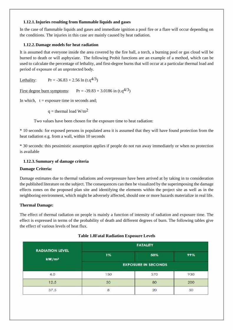
The effect of thermal radiation on people is mainly a function of intensity of radiation and exposure time. The effect is expressed in terms of the probability of death and different degrees of burn. The following tables give the effect of various levels of heat flux.
Table 1.8Fatal Radiation Exposure Levels

Table 1.9 Detils of damage due to radiation
Table 1.10Overpressure Damage
1.13. Result of maximum credible accident analysis (Mca)
The maximum credible accident scenarios for the M/s Shalini Organics have been identified and listed in Table 11. Following is the accident potential and the likely damage for the identified accident scenarios.

Table 1.11 Damage Distances Due to Spilled/Pool Product Fire Scenario, Jet Fire, BLEAVE Fireball of tank Rupture/failure, Leak from hole in tank
Methanol Storage Tank Heat Radiation Intensity
(Kw/m2) Jet Fire Pool Fire Tank on fire
37.5 Kw/m2 for first Isopleth 7.95 M 33.06 M 2.02 25 Kw/m2 for Second Isopleth 9.89 M 40.56 M 2.02 12.5 Kw/m2 for Third Isopleth 13.74 M 57.67 M 2.52
4 Kw/m2 for fourth Isopleth 24.98 M 102.86 M 5.02 Toluene Storage Tank
Heat Radiation Intensity (Kw/m2) Jet Fire Pool Fire Tank on fire
37.5 Kw/m2 for first Isopleth 7.00 42.42 2.01 25 Kw/m2 for Second Isopleth 9.01 52.45 2.5 12.5 Kw/m2 for Third Isopleth 12.50 73.56 3.52
4 Kw/m2 for fourth Isopleth 22.65 130.73 6.71 Acetone Storage Tank
Heat Radiation Intensity (Kw/m2) Jet Fire Pool Fire Tank on fire
37.5 Kw/m2 for first Isopleth 14.19 1.92 2.01 25 Kw/m2 for Second Isopleth 17.69 2.92 3.21 12.5 Kw/m2 for Third Isopleth 25.19 5.42 6.51
4 Kw/m2 for fourth Isopleth 45.19 8.92 10.51 Ethyl Acetate Storage Tank
Heat Radiation Intensity (Kw/m2)
Jet Fire Pool Fire Tank on fire
37.5 Kw/m2 for first Isopleth 15.62 37.95 1.90 25 Kw/m2 for Second Isopleth 19.12 46.95 2.90 12.5 Kw/m2 for Third Isopleth 26.62 66.45 5.40
4 Kw/m2 for fourth Isopleth 47.62 117.45 8.90 Denatured Sprit Storage Tank
Heat Radiation Intensity (Kw/m2) Jet Fire Pool Fire Tank on fire
37.5 Kw/m2 for first Isopleth 13.67 19.79 2.01 25 Kw/m2 for Second Isopleth 16.78 24.29 -- 12.5 Kw/m2 for Third Isopleth 23.69 34,29 --
4 Kw/m2 for fourth Isopleth 41.76 60.36 3.01 Triethyl Amine HSD Drum
Heat Radiation Intensity (Kw/m2) Pool Fire BLEVE Pool Fire
37.5 Kw/m2 for first Isopleth 1.55 48.18 4.56 25 Kw/m2 for Second Isopleth -- 64.18 5.56 12.5 Kw/m2 for Third Isopleth 2.54 80.01 7.56
4 Kw/m2 for fourth Isopleth 4.04 98.18 13.56
Conclusion:
Based on the unsafe distances identified by the software output file, the MCLS (maximum credible loss scenario) for the factory works out to about 130.74 meter considering pool fire scenario for Toluene with 4.0 kW/ (Sq. m) impact in the environment.
The scenario considered for assessing the impact by quantitative risk assessment was taken from standard guideline.
The probability of occurrence of the scenario is very less. The Disaster management plan highlights the suggestive measures to be taken during the occurrence of such an accident.
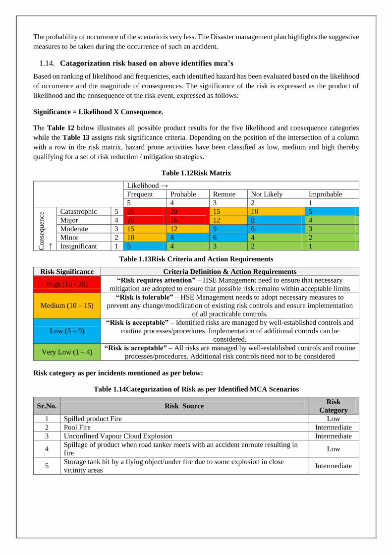
1.14. Catagorization risk based on above identifies mca’s
Based on ranking of likelihood and frequencies, each identified hazard has been evaluated based on the likelihood of occurrence and the magnitude of consequences. The significance of the risk is expressed as the product of likelihood and the consequence of the risk event, expressed as follows:
Significance = Likelihood X Consequence.
The Table 12 below illustrates all possible product results for the five likelihood and consequence categories while the Table 13 assigns risk significance criteria. Depending on the position of the intersection of a column with a row in the risk matrix, hazard prone activities have been classified as low, medium and high thereby qualifying for a set of risk reduction / mitigation strategies.
Table 1.12Risk Matrix
Likelihood → Frequent Probable Remote Not Likely Improbable 5 4 3 2 1
Con
sequ
ence
→
Catastrophic 5 25 20 15 10 5 Major 4 20 16 12 8 4 Moderate 3 15 12 9 6 3 Minor 2 10 8 6 4 2 Insignificant 1 5 4 3 2 1
Table 1.13Risk Criteria and Action Requirements
Risk Significance Criteria Definition & Action Requirements
High (16 - 25) “Risk requires attention” – HSE Management need to ensure that necessary
mitigation are adopted to ensure that possible risk remains within acceptable limits
Medium (10 – 15) “Risk is tolerable” – HSE Management needs to adopt necessary measures to
prevent any change/modification of existing risk controls and ensure implementation of all practicable controls.
Low (5 – 9) “Risk is acceptable” – Identified risks are managed by well-established controls and
routine processes/procedures. Implementation of additional controls can be considered.
Very Low (1 – 4) “Risk is acceptable” – All risks are managed by well-established controls and routine
processes/procedures. Additional risk controls need not to be considered
Risk category as per incidents mentioned as per below:
Table 1.14Categorization of Risk as per Identified MCA Scenarios
Sr.No. Risk Source Risk Category
1 Spilled product Fire Low 2 Pool Fire Intermediate 3 Unconfined Vapour Cloud Explosion Intermediate
4 Spillage of product when road tanker meets with an accident enroute resulting in fire
Low
5 Storage tank hit by a flying object/under fire due to some explosion in close vicinity areas
Intermediate
1.15. Analysis for propensity towards predicted consequences
Risk of operation of any activity involving hazardous chemicals consists of the following two elements:
Consequences of certain unwanted event & Propensity that these consequences will occur.
Propensity or likelihood of the predicted consequence for the Installation will depend upon the following items:
Propensity of the Installation towards occurrence of initiating event. Propensity that the designed counter measures provided in the Installation would fail. Propensity of certain consequence of an accident.
1.15.1. Possibility of fire & it’S propagation
Primarily there could be fire (ignition of spilled or leaked Product), flare (jet fire) or pool fire in the Installation. Pool fire is possible at the tank farm only whereas fire and flare are possible at any pipeline containing Chemicals, Storage yard, Pump and Road Tank Truck.
1.15.2. Spilled Product fire
The Product may get spilled and come in contact with a potential ignition source. In this case, it will catch fire. Extent of fire will depend on quantity of Chemicals (Toluene, Acetone, Methanol, Ethyl Acetate, Denatural Spirit, Triethyl Amine) released and profile of the surface on which it has been spilled. Such fire may also cause fire in the nearby flammable/combustible material, if any. This type of fire must be extinguished immediately and propagation of fire should be stopped.
1.15.3. Jet fire in Pipeline/product pump house/tank farm/tt decanting area/tank truck
If there is a leakage in the pipeline and there is availability of any ignition source, jet fire may occur. In such cases the leaked product may travel up to the ignition source and the fire may travel back to the place of leakage or the leaked Product may catch fire at the place of leakage itself. Considering the worst possible case, such a jet fire may cause direct damage up to 10 to 35 m for a leak size of 2 to 5 cm diameter and Product being released with the head of 5 to 10 m. The flame impingement and may cause further damage.
In this case also there would be sufficient time available for the persons to come out from the affected area, if any. In such cases isolating the affected pipeline should be given first priority than extinguishing the fire. The affected equipment (being heated by the heat) should be kept cool with flow of water from monitor/hydrant.
1.15.4. Propensity of the Installation towards occurance of such initiating event
The event could be a single component failure, for example, leakage of product from pipeline or any equipment or any tank. To evaluate this aspect for the Plant, Hazard and Operability Studies (HAZOP) has to be carried out.
1.15.5. Propensity of failure of the designed counter measures
Upon occurrence of the initiating event, certain designed counter measures in the Installation would start functioning for example isolation of the affected area from other areas by the personnel by closing the valves to restrict the quantity of escaping chemicals; on hearing the emergency alarm the emergency team would immediately start functioning and take the necessary action to restrict or limit the damage. On the contrary these counter measures may fail also. Therefore, a lot would depend on response of the emergency team. Hazards & Operability Studies, (HAZOP) needs to be carried out to evaluate this aspect in detail.
1.15.6. Propoensity of a certain consequence of an accident
Any initiating event would take place first, there after the designed counter measures would attempt to limit the effects of the initiating event. Such deviations from the intended operation may lead to an accident. In reality, accident scenario and severity of the consequences will depend on type of product leaked, quantity of the product

leaked, location of the incident (tank farm/pumps/T/T plate form), availability of ignition source, response of emergency systems and emergency team, weather conditions (wind velocity & direction), etc. Further propensity of being killed or injured would also depend on the aspects like time of accident and number of people in damage area at that time.
1.15.7. Probability estimation for occurance of mca scenario
Applying equipment failure rate data and ignition probability data probability values have been estimated for consequences of various MCA scenarios, which are as follows:
For the following accident scenarios the categorization is as follows, which is inferred on the basis of past accident analysis, information & approach provided in Green Book & Purple Book of EFFECTS, TNO:
Table 1.15Probability of Occurrences of Identified MCA Scenarios
Sr.No. Categorization Probability Range 1 Low < 10-3 To< or = 10-4 per year 2 Very Low < 10-4 To< or = 10-6 per year 3 Extremely Low < 10-6 per year on wards
Table 1.16The probabilities for various accident scenarios have been estimated
Sr.No. Accident Scenario Probability 1 Spilled Product catching fire Very Low (about 10-5 per year)
2 Jet Fire in Pipeline/Product Pumps/Tank Farm /TT Decanting Area/Tank Truck
Very Low (about 10-5 per year)
3 Pool Fire in solvents in Main Tank farm Very Low (about 10-6 per year)
4 Vapor Cloud Explosion due to major release of Class A product from storage unit
Extremely Low (about 10-8 per year)
1.16. Uncertainty surrounding consequence analysis
Analytical and mathematical models employed in quantification of damage distances are based on many considerations, which have been discussed earlier.
In many cases, very general data is available on component and equipment failures, for which statistical accuracy is often poor. Probability data has been found quite subjective, so that, when combined in a fault tree or event tree the incident frequencies thus computed may not have a higher confidence range. Furthermore, it is difficult
to infer the comparison between frequencies of two catastrophic events, for example propensity of 10-4 and 10-5 per annum.
1.17. Alarp principle
ALARP stands for "as low as reasonably practicable". The ALARP principle is that the residual risk shall be as low as reasonably practicable. It has particular connotation as a route to reduce risks SFAIRP (so far as is reasonably practicable) in UK Health and Safety law. For a risk to be ALARP it must be possible to demonstrate that the cost involved in reducing the risk further would be grossly disproportionate to the benefit gained. The ALARP principle arises from the fact that infinite time, effort and money could be spent on the attempt of reducing a risk to zero. It should not be understood as simply a quantitative measure of benefit against detriment. It is more a best common practice of judgment of the balance of risk and societal benefit. Following figure shows ALARP diagram.

NOTE- A risk of 10 per million per year or 10-5/Year; effectively means that any person standing at a point of this level of risk would have a 1 in 100 000 chance of being fatally injured per year.
From table No. 15, it can be seen that, the probability / frequency of occurrence of Pool Fire due to catastrophic failure of Storage tank structure is 1 x 10⁻⁶, and VCE is 1 x 10⁻⁸ per Year. Hence, as per ALARP Principle, the risk is coming under “Broadly Acceptable region” which require maintaining normal precautions within the
Installation area.
Risk Assessment Criteria: In order to determine acceptability, the risk results are assessed against a set of risk criteria as per UK HSE criteria.
UK HSE criteria: Following points detail the UK HSE guidelines:
An individual risk below 1 x 10⁻⁶ fatalities per year is considered as acceptable for both plant workers and public. An individual risk above 1 x 10⁻⁴ fatalities per year for public is considered as unacceptable and an individual risk above 1 x 10⁻³ fatalities per year for workers is considered unacceptable. Between these limits the risk is considered as ALARP (As Low as Reasonably Practicable). An indication of this is shown in the below figure
Societal risk can be represented by FN curves, which are plots of the cumulative frequency (F) of various accident scenarios against the number (N) of casualties associated with the modelled incidents. The plot is cumulative in the sense that, for each frequency, N is the number of casualties that could be equaled or exceeded.
Often ‘casualties’ are defined in a risk assessment as fatal injuries, in which case N is the number of people that
could be killed by the incidents.
IRPA
10-3/yr
10-4/yr
10-5/yr
10-6/yr
Intolerable
The ALARP or Tolerableregion (Risk is tolerated only)
Broadly Acceptable region(no need for detailed working todemonstrate ALARP)
Fundamental improvements needed.Only to be considered if there are no
alternatives and people are well informed
Too high, significant effort required toimprove
High, investigate alternatives
Low, consider cost-effective alternatives
Negligible, maintain normal precautions

Individual Risk Criteria
The UK HSE Individual Risk Criteria was considered to assess the risk for Plant. Individual risk above 10-3 per annum for any person shall be considered intolerable and fundamental risk reduction improvements are required.
Risk criteria for Individual Risk for on-site are as follows:
Individual risk levels above 1 x 10⁻³ per year will be considered unacceptable and will be reduced, irrespective of cost
Individual risk levels below 1 x 10⁻⁶ per year will be broadly acceptable
Risk levels between 1 x 10⁻³ and 1 x 10⁻⁶ per year will be reduced to levels as low as reasonably practicable (ALARP). That is the risk within this region is tolerable only of further risk reduction is considered impracticable because the cost required to reduce the risk is grossly disproportionate to the improved gained
Societal Risk Criteria When considering the risk associated with a major hazard facility, the risk to an individual is not always an adequate measure of total risks; the number of the individuals at risk is also important. Catastrophic incidents with the potential multiple fatalities have a little influence on the level of risk but have a disproportionate effect on the response of society and impact of company reputation.
The concept of societal risk is much more than that for individual risk. A number of factors are involved which make it difficult to determine single value criteria for application to a number of different situations. These factors include;
- The hazard, the consequential risks and the consequential benefits
- The nature of assessment
- Factors of importance to the company, government, regulators and authorities, public attitudes and perception and aversion to major accident
Societal risk is the relationship between frequency of an event and the number of people affected. Societal risk from a major hazard facility can thus be expressed as the relationship between the number of potential fatalities

N following a major accident and frequency F at which N fatalities are predicated to occur. The relationship between F and N, and the corresponding relationship involving F, the cumulative frequency of events causing N or more fatalities, are usually presented graphically on log-log axis.
Societal risk should not be confused as being the risk to society or the risk as being perceived by society. The word “societal” is merely used to indicate a group of people and societal risk refers to the frequency of multiple fatality incidents, which includes workers and the public. Societal risk is usually represented by an FN (Frequency – Number of Fatality) curve.
Figure 1.2 FN Curve
The highest frequency is found to be 1E-05/ year associated to Three (3) fatalities and the maximum number of fatalities is Thirteen (13) with frequency of 4E-06/ year. F-N results, concludes that the Societal Risk falls in the ALARP region.
Conclusion for IR/SR
1 Individual Risk (IR) The IR value throughout the plant estimated is 4.5E-05 per year, which is in ALARP region.
2 Expected Number of Fatalities (PLL) The estimated overall Potential Loss of Life (PLL) for the plant population is estimated 7E-05 per year.
3 Societal Risk (F-N Curve) The F-N curves show that societal risk for the overall population considered mostly falls in the ALARP region (10-4 to 10-5).
NOTE - A risk of 10 per million per year, or 10-5/Year, effectively means that any person standing at a point of this level of risk would have a 1 in 100 000 chance of being fatally injured per year.
1.17.1. Mitigation/preventive measures for mca scenarios
In order to mitigate/prevent any minor incident from becoming a major accident following measures along with Onsite and if required Offsite Emergency (Disaster) Management Plan should be followed:
Spillage in tank area: small leakage through tank valves/joints will take a form of spillage if not identified immediately. If this spillage gets on contact with ignition source will take a form of fire and lead to an accident.
In order to prevent it from becoming a major accident, stop the operation immediately. Remove the spillage with proper corrective method from that area. REMOVE SPILLED PRODUCT using Sand or Fire Extinguishers (By Spreading Foam Solution). Do not touch or walk through spilled material, stop leak if possible. Use water spray to reduce vapor, do not put water directly on leak or spill area. And if ignition of spilled product takes place necessary emergency procedure must be followed as soon as possible to avoid damage to other property due to secondary effect accidents. For small spillage, flush area with flooding amounts of water. Pool Fire in tank farm Area: Failure of outlet valve of tanks or any one of valve will lead to leakage of product. This will form a pool inside tank farm area if not identified immediately. This pool if comes in contact with an ignition source will lead to a major accident. In order to mitigate it, stop the operation immediately. Be ready will all firefighting equipments at the site. Start sprinkler system to cool the surrounding tanks. Immediately follow both onsite and offsite emergency plan. Tank on Fire: For preventing tank on fire, cool the surrounding tanks by means of sprinkler system and foam system. Bring all firefighting equipments at the site and start fighting with fire following proper onsite emergency plan. Unconfined Vapor Cloud Explosion: UVCE is a secondary domino effect. Vapors releasing into atmosphere are not in so much quantity that it lead to an explosion. For an ignition, a proper mixture of fuel to air is required, if this mixture between UEL & LEL comes in contact with an ignition source, it will lead to an explosion. In order to prevent it, immediately stop the leakage from the source by identifying it. For this, it is recommended to install hydrocarbon Detector in Pump House area, Tank Farm area and TT Gantry area (we have separately recommended this point in recommendation heading 4.

Page 27
Figure 1.3 Pool Fire Scenario for Methanol Tanks Enclosed in Tank farm area showing Damage Distances for considered Heat Intensities

Figure 1.4 Jet Fire Scenario for Methanol Tanks Enclosed in Tank farm area showing Damage Distances for considered Heat Intensities

Figure 1.5 Pool Fire Scenario for Toluene Tanks Enclosed in Tank farm area showing Damage Distances for considered Heat Intensities

Figure 1.6 Pool Fire Scenario for Acetone Tanks Enclosed in Tank farm Area showing Damage Distances for considered Heat Intensities

Figure 1.7 Jet Fire Scenario for Acetone Tanks Enclosed in Tank farm area showing Damage Distances for considered Heat Intensities

Figure 1.8 : Pool Fire Scenario for Ethyl Acetate Tanks Enclosed in Tank farm Area showing Damage Distances for considered Heat Intensities

Figure 1.9 Jet Fire Scenario for Ethyl Acetate Tanks Enclosed in Tank farm area showing Damage Distances for considered Heat Intensities

Figure 1.10 Pool Fire Scenario for Denatured Sprit Tanks Enclosed in Tank farm Area showing Damage Distances for considered Heat Intensities

Figure 1.11 Damage Distances Due to BLEVE Fire ball in Triethyl Amine

1.17.2. Recommendations
The periodic inspection and maintenance program on the tank would be ensured. The periodic maintenance of the pumps and piping would be ensured. Least number of flanged joints will be provided in the pipelines. The pipelines will be supported adequately so as to avoid sagging of the same during operation. Visual inspection of the pipelines will be done periodically to ascertain external pitting and
corrosion. Protective painting on the tank and pipeline shall be provided. Protective equipment such as gloves, lab coat, vapor respirator, splash goggles shall be ensured
while handling the substance. Prominent signage of hazards (such as “Danger”, No smoking”) of the substances shall be provided
on the tank and surroundings The tank installation will be protected against lightening. All Electric Equipment & Fittings (e.g. Pump-motors, lamps, junction boxes, switches etc.) shall
be of Flame-proof Type, conforming to IS/IEC 60079 i.e. old IS 2148:1981, suitable for GR. II A/II B and shall be of type approved by the CCoE.
Earthing is to be provided to the storage area for dealing with the static charges that might generate during the loading and unloading of the solvents.
Provision of sand buckets, foam monitor, fire extinguishers & hydrant line near PESO area were made available.
Appropriate drainage with the slope of 2 % is provided to remove small and large spillage of the chemicals.
Provision of spill kit is provided to deal with the minor spillage scenario. Permission of Joint Chief Controller (explosives), West circle is obtained Solvent storage is constructed of non combustible materials. The secondary containment is provided and is kept clean and free from any accumulation of
inflammable liquids. The storage shed is ventilated near the ground level and also near the roof. The ventilators are
covered with two layers of fine copper or non corrodible metal wire gauge of mesh not less than 11 meshes per linear cm.
No alteration is carried out without written permission of licensed authority. The safety distance of 7.5mtr is kept from the shed. All the empty receptacles are kept securely closed unless they have been thoroughly cleaned. The suitable extinguishers (DCP) are kept immediately outside the storage shed. Daily inventory of Solvent is to be maintained. The chemicals are isolated from another chemical in well ventilated area and hazard warning
information is shown. SOP is prepared for handling such chemicals and it should be strictly followed. Spill kit is provided for storage to limit the spill of materials. Suitable Absorbent like sodium bi
carbonate is used to absorb the spill. Proper training is provided to workers prior to handling and transporting chemicals. PPE’s like face shield, goggles, apron, gloves, gumboots are used while handling the chemicals to
avoid exposure to chemicals. The raw materials are stored according to their compatibility.

Toxic materials are stored in cool place and kept away from heat. Toxic material can cause breathing difficulty therefore storage area is well ventilated. Good housekeeping practice is implemented in storage area. Appropriate drainage with the slope of 2 % is provided to remove small and large spillage of the
chemicals. The provision of fire water supply is provided through the hydrant line passing from the raw
material storage area PPE’s are used wherever necessary. MSDS recommendations are strictly followed while chemical storage and handling