1 A STEM BASED MODEL ROCKETRY CURRICULUM: FOR THE …
166
Transcript of 1 A STEM BASED MODEL ROCKETRY CURRICULUM: FOR THE …


1
A STEM BASED MODEL ROCKETRY CURRICULUM: FOR THE TEAM AMERICA ROCKETRY CHALLENGE
Thomas M. Sarradet, Jr. B.F.A., University of Louisiana, Lafayette, 1980
PROJECT
Submitted in partial satisfaction of the requirements for the degree of
MASTER OF ARTS
in
EDUCATION (Educational Leadership & Policy Studies)
at
CALIFORNIA STATE UNIVERSITY, SACRAMENTO
FALL 2009

2
TABLE OF CONTENTS
CHAPTER 1 INTRODUCTION ................................................................................. 6
Description ........................................................................................................................ 7
Setting ............................................................................................................................... 7
Limitations of Model Rocketry ......................................................................................... 7
CHAPTER 2 SKILLS AND STANDARDS .............................................................. 8
Introduction ....................................................................................................................... 8
Skills Set ............................................................................................................................ 8
List of Lessons ................................................................................................................ 10
STEM Standards ............................................................................................................. 11
CHAPTER 3 LESSONS ........................................................................................... 23
Lecture and Demonstration .......................................................................................... 23
LD01: Introduction to Rocketry ...................................................................................... 24
LD02: The Model Rocket ................................................................................................ 25
LD03: Newton‟s Laws of Motion ................................................................................... 26
LD04: Aerodynamics ...................................................................................................... 27
LD05: Rocket Stability .................................................................................................... 28
LD06: Launch Procedures ............................................................................................... 29
LD07: TARC Rules ......................................................................................................... 30
LD08: Model Rocketry Rules ......................................................................................... 31
Notes to Lecture & Demonstration Lessons .................................................................... 32
LD01: Introduction to Model Rocketry ........................................................................... 32
LD02: The Model Rocket ................................................................................................ 34
LD03: Newton‟s Laws of Motion ................................................................................... 42
LD04: Aerodynamics ...................................................................................................... 44
LD05: Rocket Stability .................................................................................................... 47
Design and Engineering ................................................................................................ 50
DE01: Introduction to Rocksim....................................................................................... 51

3
DE02: The Booster Section ............................................................................................. 52
DE03: The Payload Section ............................................................................................ 53
DE04: Painting and Finishing ......................................................................................... 54
DE05: Rocket Engines .................................................................................................... 55
DE06: Recovery Systems ................................................................................................ 56
DE07: Model Rocket Launch Equipment ....................................................................... 57
Construction .................................................................................................................. 58
C01: Model Rocket Parts Inventory ................................................................................ 59
C02: Model Rocket Construction: The Motor Mount ..................................................... 60
C03: Model Rocket Construction: Fins, Airframe, Nose ................................................ 61
C04: Model Rocket Construction: Payload Bays ............................................................ 62
C05: Model Rocket Construction: Finishing ................................................................... 63
C06: Recovery Systems ................................................................................................... 64
Investigation and Discovery ......................................................................................... 65
ID01: Data Collecting Instruments .................................................................................. 66
ID02: Investigating Parachutes........................................................................................ 67
ID03: Calculating Apogee ............................................................................................... 68
ID04: Adjusting Apogee ................................................................................................. 70
ID05: Adjusting Descent Rate Using Parachutes & Streamers ....................................... 71
ID06: Investigating Average Velocity ............................................................................. 72
ID07: Investigating Energy ............................................................................................. 73
ID08: Investigating Nose Drag Co efficiency ................................................................. 74
ID09: Investigating Streamers ......................................................................................... 75
ID10: Investigating Weathercocking ............................................................................... 76
ID11: Entering and Analyzing Flight Data in Rocksim .................................................. 77
ID12: Determining the Center of Pressure ...................................................................... 78
D13: Determine the Center of Gravity and Stability of a Rocket .................................... 79
ID14: Basic Meteorology ................................................................................................ 80

4
CHAPTER 4 TRAINING, ORGANIZATION, AND EQUIPMENT .................... 81
Description of Positions .................................................................................................. 84
Assignment Recommendations ....................................................................................... 89
Duty Rotation .................................................................................................................. 90
Training ........................................................................................................................... 90
Launch Site ...................................................................................................................... 91
Equipment ....................................................................................................................... 91
Design and Engineering Equipment ................................................................................ 91
Construction Equipment and Material ............................................................................. 92
Launch Equipment .......................................................................................................... 92
Data Collection Equipment ............................................................................................. 94
APPENDIX 1: COUNTDOWN PROCEDURES ....................................................... 96
APPENDIX 2: ENGINEER CHECKLIST ................................................................. 98
APPENDIX 3: FLIGHT LOG ...................................................................................... 99
APPENDIX 4: METEOROLOGIST WORKSHEET .............................................. 100
APPENDIX 5: RECOMMENDED REFERENCE LIBRARY ............................... 101
REFERENCES ............................................................................................................ 102

5
Questions or comments may be sent to
Tom Sarradet E.V. Cain Middle School
150 Palm Ave. Auburn, CA 95603
Email: [email protected]

6
CHAPTER 1 INTRODUCTION
Since the publication of A Nation at Risk in 1981, there has been a steady progression toward standards based education. The researcher found common language in many of the standards publications. The authors of those documents saw a need for integrated curricula that taught several disciplines, such as math and science, in one curriculum. They saw a benefit not only in time management but also in a better understanding of the content by the students. The authors also saw the advantages of more hands-on activities instead of classroom lectures. Math and science is about using those disciplines to make things and to solve problems. It is not about taking tests and hearing lectures.
There is a strong need for the educational community to embrace these concepts and move out of the classrooms into the field for a real-world learning experiences. The popularity of national competitions may be offered as proof that students are just as willing to embrace an interactive approach to learning.
Model rocketry is a powerful tool for teachers who wish to incorporate science, technology, engineering, and math into a fun, engaging, and challenging activity. When designing model rockets in the computer lab, the students have an opportunity to match their ingenuity with the limits of Newton‟s Laws of Physics in order to design their own model rocket that is aerodynamically sound. Fine motor skills are honed during the construction of the rockets as they measure, cut, and glue their rocket parts to the specifications that they themselves determined. Teamwork is a skill that they acquire and they organize into a group with many specialized responsibilities for the purpose of launching their rockets and collecting valuable data to be processed and analyzed in the classroom. Suddenly, the Pythagorean Theorem makes sense as they visualize the giant triangle formed by the flight path of their rocket. Newton‟s Laws are in full enforcement right before their very eyes. Through the activities of model rocketry, science and math not only exist, they “come to life.”

7
Description The primary purpose of this curriculum is to teach the STEM skills necessary for
middle and high school students to successfully compete in the Team America Rocketry Challenge.
Setting
The curriculum may also be used, in whole or in part as: a training program for TARC member. an elective class in middle and high school.
an extracurricular course. A model rocket club curriculum. a hands-on activity for a middle or high school science or math class. a summer camp program.
Limitations of Model Rocketry
Launching model rockets require access to a launch area that meets the size requirements in accordance with the Model Rocket Safety Code. Schools typically have athletic fields that meet Type A and B model rocket motor requirements of 122 square meters. The Educator may also contact their local National Association of Rocketry club for access to the club‟s launch sites. NAR clubs support local rocketry education efforts and will usually welcome students on their launch sites with proper notification and preparation. Educators may find club information on the NAR website (National Association of Rocketry, 2009). The local fire laws should be investigated prior to the use of solid propellants. If laws do prohibit them, the curriculum may be altered to use water or air as a means of propulsion. Water rockets can be set up to deploy a recovery system and to carry payloads and electronic altimeters. Educators who use this curriculum for training a TARC team should conduct the training prior to the teams beginning their design and build. Once the students begin the contest, educators and mentors are prohibited from aiding in the design and construction of a TARC rocket.
8
CHAPTER 2 SKILLS AND STANDARDS Introduction
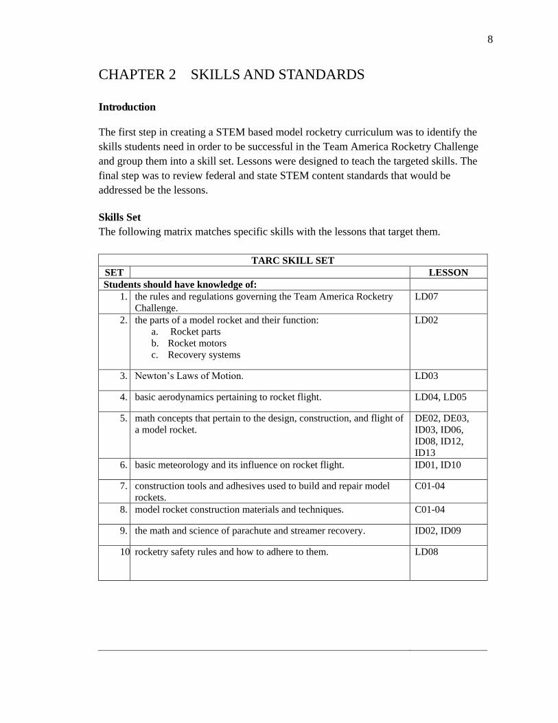
The first step in creating a STEM based model rocketry curriculum was to identify the skills students need in order to be successful in the Team America Rocketry Challenge and group them into a skill set. Lessons were designed to teach the targeted skills. The final step was to review federal and state STEM content standards that would be addressed be the lessons. Skills Set The following matrix matches specific skills with the lessons that target them.
TARC SKILL SET SET LESSON Students should have knowledge of:
1. the rules and regulations governing the Team America Rocketry Challenge.
LD07
2. the parts of a model rocket and their function: a. Rocket parts b. Rocket motors c. Recovery systems
LD02
3. Newton‟s Laws of Motion. LD03
4. basic aerodynamics pertaining to rocket flight. LD04, LD05
5. math concepts that pertain to the design, construction, and flight of a model rocket.
DE02, DE03, ID03, ID06, ID08, ID12, ID13
6. basic meteorology and its influence on rocket flight. ID01, ID10
7. construction tools and adhesives used to build and repair model rockets.
C01-04
8. model rocket construction materials and techniques. C01-04
9. the math and science of parachute and streamer recovery. ID02, ID09
10.rocketry safety rules and how to adhere to them. LD08
9
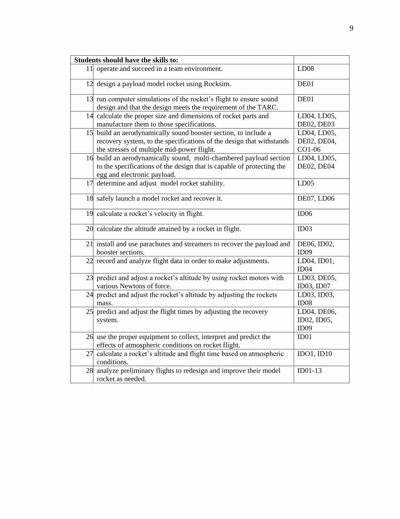
Students should have the skills to:
11.operate and succeed in a team environment. LD08
12.design a payload model rocket using Rocksim. DE01
13.run computer simulations of the rocket‟s flight to ensure sound design and that the design meets the requirement of the TARC.
DE01
14.calculate the proper size and dimensions of rocket parts and manufacture them to those specifications.
LD04, LD05, DE02, DE03
15.build an aerodynamically sound booster section, to include a recovery system, to the specifications of the design that withstands the stresses of multiple mid-power flight.
LD04, LD05, DE02, DE04, CO1-06
16.build an aerodynamically sound, multi-chambered payload section to the specifications of the design that is capable of protecting the egg and electronic payload.
LD04, LD05, DE02, DE04
17.determine and adjust model rocket stability. LD05
18.safely launch a model rocket and recover it. DE07, LD06
19.calculate a rocket‟s velocity in flight. ID06
20.calculate the altitude attained by a rocket in flight. ID03
21. install and use parachutes and streamers to recover the payload and booster sections.
DE06, ID02, ID09
22.record and analyze flight data in order to make adjustments. LD04, ID01, ID04
23.predict and adjust a rocket‟s altitude by using rocket motors with various Newtons of force.
LD03, DE05, ID03, ID07
24.predict and adjust the rocket‟s altitude by adjusting the rockets mass.
LD03, ID03, ID08
25.predict and adjust the flight times by adjusting the recovery system.
LD04, DE06, ID02, ID05, ID09
26.use the proper equipment to collect, interpret and predict the effects of atmospheric conditions on rocket flight.
ID01
27.calculate a rocket‟s altitude and flight time based on atmospheric conditions.
IDO1, ID10
28.analyze preliminary flights to redesign and improve their model rocket as needed.
ID01-13

10
List of Lessons
Lecture & Demonstration LD01 Introduction to Rocketry LD02 The Model Rocket LD03 Newton‟s Laws of Motion LD04 Aeronautics LD05 Rocket Stability LD06 Launch Procedures LD07 TARC Rules LD08 Model Rocketry Rules Design & Engineering DE01 Rocksim DE02 The Booster Section DE03 The Payload Section DE04 Painting and Finishing DE05 Rocket Engines DE06 Recovery Systems DE07 Launching a Model Rocket Construction C01 Model Rocket Building Preparation C02 Motor Mount C03 Fins, Airframe, Nose C04 Payload Bays C05 Finishing C06 Recovery Systems Investigation & Discovery ID01 Data Collecting Instruments ID02 Investigating Parachutes ID03 Calculating Apogee ID04 Adjusting Apogee ID05 Adjusting Descent Rate Using Parachutes & Streamers ID06 Investigating Average Velocity ID07 Investigating Energy ID08 Investigating Nose Cone Drag Co efficiency ID09 Investigating Streamers ID10 Investigating Weathercocking ID11 Adding and Analyzing Data in Rocksim ID12 Determining Center of Pressure ID13 Determining Center of Gravity ID14 Basic Meteorology

11
STEM Standards
Listed are national and state standards that the researcher has identified as standards that may be taught through the use of this curriculum. Each listed standard is matched with the TARC skills and the lessons that apply to it. Some standards are addressed by most of the lessons, but for the sake of clarity the researcher chose to identify a select few as examples. Standards that the researcher determined do not directly apply to model rocketry have been omitted; therefore this is not a complete list of the standards. The model rocketry curriculum is not intended to replace science or math courses, but rather to enhance and reinforce them.
NATIONAL AND CALIFORNIA STEM STANDARDS: SCIENCE National Science Education Standards Skill Lesson Content Standards: 5-8
As a result of activities in grades 5-8, all students should develop A Abilities necessary to do scientific inquiry Understand about scientific inquiry
11- 28
All
B an understanding of Motions and forces Transfer of energy
3 4 17 23
LD03 LD04 LD05 DE05 ID03 ID07
E Abilities of technological design Understandings about science and technology All All
G an understanding of Science as a human endeavor Nature of science History of science
All All
Content Standards: 9 - 12 As a result of activities in grades 9 - 12, all students should develop
A Abilities necessary to do scientific inquiry Understandings about scientific inquiry 19 20 22- 28
ID06 ID03 ID07 ID08
B an understanding of Motions and forces 3 4 5 17 23 24 25 27
LD03 LD04 LD05 DE05 ID03 ID07
E Abilities of technological design Understanding about science and technology 12 13 15 16
DE01 LD04 LD05 DE02 DE04
C01-06

12
G develop an understanding of Science as a human endeavor Nature of scientific knowledge Historical perspectives
All All
Program Standards B
The program of study in science for all students should be developmentally appropriate, interesting, and relevant to students‟ lives; emphasize student understanding through inquiry; and be connected with other school subjects.
All All
C The science program should be coordinated with the mathematics program to enhance student use and understanding of mathematics in the study of science and to improve student understanding of mathematics.
All All
California State Standards for Grade 8 SCIENCE (Physical Science) Standard Set 1. Motion 1. The velocity of an object is the rate of change or its position. a. position is defined relative to some choice of standard reference point and a
set of reference directions. 4 LD04
b. average speed is the total distance traveled divided by the total time elapsed. 19 ID06 c. The speed of an object along the path traveled can vary. d. how to solve problems involving distance, time, and average speed. 19 ID06 e. to describe the velocity of an object one must specify both direction and
speed. 4 LD04
f. changes in velocity can be changes in speed, direction, or both. 4 LD05 g. how to interpret graphs of position versus time and speed versus time for
motion in a single direction. 4 LD04
Standard Set 2. Forces 2. Unbalanced forces cause changes in velocity. Students know a. a force has both direction and magnitude. 3
4 LD02 LD03
b. when an object is subject to two or more forces at once, the effect is the cumulative effect of all the forces.
4 LD04
c. when the forces on an object are balanced, the motion of the object does not change.
3 17
LD03 LD05
d. how to identify separately two or more forces acting on a single static object, including gravity, elastic forces due to tension or compression in matter, and friction.
3 LD03
e. when the forces on an object are unbalanced the object will change its motion (that is, it will speed up, slow down, or change direction).
3, 4,
17
LD03 LD04 LD05
f.
the greater the mass of an object the more force is needed to achieve the same change in motion.
3 23 24
LD03 DE05 ID03 ID07 ID08
Standard Set 9. Investigation and Experimentation 9. As a basis for understanding this concept, and to address the content the other three strands,
students should develop their own questions and perform investigations. Students will: a. plan and conduct a scientific investigation to test a hypothesis. All All

13
b. evaluate the accuracy and reproducibility of data. 23
24 25 26
LD03 LD04 DE05 DE06 ID02 ID03 ID05 ID07 ID08 ID09
c. distinguish between variable and controlled parameters in a test. 23 24 25 26
LD03 LD04 DE05 DE06 ID02 ID03 ID05 ID07 ID08 ID09
d. recognize the slope of the linear graph as the constant in the relationship y=kx and apply this to interpret graphs constructed from data.
2 LD07
e. construct appropriate graphs from data and develop quantitative statements about the relationships between variables.
26 ID01
f. apply simple mathematical relationships to determine one quantity given the other two (including speed = distance/time, density = mass/volume, force = pressure x area, volume=area x height).
20 ID03
High School Physics Motion and Forces 1. Newton‟s laws predict the motion of most objects. As a basis for
understanding this concept: 3 LD03
a. Students know how to solve problems that involve constant speed and average speed.
19 ID06
b. Students know that when forces are balanced, no acceleration occurs; thus an object continues to move at a constant speed or stays at rest (Newton‟s first law).
18 DE07 LD06
c. Students know how to apply the law F = MA to solve one-dimensional motion problems that involve constant forces (Newton‟s second law).
3 19 26
LD03 ID01 ID06
d. Students know that when one object exerts a force on a second object, the second object always exerts a force of equal magnitude and in the opposite direction (Newton‟s third law).
3 4
LD03 LD04 LD05
e. Students know the relationship between the universal law of gravitation and the effect of gravity on an object at the surface of Earth.
4 20 21
LD04 LD05 ID03 DEO
6 ID02 ID09
f.
Students know applying a force to an object perpendicular to the direction of its motion causes the object to change direction but not speed (e.g., Earth‟s gravitational force causes a satellite in a circular orbit to change direction but not speed).
4 ID10
14
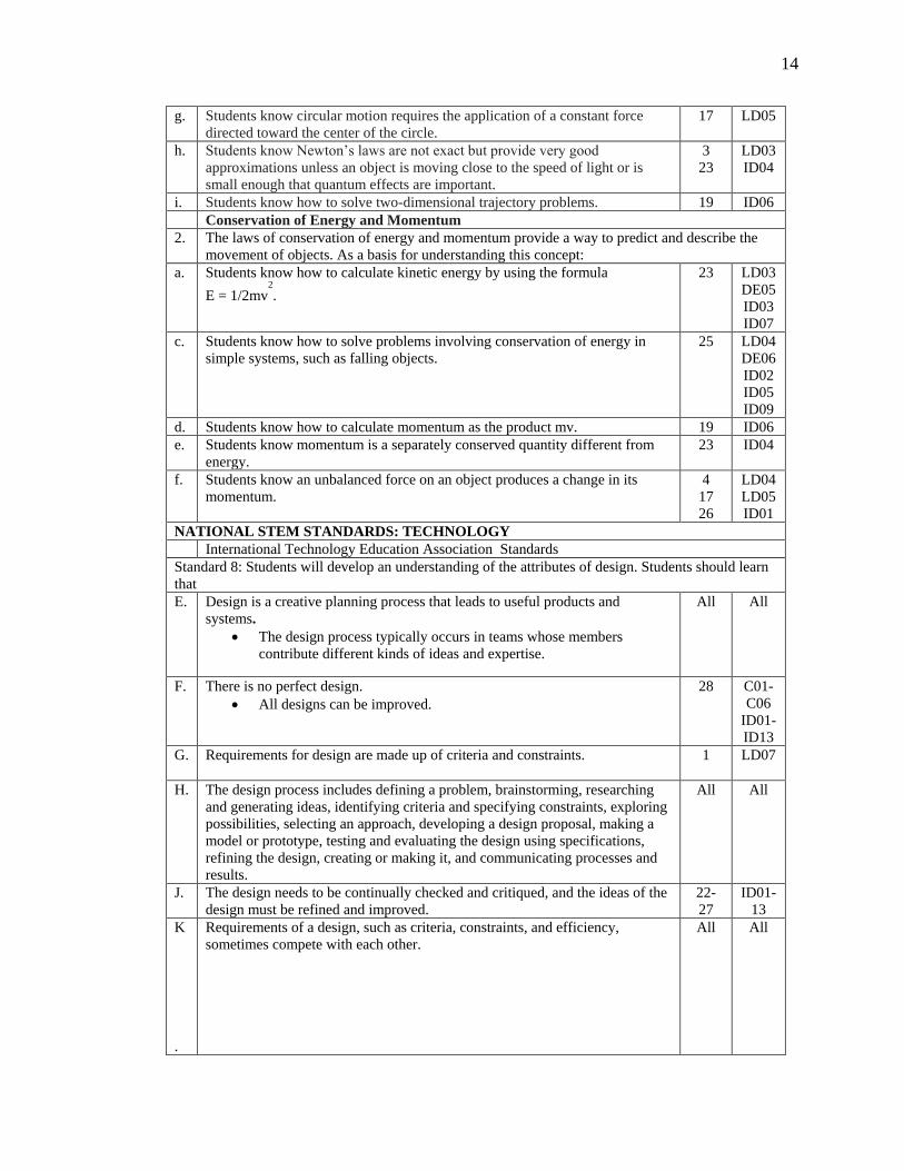
g. Students know circular motion requires the application of a constant force directed toward the center of the circle.
17 LD05
h. Students know Newton‟s laws are not exact but provide very good approximations unless an object is moving close to the speed of light or is small enough that quantum effects are important.
3 23
LD03 ID04
i. Students know how to solve two-dimensional trajectory problems. 19 ID06 Conservation of Energy and Momentum 2. The laws of conservation of energy and momentum provide a way to predict and describe the
movement of objects. As a basis for understanding this concept: a. Students know how to calculate kinetic energy by using the formula
E = 1/2mv2.
23 LD03 DE05 ID03 ID07
c. Students know how to solve problems involving conservation of energy in simple systems, such as falling objects.
25 LD04 DE06 ID02 ID05 ID09
d. Students know how to calculate momentum as the product mv. 19 ID06 e. Students know momentum is a separately conserved quantity different from
energy. 23 ID04
f. Students know an unbalanced force on an object produces a change in its momentum.
4 17 26
LD04 LD05 ID01
NATIONAL STEM STANDARDS: TECHNOLOGY International Technology Education Association Standards Standard 8: Students will develop an understanding of the attributes of design. Students should learn that E. Design is a creative planning process that leads to useful products and
systems. The design process typically occurs in teams whose members contribute different kinds of ideas and expertise.
All All
F. There is no perfect design. All designs can be improved. 28 C01-
C06 ID01- ID13
G. Requirements for design are made up of criteria and constraints. 1 LD07
H. The design process includes defining a problem, brainstorming, researching and generating ideas, identifying criteria and specifying constraints, exploring possibilities, selecting an approach, developing a design proposal, making a model or prototype, testing and evaluating the design using specifications, refining the design, creating or making it, and communicating processes and results.
All All
J. The design needs to be continually checked and critiqued, and the ideas of the design must be refined and improved.
22- 27
ID01-13
K .
Requirements of a design, such as criteria, constraints, and efficiency, sometimes compete with each other.
All All

15
Standard 9: Students develop an understanding of engineering design. Students should learn that F. design involves a set of steps, which can be performed in different sequences
and repeated as needed. Each design problem is unique and may require different procedures or demand that the stops be performed in a different sequence. In addition, engineers and designers also have their preferences and problem-solving styles and may choose to approach the design process in different ways.
15 16
C01-C06
G. brainstorming is a group problem-solving design process in which each person in the group presents his or her ideas in an open forum. In this process, no person is allowed to criticize anyone else‟s ideas
regardless of how inane they may seem. After all of the ideas are recorded, the group selects the best ones, and then further develops them.
11 LD08
H. modeling, testing, evaluating, and modifying are used to transform ideas into practical solutions. Historically, this process has centered on creating and testing
physical models. Models are especially important for the design of large items, such as cars, spacecraft, and airplanes because it is cheaper to analyze a model before the final products and systems are actually made. Evaluation is used to determine how well the designs meet the established criteria and to provide direction for refinement. Evaluation procedures range from visually inspecting to actual operating and testing products and systems.
11- 28
DE01-07
C01-06
ID01-13
I. Established design principles are used to evaluate existing designs, to collect data, and to guide the design process. The design principles include flexibility, balance, function, and
proportion. These principles can be applied in many types of design and are common to all technologies
12 14 15 16
DE01 DE02 DE03 LD04 LD05 C01-06
J. Engineering design is influenced by personal characteristics, such as creativity, resourcefulness, and the ability to visualize and think abstractly. Individuals and groups of people who possess combinations of these
characteristics tend to be good at generating numerous alternative solutions to problems. The design process often involves a group effort among individuals with varied experiences, backgrounds, and interests. Such collaboration tends to enhance creativity, expand the range of possibilities, and increase the level of expertise directed toward design problems.
1 LD07
K. A prototype is a working model used to test a design concept my making actual observations and necessary adjustments. Prototyping helps to determine the effectiveness of a design be allowing a design to be tested before it is built. Prototypes are vital to the testing and refinement of a product or system with complicated operations
11- 28
DE01-07
C01-06
ID01-13
Standard 10: Students will develop an understanding of the role of troubleshooting, research and development, invention and innovation, and experimentation in problem solving. Students should learn that F. Troubleshooting is a problem-solving method used to identify the cause of a
malfunction in a technological system. 28 ID01-
13 G .
Invention is a process of turning ideas and imagination into devices and systems. Innovation is the process of modifying an existing product or system to improve it.
All All

16
H. Some technological problems are best solved through experimentation. 18- 28
ID01-13
J. Technological problems must be researched before they can be solved. 18- 28
ID01-13
Standard 11: Students will develop abilities to apply the design process. Students should be able to H. Apply a design process to solve problems in and beyond the laboratory-
classroom. 15 16
C01- C06
I. Specify criteria and constraints for the design. 1 LD07 J. Make two-dimensional and three dimensional representations of the designed
solution. Two-dimensional examples include sketches, drawings, and computer-assisted designs (CAD).
12 15 16
DE01 C01- C06
K. Test and evaluate the design in relation to pre-established requirements, such as criteria and constraints, and refine as needed.
1 23 25
LD07 DE03 ID04
L. Make a product or system and document the solution. 2 3 15 16 24 25
C01- C06
LD04 LD07 DE05 DE06 ID02- ID09
M.
Identify the design problem to solve and decide whether or not to address it. 28 ID01-13
N. Identify criteria and constraints and determine how these will affect the design process.
1 LD07
O. Refine a design be using prototypes and modeling to ensure quality, efficiency, and productivity of the final product. Evaluate proposed or existing designs in the real world. Modify the design solution so that it more effectively solves the problem.
28 ID01-13
P. Evaluate the design solution using conceptual, physical, and mathematical models at various intervals of the design process in order to check for proper design and to note areas where improvements are needed.
2 12 22
LD02 DE01 ID01 ID04
Standard 13: Students will develop the abilities to assess the impact of products and systems. Students should be able to F. Design and use instruments to gather data. 22 ID01 G. Use data collected to analyze and interpret trends in order to identify the
positive or negative effects of technology. 28 ID01-
ID13 I. Interpret and evaluate the accuracy of the information obtained and determine
if it is useful. 28 ID01-
ID13 J. Collect information and evaluate its quality. 28 ID01-
ID13 NATIONAL STEM STANDARDS: ENGINEERING NATIONAL CONTENT STANDARDS K-12 ENGINEERING/ENGINEERING
TECHNOLOGY Dimension 1: Engineering Design Students will apply concepts of engineering design to solve problems Students will: Apply a structured approach to solving problems including: defining a
problem, brainstorming, researching and generating ideas, identifying criteria and constraints, exploring possibilities, making a model or prototype, evaluating the design using specifications, and communicating results.
11- 28
C01-06
Ask questions and make observations to help figure out how things work.
All All

17
Learn that all products and systems are subject to failure and that many products and systems can be fixed.
28 ID01-13
Troubleshoot as a way of finding out why something does not work so that it can be fixed.
18 DE07 LD06
Analyze and break down complex systems into their component parts and explain the relationship and interdependency of the part and the system.
2 LD02
Dimension 2: Connecting Engineering to Science, Technology, and Mathematics Students will develop an understanding of the essential concepts of and how to apply science, technology, and mathematics as they pertain to engineering. Students will Apply their knowledge of science, technology, engineering, and
mathematics to define, analyze, and solve problems All All
Apply contemporary engineering tools in the application of science, mathematics and technology to define analyze, model and prototype solutions to problems.
All All
Analyze a device and explain the principles of math and science used in the design.
28 ID01- ID13
Dimension 3: Nature of Engineering Students will be creative and innovative in the thought and in their actions. Students will be able to: Use a logical process for inquiry, solving practical problems, critical thinking,
and innovation. 1 LD07
Dimension 4: Communication and Teamwork Students will be able to use effective communication and teamwork skills to acquire information and convey outcomes to a variety of stakeholders. Students will be able to: Use appropriate communication procedures, including oral presentations and
written documentation using guidelines and style standards.
11
Communicate effectively using multiple media. 11 18
DE07
Practice interpersonal and group dynamic skills, such as: cooperate with others, advocate, influence, resolve conflict, and negotiate.
11
Function on multidisciplinary and crossfunctional teams. 11 NATIONAL AND CALIFORNIA STEM STANDARDS: MATH National Council of Teachers of Mathematics Standards Standard 1: Mathematics and Problem Solving In grades 5-8, the mathematics curriculum should include numerous and varied experiences with problem solving as a method of inquiry and application so that the students can –
Use problem-solving approaches to investigate and understand mathematical content;
19 20 24
ID06 ID03 ID04
Formulate problems from situations within and outside mathematics;
5 DE02 DE03 ID03 ID06
Develop and apply a variety of strategies to solve problems, with emphasis on multistep and non routine problems;
23 24 27
ID04
Verify and interpret results with respect to the original problem situation; 28 ALL Generalize solution and strategies to new problem situations; 12 DE01 Acquire confidence in using mathematics meaningfully. 5 ALL Standard 2: Mathematics and Communication In grades 5-8, the study of mathematics should include opportunities to communicate so that students can – Model situations using oral, written, concrete, pictorial, graphical, and
algebraic methods.
19 ID06
18
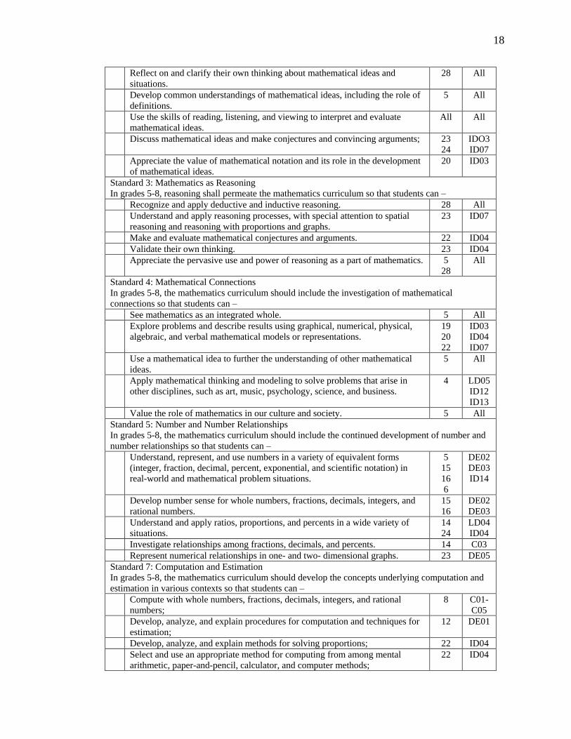
Reflect on and clarify their own thinking about mathematical ideas and situations.
28 All
Develop common understandings of mathematical ideas, including the role of definitions.
5 All
Use the skills of reading, listening, and viewing to interpret and evaluate mathematical ideas.
All All
Discuss mathematical ideas and make conjectures and convincing arguments; 23 24
IDO3 ID07
Appreciate the value of mathematical notation and its role in the development of mathematical ideas.
20 ID03
Standard 3: Mathematics as Reasoning In grades 5-8, reasoning shall permeate the mathematics curriculum so that students can – Recognize and apply deductive and inductive reasoning. 28 All Understand and apply reasoning processes, with special attention to spatial
reasoning and reasoning with proportions and graphs. 23 ID07
Make and evaluate mathematical conjectures and arguments. 22 ID04 Validate their own thinking. 23 ID04 Appreciate the pervasive use and power of reasoning as a part of mathematics. 5
28 All
Standard 4: Mathematical Connections In grades 5-8, the mathematics curriculum should include the investigation of mathematical connections so that students can – See mathematics as an integrated whole. 5 All Explore problems and describe results using graphical, numerical, physical,
algebraic, and verbal mathematical models or representations. 19 20 22
ID03 ID04 ID07
Use a mathematical idea to further the understanding of other mathematical ideas.
5 All
Apply mathematical thinking and modeling to solve problems that arise in other disciplines, such as art, music, psychology, science, and business.
4 LD05 ID12 ID13
Value the role of mathematics in our culture and society. 5 All Standard 5: Number and Number Relationships In grades 5-8, the mathematics curriculum should include the continued development of number and number relationships so that students can – Understand, represent, and use numbers in a variety of equivalent forms
(integer, fraction, decimal, percent, exponential, and scientific notation) in real-world and mathematical problem situations.
5 15 16 6
DE02 DE03 ID14
Develop number sense for whole numbers, fractions, decimals, integers, and rational numbers.
15 16
DE02 DE03
Understand and apply ratios, proportions, and percents in a wide variety of situations.
14 24
LD04 ID04
Investigate relationships among fractions, decimals, and percents. 14 C03 Represent numerical relationships in one- and two- dimensional graphs. 23 DE05 Standard 7: Computation and Estimation In grades 5-8, the mathematics curriculum should develop the concepts underlying computation and estimation in various contexts so that students can – Compute with whole numbers, fractions, decimals, integers, and rational
numbers; 8 C01-
C05 Develop, analyze, and explain procedures for computation and techniques for
estimation; 12 DE01
Develop, analyze, and explain methods for solving proportions; 22 ID04 Select and use an appropriate method for computing from among mental
arithmetic, paper-and-pencil, calculator, and computer methods; 22 ID04

19
Use computation, estimation, and proportions to solve problems; 22 ID04 Use estimation to check the reasonableness of results. 23 ID07 Standard 8: Patterns and Functions In grades 5-8, the mathematics curriculum should include exploration of patterns and functions so that students can – Describe, extend, analyze, and create a wide variety of patterns; 28 ID04 Describe and represent relationships with tables, graphs, and rules; 2 ID07 Analyze functional relationships to explain how a change in one quantity
results in a change in another; 2.b ID05
Use patterns and functions to represent and solve problems. 19 ID06 Standard 9: Algebra In grades 5-8, the mathematics curriculum should include explorations of algebraic concepts and processes so that students can – Understand the concepts of variable, expression, and equation; 19 ID06 Represent situations and number patterns with tables, graphs, verbal rules and
equations and explore the interrelationships of these representations; 2b ID07
Analyze tables and graphs to identify properties and relationships; 2b ID07 Apply algebraic methods to solve a variety of real-world and mathematical
problems. 4 LD04
DE02 Standard 10: Statistics In grades 5-8, the mathematics curriculum should include exploration of statistics in real-world situations so that students can – Systematically collect, organize, and describe data;
Construct, read, and interpret tables, charts, and graphs. 19 20 23
ID06 ID03 ID07
Make inferences and convincing arguments that are based on data analysis. 28 ID01- ID13
Develop an appreciation for statistical methods as powerful means of decision making.
28 ID01- ID13
Standard 11: Probability Model situations by devising and carrying out experiments or simulations to determine probabilities. Appreciate the power of using a probability model by comparing experimental
results with mathematical expectations; 20 ID11
Make predictions that are based on experimental or theoretical probabilities; 20 23
ID11IID07
Develop an appreciation for the pervasive use of probability in the real world. 20 ID07 Standard 12: Geometry In grades 5-8, the mathematics curriculum should include the study of the geometry of one, two, and three dimensions in a variety of situations so that students can – Indentify, describe, compare, and classify geometric figures; 12
4 DE01 ID08
Visualize and represent geometric figures with special attention to developing spatial sense;
20 ID03
Explore transformations of geometric figures; 2a ID08 Represent and solve problems using geometric models; 20 ID03 Understand and apply geometric properties and relationships; 20 ID03 Standard 13: Measurement In grades 5-8, the mathematics curriculum should include extensive concrete experiences using measurement so that students can – Extend their understanding of the process of measurement; 8 C01-
C06 Estimate, make, and use measurements to describe and compare phenomena; 21
25 ID02 ID05
Select appropriate units and tools to measure to the degree of accuracy required in a particular situation;
8 C01- C06

20
Understand the structure and use of systems and measurements; 8 12
C01- C06
DE01 Extend their understanding of the concepts of perimeter, area, volume, angle
measure, capacity, and weight and mass; 10 20 24
ID08 ID03 ID04
Develop the concepts of rates and other derived and indirect measurements; 19 20
ID06 ID03
Develop formulas and procedures for determining measures to solve problems.
28 ID01- ID13
California State Math Standards Grade 7 Math Number Sense 1.0 Students know the properties of, and compute with, rational numbers expressed in a variety of forms: 1.1
Read, write, and compare rational numbers in scientific notation (positive and negative powers of 10) with approximate numbers using scientific notation.
15 DE02 DE04
1.2
Add, subtract, multiply, and divide rational numbers (integers, fractions, and terminating decimals) and take positive rational numbers to whole-number powers.
12 DE01
1.3
Convert fractions to decimals and percents and use these representations in estimations, computations, and applications.
9 ID05
1.5
Know that every rational number is either a terminating or repeating decimal and be able to convert terminating decimals into reduced fractions.
5 12 15 16
DE01 DE02 DEO
3 CO2- C04
1.6
Calculate the percentage of increases and decreases of a quantity. 24 ID04
2.0 Students use exponents, powers, and roots and use exponents in working with fractions: 2.1
Understand negative whole-number exponents. Multiply and divide expressions involving exponents with a common base.
2.2
Add and subtract fractions by using factoring to find common denominators. 14 15 16
DE02 DE03 C03
2.3
Multiply, divide, and simplify rational numbers by using exponent rules. 2a ID08
2.4
Use the inverse relationship between raising to a power and extracting the root of a perfect square integer; for an integer that is not square, determine without a calculator the two integers between which its square root lies and explain why.
10 LD08
2.5
Understand the meaning of the absolute value of a number; interpret the absolute value as the distance of the number from zero on a number line; and determine the absolute value of real numbers.
24 ID04
Algebra and Functions 1.0 Students express quantitative relationships by using algebraic terminology, expressions, equations, inequalities, and graphs: 1.1
Use variables and appropriate operations to write an expression, an equation, an inequality, or a system of equations or inequalities that represents a verbal description (e.g., three less than a number, half as large as area A).
20 ID04

21
1.2 Use the correct order of operations to evaluate algebraic expressions such as
3(2x +52).
4 ID12
1.4 Use algebraic terminology (e.g., variable, equation, term, coefficient, inequality, expression, constant) correctly.
4 LD04
1.5 Represent quantitative relationships graphically and interpret the meaning of a specific part of a graph in the situation represented by the graph.
2b ID07
2.0 Students interpret and evaluate expressions involving integer powers and simple roots: 2.1 Interpret positive whole-number powers as repeated multiplication and
negative whole-number powers as repeated division or multiplication by the multiplicative inverse. Simplify and evaluate expressions that include exponents.
4 ID12
2.2 Multiply and divide monomials; extend the process of taking powers and extracting roots to monomials when the latter results in a monomial with an integer exponent.
4 ID12
3.0 Students graph and interpret linear and some nonlinear functions: 3.2 Plot the values from the volumes of three-dimensional shapes for various
values of the edge lengths (e.g., cubes with varying edge lengths or a triangle prism with a fixed height and an equilateral triangle base of varying lengths).
4 ID12
3.3 Graph linear functions, noting that the vertical change (change in y-value) per unit of horizontal change (change in x-value) is always the same and know that the ratio (“rise over run”) is called the slope of a graph.
19 20
ID06 ID03
3.4 Plot the values of quantities whose ratios are always the same (e.g., cost to the number of an item, feet to inches, circumference to diameter of a circle). Fit a line to the plot and understand that the slope of the line equals the quantities.
19 20
ID06 ID03
4.0 Students solve simple linear equations and inequalities over the rational numbers: 4.2 Solve multistep problems involving rate, average speed, distance, and time
or a direct variation. 19 23 24
ID06 ID03 ID04
Measurement and Geometry 1.0 Students choose appropriate units of measure and use ratios to convert within and between measurement systems to solve problems: 1.1 Compare weights, capacities, geometric measures, times, and temperatures
within and between measurement systems (e.g., miles per hour and feet per second, cubic inches to cubic centimeters).
19 ID06
1.2 Construct and read drawings and models made to scale. 12 DE01
2.0 Students compute the perimeter, area, and volume of common geometric objects and use the results to find measures of less common objects. They know how perimeter, area, and volume are affected by changes of scale: 2.1 Use formulas routinely for finding the perimeter and area of basic two-
dimensional figures and the surface area and volume of basic three-dimensional figures, including rectangles, parallelograms, trapezoids, squares, triangles, circles, prisms, and cylinders.
2a 4
ID08 ID12
2.2 Estimate and compute the area of more complex or irregular two- and three-dimensional figures by breaking the figures down into more basic geometric objects.
4 ID12
22
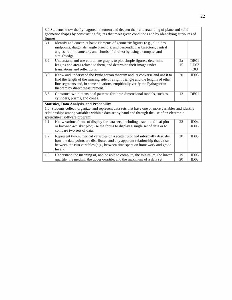
3.0 Students know the Pythagorean theorem and deepen their understanding of plane and solid geometric shapes by constructing figures that meet given conditions and by identifying attributes of figures: 3.1 Identify and construct basic elements of geometric figures (e.g., altitudes,
midpoints, diagonals, angle bisectors, and perpendicular bisectors; central angles, radii, diameters, and chords of circles) by using a compass and straightedge.
3.2 Understand and use coordinate graphs to plot simple figures, determine lengths and areas related to them, and determine their image under translations and reflections.
2a 15
DE01 LD02 C03
3.3 Know and understand the Pythagorean theorem and its converse and use it to find the length of the missing side of a right triangle and the lengths of other line segments and, in some situations, empirically verify the Pythagorean theorem by direct measurement.
20 ID03
3.5 Construct two-dimensional patterns for three-dimensional models, such as cylinders, prisms, and cones.
12 DE01
Statistics, Data Analysis, and Probability 1.0 Students collect, organize, and represent data sets that have one or more variables and identify relationships among variables within a data set by hand and through the use of an electronic spreadsheet software program: 1.1 Know various forms of display for data sets, including a stem-and-leaf plot
or box-and-whisker plot; use the forms to display a single set of data or to compare two sets of data.
22 ID04 ID05
1.2 Represent two numerical variables on a scatter plot and informally describe how the data points are distributed and any apparent relationship that exists between the two variables (e.g., between time spent on homework and grade level).
20 ID03
1.3 Understand the meaning of, and be able to compute, the minimum, the lower quartile, the median, the upper quartile, and the maximum of a data set.
19 20
ID06 ID03

23
CHAPTER 3LESSONS Lecture and Demonstration The lecture and demonstration series of lessons are designed to give the students a basic understanding of the model rocket, Newton‟s Laws of Motion, aeronautics, rocket stability, the rules of the Team America Rocketry Challenge, and model rocketry safety rules. The lectures are given with a PowerPoint Presentation with the students taking notes. The lectures should occur early in the class as knowledge gained by the students will be used throughout the curriculum.

24
LECTURE & DEMONSTRATION Topic:
LD01: Introduction to Rocketry
Content:
Overview of class, Introduction to the Team America Rocketry Challenge
Materials Student: Student Handbook Teacher: PowerPoint presentation: LL01; Introduction to Rocketry, TARC DVD, equipment to show presentation
Procedures: 1. Welcome, Introduction of instructors & students. 2. Hand out student handbook . 3. Lecture on the class outline, the Team America Rocketry Challenge 4. View a portion of a TARC finals DVD.
Practice: None
Activities: Group Activities: Students will discuss what they observed on the DVD
presentation.
Assessment: Teacher will ask questions and engage in discussion to check for understanding.
Modification: As needed for individual students
References: Class Outline (Aerospace Industries Association, 2009) (National Association of Rocketry, 2008)

25
Lecture & Demonstration Topic:
LD02: The Model Rocket
Content:
The parts of a model rocket and their function.
Materials
LL02 PowerPoint Presentation, Equipment to show presentation, a model rocket with a payload section, rocket engine, parachute.
Procedures:
1. The teacher will give the PowerPoint presentation of the model rocket using a built model rocket as an example.
Practice:
The students will handle various model rockets and identify the parts.
Activities:
Group Activities: none
Individual Activities: Each student will take notes in the student handbook.
Assessment:
Teacher will ask questions and engage in discussion to check for understanding. Students will be given a written test on the information.
Modification:
As needed for individual students
References: (Van Milligan, 2008) (Canepa, 2005) (Stine & Stine, 2004)

26
Lecture & Demonstration Topic:
LD03: Newton’s Laws of Motion
Content:
An explanation of Newton‟s three laws of motion.
Materials (Aids/AV/Software/Student Supplies): PowerPoint presentation on Newton‟s Laws of Motion, NASA video clip on Newton‟s Laws of Motion, computer, projector, sound system, Student Handbook
Procedures: 1. The teacher will give a lecture using the following PowerPoint presentation while students take notes in their handbook:
2. If needed, the students will view a short video on the Wright brothers and the laws of motion.
Practice:
Students will engage in hands-on activities that demonstrate the laws of motion.
Activities:
Group Activities: Balloon Thrust Experiment
Individual Activities: Each student will take notes in the student handbook.
Assessment: Teacher will ask questions and engage in discussion to check for understanding. Students will be assessed using appropriate STEM content standards.
Modification: As needed for individual students
References: (National Aeronautics and Space Administration, 2005) (Robertson, 2002) (Cannon, 1998) (Nolte, 1994) (Cannon, 1970) (Shearer et al., 2007)

27
Lecture & Demonstration Topic:
LD04: Aerodynamics
Content:
four forces of flight: lift, drag, weight (gravity), thrust
Materials (Aids/AV/Software/Student Supplies): PowerPoint presentation on Newton‟s Laws of Motion, NASA video clip on four forces of flight, computer, projector, sound system, Student Handbook
Procedures: 1. The teacher will give a lecture LD04, Aerodynamics. 2. If needed, the students will view a short video on the Wright brothers and the
four forces of flight.
Practice: The students will use knowledge gained from this lesson to successfully fly their model rocket.
Activities:
Group Activities: Students will fly their model rockets as a group.
Individual Activities: Each student will take notes in the student handbook.
Assessment: Teacher will ask questions and engage in discussion to check for understanding. Students will be assessed using appropriate STEM content standards.
Modification: As needed for individual students
References: (National Aeronautics and Space Administration, 2005) (Stine & Stine, 2004) (Nolte, 1992) (Mandell, Caporaso & Bengan, 1973) (Cannon, 1970)

28
Lecture & Demonstration Topic:
LD05: Rocket Stability
Content:
Center of gravity, rocket rotations, center of pressure, rocket stability, weathercocking.
Materials (Aids/AV/Software/Student Supplies): PowerPoint presentation on Rocket Stability, computer, projector, model rocket for demonstrative purposes, Student Handbook
Procedures: 1. The teacher will give a lecture LD05, Rocket Stability
Practice: The students will use knowledge gained from this lesson to successfully fly their model rocket.
Activities: Group Activities: Toy Balloon Experiment – adding fins
Individual Activities: Each student will take notes in the student handbook.
Assessment: Teacher will ask questions and engage in discussion to check for understanding. Students will be assessed using appropriate STEM content standards.
Modification: As needed for individual students
References: (National Aeronautics and Space Administration, 2005) (Stine & Stine, 2004) (Estes, 1999) (Mandell, Caporaso & Bengan, 1973) (Nolte, 1994)

29
Lecture & Demonstration
Topic:
LD06: Launch Procedures
Content:
Students learn and practice the launch procedures for the class.
Materials
Launch Equipment, Data Collection Instruments, Launch procedures script, flight log, meteorology log, tracking station log, two way radios.
Procedures: 1. Assign students to positions. 2. In Class Walkthrough – (Day 1)
1. Hand out Appendix C, Countdown procedures. 2. The class will read the procedures out loud while the teacher pauses
the reading to elaborate what is occurring at that point of the countdown.
3. Repeat as necessary.
3. Dry Run with Equipment – (Day 2) 1. Issue the equipment to the students. 2. Set up the equipment in a small area so that all students may hear the
teacher without the two-way radios. 3. Walk through the countdown with the students, explaining each step. 4. Repeat the launch procedures in real time while simulating a launch.
4. First Launch – (Day 3) 1. Conduct a launch using one rocket. Ensure that all students are
familiar with their assignments. 2. Conduct a post launch discussion about the launch, answer questions,
and clarify procedures.
Practice: The students will set up the launch equipment and data collection instruments and conduct a dry run.
Activities: Group Activities: The students will conduct a dry run of the launch procedures.
Individual Activities: Each student will have a specific assignment and must learn to operate any instruments or equipment pertaining to the assignment.
Assessment: Teacher will ask questions and engage in discussion to check for understanding. Students will be assessed using appropriate STEM content standards.
Modification: As needed for individual students
References: Model Rocketry Safety Rules

30
Lecture & Demonstration Topic:
LD07: TARC Rules
Content:
A review of the Team America Rocketry Challenge Rules
Materials
Current TARC rules
Procedures: 1. The teacher will discuss the TARC rules for the current competition. 2. The teacher will lead a discussion of the rules and assist the students in
interpreting them.
Practice:
1. The students will design, build, and fly their rocket based on the TARC rules.
Activities: Group Activities: The students will brainstorm ideas about rocket designs that would be successful under the TARC rules.
Individual Activities: Each student will take notes in the student handbook.
Assessment: Teacher will ask questions and engage in discussion to check for understanding. Students will be assessed using appropriate STEM content standards.
Modification: As needed for individual students
References: (Aerospace Industries Association, 2009)

31
Lecture & Demonstration
Topic:
LD08: Model Rocketry Rules
Content:
Safety rules on model rocketry.
Materials
Rocketry rules in Student Handout
Procedures:
1. The class will review the Model Rocketry Safety Rules.
Practice:
The students will adhere to the model rocketry safety code during all class activities.
Activities:
Individual Activities: Each student will take notes in the student handbook.
Assessment: Teacher will ask questions and engage in discussion to check for understanding. Students will be assessed using appropriate STEM content standards.
Modification: As needed for individual students
References: (National Association of Rocketry, 2009)

32
Notes to Lecture & Demonstration Lessons
LD01: Introduction to Model Rocketry
The Team America Rocketry Challenge The Team America Rocketry Challenge (TARC) was conceived originally as a way to
promote interest in science and aerospace careers among high school students, and to celebrate the 100th anniversary of the Wright brothers‟ 1903 flight. The response was so great that it became an annual event. Approximately 7,000 students from across the nation compete in TARC each year. The Team America Rocketry Challenge is an aerospace design and engineering event for teams of US secondary school students (7th through 12th grades) run by the NAR and the Aerospace Industries Association (AIA). Teams can be sponsored by schools or by non-profit youth organizations such as Scouts, 4-H, or Civil Air Patrol (but not the NAR or other rocketry organizations). The goal of TARC is to motivate students to pursue aerospace as an exciting career field, and it is co-sponsored by the American Association of Physics Teachers, 4-H, the Department of Defense, and NASA. The event involves designing and building a model rocket (2.2 pounds or less, using NAR-certified model rocket motors totaling no more than 80.0 Newton-seconds of total impulse) that carries a payload of 1 Grade A Large egg for a flight duration of 40 - 45 seconds, and to an altitude of exactly 825 feet (measured by an onboard altimeter), and that then returns the egg to earth undamaged using only a streamer as a recovery device. Onboard timers are allowed; radio-control and pyrotechnic charges are not.
The first seven Team America Rocketry Challenges, held in 2003 through 2009, were the largest model rocket contests ever held. Co-sponsored by the NAR and the Aerospace Industries Association (AIA), the five events together attracted about 5,100 high-school teams made up of a total of over 50,000 students from all 50 states. These students had a serious interest in learning about aerospace design and engineering through model rocketry. The top 100 teams each year came to a final fly-off competition in late May near Washington, DC, to compete for $60,000 in prizes. These teams were selected based on the scores reported from qualification flights that they conducted locally throughout the US.
Team America Rocketry Challenge 2010's target flight duration of 40-45 seconds is measured from the moment of rocket liftoff until the egg payload lands. The target flight altitude of 825 feet is measured by an onboard altimeter. The top 100 teams from among all those who have entered will meet in a final fly-off competition on May 15, 2010 at Great Meadow, The Plains, VA. These top 100 teams will be selected based on the duration and altitude scores reported from local qualification flights that they conduct in front of an NAR Senior (adult) member observer at their choice of time, up until the flight deadline of April 5, 2010.
NAR The National Association of Rocketry (NAR) is the organized body of rocket hobbyists. Chartered NAR sections conduct launches, connect modelers and support all forms of sport
33
rocketry. NAR was founded in 1957 to help young people learn about science and math through building and safely launching their own models.
4H 4-H has grown into a community of 6 million young people across America learning leadership, citizenship and life skills. 4-H can be found in every county in every state, as well as the District of Columbia, Puerto Rico and over 80 countries around the world. The 4-H community also includes 3,500 staff, 518,000 volunteers and 60 million alumni. 4-H'ers participate in fun, hands-on learning activities, supported by the latest research of land-grant universities, that are focused on three areas called Mission Mandates: Science, Engineering and Technology, Healthy Living and Citizenship.
The NAR 4H partnership In May 2007 the NAR and 4-H initiated a national partnership. The purpose of this alignment is to get more kids to fly rockets and form rocket clubs which will lead to more TARC teams, more people joining NAR and more kids becoming scientists and engineers Together 4H clubs and NAR sections can hold sport, contest or TARC launches. They can have training and building sessions, or work on science fair and engineering challenges using rocketry. 4H has many 'state fair' events that need innovative ideas for student projects. In serving young people 4H and NAR can both elevate the visibility of one another in their mutual community. The NAR has a wide range of online resources that are immediately useful to 4-H youth group leaders in organizing and running rocketry programs. NAR board members have had several planning meetings with the 4H National Council and Headquarters Directors. The first steps to implementing these plans are to establish connections between the organizations, such as this web link. Members from both groups need to get familiar with each other. As a few joint rocketry activities get started and promoted in some regions, other areas will get the idea and follow. 4H teams will eventually become big players in TARC. The goal is that in five years the partnership will have engaged over 100,000 students in a rocketry event.

34
LD02: The Model Rocket
THE BOOSTER SECTION • Launch Lug – helps to guide the
rocket upward until it reaches enough velocity for the fins to engage.
• Parachute – assists in the safe recovery of the rocket.
• Shock Cord – connects the parachute and nosecone to the booster. It absorbs the shock of ejection charge.
• Shock Cord Attachment – attaches the shock cord to the booster section.
• Centering Rings – attach the engine mount (and sometimes the fins) to the airframe.
• Engine Mount – holds the rocket engine inside the rocket.
• Engine Retainer – prevents the engine from being ejected by the ejection charge.
• Fins – guides the rocket in a straight path.

35
Fin Edges & Shapes
Rectangular: Simple to make, least aerodynamic
Swept: Simple to make, slightly better aerodynamics
TaperedSwept: Moves Center of Pressure back, good design for fast moving rockets.
ClippedDelta: Good aerodynamic fin, used on low-drag, high-performance rockets
Trapezoidal: Good aerodynamic fin for payload rockets, moves the Center of Pressure forward.
Elliptical: Best aerodynamic fin, difficult to construct.
36
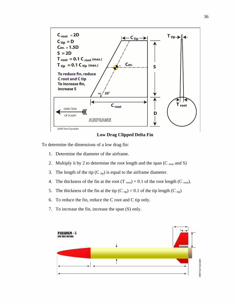
Low Drag Clipped Delta Fin
To determine the dimensions of a low drag fin:
1. Determine the diameter of the airframe.
2. Multiply it by 2 to determine the root length and the span (C root and S)
3. The length of the tip (C tip) is equal to the airframe diameter.
4. The thickness of the fin at the root (T root) = 0.1 of the root length (C root).
5. The thickness of the fin at the tip (C tip) = 0.1 of the tip length (C tip)
6. To reduce the fin, reduce the C root and C tip only.
7. To increase the fin, increase the span (S) only.

37
Low Drag, High Performance Rocket
The Paradigm–5 is an example of a low-drag, high performance model rocket design that uses a low-drag clipped delta fin.
Payload Section • Nose – creates an aerodynamic
shape. May also hold a payload. • Airframe – holds the payloads
in place. • Bulkhead – separates the egg
section from the electronics section, preventing vortex effect and causing a false altimeter reading.
• Altimeter – measures the changing air pressure to calculate apogee. Must have vent holes in airframe in order to operate properly.
• Tube Coupler – connects the payload section to the booster section by means of the shock cord. Also protects the payload from the ejection gases.
• Shock Cord Attachment – a metal eye for the secure attachment of the shock cord.

38
The Egg • Eggs have an „arch structure‟ at
each end that transfers pressure to the sides.
• About 35 Newtons of force is required to break an egg on its end and about 25N to break it on its side.
Nose Shape
Rocket noses are made of balsa, plastic, or fiberglass. For aircraft and rockets, below Mach .8, the nose pressure drag is essentially zero for all shapes and the major significant factor is friction drag. Having a smooth finish on the nose is more important than nose shape for rockets flying under the speed of sound.

39
Rocket Motor Sizes
• Motor diameter is measured in millimeters.
• Sizes for low to mid-power rockets are 13mm, 18mm, 24mm, and 29mm.
Engine or Motor?
• Something that imparts motion is called a motor.
• An engine is a machine that converts energy into mechanical motion.
• While referring to the propulsion system of a model rocket as a motor is more accurate, the use of the term engine is common.
Black Powder Motor
B– The letter indicates the total impulse power produced by the motor. Each letter doubles the power.
6 – The first number gives the average thrust of the motor in Newtons.
4 – The last number indicates the delay seconds between the end of thrust and the ejection charge.
Black Powder Motor Burn • Black powder motors burn from the rear forward. • When the propellant is spent, it ignites the delay charge. • The delay charge burns forward and ignites the ejection charge. • The clay nozzle forces the pressure forward, expelling the nose cone and
recovery system.

40
The parts of a Composite Reloadable Engine:
• The case is a reusable part that holds the propellant. Also reusable are the forward and aft closure.
• The nozzle is only used once and directs the thrust rearward. • The composite propellant grain is a spongy material that does not break if
dropped. It is the same type of propellant used in the NASA Space Shuttle boosters.
• The igniter is pushed all the way forward into the propellant grain. • The delay element is installed inside the forward closure. • The black powder ejection charge is held in place by a plastic cap.
Composite Motor Burn
• Composite motors burn from the inner core out. • The delay element is ignited with the propellant and burns forward. Because of
this, tracking smoke is produced immediately. • The delay element ignites the ejection charge.

41
Parachute
Parachutes are made out of plastic, Mylar, or rip-stop nylon. Shroud lines can be carpet thread or Kevlar chord. The spill hole reduces oscillation and increased descent rate. Oscillation is a swaying motion as the parachute spills air from its sides. Adding a riser lifts the parachute out of the turbulence of the rocket, but increases the risk of parachute failure.
Streamers
Streamers are made out of crepe paper, Mylar, Dura-Lar, or rip-stop nylon. The best length to width radio is 10:1 to create the most drag as the streamer flaps in the wind. Streamer recovery is faster than parachute recovery and reduces the recovery area.

42
LD03: Newton’s Laws of Motion Sir Isaac Newton was an English physicist, mathematician, astronomer, natural philosopher, and alchemist. In 1666, he witnessed an apple fall from its tree and he began to ponder why it fell down. This led to his Three Laws of Motion. First Law of Motion: The Law of Inertia Every body perseveres in its state of being at rest or of moving uniformly straight forward, except insofar as it is compelled to change its state by force impressed. Objects at rest will stay at rest (inertia) and objects in motion will stay in motion in a straight line unless acted upon be an unbalanced force. There is a natural tendency of objects to keep on doing what they're doing. All objects resist changes in their state of motion. In the absence of an unbalanced force, an object in motion will maintain this state of motion. Second Law of Motion: The Law of Force The change of momentum of a body is proportional to the impulse impressed on the body, and happens along the straight line on which that impulse is impressed. Acceleration is produced when a force acts on a mass. The greater the mass (of the object being accelerated) the greater the amount of force needed (to accelerate the object). F = MA Force = Mass times Acceleration A car that weighs 1,000 kg runs out of gas. The driver pushes the car to a gas station at a speed of 0.05 meters per second. How much force is the driver applying to the car to go that speed? F = 1,000 kg x 0.05 m/s/s F = 50 Newtons of force
What the heck is a Newton? The Newton is a unit of force. It is equal to the amount of force required to accelerate a mass of one kilogram at a rate of one meter per second per second. What the heck is a kilogram? 1 Kilo = 2.2 pounds

43
You Know The 2nd Law Already! Everyone knows the Second Law: heavier objects require more force to move the same distance as lighter objects. We know that we don‟t need the same amount of force to lift a feather that is needed to lift a bowling ball. Third Law of Motion: The Law of Reciprocal Actions For a force there is always an equal and opposite reaction: or the forces of two bodies on each other are always equal and are directed in opposite directions. For every action, there is an equal and opposite reaction. This means that for every force there is a reaction force that is equal in size, but opposite in direction. Whenever an object pushes another object it gets pushed back in the opposite direction with equal force.
44
LD04: Aerodynamics
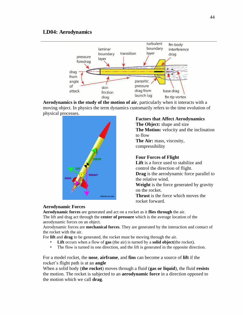
Aerodynamics is the study of the motion of air, particularly when it interacts with a moving object. In physics the term dynamics customarily refers to the time evolution of physical processes.
Factors that Affect Aerodynamics The Object: shape and size The Motion: velocity and the inclination to flow The Air: mass, viscosity, compressibility Four Forces of Flight Lift is a force used to stabilize and control the direction of flight. Drag is the aerodynamic force parallel to the relative wind. Weight is the force generated by gravity on the rocket. Thrust is the force which moves the rocket forward.
Aerodynamic Forces Aerodynamic forces are generated and act on a rocket as it flies through the air. The lift and drag act through the center of pressure which is the average location of the aerodynamic forces on an object. Aerodynamic forces are mechanical forces. They are generated by the interaction and contact of the rocket with the air. For lift and drag to be generated, the rocket must be moving through the air.
• Lift occurs when a flow of gas (the air) is turned by a solid object(the rocket). • The flow is turned in one direction, and the lift is generated in the opposite direction.
For a model rocket, the nose, airframe, and fins can become a source of lift if the rocket‟s flight path is at an angle When a solid body (the rocket) moves through a fluid (gas or liquid), the fluid resists the motion. The rocket is subjected to an aerodynamic force in a direction opposed to the motion which we call drag.

45
drag is aerodynamic friction, and one of the sources of drag is the skin friction between the molecules of the air and the solid surface of the moving rocket. A boundary layer is the layer of air in the immediate vicinity of the rocket‟s surface. Boundary layers can be laminar (smooth flow) or turbulent (swirling). The point in which a laminar boundary layer becomes turbulent is called the transition. drag is also aerodynamic resistance to the motion of the object through the fluid. This source of drag depends on the shape of the rocket and is called pressure or form drag. Interference drag occurs whenever two surfaces meet at sharp angles, such as at the fin roots. Interference drag creates a vortex which creates drag. Fin fillets reduce the effects of this drag. Air passing by the tips of the fins form a fin tip vortex. Accelerating the air into this vortex causes drag on the fins, and a low pressure area behind them. Tapered fin tips reduce this drag. Parasitic Drag is produced by objects like the launch lug. The launch lug can account for 30% of all drag. Cutting the lug‟s leading edge to 45 degrees reduces drag.

46
A model rocket‟s fin that is square on the edges creates a lot of drag and turbulence. If the fin‟s leading and trailing edges are sanded in a roundshape, called an airfoil, it reduces the drag. airfoil shape fins creates high pressure behind the fin and pushes it forward, cancelling out most of the pressure drag caused by the fins. This is called pressure recovery.
Weight is the force generated by the gravitational attraction on the rocket. The gravitational force is a field force; the source of the force does not have to be in physical contact with the object. Gravity affects the rocket whether it is stationary or moving (up or down). Thrust is the force applied to the rocket to move it through the air, and through space. Thrust is generated by the propulsion system of the rocket through the application of Newton's Third Law of Motion. The direction of the thrust is normally along the longitudinal axis of the rocket through the rocket‟s center of gravity.

47
LD05: Rocket Stability
During the flight of a model rocket, gusts of wind or thrust instabilities, can cause the rocket to "wobble", or change its attitude in flight. Poorly built or designed rockets can also become unstable in flight. This lesson is about what makes a rocket unstable in flight and what can be done to improve its stability. Translation and Rotation A rocket in flight can move two ways; it can translate, or change its location from one point to another, and it can rotate, meaning that it can roll around on its axis. Roll Most rockets are symmetric about a line from the tip of the nose to the center of the nozzle exit. We will call this line the roll axis and motion about this axis is called a rolling motion. The center of gravity lies along the roll axis. Yaw and Pitch When a rocket wobbles from side to side, this movement is called a yaw motion. A pitch motion is an up or down movement of the nose of the rocket.
Center of Gravity – CG As a rocket flies through the air, it both translates and rotates. The rotation occurs about a point called the center of gravity, which is the average location of the weight of the rocket.
How to Determine the Center of Gravity
1. Load the motor, recovery system, and payload. 2. Tie a string around the airframe and adjust it until the rocket is horizontally
balanced. 3. The location of the string is the center of gravity.

48
Center of Pressure – CP The average location of the pressure on the rocket is called the center of pressure. The parts of the rocket that influences the location of the center of pressure the most are the fins.
Building a Stable Rocket
If the center of gravity is in front of the center of pressure, the rocket will return to its initial flight conditions if it is disturbed. This is called a restoring force because the forces "restore" the rocket to its initial condition and the rocket is said to be stable.
If the center of gravity and the center of pressure are in the same location, it is called neutral stability. A rocket with neutral stability may make a stable or unstable flight depending on the forces acting on it.
If the center of pressure is in front of the center of gravity, the lift and drag forces maintain their directions but the direction of the torque generated by the forces is reversed. This is called a de-stabilizing force. Any small displacement of the nose generates forces that cause the displacement to increase. Such a flight condition is unstable.

49
Correcting Unstable Flight To move the Center of Gravity:
• Add or remove weight in the nose cone. • Redistribute the Payload • Increase or decrease airframe length.
To move the Center of Pressure: • Increase or reduce the fin size. • Change the shape of the fins. • Change the location of the fins. • Increase or decrease airframe length/diameter
One Caliber Stability The best separation between the center of gravity and the center of pressure is for the CP to be at least one body tube diameter in front of the CG. This is called one caliber stability. Weather Cocking • Following the liftoff of a model rocket, it often turns into the wind. This
maneuver is called weather cocking and it is caused by forces, such as a strong wind, pushing on the side of the rocket‟s fins.
Causes of Weather Cocking • Rockets with long airframes experience weather cocking, especially during the
coast phase. • Large fins present a larger surface area for the wind. • Rockets with a center of gravity that is far in front of the center of pressure.
Tube Fins • Using tube fins reduce weather cocking because of the aerodynamic side profile. • Tube fins should be used carefully because these types of rockets tend to be
unstable.
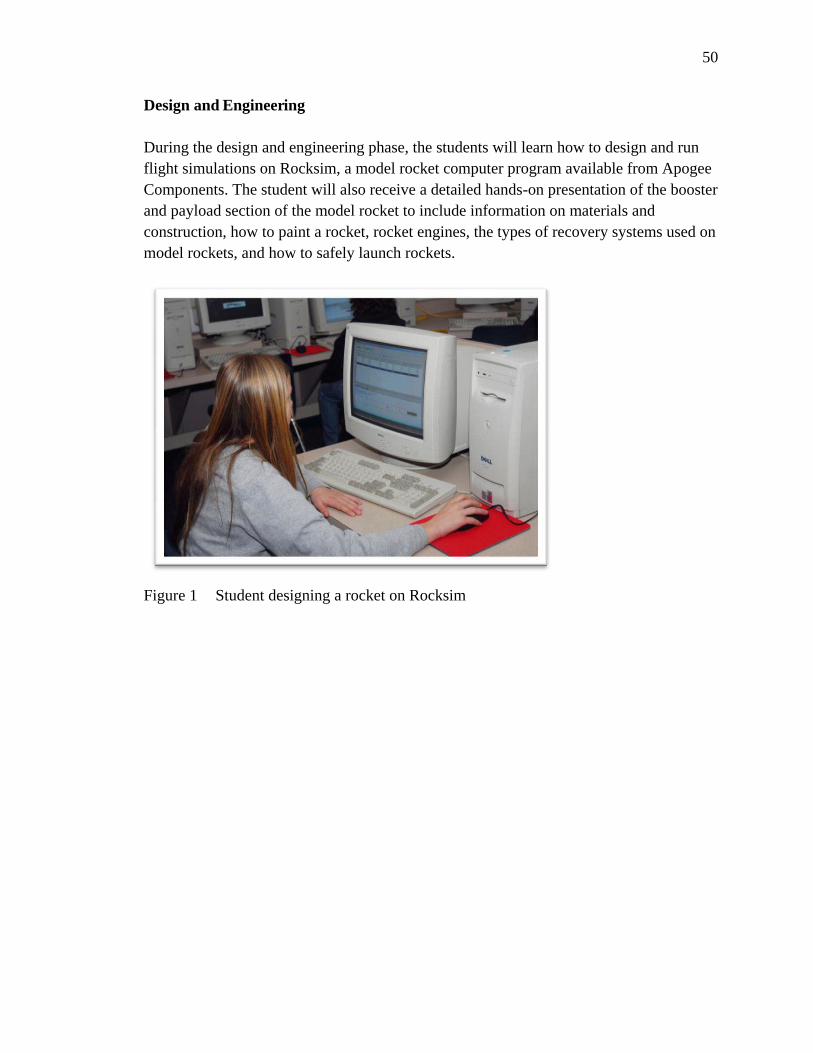
50
Design and Engineering During the design and engineering phase, the students will learn how to design and run flight simulations on Rocksim, a model rocket computer program available from Apogee Components. The student will also receive a detailed hands-on presentation of the booster and payload section of the model rocket to include information on materials and construction, how to paint a rocket, rocket engines, the types of recovery systems used on model rockets, and how to safely launch rockets.
Figure 1 Student designing a rocket on Rocksim

51
Design & Engineering Topic:
DE01: Introduction to Rocksim
Content:
Designing a model rocket on the computer
Materials:
Computer and a copy of Rocksim for each student, Student Handbook
Procedures: The teacher will demonstrate in a step by step process how to design a model rocket, load and engine, and run flight simulations.
Practice: Students will run simulations and make changes to their rocket design to improve
performance. Activities: Group Activities: The students can have a virtual model rocketry contest with their
Rocksim designs. Individual Activities: Students will design their own rocket and test the design in flight
simulations.
Assessment: Teacher will ask questions and engage in discussion to check for understanding. Students will be assessed using appropriate STEM content standards.
Modification:
As needed for individual students.
References: Rocksim Help Manual

52
Design & Engineering Topic:
DE02: The Booster Section
Content:
Fin design and construction, through the tube fins, fin fillets, body tubes, engine mounts, shock code attachment, launch lugs and rails
Materials:
Examples of fins and fin material, craft, HD, and phenolic tubes, engine mount parts; engine mounts, centering rings, engine blocks, engine hooks and retention systems, launch lugs and rails, epoxy, glue, ca glue, card stock, wood filler
Procedures: 1. The teacher will present each part of the booster section and demonstrate construction techniques. To include: Fin design and construction Fin reinforcement methods Engine mount design and construction How to select and use epoxy and other adhesives Through the Tube Fins (TTF) Shock cords and their attachment
2. Demonstration of cutting body tubes for “through the body” fins
Practice:
Students will use skills to built the own rocket.
Activities: Group Activities: TARC team members will work as a group in the design and construction of their TARC rocket.
Individual Activities: Students will use knowledge gained from lesson in the construction of their own rockets.
Assessment: Teacher will ask questions and engage in discussion to check for understanding. Students will be assessed using appropriate STEM content standards.
Modification:
As needed for individual students.
References: (Van Milligan, 2008) (Canepa, 2005) (Stine & Stine, 2004)

53
Design & Engineering Topic:
DE03: The Payload Section
Content:
Construction of a payload section on a model rocket.
Materials
Examples of nose cones, body tubes of various sizes and materials, bulkheads, altimeter, egg, cushion materiel, hardware.
Procedures: 1. The teacher will present each part of the payload section and demonstrate construction techniques. Nose cone shapes, materials, and selection Body tube sizes and selection. Cutting body tubes. Bulkhead selection and installation. Vent hole placement and drilling.
2. Altimeter installation and operation.
3. A review of the chicken egg.
Practice: Students will use skills to built the own rocket.
Activities: Group Activities: TARC team members will work as a group in the design and construction of their TARC rocket.
Individual Activities: Students will use knowledge gained from lesson in the construction of their own rockets.
Assessment: Teacher will ask questions and engage in discussion to check for understanding. Students will be assessed using appropriate STEM content standards.
Modification: As needed for individual students.
References: (Van Milligan, 2008) (Canepa, 2005) (Stine & Stine, 2004)

54
Design & Engineering Topic:
DE04: Painting and Finishing
Content:
The best methods for creating aerodynamic surfaces.
Materials:
Unfinished model, wood filler, wood sealer, spray cans of primer and enamel paint, clear coat, model rockets in various stages of finish.
Procedures: 1. The teacher will demonstrate the process of applying a finish to a model rocket. For the sake of time, discuss the technique and show examples.
2. Supervise the students throughout the finishing process.
Practice:
Students will apply a finish to their own rockets during construction.
Activities: Group Activities: TARC team members will work as a group in the design and construction of their TARC rocket.
Individual Activities: Students will use knowledge gained from lesson in the construction of their own rockets.
Assessment: Teacher will ask questions and engage in discussion to check for understanding. Students will be assessed using appropriate STEM content standards.
Modification: As needed for individual students.
References: (Van Milligan, 2008) (Canepa, 2005) (Stine & Stine, 2004)

55
Design & Engineering Topic:
DE05: Rocket Engines
Content:
A detailed look at model rocket engines
Materials:
Examples of rocket engine, model rocket engine static display.
Procedures: 1. Give lessons and demonstrations that include: the types of available rocket engines motor nomenclature single use and reloadable engines how to read a thrust curve how to build a reloadable engine, engine retainer systems clustering staged rockets
Practice:
The students will choose and load rocket motors into their own rockets.
Activities: Group Activities: TARC teams will use this information to design and build their competition rocket.
Individual Activities: Students will use knowledge gained from lesson in the construction of their own rockets.
Assessment: Teacher will ask questions and engage in discussion to check for understanding. Students will be assessed using appropriate STEM content standards.
Modification: As needed for individual students.
References: (Van Milligan, 2008) (Stine & Stine, 2004) (Estes, 1999)

56
Design & Engineering Topic:
DE06: Recovery Systems
Content:
Types of recovery, parachutes and streamers
Materials:
Examples of recovery systems including, parachutes with and without spill holes and of different material, examples of streamers.
Procedures: 1. The teacher will describe and discuss each type of recovery system.
2. The teacher will demonstrate the various types of parachutes and streamers.
Practice: The students will practice the use of recovery systems during lesson ID02, Investigating Parachutes, ID09, Investigating Streamers, and ID05, Adjusting Descent Rate Using Parachutes & Streamers
Activities: Group Activities: TARC teams will use this information to design and build their competition rocket.
Assessment: Teacher will ask questions and engage in discussion to check for understanding. Students will be assessed using appropriate STEM content standards.
Modification: As needed for individual students.
References: (Van Milligan, 2008) (Stine & Stine, 2004)

57
Design & Engineering Topic:
DE07: Model Rocket Launch Equipment
Content:
A review of available launch equipment.
Materials:
Example of launch pads using rods and rails, 6v and 12v ignition systems
Procedures: 1. The teacher will describe and discuss various types of launch equipment to include launch 1/8”, 3/8”, and ¼” launch rods, launch pads, launch rail, 6 volt and 12 volt ignition systems.
Practice:
The students will gain experience with the launch equipment during launches.
Activities: Group Activities: TARC teams will use this information to select a launch system for their competition rocket.
Individual Activities: none
Assessment: Teacher will ask questions and engage in discussion to check for understanding. Students will be assessed using appropriate STEM content standards.
Modification:
As needed for individual students.
References: (Van Milligan, 2008) (Stine & Stine, 2004) (Estes, 1999) (Wayne, 1996)

58
Construction The construction of the students‟ model rockets may occur simultaneously with the design and engineering lessons. A good sequence is to give the design and engineering lesson specific to the part of construction that the students are about to begin. Because of the volume of rockets that the students will create, it is recommended that the educator devise some form of identification nomenclature for each rocket. The system that the researcher uses has worked well. The first digit is an S, for student or a T, for teacher. The next two digits are the last two numbers of the year. The last two to three digits represent the rocket number for the year. So the 51st rocket build by a student in 2009 would be S0951. The teacher‟s rocket may omit the year and start from the first rocket the teacher built and is written as T055 for the 55st rocket. The numbers are types on small adhesive mailing labels and affixed on the airframe. This is the number that the Chief Engineer will verify with Flight Control prior to launch.
Figure 2 The Model Rocket Workstation

59
CONSTRUCTION Topic:
C01: Model Rocket Parts Inventory
Content:
Opening and inspecting a model rocket kit prior to assembly.
Demo Models: None
Perishable Materials:
Model rocket kits
Durable Materials:
Scissors to cut packaging.
Teacher Instruction/ Guided Construction: 1. Carefully open kit package and lay out model rocket parts. 2. Use the instruction sheet to inspect and inventory all parts. 3. Mark each package with student‟s name. 4. Repackage items or continue on to Lesson C02.
Independent Construction: 1. The students will follow the teacher‟s lead in inspecting the parts.
Clean Up : Kits will be collected and stored if not continuing with Lesson C02
Assessment: Teacher will ask questions and engage in discussion to check for understanding.
Students will be assessed using appropriate STEM content standards.
Modification: As needed for individual students.
References: Model rocket kit instructions.

60
Construction Topic:
C02: Model Rocket Construction: The Motor Mount
Content:
Building the motor mount
Demo Models:
Example of completed motor mount.
Perishable Materials:
Model rocket kits, glue, tape
Durable Materials:
Hobby knife, scissors, ruler, pencil
Teacher Instruction/ Guided Construction: 1. The teacher will demonstrate the construction of the rocket‟s motor mount in accordance with
the kit instructions.
Independent Construction: 1. The students will construct their motor mounts in accordance with the lecture and kit
instructions. 2. Return completed motor mount to the package once dry or continue to Lesson C03
Clean Up: Kits will be collected and stored if not continuing with Lesson C03, tools cleaned and
stored.
Assessment: Teacher will ask questions and engage in discussion to check for understanding. Students will be assessed using appropriate STEM content standards.
Modification: As needed for individual students.
References: Kit instructions, (Van Milligan, 2008) (Stine & Stine, 2004)
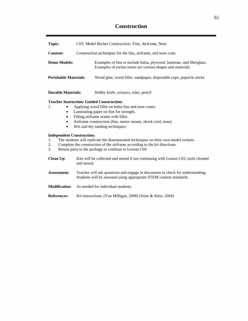
61
Construction
Topic:
C03: Model Rocket Construction: Fins, Airframe, Nose
Content:
Construction techniques for the fins, airframe, and nose cone.
Demo Models:
Examples of fins to include balsa, plywood, laminate, and fiberglass. Examples of rocket noses are various shapes and materials.
Perishable Materials:
Wood glue, wood filler, sandpaper, disposable cups, popsicle sticks
Durable Materials:
Hobby knife, scissors, ruler, pencil
Teacher Instruction/ Guided Construction: 1. Applying wood filler on balsa fins and nose cones. Laminating paper on fins for strength. Filling airframe seams with filler. Airframe construction (fins, motor mount, shock cord, nose) Wet and dry sanding techniques.
Independent Construction: 1. The students will replicate the demonstrated techniques on their own model rockets. 2. Complete the construction of the airframe according to the kit directions. 3. Return parts to the package or continue to Lesson C04
Clean Up: Kits will be collected and stored if not continuing with Lesson C03, tools cleaned
and stored.
Assessment: Teacher will ask questions and engage in discussion to check for understanding. Students will be assessed using appropriate STEM content standards.
Modification: As needed for individual students.
References: Kit instructions, (Van Milligan, 2008) (Stine & Stine, 2004)

62
Construction
Topic:
C04: Model Rocket Construction: Payload Bays
Content:
Adding a payload bay to a model rocket.
Demo Models:
Examples of completed payload bays
Perishable Materials:
Model rocket kits, glue, tape, airframe tubes similar to kit.
Durable Materials:
Hobby knife, scissors, ruler, pencil, airframe cutting jig
Teacher Instruction/ Guided Construction: 1. The teacher will demonstrate how to scratch build a payload bay. Instruction includes: Designing a payload bay
Cutting airframes Bulkheads Vent holes for altimeter
Independent Construction: 1. to build their own bays. 2. Return parts to the package or store on model rocket stand.
Clean Up:
Clean and store materials, pick up trash.
Assessment: Teacher will ask questions and engage in discussion to check for understanding. Students will be assessed using appropriate STEM content standards.
Modification:
As needed for individual students.
References: (Van Milligan, 2008) (Canepa, 2005) (Stine & Stine, 2004)
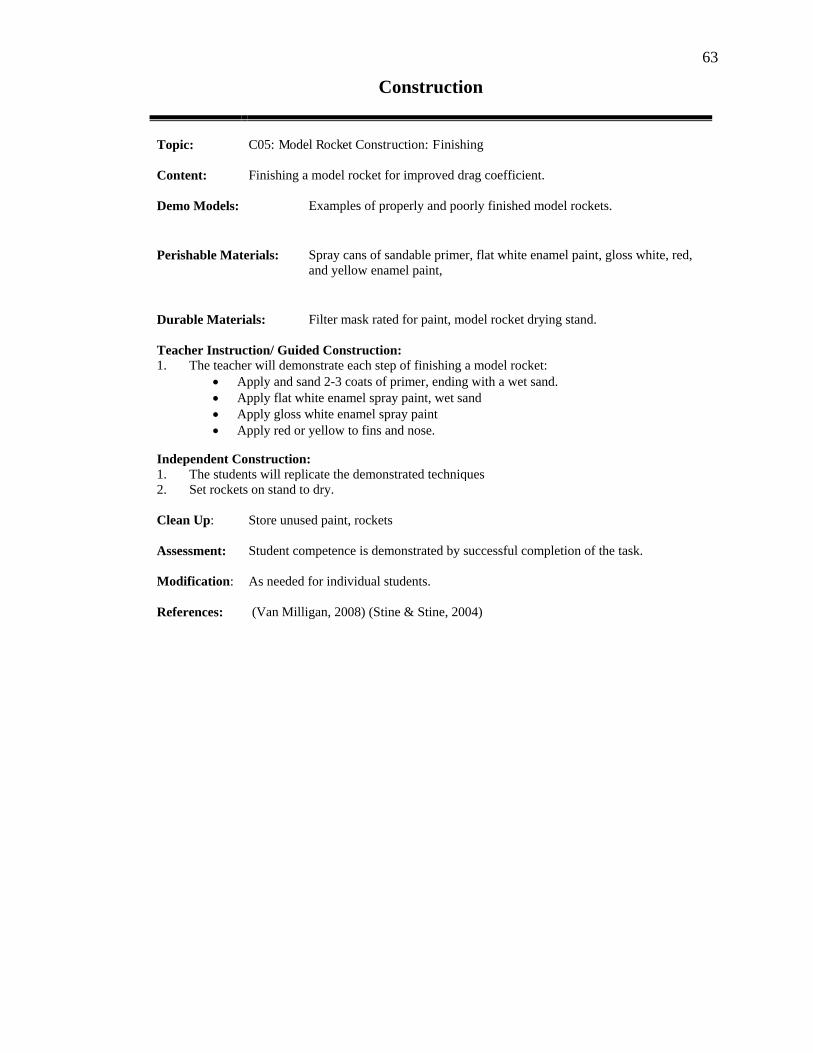
63
Construction Topic:
C05: Model Rocket Construction: Finishing
Content:
Finishing a model rocket for improved drag coefficient.
Demo Models:
Examples of properly and poorly finished model rockets.
Perishable Materials: Spray cans of sandable primer, flat white enamel paint, gloss white, red, and yellow enamel paint,
Durable Materials: Filter mask rated for paint, model rocket drying stand.
Teacher Instruction/ Guided Construction: 1. The teacher will demonstrate each step of finishing a model rocket: Apply and sand 2-3 coats of primer, ending with a wet sand. Apply flat white enamel spray paint, wet sand Apply gloss white enamel spray paint Apply red or yellow to fins and nose.
Independent Construction: 1. The students will replicate the demonstrated techniques 2. Set rockets on stand to dry.
Clean Up:
Store unused paint, rockets
Assessment:
Student competence is demonstrated by successful completion of the task.
Modification:
As needed for individual students.
References: (Van Milligan, 2008) (Stine & Stine, 2004)

64
Construction Topic:
C06: Recovery Systems
Content:
The students will construct parachutes and streamers for their model rocket.
Demo Models:
A variety of completed streamers and parachutes.
Perishable Materials:
Plastic, Mylar, carpet thread, page hole reinforcing rings, launch lugs
Durable Materials:
Hobby knife, scissors, ruler, pencil
Teacher Instruction/ Guided Construction: 1. Give a hands –on demonstration of various forms of parachutes and streamers. Examples should include parachutes made of plastic, Mylar, and rip-stop nylon,
parachutes with and without spill holes, and streamers made out of crepe paper, Dura Lar, and Mylar. Discuss the pros and cons of each design. Demonstrate how to construct a parachute and a streamer. If time is available, conduct a launch that demonstrates each recovery system.
Independent Construction: 1. Students will each construct a parachute and a streamer for their model rocket.
Clean Up:
Tools and materials will be stored away be the students.
Assessment
Student competence is demonstrated by successful completion of the task.
Modification:
As needed for individual students.
References: (Van Milligan, 2008) (Stine & Stine, 2004)

65
Investigation and Discovery The most exciting time for the students is when they get to fly their model rockets. It is during these launches that the previous lessons will be reinforced by the investigation and discovery lessons. It is an exciting time for the teacher as well. Students will work independently as they prepare the rockets for launch and to collect valuable flight data. The knowledge gained on the field during launch day will enrich the post-flight activities as the students analyze and decipher the collected data in the classroom. There are three distinct phases of each investigation and discovery lesson:
Preflight Activities - occur the day before launch day. o teacher briefing on lesson goals. o selection and preparation of rockets, o inspection of all equipment o equipment training o launch day weather report from the meteorologists.
Launch Day - o transport equipment and rockets to launch site o set up equipment and conduct launches o record data o recover equipment and rockets to class room o conduct quick post-flight debriefing if possible
Post-Flight Activities - o analyze and discuss collected data o assessment of student understanding

66
Investigation & Discovery Topic:
ID01: Data Collecting Instruments
Content:
A introduction to instruments used to collect data on wind, humidity, temperature, air pressure, flight times, distances and altitude.
Statement of Investigation: Data on the weather conditions and of the rocket‟s flight can be collected with the proper instruments.
Equipment: Sling psychrometer (humidity), anemometer (wind speed), barometer (air pressure),
thermometer (air temperature), stopwatch (time), and Estes Altitrak or similar device (altitude), Flight Data Logs
Teacher Instruction/ Guided Construction: 1. Demonstrate the operation of each instrument. 2. Demonstrate how to record data on the Flight Log.
Guided Practice: 1. Divide the students into enough group to rotate through each instrument as they
gain hands-on experience.
Discovery: 1. Collect and record data and analyze results.
Independent Practice: Students will collect data as assigned during rocket launches. Assessment: Student competence is demonstrated by successful completion of the task.
Modification: As needed for individual students.
References: Instrument manuals (Exline, Arlene & Levine, 2008)

67
Investigation & Discovery
Topic:
ID02: Investigating Parachutes
Content:
Parachute design
Statement of Investigation: Students launch rockets with parachutes of different sizes, shapes, and spill holes and collect data for analysis.
Equipment: A single rocket or rockets of equal design, engine and weight, a variety of parachutes
of different diameters and spill holes.
Preflight Procedures: 1. Lesson LD02, The Model Rocket 2. Preparation of Equipment 3. Safety Briefing
Guided Practice: 1. Set up Equipment 2. Conduct activity and collect data 3. Recover equipment
Discovery: 1. Collect and record data: Descent times from apogee for each parachute. Observe for oscillation, spinning, and deployment. Record times and observation on the Flight Log.
2. Group analysis of results: Class will discuss and compare data and determine the best parachute design among those that were deployed.
Independent Practice: Students will collect data as assigned during rocket launches. Assessment: Student competence is demonstrated by successful completion of the task.
Teacher will ask questions and engage in discussion to check for understanding. Students will be assessed using appropriate STEM content standards.
Modification: As needed for individual students.
References: (Van Milligan, 2008) (Stine & Stine, 2004)

68
Investigation & Discovery Topic:
ID03: Calculating Apogee
Content: Students learn how to use the Pythagorean Theorem, marker streamers, and electronic altimeters to determine the rocket‟s altitude at apogee.
Statement of Investigation: Rocket altitude can be determined by various methods.
Equipment: Rocket with payload section, launch equipment, two Estes Altitraks, measuring
wheel, stopwatches, marker streamers, and electronic altimeter.
Preflight Procedures: 1. Assignment of duties 2. Preparation of Equipment:
1. Prepare rocket with motor and recovery system. 2. Make marker streamers as instructed in Appendix I, Marker
Streamers. 3. Install marker streamer over the recovery system and the electronic
altimeter in the payload bay.
3. Safety Briefing
Guided Practice: 1. Set up Equipment Two students are placed with the Altitraks with one student placed
halfway between the other tracker and the launch pad. Timers are assigned to time the drop of the marker streamers. The electronic altimeter is activated by the pad crew.
2. Launch rocket with all 3 apogee calculation methods deployed. 3. Recover equipment
Discovery: 1. Collect and record data: All data is recorded on the Flight Log 2. Group analysis of results
1. Students compare the results of the different methods. 2. How close are the 3 methods in apogee calculation? 3.
Assessment: Teacher will ask questions and engage in discussion to check for understanding. Students will be assessed using appropriate STEM content standards.
Modification: As needed for individual students.
References: (Nolte, 1994) (Cannon, 1970) Appendix I, Marker Streamers
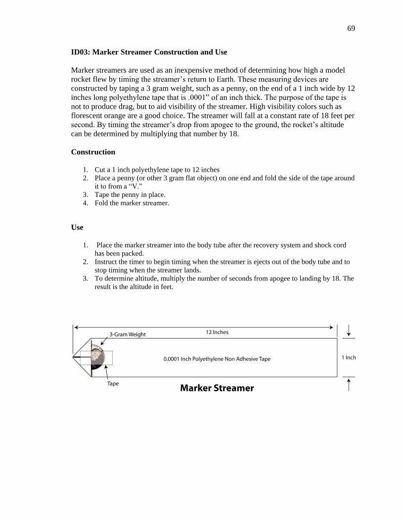
69
ID03: Marker Streamer Construction and Use
Marker streamers are used as an inexpensive method of determining how high a model rocket flew by timing the streamer‟s return to Earth. These measuring devices are constructed by taping a 3 gram weight, such as a penny, on the end of a 1 inch wide by 12 inches long polyethylene tape that is .0001” of an inch thick. The purpose of the tape is not to produce drag, but to aid visibility of the streamer. High visibility colors such as florescent orange are a good choice. The streamer will fall at a constant rate of 18 feet per second. By timing the streamer‟s drop from apogee to the ground, the rocket‟s altitude can be determined by multiplying that number by 18. Construction
1. Cut a 1 inch polyethylene tape to 12 inches 2. Place a penny (or other 3 gram flat object) on one end and fold the side of the tape around
it to from a “V.” 3. Tape the penny in place. 4. Fold the marker streamer.
Use
1. Place the marker streamer into the body tube after the recovery system and shock cord has been packed.
2. Instruct the timer to begin timing when the streamer is ejects out of the body tube and to stop timing when the streamer lands.
3. To determine altitude, multiply the number of seconds from apogee to landing by 18. The result is the altitude in feet.

70
Investigation & Discovery Topic:
ID04: Adjusting Apogee
Content:
Adjusting the mass of the rocket to change the apogee.
Statement of Investigation: The students will reduce the altitude of a model rocket by 25% using Newton‟s Second Law of Motion as a guide: F = MA.
Equipment: Rocket with payload section, launch equipment, two Estes Altitraks, measuring
wheel, stopwatches, marker streamers, electronic altimeter, clay or lead weights.
Preflight Procedures: 1. Assignment of duties 2. Preparation of Equipment 3. Safety Briefing
Guided Practice: 1. Set up Equipment 2. Launch rocket and determine its apogee. 3. By using F = MA, calculate the additional mass needed to reduce the apogee to
25% lower. 4. Prepare rocket with adjusted mass and launch again. 5. Repeat process until apogee has been reduced by 25% from the first flight.
Discovery: 1. Collect and record data: All data is recorded on the Flight Log 2. Students determine mass adjustment.
Independent Practice: TARC teams will adjust apogees in their own rockets. Assessment: Teacher will ask questions and engage in discussion to check for understanding.
Students will be assessed using appropriate STEM content standards.
Modification: As needed for individual students.
References: (Stine & Stine, 2004) (Nolte, 1994) (Cannon, 1970)

71
Investigation & Discovery Topic:
ID05: Adjusting Descent Rate Using Parachutes & Streamers
Content:
Adjusting descent rate of model rocket by changing drag coefficient.
Statement of Investigation: Students will use different types of streamers to alter the payload section‟s time of descent.
Equipment: Rocket used in Lesson ID04 including added mass, two parachutes two sizes larger
that original parachute without spill holes and two of the largest size with two different sized spillholes.
Preflight Procedures: 1. Assignment of duties 2. Preparation of Equipment: Prepare rocket with recommended parachute. 3. Safety Briefing
Guided Practice: 1. Set up Equipment 2. Launch rocket and determine its apogee. 3. By using knowledge gained by Lessons ID02 and ID09, increase the time of
flight by 25% of first flight. NOTE: If adding 25% more time to time of flight may cause the rocket to leave the recovery area, target a lower percentage.
4. Repeat the process using streamers of different sizes and materials.
Discovery: 1. Collect and record data 2. Students determine adjustment.
Independent Practice: TARC teams will adjust apogees in their own rockets. Assessment: Teacher will ask questions and engage in discussion to check for understanding.
Students will be assessed using appropriate STEM content standards.
Modification: As needed for individual students.
References: (Van Milligan, 2008) (Stine & Stine, 2004)

72
Investigation & Discovery Topic:
ID06: Investigating Average Velocity
Content: Measuring Velocity of model rockets after determining altitude.
Statement of Investigation: Students will determine the average velocity of a model rocket in flight by using the equation v = d/t.
Equipment: Rockets with similar mass and motors, launch equipment, two Estes Altitraks,
measuring wheel, stopwatches, marker streamers, electronic altimeter
Preflight Procedures: 1. Assignment of duties 2. Preparation of Equipment 3. Safety Briefing
Guided Practice: 1. Set up Equipment 2. Launch several rockets. Time flights from launch to apogee and calculate
altitude. 3. Recover equipment
Discovery: 1. Collect and record data: record times and determine altitude. 2. Group analysis of results: Using the formula v=d/t, determine the average
velocity of each rocket. 3. Determine the combined average velocity of all launched rockets.
Independent Practice: TARC students are able to determine the average velocity of their own rockets. Assessment: Student competence is demonstrated by successful completion of the task.
Teacher will ask questions and engage in discussion to check for understanding. Students will be assessed using appropriate STEM content standards.
Modification: As needed for individual students.
References: (Stine & Stine, 2004)

73
Investigation & Discovery Topic:
ID07: Investigating Energy
Content:
Predicting the apogee of a model rocket based on the rocket motor.
Statement of Investigation: The altitude of a model rocket can be predicted based on the mass of the rocket and the energy of the motor.
Equipment: Rockets with similar mass and motors, launch equipment, two Estes Altitraks,
measuring wheel, stopwatches, marker streamers, electronic altimeter
Preflight Procedures: 1. Assignment of duties 2. Preparation of Equipment 3. Safety Briefing Guided Practice: 1. Set up Equipment 2. Launch rocket with an A motor and determine its altitude. 3. Lead class in a discussion about the predicted altitude of the rocket with a B
motor. Record predictions. 4. Launch rocket with a B motor and determine its altitude. 3. Recover equipment Discovery: 1. Collect and record data 2. Group analysis of results: How accurate was the prediction verses the actual
altitude? Where there any unbalanced forces that could have effected the results?
Assessment: Student competence is demonstrated by successful completion of the task. Teacher will ask questions and engage in discussion to check for understanding. Students will be assessed using appropriate STEM content standards.
Modification: As needed for individual students.
References: (Stine & Stine, 2004)

74
Investigation & Discovery
Topic:
ID08: Investigating Nose Drag Co efficiency
Content:
The investigation and discovery of model rocket noses.
Statement of Investigation: Students will determine drag co efficiency of various nose shapes.
Equipment: Model rocket, noses that fit the rocket of the following shapes: Elliptical,
parabolic, conical, ogive. Hemisphere, launch and data equipment.
Preflight Procedures: 1. Assignment of duties 2. Preparation of Equipment 3. Safety Briefing
Guided Practice: 1. Set up Equipment 2. Students will fly the model rocket with a different nose for each
flight under the following conditions: Each flight uses the same motor Each flight uses a different nose
3. Recover equipment Discovery: 1. Collect and record data:
The altitude of each flight is recorded either from an electronic altimeter or an Estes Altitrak. The results are entered on the Flight Log.
2. Group analysis of results: Students will determine which cones flew the highest with minimum pitch and yaw.
Independent Practice: TARC students will determine the best nose shape for their rocket. Assessment: Student competence is demonstrated by successful completion of the task.
Teacher will ask questions and engage in discussion to check for understanding. Students will be assessed using appropriate STEM content standards.
Modification: As needed for individual students.
References: (Van Milligan, 2008) (Stine & Stine, 2004)

75
Investigation & Discovery Topic:
ID09: Investigating Streamers
Content:
The investigation and discovery of streamer recovery for model rockets.
Statement of Investigation: Students will discover the drag coefficients of streamers constructed of different material and of different lengths.
Equipment: 1. A low power model rocket with ample space for streamers.
2. The following streamers::one each 1”, 2”, and 4” x 10” made of Mylar or polyethylene and one each A 1”, 2”, and 4” x 10” made of crepe paper
Preflight Procedures: 1. Assignment of duties 2. Preparation of Equipment 3. Safety Briefing
Guided Practice: 1. Set up equipment 2. Conduct activity and collect data as described below. 3. Break down equipment
Discovery: 1. Collect and record data: Students will collect and record the times from apogee to landing (to measure descent
rate) and the distance from the launch pad (to measure drift) Information will be recorded on a graph showing descent rate and drift.
2. Group analysis of results The class will determine the best streamer for the test rocket; that being the streamer with the highest drag yet still durable enough to give consistent results.
Independent Practice: TARC student will adjust the recovery of their rocket. Assessment: Student competence is demonstrated by successful completion of the task.
Teacher will ask questions and engage in discussion to check for understanding. Students will be assessed using appropriate STEM content standards.
Modification: As needed for individual students.
References: (Van Milligan, 2008) (Stine & Stine, 2004)

76
Investigation & Discovery Topic:
ID10: Investigating Weathercocking
Content:
Students study the effects of wind on rocket flight.
Statement of Investigation: The wind is an unbalanced force that affects a rockets trajectory and altitude.
Equipment: For classroom demonstration: model rocket with large fins suspended by the nose
with string, fan with strong and focused current. For field demonstration: model rockets with different types of fins, launch equipment, windy day.
Preflight Procedures: 1. Give a demonstration of weathercocking by placing the model rocket in the fan‟s current. 2. Assignment of duties 3. Preparation of Equipment 4. Safety Briefing
Guided Practice: 1. Set up Equipment 2. Students observe and record effects of weathercocking during rocket flight. 3. Recover equipment
Discovery: 1. Collect and record data 2. Group analysis of results: Classroom discussion of observations. Which fin performed the
best?
Independent Practice: TARC students will select the best fin design for their rocket. Assessment: Student competence is demonstrated by successful completion of the task.
Teacher will ask questions and engage in discussion to check for understanding. Students will be assessed using appropriate STEM content standards.
Modification: As needed for individual students.
References: (Van Milligan, 2008) (Stine & Stine, 2004)
77
Investigation & Discovery Topic:
ID11: Entering and Analyzing Flight Data in Rocksim
Content:
Students will begin designing their TARC rocket
Statement of Investigation: Rocksim flight simulations are more accurate with proper data.
Equipment:
Copy of Rocksim, computer, model rocket with Rocksim file, launch equipment.
Preflight Procedures: 1. Assignment of duties 2. Preparation of Equipment 3. Safety Briefing
Guided Practice: 1. Set up Equipment 2. Launch rockets and collect data on flight and weather. 3. Recover equipment
Discovery: 1. Collect and record data 2. Group analysis of results: Enter data into Rocksim and run simulations. 3. Compare the results of the simulation with the actual flight.
Independent Practice: TARC students will be able to enter data into Rocksim and analyze the results. Assessment: Student competence is demonstrated by successful completion of the task.
Teacher will ask questions and engage in discussion to check for understanding. Students will be assessed using appropriate STEM content standards.
Modification: As needed for individual students.
References: Rocksim Manual, (Van Milligan, 2008)

78
Investigation & Discovery Topic:
ID12: Determining the Center of Pressure
Content:
Calculating CP using Rocksim, the cardboard cutout method, and the Barrowman method.
Statement of Investigation: The center of pressure can be determined with several methods.
Equipment: Model rocket as an example, caliper and ruler for measurements, cardboard, copy of
Rocksim on a computer Barrowman equation found in the appendix of the Handbook of Model Rocketry.
Procedures: 1. Review lesson LD05, Rocket Stability, with the class. 2. Give a demonstration of using the cardboard cutout method:
1. Draw an outline of the sample rocket on the piece of cardboard using accurate measurements.
2. Cut out the rocket‟s outline from the cardboard. 3. Balance the cutout on the edge of a ruler to determine the center of pressure. 4. Mark the CP‟s location on the cutout.
3. Give a demonstration of using the Barrowman equation to determine the CP using the same cardboard cutout.
4. Using the same model rocket as the design, point out the location of the CP as determined by Rocksim. Measure and mark the Rocksim CP on the cardboard cutout.
5. Compare the three CP locations from the 3 different methods and discuss the findings with the class.
Guided Practice: 1. Guide the students as they repeat the processes with their own rocket design. Discovery: 1. Collect and record center of pressure results. 2. Group analysis of results
Independent Practice: Students will be able to determine the CP of their own rocket. Assessment: Student competence is demonstrated by successful completion of the task.
Teacher will ask questions and engage in discussion to check for understanding. Students will be assessed using appropriate STEM content standards.
Modification: As needed for individual students.
References: (Stine & Stine, 2004) (Kalk & Wash, 1995)
79
Investigation & Discovery Topic:
D13: Determine the Center of Gravity and Stability of a Rocket
Content:
Determine the center of gravity using a string and tape.
Statement of Investigation: The center of pressure of a model rocket can be determined by balancing the rocket with a string.
Equipment: Model rocket with engine installed, sturdy nylon string at least 8 feet long, masking
tape
Procedures: 1. Review lesson LD05, Rocket Stability, with the class. 2. Taking a model rocket with an installed engine and parachute, tie a string around the
airframe and slide the rocket back and forth until it balances on the string. 3. Explain to the class that the rocket balances at the location of the center of gravity. 4. Mark the location of the center of gravity with a pen. 5. Tape string onto airframe at the center of gravity. 6. In a clear area outdoors or in the gym, rotate the rocket in a circle above head. Tell students
to look for any pitch, which will indicate an unstable rocket. 7. If an unstable rocket is available, repeat the process so that the students may see the
difference.
Guided Practice: 1. Have the students repeat the procedures demonstrated to them during the demonstration. 2. Conduct activity and collect data 3. Recover equipment
Discovery: 1. Collect and record data 2. Group analysis of results
Independent Practice: Students will be able to determine the stability of their own rockets. Assessment: Student competence is demonstrated by successful completion of the task.
Teacher will ask questions and engage in discussion to check for understanding. Students will be assessed using appropriate STEM content standards.
Modification: As needed for individual students.
References: (Estes, 1999) (Kalk & Wash, 1995)

80
Investigation & Discovery Topic:
ID14: Basic Meteorology
Content:
Collecting samples of temperature, humidity, pressure, and wind.
Statement of Investigation: Samples of temperature, humidity, air pressure, and wind can be collected using a variety of instruments.
Equipment: Thermometer, anemometer, sling psychrometer, barometer, compass, stop watch,
Meteorologist Log, cloud chart
Procedures: 1. Give a lecture on basic meteorology 2. Demonstrate how to collect and record meteorological data.
Guided Practice: 1. Students practice collecting data with each instrument. 2. Share and discuss collected samples with the class.
Discovery: 1. Collect and record data 2. Group analysis of results
Independent Practice: Students will collect data during rocket launches. Assessment: Assess the accuracy of the data collection.
Teacher will ask questions and engage in discussion to check for understanding. Students will be assessed using appropriate STEM content standards.
Modification: As needed for individual students.
References: (Exline, Arlene & Levine, 2008)

81
CHAPTER 4 TRAINING, ORGANIZATION, AND EQUIPMENT Launch Procedures
Launching model rockets with a middle or high school class requires procedures that maintain control by keeping all students actively involved in a meaningful activity. It also maintains a high level of safety, which is of paramount importance to the teacher. The following procedures meet those needs and are designed for a class of twenty to thirty students.
These launch procedures are loosely based on the actual count procedures used for the Pershing 1a missile operated by the United States Army in Germany. The MGM-31 Pershing was a solid-fueled two-stage medium-range ballistic nuclear missile designed and built by Martin Marietta. The Pershing systems lasted over 30 years from the first test version in 1960 through final elimination in 1991 (The Cold War Museum, 2008). The researcher served for over three years in a United States Army Pershing firing battery from 1981 to 1984 and was assigned as a flight controller on a Combat Alert Site (CAS) in southern Germany. Over a four-month period, the researcher took part in many simulated launches of the missiles on the remote site. The spirit of speed, efficiency, and safety of the Pershing launch procedures were preserved.
The curriculum was developed from two years of experience teaching a 13-week model rocketry elective to middle school students at E.V. Cain Middle School in Auburn, CA. The model rocketry elective is very popular with students and parents. Students take launches very seriously and behavior problems have been rare. This is a very powerful teaching tool.
Figure 3 a Quest Courier

82
Organization Upon completion of the model rocket construction phase, the students must be
given launch assignments and trained in procedures and equipment before conducting the first launch.
The class organization is set up to accommodate a compliment of 29 students.
Table of Suggested Launch Duty Assignments Assignment # of Positions Total Positions FLIGHT CONTROL SECTION 4 Student Flight Director 1 Flight controller 1 Launch control specialist 1 Communications Officer 1 ENGINEERING SECTION 5 Chief Engineer 1 Engineer 4+ SCIENCE SECTION 14 Chief Scientist 1 Meteorologist 3+ Flight Timer 4+ Tracking Station OIC 1 Tracker 2+ Surveyor 2 Observer 2+ SECURITY/RECOVERY SECTION 5 Chief Security 1 Security/Recovery 4+ TOTAL: 29 Note: numbers followed by the + sign are positions that additional students may be assigned to.

83
The educator may assign positions dependent on the size of the class by combining responsibilities in smaller classes or assigning more than the suggested number of timers or security members. If the class is composed of 10 or less students, it is recommended that the educator use a more informal method of conducting launches that meet the requirements of the Model Rocket Safety Code(National Association of Rocketry, 2009).
The assignments are grouped into four sections; flight control, engineering, science, and security/recovery. Each position and a description of the responsibilities are listed followed by recommendations of how to fill the positions.
Figure 4 Organization & Equipment
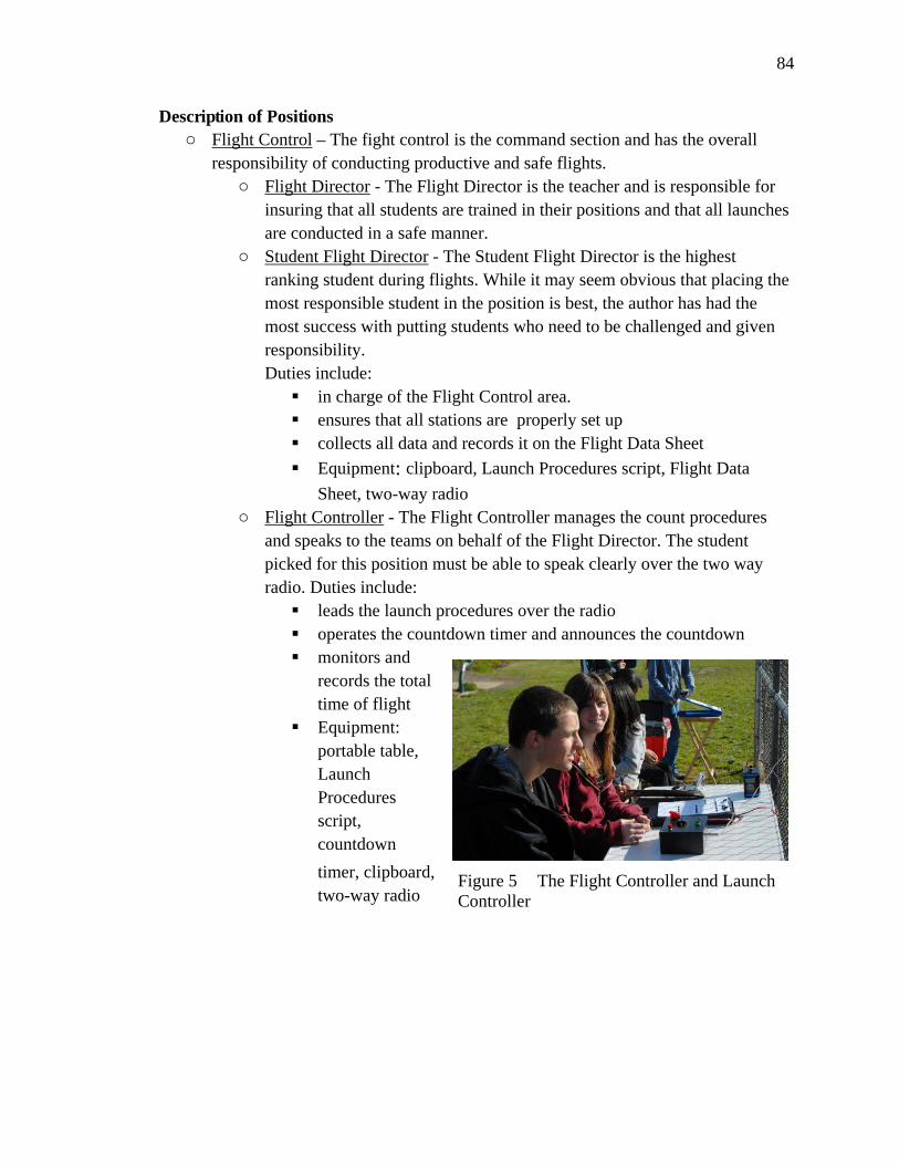
84
Description of Positions o Flight Control – The fight control is the command section and has the overall
responsibility of conducting productive and safe flights. o Flight Director - The Flight Director is the teacher and is responsible for
insuring that all students are trained in their positions and that all launches are conducted in a safe manner.
o Student Flight Director - The Student Flight Director is the highest ranking student during flights. While it may seem obvious that placing the most responsible student in the position is best, the author has had the most success with putting students who need to be challenged and given responsibility. Duties include:
in charge of the Flight Control area. ensures that all stations are properly set up collects all data and records it on the Flight Data Sheet
Equipment: clipboard, Launch Procedures script, Flight Data
Sheet, two-way radio o Flight Controller - The Flight Controller manages the count procedures
and speaks to the teams on behalf of the Flight Director. The student picked for this position must be able to speak clearly over the two way radio. Duties include:
leads the launch procedures over the radio operates the countdown timer and announces the countdown monitors and
records the total time of flight
Equipment: portable table, Launch Procedures script, countdown
timer, clipboard, two-way radio
Figure 5 The Flight Controller and Launch Controller

85
o Launch Controller – The launch controller specialist operates the launch
controller, which launches the rockets. A student good at troubleshooting misfires and malfunctioning equipment. Sits next to the flight controller. Duties include:
ensures that the launch controller is operational and ready for launches
ensures the safety of students by monitoring the location of the launch safety key
operates both switches of the launch controller during launches of teacher-built rockets
operates the safety switch during launches of student rockets trains students on the launch controller Equipment: launch controller
o Communications Officer – The Communications Officer is responsible for the two way radios. The assignment may be combined with another if the class size is small. Duties:
conduct maintenance on the radios on pre-flight days assign radios to the proper personnel Ensure that all radios are accounted for after the launch. Equipment: tool box with radios and spare batteries
Engineering – The engineers prepare rockets for launch using the Pre-Launch
Checklist. On launch day, they set up the launch pad and rockets. o Chief Engineer – The chief engineer ensures that the engineering section
is following proper procedures in a safe manner. Duties:
Follows Pre-Flight Checklist Oversees the setup of the launch pad Communicates with flight control over
the two way radio Controls safety key Equipment: clipboard, Launch
Procedures script, pre-launch checklist, two way radio, fire extinguisher
Figure 6 An engineer prepares a rocket

86
Rocket Engineer – The rocket engineers are responsible for prepping the rockets for flight. There can be as few as one or as many as four students assigned to this position. Duties:
inspect and prep rockets for launch maintain and clean launch equipment set up and break down launch equipment maintain control of prepped rockets provide safety and security on the launch pad ensure that rocket engines are secure Equipment: Ready box, tool box with launch pads and launch controller Science – The science section is the largest section and has the most important job
of collecting the data that will be used in the classroom. o Chief Scientist– The chief scientist is responsible for the accurate
collection of data during rocket launched. Duties: collect data on weather conditions from the meteorologists, times
from the timers, the degrees reported by the tracking station(s), measurements and compass readings from the surveyors, and flight characteristics from the observers.
record data on the Science Data Sheet. Equipment: clipboard, launch procedures script, science data sheet,
two way radio o Meteorologist– The meteorologists obtain weather reports for launch day
and collect real-time data of conditions during launch. At least two students share these duties.
Check online weather sources and brief the class on weather predictions for launch activities
Determine humidity, barometric pressure, temperature, wind speed and direction, cloud conditions, dew point
Equipment: sling psychrometer, barometer, wind speed gauge or anemometer, cloud chart, toolbox for
equipment, clipboard.
Figure 7 A meteorologist operates the sling psychrometer

87
o Flight Timer – The flight timers time whatever part of the flight that the lesson calls for. There should be at least two timers for each time needed, three is better. More than one timed event, such as launch to apogee and apogee to landing, may be recorded on the same flight.
Equipment: one stopwatch for each timer o Tracking Station OIC – The tracking station officer is responsible for
ensuring that trackers are in place for launches and to record and report readings in degrees. This student may also act as an altitude tracker if needed.
Equipment: clipboard, Tracking Station Record Log, two way radio
o Altitude Tracker – The altitude trackers measure the altitude of the rocket in degrees using an Estes AltiTrak or similar device. The trackers are positioned by the surveyors using the measuring wheel.
Equipment – Estes AltiTrak, two way radio if stationed at a distance from the tracking station officer
o Surveyor– The surveyors measure ground distance using a measuring wheel, and determine the direction of rocket landing from launch pad in degrees. They are also responsible for helping the meteorologists determine wind direction.
Measure distance for trackers to stand Determine direction of landing in degrees. Determine distance of landing Determine wind direction. Equipment: measuring wheel, lensatic compass
o Observer– The observers watch the rocket‟s flight and look for roll or pitch. They also assist the recovery team in locating rockets if the team
Figure 8 Two students track a model rocket's flight with the Estes Altitrak

88
loose site of the returning rocket. This responsibility may be assigned to security/recovery if the class is small.
Security & Recovery – Safety is the number one priority and students assigned to this section must be mature and dependable. They are very important in the likely event that the launch field is being shared with other types of classes, such as physical education.
o Chief of Security– The security officer is in charge of the security section and communicates with the control center over the two way radio. Duties:
Create a security perimeter around the launch pad of at least 20 feet
Position security personnel around the perimeter Take note of wind direction and position personnel for rocket
recovery Communicate security status to the control center Ensure that no one enters the perimeter while the pad is hot Secures the rocket at its landing site until the surveyors have
determined distance and direction o Security/Recovery - Members of security/recovery follow the directions of
the security officer and maintain security around the launch pad. They are also responsible for the recovery of the rocket.
Figure 9 View of the Launch Pad from Control Center

89
Assignment Recommendations Care should be taken in assigning students to the duties that they will perform
during the launches. The most challenging positions are the ones that require leadership and management skills. Those positions, the student flight director, chief scientist, chief engineer should be filled by students who have demonstrated leadership qualities. Because of their importance to the success of the launches and data collection obtained by them, these positions should be filled first. Consideration for the remaining positions, in the order of importance, is as follows:
Student Flight Director – This is a position that can really bring out the best in the right student. The best student flight director that the researcher ever has was a student who was disruptive and unmotivated in class until given this assignment. That student not only transformed into a model student, he went on to participate in the Team America Rocketry Challenge and was instrumental in his team‟s success. Some students are just waiting for the opportunity to prove themselves.
Flight Controller - As the student who will be the center of communications during the launch, flight controllers should speak in a loud, clear voice.
Engineers – engineers will carefully follow procedures in the preparation of the rockets for flight. Students who do best in this role are careful and methodical.
Meteorologists – These students will be active collecting data and are using equipment that is expensive and fragile. Students selected as meteorologists should be responsible enough to collect weather data accurately with minimum supervision.
Launch Control Specialist – While this position is not very challenging, it is one of the most rewarding. The launch control specialist gets to press the launch button, making it a much sought after job.
Tracking OIC/ Trackers – The students tracking the rocket flights will be 75 or more meters away from the teacher. Students selected must be responsible enough to work independently.
Security/Tracking – The perfect assignment for high energy students who will get plenty of movement as they follow and recover the rockets.
Flight Timers – These students must be focused in order to gather accurate flight times.
Surveyors – Students assigned to these positions need to be accurate in their measurements and directions. Surveyors do the most walking among the students during the launches.

90
Communications Officer – This position can easily be filled by the flight controller as most of the responsibilities occur during pre-launch procedures. Assign to another student if the class is large and a student is available.
Duty Rotation
Rotation of students is recommended in order to maximize student learning and to maintain interest. The frequency is left to the discretion of the educator. If time permits, the class may be retrained using the procedures outlined in Lesson LD06, Launch Procedures. Another technique is to rotate a portion of the students and have them receive “on the job” training by the students who did not rotate. Much of the learning will occur during the post-flight activities when the collected data is analyzed and discussed. Training
Taking the time to train the students on the launch procedures and how to properly the equipment before the first rocket launch will ensure an efficient and safe launch. Train the students on launch procedures using lesson LD06, Launch Procedures.
Because of the volume of rockets that the students will build and fly, it is recommended that the educator devise some form of identification nomenclature for each rocket. The system that the researcher uses has worked well. The first digit is an S, for student or a T, for teacher. The next two digits are the last two numbers of the year. The last two to three digits represent the rocket number for the year. So the 51st rocket build by a student in 2009 would be S0951. The teacher‟s rocket may omit the year and start from the first rocket the teacher built and is written as T055 for the 55st rocket. The numbers are types on small adhesive mailing labels and affixed on the airframe. This is the number that the Chief Engineer will verify with Flight Control prior to launch.

91
Figure E10 Launch Layout Launch Site
A good location to conduct launches in on the school‟s baseball or softball field. Placing the launch pad on the pitcher‟s mound and locating most of the students behind the fencing creates a controllable and safe environment.
Equipment
During launches, many of the students will be responsible for the collection of data to be used for in-class activities. While professional grade equipment may give very accurate results, there is an opportunity for the instructor to add to student knowledge by building some of the equipment in the classroom and by using equipment that require the students to manually collect and interpret data, thus increasing student understanding of the collection process. A student who builds a cup anemometer, counts the number of rotations, and multiplies that number with the diameter of the cup assembly to determine wind velocity will have a much greater understanding of the process than the student who simply reads the wind speed from an electronic device. Design and Engineering Equipment The recommended setup for the teaching of Rocksim software is to have a copy of Rocksim and a computer for each student. As of this writing, Apogee offers an education
92
discount on the software available on their website. Since most middle and high schools now possess a computer lab, it is assumed that the software would be installed there. The teacher will also need built examples of model rockets to use as demonstration models. Constructing the models prior to the lessons helps the teacher to better understand the work required. Construction Equipment and Material Durable equipment will last for many years if properly maintained. Rulers – Used for measuring parts for cutting and gluing.
Hobby Knives – These knives dull quickly in the hands of inexperienced builders, so a supply of replacement blades is a must. Cutting Mats – help to extend the life of the hobby knife blade not to mention the class tables. Pencils – to mark fin and launch lug locations. Scissors – are handy for several of the construction steps. Consumable Supplies will need to be restocked after their use. Rocket Kits – The easiest choice for the educator is to purchase a complete model rocket kit for each student. It is also the most expensive. Another method is to purchase the model rocket parts in bulk and give the students the added challenge of building from scratch. Making the Paradigm 5 found in The Handbook of Model Rocketry is simple and inexpensive. Students may also design their own model rocket on Rocksim, print the templates and parts lists, and build it. Glue – Wood glue is perfect for small rockets. Students who will build a mid-powered rocket to compete in the Team America Rocketry Challenge will need to become familiar with ca glue and epoxy as well. Tape – Masking tape is used to mask off areas of the model rocket for multi color paint schemes. The tape is also used to friction fit rocket motors into the motor mount. Paint – The most efficient method of painting the model rockets is to use the enamel spray cans found in all hardware stores. Painting should be done outdoors for enough away from the class so that the fumes don‟t make their way back in. With generous funding, a program could set up airbrush stations and use water-based paint.
Launch Equipment
Launch Pad – There are several commercially made launch pads that will work. The challenge with most of them is that they sit very low the ground, making it difficult for the students to set up the rockets and for the instructor to inspect the work. A simple pad for three rockets can be made with a saw horse or custom built with PVC pipe and connectors.

93
Electronic Launcher – As with launch pads, commercial launchers will work fine. Most are 6 volt systems that have only a 15 foot electrical cord. For maximum safety, a 12 volt system with 50 foot cords will move the students to a distance that makes visual tracking of the flight much easier. A custom launch controller made of Radio Shack parts that allow the preparation of three rockets at a time is recommended. Such a system will allow all three rockets to be launched simultaneously or in sequence. This will shorten the launch times and provide more time for post flight lessons. Electronic Model Rocket Launcher Construction Plans and Tips by Tony Wayne offer several electronic launcher plans for the classroom and is available from Apogee Components.
Two-Way Radios - A very important feature of the launch procedures is communication. Two-way radios allow the students to conduct a smooth launch while spread over 5625 square meters or more. The radios also allow the teacher get give instruction. The researcher has given a portion of a altitude calculation lesson by standing at the launch pad and pointing out the parts of the triangle formed by the rocket‟s flight over the radio to the class spread out over the field. Inexpensive radios can be found on eBay and on sale at department and sporting goods stores. Another source is to obtain the school‟s old radios when they
Figure 11 a PVC launch pad for 3 rockets made by the author. The rockets from left to right are the Apogee Avion, the Estes Loadstar, and a scratch built Paradigm 5.

94
purchase new ones. For two-way radios, the required range of operation is very small. Another dimension that the radios give is an additional “wow” factor to the activity. The students love using the radios. It is recommended that the radios be distributed and returned at the launch site for control purposes. The students should be instructed that all transmissions are in the public domain and are under the control of the Federal Communications Commission.
Fire Extinguisher– As an added safety precaution, a portable fire extinguisher is recommended.
Countdown Timer – a simple kitchen battery operated timer can be used by the flight controller for the countdown.
Portable Tables – for the Control Center and the Meteorologists.
Data Collection Equipment Sling Psychrometer – The sling psychrometer is used by the meteorologists to
determine the relative humidity during the launch. The data can also be used to determine the dew point. The Taylor 1330PJ Sling Psychrometer is a good inexpensive choice. It also uses a nontoxic red liquid rather than mercury, making it a safer choice for student use.
Thermometer – While the meteorologists can use the dry thermometer on the sling psychrometer to record the temperature, an inexpensive thermometer can provide a more accurate reading of the launch site‟s temperature.
Wind Meter/Anemometer – The teacher has several options for determining wind speed.
o Cup anemometers rotate in the wind and can be used to determine the wind velocity in feet per minute. While commercial versions are available, the students can make their own cup anemometers using paper cups and straws. The plans for a student built cup anemometer and instructions on its use are located in the appendix.
o Electronic hand held anemometers such as the La Crosse EA-3010 Anemometer. This model uses a small fan to determine wind speed, temperature, and wind chill, but there are others who utilize a small cup anemometer for reading.
o Wind socks, a common sight at small airfields, is another effective methods for measuring wind speed and direction. A 15 knot (17mph) wind will fully extend the windsock. A 3 knot (3.5mph) breeze is required to cause the windsock to orient itself according to the wind. Wind direction is the opposite of the direction in which the windsock is pointing. The Federal Aviation Administration (FAA) specifications for windsock use are located in the appendix.
o Windmill anemometers are also available for use for wind speed and direction readings. This type is expensive and is usually affixed

95
permanently to the tops of buildings. Portable versions are available as well, but are too fragile for student use.
Barometer – A barometer is used to measure atmospheric pressure. A hand held barometer is recommended. These types of barometers have a manual adjustment ring to adjust for the altitude of the launch site.
Altimeter - Knowing the altitude of the launch site in required for accurate calculation of barometric pressure. The least expensive way for determining launch site altitude above sea level is to use Google Earth, or a similar program, to get that information. Hand held altimeters and GPS devices will also provide that information.
Trackers – The typical tracker is a simple pointing device that requires the tracker to follow the rocket‟s flight and measure the apogee in degrees. That data, combined with the measured distance of the tracker from the launch pad will be used during post flight lessons to determine the highest altitude of the rocket‟s flight. An example of one of these devices is the Estes Altitrak, which is a plastic tracker that requires the tracker to depress the trigger during flight and release it at apogee. This action locks a weighted arm into position and the degrees can be read through a small opening in the arm. Plans for a triple-track tracker is provided in the appendix of the Handbook of Model Rocketry. Simple, but accurate trackers can be made out of typical classroom materials.
Marker Streamer – A simple method of determining maximum altitude of a model rocket is the use of a marker streamer. Details on constructing and using marker streamers are in the appendix.
Lensatic Compass – Also known as a military compass, this inexpensive compass is used to determine magnetic North on the launch site, and to determine the direction of rocket landing from the launch pad and of the tracking stations.
Measuring Wheel – Measuring wheels operate by rolling the wheel on the ground from one spot to another and the distance is either mechanically or electronically displayed. A wheel that measures in meters is preferred. Electronic versions measure in meters as well as feet.
Digital Scale – a digital kitchen scale large enough to weigh the rockets, motors, and parts in grams. Weigh rocket parts to enter an accurate mass weight in Rocksim. The engineers will use the scale to weigh the rocket before and after flight.

96
Appendix 1: Countdown Procedures
Long Count: Speaker Says Flight Director Flight Control, commence launch procedures. Flight Control Attention all launch personnel; the Flight Director has given permission to
begin countdown preparations. All teams report a GO – NO GO on launch commencements:
Note: teams are to report GO if their equipment is functional and they are in position. Report a NO GO if there are any problems with equipment or personnel. If a team reports a NO GO, Recorder is to continue with the team check, then hold countdown preparations until NO GO team reports a GO. Flight Control Tracking? Tracking Station OIC
Go Flight (or NO GO Flight, then state reason for NO GO)
Flight Control Security? Security OIC Go Flight (or NO GO Flight, then state reason for NO GO) Flight Control Engineers? Engineer OIC Go Flight (or NO GO Flight, then state reason for NO GO) Flight Control Weather? Meteorologist Go Flight (or NO GO Flight, then state reason for NO GO) Flight Control Science? Science OIC Go Flight (or NO GO Flight, then state reason for NO GO) Flight Control (If all report GO) All Teams report GO, commence launch procedures. All teams prepare for launch in accordance with special instructions. Quick Count Pad OIC Flight Control,
Verify rocket number _______ (rocket SN) on Pad # ____. (Note: The Pad OIC will verify all remaining rockets in the same manner.)
Flight Control Rocket number ________ is verified for launch. (repeat #) Meteorologist Flight Control, Wind Speed is at ___ miles per hour. Conditions are GO
for launch. Flight Control Understand. Wind speed is at ___ miles per hour; GO for launch. Engineer OIC Flight Control, Pad OIC requests permission to clear pad. Pad checklist is
complete with the exception of removal of the Launch Key on Rocket number _________
Flight Director Understand. Pad OIC stand by. Flight Control; give a final status check of teams.
Flight Control Understand. All teams report a GO – NO GO on launch commencements. Flight Control Tracking Tracking Station OIC
GO Flight (or NO GO Flight, then state reason for NO GO)
Flight Control Security Security OIC Go Flight (or NO GO Flight, then state reason for NO GO) Flight Control Engineers Engineer OIC Go Flight (or NO GO Flight, then state reason for NO GO) Flight Control Weather Meteorologist Go Flight (or NO GO Flight, then state reason for NO GO) Flight Control Science

97
Science OIC Go Flight (or NO GO Flight, then state reason for NO GO) Flight Control All teams stand by for launch. Flight Director Pad OIC, you have permission to remove Launch Key and clear pad. Engineer OIC (After crew has left pad and entered the Engineer Bunker) Pad is clear. The Pad OIC brings the Launch Key to Flight Control and delivers it to the Launch Control Specialist. The Launch Control Specialist will conduct a hot test on the launch system. Launch Control Specialist
(Without a radio to Recorder) Hot Test is complete, pad (1,2,3) is hot.
Flight Control Pad is hot. Flight Director Flight Control, begin 15 second countdown on my mark ….mark. Flight Control (on radio) 10, 9, 8, 7, 6, 5, 4, 3, 2, 1, Ignition! Flight Control (on radio if liftoff successful) Liftoff! Security OIC (on radio when rocket touches down) Touchdown ! DATA/ ROCKET RECOVERY Data Collection : Student Flight OIC collects and records flight data on the Flight Data Sheet. Transmission of data over the two way radios should be reserved for students who are at a distance from fight control, such as the tracking station. Nearby stations may pass data directly to the Student Flight OIC. Flight Control All stations report data. Flight Control Tracking Tracking Station OIC
Tracking Station Alpha reports ____ degrees. Tracking Station Bravo reports ____ degrees. Tracking Station Charlie reports ____ degrees.
Flight Control Science OIC report to Flight Control with data. Science Officer Science OIC will collect data from timers, observers, meteorologists, and
surveyors and turn in the completed Science Data sheet to the Student Flight Director.

98
APPENDIX 2: ENGINEER CHECKLIST
ROCKET SERIAL # __________________ BUILDER: _________________________________________________________
PRE-FLIGHT SAFETY CHECK GO NO
GO
All glue and paint on model is completely dry Model is complete and all parts are present Nose cone fits properly and is not tight Nose cone is securely attached to the airframe Shock cord is secure Airframe is straight with no bends or warps Fins are present, securely attached and properly aligned Fins are undamaged Launch lug is securely attached to the airframe Motor mount is secure and operational ROCKET IS READY FOR FLIGHT!
PRE-FLIGHT PREPARATION
ROCKET WEIGHT EMPTY: _______ grams Wadding installed Recovery system installed Rocket motor nomenclature: ___________ Rocket motor undamaged Rocket motor installed Igniter and igniter plug installed Payload description:
_______________________________________________ Payload installed ROCKET WEIGHT LOADED: ________ grams
POST-FLIGHT INSPECTION Rocket successfully recovered Rocket nose, airframe, and fins are intact and undamaged Recovery system is reusable ROCKET POST-FLIGHT WEIGHT : ________ grams
(Including engine casing & recovery system)

99
APPENDIX 3: FLIGHT LOG
Rocket Name: _____________________________________
Serial # _____________________
Builder:___________________________________________
LAUNCH INFORMATION FLIGHT DATA
Date: Liftoff Recovery Launch Time: Successful: Recovery System Deployment Location: Misfire Stage 1 Launch Pad Elevation: Stage 1: Before Apogee: Stage 2: At Apogee:
ROCKET DATA Pitch & Roll During Descent:
Fin Design: Thrust Phase Partial Deployment: Fin # No Pitch/Roll: Failed to Deploy: Engine Pitched: Stage 2 Stage 1: Rolled: Before Apogee: Stage 2: Tumbled: At Apogee: Weathercock: During Descent: Recovery System Coast Phase Partial Deployment: Stage 1: Straight Trajectory: Failed to Deploy: Parachute - Weathercock: Diameter: Tumbled: Recovery System Performance Spill Hole Diameter: Stage 1 Streamer - ALTITUDE Stable Descent:
Size: Tracking Station Oscillation: Material: Track. 1 Distance from pad: Spinning: Stage 2: Track.2 Distance from pad: Stage 2 Parachute - Track.3 Distance from pad: Stable Descent: Diameter: Tracker 1 Degrees: Oscillation: Spill Hole Diameter: Tracker 2 Degrees: Spinning: Streamer - Tracker 3 Degrees: Size: Landing Material: Marker Streamer Soft: Timer 1: Hard: Mass Timer 2: Crash: Empty: Distance from Pad: Loaded: Electronic Altimeter Direction from Pad: Post: Reading: FLIGHT TIMES Post Flight Inspection
METEOROLOGY To Apogee Damage Temperature: Timer 1: Nose: Humidity: Timer 2: Airframe: Barometer: Apogee to Landing Fins: Wind Speed: Timer 1: Shock Cord: Wind Direction: Timer 2: Recovery System: Conditions: Total Time of Flight Can be reflown? Cloud Type: Timer 1: Timer 2:

100
APPENDIX 4: METEOROLOGIST WORKSHEET Date: _______________ Time of Collection: ________________ Air Temperature (oF): o Wind Speed Range KPH Dry Bulb Temperature: o Wind Direction: Wet Bulb Temperature: o Barometric Pressure: In Hg Dry Bulb Temp. – Wet Bulb Temp. =
o Visibility: o
Relative Humidity: o Cloud Type: Dew Point: Dry Bulb
o
Sling Psychrometer Worksheet Difference between Dry and Wet Bulbs in degrees
1 o 2 o 3 o 4 o 5 o 6 o 7 o 8 o 9 o 10 o 11 o 12 o 13 o 14 o 15 o 32 90 79 70 60 50 40 31 22 13 4 34 91 81 72 62 53 44 35 26 18 9 1 36 91 52 74 65 56 48 39 31 22 14 6 38 92 83 75 67 59 51 42 35 27 19 11 4 40 92 84 76 68 61 53 46 38 31 23 16 9 2 42 92 85 77 70 62 55 48 41 34 28 21 14 7 44 93 85 78 71 64 57 50 44 37 31 24 18 12 5 46 93 86 79 72 65 59 52 46 40 34 28 22 16 10 4 48 93 86 80 73 67 61 54 48 42 36 31 25 19 14 11 50 94 87 81 74 68 62 56 50 45 39 33 28 22 17 12 52 94 87 81 75 69 63 58 52 47 41 36 31 25 20 15 54 94 88 82 76 70 65 59 54 49 43 38 33 28 23 20 56 94 88 83 77 71 66 61 56 51 45 40 36 31 26 22 58 94 89 83 78 71 67 62 57 52 47 42 38 33 29 24 60 94 89 84 78 73 68 63 58 54 49 44 40 35 34 27 62 95 89 84 79 74 69 64 60 55 51 46 42 38 34 29 64 95 90 84 79 74 70 65 60 56 51 47 43 38 34 30 66 95 90 85 80 75 71 66 61 57 53 48 44 40 36 32 68 95 90 85 80 75 71 67 62 58 54 50 46 42 38 34 70 95 90 86 81 77 72 68 64 59 55 51 48 44 40 36 72 95 91 86 82 77 73 69 65 61 57 53 49 45 42 38 74 95 91 86 82 78 74 69 65 61 58 54 50 47 43 39 76 96 91 87 82 78 74 70 66 62 59 55 51 48 44 41 78 96 91 87 83 79 75 71 67 63 60 56 53 49 46 43 80 96 91 87 83 79 75 72 68 64 61 57 54 50 47 44 82 96 92 88 84 80 76 72 69 65 61 58 55 51 48 45 84 96 92 88 84 80 76 73 69 66 62 59 56 52 49 46 86 96 92 88 84 81 77 73 70 66 63 60 57 53 50 47 88 96 92 88 85 81 77 74 70 67 64 61 57 54 51 48 90 96 92 89 85 81 78 74 71 68 65 61 58 55 52 49 92 96 92 89 85 82 78 75 72 68 65 62 59 56 53 50 94 96 92 89 85 82 79 75 72 69 66 63 60 57 54 51
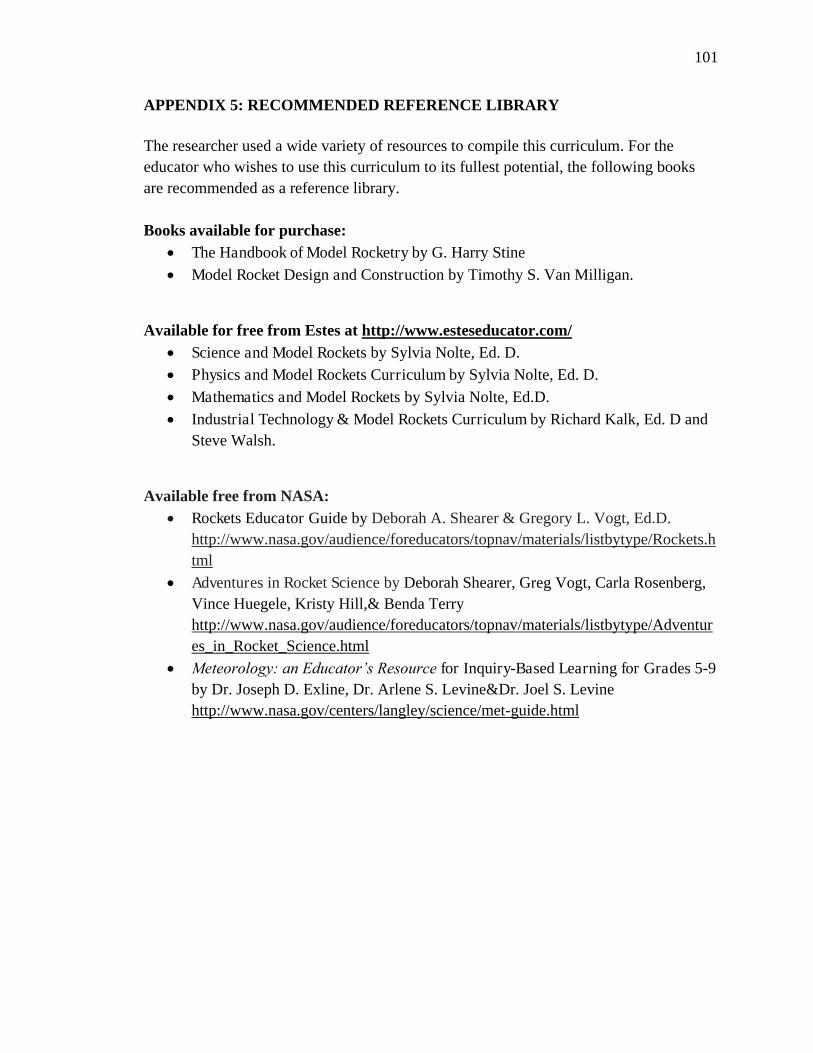
101
APPENDIX 5: RECOMMENDED REFERENCE LIBRARY The researcher used a wide variety of resources to compile this curriculum. For the educator who wishes to use this curriculum to its fullest potential, the following books are recommended as a reference library. Books available for purchase:
The Handbook of Model Rocketry by G. Harry Stine Model Rocket Design and Construction by Timothy S. Van Milligan.
Available for free from Estes at http://www.esteseducator.com/
Science and Model Rockets by Sylvia Nolte, Ed. D. Physics and Model Rockets Curriculum by Sylvia Nolte, Ed. D. Mathematics and Model Rockets by Sylvia Nolte, Ed.D.
Industrial Technology & Model Rockets Curriculum by Richard Kalk, Ed. D and Steve Walsh.
Available free from NASA:
Rockets Educator Guide by Deborah A. Shearer & Gregory L. Vogt, Ed.D. http://www.nasa.gov/audience/foreducators/topnav/materials/listbytype/Rockets.html
Adventures in Rocket Science by Deborah Shearer, Greg Vogt, Carla Rosenberg, Vince Huegele, Kristy Hill,& Benda Terry http://www.nasa.gov/audience/foreducators/topnav/materials/listbytype/Adventures_in_Rocket_Science.html
Meteorology: an Educator’s Resource for Inquiry-Based Learning for Grades 5-9 by Dr. Joseph D. Exline, Dr. Arlene S. Levine&Dr. Joel S. Levine http://www.nasa.gov/centers/langley/science/met-guide.html

102
References 4-H. (2009).4-H. Retrieved August 6, 2009, from 4-H: http://4-h.org/
Abernathy, T. V., & Vinyard, R. N. (2001). Academic competitions in science: What are
the rewards for students? The Clearing House, 74(5), 269-276.
Aerospace Industries Association. (2008). Aerospace Industries Association. Retrieved
May 18, 2008, from http://www.aia-aerospace.org/
Aerospace Industries Association. (2009). Team America rocketry challenge. Retrieved
September 12, 2009, from http://www.rocketcontest.org/
Aerospace Industries Association. (2009). Team America rocketry challenge: Contest
background. Retrieved September 12, 2009, from
http://www.rocketcontest.org/tarc_background.cfm
Aerospace Industries Association. (2009). Team America rocketry challenge: Results and
standings. Retrieved September 12, 2009, from
http://www.rocketcontest.org/standings.cfm
Air Force Association. (2008). Air force association. Retrieved May 17, 2008, from
http://www.afa.org/aef/default.asp?pm=asg
American Institute of Aeronautics and Astronautics. (2008). Students and educators.
Retrieved May 17, 2008, from http://www.aiaa.org/content.cfm?pageid=5
American Institute of Aeronautics and Astronautics. (2009, May 13). Building and
retaining the aerospace workforce. Reston, VA: Author.

103
American Society for Engineering Education. (2009). K-12. Retrieved October 3, 2009,
from http://www.asee.org/k12/index.cfm
American Society for Engineering Education. (2007, January 1). National content
standards: K12 engineering/engineering technology. Retrieved August 9, 2009,
from http://www.asee.org/
Answers Corporation. (2009). Centuri. Retrieved August 16, 2009, from
http://www.answers.com/topic/centuri-1
Banks, M. A., & Van Milligan, T. S. (1998). Advanced model rocketry. Waukesha, WI:
Kalmback Books.
Barber, T. (2006). Team America rocketry challenge. Official Journal of the National
Association of Rocketry, September/October, 5-12.
Beach, T. (2007, January 1). An interview with Vern and Gleda Estes the golden days of
model rocketry part 1.Official Journal of the National Association of Rocketry,
January/February,1-7.
California State Board of Education. (1999). Mathematics content standards for
California public schools, kindergarten through grade twelve. Sacramento:
California Department of Education.
California State Board of Education. (2003). Science content standards for California
public schools, kindergarten through grade twelve. Sacramento: California
Department of Education.
California State Board of Education. (2009). California state board of education.
Retrieved July 16, 2009, from http://www.cde.ca.gov/be/

104
Canepa, M. (2005). Modern high-power rocketry 2. Victoria, BC, Canada: Trafford
Publishing.
Cannon, R. L. (1970). Elementary mathematics of model rocket flight. Penrose, CO:
Centuri Corporation.
Cannon, R. L. (1998). Newton's laws of motion and model rocketry. Penrose, CO: Estes
Industries.
Cannon, R. L., & Banks, M. A. (1987). The rocket book. New York: Prentice Hall.
Civil Air Patrol. (2004, March 15). CAP model rocketry program regulation 50-20.
Maxwell AFB, AL: Author.
Civil Air Patrol. (2009). Civil air patrol. Retrieved August 6, 2009, from
http://www.gocivilairpatrol.com/html/index.htm
Coalition for Science After School. (2008, January 1). After school programs: At the stem
of learning. Afterschool Alliance. Retrieved August 5, 2009, from
http://www.afterschoolalliance.org/issue_26_STEM.cfm
The Cold War Museum. (2008). The Pershing missile system and the cold war. Retrieved
October 9, 2009, from http://www.coldwar.org/Articles/50s/pershing_missiles.asp
Curriculum Development and Supplemental Materials Commission. (2005). Mathematics
framework for California public schools, kindergarten through grade twelve.
Sacramento: California Department of Education.
Estes Industries. (1999).How Estes model rocketry benefits you and your students.
Retrieved September 15, 2009, from
http://www.esteseducator.com/content/benefits.php

105
Estes Industries. (2009). Estes educator. Retrieved August 30, 2009, from
http://www.esteseducator.com/
Estes, V. (1961, July 1).Model rocketry vs. amateur rocketry safety survey report.Model
Rocket News, 1(2),1.
Estes, V. (1961). Model rocketry versus amateur rocketry safety survey report. Model
Rocket News, 1(3),3-4.
Estes, V. (1999).Technical note tn-1 model rocket engines. In V. Estes, The classic
collection: Model rocketry. Penrose, CO: Estes Industries.
Estes, V. (1999).Technical report tr-1, rocket stability. InV. Estes,The classic collection:
Model rocketry. Penrose, CO: Estes Industries.
Estes, V. (1999).Technical report tr-1, rocket stability. In V. Estes, The classic collection:
Model rocketry. Penrose, CO: Estes Industries.
Estes, V. (1999).Technical report tr-1, rocket stability. In V. Estes, The classic collection:
Model rocketry. Penrose, CO: Estes Industries.
Estes, V. (1999).Technical report tr-2, multi-staging. In V. Estes, The classic collection:
Model rocketry. Penrose, CO: Estes Industries.
Estes, V. (1999).The classic collection: Model rocketry. Penrose, CO: Estes Industries.
Exline, J. D.,Levine, A. S., & Levine, J. S. (2008). Meteorology: An educator’s resource
for inquiry-based learning for grades 5-9. Hampton, VA: Langley Research
Center.
Hickam, H. H. (1998). Rocket boys. New York: Dell Publishing.

106
Holloway, J. H. (2002). Extracurricular activities and student motivation.Educational
Leadership, 60(1), 80-81.
Horst, K. (2004).The Physics Teacher, 42, 394-397.
Ignite. (2007). SystemsGo. Retrieved September 22, 2009, from
http://www.igniteeducation.org/index.html
International Technology Education Association. (2003). Advancing excellence in
technological literacy: Student assessment, professional development, and
program standards. Reston, VA: Author.
International Technology Education Association. (2007). Standards for technological
literacy.Reston,VA: ITEA.
International Technology Education Association. (2007). Standards for technological
literacy: Content for the study of technology. Reston, VA: Author.
Kalk, R., & Wash, S. (1995). Industrial technology and model rockets: A curriculum for
grades 6-12. Penrose, CO: Estes Industries.
Mandell, G. K., Caporaso, G. J., & Bengan, W. P. (1973). Topics in advance model
rocketry.Cambridge, MA: MIT Press.
Marshall Space Flight Center. (2002, May 9). NASA's Marshall center to help rocket-
building Texas students get their project off the ground. Retrieved September 22,
2009, from http://www.msfc.nasa.gov/news/news/releases/2002/02-119.html
National Aeronautics and Space Administration. (2005, December 9). Welcome to the
beginner's guide to model rockets. Retrieved October 10, 2009, from
http://exploration.grc.nasa.gov/education/rocket/

107
National Aeronautics and Space Administration. (2009, August 14). NASA. Retrieved
August 15, 2009, from http://www.nasa.gov/home/index.html
National Aeronautics and Space Administration. (2009, June 10). Student launch
initiative. Retrieved September 22, 2009, from
http://www.nasa.gov/offices/education/programs/descriptions/Student_Launch_In
itiative.html
National Association of Rocketry. (2008, July 1). Team America rocketry challenge.
NAR Member Handbook,55.
National Association of Rocketry. (2009, March 1). Model rocket safety code. Retrieved
October 10, 2009, from http://www.nar.org/NARmrsc.html
National Association of Rocketry. (2009). The NAR 4H partnership. Retrieved August 6,
2009, from http://www.nar.org/4-H.html
National Commission on Excellence in Education (A Report to the Nation & the United
States Secretary of Education). (1983, April 1). A nation at risk: the imperative
for educational reform. Washington, DC: U.S. Government Printing Office.
National Committee on Science Education Standards & Assessment. (1996). National
science education standards. National Research Council. Washington, DC:
National Academy Press.
The National Council of Teachers of Mathematics.(1996). Executive summary principles
and standards for school mathematics. Retrieved from
http://www.nctm.org/uploadedFiles/Math_Standards/12752_exec_pssm.pdf

108
National Council of Teachers of Mathematics.Commission on Standards for School
Mathematics. (1989). Curriculum and evaluation standards for school
mathematics. Reston, VA: National Council for Teachers of Mathematics.
Nielsen, L. B. (1997). Blast off! Rocketry for elementary and middle school students (S.
Haenel, Ed.). Westport, CT: Libraries Unlimited.
Nolte, S. (1992). Physics and model rockets: A curriculum for grades 8,9,10, & 11. In T.
Brach, T. VanMilligan, & A. Grimm(Eds.), Estes educator. Penrose, CO: Centuri
Corporation.
Nolte, S. (1994).Mathematics and model rockets: A curriculum for grades 5-12. Penrose,
CO: Estes Industries.
Nolte, S., & Stoops, N. (1992).Science and model rockets: A curriculum for grades
5,6,7,8. Penrose, CO: Estes Industries.
Partnership for Public Service, & Institute for the Study of Public Policy Implementation.
(2009). The best places to work in the federal government: National aeronautics
and space administration. Retrieved August 15, 2009, from
http://data.bestplacestowork.org/bptw/detail/NN00
Robertson, W. C. P. D. (2002).Force and motion. Arlington, VA: NTSA Press.
Rockets for Schools. (2008). Rockets for schools: About. Retrieved August 9, 2009, from
http://www.rockets4schools.org/about.html
Saltrick, D. F., & Kubota, A. M. (1970). Aerospace education and model rocketry: An
educator's guide for grades four through ten. Penrose, CO: Estes Industries.
Science Olympiad Inc. (2008). Retrieved August 14, 2009, from http://soinc.org/

109
Shearer, D. A., & Vogt, G. L. (2008).Rockets: Educator's guide with activities in science,
technology, engineering, and mathematics. Houston, TX: National Aeronautics
and Space Administration.
Shearer, D. A., & Vogt, G. L. (2008).Rockets. Washington, DC: National Aeronautics
and Space Administration. Retrieved August 5, 2009, from
http://www.nasa.gov/audience/foreducators/topnav/materials/listbytype/Rockets.h
tml
Shearer, D., Vogt, G., Rosenberg, C., Huegele, V., Hill, K., & Terry, B.
(2007).Adventures in rocket science. Huntsville, AL: National Aeronautics and
Space Center.
Sneider, C. I. (1989). Experimenting with model rockets. Berkeley, CA: Lawrence Hall of
Science.
Stine, G. H., & Stine, B. (2004). Handbook of model rocketry. Hoboken, NJ: John Wiley
& Sons.
Thompson, R. (2008, July 24). Students learn science, math through Starbase Kelly.
Retrieved September 22, 2009, from
http://www.lackland.af.mil/news/story.asp?id=123108076
Van Milligan, T. S. (2008). Model rocket design and construction. Colorado Springs,
CO: Apogee Components, Inc.
Wayne, T. (1996). Electronic model rocket launcher construction plans and tips. Cañon
City, CA: Apogee Components.


Issac NewtonSir Isaac Newton was an English physicist,
mathematician, astronomer, natural philosopher, and alchemist.
In 1666, he witnessed an apple fall from its tree and he began to ponder why it fell down.
This led to his Three Laws of Motion.
Presenter
Presentation Notes
Sir Isaac Newton was an English physicist, mathematician, astronomer, natural philosopher, and alchemist. In 1666, he witnessed an apple fall from its tree and he began to ponder why it fell down. This led to his Three Laws of Motion.

Lex I: Corpus omne perseverare in statu suo quiescendivel movendi uniformiter in directum, nisi quatenus a viribus impressis cogitur statum illum mutare.
FIRST LAW OF MOTIONTHE LAW OF INERTIA
Presenter
Presentation Notes
First Law of Motion: The Law of Inertia Every body perseveres in its state of being at rest or of moving uniformly straight forward, except insofar as it is compelled to change its state by force impressed.

Lex I: Corpus omne perseverare in statu suo quiescendivel movendi uniformiter in directum, nisi quatenus a viribus impressis cogitur statum illum mutare.
FIRST LAW OF MOTIONTHE LAW OF INERTIA
Presenter
Presentation Notes
First Law of Motion: The Law of Inertia Objects at rest will stay at rest (inertia) and objects in motion will stay in motion in a straight line unless acted upon be an unbalanced force.

What Does This Mean?
There is a natural tendency of objects to keep on doing what they're doing. All objects resist changes in their state of motion. In the absence of an unbalanced force, an object in motion will maintain this state of motion.
Presenter
Presentation Notes
There is a natural tendency of objects to keep on doing what they're doing. All objects resist changes in their state of motion. In the absence of an unbalanced force, an object in motion will maintain this state of motion.

Lex II: Mutationem motus proportionalem esse vi motrici impressae, et fieri secundum lineamrectam qua vis illa imprimitur.
SECOND LAW OF MOTIONTHE LAW OF FORCE
Presenter
Presentation Notes
Second Law of Motion: The Law of Force The change of momentum of a body is proportional to the impulse impressed on the body, and happens along the straight line on which that impulse is impressed.
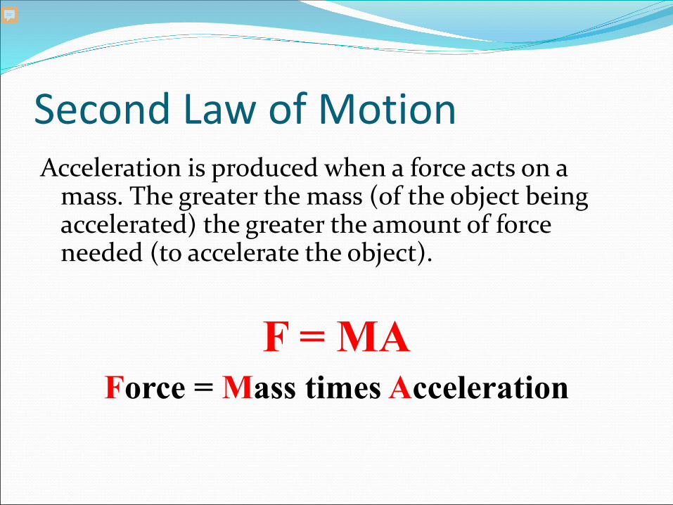
Second Law of MotionAcceleration is produced when a force acts on a
mass. The greater the mass (of the object being accelerated) the greater the amount of force needed (to accelerate the object).
F = MAForce = Mass times Acceleration
Presenter
Presentation Notes
Second Law of Motion: The Law of Force Acceleration is produced when a force acts on a mass. The greater the mass (of the object being accelerated) the greater the amount of force needed (to accelerate the object). F = MA Force = Mass times Acceleration

Second Law in Action A car that weighs 1,000 kg runs out of gas. The
driver pushes the car to a gas station at a speed of 0.05 meters per second. How much force is the driver applying to the car to go that speed?
F = 1,000 kg x 0.05 m/s/sF = 50 Newtons of force
Presenter
Presentation Notes
Second Law in Action A car that weighs 1,000 kg runs out of gas. The driver pushes the car to a gas station at a speed of 0.05 meters per second. How much force is the driver applying to the car to go that speed? F = 1,000 kg x 0.05 m/s/s F = 50 Newtons of force

What the heck is a Newton? The Newton is a unit of force. It is equal to the amount of force required to accelerate
a mass of one kilogram at a rate of one meter per second per second.
Presenter
Presentation Notes
What the heck is a Newton? The Newton is a unit of force. It is equal to the amount of force required to accelerate a mass of one kilogram at a rate of one meter per second per second.

What the heck is a kilogram?
1 kilo = 2.2 pounds
Presenter
Presentation Notes
What the heck is a kilogram? 1 Kilo = 2.2 pounds

You Know The 2nd Law Already! Everyone knows the Second Law: heavier objects
require more force to move the same distance as lighter objects.
We know that we don’t need the same amount of force to lift a feather that what is needed to lift a bowling ball.
Presenter
Presentation Notes
You Know The 2nd Law Already! Everyone knows the Second Law: heavier objects require more force to move the same distance as lighter objects. We know that we don’t need the same amount of force to lift a feather that what is needed to lift a bowling ball.

Lex III: Actioni contrariam semper et æqualem essereactionem: sive corporum duorum actiones in se mutuo semper esse æquales et in partes contrariasdirigi.
THIRD LAW OF MOTIONTHE LAW OF RECIPROCAL ACTIONS
Presenter
Presentation Notes
Third Law of Motion: The Law of Reciprocal Actions For a force there is always an equal and opposite reaction: or the forces of two bodies on each other are always equal and are directed in opposite directions.

Third Law of MotionFor every action, there is an equal and
opposite reaction.
Presenter
Presentation Notes
Third Law of Motion For every action, there is an equal and opposite reaction.
Third Law of Motion

What Does This Mean?
This means that for every force there is a reaction force that is equal in size, but oppositein direction. Whenever an object pushes another object it gets pushed back in the opposite direction with equal force.
Presenter
Presentation Notes
What Does This Mean? This means that for every force there is a reaction force that is equal in size, but opposite in direction. Whenever an object pushes another object it gets pushed back in the opposite direction with equal force.
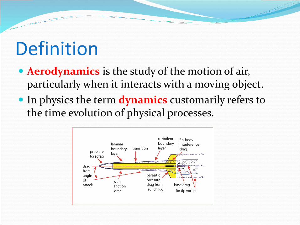
Definition Aerodynamics is the study of the motion of air,
particularly when it interacts with a moving object.
In physics the term dynamics customarily refers to the time evolution of physical processes.

Factors that Affect Aerodynamics
The Object:Shape & Size
The Motion:Velocity &
Inclination to Flow
The Air:Mass, Viscosity, Compressibility

Four Forces of Flight Lift is a force used to stabilize and control the
direction of flight.
Drag is the aerodynamic force parallel to the relative wind.
Weight is the force generated by gravity on the rocket.
Thrust is the force which moves the rocket forward.
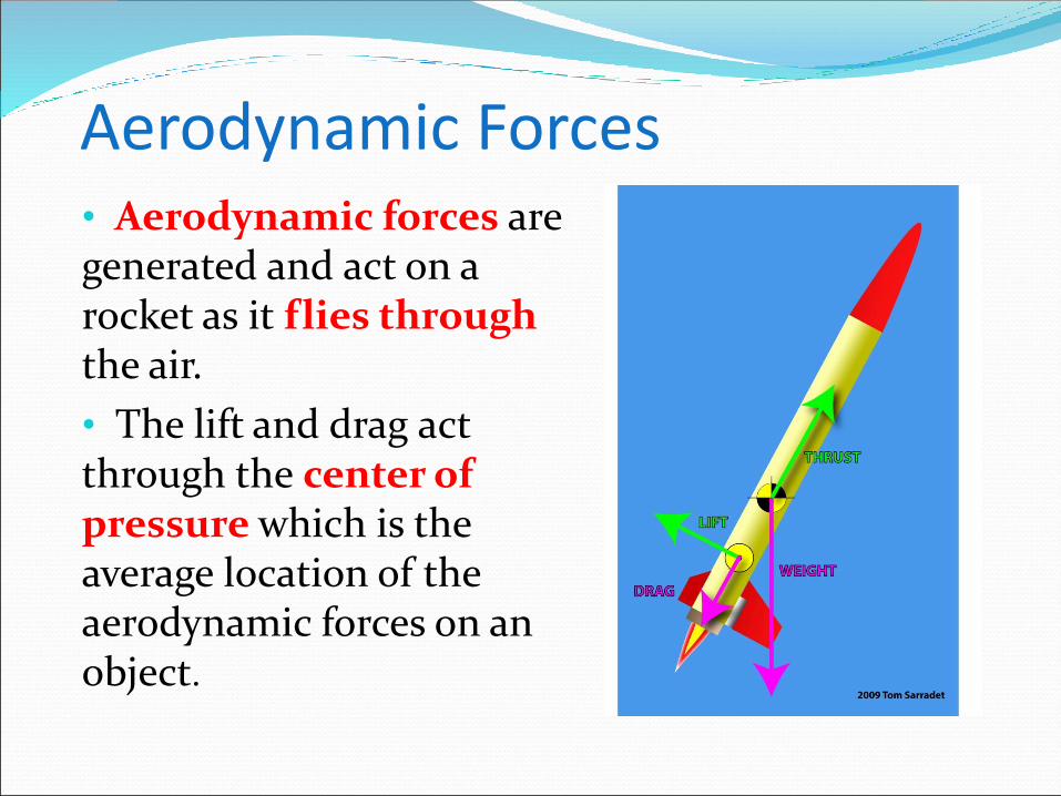
Aerodynamic Forces• Aerodynamic forces are generated and act on a rocket as it flies through the air.
• The lift and drag act through the center of pressure which is the average location of the aerodynamic forces on an object.

Aerodynamic Forces• Aerodynamic forces are mechanical forces. They are generated by the interaction and contact of the rocket with the air.
• For lift and drag to be generated, the rocket must be moving through the air.

Aerodynamic Forces• Lift occurs when a flow of gas (the air) is turned by a solid object (the rocket).
• The flow is turned in one direction, and the lift is generated in the opposite direction.
• For a model rocket, the nose, airframe, and fins can become a source of lift if the rocket’s flight path is at an angle.

Aerodynamic Forces• When a solid body (the rocket) moves through a fluid (gas or liquid), the fluid resists the motion. The rocket is subjected to an aerodynamic force in a direction opposed to the motion which we call drag.

Aerodynamic Forces• Drag is aerodynamic friction, and one of the sources of drag is the skin friction between the molecules of the air and the solid surface of the moving rocket.

Aerodynamic Forces• A boundary layer is the layer of air in the immediate vicinity of the rocket’s surface.
Boundary layers can be laminar (smooth flow) or turbulent (swirling).

Aerodynamic Forces• The point in which a laminar boundary layer becomes turbulent is called the transition.
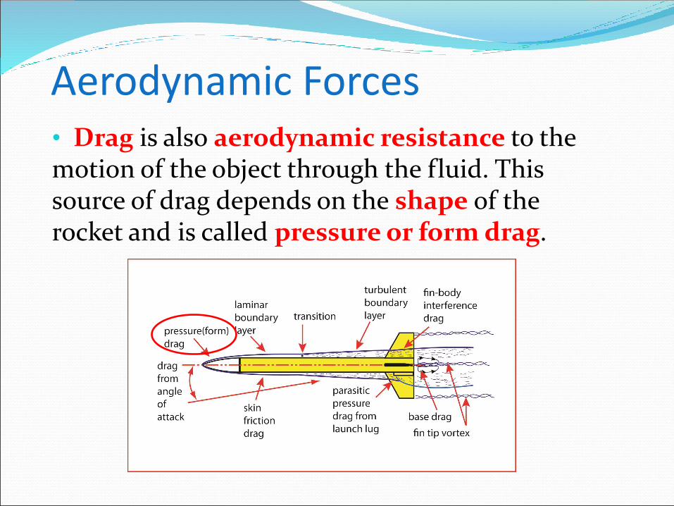
Aerodynamic Forces• Drag is also aerodynamic resistance to the motion of the object through the fluid. This source of drag depends on the shape of the rocket and is called pressure or form drag.
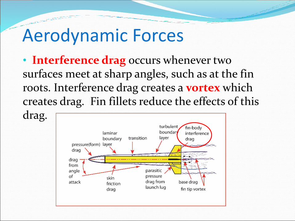
Aerodynamic Forces• Interference drag occurs whenever two surfaces meet at sharp angles, such as at the fin roots. Interference drag creates a vortex which creates drag. Fin fillets reduce the effects of this drag.

Aerodynamic Forces• Air passing by the tips of the fins form a fin tip vortex. Accelerating the air into this vortex causes drag on the fins, and a low pressure area behind them. Tapered fin tips reduce this drag.

Aerodynamic Forces• Parasitic Drag is produced by objects like the launch lug. The launch lug can account for 30% of all drag. Cutting the lug’s leading edge to 45 degrees reduces drag.

• A model rocket’s fin that is square on the edges creates a lot of drag and turbulence.
• If the fin’s leading and trailing edges are sanded in a round shape, called an airfoil, it reduces the drag.
Airfoil Fins

airfoil shape fins creates high pressure behind the fin and pushes it forward, cancelling out most of the pressure drag caused by the fins. This is called pressure recovery.
Airfoil Fins

Weight Weight is the force generated by the gravitational
attraction on the rocket.
The gravitational force is a field force; the source of the force does not have to be in physical contact with the object.
Gravity affects the rocket whether it is stationary or moving (up or down).

Thrust Thrust is the force applied
to the rocket to move it through the air, and through space.
Thrust is generated by the propulsion system of the rocket through the application of Newton's Third Law of Motion.
The direction of the thrust is normally along the longitudinal axis of the rocket through the rocket’s center of gravity.


Rocket Stability During the flight of a model rocket, gusts of wind or
thrust instabilities, can cause the rocket to "wobble", or change its attitude in flight.
Poorly built or designed rockets can also become unstable in flight.
This lesson is about what makes a rocket unstable in flight and what can be done to improve its stability.
Presenter
Presentation Notes
Rocket Stability During the flight of a model rocket, gusts of wind or thrust instabilities, can cause the rocket to "wobble", or change its attitude in flight. Poorly built or designed rockets can also become unstable in flight. This lesson is about what makes a rocket unstable in flight and what can be done to improve its stability.
Translation and Rotation A rocket in flight can move two ways; it can translate,
or change its location from one point to another, and it can rotate, meaning that it can roll around on its axis.
Presenter
Presentation Notes
Translation and Rotation A rocket in flight can move two ways; it can translate, or change its location from one point to another, and it can rotate, meaning that it can roll around on its axis.

How a Rocket Translates

How a Rocket Rotates

Roll Most rockets are symmetric about a line from the tip of
the nose to the center of the nozzle exit. We will call this line the roll axis and motion about this axis is called a rolling motion.
The center of gravity lies along the roll axis.
Presenter
Presentation Notes
Roll Most rockets are symmetric about a line from the tip of the nose to the center of the nozzle exit. We will call this line the roll axis and motion about this axis is called a rolling motion. The center of gravity lies along the roll axis.

Roll

Yaw and Pitch When a rocket wobbles from side to side, this
movement is called a yaw motion. A pitch motion is an up or down movement of the
nose of the rocket.
Presenter
Presentation Notes
Yaw and Pitch When a rocket wobbles from side to side, this movement is called a yaw motion. A pitch motion is an up or down movement of the nose of the rocket.

Pitch

Center of Gravity - CG As a rocket flies through the air, it both translates and
rotates. The rotation occurs about a point called the center of gravity, which is the average location of the weight of the rocket.
Symbol for Center of Gravity
Presenter
Presentation Notes
Center of Gravity – CG As a rocket flies through the air, it both translates and rotates. The rotation occurs about a point called the center of gravity, which is the average location of the weight of the rocket.

Typical Location of CP

How to Determine CG1. Load the motor, recovery system, and payload.
2. Tie a string around the airframe and adjust it until the rocket is horizontally balanced.
3. The location of the string is at the center of gravity.
Presenter
Presentation Notes
How to Determine the Center of Gravity Load the motor, recovery system, and payload. Tie a string around the airframe and adjust it until the rocket is horizontally balanced. The location of the string is the center of gravity.

Center of Pressure - CP The average location of the pressure on the rocket
is called the center of pressure. The parts of the rocket that influences the location of
the center of pressure the most are the fins.
Symbol for Center of Pressure
Presenter
Presentation Notes
Center of Pressure – CP The average location of the pressure on the rocket is called the center of pressure. The parts of the rocket that influences the location of the center of pressure the most are the fins.

Building a Stable Rocket
If the center of gravity is in front of the center of pressure, the rocket will return to its initial flight conditions if it is disturbed. This is called a restoring forcebecause the forces "restore" the rocket to its initial condition and the rocket is said to be stable.
Presenter
Presentation Notes
Building a Stable Rocket If the center of gravity is in front of the center of pressure, the rocket will return to its initial flight conditions if it is disturbed. This is called a restoring force because the forces "restore" the rocket to its initial condition and the rocket is said to be stable.

If the center of gravity and the center of pressure are in the same location, it is called neutral stability.A rocket with neutral stability may make a stable or unstable flight depending on the forces acting on it.
Presenter
Presentation Notes
If the center of gravity and the center of pressure are in the same location, it is called neutral stability. A rocket with neutral stability may make a stable or unstable flight depending on the forces acting on it.

If the center of pressure is in front of the center of gravity, the lift and drag forces maintain their directions but the direction of the torque generated by the forces is reversed. This is called a de-stabilizing force. Any small displacement of the nose generates forces that cause the displacement to increase. Such a flight condition is unstable .
Presenter
Presentation Notes
If the center of pressure is behind the center of gravity, the lift and drag forces maintain their directions but the direction of the torque generated by the forces is reversed. This is called a de-stabilizing force. Any small displacement of the nose generates forces that cause the displacement to increase. Such a flight condition is unstable .

Correcting Unstable FlightTo move the Center of Gravity:
Add or remove weight in the nose cone. Redistribute the Payload Increase or decrease airframe length.
To move the Center of Pressure: Increase or reduce the fin size. Change the shape of the fins. Change the location of the fins. Increase or decrease airframe length/diameter.
Presenter
Presentation Notes
Correcting Unstable Flight To move the Center of Gravity: Add or remove weight in the nose cone. Redistribute the Payload Increase or decrease airframe length. To move the Center of Pressure: Increase or reduce the fin size. Change the shape of the fins. Change the location of the fins. Increase or decrease airframe length/diameter

One Caliber StabilityThe best separation between the center of gravity is for the CP to be at least one body tube diameter in front of the CG. This is called one caliber stability.
Presenter
Presentation Notes
One Caliber Stability The best separation between the center of gravity is for the CP to be at least one body tube diameter in front of the CG. This is called one caliber stability.

Weather Cocking Following the liftoff of a
model rocket, it often turns into the wind. This maneuver is called weather cocking and it is caused by forces, such as a strong wind, pushing on the side of the rocket’s fins.
Presenter
Presentation Notes
Weather Cocking Following the liftoff of a model rocket, it often turns into the wind. This maneuver is called weather cocking and it is caused by forces, such as a strong wind, pushing on the side of the rocket’s fins.


Causes of Weather Cocking Rockets with long airframes experience weather
cocking, especially during the coast phase. Large fins present a larger surface area for the wind. Rockets with a center of gravity that is far in front of
the center of pressure.
Presenter
Presentation Notes
Causes of Weather Cocking Rockets with long airframes experience weather cocking, especially during the coast phase. Large fins present a larger surface area for the wind. Rockets with a center of gravity that is far in front of the center of pressure.

Tube Fins• Using tube fins reduce weather cocking because of the aerodynamic side profile.• Tube fins should be used carefully because these types of rockets tend to be unstable.
Presenter
Presentation Notes
Tube Fins Using tube fins reduce weather cocking because of the aerodynamic side profile. Tube fins should be used carefully because these types of rockets tend to be unstable.