
1 | A guide for specifiers of biomass heating sytems … · 1 | A guide for specifiers of biomass...
28
1 | A guide for specifiers of biomass heating sytems FRONT COVER A guide to specifying biomass heating systems
Transcript of 1 | A guide for specifiers of biomass heating sytems … · 1 | A guide for specifiers of biomass...
1 | A guide for specifiers of biomass heating sytems
FRONT COVER
A guide to specifying biomass heating systems
Partner regions
FOREST stands for “Fostering Efficient long term Supply partnerships”. The project is funded by the European Commission through Intelligent Energy Europe (IEE). For more information about FOREST please see the website at www.forestprogramme.com.
1 | A guide for specifiers of biomass heating sytems
FOREST A guide to specifying biomass systems
Contents
Introduction .............................................................. 1
Biomass heating – a system of systems ............ 2
The project life cycle............................................... 3
Project concept phase ..................................................... 3
Project definition phase ................................................. 4
Implementation phase .................................................... 6
Handover phase ................................................................. 6
Operation phase ................................................................ 6
Biomass combustion systems ............................. 7
Choosing the right fuel ................................................... 9
Boiler sizing ......................................................................... 9
Thermal storage .............................................................. 11
Fuel feeding and handling systems ......................... 12
Storing wood fuel ............................................................ 13
Wood chip storage ..................................................... 13
Pellet storage ..................................................................... 16
Ash and emissions ................................................. 17
Containerised systems .................................................. 18
District heating ....................................................... 19
The boiler ........................................................................... 20
The distribution network ............................................ 20
The consumer circuit .................................................... 20
Appendix ................................................................... 21
Energetic content of fuels ............................................ 21
Energy values for typical fuels .................................. 21
Energy Conversions ....................................................... 21
Regional Annexe (UK) .......................................... 22
Renewable Heat Incentive .......................................... 22
Current UK design guides ............................................ 22
Planning permission ...................................................... 23
Building Regulations ..................................................... 23
Air Quality .......................................................................... 24
Grants and support ........................................................ 24
Standards and assurance ............................................. 24
Woodfuel Suppliers group .......................................... 25
Further guidance ............................................................. 25
Introduction Designing a complete biomass heating system
requires an in depth knowledge of each of the
component systems. Successful biomass
installations depend on careful calculations of heat
load and must take into account a host of site
specific features, so every biomass system is
different. In addition, regulatory requirements and
incentives can vary nationally and regionally so
what works in one case may not work in another.
The aim of this guide is to provide those
considering biomass with enough information to
help them to ask the right questions, and to
persuade those who aren’t to consider the wider
range of possibilities that can make biomass an
effective and cost efficient source of low carbon
heat.
Treco
2
Biomass heating – a system of
systems Implementing a biomass heating solution for a
particular site or client is a potentially complex
procedure. The simplest conventional ‘wet’ heating
systems consist of a boiler (typically oil or gas) and
a distribution system (most often radiators). With
a biomass heating system there are a choice of
boilers and fuels, and although these can often be
integrated with an existing distribution system, a
number of additional components are required for
the system to perform optimally. These will include
fuel storage and handling, additional boilers,
options for thermal storage and a facility for ash
extraction. For this reason we rarely speak of a
biomass boiler in isolation and prefer instead to
refer to a biomass system.
The majority of the components in a biomass
system are interconnected and overall system
performance will depend on providing components
that are compatible and suited to the heat
requirement of the site. It is not uncommon for the
responsibility for different systems to lie with more
than one provider, and under these circumstances
there is a greater risk of problems arising.
Where sufficient expertise is available, one option
is to engage a single provider who can provide a
‘turnkey’ solution, taking responsibility for all
aspects of design and installation. Additionally
Energy Service Companies or ESCOs can undertake
the operation and maintenance of the system under
a heat supply contract. Such providers are a major
feature of advanced biomass markets and provide
an effective means of managing the risk associated
with large or complex projects. For more
information on common partnering arrangements
within the biomass sector please the associated
FOREST guide ‘Partnerships for Success’1.
In a less developed market there may be fewer
experts with knowledge of the whole system and
ESCOs may be harder to find, so another approach
is required which has much in common with
‘Systems Engineering’. This approach treats the
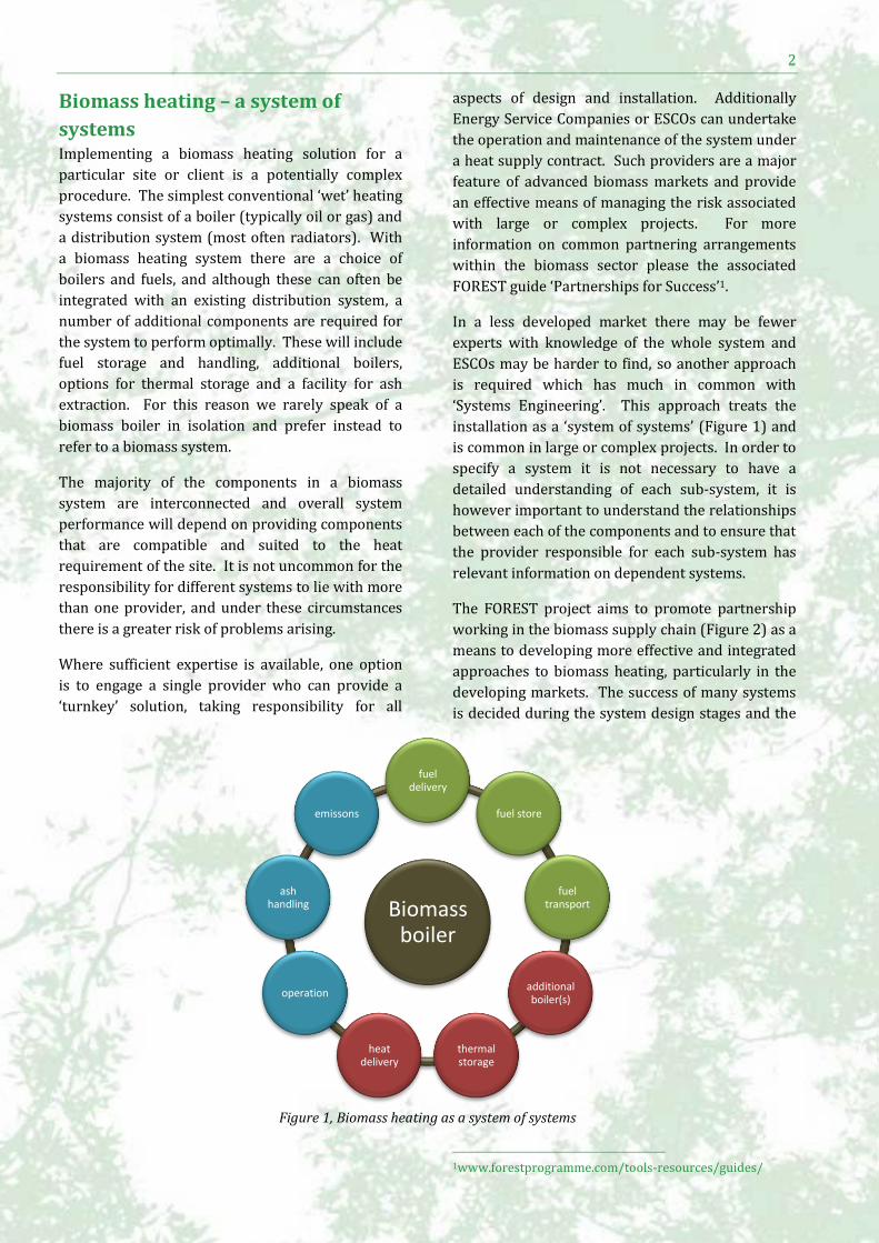
installation as a ‘system of systems’ (Figure 1) and
is common in large or complex projects. In order to
specify a system it is not necessary to have a
detailed understanding of each sub-system, it is
however important to understand the relationships
between each of the components and to ensure that
the provider responsible for each sub-system has
relevant information on dependent systems.
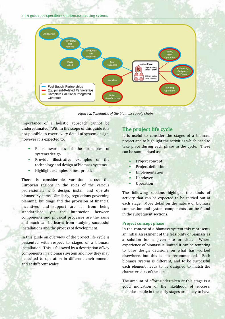
The FOREST project aims to promote partnership
working in the biomass supply chain (Figure 2) as a
means to developing more effective and integrated
approaches to biomass heating, particularly in the
developing markets. The success of many systems
is decided during the system design stages and the
1www.forestprogramme.com/tools-resources/guides/
Biomass boiler
fuel delivery
fuel store
fuel transport
additional boiler(s)
thermal storage
heat delivery
operation
ash handling
emissons
Figure 1, Biomass heating as a system of systems
3 | A guide for specifiers of biomass heating sytems
importance of a holistic approach cannot be
underestimated. Within the scope of this guide it is
not possible to cover every detail of system design,
however it is expected to:
Raise awareness of the principles of
systems design
Provide illustrative examples of the
technology and design of biomass systems
Highlight examples of best practice
There is considerable variation across the
European regions in the roles of the various
professionals who design, install and operate
biomass systems. Similarly, regulations governing
planning, buildings and the provision of financial
incentives and support are far from being
standardised, yet the interaction between
components and physical processes are the same
and much can be learnt from studying successful
installations and the process of development.
In this guide an overview of the project life cycle is
presented with respect to stages of a biomass
installation. This is followed by a description of key
components in a biomass system and how they may
be suited to operation in different environments
and at different scales.
The project life cycle It is useful to consider the stages of a biomass
project and to highlight the activities which need to
take place during each phase in the cycle. These
can be summarised as:
Project concept
Project definition
Implementation
Handover
Operation
The following sections highlight the kinds of
activity that can be expected to be carried out at
each stage. More detail on the nature of biomass
combustion and system components can be found
in the subsequent sections.
Project concept phase
In the context of a biomass system this represents
an initial assessment of the feasibility of biomass as
a solution for a given site or sites. Where
experience of biomass is limited it can be tempting
to base design decisions on what has worked
elsewhere, but this is not recommended. Each
biomass system is different, and to be successful
each element needs to be designed to match the
characteristics of the site.
The amount of effort undertaken at this stage is a
good indication of the likelihood of success;
mistakes made in the early stages are likely to have
Figure 2, Schematic of the biomass supply chain
4
considerable cost implications later so it is worth
taking time to consider the options carefully.
To avoid excessive costs in the early stages this
process can be divided into two stages; a pre-
feasibility stage where inappropriate sites are
filtered out as early as possible, and a more detailed
feasibility study which aims to quantify some of the
key variables to provide a better test of suitability
(Table 1).
If answers to these questions are unclear or
unknown, professional guidance should be sought.
At the end of this phase the aim should be to make a
decision on whether biomass is a viable heating
solution for the site.
Project definition phase
During the project definition the practical technical
and financial details of the system will be further
developed. Earlier work undertaken in the
feasibility stages should provide the basis for a
more informed dialogue with specialist providers.
Key design decisions including the boiler capacity
and type of fuel will need to be taken as these affect
all other aspects of the system and will need to be
made on a clear understanding of the quantity of
heat and the pattern of demand on the site.
Identifying issues that could affect the
implementation or operation of the system in the
early phases can save time and money later and
while technical work will often be carried out by
expert biomass system designers, it can be hard for
an outsider to consider the full range of activities
that take place on or near the site. For example if
there are dates or times where fuel deliveries
cannot be made, or there areas which are sensitive
to noise or vehicle movements, these could affect
design decisions. It can therefore be useful at this
stage to consult with project stakeholders, who can
provide useful feedback to specifying clients and
system designers. A stakeholder could be anyone
affected by the decision to install biomass; this
could include site managers, maintenance staff, and
building occupants. Individuals and businesses
neighbouring the site may also be consulted as they
can be affected, for instance by fuel deliveries,
which can involve additional vehicle movements or
noise.
Good system design is often arrived at through an
iterative process, with successive designs being
trialled with stakeholders until the requirements of
the building, and the people around it, can be met.
Competitive tendering can complicate this kind of
dialogue, as consulting with providers could be
seen as offering an unfair advantage. Only in cases
where the system specifier is experienced, should
providers be offered a detailed design on which to
tender.
However where there is less experience of biomass
or the site is complicated, it can be beneficial to
tender in stages, based on a detailed description of
the requirements at the site. The aim is to allow the
technical experts to provide a range of solutions,
and selecting the best to go forward to the next
stage. This allows for a wider range of solutions to
be considered and increases the chance of finding
the one that is most suitable for the site.
By the end of this phase the specifying client will
have clear picture of the appropriate technical
solution and the financial viability of the system
proposed.
5 | A guide for specifiers of biomass heating sytems
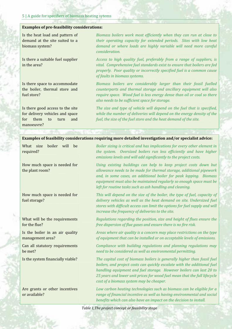
Examples of pre-feasibility considerations:
Is the heat load and pattern of
demand at the site suited to a
biomass system?
Biomass boilers work most efficiently when they can run at close to
their operating capacity for extended periods. Sites with low heat
demand or where loads are highly variable will need more careful
consideration.
Is there a suitable fuel supplier
in the area?
Access to high quality fuel, preferably from a range of suppliers, is
vital. Comprehensive fuel standards exist to ensure that boilers are fed
properly. Poor quality or incorrectly specified fuel is a common cause
of faults in biomass systems.
Is there space to accommodate
the boiler, thermal store and
fuel store?
Biomass boilers are considerably larger than their fossil fuelled
counterparts and thermal storage and ancillary equipment will also
require space. Wood fuel is less energy dense than oil or coal so there
also needs to be sufficient space for storage.
Is there good access to the site
for delivery vehicles and space
for them to turn and
manoeuvre?
The size and type of vehicle will depend on the fuel that is specified,
while the number of deliveries will depend on the energy density of the
fuel, the size of the fuel store and the heat demand of the site.
Examples of feasibility considerations requiring more detailed investigation and/or specialist advice:
What size boiler will be
required?
Boiler sizing is critical and has implications for every other element in
the system. Oversized boilers run less efficiently and have higher
emissions levels and will add significantly to the project costs.
How much space is needed for
the plant room?
Using existing buildings can help to keep project costs down but
allowance needs to be made for thermal storage, additional pipework
and, in some cases, an additional boiler for peak lopping. Biomass
equipment must also be maintained regularly so enough space must be
left for routine tasks such as ash handling and cleaning.
How much space is needed for
fuel storage?
This will depend on the size of the boiler, the type of fuel, capacity of
delivery vehicles as well as the heat demand on site. Undersized fuel
stores with difficult access can limit the options for fuel supply and will
increase the frequency of deliveries to the site.
What will be the requirements
for the flue?
Regulations regarding the position, size and height of flues ensure the
free dispersion of flue gases and ensure there is no fire risk.
Is the boiler in an air quality
management area?
Areas where air quality is a concern may place restrictions on the type
of equipment that can be installed or on acceptable levels of emissions.
Can all statutory requirements
be met?
Compliance with building regulations and planning regulations may
need to be considered as well as environmental permitting.
Is the system financially viable? The capital cost of biomass boilers is generally higher than fossil fuel
boilers, and project costs can quickly escalate with the additional fuel
handling equipment and fuel storage. However boilers can last 20 to
25 years and lower unit prices for wood fuel mean that the full lifecycle
cost of a biomass system may be cheaper.
Are grants or other incentives
or available?
Low carbon heating technologies such as biomass can be eligible for a
range of financial incentive as well as having environmental and social
benefits which can also have an impact on the decision to install.
Table 1,The project concept or feasibility stage
6
Implementation phase
During this phase contacts are awarded and works
are carried out. While the design and specification
work may have been done there are a number of
roles that a specifying client may continue to fulfil.
It is important to maintain communication between
the whole range of supply chain providers who are
delivering the project. The interconnection
between components in the biomass system means
that any changes to the specification can have
affects elsewhere. Regular site meetings and close
contact with contractors and stakeholders will
ensure that any modifications to the system design
are considered properly and do not adversely affect
the capability of the system or its stakeholders.
This phase ends with the commissioning of the
boiler.
Handover phase
Once the system is commissioned the system is
handed over to the user or the operator.
Modern biomass systems are clean and efficient,
however the learning curve for new owners can be
steep where there has been no previous experience
of biomass or solid fuels. An important part of the
handover process is to ensure that operators
receive training in all aspects of operation and basic
maintenance such as emptying ash bins, cleaning,
and simple fault finding.
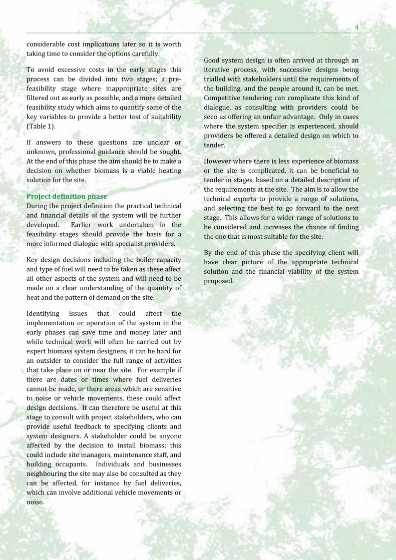
Operation phase
Once the system is left to the client there is
inevitably a period of familiarisation with the
system. Operatives will gain insight into the way
the system responds under different loads or to
slight variations in fuel quality.
A period of monitoring to ensure that the system is
behaving as expected is highly recommended.
Ensuring that the new system integrates as
expected with existing building management
systems and secondary boilers is important and
fuel quality and quantity, heat output and ash
volumes can all be easily monitored.
Monitoring these performance and cost indicators
will also be a good early indicator of any problems
within the system.
Figure 3, 2MW district heating plant
7 | A guide for specifiers of biomass heating sytems
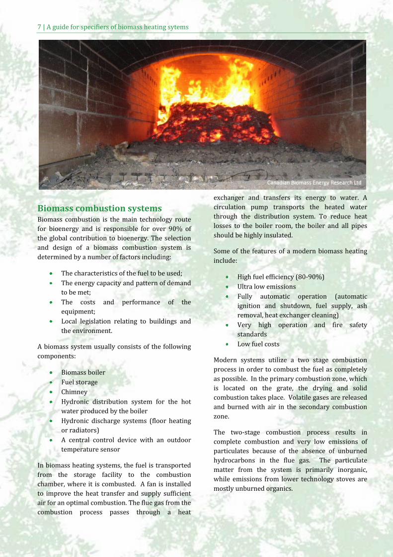
Biomass combustion systems Biomass combustion is the main technology route
for bioenergy and is responsible for over 90% of
the global contribution to bioenergy. The selection
and design of a biomass combustion system is
determined by a number of factors including:
The characteristics of the fuel to be used;
The energy capacity and pattern of demand
to be met;
The costs and performance of the
equipment;
Local legislation relating to buildings and
the environment.
A biomass system usually consists of the following
components:
Biomass boiler
Fuel storage
Chimney
Hydronic distribution system for the hot
water produced by the boiler
Hydronic discharge systems (floor heating
or radiators)
A central control device with an outdoor
temperature sensor
In biomass heating systems, the fuel is transported
from the storage facility to the combustion
chamber, where it is combusted. A fan is installed
to improve the heat transfer and supply sufficient
air for an optimal combustion. The flue gas from the
combustion process passes through a heat
exchanger and transfers its energy to water. A
circulation pump transports the heated water
through the distribution system. To reduce heat
losses to the boiler room, the boiler and all pipes
should be highly insulated.
Some of the features of a modern biomass heating
include:
High fuel efficiency (80-90%)
Ultra low emissions
Fully automatic operation (automatic
ignition and shutdown, fuel supply, ash
removal, heat exchanger cleaning)
Very high operation and fire safety
standards
Low fuel costs
Modern systems utilize a two stage combustion
process in order to combust the fuel as completely
as possible. In the primary combustion zone, which
is located on the grate, the drying and solid
combustion takes place. Volatile gases are released
and burned with air in the secondary combustion
zone.
The two-stage combustion process results in
complete combustion and very low emissions of
particulates because of the absence of unburned
hydrocarbons in the flue gas. The particulate
matter from the system is primarily inorganic,
while emissions from lower technology stoves are
mostly unburned organics.
8
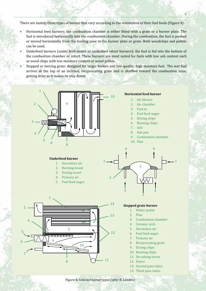
There are mainly three types of burner that vary according to the orientation of their fuel feeds (Figure 4):
Horizontal feed burners: the combustion chamber is either fitted with a grate or a burner plate. The
fuel is introduced horizontally into the combustion chamber. During the combustion, the fuel is pushed
or moved horizontally from the feeding zone to the burner plate or grate. Both woodchips and pellets
can be used.
Underfeed burners (under feed stoker or underfeed retort burners): the fuel is fed into the bottom of
the combustion chamber or retort. These burners are most suited for fuels with low ash content such
as wood chips with low moisture content or wood pellets.
Stepped or moving grate: designed for larger boilers and low quality, high moisture fuel. The wet fuel
arrives at the top of an inclined, reciprocating grate and is shuffled toward the combustion zone,
getting drier as it makes its way down.
1
2
4
5 6
3
7
8
10
9
Horizontal feed burner
1. Air blower
2. Air chamber
3. Fuel in
4. Fuel feed auger
5. Drying chips
6. Burning chips
7. Ash
8. Ash pan
9. Combustion chamber
10. Flue
Underfeed burner
1. Secondary air
2. Burning wood
3. Drying wood
4. Primary air
5. Fuel feed auger
6. Hot gases to boiler
Stepped grate burner
1. Water jacket
2. Flue
3. Combustion chamber
4. Ceramic arch
5. Secondary air
6. Fuel feed auger
7. Primary air
8. Reciprocating grate
9. Drying chips
10. Burning chips
11. De-ashing screw
12. Doors
13. Second pass tubes
14. Third pass tubes
1 1
2
5 4
3
4
6 6
1
2
3
4
7
8
9 10
11
12
13
14
5
6
Figure 4, Selected burner types (after R. Landen)
9 | A guide for specifiers of biomass heating sytems
Top feed burners may also be found in small scale
units developed for pellet combustion. The fuel falls
through a shaft onto a bed of fire consisting of
either a grate or a retort. The feeding system and
the fire bed are separated which makes it an
effective protection against burn-back into the
storage. The ash is removed mechanically by a
dumping grate or manually.
Choosing the right fuel
The key fuel characteristics of biomass fuels are
energy density, moisture content, particle size and
ash properties. Fuels are chosen in order to fulfil
the technological and ecological requirements of
the combustion technology and the most suitable
combination of fuels and technologies can vary
from case to case.
In general low quality fuels demonstrate
inhomogeneous characteristics including high
moisture content, variable particle size, and poor
ash-melting behaviour. Such fuels tend to be used
in large scale systems, while higher quality fuels are
necessary for small scale systems. This is due to
the complexity and robustness of the fuel feeding
systems, the combustion technology and the
management of emissions, all of which require
economies of scale to be economically viable.
The majority of biomass systems burn wood chips
or wood pellets although agricultural residues and
energy crops such as miscanthus and short rotation
coppice based on willow or popular are also used.
While some boilers are designed to take a range of
fuels, others are more particular and regular
switching between fuels is not practical as
combustion settings have to be adjusted to cope
with the different burning characteristics.
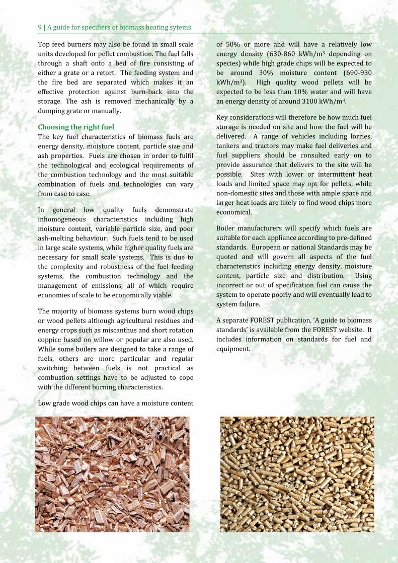
Low grade wood chips can have a moisture content
of 50% or more and will have a relatively low
energy density (630-860 kWh/m3 depending on
species) while high grade chips will be expected to
be around 30% moisture content (690-930
kWh/m3). High quality wood pellets will be
expected to be less than 10% water and will have
an energy density of around 3100 kWh/m3.
Key considerations will therefore be how much fuel
storage is needed on site and how the fuel will be
delivered. A range of vehicles including lorries,
tankers and tractors may make fuel deliveries and
fuel suppliers should be consulted early on to
provide assurance that delivers to the site will be
possible. Sites with lower or intermittent heat
loads and limited space may opt for pellets, while
non-domestic sites and those with ample space and
larger heat loads are likely to find wood chips more
economical.
Boiler manufacturers will specify which fuels are
suitable for each appliance according to pre-defined
standards. European or national Standards may be
quoted and will govern all aspects of the fuel
characteristics including energy density, moisture
content, particle size and distribution. Using
incorrect or out of specification fuel can cause the
system to operate poorly and will eventually lead to
system failure.
A separate FOREST publication, ‘A guide to biomass
standards’ is available from the FOREST website. It
includes information on standards for fuel and
equipment.
10
Boiler sizing
Fossil fuel boilers (particularly gas boilers) have
the ability to modulate their output to cope with
different levels of demand. For this reason they are
often oversized so that the risk of failing to get up
to temperature is minimized. Biomass boilers are
less responsive and if oversized will tend to turn on
and off frequently in a process known as cycling.
This is bad for a number of reasons and can lead to:
Poor quality combustion;
Lower efficiency;
Higher emissions;
Additional wear on components;
Increased likelihood of failure.
In boiler planning a distinction must therefore be
made between the base load and peak load and
boilers are often sized to meet only a proportion of
the peak load. Specifications differ between
manufacturers and boiler types, but in general
wood chip boilers should not be run for extended
periods at less than 30% of their capacity. This is
sometimes referred to as the turndown ratio. For
wood pellet boilers, which can be more responsive,
this figure may be around 25%.
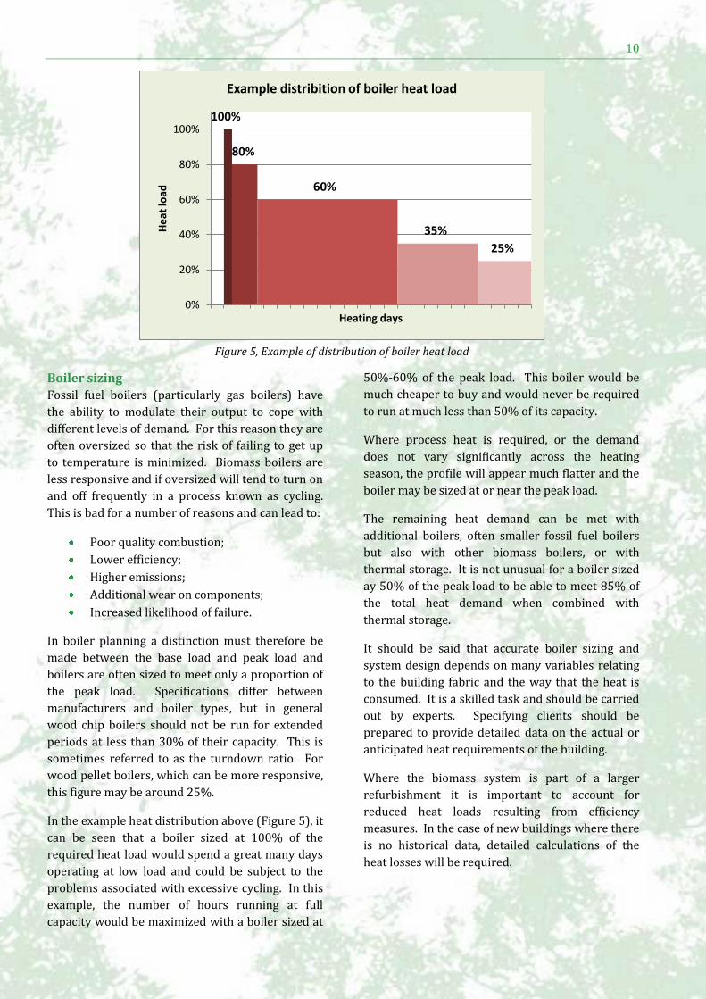
In the example heat distribution above (Figure 5), it
can be seen that a boiler sized at 100% of the
required heat load would spend a great many days
operating at low load and could be subject to the
problems associated with excessive cycling. In this
example, the number of hours running at full
capacity would be maximized with a boiler sized at
50%-60% of the peak load. This boiler would be
much cheaper to buy and would never be required
to run at much less than 50% of its capacity.
Where process heat is required, or the demand
does not vary significantly across the heating
season, the profile will appear much flatter and the
boiler may be sized at or near the peak load.
The remaining heat demand can be met with
additional boilers, often smaller fossil fuel boilers
but also with other biomass boilers, or with
thermal storage. It is not unusual for a boiler sized
ay 50% of the peak load to be able to meet 85% of
the total heat demand when combined with
thermal storage.
It should be said that accurate boiler sizing and
system design depends on many variables relating
to the building fabric and the way that the heat is
consumed. It is a skilled task and should be carried
out by experts. Specifying clients should be
prepared to provide detailed data on the actual or
anticipated heat requirements of the building.
Where the biomass system is part of a larger
refurbishment it is important to account for
reduced heat loads resulting from efficiency
measures. In the case of new buildings where there
is no historical data, detailed calculations of the
heat losses will be required.
100%
80%
60%
35%
25%
0%
20%
40%
60%
80%
100%
He
at lo
ad
Heating days
Example distribition of boiler heat load
Figure 5, Example of distribution of boiler heat load
11 | A guide for specifiers of biomass heating sytems
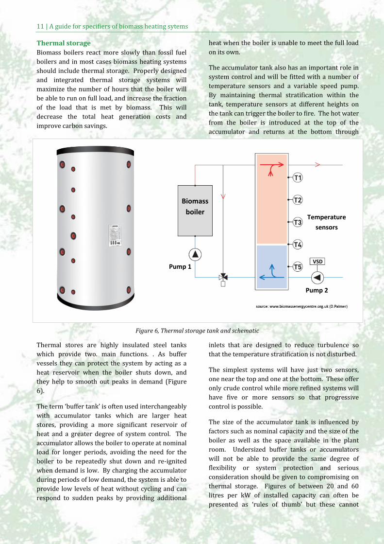
Thermal storage
Biomass boilers react more slowly than fossil fuel
boilers and in most cases biomass heating systems
should include thermal storage. Properly designed
and integrated thermal storage systems will
maximize the number of hours that the boiler will
be able to run on full load, and increase the fraction
of the load that is met by biomass. This will
decrease the total heat generation costs and
improve carbon savings.
Thermal stores are highly insulated steel tanks
which provide two. main functions. . As buffer
vessels they can protect the system by acting as a
heat reservoir when the boiler shuts down, and
they help to smooth out peaks in demand (Figure
6).
The term ‘buffer tank’ is often used interchangeably
with accumulator tanks which are larger heat
stores, providing a more significant reservoir of
heat and a greater degree of system control. The
accumulator allows the boiler to operate at nominal
load for longer periods, avoiding the need for the
boiler to be repeatedly shut down and re-ignited
when demand is low. By charging the accumulator
during periods of low demand, the system is able to
provide low levels of heat without cycling and can
respond to sudden peaks by providing additional
heat when the boiler is unable to meet the full load
on its own.
The accumulator tank also has an important role in
system control and will be fitted with a number of
temperature sensors and a variable speed pump.
By maintaining thermal stratification within the
tank, temperature sensors at different heights on
the tank can trigger the boiler to fire. The hot water
from the boiler is introduced at the top of the
accumulator and returns at the bottom through
inlets that are designed to reduce turbulence so
that the temperature stratification is not disturbed.
The simplest systems will have just two sensors,
one near the top and one at the bottom. These offer
only crude control while more refined systems will
have five or more sensors so that progressive
control is possible.
The size of the accumulator tank is influenced by
factors such as nominal capacity and the size of the
boiler as well as the space available in the plant
room. Undersized buffer tanks or accumulators
will not be able to provide the same degree of
flexibility or system protection and serious
consideration should be given to compromising on
thermal storage. Figures of between 20 and 60
litres per kW of installed capacity can often be
presented as ‘rules of thumb’ but these cannot
Pump 1
Pump 2
VSD
Temperature
sensors
Biomass
boiler
Figure 6, Thermal storage tank and schematic
12
necessarily be relied upon as every system is
different.
Fuel feeding and handling systems
Fuel feeding and handling systems are necessary to
transport the fuel from the point of delivery to
point of storage, and from the storage to the
combustion system. Due to its direct influence on
the availability and performance of the combustion
system, the fuel feeding needs to be designed
carefully and has to be adjusted to the combustion
technology used.
Examples of fuel handling methods include:
Belt conveyors
Augers (screw conveyors)
Walking floors
Pneumatic systems
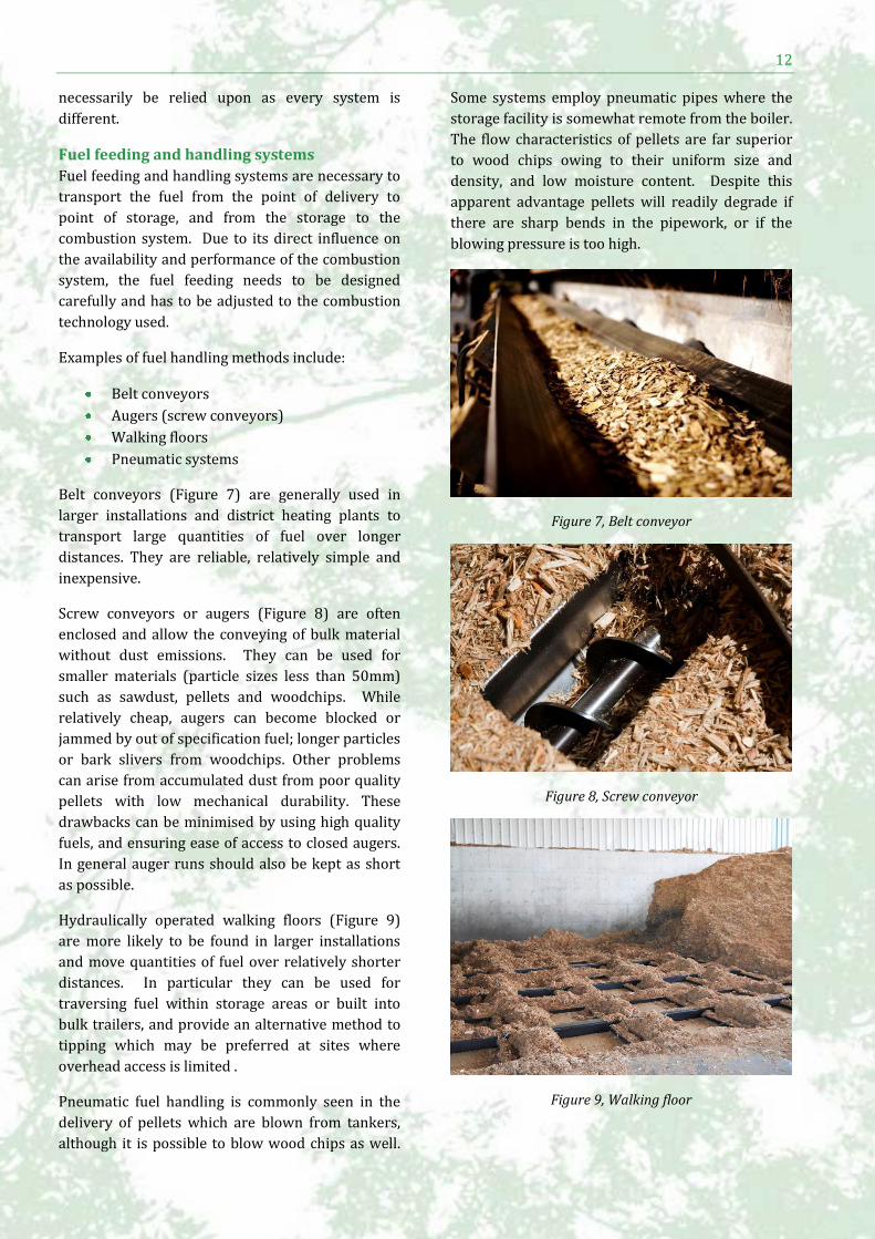
Belt conveyors (Figure 7) are generally used in
larger installations and district heating plants to
transport large quantities of fuel over longer
distances. They are reliable, relatively simple and
inexpensive.
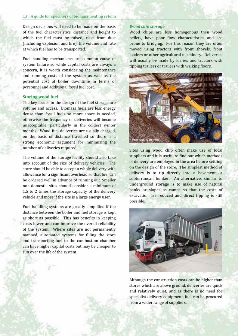
Screw conveyors or augers (Figure 8) are often
enclosed and allow the conveying of bulk material
without dust emissions. They can be used for
smaller materials (particle sizes less than 50mm)
such as sawdust, pellets and woodchips. While
relatively cheap, augers can become blocked or
jammed by out of specification fuel; longer particles
or bark slivers from woodchips. Other problems
can arise from accumulated dust from poor quality
pellets with low mechanical durability. These
drawbacks can be minimised by using high quality
fuels, and ensuring ease of access to closed augers.
In general auger runs should also be kept as short
as possible.
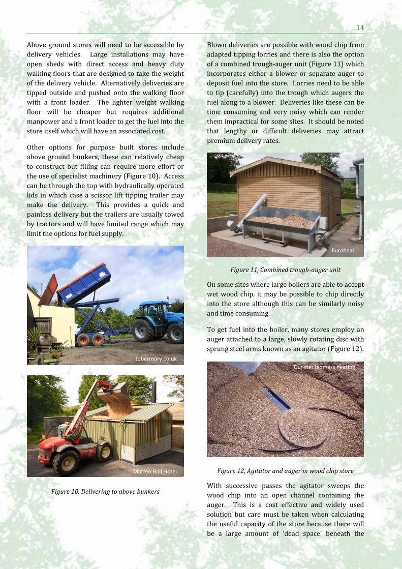
Hydraulically operated walking floors (Figure 9)
are more likely to be found in larger installations
and move quantities of fuel over relatively shorter
distances. In particular they can be used for
traversing fuel within storage areas or built into
bulk trailers, and provide an alternative method to
tipping which may be preferred at sites where
overhead access is limited .
Pneumatic fuel handling is commonly seen in the
delivery of pellets which are blown from tankers,
although it is possible to blow wood chips as well.
Some systems employ pneumatic pipes where the
storage facility is somewhat remote from the boiler.
The flow characteristics of pellets are far superior
to wood chips owing to their uniform size and
density, and low moisture content. Despite this
apparent advantage pellets will readily degrade if
there are sharp bends in the pipework, or if the
blowing pressure is too high.
Figure 7, Belt conveyor
Figure 8, Screw conveyor
Figure 9, Walking floor
13 | A guide for specifiers of biomass heating sytems
Design decisions will need to be made on the basis
of the fuel characteristics, distance and height to
which the fuel must be raised, risks from dust
(including explosion and fire), the volume and rate
at which fuel has to be transported.
Fuel handling mechanisms are common cause of
system failure so while capital costs are always a
concern, it is worth considering the maintenance
and running costs of the system as well as the
potential cost of boiler downtime in terms of
personnel and additional fossil fuel cost.
Storing wood fuel
The key issues in the design of the fuel storage are
volume and access. Biomass fuels are less energy
dense than fossil fuels so more space is needed,
otherwise the frequency of deliveries will become
unacceptable, particularly in the coldest winter
months. Wood fuel deliveries are usually charged,
on the basis of distance travelled so there is a
strong economic argument for minimizing the
number of deliveries required.
The volume of the storage facility should also take
into account of the size of delivery vehicles. The
store should be able to accept a whole delivery with
allowance for a significant overhead so that fuel can
be ordered well in advance of running out. Smaller
non-domestic sites should consider a minimum of
1.5 to 2 times the storage capacity of the delivery
vehicle and more if the site is a large energy user.
Fuel handling systems are greatly simplified if the
distance between the boiler and fuel storage is kept
as short as possible. This has benefits in keeping
costs lower and can improve the overall reliability
of the system. Where sites are not permanently
manned, automated systems for filling the store
and transporting fuel to the combustion chamber
can have higher capital costs but may be cheaper to
run over the life of the system.
Wood chip storage
Wood chips are less homogenous then wood
pellets, have poor flow characteristics and are
prone to bridging. For this reason they are often
moved using tractors with front shovels, front
loaders or other agricultural machinery. Deliveries
will usually be made by lorries and tractors with
tipping trailers or trailers with walking floors.
Sites using wood chip often make use of local
suppliers and it is useful to find out which methods
of delivery are employed in the area before settling
on the design of the store. The simplest method of
delivery is to tip directly into a basement or
subterranean bunker. An alternative, similar to
underground storage is to make use of natural
banks or slopes as ramps so that the costs of
excavation are reduced and direct tipping is still
possible.
Although the construction costs can be higher than
stores which are above ground, deliveries are quick
and relatively quiet, and as there is no need for
specialist delivery equipment, fuel can be procured
from a wider range of suppliers.
Practicality Brown
14
Above ground stores will need to be accessible by
delivery vehicles. Large installations may have
open sheds with direct access and heavy duty
walking floors that are designed to take the weight
of the delivery vehicle. Alternatively deliveries are
tipped outside and pushed onto the walking floor
with a front loader. The lighter weight walking
floor will be cheaper but requires additional
manpower and a front loader to get the fuel into the
store itself which will have an associated cost.
Other options for purpose built stores include
above ground bunkers, these can relatively cheap
to construct but filling can require more effort or
the use of specialist machinery (Figure 10). Access
can be through the top with hydraulically operated
lids in which case a scissor lift tipping trailer may
make the delivery. This provides a quick and
painless delivery but the trailers are usually towed
by tractors and will have limited range which may
limit the options for fuel supply.
Figure 10, Delivering to above bunkers
Blown deliveries are possible with wood chip from
adapted tipping lorries and there is also the option
of a combined trough-auger unit (Figure 11) which
incorporates either a blower or separate auger to
deposit fuel into the store. Lorries need to be able
to tip (carefully) into the trough which augers the
fuel along to a blower. Deliveries like these can be
time consuming and very noisy which can render
them impractical for some sites. It should be noted
that lengthy or difficult deliveries may attract
premium delivery rates.
Figure 11, Combined trough-auger unit
On some sites where large boilers are able to accept
wet wood chip, it may be possible to chip directly
into the store although this can be similarly noisy
and time consuming.
To get fuel into the boiler, many stores employ an
auger attached to a large, slowly rotating disc with
sprung steel arms known as an agitator (Figure 12).
Figure 12, Agitator and auger in wood chip store
With successive passes the agitator sweeps the
wood chip into an open channel containing the
auger. This is a cost effective and widely used
solution but care must be taken when calculating
the useful capacity of the store because there will
be a large amount of ‘dead space’ beneath the
Dunster biomass heating
Euroheat
tobermory.co.uk
Matfen Hall Hotel
15 | A guide for specifiers of biomass heating sytems
agitator which is usually placed at an angle to the
horizontal, and also in the corners of a square or
rectangular store. A range of other auger and
bunker based solutions can be seen in Figure 14.
For sites with difficult access and restricted space
modified hook bins provide another solution
(Figure 13). These are self-contained fuel stores,
with a capacity of around 30m3, which feature an
integral walking floor.
Figure 13, Wood chip hook bins and transverse auger
They are lifted into place from the back of the lorry
and connected directly to an auger system which
supplies the boiler. Seamless operation requires at
least two to three hook bins so that an empty bin
can be replaced with full one in a single visit
without disrupting the operation of the boiler. This
is a quick and clean delivery method but can be
expensive and it may be necessary to sign up to a
longer contact with a single supplier.
Wood chips can have moisture levels anywhere
upwards of 25% and as such need to be considered
as biologically active. The natural action of
microbes breaks down the organic matter releasing
heat in the process and can result in significant loss
of mass if stored for extended periods. Very large
piles of moist woodchip (>8m high) can generate a
significant amount of heat which may have to be
monitored. The production of mould and spores is
potentially damaging to health so all wood chip
stores require ventilation and ‘dead spaces’ within
the store (e.g. corners) should be kept to a
minimum and turned over periodically to prevent
undisturbed fuel from composting. A well
ventilated store will also enhance drying and
improve the energy value of the fuel.
Southwest Woodshed
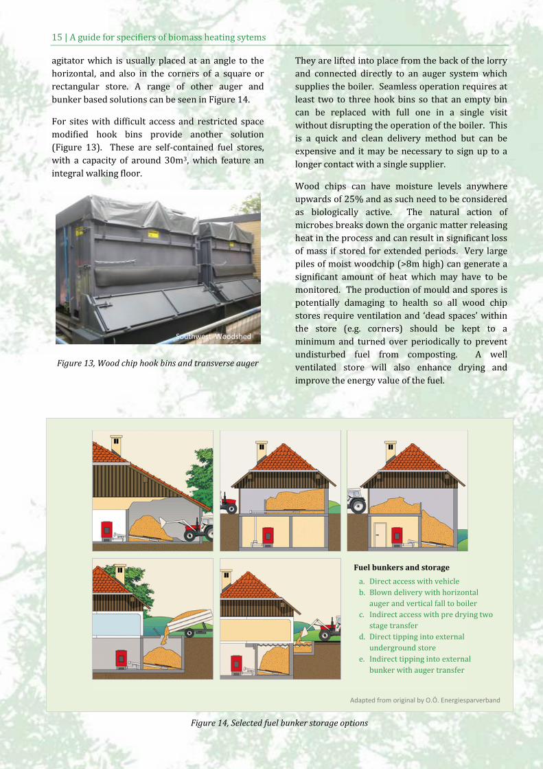
Figure 14, Selected fuel bunker storage options
Fuel bunkers and storage
a. Direct access with vehicle
b. Blown delivery with horizontal
auger and vertical fall to boiler
c. Indirect access with pre drying two
stage transfer
d. Direct tipping into external
underground store
e. Indirect tipping into external
bunker with auger transfer
Adapted from original by O.Ö. Energiesparverband
16
Pellet storage
For many sites, pellet systems provide additional
flexibility and enable biomass to be installed where
wood chip systems would be difficult. Pellets are
energy dense, relatively easy to transport and
blown deliveries are possible at many sites. Almost
any site that has been serviced by oil tankers can
benefit from pellet heating.
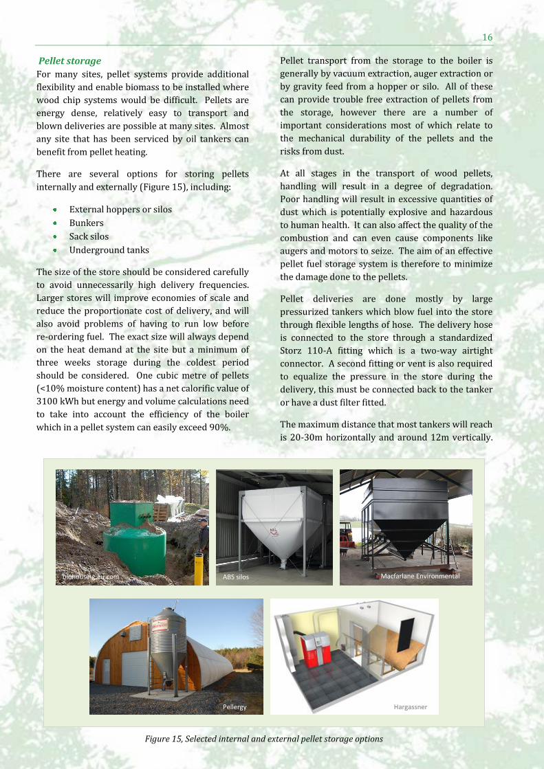
There are several options for storing pellets
internally and externally (Figure 15), including:
External hoppers or silos
Bunkers
Sack silos
Underground tanks
The size of the store should be considered carefully
to avoid unnecessarily high delivery frequencies.
Larger stores will improve economies of scale and
reduce the proportionate cost of delivery, and will
also avoid problems of having to run low before
re-ordering fuel. The exact size will always depend
on the heat demand at the site but a minimum of
three weeks storage during the coldest period
should be considered. One cubic metre of pellets
(<10% moisture content) has a net calorific value of
3100 kWh but energy and volume calculations need
to take into account the efficiency of the boiler
which in a pellet system can easily exceed 90%.
Pellet transport from the storage to the boiler is
generally by vacuum extraction, auger extraction or
by gravity feed from a hopper or silo. All of these
can provide trouble free extraction of pellets from
the storage, however there are a number of
important considerations most of which relate to
the mechanical durability of the pellets and the
risks from dust.
At all stages in the transport of wood pellets,
handling will result in a degree of degradation.
Poor handling will result in excessive quantities of
dust which is potentially explosive and hazardous
to human health. It can also affect the quality of the
combustion and can even cause components like
augers and motors to seize. The aim of an effective
pellet fuel storage system is therefore to minimize
the damage done to the pellets.
Pellet deliveries are done mostly by large
pressurized tankers which blow fuel into the store
through flexible lengths of hose. The delivery hose
is connected to the store through a standardized
Storz 110-A fitting which is a two-way airtight
connector. A second fitting or vent is also required
to equalize the pressure in the store during the
delivery, this must be connected back to the tanker
or have a dust filter fitted.
The maximum distance that most tankers will reach
is 20-30m horizontally and around 12m vertically.
biohousing.eu.com ABS silos Macfarlane Environmental
Pellergy Hargassner
Figure 15, Selected internal and external pellet storage options
17 | A guide for specifiers of biomass heating sytems
Beyond this the delivery pressure will have to be
too high and the pellets will get damaged. Most
pellet suppliers will be happy to advise on the
access requirements for lorries, including minimum
widths, heights and space for turning. While these
distances can give a good degree of flexibility when
siting the fuel store, every effort should be made to
minimize the distance to avoid unnecessary
damage to the pellets.
As well as keeping the distance to a minimum,
pipework should be kept straight as straight as
possible and sharp bends (<0.5m) avoided
altogether. Delivery pipes need to be smooth on
the inside and should be made of a conducting
material such as metal which should be earthed;
plastic pipes can build up a static charge which
could become a source of ignition in a dusty
environment. The system should also be earthed.
It is important that the inlet to the pellet store is at
least 2.5 metres from the opposite wall to prevent
the blown pellets disintegrating on impact. In
smaller stores a baffle or crash mat may be placed a
short distance in front of the rear wall to reduce the
impact or hoses may be angled to improve and
increase the length of the pellet trajectory.
Wood pellets have good flow characteristics and
providing the slope of the floor is smooth, and
greater than 40-45 degrees, they should flow freely
into the auger extraction system to the boiler. A
sight glass may be fitted so that levels can be
inspected and some suppliers offer ultrasonic and
electronic level indicators with internet or mobile
connections to allow automatic ordering.
While pellets have much lower moisture content
than wood chip and can be stored almost
indefinitely in the right environment, they are not
biologically inert. Even in small quantities, pellets
can release dangerous quantities of carbon
monoxide and should be thoroughly ventilated at
all times. Other oxygen depleting gases can be also
present. Individuals should not put their heads in,
or enter confined pellet storage spaces alone or
without checking levels of CO and oxygen.
Ash and emissions As well as what goes into the boiler it is important
to consider what comes out.
Ash characteristics vary according to fuel type with
higher quality fuels generally creating less ash. For
top quality wood pellets ash content should be less
than 0.7% by weight and can even be as low as
0.3-0.5% depending on the combustion conditions.
Good quality wood chip will produce more ash at
around 1-1.5%. Lower quality material will
produce more ash depending on the amount of bark
and foliage that is included. Bark for instance can
produce up to 3% ash by weight and foliage up to
6%.
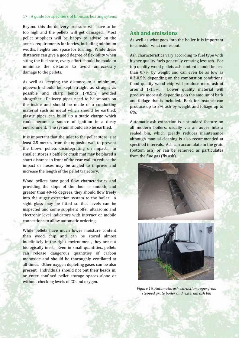
Automatic ash extraction is a standard feature on
all modern boilers, usually via an auger into a
sealed bin, which greatly reduces maintenance
although manual cleaning is also recommended at
specified intervals. Ash can accumulate in the grate
(bottom ash) or can be removed as particulates
from the flue gas (fly ash).
Figure 16, Automatic ash extraction auger from stepped grate boiler and external ash bin
18
Bottom ash can be used as a fertilizer as it contains
large amounts of potassium although high alkalinity
means that it should be spread thinly. In Sweden
the maximum rate of spreading is 3 tonnes per
hectare. Other uses include blending with cement
and concrete and the manufacture of lightweight
cinder blocks.
Fly ash is produced in much smaller quantities but
should not be used as fertilizer as it contains heavy
metals. Larger particles can be efficiently removed
using a cyclone or multi cyclone, a kind of
centrifugal gravity separator through which the flue
gas is passed.
Finer particulates (PM10 and PM2.5) are not
sufficiently massive to be removed by the cyclone
so ceramic filters are used. These are more
expensive option but can be retrofitted to existing
boilers removing up to 96% of PM10 and PM2.5.
Other emissions from biomass combustion which
may be regulated include oxides of nitrogen and
sulphur (SOX and NOX) as well as carbon dioxide
(CO2). Levels depend to a large extent on the fuels
and equipment used and on the mode of operation
Emissions of NOX can vary between 60 mg/MJ and
170 mg/MJ which is high compared to gas
(5-20 mg/MJ) and oil (50-70 mg/MJ). However
biomass installations typically replace oil or solid
fuels in low density or rural areas, so impacts can
be expected to be relatively low. By comparison
diesel cars can be expected to produce 440-530
mg/km (at ground level) or more when cold
starting is taken into consideration. Over a year,
NOX emissions from a 150kW chip boiler could be
expected to be equivalent to a single medium sized
car doing an average of 24,000km.
Biomass has rather lower emission of SOX
(20 mg/MJ) than oil or (140 mg/MJ) or coal
(900 mg/MJ), but more than natural gas
(<1 mg/MJ). Emissions of CO2 from biomass
combustion are relatively high, although
sustainably sourced biomass fuel can claim to be
almost carbon neutral as a result of a relatively
short carbon cycle, based around the fresh growth
and replacement of existing forests.
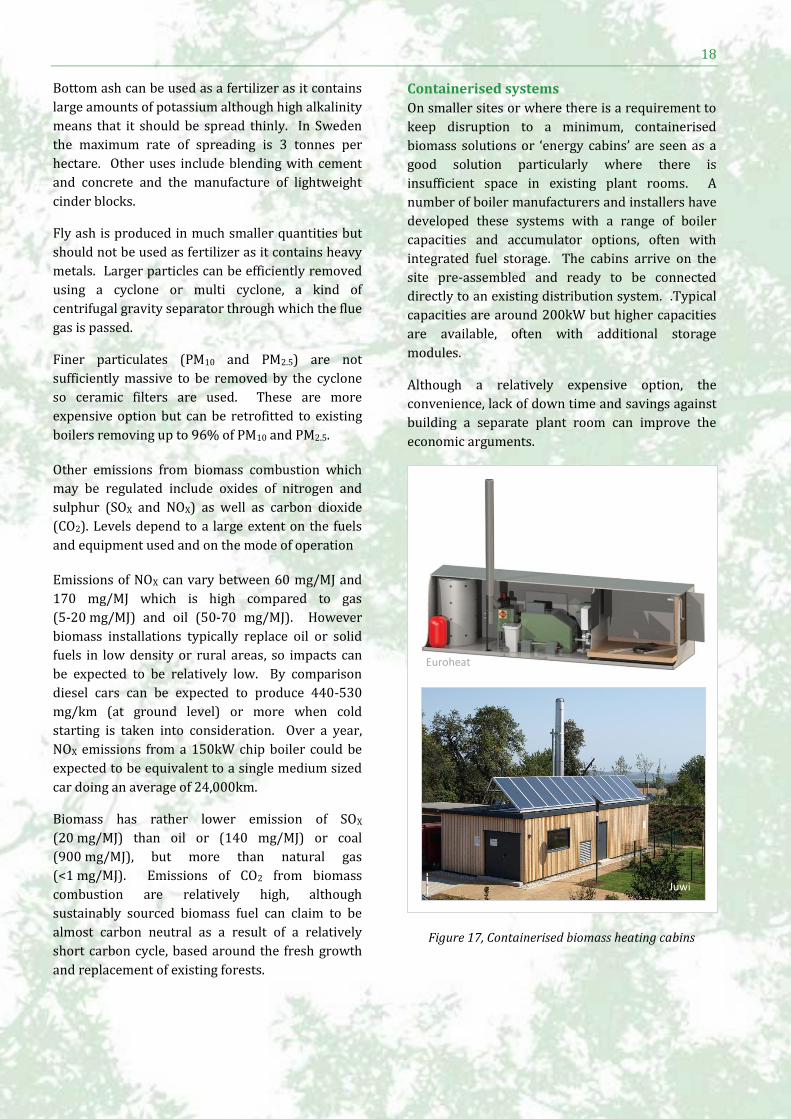
Containerised systems
On smaller sites or where there is a requirement to
keep disruption to a minimum, containerised
biomass solutions or ‘energy cabins’ are seen as a
good solution particularly where there is
insufficient space in existing plant rooms. A
number of boiler manufacturers and installers have
developed these systems with a range of boiler
capacities and accumulator options, often with
integrated fuel storage. The cabins arrive on the
site pre-assembled and ready to be connected
directly to an existing distribution system. .Typical
capacities are around 200kW but higher capacities
are available, often with additional storage
modules.
Although a relatively expensive option, the
convenience, lack of down time and savings against
building a separate plant room can improve the
economic arguments.
Figure 17, Containerised biomass heating cabins
Euroheat
Juwi
19 | A guide for specifiers of biomass heating sytems
District heating District heating is often associated with biomass.
High and consistent base loads are well suited to
the operation of biomass boilers and the
opportunity to spread capital costs over a number
of properties can make economic returns more
attractive. There are other benefits to having
centralised plant and fuel storage which can more
efficient in space and in energy terms.
Heat networks can be implemented at different
scales ranging from a handful of connected sites up
to whole towns or cities properties. Urban areas
are generally favoured due to the cost of pipe work
and density of heat users. Where there is sufficient
demand, district cooling can also be provide
through absorption cooling technologies.
Key parameters for judging and comparing the
feasibility of a district heating system include the
areal energy density and the line load. Areal energy
density is the ratio of the total energy demand (in
MWh or GWh) and the geographical area (in km2)
of the proposed system. The line load is the ratio
between the total energy demand and the total
length of pipes (in km) in the network. Values will
vary between regions, in Sweden for example, an
annual areal density of 5 MWh/km2 (or 5 kWh/m2)
and line loads of between 200-300 Kwh/m would
be would be considered acceptable. Areal energy
densities can be increased by incorporating larger
heat users which can provide a good base load for
the system. Low line loads indicate relatively high
system losses from pipework which may be
remedied by relocating the plant room or
re-routing the network.
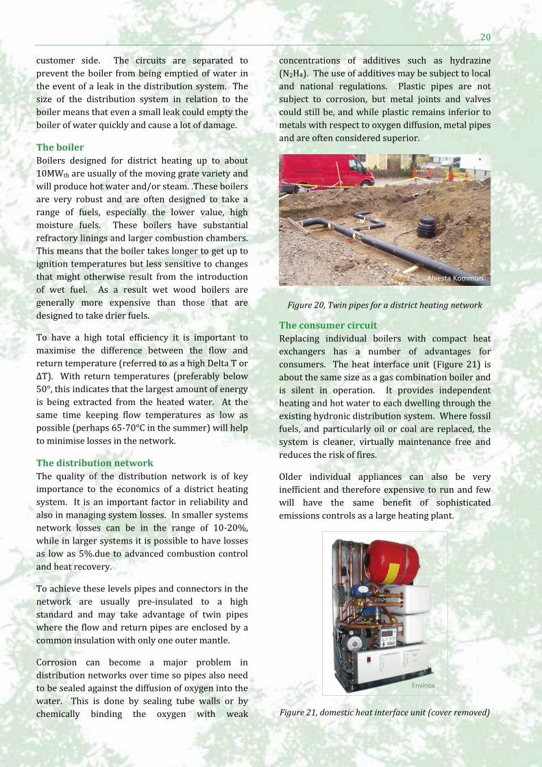
District heating systems will contain three circuits
(Figure 19), one for the boiler, one for the
distribution network and one circuit for the
consumer. Within the consumer circuit there is
separate circuit for domestic hot water. The
circuits are thermally connected by two plate heat
exchangers, one on the boiler side and one on the
Fuel
Bo
ile
r
Boiler
circuit
Distribution
circuit Consumer
circuit Linnæus University
Figure 19, Circuits in a district heating system
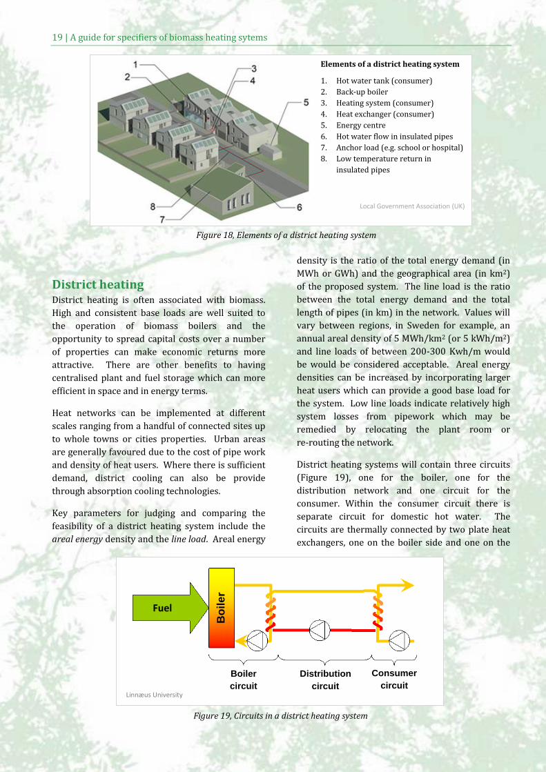
Elements of a district heating system
1. Hot water tank (consumer)
2. Back-up boiler
3. Heating system (consumer)
4. Heat exchanger (consumer)
5. Energy centre
6. Hot water flow in insulated pipes
7. Anchor load (e.g. school or hospital)
8. Low temperature return in
insulated pipes
Local Government Association (UK)
Figure 18, Elements of a district heating system
20
customer side. The circuits are separated to
prevent the boiler from being emptied of water in
the event of a leak in the distribution system. The
size of the distribution system in relation to the
boiler means that even a small leak could empty the
boiler of water quickly and cause a lot of damage.
The boiler
Boilers designed for district heating up to about
10MWth are usually of the moving grate variety and
will produce hot water and/or steam. .These boilers
are very robust and are often designed to take a
range of fuels, especially the lower value, high
moisture fuels. These boilers have substantial
refractory linings and larger combustion chambers.
This means that the boiler takes longer to get up to
ignition temperatures but less sensitive to changes
that might otherwise result from the introduction
of wet fuel. As a result wet wood boilers are
generally more expensive than those that are
designed to take drier fuels.
To have a high total efficiency it is important to
maximise the difference between the flow and
return temperature (referred to as a high Delta T or
ΔT). With return temperatures (preferably below
50°, this indicates that the largest amount of energy
is being extracted from the heated water. At the
same time keeping flow temperatures as low as
possible (perhaps 65-70°C in the summer) will help
to minimise losses in the network.
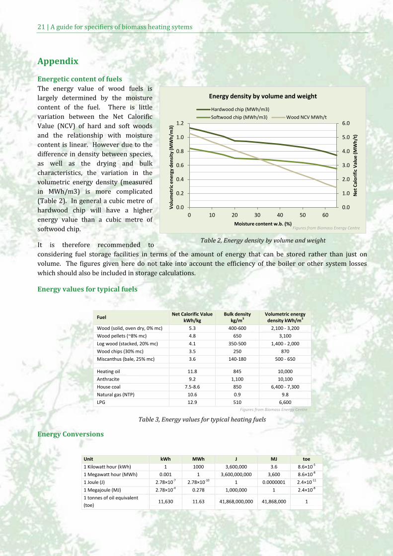
The distribution network
The quality of the distribution network is of key
importance to the economics of a district heating
system. It is an important factor in reliability and
also in managing system losses. In smaller systems
network losses can be in the range of 10-20%,
while in larger systems it is possible to have losses
as low as 5%.due to advanced combustion control
and heat recovery.
To achieve these levels pipes and connectors in the
network are usually pre-insulated to a high
standard and may take advantage of twin pipes
where the flow and return pipes are enclosed by a
common insulation with only one outer mantle.
Corrosion can become a major problem in
distribution networks over time so pipes also need
to be sealed against the diffusion of oxygen into the
water. This is done by sealing tube walls or by
chemically binding the oxygen with weak
concentrations of additives such as hydrazine
(N2H4). The use of additives may be subject to local
and national regulations. Plastic pipes are not
subject to corrosion, but metal joints and valves
could still be, and while plastic remains inferior to
metals with respect to oxygen diffusion, metal pipes
and are often considered superior.
Figure 20, Twin pipes for a district heating network
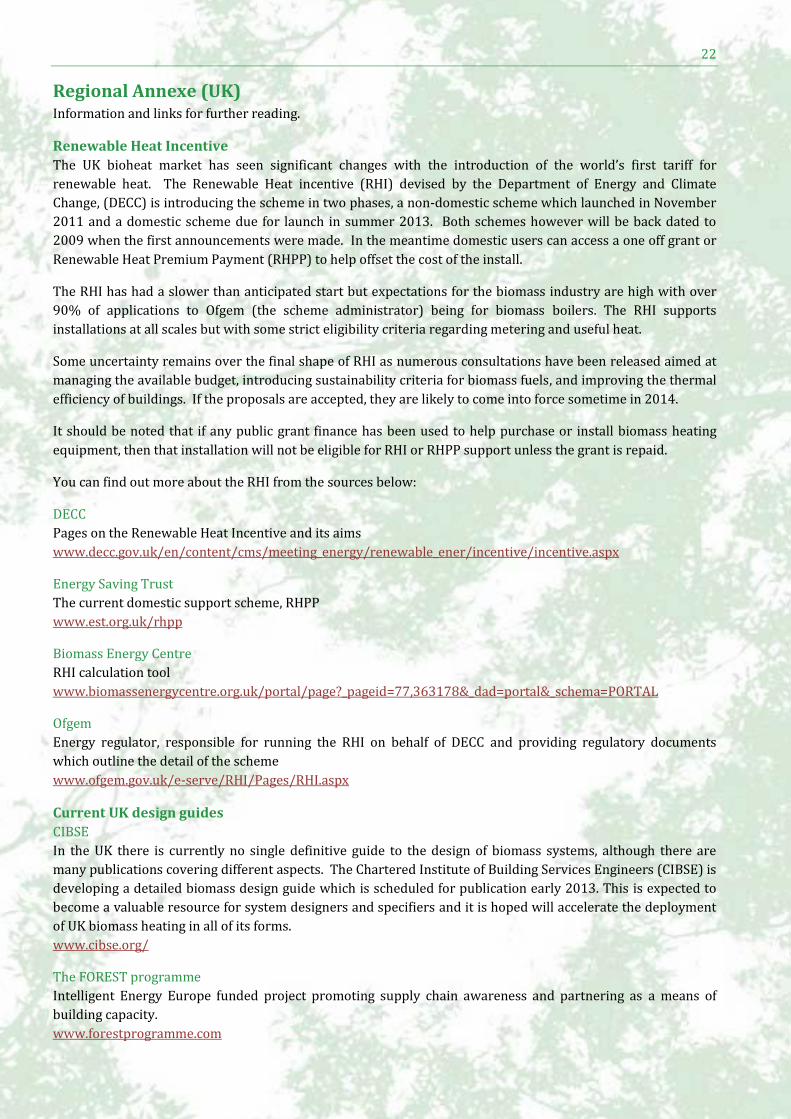
The consumer circuit
Replacing individual boilers with compact heat
exchangers has a number of advantages for
consumers. The heat interface unit (Figure 21) is
about the same size as a gas combination boiler and
is silent in operation. It provides independent
heating and hot water to each dwelling through the
existing hydronic distribution system. Where fossil
fuels, and particularly oil or coal are replaced, the
system is cleaner, virtually maintenance free and
reduces the risk of fires.
Older individual appliances can also be very
inefficient and therefore expensive to run and few
will have the same benefit of sophisticated
emissions controls as a large heating plant.
Figure 21, domestic heat interface unit (cover removed)
Envinox
Alvesta Kommun
21 | A guide for specifiers of biomass heating sytems
Appendix
Energetic content of fuels
The energy value of wood fuels is
largely determined by the moisture
content of the fuel. There is little
variation between the Net Calorific
Value (NCV) of hard and soft woods
and the relationship with moisture
content is linear. However due to the
difference in density between species,
as well as the drying and bulk
characteristics, the variation in the
volumetric energy density (measured
in MWh/m3) is more complicated
(Table 2). In general a cubic metre of
hardwood chip will have a higher
energy value than a cubic metre of
softwood chip.
It is therefore recommended to
considering fuel storage facilities in terms of the amount of energy that can be stored rather than just on
volume. The figures given here do not take into account the efficiency of the boiler or other system losses
which should also be included in storage calculations.
Energy values for typical fuels
Fuel Net Calorific Value
kWh/kg Bulk density
kg/m3 Volumetric energy
density kWh/m3
Wood (solid, oven dry, 0% mc) 5.3 400-600 2,100 - 3,200
Wood pellets (~8% mc) 4.8 650 3,100
Log wood (stacked, 20% mc) 4.1 350-500 1,400 - 2,000
Wood chips (30% mc) 3.5 250 870
Miscanthus (bale, 25% mc) 3.6 140-180 500 - 650
Heating oil 11.8 845 10,000
Anthracite 9.2 1,100 10,100
House coal 7.5-8.6 850 6,400 - 7,300
Natural gas (NTP) 10.6 0.9 9.8
LPG 12.9 510 6,600
Figures from Biomass Energy Centre
Table 3, Energy values for typical heating fuels
Energy Conversions
Unit kWh MWh J MJ toe
1 Kilowatt hour (kWh) 1 1000 3,600,000 3.6 8.6×10⁻⁵
1 Megawatt hour (MWh) 0.001 1 3,600,000,000 3,600 8.6×10⁻⁸
1 Joule (J) 2.78×10⁻⁷ 2.78×10⁻¹⁰ 1 0.0000001 2.4×10⁻¹¹
1 Megajoule (MJ) 2.78×10⁻⁴ 0.278 1,000,000 1 2.4×10⁻⁸
1 tonnes of oil equivalent
(toe) 11,630 11.63 41,868,000,000 41,868,000 1
0.0
1.0
2.0
3.0
4.0
5.0
6.0
0.0
0.2
0.4
0.6
0.8
1.0
1.2
0 10 20 30 40 50 60
Ne
t C
alo
rifi
c V
alu
e (
MW
h/t
)
Vo
lum
etr
ic e
ne
rgy
de
nsi
ty (
MW
h/m
3)
Moisture content w.b. (%)
Energy density by volume and weight
Hardwood chip (MWh/m3)
Softwood chip (MWh/m3) Wood NCV MWh/t
Figures from Biomass Energy Centre
Table 2, Energy density by volume and weight
22
Regional Annexe (UK) Information and links for further reading.
Renewable Heat Incentive
The UK bioheat market has seen significant changes with the introduction of the world’s first tariff for
renewable heat. The Renewable Heat incentive (RHI) devised by the Department of Energy and Climate
Change, (DECC) is introducing the scheme in two phases, a non-domestic scheme which launched in November
2011 and a domestic scheme due for launch in summer 2013. Both schemes however will be back dated to
2009 when the first announcements were made. In the meantime domestic users can access a one off grant or
Renewable Heat Premium Payment (RHPP) to help offset the cost of the install.
The RHI has had a slower than anticipated start but expectations for the biomass industry are high with over
90% of applications to Ofgem (the scheme administrator) being for biomass boilers. The RHI supports
installations at all scales but with some strict eligibility criteria regarding metering and useful heat.
Some uncertainty remains over the final shape of RHI as numerous consultations have been released aimed at
managing the available budget, introducing sustainability criteria for biomass fuels, and improving the thermal
efficiency of buildings. If the proposals are accepted, they are likely to come into force sometime in 2014.
It should be noted that if any public grant finance has been used to help purchase or install biomass heating
equipment, then that installation will not be eligible for RHI or RHPP support unless the grant is repaid.
You can find out more about the RHI from the sources below:
DECC
Pages on the Renewable Heat Incentive and its aims
www.decc.gov.uk/en/content/cms/meeting_energy/renewable_ener/incentive/incentive.aspx
Energy Saving Trust
The current domestic support scheme, RHPP
www.est.org.uk/rhpp
Biomass Energy Centre
RHI calculation tool
www.biomassenergycentre.org.uk/portal/page?_pageid=77,363178&_dad=portal&_schema=PORTAL
Ofgem
Energy regulator, responsible for running the RHI on behalf of DECC and providing regulatory documents
which outline the detail of the scheme
www.ofgem.gov.uk/e-serve/RHI/Pages/RHI.aspx
Current UK design guides
CIBSE
In the UK there is currently no single definitive guide to the design of biomass systems, although there are
many publications covering different aspects. The Chartered Institute of Building Services Engineers (CIBSE) is
developing a detailed biomass design guide which is scheduled for publication early 2013. This is expected to
become a valuable resource for system designers and specifiers and it is hoped will accelerate the deployment
of UK biomass heating in all of its forms.
www.cibse.org/
The FOREST programme
Intelligent Energy Europe funded project promoting supply chain awareness and partnering as a means of
building capacity.
www.forestprogramme.com
23 | A guide for specifiers of biomass heating sytems
Other FOREST guides:
Partnerships for Success, a guide to partnership working in the biomass supply chain
www.forestprogramme.com/files/2011/05/Forest-Guide_FAW_LR_SP.pdf
A guide to biomass heating standards
www.forestprogramme.com/files/2011/05/FOREST-Standard-Guide_V04_UK.pdf
The FOREST online training tool (developed by Linnæus University)
www.forestprogramme.com/tools-resources/training-tool/
Carbon Trust
A wide range of tools, guides and case studies
www.carbontrust.com/resources/guides/renewable-energy-technologies/biomass-heating-tools-and-
guidance
Biomass heating, a practical guide for potential users (CTG012)
www.carbontrust.com/resources/guides/renewable-energy-technologies/biomass-heating-tools-and-
guidance
Biomass fuel procurement guide
www.carbontrust.com/media/88607/ctg074-biomass-fuel-procurement-guide.pdf
Biomass Energy Centre (BEC)
Government sponsored biomass portal covering all aspects of biomass heating including technical,
environmental and regulatory matters
www.biomassenergycentre.org.uk
Recent BEC guides:
Biomass heating: A guide to medium scale wood chip and wood pellet systems
www.biomassenergycentre.org.uk/pls/portal/docs/PAGE/BEC_TECHNICAL/BEST%20PRACTICE/378
21_FOR_BIOMASS_2_LR.PDF
Biomass heating: a guide to feasibility studies
www.biomassenergycentre.org.uk/pls/portal/docs/PAGE/BEC_TECHNICAL/BEST%20PRACTICE/382
15_FOR_BIOMASS_3_LR.PDF
Planning permission
Planning guidance for general building improvements can be found at the government online portal.
http://www.planningportal.gov.uk
Planning permission is not generally required to install a biomass boiler although aspects of the system may
fall within planning regulations. Permanent fuel storage or additions to plant buildings, access arrangements
and flue positioning are all subject to the same rules as for ordinary buildings. However recent changes to
‘permitted developments’ (changes that can be without planning permission) for example, include biomass
boiler flues on a rear elevation as long as they are within one metre of the highest part of the ridge. Listed
buildings and those in designated areas may be subject to additional requirements and local planning
departments should be consulted.
www.planningportal.gov.uk/permission/commonprojects/biomass
Building Regulations
Building regulations for England and Wales should be adhered to for all developments, including the
installation of combustion equipment. The building regulations and Approved Documents are free to download
and regularly updated. For a biomass installation, a number of sections of the building regulations will apply
such as:
Part L: Conservation of Fuel and Power
www.planningportal.gov.uk/buildingregulations/approveddocuments/partl/approved
24
Part J: Heat producing appliances
http://www.planningportal.gov.uk/buildingregulations/approveddocuments/partj/
Air Quality
The UK government is gradually introducing more stringent carbon dioxide and particulate matter
requirements on boilers eligible for financial support (RHI and RHPP). In addition, many built up areas of the
UK are deemed Air Quality Management Areas (AQMA) or ‘Smoke Control Areas’. An AQMA can be declared by
a Local Authority if air quality falls below required standards. Additionally a Smoke Control Area can be
declared which means that only authorised fuels or exempted boilers can be used.
Local government rules
www.gov.uk/preventing-air-pollution/local-controls
AQMA and smoke control pages at Defra
http://aqma.defra.gov.uk/
http://smokecontrol.defra.gov.uk/
Maps of all AQMAs are also available:
http://aqma.defra.gov.uk/maps.php
Most modern biomass boilers are sufficiently clean to be permitted in smoke control areas, and indeed are
already meeting the proposed UK CO2 and NOX and particulate limits. Details on the mechanism for ensuring
that RHI financial support is only given to biomass boilers capable of complying with emission limits is now in
the Defra Archive:
http://archive.defra.gov.uk/environment/quality/industrial/guidance/rhi-guidance.pdf
Grants and support
The Forestry Commission, English Woodland Grant Scheme (EWGS), offers six grants for Woodland
Management, including the Woodland Woodfuel Implementation Grant (WWIG). This grant provides specific
assistance for woodland owners providing infrastructure support for sustainable wood fuel extraction.
www.forestry.gov.uk/ewgs
In the south west, the Ward Forester project is a Devon based pilot initiative led jointly by Devon County
Council and the Forestry Commission. It aims, to bring small undermanaged woodlands back into active
management by bringing them together into economically viable, cooperating groups under the stewardship
and expertise of a professional forester. Additional income from wood fuel can be a trigger for better
management of forest resources.
www.wardforester.co.uk
Standards and assurance
Biomass boiler manufacturers will always specify which grades of fuel the appliance is designed to take. This is
essential to the operation of the boiler and users should always use the right fuel for their. Details of fuel and
other standards relevant to the biomass industry are available on the FOREST website.
www.forestprogramme.com/tools-resources/guides
The best way to ensure that fuel is within these specifications is to use an accredited supplier.
In the South West region the Woodsure is a not for profit organisation offering a quality assurance standard’
scheme, it provides an accreditation service to wood fuel suppliers based on recognised standards for physical
and combustion properties as well as sustainability. Information and advice on fuel quality is provided for end
users and a directory of approved suppliers is also provided.
www.woodsure.co.uk
Nationally HETAS is the official body recognised by Government to approve biomass and solid fuel domestic
heating appliances, fuels and services including the registration of competent installers and servicing
businesses. HETAS provide product approval and installer registration services as well as details of approved
25 | A guide for specifiers of biomass heating sytems
retailer and wood fuel suppliers.
www.hetas.co.uk
Users of pellet appliances should be aware that national pellet standards were replaced by the European
ENplus14961-2 standard in August 2011, and is the key standard that all stakeholders should now follow.
www.enplus-pellets.eu
Woodfuel Suppliers group
The Renewable Energy Association (REA) and Confederation of Forest Industries (ConFor) jointly sponsor the
Woodfuel Suppliers Group, a special interest group (SIG) to support and promote businesses on the supply
side. It now encompasses all aspects of the supply chain, including installers and consultants. Pivotally, it has
created a charter for membership promoting fuel quality assurance and sustainable practices.
www.confor.org.uk/AboutUs/Default.aspx?pid=331
Further guidance
The FOREST Partners offer local and regional support to business and individuals:
RegenSW
www.regensw.co.uk
Severn Wye Energy Agency
www.swea.co.uk
Forestry Commission (England)
http://www.forestry.gov.uk/southwest
University of Exeter, Centre for Energy and the Environment
www.exeter.ac.uk/cee
26
BACK COVER
Disclaimer
The sole responsibility for the content of this publication lies with the authors. It does not necessarily reflect the opinion of the European
Communities. The European Commission is not responsible for any use that may be made of the information contained therein.