
1-58503-270-0 -- GibbsCAM 2005 Tutorial - SDC Publications
20
GibbsCAM Tutorial Version 2005 JEFF HATLEY SDC Schroff Development Corporation www.schroff.com www.schroff-europe.com PUBLICATIONS
Transcript of 1-58503-270-0 -- GibbsCAM 2005 Tutorial - SDC Publications

GibbsCAM
Tutorial
Version 2005
JEFF HATLEY
SDC
Schroff Development Corporation
www.schroff.com
www.schroff-europe.com
PUBLICATIONS

Copyrighted Material
Copyrighted
Material
Copyrighted Material
Copyrighted
Material
GibbsCAM Tutorial
125
Chapter 4
Mill
Introduction
For each exercise in this chapter you will open a part file that contains CAD
geometry. You will then set up the tools needed to machine the part, create
machining processes, simulate them, and post process the machining
operations to generate CNC code. Part files for the exercises in this chapter can be downloaded at www.schroff1.com.
Note: For the exercises in this chapter, activate balloons (found under
Help in the Main Menu). This will allow you to view a full explanation
of all of the data entry fields you will see in the tool creation and
machining dialog boxes as you complete the exercises.
Exercise 1 – Drilling
In this exercise you will drill holes for the points you created in Chapter 2 –
Exercise 2.
Choose File-Open from the Main Menu.

Copyrighted Material
Copyrighted
Material
Copyrighted Material
Copyrighted
Material
GibbsCAM Tutorial
126
Select the file POINTS.vnc and click on Open. The CAD geometry for this
part consists of points that will be used for drilling operations.
Select the Tools icon in the Top Level Palette to open up the Tool List.
Double click on Tile 1 in the Tool List to create the first tool.

Copyrighted Material
Copyrighted
Material
Copyrighted Material
Copyrighted
Material
Drilling
127
The Tool Creation dialog box will appear. Select the Spot D (spot drill) as
the tool type. Enter the values in the diagram to define the size of the tool.
Close the Tool 1 dialog box.
The tool will appear in the Tool List.

Copyrighted Material
Copyrighted
Material
Copyrighted Material
Copyrighted
Material
GibbsCAM Tutorial
128
Double click on Tile 2 in the Tool List to create the second tool.

Copyrighted Material
Copyrighted
Material
Copyrighted Material
Copyrighted
Material
Drilling
129
The Tool Creation dialog box will appear. Select Drill as the tool type.
Enter the values shown on the next graphic to define the size of the tool.
Close the Tool 2 dialog box. The tool will appear in the Tool List.

Copyrighted Material
Copyrighted
Material
Copyrighted Material
Copyrighted
Material
GibbsCAM Tutorial
130
Double-click on Tile 3 in the Tool List.
The Tool Creation dialog box wil appear. Select C. Sink (counter sink) and
enter the values as shown to define the size of the tool.
Close the dialog box. Tool 3 will now appear in the Tool List.

Copyrighted Material
Copyrighted
Material
Copyrighted Material
Copyrighted
Material
Drilling
131
You are now ready to begin the machining operations. Select the CAM icon
on the Top Level Palette to open the Machining Palette, Process List, and
Operations List.
Machining operations are created by dragging a tool from the Tool List and
a machining function from the Machining Palette on to the Process List.
Drag Tool 1 from the Tool List to Tile 1 of the process list as shown in the
next graphic.

Copyrighted Material
Copyrighted
Material
Copyrighted Material
Copyrighted
Material
GibbsCAM Tutorial
132
Tool 1 will now appear in the Process List. Drag the Holes icon from the
Machining Palette to Tile 1 of the process list as shown in the next graphic.

Copyrighted Material
Copyrighted
Material
Copyrighted Material
Copyrighted
Material
Drilling
133
The Process Holes dialog box will appear. Enter the values as shown.

Copyrighted Material
Copyrighted
Material
Copyrighted Material
Copyrighted
Material
GibbsCAM Tutorial
134
Close the dialog box. Hold down the shift key and drag a box around the
points as shown.
Click on Do It on the Machining Palette.
Change your view to an isometric view to see the toolpath.

Copyrighted Material
Copyrighted
Material
Copyrighted Material
Copyrighted
Material
Drilling
135
To begin the next operation, select Tile 2 in the Operations List.

Copyrighted Material
Copyrighted
Material
Copyrighted Material
Copyrighted
Material
GibbsCAM Tutorial
136
Drag Tile 1 from the Process List to the Trash Can.
Click on the Render Icon on the Top Level Palette.
Copyrighted Material
Copyrighted
Material
Copyrighted Material
Copyrighted
Material
Drilling
137
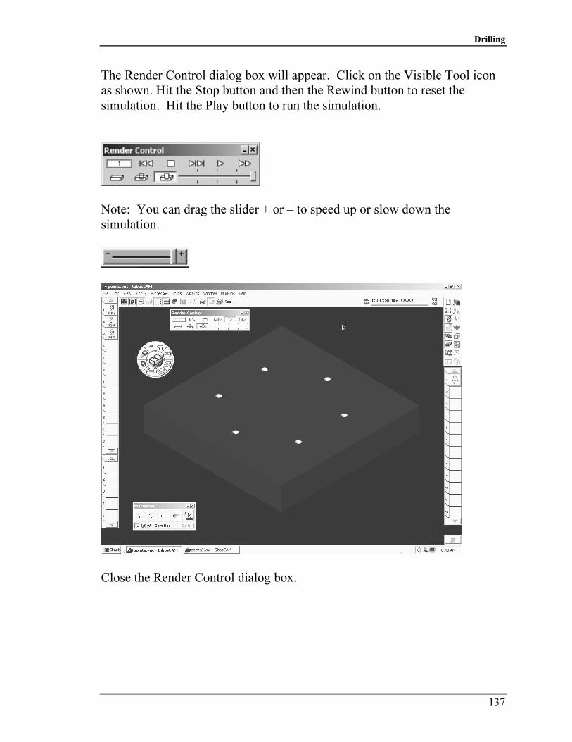
The Render Control dialog box will appear. Click on the Visible Tool icon
as shown. Hit the Stop button and then the Rewind button to reset the
simulation. Hit the Play button to run the simulation.
Note: You can drag the slider + or – to speed up or slow down the
simulation.
Close the Render Control dialog box.

Copyrighted Material
Copyrighted
Material
Copyrighted Material
Copyrighted
Material
GibbsCAM Tutorial
138
Drag the Tool 2 from the Tool List to Tile 1 of the Process List.
Drag the Drilling Icon from the Machining Palette to Tile 1 of the Process
List.

Copyrighted Material
Copyrighted
Material
Copyrighted Material
Copyrighted
Material
Drilling
139
The Process Holes dialog box will appear. Enter the values as shown.
Copyrighted Material
Copyrighted
Material
Copyrighted Material
Copyrighted
Material
GibbsCAM Tutorial
140
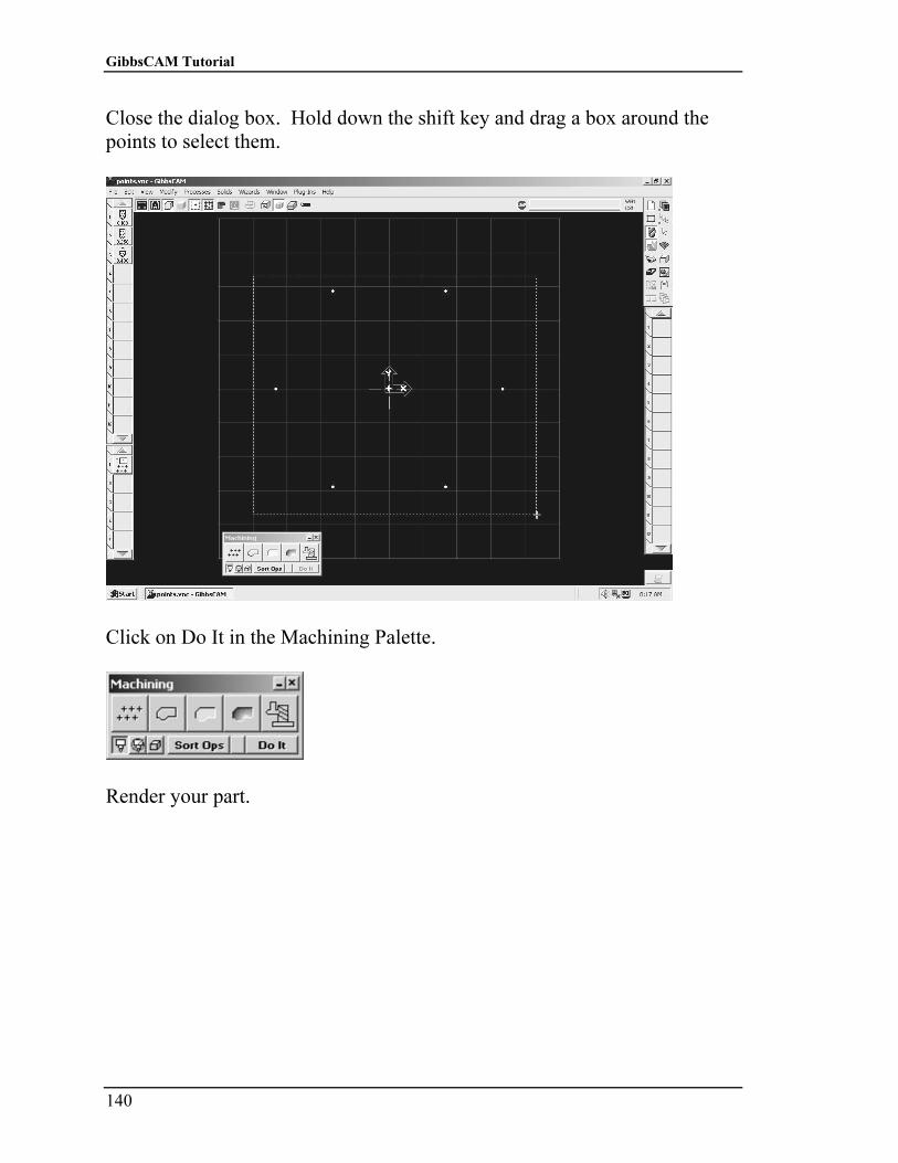
Close the dialog box. Hold down the shift key and drag a box around the
points to select them.
Click on Do It in the Machining Palette.
Render your part.
Copyrighted Material
Copyrighted
Material
Copyrighted Material
Copyrighted
Material
Drilling
141
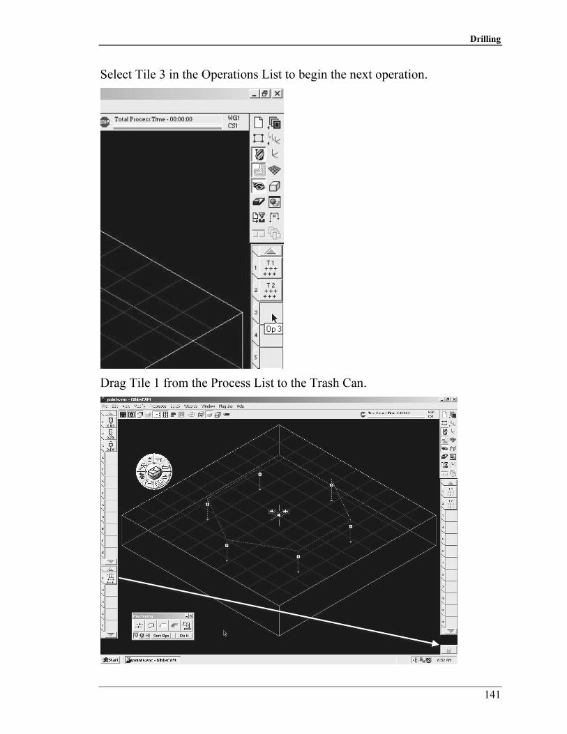
Select Tile 3 in the Operations List to begin the next operation.
Drag Tile 1 from the Process List to the Trash Can.
Copyrighted Material
Copyrighted
Material
Copyrighted Material
Copyrighted
Material
GibbsCAM Tutorial
142
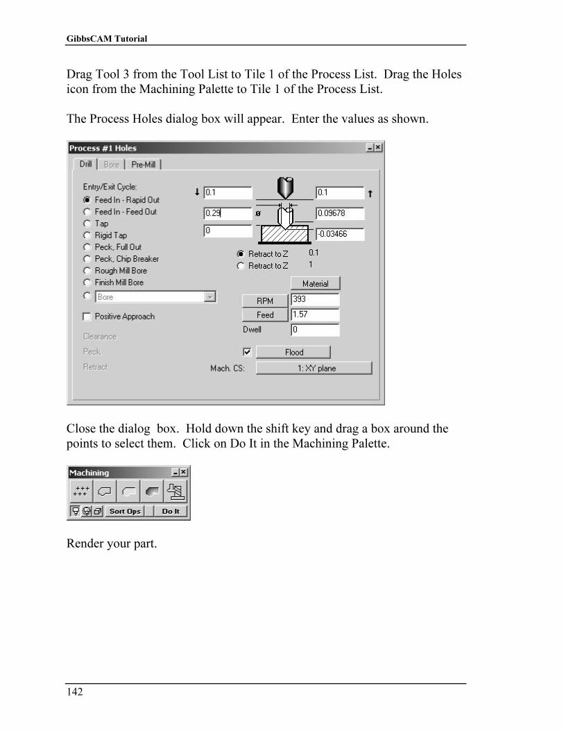
Drag Tool 3 from the Tool List to Tile 1 of the Process List. Drag the Holes
icon from the Machining Palette to Tile 1 of the Process List.
The Process Holes dialog box will appear. Enter the values as shown.
Close the dialog box. Hold down the shift key and drag a box around the
points to select them. Click on Do It in the Machining Palette.
Render your part.

Copyrighted Material
Copyrighted
Material
Copyrighted Material
Copyrighted
Material
Drilling
143
This completes the exercise. Save the file. Choose File-Save from the Main
Menu.


