1 393SYS Airport Engineering Practice Lecture 2 Development of Maintenance Programs.
43
1 393SYS 393SYS Airport Engineering Airport Engineering Practice Practice Lecture 2 Lecture 2 Development of Development of Maintenance Maintenance Programs Programs
-
date post
20-Dec-2015 -
Category
Documents
-
view
218 -
download
0
Transcript of 1 393SYS Airport Engineering Practice Lecture 2 Development of Maintenance Programs.

1
393SYS 393SYS Airport Engineering Airport Engineering
PracticePractice
Lecture 2Lecture 2Development of Development of
MaintenanceMaintenanceProgramsPrograms
2
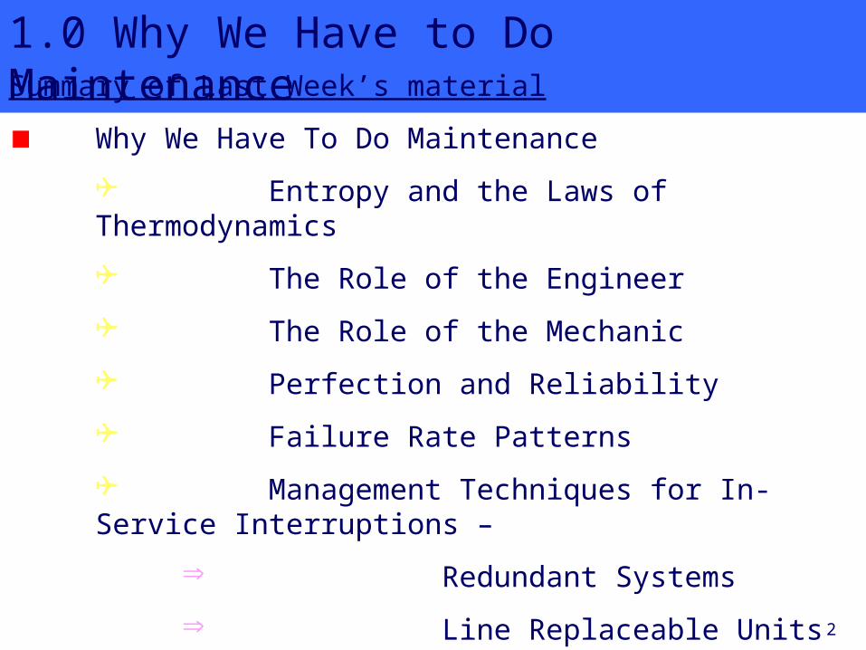
1.0 Why We Have to Do MaintenanceSummary of Last Week’s material
Why We Have To Do Maintenance
Entropy and the Laws of Thermodynamics
The Role of the Engineer
The Role of the Mechanic
Perfection and Reliability
Failure Rate Patterns
Management Techniques for In-Service Interruptions –
Redundant Systems
Line Replaceable Units
Minimum Equipment List

3
1.0 Why We Have to Do MaintenanceWhat is a component and what is a system ? A collection of components organized to accomplish a specific function or set of functions.
An assembly of various components designed to function as a whole.
A collection of interacting subsystems designed to satisfy a set of requirements.
So a system is composed of components, or smaller subsystems, and all of it is designed to provide one or more functions.
A component is the smallest part – you cannot subdivide a component.

4
1.0 Why We Have to Do Maintenance
Various Systems

5
1.0 Why We Have to Do Maintenance
UNDERSTANDING SYSTEMS
A system is a collection ofparts that interact tofunction purposefully
as a whole.
A collection ofauto parts is
NOT a system
A working carIS a system

6
1.0 Why We Have to Do Maintenance
Reliability Parameters
In last week’s tutorial, we considered the “bath tub” failure rate curve :
The question was asked, “How do you think failure rate data is obtained ?”
We now consider some reliability parameters which are in practical use in managing aircraft maintenance.
parameters - are quantities that define certain characteristics of systems

7
1.0 Why We Have to Do Maintenance
Mean Time Between Failures (MTBF)
MTBF is the average time between the failures of a component or system.
Mean Time to Repair (MTTR)
MTTR is the time taken to repair or replace a component or system.
Availability (A)
The availability of a component or system is the percentage of time when it is operational :
MTBFA = ---------------------- x 100% MTBF + MTTR

8
1.0 Why We Have to Do Maintenance
Example
During a period of 100,000 flight hours an avionics component on a commercial aircraft failed 50 times. In this case,
MTBF = 200,000 / 50 = 4,000 hours
Assume the component can only be replaced after an interval of time equal to 1 cycle, and that the average cycle time for this aircraft is 2 hours. Then, the MTTR = 2 hours and the availability is -
MTBF 4000 hoursA = ---------------------- x 100% = ------------------------- x 100% MTBF + MTTR 4000 hours + 2 hours
= 99.95% =======

9
1.0 Why We Have to Do Maintenance
Reliability
Component reliability is the probability of no failure over a specified period of time.
This reliability (R(t)) is given in terms of the failure rate (λ) which is the number of component failures per unit time :
R(t) = exp(-λt)
In this formula, the failure rate, λ, is assumed to be constant with the age of the component.
Note : In general, failure rate is not constant –

10
1.0 Why We Have to Do Maintenance
Example
Logs of aircraft equipment failures reveal that a particular aircraft component has experienced 40 failures in 100,000 hours of use. The failure rate may then be calculated as follows :
λ = 40/100,000 = 0.0004
For a 2 hour flight, t = 2 and the reliability then becomes –
R(t) = exp(-λt) ≈ 1 – λt [when λt is less than 0.001]
So R(t) = 1 – 0.0004 x 2 = 1 – 0.0008 = 0.9992
or, expressed as a percentage,
R%(t) = 0.9992 x 100% = 99.92%

11
1.0 Why We Have to Do MaintenanceSystem Reliability
The reliability of a system composed of two components, X and Y, is given by -
Rsystem = RX x RY
where it is assumed that the system fails if either item fails, and that failures are statistically independent.
An example of the type of system where this would occur is represented as follows -
Component X Component Y
This is referred to as a “series system” because both components operate in series and if one fails, the whole system fails.
12
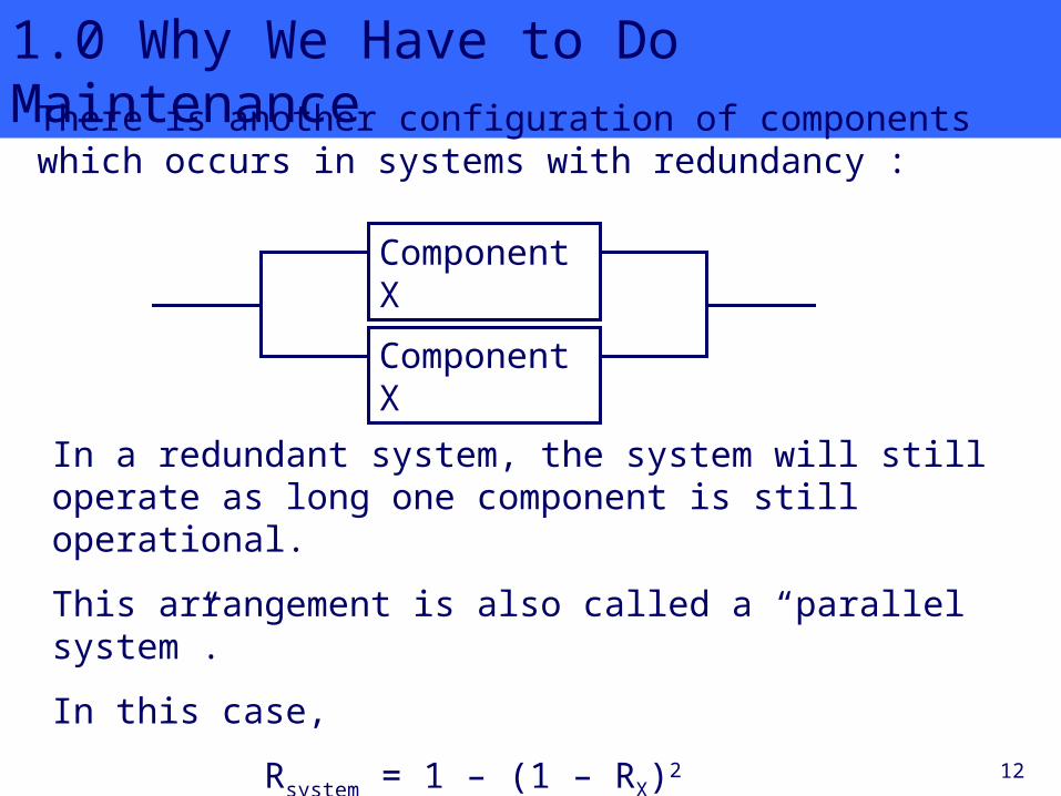
1.0 Why We Have to Do MaintenanceThere is another configuration of components which occurs in systems with redundancy :
Component X
Component X
In a redundant system, the system will still operate as long one component is still operational.
This arrangement is also called a “parallel system”.
In this case,
Rsystem = 1 – (1 – RX)2

13
1.0 Why We Have to Do MaintenanceLets compare the reliability of a system with a single component with reliability of a series system and the reliability of a parallel system :
Component X
Component X Rsystem = 1 – (1 – RX)2
= 1 – (1 – 0.9992)2
= 0.99999936
Component X RX = R = 0.9992
Component X Component Y
Rsystem = RX x RX = 0.9992 x 0.9992 = 0.9984
14
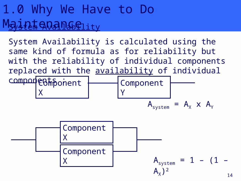
1.0 Why We Have to Do MaintenanceSystem Availability
System Availability is calculated using the same kind of formula as for reliability but with the reliability of individual components replaced with the availability of individual components :
Component X Component Y
Component X
Component X
Asystem = AX x AY
Asystem = 1 – (1 – AX)2
15
1.0 Why We Have to Do Maintenance
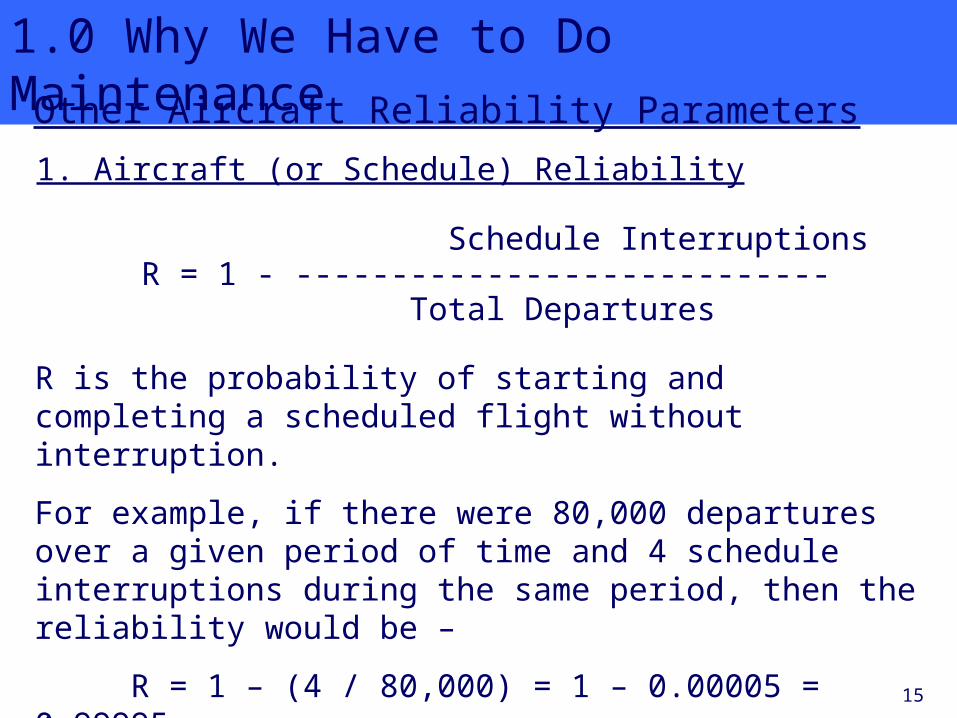
Other Aircraft Reliability Parameters
Schedule InterruptionsR = 1 - ----------------------------
Total Departures
1. Aircraft (or Schedule) Reliability
R is the probability of starting and completing a scheduled flight without interruption.
For example, if there were 80,000 departures over a given period of time and 4 schedule interruptions during the same period, then the reliability would be –
R = 1 – (4 / 80,000) = 1 – 0.00005 = 0.99995

16
1.0 Why We Have to Do Maintenance
2. Dispatch Reliability
R = 1 – ((delays + cancellations) / total departures)
This is the probability of departing on time.
3. En Route Reliability
R = 1 - ((air turnbacks + ground turnbacks + diversions) / total departures)
where an air turnback occurs after take-off, and a ground turnback occurs before take-off.

17
2.0
Development of Maintenance
Programs

18
2.0 Development of Maintenance ProgramsIntroduction
We have seen in the first lecture that components and systems fail in different ways and at different rates.
This results in a requirement for unscheduled maintenance that is somewhat erratic and uncertain.
There are periods high workloads and periods with no work – these have to be managed to smooth out the workload and
stabilize the manpower requirements.
The maintenance programs currently in use in commercial aviation were developed by the aviation industry using two diffeent approaches :
the process-oriented approach, and
the task-oriented approach

19
2.0 Development of Maintenance ProgramsThe Process-Oriented Approach
This uses three primary maintenance processes to accomplish the scheduled maintenance actions :
1. Hard-Time (HT)Used for components or systems that have definite life limits. Item is
removed at a predetermined interval, usually specified in either flight hours or flight cycles.
2. On-Condition (OC)Used for components or systems that have detectable wear out
periods. Item will be checked at specific intervals (in hours, cycles, or calendar time) to determine its remaining serviceability.
3. Condition Monitoring (CM)Used to monitor systems and components that cannot utilize either HT
or OC processes. Involves monitoring of failure rates, removal rates, etc. to facilitate maintenance planning
20
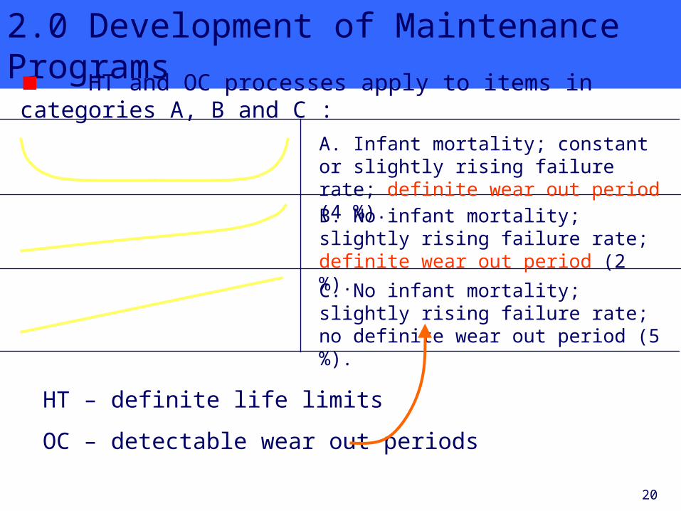
2.0 Development of Maintenance Programs
HT and OC processes apply to items in categories A, B and C :
A. Infant mortality; constant or slightly rising failure rate; definite wear out period (4 %).
B. No infant mortality; slightly rising failure rate; definite wear out period (2 %).
C. No infant mortality; slightly rising failure rate; no definite wear out period (5 %).
HT – definite life limits
OC – detectable wear out periods

21
2.0 Development of Maintenance Programs
CM items are operated to failure and failure rates are tracked to aid in failure prediction or failure prevention efforts.
These are “operate to failure” items in categories D, E and F :
D. Increasing failure rate at outset; constant or slightly rising failure rate; no definite wear out period (7 %).
E. No infant mortality; constant failure rate throughout life; no definite wear out period (14 %).
F. Infant mortality; constant failure rate throughout life; no definite wear out period (68 %).
CM – no definite wear out period.

22
2.0 Development of Maintenance Programs
The Task-Oriented Approach
Uses predetermined maintenance tasks to avoid in-service failures.
Equipment redundancies are sometimes used to allow in-service failures to occur without adversely affecting safety and operation.
More on this approach next week.

23
2.0 Development of Maintenance ProgramsThe Maintenance Steering Group (MSG) Approach
The modern approach to aircraft maintenance started with the Boeing Company in 1968.
It coincided with the introduction of the Boeing 747 – then the largest commercial airplane.
Six industry working groups analysed aircraft –
1. structures
2. mechanical systems
3. engines and auxiliary power plants
4. electrical and avionics systems
5. flight controls and hydraulics
6. “zonal” configurations.

24
2.0 Development of Maintenance Programs
This analysis provided them with information on failure modes, failure effects and failure causes.
The approach was called “bottom up” because it looked at the components as the most likely causes of equipment
malfunction.
The purpose of the analysis was to determine which of the three processes (HT, OC or CM) would be required to repair the item and return it to service.
This resulted in the a generalized maintenance process called MSG-2 which could be applied to any aircraft, not just 747s.
The following table summarizes the steps involved.
Note that the process is sligtly different for (a) systems and components, (b) structures and (c) engines :

25
Step Number Analysis ActivitySystem/
ComponentStructure Engine
1 1 Identify the systems and their significant items.
1 Identify significant structural items.
2 Identify their functions, failure modes, and failure reliability.
2 Identify failure modes and failure effects.
2 Identify their functions, failure modes and failure effects.
3 Define scheduled mainteance tasks having potential effectiveness relative to the control of operational reliability.
3 Assess the potential effectiveness of scheduled inspections of structure.
4 4 Assess the desirability of scheduling those tasks having potential effectiveness.
4 Assess the desirability of those inspections of structure which do have potential effectiveness.
5 Determine that initial sampling thresholds were appropriate.

26
2.0 Development of Maintenance Programs
The steps in this table may be generalized as follows :
Step 1 : Identify the maintenance or structure items requiring analysis.
Step 2 : Identify the functions and failure modes associated with the item and the effect of the failure.
Step 3 : Identify those tasks which may have potential effectiveness.
Step 4 : Assess the applicability of those tasks and select those deemed necessary.
Step 5 : For structures only, evaluate initial sampling thresholds.
The following is a simplified process flow diagram for MSG-2 :

27
Does the unit’s failure affect flight safety ?
(1)
Is the failure evident to the flight crew ?
(2)
No
Is reduced resistance to
failure detectable by a maintenance
check ?
(4)Is there a
mainteance check to assure continued
function ?
(5)
Is there an adverse
relationship between the
unit’s age and reliability ?
(3)
YesYes
Yes
Hard Time
No
On Condition
Yes
On Condition
Yes
Hard Time
No
Condition Monitoring
No
No

28
2.0 Development of Maintenance Programs
E.G.: If failure of the unit is safety related (1), and there is a maintenance check available to detect a reduction in failure resistance (4), then the item in question is identified as on-condition.

29
2.0 Development of Maintenance Programs
Once the maintenance action is determined, it is then necessary to determine how often such maintenance should be done.
Available data on failure rates, removal rates, etc., are used to determine how often the maintenance should be performed.

30
2.0 Development of Maintenance Programs
Process-Oriented Maintenance
The Hard-Time Process
Hard time is a failure prevention process.
It is applied to items –
● having a direct adverse effect on safety
● subject to reliability degredation but having no possible maintenance check (e.g. rubber
components)
The item has to be removed from the vehicle and either –
● completely overhauled, or
● partial overhauled, or
● discarded
… before exceeding a pre specified life time.

31
2.0 Development of Maintenance ProgramsThis life time or interval between each removal of the item
may be specified in terms of –
● calendar time
● engine or aircraft check intervals
● operating cycles
● flight hours
If a particular component fails at X hours of operation, ideally the component would be replaced at the last scheduled
maintenance period prior to the accumulation of X hours.
This would give the airline the maximum service hours from the component and the component would never fail in
service.

32
2.0 Development of Maintenance ProgramsExamples of components which are regulated by hard time
failure prevention are –
● structural components
● landing gear
● life-limited engine parts – e.g. turbine blades

33
2.0 Development of Maintenance ProgramsExamples of components which are regulated by hard time
failure prevention are –
● mecahnical linkages
● actuators
● hydraulic pumps and
motors
● electric motors
● generators.All of these things and similar items having a definite wear out period and being safety related, will be subject to hard time maintenance regulations.

34
2.0 Development of Maintenance Programs
Actuators and Pumps

35
2.0 Development of Maintenance Programs
The On-Condition (OC) Process
With on-condition, the item is not removed periodically. Instead, it is subject to periodic inspections or tests.
The objective of the inspections or tests is to determine whether or not the item can continue in service.
If an item fails an OC check, only then is it removed for overhaul, repair, or replacement.
OC items are restricted to component / equipment / systems on which checks and tests can be applied without having to
remove the item.
These OC checks must be performed within time limits (intervals) prescribed for each OC check.

36
2.0 Development of Maintenance Programs
Examples of OC checks are as follows :
tire tread and brake linings
scheduled borescope inspections of engines
engine oil analysis
in-flight engine performance analysis (using “engine condition monitoring istruments (ECM) built into the engine)
In each of these cases, the amount of degredation can be measured and compared with establish norms to determine how much life or servicability remains.
Borescope ->

37
2.0 Development of Maintenance Programs
For an OC process to be applicable in a maintenance situation, one of the following must be true –
● the OC check must be able to ensure serviceability with reasonable probability until the next OC check, or
● a satisfactory measurement can be made of the failure predicting data
Examples :
Break wear indicator pins : the wear in these pins is compared to some reference standard or to some limit.
Control cables : Measure these for diameter, tension, and broken strands.
Linkages, control rods, pulleys, roller tracks, jack screws : measure these for wear, and or side play, or backlash.

38
2.0 Development of Maintenance Programs
Control Rods
Pulleys
Jack Screws

39
2.0 Development of Maintenance Programs
The Condition Monitoring (CM) Process
Unlike HT and OC processes, CM does not really monitor the condition of a component.
CM systems consist of data collection and data analysis procedures.
For example, a CM process may collect data on –
unscheduled removals of equipment from aircraft (i.e. due to some failure), maintenance log entries, pilot reports, workshop findings, sampling inspections, mechanical reliability reports, and other sources of maintenance data

40
2.0 Development of Maintenance Programs
The CM process is applied when neither the hard time nor the on-condition process can be applied.
CM is not a failure prevention process as are HT and OC.
CM components have to be operated to failure, and replacement of CM items is an unscheduled maintenance action.
Since CM items are operated to failure, these items must comply with the following conditions :
1. A CM item has no direct, adverse effect on safety when it fails.
2. A CM item must not have any “hidden function” (i.e. that cannot be observed by flight crew).
3. A CM item must be included in a CM program.

41
2.0 Development of Maintenance Programs
Typical CM components include – navigation equipment communications equipment lights instruments
other items where test or replacement will not predict approaching failure, nor result in improved life expectancy.
CM is frequently applied to – where redundant systems, coffee makers, lavatories, passenger entertainment systems
failure has no effect on safety or air worthiness

42
Summary
Systems, Subsystems and Components
Reliability Parameters
Development of Maintenance Programmes
The Process Oriented Approach
Hard Time
On Condition
Condition Monitoring
The Maintenance Steering Group Approach (MSG-2)
Process Oriented Maintenance
o The Hard Time Process
o The On Condition Process
o The Condition Monitoring Process
2.0 Development of Maintenance Programs

43
What you need to know for the exam ! Can you explain what is meant by a component and system ?
What are the various reliability pararmeters – MTBF, MTTR, Reliability and Availability ?
Can you calculate the reliability of a component or system given the failure rate for that component or system ?
Can you calculate the availability of a component or system given the MTBF and the MTTR ?
Can you calculate the reliability of a system given the failure rate one or more subsysyem components operating in series or parallel ?
What are the two main approaches developed by the aviation industry for developing maintenance programmes and what maintenance
processes do they use ?
Can you explain MSG-2 ?
Can you explain Process-Oriented Maintenance ?