1 3 S5 Sensorless control & Performance analysis of … · Sensorless control & Performance...
5
The Engineering Journal of Application & Scopes, Volume 1,Issue 1, March 2016 TEJAS © 2016 http://www.ij-tejas.com Sensorless control & Performance analysis of PMBLDC motor using back emf detection Sumit Nema Assistant Professor Department of Electrical Engineering College of Engineering Roorkee Roorkee, India - 247667 [email protected] Aadesh Kumar Arya Assistant Professor Department of Electrical Engineering College of Engineering Roorkee Roorkee, India – 247667 [email protected] Abstract—Thispaper presents the implementation of sensorless PMBLDC motor involving the back emf detection. Along with the back emf detection respective zero-crossing points are identified which is based on detecting the instant at which the back-EMF in the unexcited phase crosses zero. These zcp can be used for the generation of pulses for electronic commutation of inverter switches to achieve sensorless operation of permanentmagnetbrushlessDC(PMBLDC) motor. Performance analsysis is carried out in comparison with a sensored machines.The simulation model has been developed in MATLAB/SIMULINK environment. Index Terms- PermanentmagnetbrushlessDC(PMBLDC) motor,electromotiveforce(emf), voltage source inverter (VSI),zero crossing point (ZCP) I. INTRODUCTION BLDC motors from micro to large size are extensively used for applications in many types of motion control apparatus and systems as adjustable speed drives. The BLDC are typically permanent synchronousmotor,they are well driven by dc voltage. They have a commutationthatis done mainly by electronicsapplication.Someofthemanyadvantagesofabrushless dcmotorover the conventional brushed dc motors are highlightedbelow: 1. Better speed versus torquecharacteristics 2. High dynamicresponse 3. Highefficiency 4. Long operatinglife 5. High speedranges 6. Low maintenance (in terms of brushes cleaning;whichis peculiar to the brushed dcmotor). Basically PMBLDC motor drive uses one or more sensors to have positional information which results in a higher drive cost so sensorless techniques are keen desire. Fig. 1 shows basic inverter topology employed: V dc S1 S3 S5 S4 S6 S2 PMBLDC MOTOR Fig.1Inverter Topology with PMBLDC Motor’s Equivalent Circuit One of the most common methods used for inverter switching is pulse width modulation (PWM) techniques.. II. MATHEMATICAL MODELLINGOF PMBLDC MOTOR For a three phase star connected PMBLDC motor, per phase voltages (V an ,V bn ,V cn ) can be given as: v an v bn v cn = R s 1 0 0 0 1 0 0 0 1 i an i bn i cn + L M M M L M M M L p i an i bn i cn + e an e bn e cn (1) Where R s is stator phase resistance, L is stator phase inductance, M is mutual inductance between the phases, i an , i bn , i cn are stator current and v an , v bn , v cn are phase voltage of the stator’s winding and p is derivative operator. For a three phase star connected PMBLDC motor, i an + i bn + i cn = 0 (2) v an v bn v cn =R s 1 0 0 0 1 0 0 0 1 i an i bn i cn + L − M 0 0 0 L − M 0 0 0 L − M p i an i bn i cn + e an e bn e cn (3) Using Eq. (3), we can have current derivative as: p i an i bn i cn = L − M 0 0 0 L − M 0 0 0 L − M −1 v an v bn v cn − e an e bn e cn −R s 1 0 0 0 1 0 0 0 1 i an i bn i cn (4) Theelectromagnetic torques can be given as: T e = ∑ (e xn i xn )/ω r (5)
-
Upload
trinhduong -
Category
Documents
-
view
220 -
download
0
Transcript of 1 3 S5 Sensorless control & Performance analysis of … · Sensorless control & Performance...

The Engineering Journal of Application & Scopes, Volume 1,Issue 1, March 2016
TEJAS © 2016
http://www.ij-tejas.com
Sensorless control & Performance analysis of
PMBLDC motor using back emf detection
Sumit Nema Assistant Professor
Department of Electrical Engineering
College of Engineering Roorkee
Roorkee, India - 247667
Aadesh Kumar Arya Assistant Professor
Department of Electrical Engineering
College of Engineering Roorkee
Roorkee, India – 247667
Abstract—Thispaper presents the implementation of
sensorless PMBLDC motor involving the back emf detection.
Along with the back emf detection respective zero-crossing points
are identified which is based on detecting the instant at which the
back-EMF in the unexcited phase crosses zero. These zcp can be
used for the generation of pulses for electronic commutation of
inverter switches to achieve sensorless operation of
permanentmagnetbrushlessDC(PMBLDC) motor. Performance
analsysis is carried out in comparison with a sensored
machines.The simulation model has been developed in
MATLAB/SIMULINK environment.
Index Terms- PermanentmagnetbrushlessDC(PMBLDC)
motor,electromotiveforce(emf), voltage source inverter (VSI),zero
crossing point (ZCP)
I. INTRODUCTION
BLDC motors from micro to large size are extensively used
for applications in many types of motion control apparatus and
systems as adjustable speed drives.
The BLDC are typically permanent synchronousmotor,they are well driven by dc voltage. They have a commutationthatis done mainly by electronicsapplication.Someofthemanyadvantagesofabrushlessdcmotorover the conventional brushed dc motors are highlightedbelow:
1. Better speed versus torquecharacteristics
2. High dynamicresponse
3. Highefficiency
4. Long operatinglife 5. High speedranges
6. Low maintenance (in terms of brushes
cleaning;whichis peculiar to the brushed dcmotor).
Basically PMBLDC motor drive uses one or more sensors
to have positional information which results in a higher drive
cost so sensorless techniques are keen desire. Fig. 1 shows
basic inverter topology employed:
Vdc
S1 S3 S5
S4 S6S2
PMBLDC
MOTOR
Fig.1Inverter Topology with PMBLDC Motor’s Equivalent Circuit
One of the most common methods used for inverter
switching is pulse width modulation (PWM) techniques..
II. MATHEMATICAL MODELLINGOF PMBLDC MOTOR
For a three phase star connected PMBLDC motor, per phase voltages (Van,Vbn,Vcn) can be given as:
van
vbn
vcn
= Rs 100
010
001
ian
ibn
icn
+ LMM
MLM
MML p
ian
ibn
icn
+
ean
ebn
ecn
(1)
Where Rs is stator phase resistance, L is stator phase inductance, M is mutual inductance between the phases, ian, ibn, icn are stator current and van, vbn, vcn are phase voltage of the stator’s winding and p is derivative operator.
For a three phase star connected PMBLDC motor,
ian + ibn + icn = 0 (2)
van
vbn
vcn
=Rs 100
010
001
ian
ibn
icn
+ L − M
00
0L − M
0
00
L − M p
ian
ibn
icn
+
ean
ebn
ecn
(3)
Using Eq. (3), we can have current derivative as:
p
ian
ibn
icn
= L − M
00
0L − M
0
00
L − M
−1
van
vbn
vcn
−
ean
ebn
ecn
−Rs 100
010
001
ian
ibn
icn
(4)
Theelectromagnetic torques can be given as:
Te = ∑ (exn ixn )/ωr (5)

The Engineering Journal of Application & Scopes, Volume 1,Issue 1, March 2016
TEJAS © 2016
http://www.ij-tejas.com
Where𝛚r, represents the rotor speed, x represent the phase a, b
and c while n represent the neutral terminal. Since back emf is
a function of flux and rotor position, it can be expressed as:
exn = fxn θ λx ωr (6)
Where𝛌x, represents the flux linkage and fxn (𝝷) have the same
shape as of the back emf. Substituting Eq. (6) in Eq. (5), we
have:
Te = λx ∑ fxn θ ixn (7)
The equation of motion for simple system is
Jdω
dt+ Bω = Te − Tl (8)
Where, Te is electromagnetic torque, Tlis load torque, J is
motor inertia and B is damping constant.The relation between
angular position (electrical) and angular mechanical velocity is
given by:
dθe
dt=(P/2)∗ ω (9)
Eq. (1)-(9) represents the dynamic model of the PMBLDC
motor. The trapezoidal back EMF waveform and the phase
current of the PMBLDC motorareshown in the Fig.2. The
graph is presented for one complete cycle of 360 degrees.
InthismethodZCPoftheback
EMFisdetecteddirectly.FortypicaloperationofaBLDCmotor,the
phasecurrentandback-EMFshouldbealignedtogenerate the
constanttorque.ThecommutationpointcanbeestimatedbytheZC
Pofback EMF. The conducting intervalforeach phase is 120
electrical degrees. Therefore, leaving the thirdphasefloating,
only two phases conduct current at any time. The inverter
should be commutated every 60° by detecting
zerocrossingofbackEMFonthefloatingcoilofthemotor in order
to produce maximum torque,
sothatcurrentisinphasewiththebackEMF.
0˚ 30˚ 60˚ 90˚ 120˚ 150˚ 180˚ 210˚ 240˚ 270˚ 300˚ 330˚ 360˚
tea
ia
eb
ib
ic
t
t
t
t
t
ec
Fig.2 Back EMF and Phase current waveforms of PMBLDC motor
III. SIMULATION RESULTS AND ANALYSIS
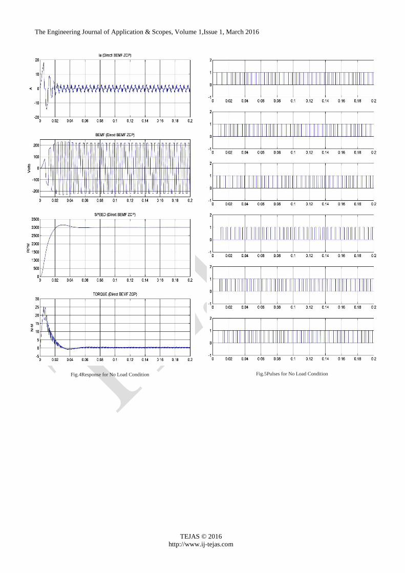
Simulation for the discussed technique has been carried out in MATLAB/SIMULINK environment and experimental model modelled as shown in Fig. 3. All the respective parameters for techniques are mentioned in appendix, Various wave-form for current, back emf, speed and torque and inverter pulses has been obtained at no load as well as on load condition having load of 3 N-m and the respective wave-form obtained are as follow:
Ref.
Speed
Speed
Controller
3 Phase VSI Inverter
ea+
-
PMBLDC
Motor
ia
te
n
Ref. Current
Pulses
A
B
C
A
B
C
N
S
ZCP DetectorPulse Decoder
m
Fig.3 Back EMF and Phase current waveforms of PMBLDC motor
The Engineering Journal of Application & Scopes, Volume 1,Issue 1, March 2016
TEJAS © 2016
http://www.ij-tejas.com
Fig.4Response for No Load Condition
Fig.5Pulses for No Load Condition

The Engineering Journal of Application & Scopes, Volume 1,Issue 1, March 2016
TEJAS © 2016
http://www.ij-tejas.com
Fig.6Response for Load Condition
Fig.7 Pulses for Load Condition

The Engineering Journal of Application & Scopes, Volume 1,Issue 1, March 2016
TEJAS © 2016
http://www.ij-tejas.com
Based on various results following analysis has been made:
TABLE I. ANALYSIS FOR SPEED RESPONSE
No Load
Method
Settling
Time
(s)
Maximum
transient
Overshoot
(r/min)
Speed Ripple
(Peak to Peak)
under steady
state
(r/min)
Physical
Condition
BEMF ZCD 0.07 3096
3
(2999-
3002)
Excellent
Response
and stable
TABLE II. ANALYSIS FOR SPEED RESPONSE
On Load
Method
Settling
Time
(s)
Maximum
transient
Overshoot
(r/min)
Speed Ripple
(Peak to Peak)
under steady
state
(r/min)
Physical
Condition
BEMF ZCD 0.07 3096
3
(2999-
3002)
Excellent
Response
and stable
IV. CONCLUSION
The aim of the work was to introduce sensorless operation
ofPMBLDC motor. Based on discussed procedure, simulation
model has been developed and response is shown in different
figures along with inverter pulses for no load as well as on
load operation. With respect to various results conclusion can
be drawn that at no load as well as on load condition Back
EMF approch implies excellent and same response as
compared to sensored machine.
APPENDIX
A. PMBLDC Motor Specifications[16]:
Power : 1 Kw
Speed : 3000 rpm
Vdc : 500V
Stator phase resistance Rs : 2.875 ohm
Stator phase inductance Ls : 0.0085 h
Flux linkage : 0.175 V.s
Voltage Constant : 146.6077
Torque Constant : 0.49
Back EMF flat area (degrees) : 120
Inertia, J : 0.00012 kg.m2
Friction factor F : 0.001 N.m.s
Pole Pairs P : 4
Back EMF waveform : Trapezoidal
Mechanical input : Tm
B. PI-Controller parameters:
Proportional gain, Kp : 0.13
Integral gain, Ki : 16.61
C. Three-PhaseInverter:
Input DC Voltage : 500 V
No. of switches : 6
REFERENCES
[1] R. Krishnan, Electric Motor Drives: Modeling,Analysis and Control, Pearson Education, New Delhi,2001.
[2] G. K. Dubey, “Power Semiconductor ControlledDrives”, Prentice Hall, New Jersey,1989.
[3] T. J. E. Miller, Brushless Permanent Magnet andReluctance Motor Drive, Clarendon Press, oxford,1989
[4] R. Somanatham, P. V. N. Prasad and A. D. Rajkumar, “Modeling and Simulation of Sensor less Control of PMBLDC Motor Using Zero-Crossing Back E.M.F Detection”, International Symposium on Power Electronics, Electrical Drives, Automation and Motion (SPEEDAM), pp. 984 – 989,2006.
[5] Yen-Shin Lai and Yong-Kai Lin, “Novel Back-EMF Detection Technique of Brushless DC Motor Drives for Wide Range Control Without Using Current and Position Sensors”, IEEE Trans. Power Electronics, vol. 23, no. 2, pp. 934 – 940, 2008.
[6] K. S. Rama Rao, Nagadeven and Soib Taib,“Sensorless Control of a BLDC Motor with Back EMF Detection Method using DSPIC”, 2ndIEEE International Conf. Power and Energy (PECon 08), pp. 243 – 248, Dec. 2008.
[7] Yen-Shin Lai and Yong-Kai Lin, “Back-EMF Detection Technique of Brushless DC Motor Drives for Wide Range Control”, IEEE Trans. Power Electronics, vol. 23, no. 2, pp. 934 – 940, 2008.
[8] Haifeng Lu, Lei Zhang, and Wenlong Qu,“A New Torque Control Method for Torque Ripple Minimization of BLDC Motors With Un-Ideal Back EMF”, IEEE Trans. Power Electronics, vol. 23, no. 2, pp. 950 – 958, March 2008.
[9] B. Singh and S. Singh, “State of the Art on Permanent Magnet Brushless DC Motor Drives”, Journal of Power Electronics, vol.. 9, no. 1, January 2009
[10] Tae-Hyung Kim and Mehrdad Ehsani, “Sensorless Control of the BLDC Motors From Near-Zero to High Speeds”,IEEE Trans. Power Electronics, vol. 19, no. 6, November 2004.
[11] S. Singh and B. Singh,“Power Quality Improvement of PMBLDCM Driven Air-conditioner usingaSingle-Stage PFC Boost Bridge Converter”, Annual IEEE India Conf. (INDICON), 2009.
[12] Paul P. Acarnley and John F. Watson, “Modeling of BLDC Motor with Ideal Back EMF for Automotive Applications”, IEEE Trans. Industrial Electronics, vol. 53, no. 2, pp. 352-362, April, 2006.
[13] Sha Lin and Du Qifei, “Review of Position-Sensorless Operation of Brushless Permanent-Magnet Machines”, International Conf. Control, Automation and Systems Engineering (CASE), pp. 1–3, 2011.
[14] Sha Lin and Du Qifei, “Sensorless Control Technique for BLDCM”, International Conf. Control, Automation and Systems Engineering (CASE), pp. 1–3, 2011.
[15] B. S. Parihar and S. Sharma, “Performance Analysis of Improved Power Quality Converter Fed PMBLDC Motor Drive”, IEEE Students Conf. Electrical, Electronics and Computer Science (SCEECS), 2014
[16] Matlab 7.10.0 (R2010a) Mathwork Ink.
[17] Microchip AN885 “Brushless DC (BLDC) Motor Fundamentals” Microchip Technology Inc.