1 3 1 4 1 PLANNING GUIDE FOR - Kone planning guide_DEC_2016_E… · Configuring your escalator or...
100
8201 KONE Corporation www.kone.co.uk This publication is for general informational purposes only and we reserve the right at any time to alter the product design and specifications. No statement this publication contains shall be construed as a warranty or condition, express or implied, as to any product, its fitness for any particular purpose, merchantability, quality or representation of the terms of any purchase agreement. Minor differences between printed and actual colors may exist. KONE MonoSpace ® , KONE EcoDisc ® , KONE Care ® and People Flow ® are registered trademarks of KONE Corporation. Copyright © 2016 KONE Corporation. KONE provides innovative and eco-efficient solutions for lifts, escalators, automatic building doors and the systems that integrate them with today’s intelligent buildings. We support our customers every step of the way; from design, manufacturing and installation to maintenance and modernisation. KONE is a global leader in helping our customers manage the smooth flow of people and goods throughout their buildings. Our commitment to customers is present in all KONE solutions. This makes us a reliable partner throughout the life cycle of the building. We challenge the conventional wisdom of the industry. We are fast, flexible, and we have a well-deserved reputation as a technology leader, with such innovations as KONE MonoSpace ® , KONE NanoSpace ™ and KONE UltraRope ® . KONE employs close to 50,000 dedicated experts to serve you globally and locally.
Transcript of 1 3 1 4 1 PLANNING GUIDE FOR - Kone planning guide_DEC_2016_E… · Configuring your escalator or...
8201
KONE Corporation
www.kone.co.uk
This publication is for general informational purposes only and we reserve the right at any time to alter the product design and specifications. No statement this publication contains shall be construed as a warranty or condition, express or implied, as to any product, its fitness for any particular purpose, merchantability, quality or representation of the terms of any purchase agreement. Minor differences between printed and actual colors may exist. KONE MonoSpace®, KONE EcoDisc®, KONE Care® and People Flow® are registered trademarks of KONE Corporation. Copyright © 2016 KONE Corporation.
KONE provides innovative and eco-efficient
solutions for lifts, escalators, automatic building
doors and the systems that integrate
them with today’s intelligent buildings.
We support our customers every step of the way;
from design, manufacturing and installation
to maintenance and modernisation. KONE
is a global leader in helping our customers
manage the smooth flow of people and
goods throughout their buildings.
Our commitment to customers is present in
all KONE solutions. This makes us a reliable
partner throughout the life cycle of the building.
We challenge the conventional wisdom of
the industry. We are fast, flexible, and we have
a well-deserved reputation as a technology leader,
with such innovations as KONE MonoSpace®,
KONE NanoSpace™ and KONE UltraRope®.
KONE employs close to 50,000 dedicated
experts to serve you globally and locally.
© KONE Planning Guide for Escalators & Autowalks 1
1
1
1
1
1
1
1
1
1
1
1
2
3
4
5
6
7
8
9
10
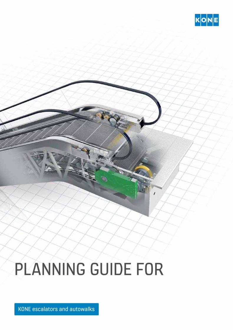
PLANNING GUIDE FOR
KONE escalators and autowalks
KONE escalators and autowalks
2
3
4 © KONE Planning Guide for Escalators & Autowalks
1. Welcome to this Planning Guide
2. How to use this Planning Guide
Designing your new project ........................................................................................................................................................................................9
3. An introduction to escalators and autowalks
3.1 Definitions and components ......................................................................................................................................................................10
3.2 The main safety code to consider ........................................................................................................................................................12
4. Optimising the People Flow™
within the building
4.1 Analysing People Flow™ ....................................................................................................................................................................................15
4.2 Calculating traffic capacity............................................................................................................................................................................16
Case 1: Shopping centre ..................................................................................................................................................................................................19
Case 2: 24h metro station .............................................................................................................................................................................................21
4.3 Understanding your building segment ........................................................................................................................................24
4.4 Deciding how many escalators and/or autowalks are needed....................................................................26
4.5 Locating your escalators and autowalks – indoors or outdoors? .............................................................29
4.6 Arranging your escalators or inclined autowalks in the building ............................................................32
5. Configuring your escalator or autowalk
5.1 Load profile ........................................................................................................................................................................................................................40
5.2 Energy consumption ..............................................................................................................................................................................................43
5.3 Step width .............................................................................................................................................................................................................................46
5.4 Nominal speed .............................................................................................................................................................................................................48
5.5 Inclination of escalators ....................................................................................................................................................................................50
5.6 Inclination of autowalks .....................................................................................................................................................................................51
5.7 Horizontal (level) steps/pallets .................................................................................................................................................................52
5.8 Vertical rise (travel height) .............................................................................................................................................................................54
5.9 Transition radii ................................................................................................................................................................................................................55
5.10 Operational modes .................................................................................................................................................................................................56
5.11 Type of balustrade .....................................................................................................................................................................................................58
5.12 Balustrade height ......................................................................................................................................................................................................60
6. Construction considerations
6.1 Passenger circulation area ..............................................................................................................................................................................64
6.2 Minimum handrail and headroom clearance ....................................................................................................................65
6.3 Protective barriers ....................................................................................................................................................................................................66
TAbLE OF cONTENTs
© KONE Planning Guide for Escalators & Autowalks 5
6.4 Head guards .....................................................................................................................................................................................................................68
6.5 Customer railings ......................................................................................................................................................................................................69
7. Preparing the site
7.1 The 6 Site Absolutes ................................................................................................................................................................................................74
7.2 Mounting locations ..................................................................................................................................................................................................75
7.3 Intermediate truss support ............................................................................................................................................................................76
7.4 Measurements prior to installation ....................................................................................................................................................77
7.5 Electrical requirements ......................................................................................................................................................................................78
7.6 Sprinkler system ..........................................................................................................................................................................................................78
7.7 Preparing to unload the escalator .......................................................................................................................................................79
7.8 Unloading the escalator ...................................................................................................................................................................................79
8. Installing the escalator or autowalk
8.1 Installation in one complete section ..............................................................................................................................................84
8.2 Installation through the building in one complete section .............................................................................85
8.3 Installation through the building in two or more
sections due to site access restrictions ..........................................................................................................................................86
8.4 Site access headroom requirements .................................................................................................................................................86
8.5 Lifting points and lifting frames ............................................................................................................................................................88
8.6 Protection of escalators and autowalks following installation .....................................................................89
9. Escalator and autowalk delivery process
10. Appendix
10.1 What is changing with EN 115-1 ............................................................................................................................................................94
10.2 Capacity ...................................................................................................................................................................................................................................94
10.3 Equipment.............................................................................................................................................................................................................................94
10.4 Site Conditions................................................................................................................................................................................................................95
10.5 Use of trolleys and shopping carts .....................................................................................................................................................95
6 © KONE Planning Guide for Escalators & Autowalks
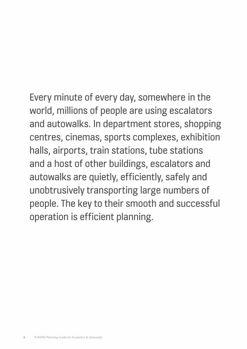
Every minute of every day, somewhere in the world, millions of people are using escalators and autowalks. In department stores, shopping centres, cinemas, sports complexes, exhibition halls, airports, train stations, tube stations and a host of other buildings, escalators and autowalks are quietly, efficiently, safely and unobtrusively transporting large numbers of people. The key to their smooth and successful operation is efficient planning.
© KONE Planning Guide for Escalators & Autowalks 7
11
Our objective is to deliver a performance edge to our customers by creating the best user experience with innovative People Flow™ solutions in the fast developing urban environment. This allows people to move around smoothly, safely and eco-efficiently in and between buildings.
For decades KONE has been providing industry-leading escalators and autowalks and we are one of the global leaders in the industry. This Planning Guide demonstrates our vast experience and expertise in this area. It is a clear, easy-to-understand and comprehensive guide to all the main process stages, from initial project planning to final commissioning.
It will help you select the correct solution for each specific application, and recommend ways to optimise the People Flow™ within your building. It will also help you understand the relevant building regulations and the European escalator and autowalk safety code.
In short, this Planning Guide will be your companion in each and every project you are involved with. I hope you find it helpful, and I wish you a successful escalator or autowalk project. Where you still have questions, please contact your local KONE sales representative, who will be delighted to give you the necessary support.
1. WELcOmE TO ThIs PLANNING GUIDE
8 © KONE Planning Guide for Escalators & Autowalks
There is no set method for using this Planning Guide. You can flick through the table of contents and quickly access the relevant information you need. The initial chapters deal with an introduction to escalators and autowalks and how to optimise people flow within your building. The guide then takes you through how to configure your solution and addresses key construction considerations. We also explain how to install the escalator or autowalk and look at some of the most pertinent changes to the EN 115-1 code.
At the end of the Planning Guide are lists of figures and tables. Again, these are added so you can quickly and easily access the figures and tables you need. For more product-specific information you may look at the accompanying product vs. segment matrix. This will allow you to see which KONE products we recommend for certain segments, such as public transportation, airport, retail, office, hotel, medical or leisure.
Based on our recommendations you can then look at the appropriate product-specific module to analyse the technical specifications of the product. You will immediately be able to see which product will best suit your particular project.
InfoPack™
The InfoPack™ is a memory stick that contains the complete Planning Guide in easy to read electronic format. This makes it easier for you to take the information with you to meetings, to project it on a screen, or to use as appropriate. The latest version of the Planning Guide can be downloaded directly from the InfoPack which is linked to KONE.co.uk.
KONE.co.uk
The Planning Guide can also be accessed from the KONE.co.uk website.
2. hOW TO UsE ThIs PLANNING GUIDE
© KONE Planning Guide for Escalators & Autowalks 9
12
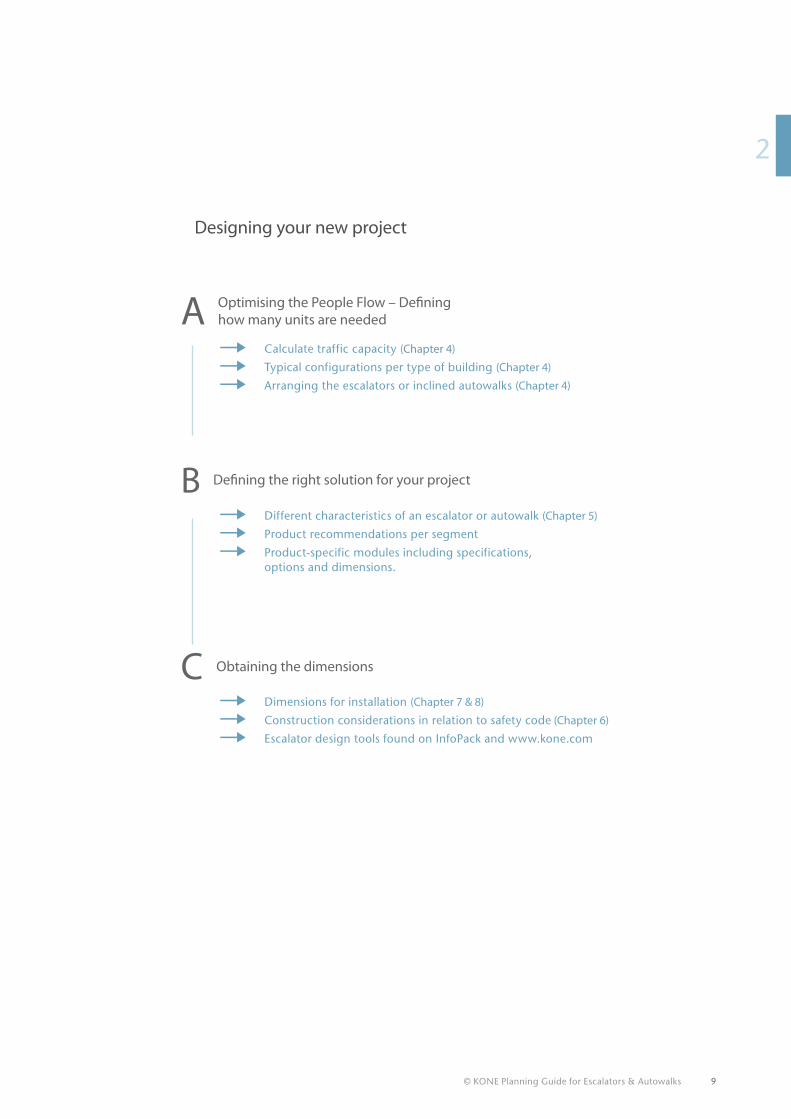
Designing your new project
→→ Calculate traffic capacity (Chapter 4)
→→ Typical configurations per type of building (Chapter 4)
→→ Arranging the escalators or inclined autowalks (Chapter 4)
A Optimising the People Flow – Defining how many units are needed
B Defining the right solution for your project
→→ Different characteristics of an escalator or autowalk (Chapter 5)
→→ Product recommendations per segment
→→ Product-specific modules including specifications, options and dimensions.
C Obtaining the dimensions
→→ Dimensions for installation (Chapter 7 & 8)
→→ Construction considerations in relation to safety code (Chapter 6)
→→ Escalator design tools found on InfoPack and www.kone.com
10 © KONE Planning Guide for Escalators & Autowalks
3. AN INTRODUcTION TO EscALATORs AND AUTOWALKs
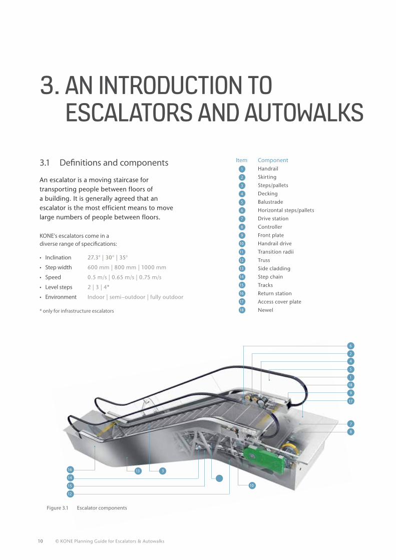
KONE's escalators come in a diverse range of specifications:
• Inclination 27.3° | 30° | 35°
• Step width 600 mm | 800 mm | 1000 mm
• Speed 0.5 m/s | 0.65 m/s | 0.75 m/s
• Level steps 2 | 3 | 4*
• Environment Indoor | semi–outdoor | fully outdoor
* only for infrastructure escalators 18
17
15
14
13
12
11
10
9
8
7
6
5
4
3
2
1
16
Item Component Handrail
Skirting
Steps/pallets
Decking
Balustrade
Horizontal steps/pallets
Drive station
Controller
Front plate
Handrail drive
Transition radii
Truss
Side cladding
Step chain
Tracks
Return station
Access cover plate
Newel
An escalator is a moving staircase for transporting people between floors of a building. It is generally agreed that an escalator is the most efficient means to move large numbers of people between floors.
3.1 Definitions and components
Figure 3.1 Escalator components
15
14
12
16 13 3
18
17
10
9
8
7
6
2
4
5
1
© KONE Planning Guide for Escalators & Autowalks 11
13
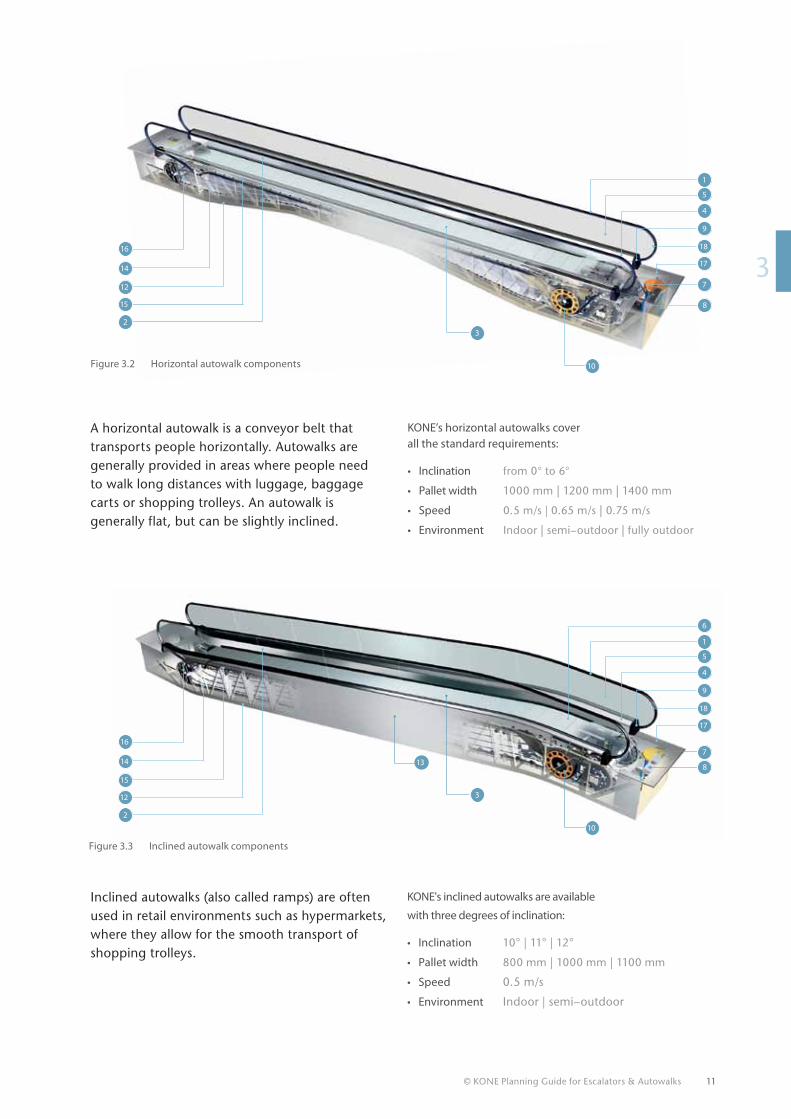
A horizontal autowalk is a conveyor belt that transports people horizontally. Autowalks are generally provided in areas where people need to walk long distances with luggage, baggage carts or shopping trolleys. An autowalk is generally flat, but can be slightly inclined.
Inclined autowalks (also called ramps) are often used in retail environments such as hypermarkets, where they allow for the smooth transport of shopping trolleys.
KONE’s horizontal autowalks cover all the standard requirements:
• Inclination from 0° to 6°
• Pallet width 1000 mm | 1200 mm | 1400 mm
• Speed 0.5 m/s | 0.65 m/s | 0.75 m/s
• Environment Indoor | semi–outdoor | fully outdoor
KONE's inclined autowalks are available
with three degrees of inclination:
• Inclination 10° | 11° | 12°
• Pallet width 800 mm | 1000 mm | 1100 mm
• Speed 0.5 m/s
• Environment Indoor | semi–outdoor
Figure 3.3 Inclined autowalk components
Figure 3.2 Horizontal autowalk components
12
14
15
2
16
15
14
12
2
16
18
17
13
10
9
8
7
6
5
4
3
1
18
17
10
9
8
7
5
4
3
1
12 © KONE Planning Guide for Escalators & Autowalks
* EN 115-1 is mandatory in Austria, Belgium, Bulgaria, Cyprus, Czech Republic, Denmark, Estonia, Finland, France, Germany, Greece, Hungary, Iceland, Ireland, Italy, Latvia, Lithuania, Luxembourg, Malta, Netherlands, Norway, Poland, Portugal, Romania, Slovakia, Slovenia, Spain, Sweden, Switzerland and United Kingdom.
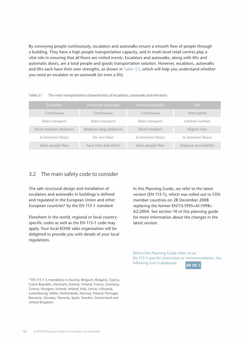
Table 3.1 The main transportation characteristics of escalators, autowalks and elevators
Escalators Horizontal autowalks Inclined autowalks Lifts
Continuous Continuous Continuous Interrupted
Mass transport Mass transport Mass transport Limited number
Short-medium distances Medium-long distances Short-medium Higher rises
In between floors On one floor In between floors In between floors
Steer people flow Save time and effort Steer people flow Improve accessibility
The safe structural design and installation of escalators and autowalks in buildings is defined and regulated in the European Union and other European countries* by the EN 115-1 standard. Elsewhere in the world, regional or local country-specific codes as well as the EN 115-1 code may apply. Your local KONE sales organisation will be delighted to provide you with details of your local regulations.
Where this Planning Guide refers to an EN 115-1-specific instruction or recommendation, the following icon is displayed:
3.2 The main safety code to consider
By conveying people continuously, escalators and autowalks ensure a smooth flow of people through a building. They have a high people transportation capacity, and in multi-level retail centres play a vital role in ensuring that all floors are visited evenly. Escalators and autowalks, along with lifts and automatic doors, are a total people and goods transportation solution. However, escalators, autowalks and lifts each have their own strengths, as shown in Table 3.1, which will help you understand whether you need an escalator or an autowalk (or even a lift).
In this Planning Guide, we refer to the latest version (EN 115-1), which was rolled out to CEN member countries on 28 December 2008 replacing the former EN115:1995+A1:1998+ A2:2004. See section 10 of this planning guide for more information about the changes in the latest version.
13
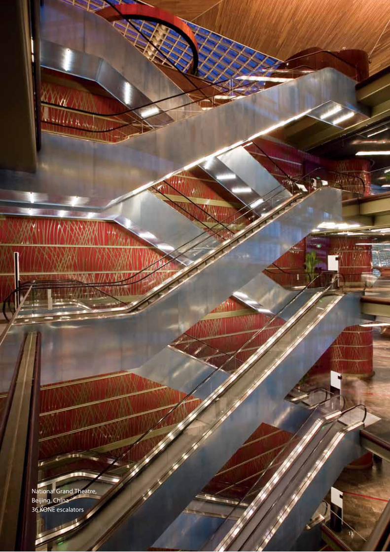
National Grand Theatre, Beijing, China 36 KONE escalators
14 © KONE Planning Guide for Escalators & Autowalks
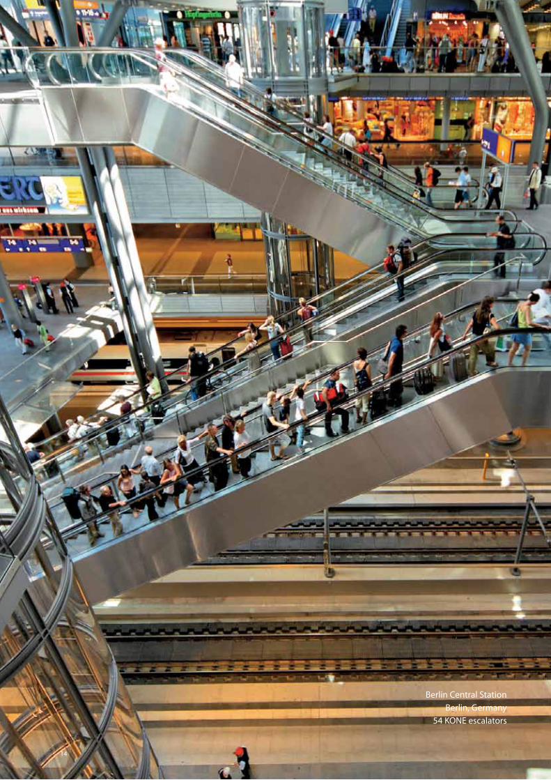
Berlin Central Station Berlin, Germany
54 KONE escalators
14
© KONE Planning Guide for Escalators & Autowalks 15
14
4. OPTImIsING ThE PEOPLE FLOW™ WIThIN ThE bUILDING
4.1 Analysing People Flow™
People flow varies immensely in each type of building. Understanding people flow will help you select the correct type and number of escalators and autowalks, and configure them correctly for the building.
The easiest way to understand people flow is to look at two buildings where the people flow is widely different: a multi-floor shopping centre and a 24h metro station (see the case studies later in this chapter).
What is People Flow™?
By 2030 there will be two billion more people living in cities than there are now, making the urban population almost five billion. To support this influx of people into cities, the importance of building comfortable and efficient urban environments is paramount. At the same time, increased environmental awareness is demanding more eco-efficient and environmentally-friendly solutions. And let’s not forget that an aging population requires more focus on better accessibility, safety and security.
KONE is dedicated to the development of sustainable urban living, and is committed to making urban environments better places for people to live in.
Our vision is to deliver the best People Flow™ experience. By People Flow we mean:
• Moving people smoothly, safely, comfortably and without waiting in and between buildings
• Ensuring high quality accessibility for everyone.
Furthermore, People Flow gives us direction for developing our offering to meet our customers’ needs, and enables us to credibly sell, deliver and maintain complete solutions instead of just products.
16 © KONE Planning Guide for Escalators & Autowalks
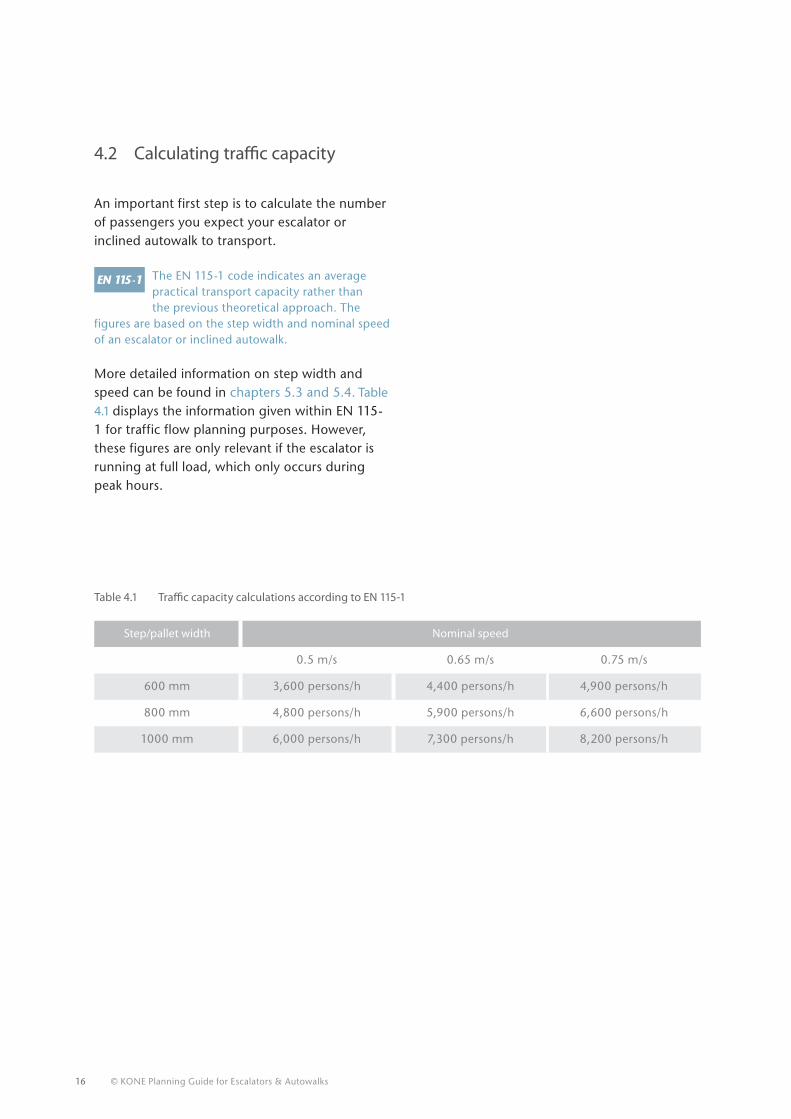
Step/pallet width Nominal speed
0.5 m/s 0.65 m/s 0.75 m/s
600 mm 3,600 persons/h 4,400 persons/h 4,900 persons/h
800 mm 4,800 persons/h 5,900 persons/h 6,600 persons/h
1000 mm 6,000 persons/h 7,300 persons/h 8,200 persons/h
4.2 Calculating traffic capacity
An important first step is to calculate the number of passengers you expect your escalator or inclined autowalk to transport.
The EN 115-1 code indicates an average practical transport capacity rather thanthe previous theoretical approach. The
figures are based on the step width and nominal speed of an escalator or inclined autowalk.
More detailed information on step width and speed can be found in chapters 5.3 and 5.4. Table 4.1 displays the information given within EN 115-1 for traffic flow planning purposes. However, these figures are only relevant if the escalator is running at full load, which only occurs during peak hours.
Table 4.1 Traffic capacity calculations according to EN 115-1
© KONE Planning Guide for Escalators & Autowalks 17
41
When carrying out such traffic capacity calculations for your projects, please take into consideration that some other important factors come into play which may influence your traffic capacity:
• Every step is not likely to be 100% occupied
• In reality, many passengers leave at least one clear step between themselves and the passenger in front
• As the speed of the step band increases, step occupancy decreases, because passengers hesitate longer before boarding.
Consider a metro station escalator, with a speed of 0.65 m/s and a 1000 mm step
width, in continuous operation in both directions for a period of 20 hours a day, 7 days a week and 365 days per year. If it was running at full load for the whole of its 20 hours of operation, its traffic capacity would be:
20 hours x 7,300 persons/hour = 146,000 persons per day
In reality, during its 20 hours of operation per day, its passenger load will vary as follows:
40% full load (2,920 persons) for 3 hours = 8,760 persons
100% full load (7,300 persons) for 2 hours = 14,600 persons
50% full load (3,650 persons) for 8 hours = 29,200 persons
100% full load (7,300 persons) for 2 hours = 14,600 persons
40% full load (2,920 persons) for 5 hours = 14,600 persons
This makes a total of 81,760 persons carried over its 20 hours of daily operation at 61.2% equivalent load profile.
In case of shopping centres one should note that the use of shopping trolleys and baggage carts will reduce capacity by approximately 80%. Increasing the pallet width of horizontal autowalks beyond 1000 mm will not necessarily increase capacity as users need to hold the handrail. The additional width is principally to enable the use of shopping trolleys and baggage carts.
The conclusion therefore is that traffic capacity calculations are complicated as they are affected by a number of criteria. KONE experts are available to help you calculate the exact traffic capacity of your escalator or autowalk, to ensure it perfectly matches the requirements of the building.
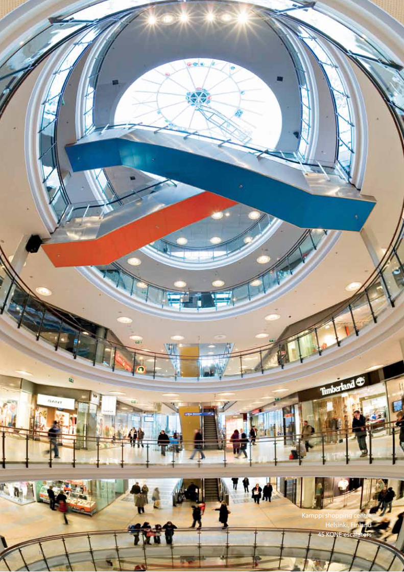
Kamppi shopping centre Helsinki, Finland
45 KONE escalators
18
© KONE Planning Guide for Escalators & Autowalks 19
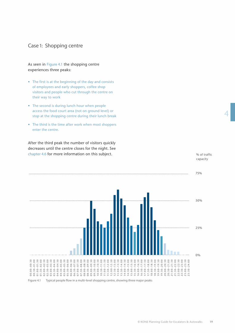
41
Figure 4.1 Typical people flow in a multi-level shopping centre, showing three major peaks
Case 1: Shopping centre
As seen in Figure 4.1 the shopping centre experiences three peaks:
• The first is at the beginning of the day and consists of employees and early shoppers, coffee shop visitors and people who cut through the centre on their way to work
• The second is during lunch hour when people access the food court area (not on ground level) or stop at the shopping centre during their lunch break
• The third is the time after work when most shoppers enter the centre.
After the third peak the number of visitors quickly decreases until the centre closes for the night. See chapter 4.6 for more information on this subject.
75%
50%
25%
0%
00
:00
–0
0:3
00
0:3
0–
01
:00
01
:00
–0
1:3
00
1:3
0–
02
:00
02
:00
–0
2:3
00
2:3
0–
03
:00
03
:00
–0
3:3
00
3:3
0–
04
:00
04
:00
–0
4:3
00
4:3
0–
05
:00
05
:00
–0
5:3
00
5:3
0–
06
:00
06
:00
–0
6:3
00
6:3
0–
07
:00
07
:00
–0
7:3
00
7:3
0–
08
:00
08
:00
–0
8:3
00
8:3
0–
09
:00
09
:00
–0
9:3
00
9:3
0–
10
:00
10
:00
–1
0:3
01
0:3
0–
11
:00
11
:00
–1
1:3
01
1:3
0–
12
:00
12
:00
-12
:30
12
:30
–1
3:0
01
3:0
0–
13
:30
13
:30
–1
4:0
01
4:0
0–
14
:30
14
:30
–1
5:0
01
5:0
0–
15
:30
15
:30
–1
6:0
01
6:0
0–
16
:30
16
:30
–1
7:0
01
7:0
0–
17
:30
17
:30
–1
8:0
01
8:0
0–
18
:30
18
:30
–1
9:0
01
9:0
0–
19
:30
19
:30
–2
0:0
02
0:0
0–
20
:30
20
:30
–2
1:0
02
1:0
0–
21
:30
21
:30
–2
2:0
02
2:0
0–
22
:30
22
:30
–2
3:0
02
3:0
0–
23
:30
23
:30
–2
4:0
0
% of traffic capacity
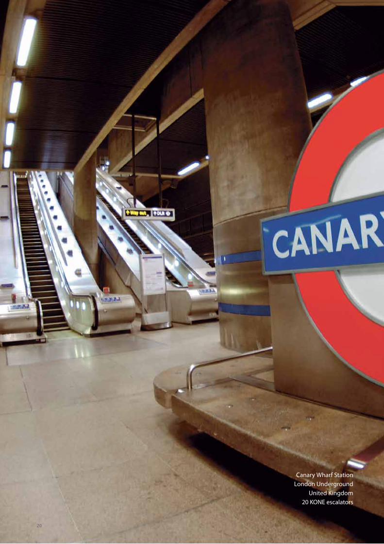
Canary Wharf StationLondon Underground
United Kingdom20 KONE escalators
20
© KONE Planning Guide for Escalators & Autowalks 21
14
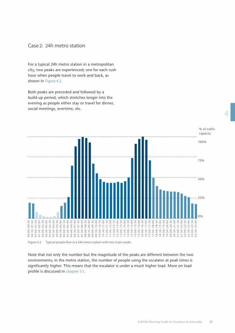
Case 2: 24h metro station
For a typical 24h metro station in a metropolitan city, two peaks are experienced; one for each rush hour when people travel to work and back, as shown in Figure 4.2.
Both peaks are preceded and followed by a build-up period, which stretches longer into the evening as people either stay or travel for dinner, social meetings, overtime, etc.
Figure 4.2 Typical people flow in a 24h metro station with two major peaks
Note that not only the number but the magnitude of the peaks are different between the two environments; in the metro station, the number of people using the escalator at peak times is significantly higher. This means that the escalator is under a much higher load. More on load profile is discussed in chapter 5.1.
00
:00
–0
0:3
0
00
:30
–0
1:0
0
01
:00
–0
1:3
0
01
:30
–0
2:0
0
02
:00
–0
2:3
0
02
:30
–0
3:0
0
03
:00
–0
3:3
0
03
:30
–0
4:0
0
04
:00
–0
4:3
0
04
:30
–0
5:0
0
05
:00
–0
5:3
0
05
:50
–0
6:0
0
06
:00
–0
6:3
0
06
:30
–0
7:0
0
07
:00
–0
7:3
0
07
:30
–0
8:0
0
08
:00
–0
8:3
0
08
:30
–0
9:0
0
09
:00
–0
9:3
0
09
:30
–1
0:0
0
10
:00
–1
0:3
0
10
:30
–1
1:0
0
11
:00
–1
1:3
0
11
:30
–1
2:0
0
12
:00
-12
:30
12
:30
–1
3:0
0
13
:00
–1
3:3
0
13
:30
–1
4:0
0
14
:00
–1
4:3
0
14
:30
–1
5:0
0
15
:00
–1
5:3
0
15
:30
–1
6:0
0
16
:00
–1
6:3
0
16
:30
–1
7:0
0
17
:00
–1
7:3
0
17
:30
–1
8:0
0
18
:00
–1
8:3
0
18
:30
–1
9:0
0
19
:00
–1
9:3
0
19
:30
–2
0:0
0
20
:00
–2
0:3
0
20
:30
–2
1:0
0
21
:00
–2
1:3
0
21
:30
–2
2:0
0
22
:00
–2
2:3
0
22
:30
–2
3:0
0
23
:00
–2
3:3
0
23
:30
–2
4:0
0
100%
75%
50%
25%
0%
% of traffic capacity
22 © KONE Planning Guide for Escalators & Autowalks
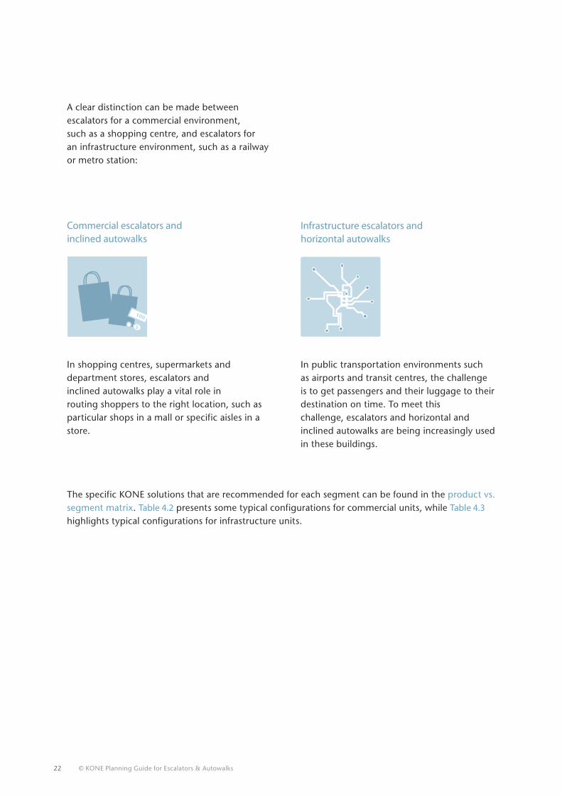
A clear distinction can be made between escalators for a commercial environment, such as a shopping centre, and escalators for an infrastructure environment, such as a railway or metro station:
Infrastructure escalators and horizontal autowalks
Commercial escalators and inclined autowalks
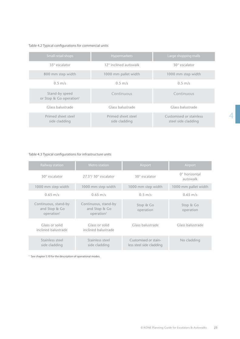
The specific KONE solutions that are recommended for each segment can be found in the product vs. segment matrix. Table 4.2 presents some typical configurations for commercial units, while Table 4.3 highlights typical configurations for infrastructure units.
5
100
In shopping centres, supermarkets and department stores, escalators and inclined autowalks play a vital role in routing shoppers to the right location, such as particular shops in a mall or specific aisles in a store.
In public transportation environments such as airports and transit centres, the challenge is to get passengers and their luggage to their destination on time. To meet thischallenge, escalators and horizontal and inclined autowalks are being increasingly used in these buildings.
© KONE Planning Guide for Escalators & Autowalks 23
14
Railway station Metro station Airport Airport
30° escalator 27.3°/ 30° escalator 30° escalator0° horizontal
autowalk
1000 mm step width 1000 mm step width 1000 mm step width 1000 mm pallet width
0.65 m/s 0.65 m/s 0.5 m/s 0.65 m/s
Continuous, stand-by and Stop & Go
operation1
Continuous, stand-by and Stop & Go
operation1
Stop & Go operation
Stop & Go operation
Glass or solid inclined balustrade
Glass or solid inclined balustrade
Glass balustrade Glass balustrade
Stainless steel side cladding
Stainless steel side cladding
Customised or stain-less steel side cladding
No cladding
Table 4.3 Typical configurations for infrastructure units
Table 4.2 Typical configurations for commercial units
1 See chapter 5.10 for the description of operational modes.
Small retail shops Hypermarkets Large shopping malls
35° escalator 12° inclined autowalk 30° escalator
800 mm step width 1000 mm pallet width 1000 mm step width
0.5 m/s 0.5 m/s 0.5 m/s
Stand-by speed or Stop & Go operation1
Continuous Continuous
Glass balustrade Glass balustrade Glass balustrade
Primed sheet steel side cladding
Primed sheet steel side cladding
Customised or stainless steel side cladding
24 © KONE Planning Guide for Escalators & Autowalks
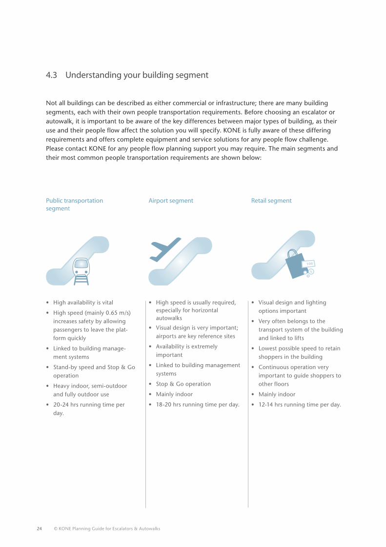
4.3 Understanding your building segment
Not all buildings can be described as either commercial or infrastructure; there are many building segments, each with their own people transportation requirements. Before choosing an escalator or autowalk, it is important to be aware of the key differences between major types of building, as their use and their people flow affect the solution you will specify. KONE is fully aware of these differing requirements and offers complete equipment and service solutions for any people flow challenge. Please contact KONE for any people flow planning support you may require. The main segments and their most common people transportation requirements are shown below:
Public transportation segment
Airport segment Retail segment
5
100
• High availability is vital
• High speed (mainly 0.65 m/s) increases safety by allowing passengers to leave the plat-form quickly
• Linked to building manage-ment systems
• Stand-by speed and Stop & Go operation
• Heavy indoor, semi-outdoor and fully outdoor use
• 20-24 hrs running time per day.
• High speed is usually required, especially for horizontal autowalks
• Visual design is very important; airports are key reference sites
• Availability is extremely important
• Linked to building management systems
• Stop & Go operation
• Mainly indoor
• 18-20 hrs running time per day.
• Visual design and lighting options important
• Very often belongs to the transport system of the building and linked to lifts
• Lowest possible speed to retain shoppers in the building
• Continuous operation very important to guide shoppers to other floors
• Mainly indoor
• 12-14 hrs running time per day.
© KONE Planning Guide for Escalators & Autowalks 25
14
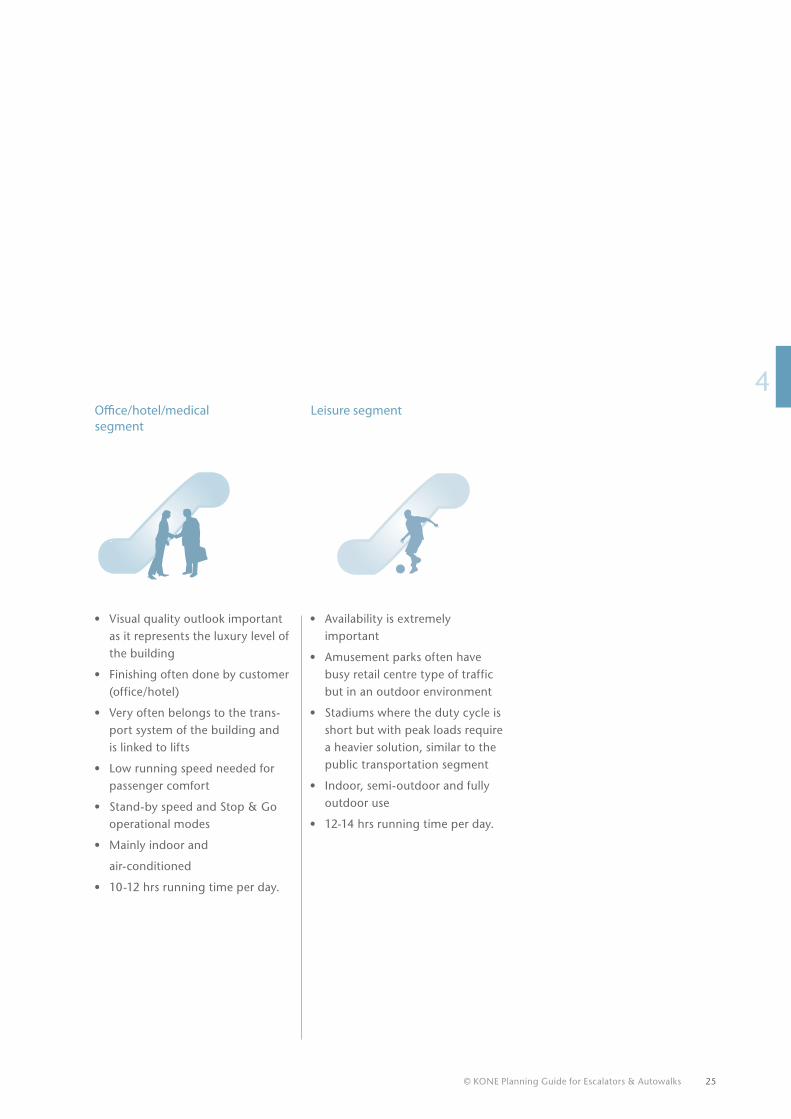
Office/hotel/medicalsegment
Leisure segment
• Visual quality outlook important as it represents the luxury level of the building
• Finishing often done by customer (office/hotel)
• Very often belongs to the trans-port system of the building and is linked to lifts
• Low running speed needed for passenger comfort
• Stand-by speed and Stop & Go operational modes
• Mainly indoor and
air-conditioned
• 10-12 hrs running time per day.
• Availability is extremely important
• Amusement parks often have busy retail centre type of traffic but in an outdoor environment
• Stadiums where the duty cycle is short but with peak loads require a heavier solution, similar to the public transportation segment
• Indoor, semi-outdoor and fully outdoor use
• 12-14 hrs running time per day.
4.4 Deciding how many escalators and/or autowalks are needed
The number of units required is determined by the people flow requirements (the number of people transported per hour). This depends on parameters such as:
• The type of building
• The traffic flow within the building
• Peak traffic times
• The level of travel comfort required.
In addition, factors such as safety, evacuation, accessibility and even the marketing potential (of a retail centre) come into play. The next consideration is where to locate your escalators and autowalks.
26 © KONE Planning Guide for Escalators & Autowalks
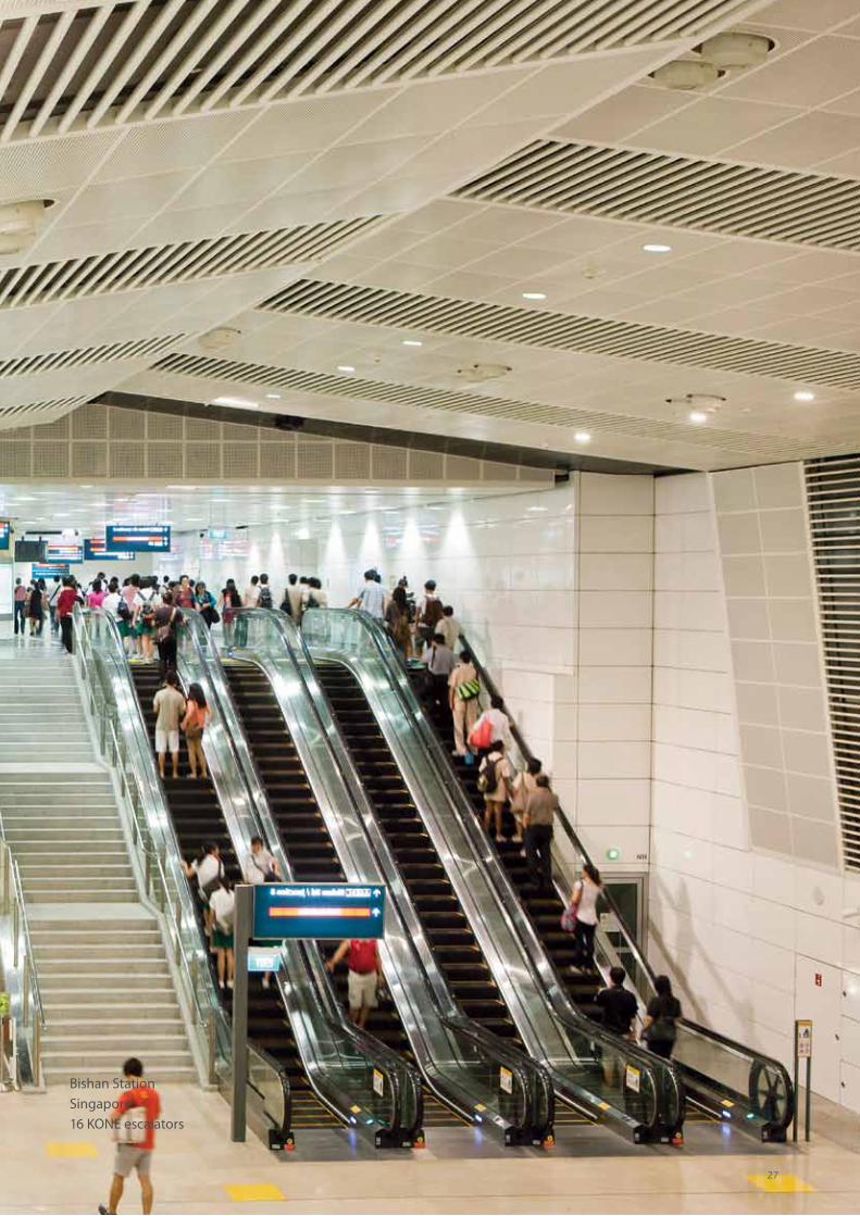
Bishan StationSingapore16 KONE escalators
27
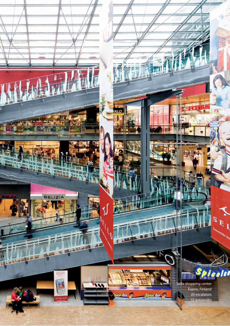
Sello shopping centerEspoo, Finland
20 escalators12 autowalks
28
14
To ensure the reliability and availability of your escalators and autowalks over their lifetime, it is essential that their specifications match the environmental conditions.
Most escalators and autowalks will normally be installed indoors. They are designed for such an environment as standard. An indoor environment is defined as a weather-tight, temperature controlled environment where the escalator or autowalk will not be exposed to the elements such as rain and snow.
An outdoor environment can be either semi-outdoor or fully outdoor
Semi-outdoor is an uncontrolled environment in
which the unit might be exposed at times to the
elements. However, as it is covered with a roof and
walls, the escalator is not directly exposed to the
elements.
Fully outdoor is an uncontrolled environment where
the unit will be fully exposed to the elements. A key
consideration is therefore the temperature; heaters
and/or coolers may have to be installed, depending
on the climate.
4.5 Locating your escalators and autowalks – indoors or outdoors?
29
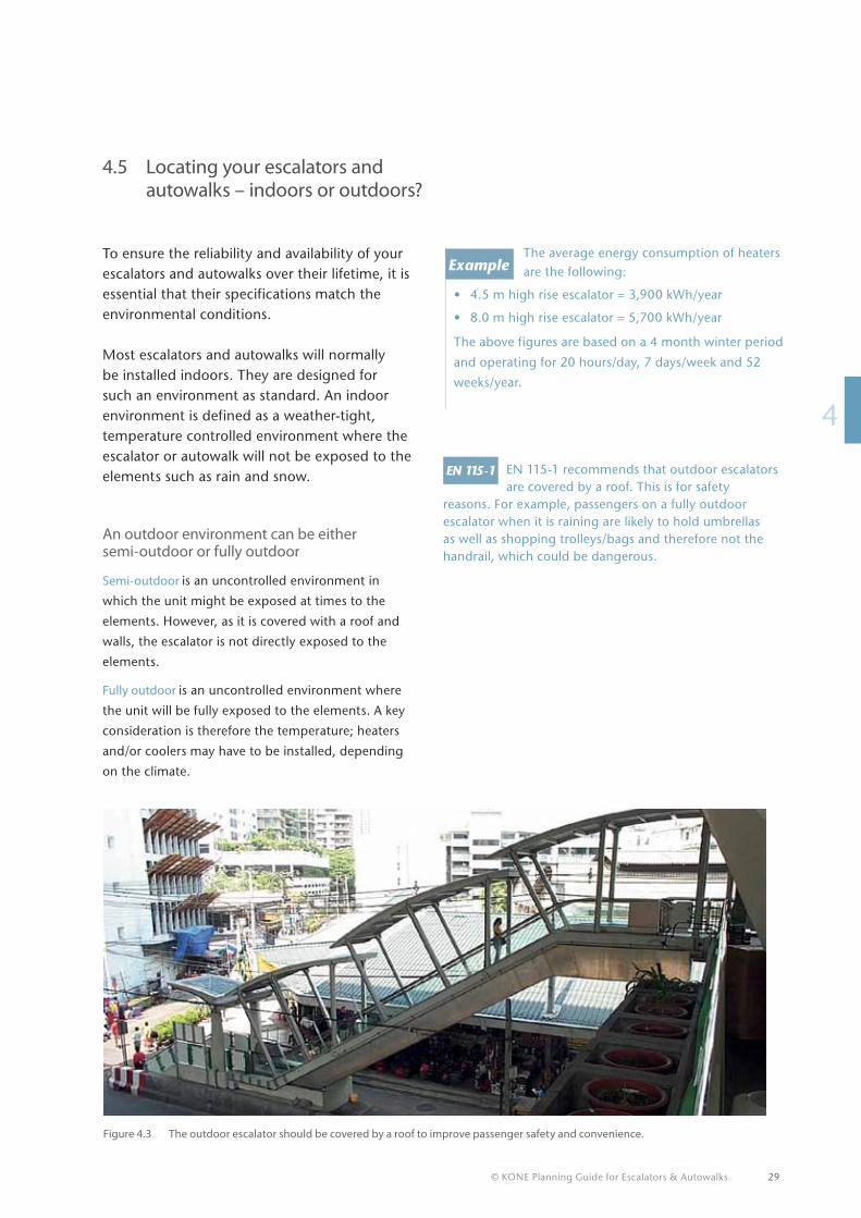
EN 115-1 recommends that outdoor escalators are covered by a roof. This is for safety
reasons. For example, passengers on a fully outdoor escalator when it is raining are likely to hold umbrellas as well as shopping trolleys/bags and therefore not the handrail, which could be dangerous.
The average energy consumption of heaters are the following:
• 4.5 m high rise escalator = 3,900 kWh/year
• 8.0 m high rise escalator = 5,700 kWh/year
The above figures are based on a 4 month winter period
and operating for 20 hours/day, 7 days/week and 52
weeks/year.
Figure 4.3 The outdoor escalator should be covered by a roof to improve passenger safety and convenience.
?
© KONE Planning Guide for Escalators & Autowalks
6.
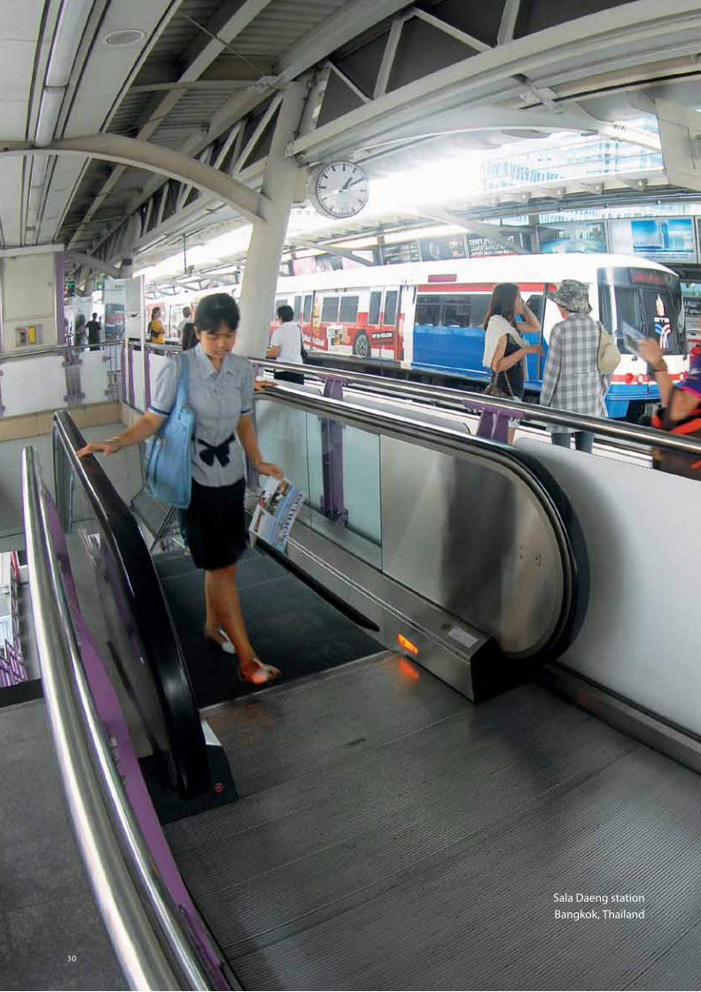
Sala Daeng stationBangkok, Thailand
30
© KONE Planning Guide for Escalators & Autowalks 31
14
14
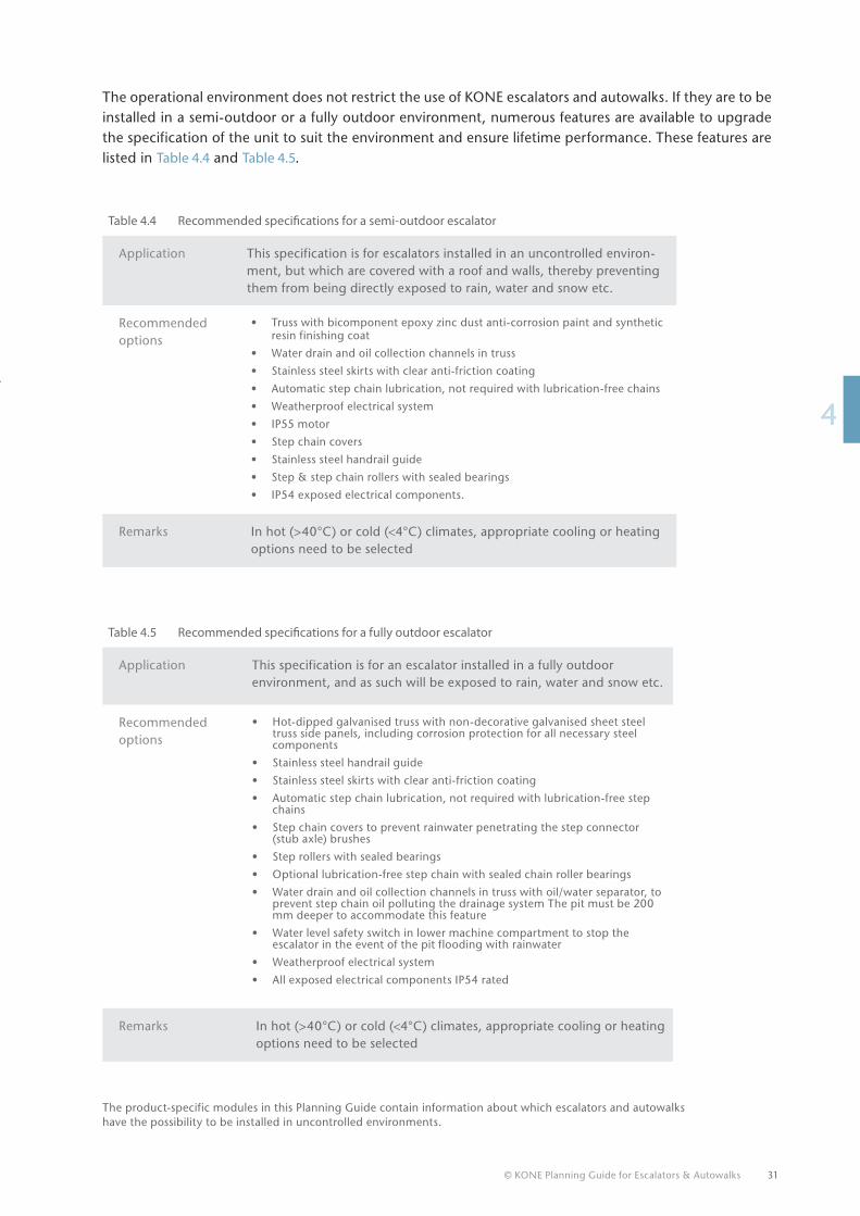
Table 4.4 Recommended specifications for a semi-outdoor escalator
Application This specification is for escalators installed in an uncontrolled environ-ment, but which are covered with a roof and walls, thereby preventing them from being directly exposed to rain, water and snow etc.
Recommended options
• Truss with bicomponent epoxy zinc dust anti-corrosion paint and synthetic resin finishing coat
• Water drain and oil collection channels in truss
• Stainless steel skirts with clear anti-friction coating
• Automatic step chain lubrication, not required with lubrication-free chains
• Weatherproof electrical system
• IP55 motor
• Step chain covers
• Stainless steel handrail guide
• Step & step chain rollers with sealed bearings
• IP54 exposed electrical components.
Remarks In hot (>40°C) or cold (<4°C) climates, appropriate cooling or heating options need to be selected
Table 4.5 Recommended specifications for a fully outdoor escalator
Application This specification is for an escalator installed in a fully outdoor environment, and as such will be exposed to rain, water and snow etc.
Recommended options
• Hot-dipped galvanised truss with non-decorative galvanised sheet steel truss side panels, including corrosion protection for all necessary steel components
• Stainless steel handrail guide
• Stainless steel skirts with clear anti-friction coating
• Automatic step chain lubrication, not required with lubrication-free step chains
• Step chain covers to prevent rainwater penetrating the step connector (stub axle) brushes
• Step rollers with sealed bearings
• Optional lubrication-free step chain with sealed chain roller bearings
• Water drain and oil collection channels in truss with oil/water separator, to prevent step chain oil polluting the drainage system The pit must be 200 mm deeper to accommodate this feature
• Water level safety switch in lower machine compartment to stop the escalator in the event of the pit flooding with rainwater
• Weatherproof electrical system
• All exposed electrical components IP54 rated
Remarks In hot (>40°C) or cold (<4°C) climates, appropriate cooling or heating options need to be selected
The operational environment does not restrict the use of KONE escalators and autowalks. If they are to be installed in a semi-outdoor or a fully outdoor environment, numerous features are available to upgrade the specification of the unit to suit the environment and ensure lifetime performance. These features are listed in Table 4.4 and Table 4.5.
The product-specific modules in this Planning Guide contain information about which escalators and autowalks have the possibility to be installed in uncontrolled environments.
6.
32 © KONE Planning Guide for Escalators & Autowalks
4.6 Arranging your escalators or inclined autowalks in the building
Escalators are generally acknowledged as being the most effective method of transporting large numbers of people between two floor levels, but how your escalators are arranged within the building has a huge impact on the flow of people. More specific information on this topic and how it relates to construction considerations is provided in chapter 5.
In infrastructure buildings
• Escalators are normally positioned on the main routes through the building
• The over-riding requirement is speed and efficiency of people transportation within a safe environment.
In retail stores
• Positioning an escalator next to the main entrance is the most effective way to encourage customers to use a sales area on another floor level
• In a retail environment the goal is not merely to convey passengers to another floor as quickly as possible. An escalator can lead people through a promotional area or alongside displays of goods.
Note that the actual arrangement of the escalator installation can have a dramatic impact on the interior design of the building. The most common escalator arrangements are shown on the following pages, along with advantages and disadvantages of each configuration. KONE escalators are designed to be operated in both directions, so at this stage you do not necessarily have to stipulate the direction of travel.
© KONE Planning Guide for Escalators & Autowalks
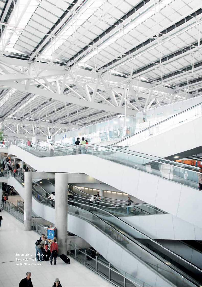
Suvarnabhumi Airport Bangkok, Thailand24 KONE autowalks
33
34 © KONE Planning Guide for Escalators & Autowalks
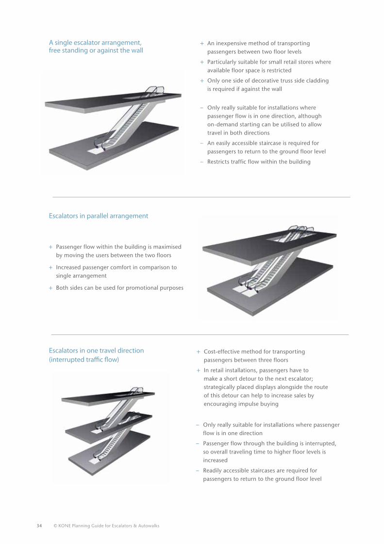
+ Passenger flow within the building is maximised by moving the users between the two floors
+ Increased passenger comfort in comparison to single arrangement
+ Both sides can be used for promotional purposes
+ An inexpensive method of transporting passengers between two floor levels
+ Particularly suitable for small retail stores where available floor space is restricted
+ Only one side of decorative truss side cladding is required if against the wall
– Only really suitable for installations where passenger flow is in one direction, although on-demand starting can be utilised to allow travel in both directions
– An easily accessible staircase is required for passengers to return to the ground floor level
– Restricts traffic flow within the building
+ Cost-effective method for transporting passengers between three floors
+ In retail installations, passengers have to make a short detour to the next escalator; strategically placed displays alongside the route of this detour can help to increase sales by encouraging impulse buying
– Only really suitable for installations where passenger flow is in one direction
– Passenger flow through the building is interrupted, so overall traveling time to higher floor levels is increased
– Readily accessible staircases are required for passengers to return to the ground floor level
Escalators in one travel direction (interrupted traffic flow)
A single escalator arrangement, free standing or against the wall
Escalators in parallel arrangement
© KONE Planning Guide for Escalators & Autowalks 35
14
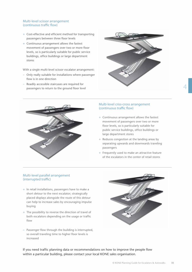
Multi-level scissor arrangement (continuous traffic flow)
+ Cost-effective and efficient method for transporting passengers between three floor levels
+ Continuous arrangement allows the fastest movement of passengers over two or more floor levels, so is particularly suitable for public service buildings, office buildings or large department stores
With a single multi-level scissor escalator arrangement:
– Only really suitable for installations where passenger flow is in one direction
– Readily accessible staircases are required for passengers to return to the ground floor level
Multi-level parallel arrangement (interrupted traffic)
+ In retail installations, passengers have to make a short detour to the next escalator; strategically placed displays alongside the route of this detour can help to increase sales by encouraging impulse buying
+ The possibility to reverse the direction of travel of both escalators depending on the usage or traffic flow
– Passenger flow through the building is interrupted, so overall traveling time to higher floor levels is increased
If you need traffic planning data or recommendations on how to improve the people flow within a particular building, please contact your local KONE sales organisation.
Multi-level criss-cross arrangement (continuous traffic flow)
+ Continuous arrangement allows the fastest movement of passengers over two or more floor levels, so is particularly suitable for public service buildings, office buildings or large department stores
+ Reduces congestion at the landing areas by separating upwards and downwards traveling passengers
+ Frequently used to make an attractive feature of the escalators in the center of retail stores
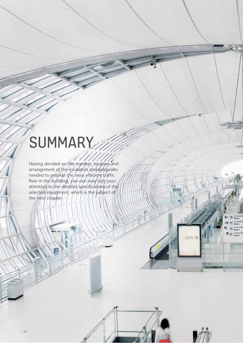
sUmmARyHaving decided on the number, location and arrangement of the escalators and autowalks needed to provide the most efficient traffic flow in the building, you can now turn your attention to the detailed specifications of the selected equipment, which is the subject of the next chapter.
36
© KONE Planning Guide for Escalators & Autowalks 37
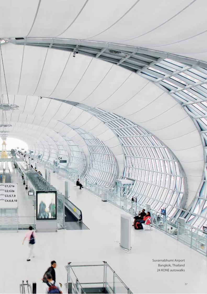
Suvarnabhumi Airport Bangkok, Thailand
24 KONE autowalks
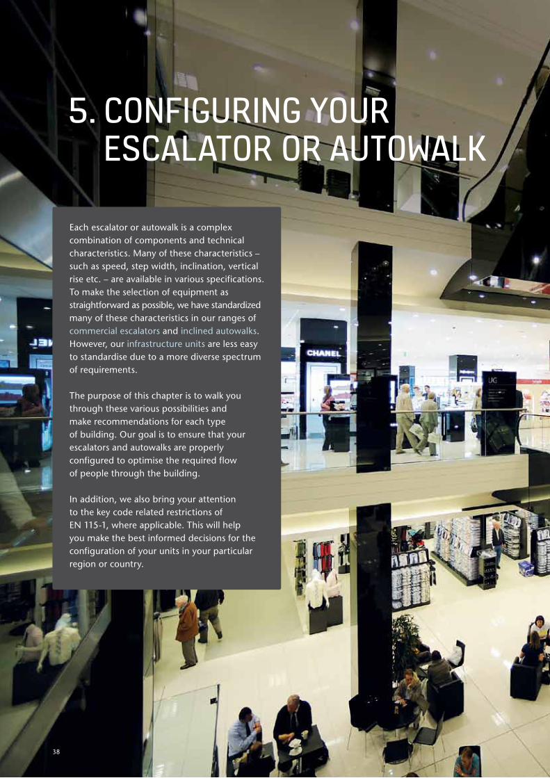
Each escalator or autowalk is a complex combination of components and technical characteristics. Many of these characteristics – such as speed, step width, inclination, vertical rise etc. – are available in various specifications. To make the selection of equipment as straightforward as possible, we have standardized many of these characteristics in our ranges of commercial escalators and inclined autowalks. However, our infrastructure units are less easy to standardise due to a more diverse spectrum of requirements.
The purpose of this chapter is to walk you through these various possibilities and make recommendations for each type of building. Our goal is to ensure that your escalators and autowalks are properly configured to optimise the required flow of people through the building.
In addition, we also bring your attention to the key code related restrictions of EN 115-1, where applicable. This will help you make the best informed decisions for the configuration of your units in your particular region or country.
5. cONFIGURING yOUR EscALATOR OR AUTOWALK
38
39
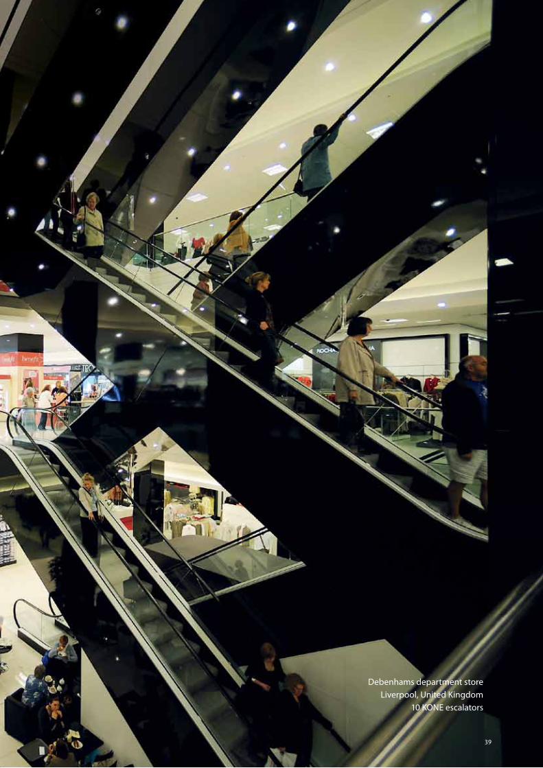
Debenhams department storeLiverpool, United Kingdom
10 KONE escalators
40 © KONE Planning Guide for Escalators & Autowalks
5.1 Load profile
In chapter 4.2 (metro station) we briefly mentioned the load profile. This is the indication of the passenger flow in a building and how the escalators and autowalks are stressed. A load profile is based on the quantity of passengers traveling on an escalator or autowalk, and the length of time and frequency they spend riding it. As we have seen, a load profile for a commercial escalator in a retail center is going to be different from that of an infrastructure escalator in a city metro station.
Maximum step load
This is the maximum load on a particular step at any time. It is based on average weights of passengers and takes into consideration:
• Not every step is occupied all the time
• Only the visible steps can be loaded
• The step width, which influences the number of passengers.
Average level of use
The level of use of an escalator varies throughout the day. In most public transportation settings, peaks occur during rush hours, but for most of the day there is less traffic. Each load profile has an average percentage based on the height and frequency of these peaks, troughs and plateaus.
Minimum safety factor
Different key components have different set tolerances, which exceed the load by a set factor. In other words, they are stronger or more durable. This is indicated by the safety factor (SF).
Truss
When the length of the escalator/inclined autowalk results in the truss exceeding the maximum permitted deflection between the supports required by the local safety codes and specification requirements etc., you should provide an intermediate truss support (see chapter 7.3). Please contact your local sales organisation for more details.
The following factors have an influence on the load profile:
© KONE Planning Guide for Escalators & Autowalks 41
15
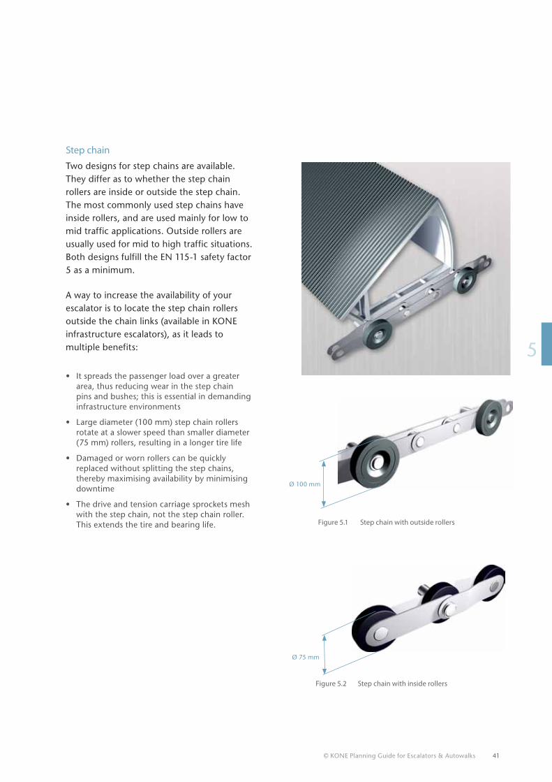
Step chain
Two designs for step chains are available. They differ as to whether the step chain rollers are inside or outside the step chain. The most commonly used step chains have inside rollers, and are used mainly for low to mid traffic applications. Outside rollers are usually used for mid to high traffic situations. Both designs fulfill the EN 115-1 safety factor 5 as a minimum.
A way to increase the availability of your escalator is to locate the step chain rollers outside the chain links (available in KONE infrastructure escalators), as it leads to multiple benefits:
• It spreads the passenger load over a greater area, thus reducing wear in the step chain pins and bushes; this is essential in demanding infrastructure environments
• Large diameter (100 mm) step chain rollers rotate at a slower speed than smaller diameter (75 mm) rollers, resulting in a longer tire life
• Damaged or worn rollers can be quickly replaced without splitting the step chains, thereby maximising availability by minimising downtime
• The drive and tension carriage sprockets mesh with the step chain, not the step chain roller. This extends the tire and bearing life.
Ø 75 mm
Ø 100 mm
Figure 5.2 Step chain with inside rollers
Figure 5.1 Step chain with outside rollers
At KONE we take very seriously our commitment to eco-efficiency, which we define as the concept of creating better goods and services while using fewer resources and creating less waste and pollution. Eco-efficiency is therefore an integral part of KONE’s processes and our objective is to lead the industry in eco-efficiency. Today we supply excellent Eco-efficient™ products and services, and constantly work at minimising the carbon footprint of our own operations.
42
© KONE Planning Guide for Escalators & Autowalks 43
15
5.2 Energy consumption
KONE has developed measures and innovations to cut the energy consumption of escalators and autowalks. Our starting point is obtaining precise information on areas such as:
• Motor power, which is defined by the cut-off rises (the motor power needed per rise limitation) of an escalator platform
• Passenger usage (frequent or low use, leading to load profile calculations)
• Mechanical, electrical and structural energy-saving features
• Energy consumption of optional equipment (lighting, heating, cooling)
• Quality aspects (proper maintenance, adjustments for reduced friction).
In addition, our global manufacturing network has adopted ISO 14001, the most well-known and globally recognised environmental management system standard. Most of our manufacturing facilities and country organisations hold ISO 14001 certification, and KONE Corporation complied with ISO 14001 in early 2009.
To enhance the eco-efficiency of your operations, consider the options listed on the following pages. Many of the solutions described in this chapter are also available as easy to install retrofit packages.
KONE has developed an advanced energy consumption tool, that can be utilised to calculate the total energy consumption of the escalator or autowalk. This tool can be used to verify the impact of different operational parameters and product options to the total energy consumption. Please feel free to contact the local KONE sales organisation for specific energy consumption figures and detailed analysis and recommendations.
KONE Direct DriveThe KONE-designed Direct Drive helps cut both operating costs and your building’s carbon footprint. By replacing the conventional worm gear with the KONE Direct Drive, mechanical losses have been minimised, reducing the drive’s energy consumption by up to 20%.
44 © KONE Planning Guide for Escalators & Autowalks
4
5
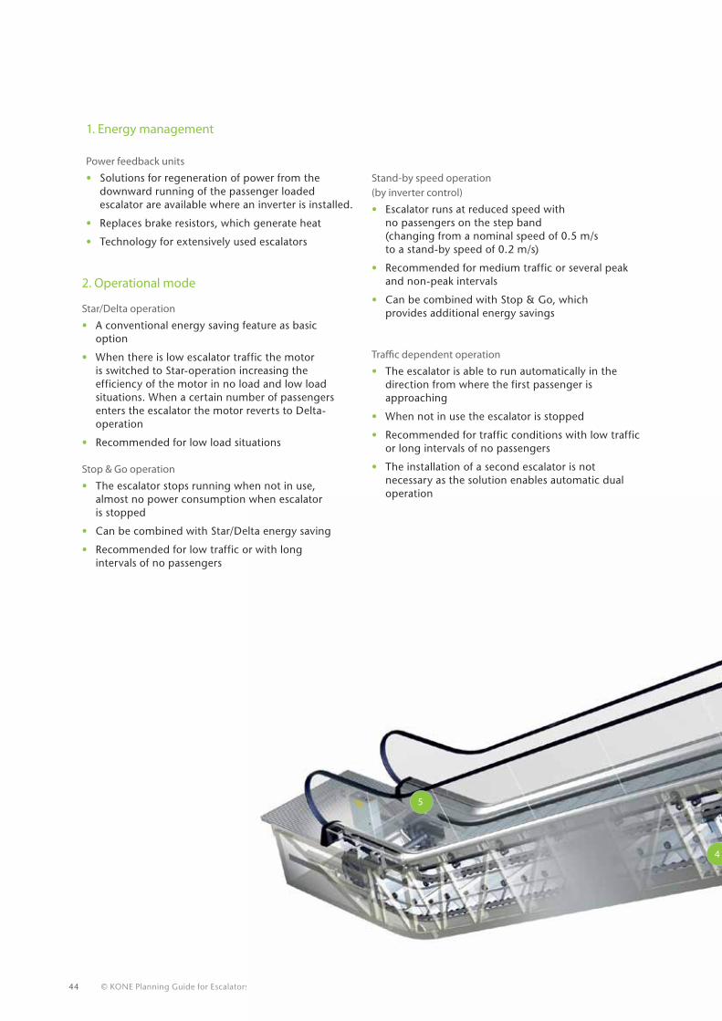
1. Energy management Power feedback units
• Solutions for regeneration of power from the downward running of the passenger loaded escalator are available where an inverter is installed.
• Replaces brake resistors, which generate heat
• Technology for extensively used escalators
2. Operational mode
Star/Delta operation
• A conventional energy saving feature as basic option
• When there is low escalator traffic the motor is switched to Star-operation increasing the efficiency of the motor in no load and low load situations. When a certain number of passengers enters the escalator the motor reverts to Delta-operation
• Recommended for low load situations
Stop & Go operation
• The escalator stops running when not in use, almost no power consumption when escalator is stopped
• Can be combined with Star/Delta energy saving
• Recommended for low traffic or with long intervals of no passengers
Stand-by speed operation(by inverter control)
• Escalator runs at reduced speed with no passengers on the step band (changing from a nominal speed of 0.5 m/s to a stand-by speed of 0.2 m/s)
• Recommended for medium traffic or several peak and non-peak intervals
• Can be combined with Stop & Go, which provides additional energy savings
Traffic dependent operation
• The escalator is able to run automatically in the direction from where the first passenger is approaching
• When not in use the escalator is stopped
• Recommended for traffic conditions with low traffic or long intervals of no passengers
• The installation of a second escalator is not necessary as the solution enables automatic dual operation
© KONE Planning Guide for Escalators & Autowalks 45
15
1
2
3
4
3. Safety
Dynamic braking
• Electrical braking of escalator instead of mechanical braking
• Extends service intervals due to minimal brake pad wear
• Increases safety by ensuring constant braking distances independent of passenger loading and travel direction
• Requires frequency converter and a special safety circuit
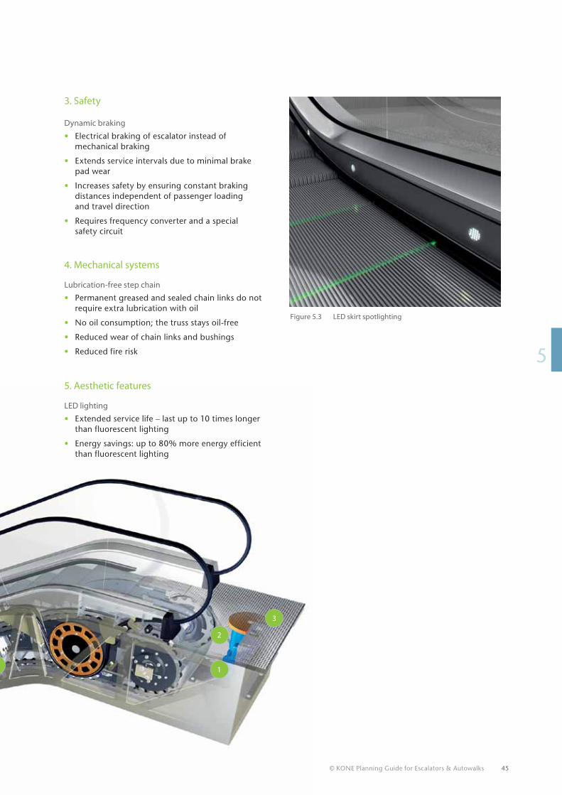
Figure 5.3 LED skirt spotlighting
4. Mechanical systems
Lubrication-free step chain
• Permanent greased and sealed chain links do not require extra lubrication with oil
• No oil consumption; the truss stays oil-free
• Reduced wear of chain links and bushings
• Reduced fire risk
5. Aesthetic features
LED lighting
• Extended service life – last up to 10 times longer than fluorescent lighting
• Energy savings: up to 80% more energy efficient than fluorescent lighting
46 © KONE Planning Guide for Escalators & Autowalks
5.3 Step width
Escalators
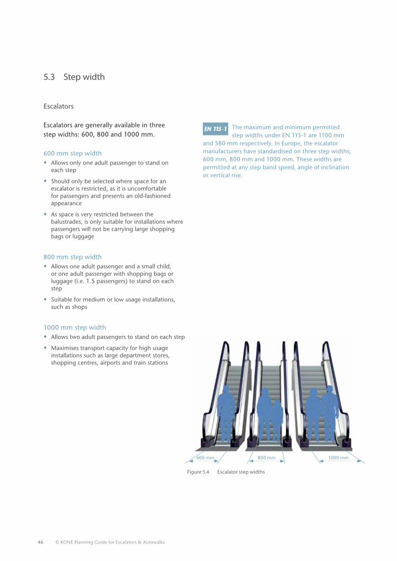
Escalators are generally available in three step widths: 600, 800 and 1000 mm.
600 mm step width • Allows only one adult passenger to stand on
each step
• Should only be selected where space for an escalator is restricted, as it is uncomfortable for passengers and presents an old-fashioned appearance
• As space is very restricted between the balustrades, is only suitable for installations where passengers will not be carrying large shopping bags or luggage
800 mm step width • Allows one adult passenger and a small child,
or one adult passenger with shopping bags or luggage (i.e. 1.5 passengers) to stand on each step
• Suitable for medium or low usage installations, such as shops
1000 mm step width • Allows two adult passengers to stand on each step
• Maximises transport capacity for high usage installations such as large department stores, shopping centres, airports and train stations
The maximum and minimum permitted step widths under EN 115-1 are 1100 mm
and 580 mm respectively. In Europe, the escalator manufacturers have standardised on three step widths; 600 mm, 800 mm and 1000 mm. These widths are permitted at any step band speed, angle of inclination or vertical rise.
600 mm 800 mm 1000 mm
Figure 5.4 Escalator step widths
© KONE Planning Guide for Escalators & Autowalks 47
1000 mm 1200 mm 1400 mm
15
The minimum and maximum permitted pallet widths under EN 115-1 for autowalks
with an angle of inclination in excess of 6° are 580 mm and 1100 mm respectively. In Europe, escalator manufacturers have standardised on three pallet widths for autowalks with an angle of inclination in excess of 6°; 800 mm, 1000 mm and 1100 mm.
The width of the shopping trolley or baggage cart and contents should be at least 400 mm less than the pallet width, to leave sufficient space for passengers to pass by.
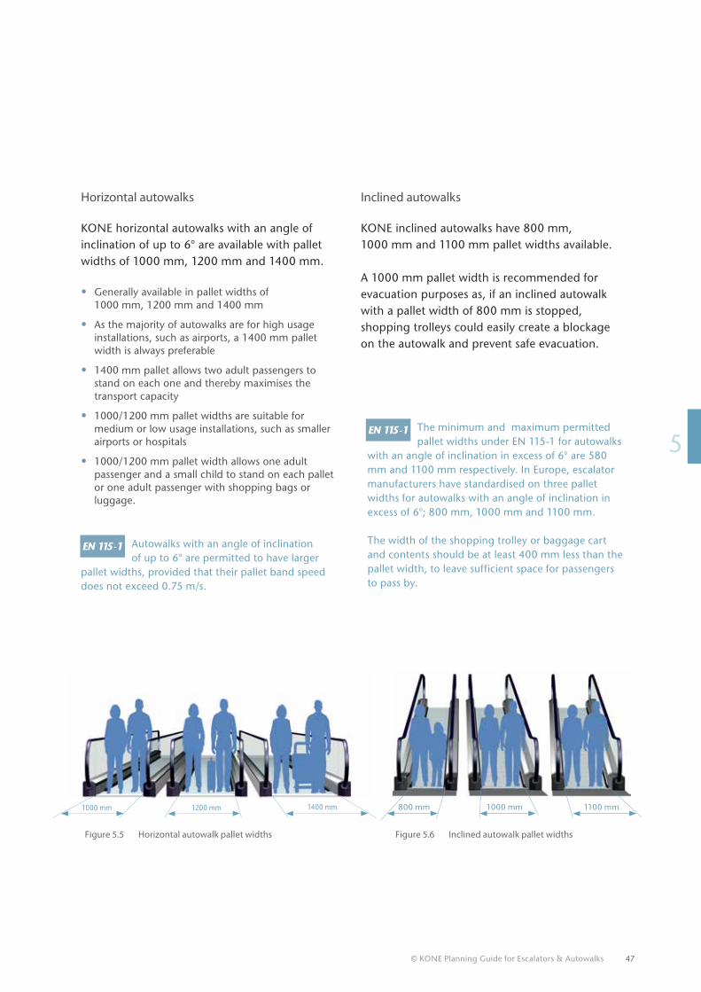
Horizontal autowalks
KONE horizontal autowalks with an angle of inclination of up to 6° are available with pallet widths of 1000 mm, 1200 mm and 1400 mm.
• Generally available in pallet widths of 1000 mm, 1200 mm and 1400 mm
• As the majority of autowalks are for high usage installations, such as airports, a 1400 mm pallet width is always preferable
• 1400 mm pallet allows two adult passengers to stand on each one and thereby maximises the transport capacity
• 1000/1200 mm pallet widths are suitable for medium or low usage installations, such as smaller airports or hospitals
• 1000/1200 mm pallet width allows one adult passenger and a small child to stand on each pallet or one adult passenger with shopping bags or luggage.
Autowalks with an angle of inclination of up to 6° are permitted to have larger
pallet widths, provided that their pallet band speed does not exceed 0.75 m/s.
Inclined autowalks
KONE inclined autowalks have 800 mm, 1000 mm and 1100 mm pallet widths available.
A 1000 mm pallet width is recommended for evacuation purposes as, if an inclined autowalk with a pallet width of 800 mm is stopped, shopping trolleys could easily create a blockage on the autowalk and prevent safe evacuation.
800 mm 1000 mm 1100 mm
Figure 5.5 Horizontal autowalk pallet widths Figure 5.6 Inclined autowalk pallet widths
48 © KONE Planning Guide for Escalators & Autowalks
5.4 Nominal speed
Escalators
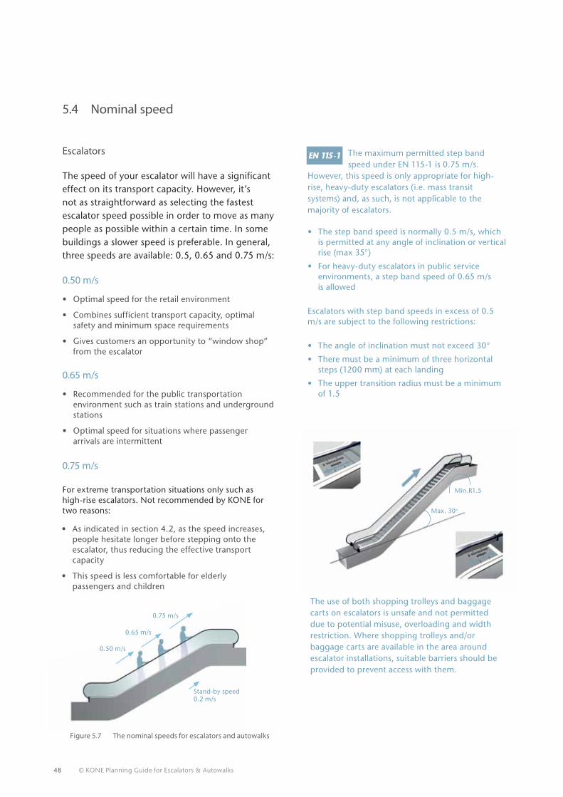
The speed of your escalator will have a significant effect on its transport capacity. However, it’s not as straightforward as selecting the fastest escalator speed possible in order to move as many people as possible within a certain time. In some buildings a slower speed is preferable. In general, three speeds are available: 0.5, 0.65 and 0.75 m/s:
0.50 m/s
• Optimal speed for the retail environment
• Combines sufficient transport capacity, optimal safety and minimum space requirements
• Gives customers an opportunity to “window shop” from the escalator
0.65 m/s
• Recommended for the public transportation environment such as train stations and underground stations
• Optimal speed for situations where passenger arrivals are intermittent
0.75 m/s
For extreme transportation situations only such as high-rise escalators. Not recommended by KONE for two reasons:
The maximum permitted step band speed under EN 115-1 is 0.75 m/s.
However, this speed is only appropriate for high-rise, heavy-duty escalators (i.e. mass transit systems) and, as such, is not applicable to the majority of escalators. • The step band speed is normally 0.5 m/s, which
is permitted at any angle of inclination or vertical rise (max 35°)
• For heavy-duty escalators in public service environments, a step band speed of 0.65 m/s is allowed
Escalators with step band speeds in excess of 0.5 m/s are subject to the following restrictions:
• The angle of inclination must not exceed 30°
• There must be a minimum of three horizontal steps (1200 mm) at each landing
• The upper transition radius must be a minimum of 1.5
The use of both shopping trolleys and baggage carts on escalators is unsafe and not permitted due to potential misuse, overloading and width restriction. Where shopping trolleys and/or baggage carts are available in the area around escalator installations, suitable barriers should be provided to prevent access with them.
Figure 5.7 The nominal speeds for escalators and autowalks
Max. 30o
Min.R1.5
• As indicated in section 4.2, as the speed increases, people hesitate longer before stepping onto the escalator, thus reducing the effective transport capacity
• This speed is less comfortable for elderly passengers and children
0.75 m/s
0.65 m/s
0.50 m/s
Stand-by speed 0.2 m/s
© KONE Planning Guide for Escalators & Autowalks 49
15
Horizontal autowalks
The three speeds available are:
• 0.5 m/s – for short autowalks or when other considerations warrant a slower speed and comfort of use
• 0.65 m/s – normally specified for autowalks as it offers a good compromise between passenger capacity, comfort and energy efficiency
• 0.75 m/s – occasionally specified for heavy-duty and/or long autowalks to increase passenger capacity and reduce travel time.
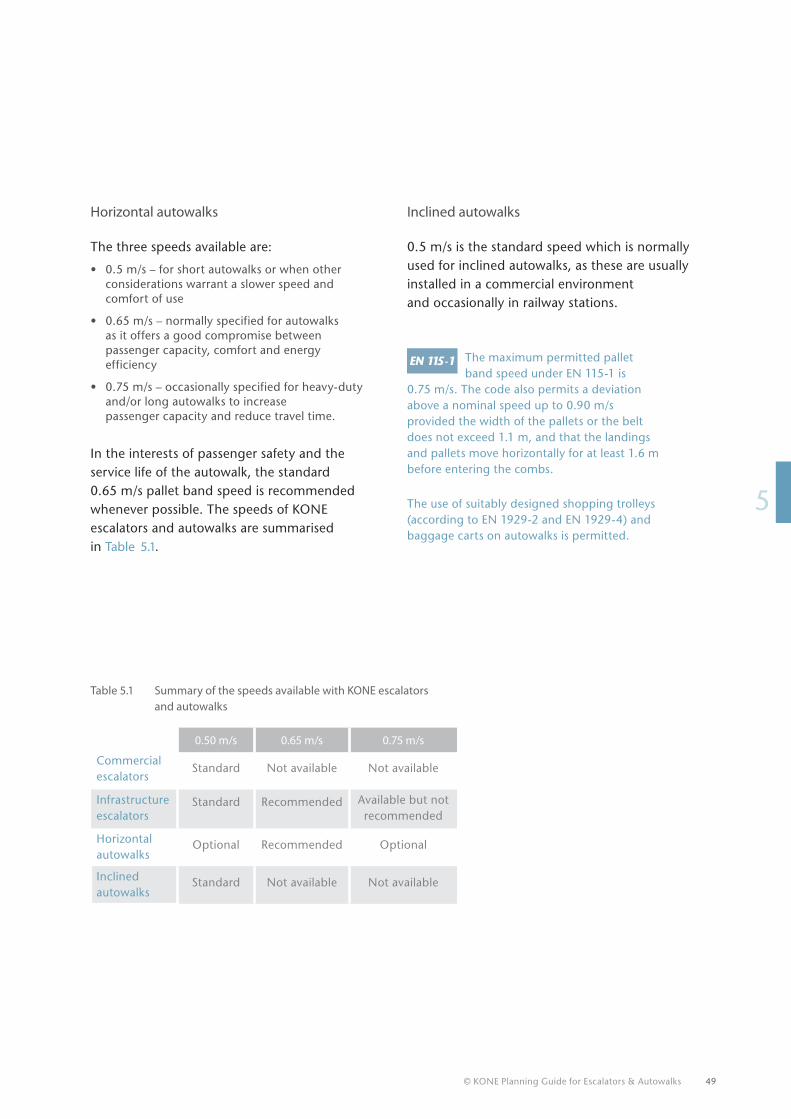
In the interests of passenger safety and the service life of the autowalk, the standard 0.65 m/s pallet band speed is recommended whenever possible. The speeds of KONE escalators and autowalks are summarised in Table 5.1.
Inclined autowalks
0.5 m/s is the standard speed which is normally used for inclined autowalks, as these are usually installed in a commercial environment and occasionally in railway stations.
The maximum permitted pallet band speed under EN 115-1 is
0.75 m/s. The code also permits a deviation above a nominal speed up to 0.90 m/s provided the width of the pallets or the belt does not exceed 1.1 m, and that the landings and pallets move horizontally for at least 1.6 m before entering the combs.
The use of suitably designed shopping trolleys (according to EN 1929-2 and EN 1929-4) and baggage carts on autowalks is permitted.
Table 5.1 Summary of the speeds available with KONE escalators and autowalks
0.50 m/s 0.65 m/s 0.75 m/s
Commercial escalators
Standard Not available Not available
Infrastructure escalators
Standard Recommended Available but not recommended
Horizontal autowalks
Optional Recommended Optional
Inclined autowalks
Standard Not available Not available
50 © KONE Planning Guide for Escalators & Autowalks
5.5 Inclination of escalators
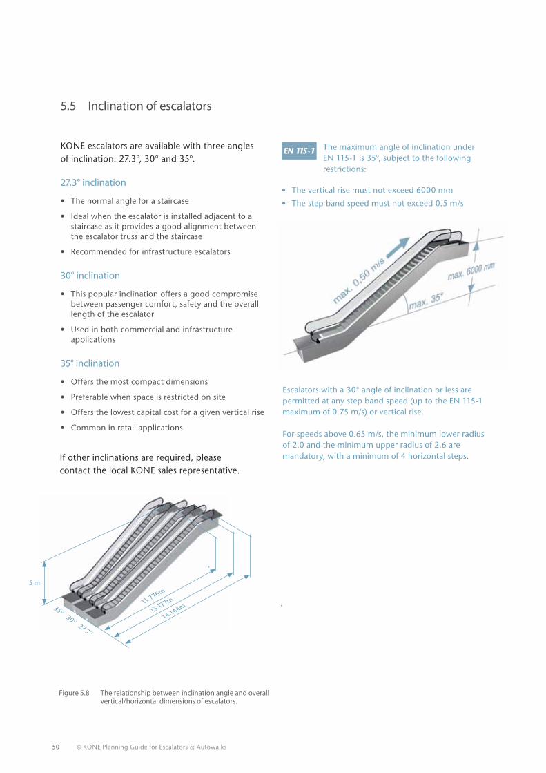
KONE escalators are available with three angles of inclination: 27.3°, 30° and 35°.
27.3° inclination
• The normal angle for a staircase
• Ideal when the escalator is installed adjacent to a staircase as it provides a good alignment between the escalator truss and the staircase
• Recommended for infrastructure escalators
30° inclination
• This popular inclination offers a good compromise between passenger comfort, safety and the overall length of the escalator
• Used in both commercial and infrastructure applications
35° inclination
• Offers the most compact dimensions
• Preferable when space is restricted on site
• Offers the lowest capital cost for a given vertical rise
• Common in retail applications
The maximum angle of inclination under EN 115-1 is 35°, subject to the following restrictions:
• The vertical rise must not exceed 6000 mm
• The step band speed must not exceed 0.5 m/s
If other inclinations are required, please contact the local KONE sales representative.
14.144m13.177m11.776m
35 O 30 O 27.3 O
Figure 5.8 The relationship between inclination angle and overall vertical/horizontal dimensions of escalators.
Escalators with a 30° angle of inclination or less are permitted at any step band speed (up to the EN 115-1 maximum of 0.75 m/s) or vertical rise.
For speeds above 0.65 m/s, the minimum lower radius of 2.0 and the minimum upper radius of 2.6 are mandatory, with a minimum of 4 horizontal steps.
5 m
© KONE Planning Guide for Escalators & Autowalks 51
15
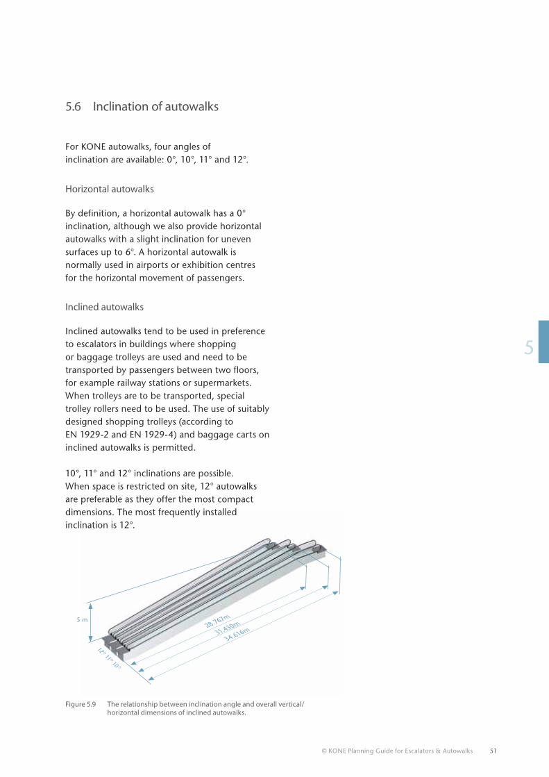
34.616m31.430m28.767m5 m
12 O 11 O 10 O
5.6 Inclination of autowalks
Figure 5.9 The relationship between inclination angle and overall vertical/horizontal dimensions of inclined autowalks.
For KONE autowalks, four angles of inclination are available: 0°, 10°, 11° and 12°.
Horizontal autowalks By definition, a horizontal autowalk has a 0° inclination, although we also provide horizontal autowalks with a slight inclination for uneven surfaces up to 6°. A horizontal autowalk is normally used in airports or exhibition centres for the horizontal movement of passengers.
Inclined autowalks
Inclined autowalks tend to be used in preference to escalators in buildings where shopping or baggage trolleys are used and need to be transported by passengers between two floors, for example railway stations or supermarkets. When trolleys are to be transported, special trolley rollers need to be used. The use of suitably designed shopping trolleys (according to EN 1929-2 and EN 1929-4) and baggage carts on inclined autowalks is permitted.
10°, 11° and 12° inclinations are possible. When space is restricted on site, 12° autowalks are preferable as they offer the most compact dimensions. The most frequently installed inclination is 12°.
52 © KONE Planning Guide for Escalators & Autowalks
5.7 Horizontal (level) steps/pallets
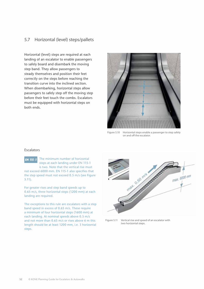
Horizontal (level) steps are required at each landing of an escalator to enable passengers to safely board and disembark the moving step band. They allow passengers to steady themselves and position their feet correctly on the steps before reaching the transition curve into the inclined section. When disembarking, horizontal steps allow passengers to safely step off the moving step before their feet touch the combs. Escalators must be equipped with horizontal steps on both ends.
Escalators
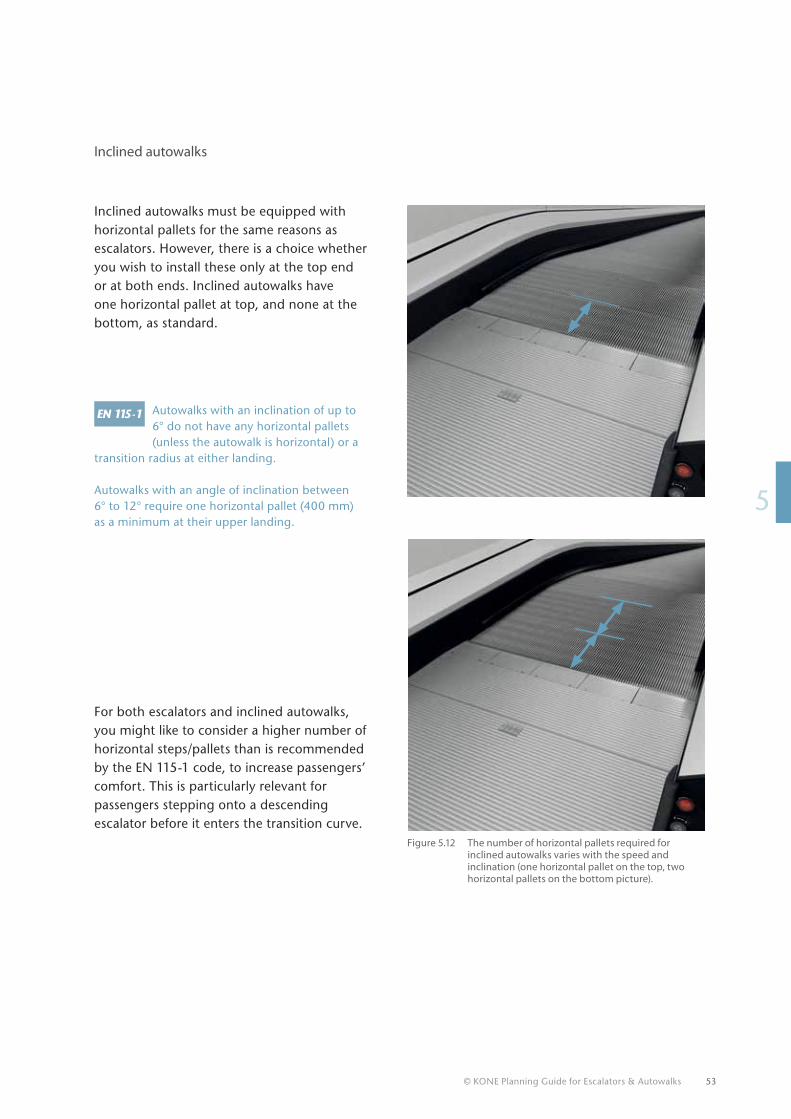
The minimum number of horizontal steps at each landing under EN 115-1 is two. Note that the vertical rise must
not exceed 6000 mm. EN 115-1 also specifies that the step speed must not exceed 0.5 m/s (see Figure 5.11).
For greater rises and step band speeds up to 0.65 m/s, three horizontal steps (1200 mm) at each landing are required.
The exceptions to this rule are escalators with a step band speed in excess of 0.65 m/s. These require a minimum of four horizontal steps (1600 mm) at each landing. At nominal speeds above 0.5 m/s and not more than 0.65 m/s or rises above 6 m this length should be at least 1200 mm, i.e. 3 horizontal steps.
Figure 5.10 Horizontal steps enable a passenger to step safely on and off the escalator.
Figure 5.11 Vertical rise and speed of an escalator with two horizontal steps.
© KONE Planning Guide for Escalators & Autowalks 53
15
For both escalators and inclined autowalks, you might like to consider a higher number of horizontal steps/pallets than is recommended by the EN 115-1 code, to increase passengers’ comfort. This is particularly relevant for passengers stepping onto a descending escalator before it enters the transition curve.
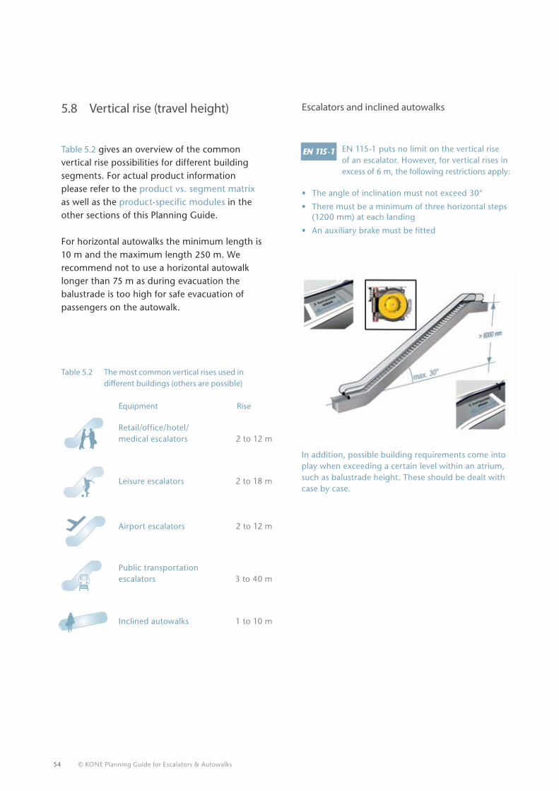
Autowalks with an inclination of up to 6° do not have any horizontal pallets (unless the autowalk is horizontal) or a
transition radius at either landing. Autowalks with an angle of inclination between 6° to 12° require one horizontal pallet (400 mm) as a minimum at their upper landing.
Inclined autowalks
Inclined autowalks must be equipped with horizontal pallets for the same reasons as escalators. However, there is a choice whether you wish to install these only at the top end or at both ends. Inclined autowalks have one horizontal pallet at top, and none at the bottom, as standard.
Figure 5.12 The number of horizontal pallets required for inclined autowalks varies with the speed and inclination (one horizontal pallet on the top, two horizontal pallets on the bottom picture).
54 © KONE Planning Guide for Escalators & Autowalks
Table 5.2 gives an overview of the common vertical rise possibilities for different building segments. For actual product information please refer to the product vs. segment matrix as well as the product-specific modules in the other sections of this Planning Guide.
For horizontal autowalks the minimum length is 10 m and the maximum length 250 m. We recommend not to use a horizontal autowalk longer than 75 m as during evacuation the balustrade is too high for safe evacuation of passengers on the autowalk.
Equipment Retail/office/hotel/medical escalators 2 to 12 m
Leisure escalators 2 to 18 m
Airport escalators 2 to 12 m
Public transportation escalators 3 to 40 m
Inclined autowalks 1 to 10 m
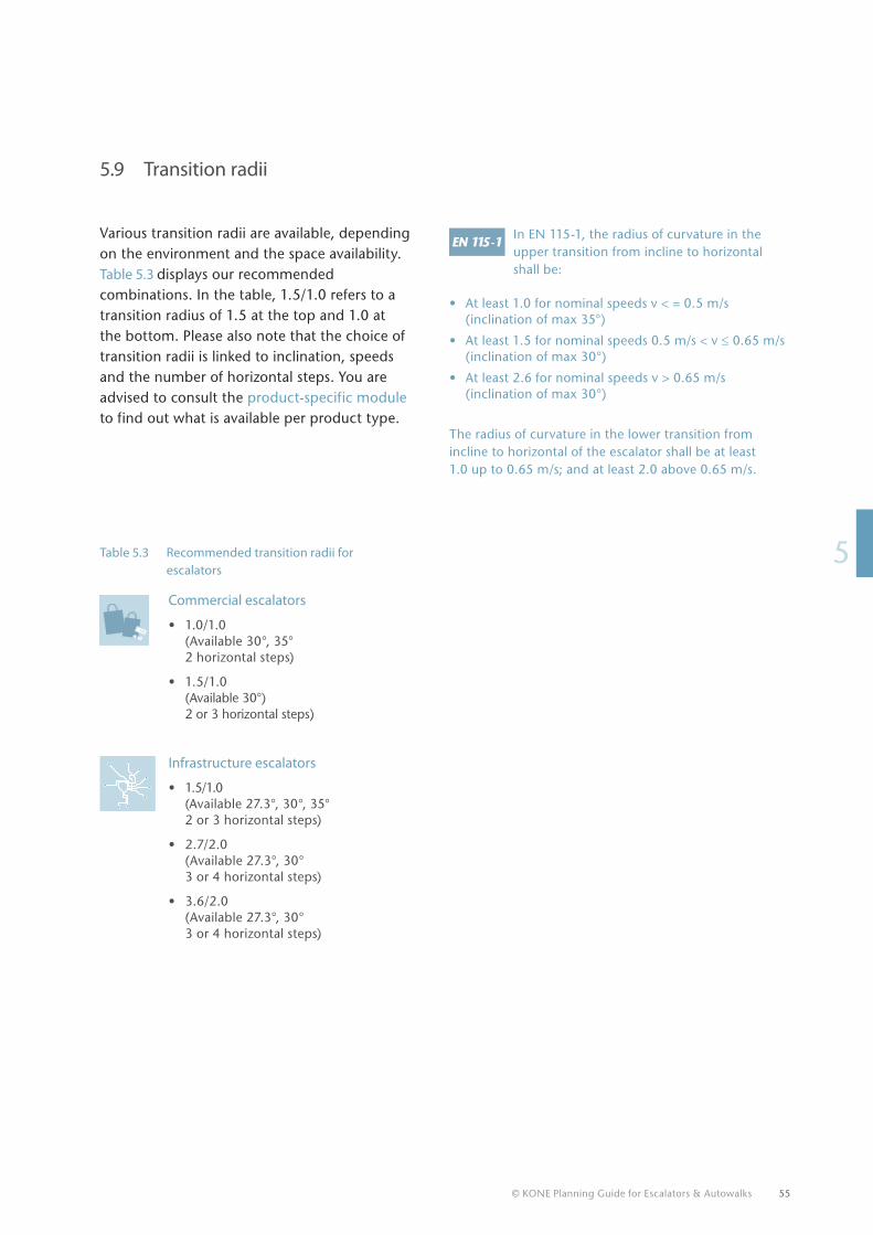
EN 115-1 puts no limit on the vertical rise of an escalator. However, for vertical rises in excess of 6 m, the following restrictions apply:
• The angle of inclination must not exceed 30°
• There must be a minimum of three horizontal steps (1200 mm) at each landing
• An auxiliary brake must be fitted
Escalators and inclined autowalks5.8 Vertical rise (travel height)
Table 5.2 The most common vertical rises used in different buildings (others are possible)
Rise
In addition, possible building requirements come into play when exceeding a certain level within an atrium, such as balustrade height. These should be dealt with case by case.
© KONE Planning Guide for Escalators & Autowalks 55
15
5.9 Transition radii
Various transition radii are available, depending on the environment and the space availability. Table 5.3 displays our recommended combinations. In the table, 1.5/1.0 refers to a transition radius of 1.5 at the top and 1.0 at the bottom. Please also note that the choice of transition radii is linked to inclination, speeds and the number of horizontal steps. You are advised to consult the product-specific module to find out what is available per product type.
Commercial escalators
• 1.0/1.0 (Available 30°, 35° 2 horizontal steps)
• 1.5/1.0 (Available 30°) 2 or 3 horizontal steps)
Infrastructure escalators
• 1.5/1.0 (Available 27.3°, 30°, 35° 2 or 3 horizontal steps)
• 2.7/2.0 (Available 27.3°, 30° 3 or 4 horizontal steps)
• 3.6/2.0 (Available 27.3°, 30° 3 or 4 horizontal steps)
In EN 115-1, the radius of curvature in the upper transition from incline to horizontal shall be:
• At least 1.0 for nominal speeds v < = 0.5 m/s (inclination of max 35°)
• At least 1.5 for nominal speeds 0.5 m/s < v ≤ 0.65 m/s (inclination of max 30°)
• At least 2.6 for nominal speeds v > 0.65 m/s (inclination of max 30°)
The radius of curvature in the lower transition from incline to horizontal of the escalator shall be at least 1.0 up to 0.65 m/s; and at least 2.0 above 0.65 m/s.
Table 5.3 Recommended transition radii for escalators
5
100
56 © KONE Planning Guide for Escalators & Autowalks
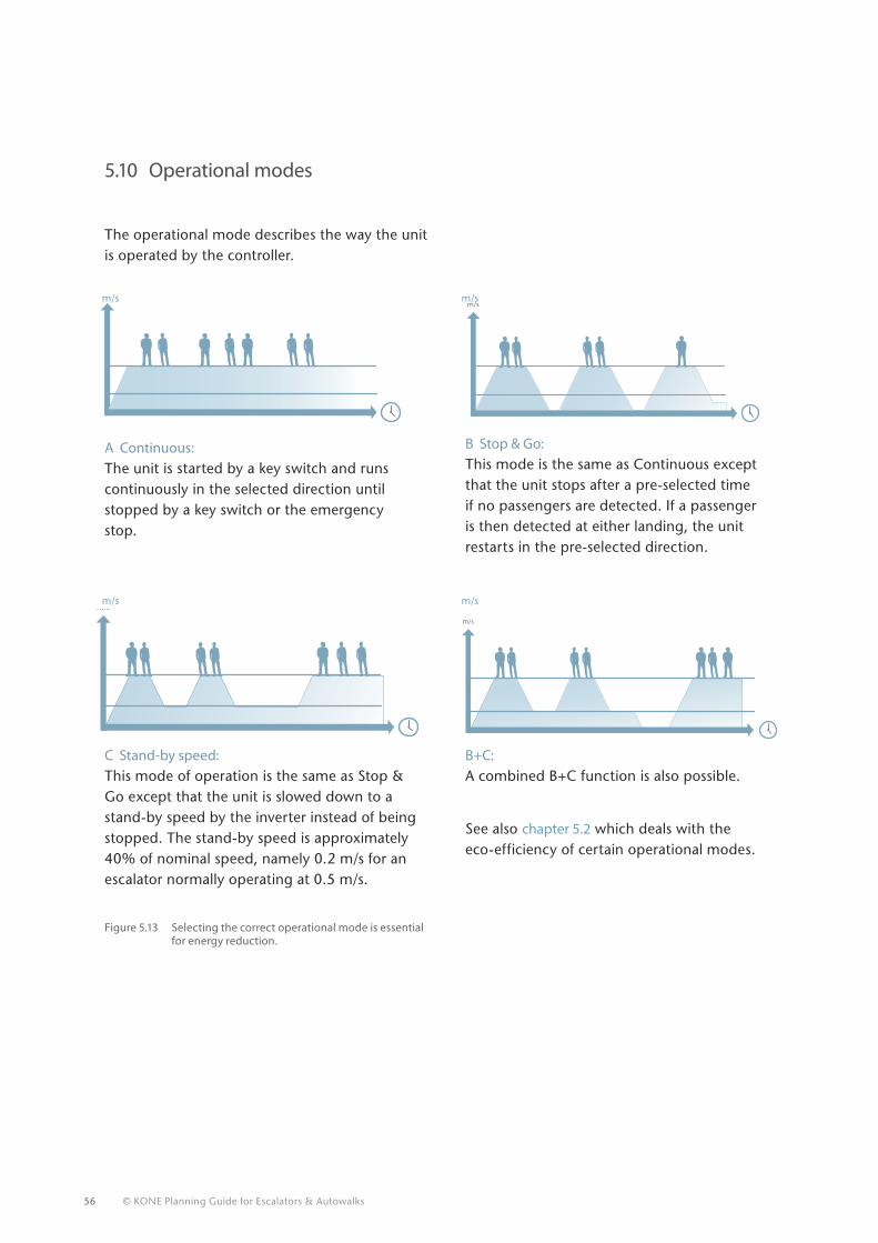
5.10 Operational modes
The operational mode describes the way the unit is operated by the controller.
m/sm/s
Figure 5.13 Selecting the correct operational mode is essential for energy reduction.
m/s
A Continuous: The unit is started by a key switch and runs continuously in the selected direction until stopped by a key switch or the emergency stop.
B Stop & Go: This mode is the same as Continuous except that the unit stops after a pre-selected time if no passengers are detected. If a passenger is then detected at either landing, the unit restarts in the pre-selected direction.
C Stand-by speed: This mode of operation is the same as Stop & Go except that the unit is slowed down to a stand-by speed by the inverter instead of being stopped. The stand-by speed is approximately 40% of nominal speed, namely 0.2 m/s for an escalator normally operating at 0.5 m/s.
B+C: A combined B+C function is also possible.
See also chapter 5.2 which deals with the eco-efficiency of certain operational modes.
m/s
m/s
m/s
m/s
m/s
© KONE Planning Guide for Escalators & Autowalks 57
15
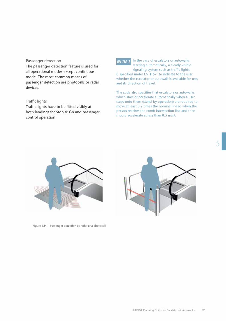
Passenger detectionThe passenger detection feature is used for all operational modes except continuous mode. The most common means of passenger detection are photocells or radar devices.
Traffic lightsTraffic lights have to be fitted visibly at both landings for Stop & Go and passenger control operation.
In the case of escalators or autowalks starting automatically, a clearly visible signaling system such as traffic lights
is specified under EN 115-1 to indicate to the user whether the escalator or autowalk is available for use, and its direction of travel.
The code also specifies that escalators or autowalks which start or accelerate automatically when a user steps onto them (stand-by operation) are required to move at least 0.2 times the nominal speed when the person reaches the comb intersection line and then should accelerate at less than 0.5 m/s².
Figure 5.14 Passenger detection by radar or a photocell
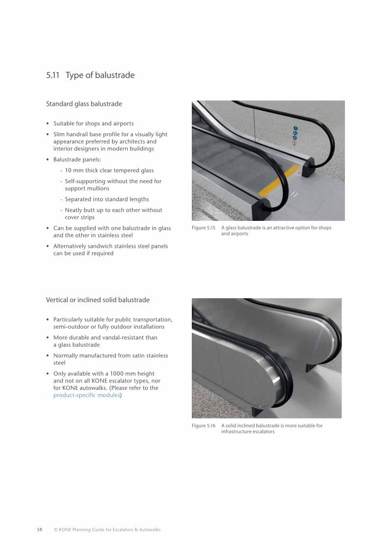
58 © KONE Planning Guide for Escalators & Autowalks
5.11 Type of balustrade
Standard glass balustrade
• Suitable for shops and airports
• Slim handrail base profile for a visually light appearance preferred by architects and interior designers in modern buildings
• Balustrade panels:
- 10 mm thick clear tempered glass
- Self-supporting without the need for support mullions
- Separated into standard lengths
- Neatly butt up to each other without cover strips
• Can be supplied with one balustrade in glass and the other in stainless steel
• Alternatively sandwich stainless steel panels can be used if required
Vertical or inclined solid balustrade
• Particularly suitable for public transportation, semi-outdoor or fully outdoor installations
• More durable and vandal-resistant than a glass balustrade
• Normally manufactured from satin stainless steel
• Only available with a 1000 mm height and not on all KONE escalator types, nor for KONE autowalks. (Please refer to the product-specific modules)
Figure 5.15 A glass balustrade is an attractive option for shops and airports
Figure 5.16 A solid inclined balustrade is more suitable for infrastructure escalators
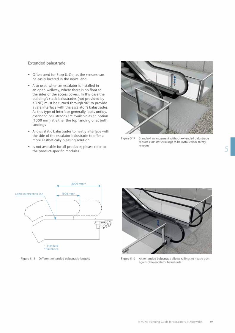
© KONE Planning Guide for Escalators & Autowalks 59
15
Extended balustrade
• Often used for Stop & Go, as the sensors can be easily located in the newel end
• Also used when an escalator is installed in an open wellway, where there is no floor to the sides of the access covers. In this case the building’s static balustrades (not provided by KONE) must be turned through 90° to provide a safe interface with the escalator’s balustrades. As this type of interface generally looks untidy, extended balustrades are available as an option (1000 mm) at either the top landing or at both landings
• Allows static balustrades to neatly interface with the side of the escalator balustrade to offer a more aesthetically pleasing solution
• Is not available for all products; please refer to the product-specific modules.
Figure 5.17 Standard arrangement without extended balustrade requires 90° static railings to be installed for safety reasons
Figure 5.19 An extended balustrade allows railings to neatly butt against the escalator balustrade
Figure 5.18 Different extended balustrade lengths
1000 mm*Comb intersection line
2000 mm**
* Standard**Extended
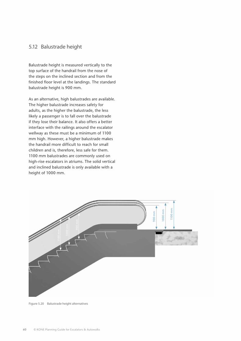
60 © KONE Planning Guide for Escalators & Autowalks
5.12 Balustrade height
Balustrade height is measured vertically to the top surface of the handrail from the nose of the steps on the inclined section and from the finished floor level at the landings. The standard balustrade height is 900 mm.
As an alternative, high balustrades are available. The higher balustrade increases safety for adults, as the higher the balustrade, the less likely a passenger is to fall over the balustrade if they lose their balance. It also offers a better interface with the railings around the escalator wellway as these must be a minimum of 1100 mm high. However, a higher balustrade makes the handrail more difficult to reach for small children and is, therefore, less safe for them. 1100 mm balustrades are commonly used on high-rise escalators in atriums. The solid vertical and inclined balustrade is only available with a height of 1000 mm.
900
mm
900
mm 10
00
mm
100
0 m
m
110
0 m
m
110
0 m
m
Figure 5.20 Balustrade height alternatives
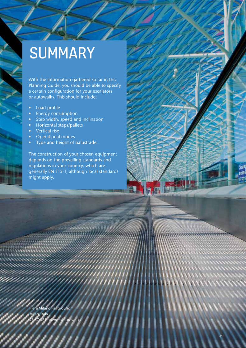
sUmmARyWith the information gathered so far in this Planning Guide, you should be able to specify a certain configuration for your escalators or autowalks. This should include:
• Load profile• Energy consumption• Step width, speed and inclination• Horizontal steps/pallets• Vertical rise• Operational modes• Type and height of balustrade.
The construction of your chosen equipment depends on the prevailing standards and regulations in your country, which are generally EN 115-1, although local standards might apply.
61
Fiera Milano FairgroundMilan, Italy28 KONE horizontal autowalks
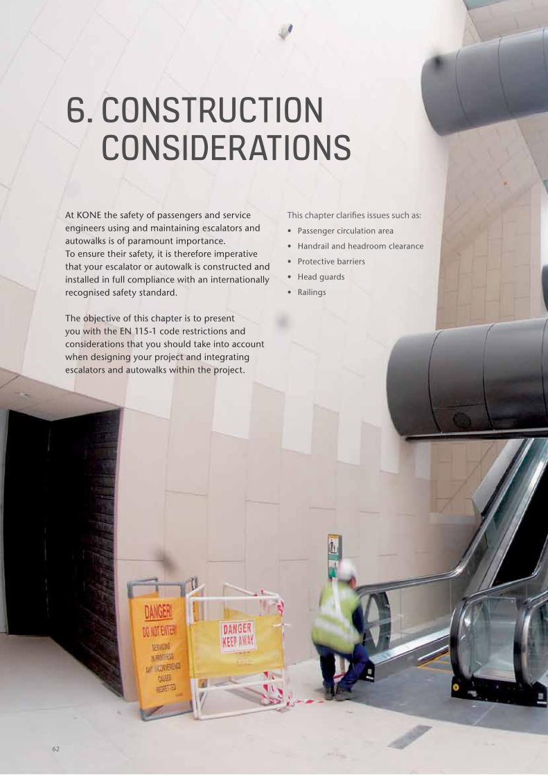
6. cONsTRUcTION cONsIDERATIONs
At KONE the safety of passengers and service engineers using and maintaining escalators and autowalks is of paramount importance. To ensure their safety, it is therefore imperative that your escalator or autowalk is constructed and installed in full compliance with an internationally recognised safety standard.
The objective of this chapter is to present you with the EN 115-1 code restrictions and considerations that you should take into account when designing your project and integrating escalators and autowalks within the project.
This chapter clarifies issues such as:
• Passenger circulation area
• Handrail and headroom clearance
• Protective barriers
• Head guards
• Railings
62
1
1
1
1
1
1
1
1
1
1
1
2
3
4
5
6
7
8
9
1063
Bras Basah stationSingapore
12 KONE escalators
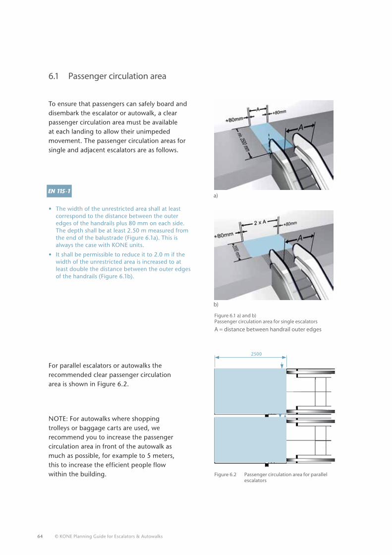
64 © KONE Planning Guide for Escalators & Autowalks
a)
b)
6.1 Passenger circulation area
To ensure that passengers can safely board and disembark the escalator or autowalk, a clear passenger circulation area must be available at each landing to allow their unimpeded movement. The passenger circulation areas for single and adjacent escalators are as follows.
• The width of the unrestricted area shall at least correspond to the distance between the outer edges of the handrails plus 80 mm on each side. The depth shall be at least 2.50 m measured from the end of the balustrade (Figure 6.1a). This is always the case with KONE units.
• It shall be permissible to reduce it to 2.0 m if the width of the unrestricted area is increased to at least double the distance between the outer edges of the handrails (Figure 6.1b).
A = distance between handrail outer edges
NOTE: For autowalks where shopping trolleys or baggage carts are used, we recommend you to increase the passenger circulation area in front of the autowalk as much as possible, for example to 5 meters, this to increase the efficient people flow within the building.
Figure 6.1 a) and b) Passenger circulation area for single escalators
Figure 6.2 Passenger circulation area for parallel escalators
For parallel escalators or autowalks the recommended clear passenger circulation area is shown in Figure 6.2.
2500
Column
Column
Unrestricted area
Unrestricted area
80 m
m80
mm
80 m
m
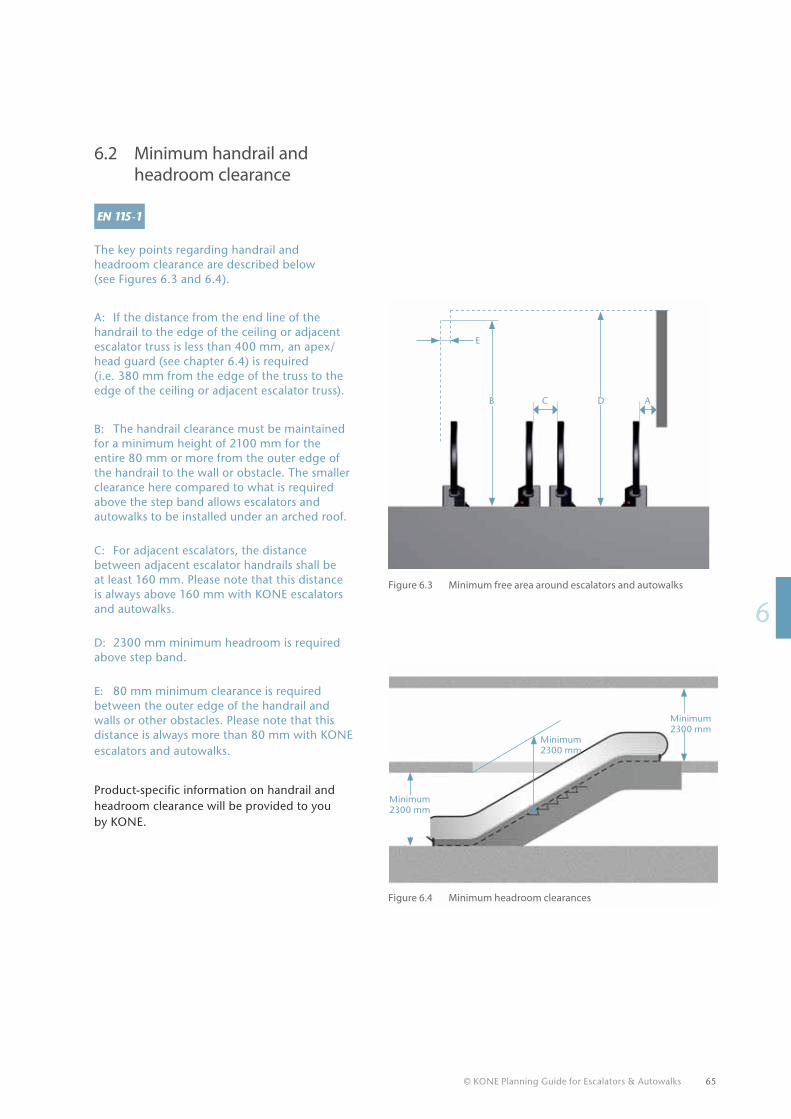
© KONE Planning Guide for Escalators & Autowalks 65
16
The key points regarding handrail and headroom clearance are described below (see Figures 6.3 and 6.4).
A: If the distance from the end line of the handrail to the edge of the ceiling or adjacent escalator truss is less than 400 mm, an apex/head guard (see chapter 6.4) is required (i.e. 380 mm from the edge of the truss to the edge of the ceiling or adjacent escalator truss).
B: The handrail clearance must be maintained for a minimum height of 2100 mm for the entire 80 mm or more from the outer edge of the handrail to the wall or obstacle. The smaller clearance here compared to what is required above the step band allows escalators and autowalks to be installed under an arched roof.
C: For adjacent escalators, the distance between adjacent escalator handrails shall be at least 160 mm. Please note that this distance is always above 160 mm with KONE escalators and autowalks.
D: 2300 mm minimum headroom is required above step band.
E: 80 mm minimum clearance is required between the outer edge of the handrail and walls or other obstacles. Please note that this distance is always more than 80 mm with KONE escalators and autowalks.
Product-specific information on handrail and headroom clearance will be provided to you by KONE.
Figure 6.4 Minimum headroom clearances
Figure 6.3 Minimum free area around escalators and autowalks
Minimum 2300 mm
Minimum 2300 mm
E
CB D A
6.2 Minimum handrail and headroom clearance
Minimum 2300 mm
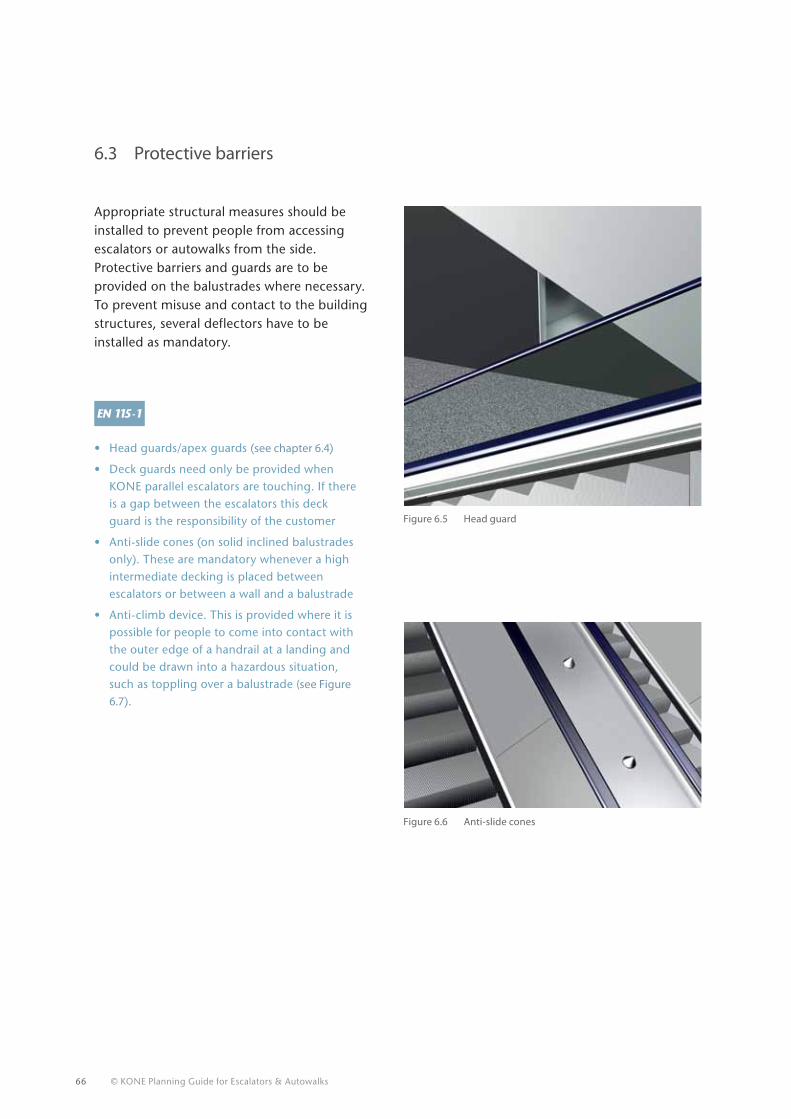
66 © KONE Planning Guide for Escalators & Autowalks
6.3 Protective barriers
Appropriate structural measures should be installed to prevent people from accessing escalators or autowalks from the side. Protective barriers and guards are to be provided on the balustrades where necessary. To prevent misuse and contact to the building structures, several deflectors have to be installed as mandatory.
• Head guards/apex guards (see chapter 6.4)
• Deck guards need only be provided when KONE parallel escalators are touching. If there is a gap between the escalators this deck guard is the responsibility of the customer
• Anti-slide cones (on solid inclined balustrades only). These are mandatory whenever a high intermediate decking is placed between escalators or between a wall and a balustrade
• Anti-climb device. This is provided where it is possible for people to come into contact with the outer edge of a handrail at a landing and could be drawn into a hazardous situation, such as toppling over a balustrade (see Figure 6.7).
Figure 6.5 Head guard
Figure 6.6 Anti-slide cones
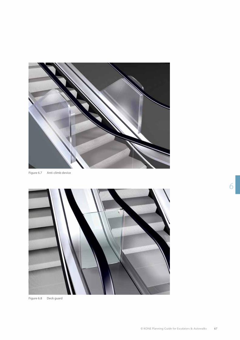
© KONE Planning Guide for Escalators & Autowalks 67
16
Figure 6.7 Anti-climb device
Figure 6.8 Deck guard
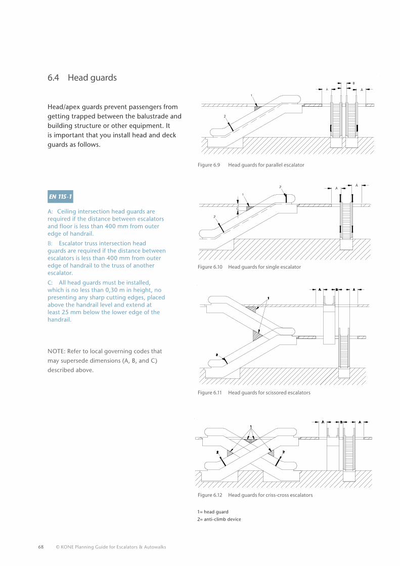
68 © KONE Planning Guide for Escalators & Autowalks
6.4 Head guards
Head/apex guards prevent passengers from getting trapped between the balustrade and building structure or other equipment. It is important that you install head and deck guards as follows.
A: Ceiling intersection head guards are required if the distance between escalators and floor is less than 400 mm from outer edge of handrail.
B: Escalator truss intersection head guards are required if the distance between escalators is less than 400 mm from outer edge of handrail to the truss of another escalator.
C: All head guards must be installed, which is no less than 0,30 m in height, no presenting any sharp cutting edges, placed above the handrail level and extend at least 25 mm below the lower edge of the handrail.
Figure 6.9 Head guards for parallel escalator
Figure 6.10 Head guards for single escalator
Figure 6.11 Head guards for scissored escalators
Figure 6.12 Head guards for criss-cross escalators
NOTE: Refer to local governing codes that
may supersede dimensions (A, B, and C)
described above.
A1
A
22
B
A
1
2
5021202(2009-07)
AB
1= head guard
2= anti-climb device
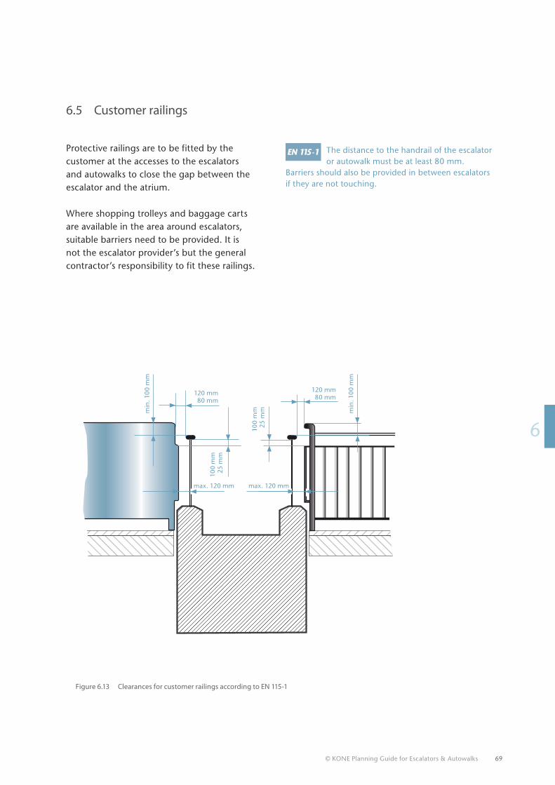
© KONE Planning Guide for Escalators & Autowalks 69
16
The distance to the handrail of the escalator or autowalk must be at least 80 mm.
Barriers should also be provided in between escalators if they are not touching.
6.5 Customer railings
Protective railings are to be fitted by the customer at the accesses to the escalators and autowalks to close the gap between the escalator and the atrium.
Where shopping trolleys and baggage carts are available in the area around escalators, suitable barriers need to be provided. It is not the escalator provider’s but the general contractor’s responsibility to fit these railings.
Figure 6.13 Clearances for customer railings according to EN 115-1
100
mm
25 m
m
100
mm
25 m
mmin
. 10
0 m
m
min
. 10
0 m
m
120 mm80 mm
120 mm80 mm
max. 120 mm max. 120 mm
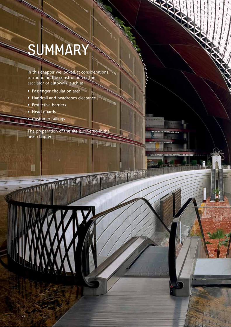
© KONE Planning Guide for Escalators & Autowalks
In this chapter we looked at considerations surrounding the construction of the escalator or autowalk, such as:
• Passenger circulation area
• Handrail and headroom clearance
• Protective barriers
• Head guards
• Customer railings
The preparation of the site is covered in the next chapter.
sUmmARy
70
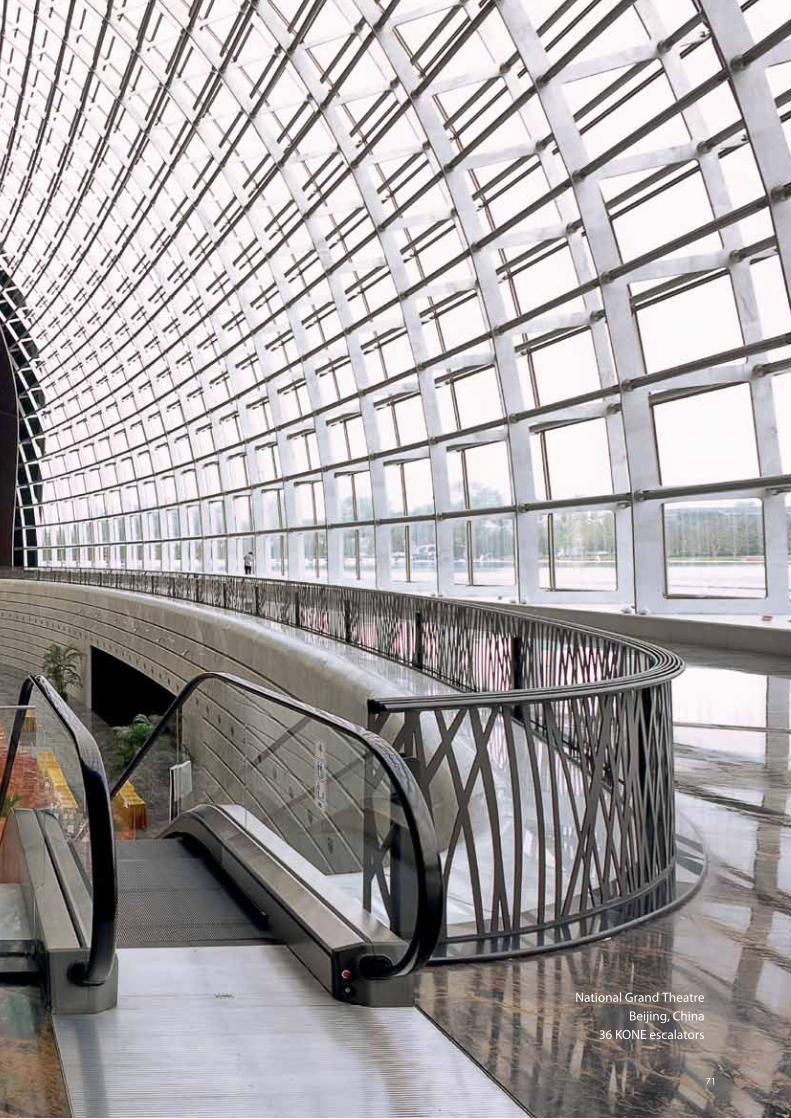
© KONE Planning Guide for Escalators & Autowalks
1
1
1
1
1
1
1
1
1
1
1
2
3
4
5
6
7
8
9
1071
National Grand TheatreBeijing, China
36 KONE escalators
© KONE Planning Guide for Escalators & Autowalks 72

© KONE Planning Guide for Escalators & Autowalks
1
1
1
1
1
1
1
1
1
1
1
2
3
4
5
6
7
8
9
10
7. Preparing the site
7. PREPARING ThE sITE
Modern escalators and autowalks contain a lot of vulnerable electrical and electronic components. If the storage and working areas are not clean, dry and protected from the weather, the equipment can get ruined, even before it is installed. It is therefore vital that the building site is thoroughly prepared in advance before the escalator or autowalk arrives at the site. Ideally,all discussions surrounding site preparation should take place prior to tender. This ensures that both parties are clear on who is responsible for what areas of the installation procedure. In addition the right protection of our products needs to be in place after installation and before final assembly and commissioning.
Also bear in mind that every installation is different. For some installations, additional requirements to the standard ones presented here may apply. These should be discussed during site visits. The building contractor also benefits from these discussions as disagreements over areas of responsibility are avoided, thus ensuring that the project proceeds smoothly within budget and without delays.
Basically the building contractor needs to take responsibility for the following:
• Prepare the mountings – the building needs to be able to resist the weight of the escalator, which can be between 4 and 10 tons, depending on the rise
• Respect the dimensions on KONE drawings – tolerances of KONE layout drawings are +/- 20 mm
• Levelling accuracy of floor – finish floor level markings on each floor are required close to the escalator shaft
• Electrical requirements as explained in chapter 7.5
• For a fully outdoor escalator, a pump or drainage provided by the customer is necessary at the bottom part of the escalator to evacuate water.
73
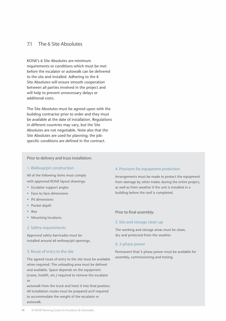
74 © KONE Planning Guide for Escalators & Autowalks
7.1 The 6 Site Absolutes
KONE’s 6 Site Absolutes are minimum requirements or conditions which must be met before the escalator or autowalk can be delivered to the site and installed. Adhering to the 6 Site Absolutes will ensure smooth cooperation between all parties involved in the project and will help to prevent unnecessary delays oradditional costs.
The Site Absolutes must be agreed upon with the building contractor prior to order and they must be available at the date of installation. Regulations in different countries may vary, but the Site Absolutes are not negotiable. Note also that the Site Absolutes are used for planning; the job-specific conditions are defined in the contract.
Prior to delivery and truss installation:
1. Wellway/pit construction
All of the following items must comply
with approved KONE layout drawings:
• Escalator support angles
• Face-to-face dimensions
• Pit dimensions
• Pocket depth
• Rise
• Mounting locations.
2. Safety requirements
Approved safety barricades must be
installed around all wellway/pit openings.
3. Route of entry to the site
The agreed route of entry to the site must be available
when required. The unloading area must be defined
and available. Space depends on the equipment
(crane, forklift, etc.) required to remove the escalator
or
autowalk from the truck and hoist it into final position.
All installation routes must be prepared as/if required
to accommodate the weight of the escalator or
autowalk.
Prior to final assembly:
5. Site and storage clean-up
The working and storage areas must be clean,
dry and protected from the weather.
6. 3-phase power
Permanent final 3-phase power must be available for
assembly, commissioning and testing.
4. Provision for equipment protection
Arrangements must be made to protect the equipment
from damage by other trades during the entire project,
as well as from weather if the unit is installed in a
building before the roof is completed.
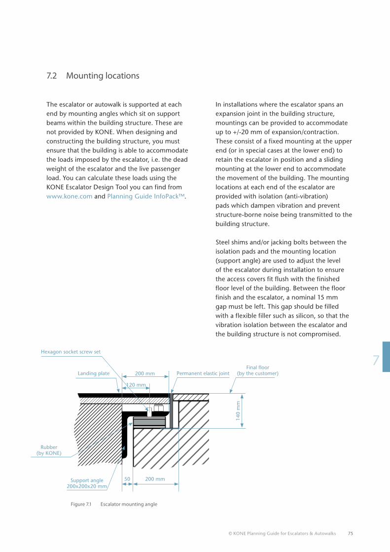
© KONE Planning Guide for Escalators & Autowalks 75
17
7.2 Mounting locations
The escalator or autowalk is supported at each end by mounting angles which sit on support beams within the building structure. These are not provided by KONE. When designing and constructing the building structure, you must ensure that the building is able to accommodate the loads imposed by the escalator, i.e. the dead weight of the escalator and the live passenger load. You can calculate these loads using the KONE Escalator Design Tool you can find from www.kone.com and Planning Guide InfoPack™.
In installations where the escalator spans an expansion joint in the building structure, mountings can be provided to accommodate up to +/-20 mm of expansion/contraction. These consist of a fixed mounting at the upper end (or in special cases at the lower end) to retain the escalator in position and a sliding mounting at the lower end to accommodate the movement of the building. The mounting locations at each end of the escalator are provided with isolation (anti-vibration) pads which dampen vibration and prevent structure-borne noise being transmitted to the building structure.
Steel shims and/or jacking bolts between the isolation pads and the mounting location (support angle) are used to adjust the level of the escalator during installation to ensure the access covers fit flush with the finished floor level of the building. Between the floor finish and the escalator, a nominal 15 mm gap must be left. This gap should be filled with a flexible filler such as silicon, so that the vibration isolation between the escalator and the building structure is not compromised.
Figure 7.1 Escalator mounting angle
Final floor (by the customer)Permanent elastic jointLanding plate
Hexagon socket screw set
Support angle 200x200x20 mm
140
mm
120 mm
50 200 mm
200 mm
Rubber (by KONE)
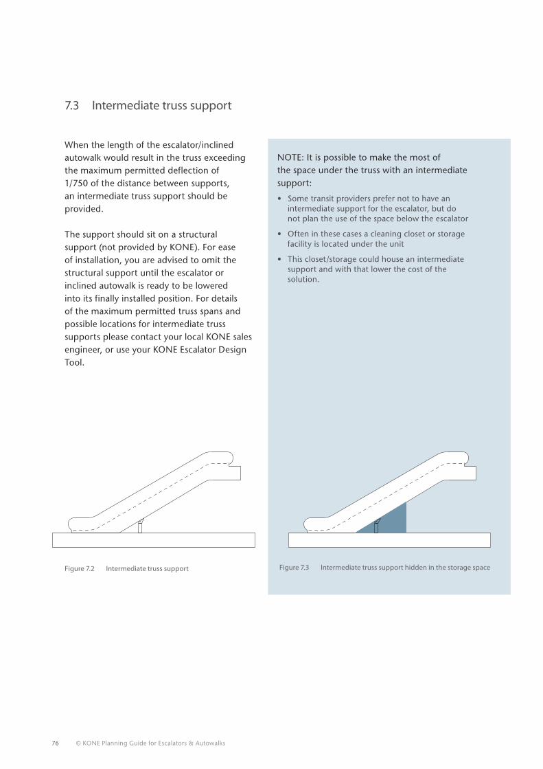
76 © KONE Planning Guide for Escalators & Autowalks
7.3 Intermediate truss support
When the length of the escalator/inclined autowalk would result in the truss exceeding the maximum permitted deflection of 1/750 of the distance between supports, an intermediate truss support should be provided.
The support should sit on a structural support (not provided by KONE). For ease of installation, you are advised to omit the structural support until the escalator or inclined autowalk is ready to be lowered into its finally installed position. For details of the maximum permitted truss spans and possible locations for intermediate truss supports please contact your local KONE sales engineer, or use your KONE Escalator Design Tool.
NOTE: It is possible to make the most of the space under the truss with an intermediate support:
• Some transit providers prefer not to have an intermediate support for the escalator, but do not plan the use of the space below the escalator
• Often in these cases a cleaning closet or storage facility is located under the unit
• This closet/storage could house an intermediate support and with that lower the cost of the solution.
Figure 7.3 Intermediate truss support hidden in the storage spaceFigure 7.2 Intermediate truss support
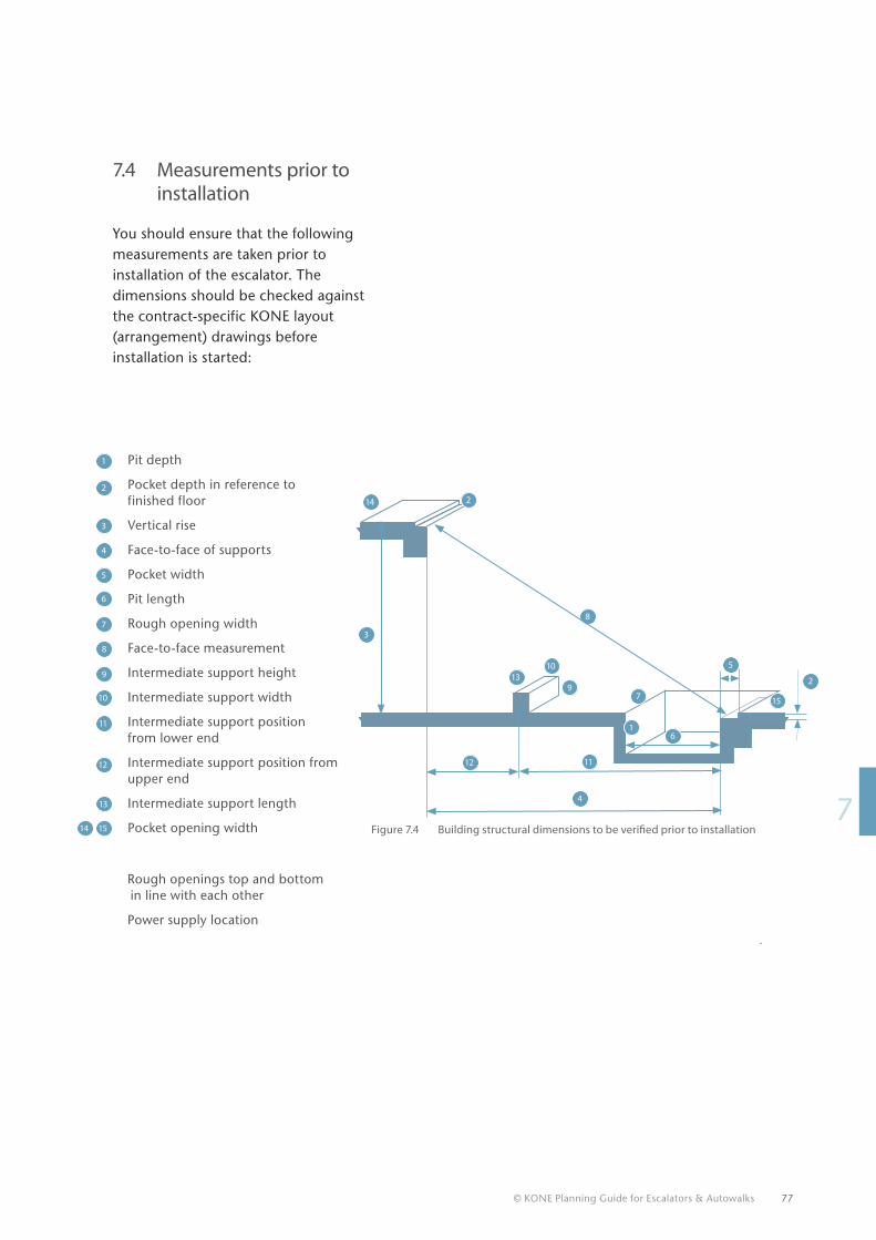
© KONE Planning Guide for Escalators & Autowalks 77
17
7.4 Measurements prior to installation
You should ensure that the following measurements are taken prior to installation of the escalator. The dimensions should be checked against the contract-specific KONE layout (arrangement) drawings before installation is started:
Figure 7.4 Building structural dimensions to be verified prior to installation
Rough openings top and bottom in line with each other
Power supply location
Pit depth
Pocket depth in reference to finished floor
Vertical rise
Face-to-face of supports
Pocket width
Pit length
Rough opening width
Face-to-face measurement
Intermediate support height
Intermediate support width
Intermediate support position from lower end
Intermediate support position from upper end
Intermediate support length
Pocket opening width1514
13
12
11
10
9
8
7
6
5
4
3
2
1
4
61
2
3
2
5
7
8
9
10
1112
13
14
15
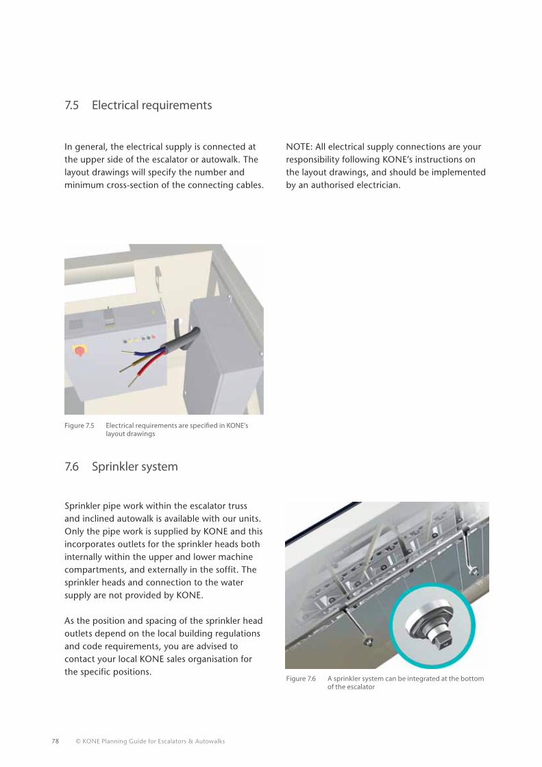
78 © KONE Planning Guide for Escalators & Autowalks
7.5 Electrical requirements
In general, the electrical supply is connected at the upper side of the escalator or autowalk. The layout drawings will specify the number and minimum cross-section of the connecting cables.
7.6 Sprinkler system
Sprinkler pipe work within the escalator truss and inclined autowalk is available with our units. Only the pipe work is supplied by KONE and this incorporates outlets for the sprinkler heads both internally within the upper and lower machine compartments, and externally in the soffit. The sprinkler heads and connection to the water supply are not provided by KONE.
As the position and spacing of the sprinkler head outlets depend on the local building regulations and code requirements, you are advised to contact your local KONE sales organisation for the specific positions.
NOTE: All electrical supply connections are your responsibility following KONE’s instructions on the layout drawings, and should be implemented by an authorised electrician.
Figure 7.5 Electrical requirements are specified in KONE's layout drawings
Figure 7.6 A sprinkler system can be integrated at the bottom of the escalator
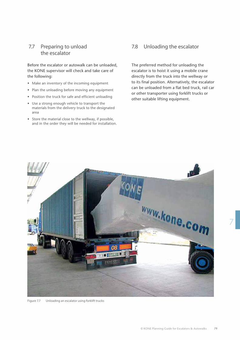
© KONE Planning Guide for Escalators & Autowalks 79
17
7.7 Preparing to unload the escalator
Before the escalator or autowalk can be unloaded, the KONE supervisor will check and take care of the following:
• Make an inventory of the incoming equipment
• Plan the unloading before moving any equipment
• Position the truck for safe and efficient unloading
• Use a strong enough vehicle to transport the materials from the delivery truck to the designated area
• Store the material close to the wellway, if possible, and in the order they will be needed for installation.
7.8 Unloading the escalator
The preferred method for unloading the escalator is to hoist it using a mobile crane directly from the truck into the wellway or to its final position. Alternatively, the escalator can be unloaded from a flat bed truck, rail car or other transporter using forklift trucks or other suitable lifting equipment.
Figure 7.7 Unloading an escalator using forklift trucks
© KONE Planning Guide for Escalators & Autowalks 80
© KONE Planning Guide for Escalators & Autowalks
1
1
1
1
1
1
1
1
1
1
1
2
3
4
5
6
7
8
9
10
SUMMARyThe site has been prepared in advance, the Site Absolutes have been met, the mounting locations and truss supports are in place, the electrician has performed his work and the escalator or autowalk has been delivered and unloaded. Now it’s time to install your unit.
81
Schiphol AirportAmsterdam, The Netherlands
48 KONE escalators51 KONE autowalks
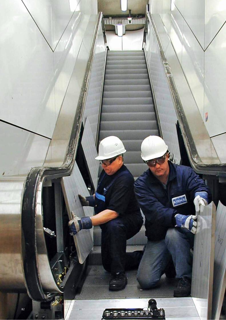
82
18
8. INsTALLING ThE EscALATOR OR AUTOWALK
Escalators and autowalks are physically large, expensive pieces of equipment. It is therefore vital that you thoroughly discuss with KONE the means of installing them into the building and their protection following installation. The actual method of installing an escalator varies from site to site. However, it does tend to be a variation of one of these three basic methods:
• Installation in one complete section by mobile/site tower crane directly into position
• Installation through the building in one complete section
• Installation through the building in two or more sections due to site access restrictions and high rise.
These are explained in detail in this chapter, along with other factors to take into consideration during installation, and how best to protect your escalator or autowalk after it has been installed.
For all installation it is important to plan ahead, to define the most efficient and safe installation method and to minimise the disruption of other trades on site.
© KONE Planning Guide for Escalators & Autowalks 83
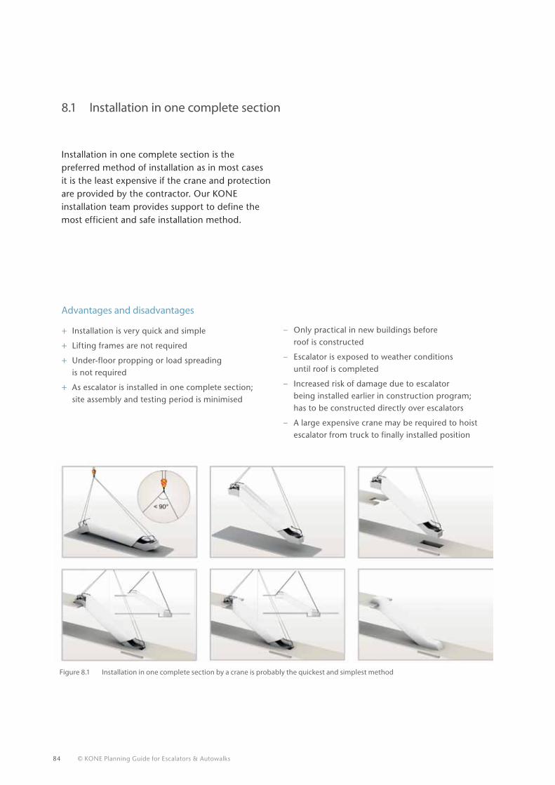
84 © KONE Planning Guide for Escalators & Autowalks
Advantages and disadvantages
+ Installation is very quick and simple
+ Lifting frames are not required
+ Under-floor propping or load spreading is not required
+ As escalator is installed in one complete section; site assembly and testing period is minimised
8.1 Installation in one complete section
Figure 8.1 Installation in one complete section by a crane is probably the quickest and simplest method
– Only practical in new buildings before roof is constructed
– Escalator is exposed to weather conditions until roof is completed
– Increased risk of damage due to escalator being installed earlier in construction program; has to be constructed directly over escalators
– A large expensive crane may be required to hoist escalator from truck to finally installed position
Installation in one complete section is the preferred method of installation as in most cases it is the least expensive if the crane and protection are provided by the contractor. Our KONE installation team provides support to define the most efficient and safe installation method.
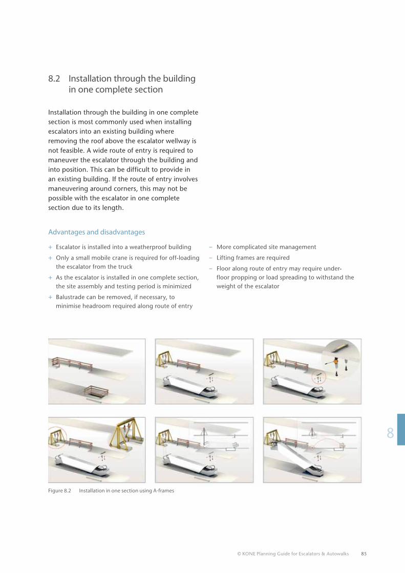
© KONE Planning Guide for Escalators & Autowalks 85
18
8.2 Installation through the building in one complete section
Installation through the building in one complete section is most commonly used when installing escalators into an existing building where removing the roof above the escalator wellway is not feasible. A wide route of entry is required to maneuver the escalator through the building and into position. This can be difficult to provide in an existing building. If the route of entry involves maneuvering around corners, this may not be possible with the escalator in one complete section due to its length.
Advantages and disadvantages
+ Escalator is installed into a weatherproof building
+ Only a small mobile crane is required for off-loading the escalator from the truck
+ As the escalator is installed in one complete section, the site assembly and testing period is minimized
+ Balustrade can be removed, if necessary, to minimise headroom required along route of entry
Figure 8.2 Installation in one section using A-frames
– More complicated site management
– Lifting frames are required
– Floor along route of entry may require under-floor propping or load spreading to withstand the weight of the escalator
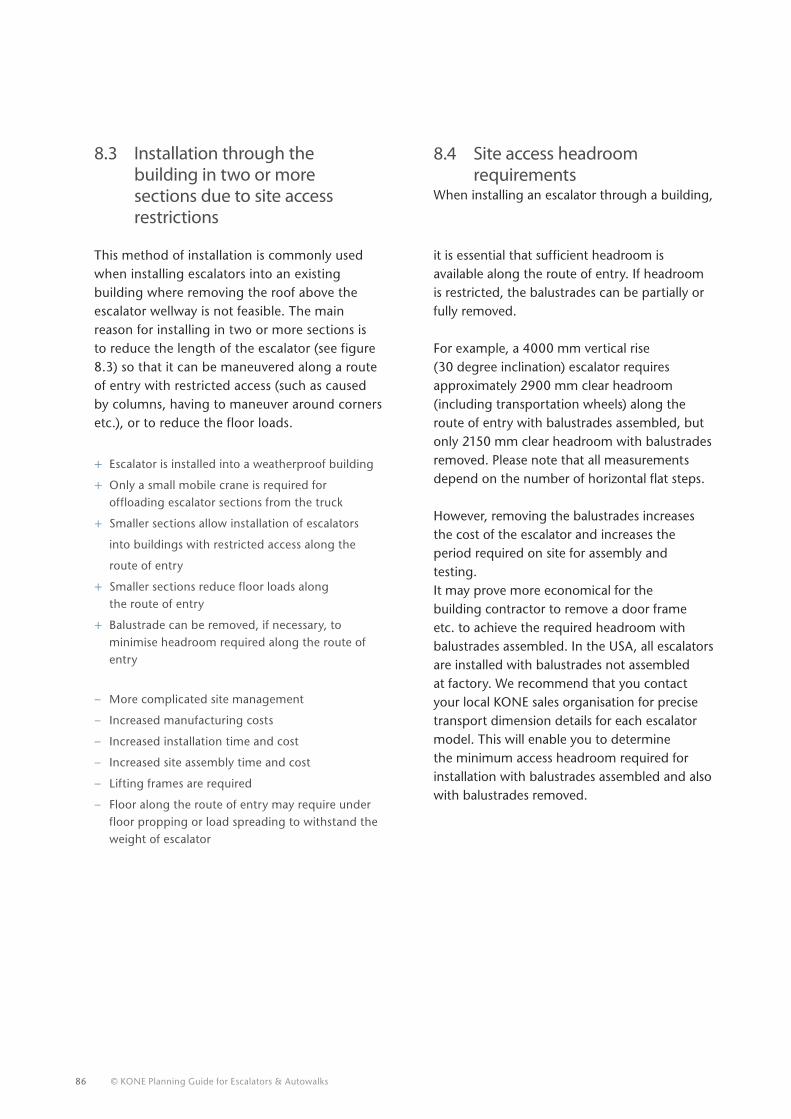
86 © KONE Planning Guide for Escalators & Autowalks
This method of installation is commonly used when installing escalators into an existing building where removing the roof above the escalator wellway is not feasible. The main reason for installing in two or more sections is to reduce the length of the escalator (see figure 8.3) so that it can be maneuvered along a route of entry with restricted access (such as caused by columns, having to maneuver around corners etc.), or to reduce the floor loads.Advantages and disadvantages
+ Escalator is installed into a weatherproof building
+ Only a small mobile crane is required for offloading escalator sections from the truck
+ Smaller sections allow installation of escalators
into buildings with restricted access along the
route of entry
+ Smaller sections reduce floor loads along the route of entry
+ Balustrade can be removed, if necessary, to minimise headroom required along the route of entry
– More complicated site management
– Increased manufacturing costs
– Increased installation time and cost
– Increased site assembly time and cost
– Lifting frames are required
– Floor along the route of entry may require under floor propping or load spreading to withstand the weight of escalator
8.3 Installation through the building in two or more sections due to site access restrictions
8.4 Site access headroom requirements
When installing an escalator through a building,
it is essential that sufficient headroom is available along the route of entry. If headroom is restricted, the balustrades can be partially or fully removed.
For example, a 4000 mm vertical rise (30 degree inclination) escalator requires approximately 2900 mm clear headroom (including transportation wheels) along the route of entry with balustrades assembled, but only 2150 mm clear headroom with balustrades removed. Please note that all measurements depend on the number of horizontal flat steps.
However, removing the balustrades increases the cost of the escalator and increases the period required on site for assembly and testing. It may prove more economical for the building contractor to remove a door frame etc. to achieve the required headroom with balustrades assembled. In the USA, all escalators are installed with balustrades not assembled at factory. We recommend that you contact your local KONE sales organisation for precise transport dimension details for each escalator model. This will enable you to determine the minimum access headroom required for installation with balustrades assembled and also with balustrades removed.
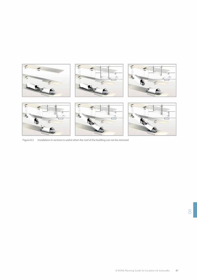
© KONE Planning Guide for Escalators & Autowalks 87
18
Figure 8.3 Installation in sections is useful when the roof of the building can not be removed
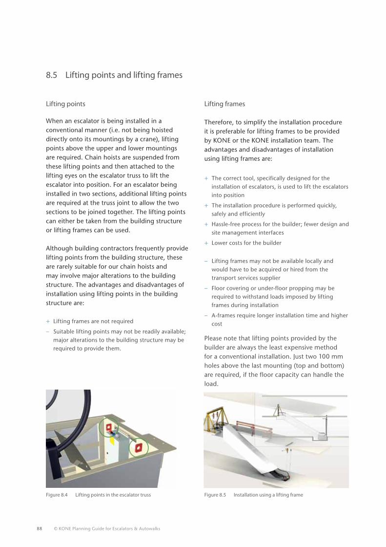
88 © KONE Planning Guide for Escalators & Autowalks
8.5 Lifting points and lifting frames
Lifting points
When an escalator is being installed in a conventional manner (i.e. not being hoisted directly onto its mountings by a crane), lifting points above the upper and lower mountings are required. Chain hoists are suspended from these lifting points and then attached to the lifting eyes on the escalator truss to lift the escalator into position. For an escalator being installed in two sections, additional lifting points are required at the truss joint to allow the two sections to be joined together. The lifting points can either be taken from the building structure or lifting frames can be used.
Although building contractors frequently provide lifting points from the building structure, these are rarely suitable for our chain hoists and may involve major alterations to the building structure. The advantages and disadvantages of installation using lifting points in the building structure are:
+ Lifting frames are not required
– Suitable lifting points may not be readily available; major alterations to the building structure may be required to provide them.
Lifting frames
Therefore, to simplify the installation procedure it is preferable for lifting frames to be provided by KONE or the KONE installation team. The advantages and disadvantages of installation using lifting frames are:
+ The correct tool, specifically designed for the installation of escalators, is used to lift the escalators into position
+ The installation procedure is performed quickly, safely and efficiently
+ Hassle-free process for the builder; fewer design and site management interfaces
+ Lower costs for the builder
– Lifting frames may not be available locally and would have to be acquired or hired from the transport services supplier
– Floor covering or under-floor propping may be required to withstand loads imposed by lifting frames during installation
– A-frames require longer installation time and higher cost
Please note that lifting points provided by the builder are always the least expensive method for a conventional installation. Just two 100 mm holes above the last mounting (top and bottom) are required, if the floor capacity can handle the load.
Figure 8.4 Lifting points in the escalator truss Figure 8.5 Installation using a lifting frame
© KONE Planning Guide for Escalators & Autowalks 89
18
8.6 Protection of escalators and autowalks following installation
Immediately following the installation, it is vital that the escalator or autowalk is suitably protected to prevent it being damaged by water, dust, debris and falling objects etc. If the unit is installed in a building prior to the roof being completed, it will need to be protected against the elements. As an absolute minimum, the complete escalator or autowalk should be wrapped in heavy gauge polyethylene film to protect it from dust and water. As the units are delivered shrink-wrapped in polyethylene film, this should be left in position, where possible, and only removed where necessary to fit transportation wheels or gain access to the lifting eyes. Upon completion of the installation, the polyethylene film can then be repaired with adhesive tape.
Examples of protection that could be used in addition to polyethylene are as follows. The type of protection should be selected to suit the anticipated site conditions on each project:
• Plywood protection to the newel ends at each landing to prevent access onto the step band and balustrades.
• Plywood protection along the full length of the escalator down to outer decking level to prevent damage to the vulnerable balustrades and step band by falling debris and objects.
• Encasing the whole escalator in plywood protection to prevent damage to the vulnerable balustrades, step band and also the truss cladding by falling debris and objects.
On many projects the escalator or autowalk is installed on site for weeks or months before assembly, testing and handover to the customer. During this period, KONE may not have representatives on site full-time. Therefore, as the building contractor will have full-time site representation during this period, it is preferable that they provide the protection and take responsibility for maintaining it until the KONE engineers commence the assembly and testing work.
© KONE Planning Guide for Escalators & Autowalks
SUMMARy After your escalator or autowalk has been successfully installed it will provide safe,efficient service over its long lifetime.
90
© KONE Planning Guide for Escalators & Autowalks
1
1
1
1
1
1
1
1
1
1
1
2
3
4
5
6
7
8
9
1091
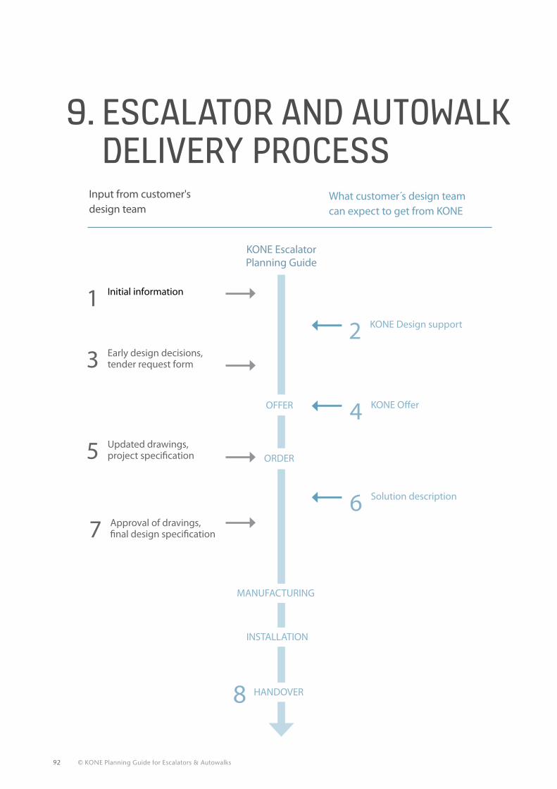
92 © KONE Planning Guide for Escalators & Autowalks
Input from customer's design team
What customer s design team can expect to get from KONE
3 Early design decisions, tender request form
5 Updated drawings, project specification
7 Approval of dravings, final design specification
1 Initial information
2 KONE Design support
4 KONE Offer
6 Solution description
MANUFACTURING
HANDOVER
ORDER
OFFER
INSTALLATION
KONE Escalator Planning Guide
8
9. EscALATOR AND AUTOWALK DELIvERy PROcEss
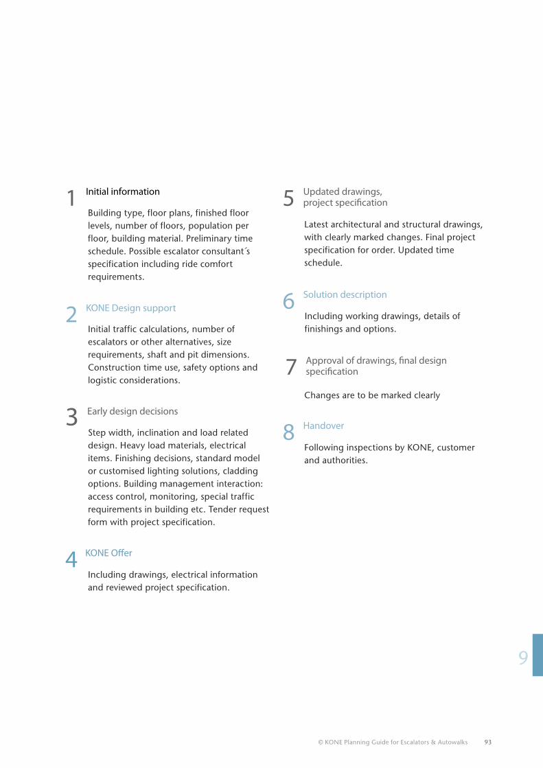
© KONE Planning Guide for Escalators & Autowalks 93
19
1 Initial information
Building type, floor plans, finished floor levels, number of floors, population per floor, building material. Preliminary time schedule. Possible escalator consultant s specification including ride comfort requirements.
2 KONE Design support
Initial traffic calculations, number of escalators or other alternatives, size requirements, shaft and pit dimensions. Construction time use, safety options and logistic considerations.
3 Early design decisions Step width, inclination and load related design. Heavy load materials, electrical items. Finishing decisions, standard model or customised lighting solutions, cladding options. Building management interaction: access control, monitoring, special traffic requirements in building etc. Tender request form with project specification.
4 KONE Offer
Including drawings, electrical information and reviewed project specification.
Latest architectural and structural drawings, with clearly marked changes. Final project specification for order. Updated time schedule.
5 Updated drawings, project specification
Including working drawings, details of finishings and options.
6 Solution description
7 Approval of drawings, final design specification
Changes are to be marked clearly
8 Handover
Following inspections by KONE, customer and authorities.
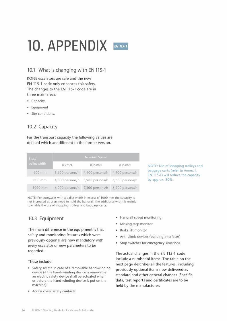
94 © KONE Planning Guide for Escalators & Autowalks
10.3 Equipment
The main difference in the equipment is that safety and monitoring features which were previously optional are now mandatory with every escalator or new parameters to be regarded. These include:
• Safety switch in case of a removable hand-winding device (if the hand-winding device is removable an electric safety device shall be actuated when or before the hand-winding device is put on the machine)
• Access cover safety contacts
10. APPENDIx
KONE escalators are safe and the new EN 115-1 code only enhances this safety.The changes to the EN 115-1 code are in three main areas:
• Capacity
• Equipment
• Site conditions.
10.2 Capacity
For the transport capacity the following values are defined which are different to the former version.
Step/pallet width
Nominal Speed
0.5 m/s 0.65 m/s 0.75 m/s
600 mm 3,600 persons/h 4,400 persons/h 4,900 persons/h
800 mm 4,800 persons/h 5,900 persons/h 6,600 persons/h
1000 mm 6,000 persons/h 7,300 persons/h 8,200 persons/h
NOTE: Use of shopping trolleys and baggage carts (refer to Annex I, EN 115-1) will reduce the capacity by approx. 80%.
10.1 What is changing with EN 115-1
NOTE: For autowalks with a pallet width in excess of 1000 mm the capacity isnot increased as users need to hold the handrail; the additional width is mainly to enable the use of shopping trolleys and baggage carts.
• Handrail speed monitoring
• Missing step monitor
• Brake lift monitor
• Anti-climb devices (building interfaces)
• Stop switches for emergency situations
The actual changes in the EN 115-1 code include a number of items. The table on the next page describes all the features, including previously optional items now delivered as standard and other general changes. Specific data, test reports and certificates are to be held by the manufacturer.
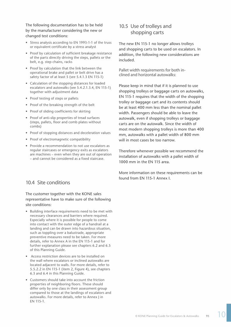
© KONE Planning Guide for Escalators & Autowalks 95
110
The following documentation has to be held by the manufacturer considering the new or changed test conditions:
• Stress analysis according to EN 1993-1-1 of the truss or equivalent certificate by a stress analyst
• Proof by calculation of sufficient breakage resistance of the parts directly driving the steps, pallets or the belt, e.g. step chains, racks
• Proof by calculation that the link between the operational brake and pallet or belt drive has a safety factor of at least 5 (see 5.4.1.3 EN 115-1)
• Calculation of the stopping distances for loaded escalators and autowalks (see 5.4.2.1.3.4, EN 115-1) together with adjustment data
• Proof testing of steps or pallets
• Proof of the breaking strength of the belt
• Proof of sliding coefficients for skirting
• Proof of anti-slip properties of tread surfaces (steps, pallets, floor and comb plates without combs)
• Proof of stopping distances and deceleration values
• Proof of electromagnetic compatibility
• Provide a recommendation to not use escalators as regular staircases or emergency exits as escalators are machines – even when they are out of operation – and cannot be considered as a fixed staircase.
10.4 Site conditions The customer together with the KONE sales representative have to make sure of the following site conditions:
• Building interface requirements need to be met with necessary clearances and barriers where required. Especially where it is possible for people to come into contact with the outer edge of a handrail at a landing and can be drawn into hazardous situation, such as toppling over a balustrade, appropriate preventive measures need to be taken. For more details, refer to Annex A in the EN 115-1 and for further explanation please see chapters 6.2 and 6.5 of this Planning Guide.
• Access restriction devices are to be installed on the wall where escalators or inclined autowalks are located adjacent to walls. For more details, refer to 5.5.2.2 in EN 115-1 (item 2, Figure 4), see chapters 6.3 and 6.4 in this Planning Guide.
• Customers should take into account the friction properties of neighboring floors. These should differ only by one class in their assessment group compared to those at the landings of escalators and autowalks. For more details, refer to Annex J in EN 115-1.
10.5 Use of trolleys and shopping carts
The new EN 115-1 no longer allows trolleys and shopping carts to be used on escalators. In addition, the following new considerations are included. Pallet width requirements for both in-clined and horizontal autowalks: Please keep in mind that if it is planned to use shopping trolleys or baggage carts on autowalks, EN 115-1 requires that the width of the shopping trolley or baggage cart and its contents should be at least 400 mm less than the nominal pallet width. Passengers should be able to leave the autowalk, even if shopping trolleys or baggage carts are on the autowalk. Since the width of most modern shopping trolleys is more than 400 mm, autowalks with a pallet width of 800 mm will in most cases be too narrow.
Therefore whenever possible we recommend the installation of autowalks with a pallet width of 1000 mm in the EN 115 area. More information on these requirements can be found from EN 115-1 Annex I.
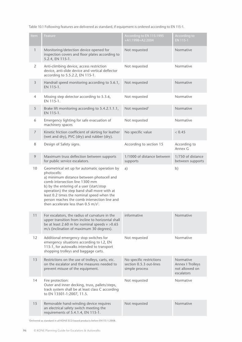
96 © KONE Planning Guide for Escalators & Autowalks
Item Feature According to EN 115:1995 +A1:1998+A2:2004
According to EN 115-1
1 Monitoring/detection device opened for inspection covers and floor plates according to 5.2.4, EN 115-1.
Not requested Normative
2 Anti-climbing device, access restriction device, anti-slide device and vertical deflector according to 5.5.2.2, EN 115-1.
Not requested Normative
3 Handrail speed monitoring according to 5.6.1, EN 115-1.
Not requested Normative
4 Missing step detector according to 5.3.6, EN 115-1.
Not requested Normative
5 Brake lift monitoring according to 5.4.2.1.1.1, EN 115-1.
Not requested1 Normative
6 Emergency lighting for safe evacuation of machinery spaces
Not requested Normative
7 Kinetic friction coefficient of skirting for leather (wet and dry), PVC (dry) and rubber (dry).
No specific value < 0.45
8 Design of Safety signs. According to section 15 According to Annex G
9 Maximum truss deflection between supports for public service escalators.
1/1000 of distance between supports
1/750 of distance between supports
10 Geometrical set up for automatic operation by photocells: a) minimum distance between photocell and comb intersection line 1300 mm b) by the entering of a user (start/stop operation) the step band shall move with at least 0.2 times the nominal speed when the person reaches the comb intersection line and then accelerate less than 0.5 m/s2.
a) b)
11 For escalators, the radius of curvature in the upper transition from incline to horizontal shall be at least 2.60 m for nominal speeds v >0.65 m/s (inclination of maximum 30 degrees).
informative Normative
12 Additional emergency stop switches for emergency situations according to I.2, EN 115-1, for autowalks intended to transport shopping trolleys and baggage carts.
Not requested Normative
13 Restrictions on the use of trolleys, carts, etc. on the escalator and the measures needed to prevent misuse of the equipment.
No specific restrictions section 0.5.3 out-lines simple process
Normative Annex I Trolleys not allowed on escalators
14 Fire protection:Outer and inner decking, truss, pallets/steps, track system shall be at least class C according to EN 13501-1:2007, 11.5.
Not requested Normative
15 Removable hand-winding device requires an electrical safety switch meeting the requirements of 5.4.1.4, EN 115-1.
Not requested Normative
Table 10.1 Following features are delivered as standard, if equipment is ordered according to EN 115-1.
1Delivered as standard in all KONE ECO based products before EN115-1:2008.
© KONE Planning Guide for Escalators & Autowalks 97
110
List of figures:
List of tables:Table 3.1 The main transportation characteristics of escalators, autowalks and lifts ....................................................................................................................12
Table 4.1 Traffic capacity calculations according to EN 115-1 ...................................................................................................................................................................16
Table 4.2 Typical configurations for commercial units ................................................................................................................................................................................23
Table 4.3 Typical configurations for infrastructure units ............................................................................................................................................................................23
Table 4.4 Recommended specifications for a semi-outdoor escalator ................................................................................................................................................31
Table 4.5 Recommended specifications for a fully outdoor escalators ................................................................................................................................................31
Table 5.1 Summary of the speeds available with KONE escalators and autowalks .........................................................................................................................49
Table 5.2 The most common vertical rises used in different buildings ................................................................................................................................................54
Table 5.3 Recommended transition radii for escalators .............................................................................................................................................................................55
Table 10.1 Following features are delivered as standard, if equipment is ordered according to EN 115-1. .............................................................................96
Figure 3.1 Escalator components...........................................................................................................................................................................................................................10
Figure 3.2 Horizontal autowalk components ....................................................................................................................................................................................................11
Figure 3.3 Inclined autowalk components .........................................................................................................................................................................................................11
Figure 4.1 Typical people flow in a multi-level shopping centre, showing three major peaks ....................................................................................................19
Figure 4.2 Typical people flow in a 24h metro station with two major peaks .....................................................................................................................................21
Figure 4.3 The outdoor escalator should be covered by a roof to improve passenger safety and convenience. .................................................................29
Figure 5.1 Step chain with outside rollers ..........................................................................................................................................................................................................41
Figure 5.2 Step chain with inside rollers..............................................................................................................................................................................................................41
Figure 5.3 LED skirt spotlighting ............................................................................................................................................................................................................................45
Figure 5.4 Escalator step widths .............................................................................................................................................................................................................................46
Figure 5.5 Horizontal autowalk pallet widths ...................................................................................................................................................................................................47
Figure 5.6 Inclined autowalk pallet widths ........................................................................................................................................................................................................47
Figure 5.7 The nominal speeds for escalators and autowalks ...................................................................................................................................................................48
Figure 5.8 The relationship between inclination angle and overall vertical/horizontal dimensions of escalators. .............................................................50
Figure 5.9 The relationship between inclination angle and overall vertical/horizontal dimensions of inclined autowalks. ...........................................51
Figure 5.10 Horizontal steps/pallets enable a passenger to step safely on and off the escalator. ................................................................................................52
Figure 5.11 Vertical rise and speed of an escalator with two horizontal steps" ....................................................................................................................................52
Figure 5.12 The number of horizontal pallets required for inclined autowalks varies with the speed
and inclination (one horizontal pallet on the top, two horizontal pallets on the bottom picture). ......................................................................53
Figure 5.13 Selecting the correct operational mode is essential for energy reduction. ....................................................................................................................56
Figure 5.14 Passenger detection by radar or a photocell ...............................................................................................................................................................................57
Figure 5.15 A glass balustrade is an attractive option for shops and airports .......................................................................................................................................58
Figure 5.16 A solid inclined balustrade is more suitable for infrastructure escalators .......................................................................................................................58
Figure 5.17 Standard arrangement without extended balustrade requires 90° static railings to be installed for safety reasons ...................................59
Figure 5.18 Different extended balustrade lengths .........................................................................................................................................................................................59
Figure 5.19 An extended balustrade allows railings to neatly butt against the escalator balustrade .........................................................................................59
Figure 5.20 Balustrade height alternatives ...........................................................................................................................................................................................................60
Figure 6.1 Passenger circulation area for single escalators a) and b) .....................................................................................................................................................64
Figure 6.2 Passenger circulation area for parallel escalators ......................................................................................................................................................................64
Figure 6.3 Minimum free area around escalators and autowalks ............................................................................................................................................................65
Figure 6.4 Minimum headroom clearances .......................................................................................................................................................................................................65
Figure 6.5 Head guard ................................................................................................................................................................................................................................................66
Figure 6.6 Anti-slide cones .......................................................................................................................................................................................................................................66
Figure 6.7 Anti-climb device ....................................................................................................................................................................................................................................67
Figure 6.8 Deck guard .................................................................................................................................................................................................................................................67
Figure 6.9 Head guards for parallel escalator....................................................................................................................................................................................................68
Figure 6.10 Head guards for single escalator.......................................................................................................................................................................................................68
Figure 6.11 Head guards for scissored escalators ..............................................................................................................................................................................................68
Figure 6.12 Head guards for criss-cross escalators ............................................................................................................................................................................................68
Figure 6.13 Clearances for customer railings according to EN 115-1 ..........................................................................................................................................................69
Figure 7.1 Escalator mounting angle ....................................................................................................................................................................................................................75
Figure 7.2 Intermediate truss support .................................................................................................................................................................................................................76
Figure 7.3 Intermediate truss support hidden in the storage space .......................................................................................................................................................76
Figure 7.4 Building structural dimensions to be verified prior to installation .....................................................................................................................................77
Figure 7.5 Electrical requirements are specified in KONE's layout drawings ......................................................................................................................................78
Figure 7.6 A sprinkler system can be integrated at the bottom of the escalator ...............................................................................................................................78
Figure 7.7 Unloading an escalator using forklift trucks ................................................................................................................................................................................79
Figure 8.1 Installation in one complete section by a crane is probably the quickest and simplest method ..........................................................................84
Figure 8.2 Installation in one section using A-frames ...................................................................................................................................................................................85
Figure 8.3 Installation in sections is useful when the roof of the building can not be removed ................................................................................................87
Figure 8.4 Lifting points in the escalator truss .................................................................................................................................................................................................88
Figure 8.5 Installation using a lifting frame .......................................................................................................................................................................................................88

98 © KONE Planning Guide for Escalators & Autowalks

© KONE Planning Guide for Escalators & Autowalks 99


![KONE 2011 Architectural Planning Guide[1]](https://static.fdocuments.us/doc/165x107/54401839b1af9ff57a8b45d6/kone-2011-architectural-planning-guide1.jpg)