1 © 2011 Westinghouse Electric Company LLC. All Rights Reserved.Westinghouse Non-Proprietary Class...
16
1 © 2011 Westinghouse Electric Company LLC. All Rights Reserved. Westinghouse Non-Proprietary Class 3 Control Rod Drive System (PRD) Overview ● P. J. Sebastiani ● University of Pittsburgh ME 2120 ● February 7, 2011
-
Upload
ralf-short -
Category
Documents
-
view
218 -
download
0
Transcript of 1 © 2011 Westinghouse Electric Company LLC. All Rights Reserved.Westinghouse Non-Proprietary Class...

1
© 2011 Westinghouse Electric Company LLC. All Rights Reserved.Westinghouse Non-Proprietary Class 3
Control Rod Drive System (PRD) Overview
● P. J. Sebastiani● University of Pittsburgh ME 2120● February 7, 2011
2
© 2011 Westinghouse Electric Company LLC. All Rights Reserved.Westinghouse Non-Proprietary Class 3
Control Rod Drive System (PRD)Agenda
● Purpose of the System● Background● Required Outputs● Initial Conditions● Time-Dependent Boundary Conditions● Required Geometry● Pertinent Physics● Viewable Signals
3
© 2011 Westinghouse Electric Company LLC. All Rights Reserved.Westinghouse Non-Proprietary Class 3
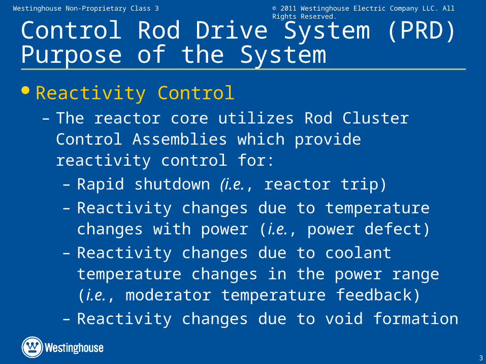
Control Rod Drive System (PRD)Purpose of the SystemReactivity Control
– The reactor core utilizes Rod Cluster Control Assemblies which provide reactivity control for:
– Rapid shutdown (i.e., reactor trip)
– Reactivity changes due to temperature changes with power (i.e., power defect)
– Reactivity changes due to coolant temperature changes in the power range (i.e., moderator temperature feedback)
– Reactivity changes due to void formation

4
© 2011 Westinghouse Electric Company LLC. All Rights Reserved.Westinghouse Non-Proprietary Class 3
Control Rod Drive System (PRD)BackgroundRod Cluster Control Assemblies (RCCAs)
– RCCAs consists of absorber rods attached to a spider connector which, in turn, is connected to a drive shaft.
– RCCA control elements consist of cylindrical neutron absorber rods (control rods).
– The control rods extend the full length of the core when fully inserted.
– The RCCAs are arranged into groups and electrically interconnected so that the entire group moves together.
– Reactivity of the core is changed by raising or lowering a group within the core.

5
© 2011 Westinghouse Electric Company LLC. All Rights Reserved.Westinghouse Non-Proprietary Class 3
Control Rod Drive System (PRD)Background (continued)RCCA Diagram (within Fuel Assembly)
6
© 2011 Westinghouse Electric Company LLC. All Rights Reserved.Westinghouse Non-Proprietary Class 3
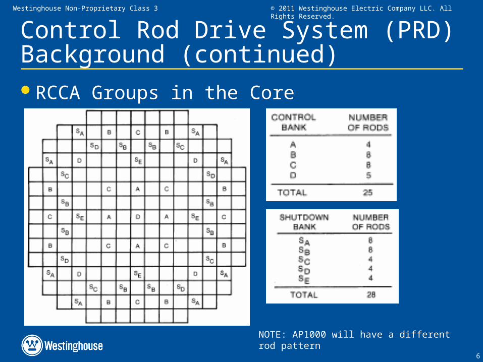
Control Rod Drive System (PRD)Background (continued)RCCA Groups in the Core
NOTE: AP1000 will have a different rod pattern
7
© 2011 Westinghouse Electric Company LLC. All Rights Reserved.Westinghouse Non-Proprietary Class 3
Control Rod Drive System (PRD)Background (continued)Control Rod Drive Mechanism
– The RCCAs are positioned by latch-type magnetic jack control rod drive mechanisms (CRDMs) mounted on the reactor vessel head
– Used to raise and lower the RCCAs (in/out of core)
– Instantly releases RCCAs when necessary for rapid reactor shutdown (i.e., Reactor Trip)
– Latch positions are referred to as “steps”
– Stepping distance: 5/8 inch (in)
– Total rod position indication length: ~230 steps (~144 in)
– Maximum Rods Move Speed: 45 inch/min (72 steps/min)
8
© 2011 Westinghouse Electric Company LLC. All Rights Reserved.Westinghouse Non-Proprietary Class 3
Control Rod Drive System (PRD)Required OutputsRods Move Speed
– Manual Control (default setting): 48 steps/min
– Automatic Control: up to 72 steps/min (see Pertinent Physics Section)
Rods Move Direction– In or Out

9
© 2011 Westinghouse Electric Company LLC. All Rights Reserved.Westinghouse Non-Proprietary Class 3
Control Rod Drive System (PRD)Initial ConditionsControl Scheme
– Automatic or Manual ControlRod Insertion Limits
– Technical Specification Limits on rod position to ensure adequate Shutdown Margin for the core
Rod Position– The current rod position at the start of the simulation
10
© 2011 Westinghouse Electric Company LLC. All Rights Reserved.Westinghouse Non-Proprietary Class 3
Control Rod Drive System (PRD)Time-Dependent Boundary ConditionsCore Average Temperature (TAVG)
– Calculated using cold leg (TCOLD) and hot leg (THOT)
temperature values
– Input to the “Temperature Error” signalReactor Power (2 separate inputs)
– One input from Turbine Impulse Pressure (for Temperature Error calculation)
– Will this be available in PANTHER model?
– One input from Power Range Detector (for Power Mismatch calculation)

11
© 2011 Westinghouse Electric Company LLC. All Rights Reserved.Westinghouse Non-Proprietary Class 3
Control Rod Drive System (PRD)Time-Dependent Boundary Conditions (cont.)
Trip Breaker Setting– i.e., Manual Reactor Trip
– Open or Closed

12
© 2011 Westinghouse Electric Company LLC. All Rights Reserved.Westinghouse Non-Proprietary Class 3
Control Rod Drive System (PRD)Required GeometryControl Rod Pattern
– See Background Section for example

13
© 2011 Westinghouse Electric Company LLC. All Rights Reserved.Westinghouse Non-Proprietary Class 3
Control Rod Drive System (PRD)Pertinent PhysicsTotal Error Calculation

14
© 2011 Westinghouse Electric Company LLC. All Rights Reserved.Westinghouse Non-Proprietary Class 3
Control Rod Drive System (PRD)Pertinent PhysicsRods Move Speed
Deadband
Inward Motion
Total Error (TRef - TAvg)
Outward MotionSpeed
72 spm
40 spm
8 spm
-5.0 -3.0 -1.5 0 +1.5 +3.0 +5.0 F
LockupLockup
º
15
© 2011 Westinghouse Electric Company LLC. All Rights Reserved.Westinghouse Non-Proprietary Class 3
Control Rod Drive System (PRD)Viewable SignalsControl Scheme Selection
– AUTO or MANUAL
Rod Position (steps withdrawn)
Rod Speed (steps/min)
Total Error
Rods Move Indication
– Lamp for moving or not moving
– “Clicking” noise during rod movement

16
© 2011 Westinghouse Electric Company LLC. All Rights Reserved.Westinghouse Non-Proprietary Class 3
End of Presentation