1-20 MHz High Isolation Distribution Amplifier · i s pectrad ynamics, i nc. 6.834 ghz rubidium...
37
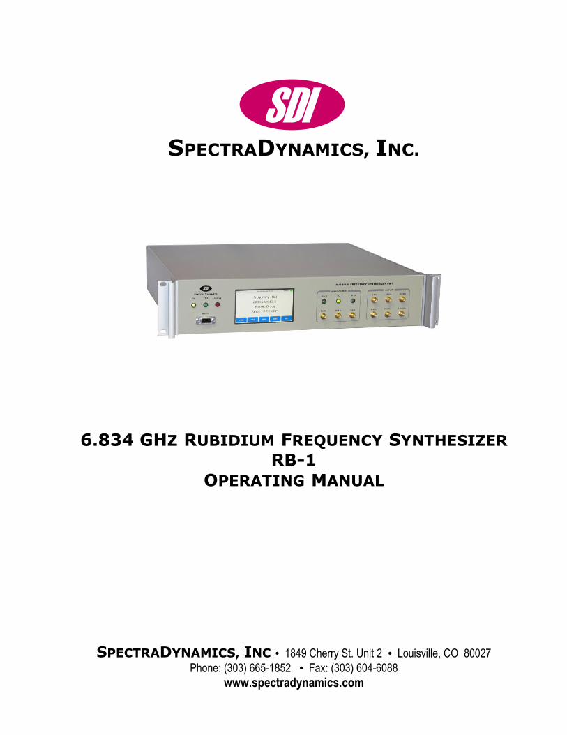
SDI SPECTRADYNAMICS, INC. 6.834 GHZ RUBIDIUM FREQUENCY SYNTHESIZER RB-1 OPERATING MANUAL SPECTRADYNAMICS, INC • 1849 Cherry St. Unit 2 • Louisville, CO 80027 Phone: (303) 665-1852 • Fax: (303) 604-6088 www.spectradynamics.com
Transcript of 1-20 MHz High Isolation Distribution Amplifier · i s pectrad ynamics, i nc. 6.834 ghz rubidium...
SDISPECTRADYNAMICS, INC.
6.834 GHZ RUBIDIUM FREQUENCY SYNTHESIZER RB-1
OPERATING MANUAL
SPECTRADYNAMICS, INC • 1849 Cherry St. Unit 2 • Louisville, CO 80027
Phone: (303) 665-1852 • Fax: (303) 604-6088
www.spectradynamics.com
Copyright © SpectraDynamics, Inc. 2016 1
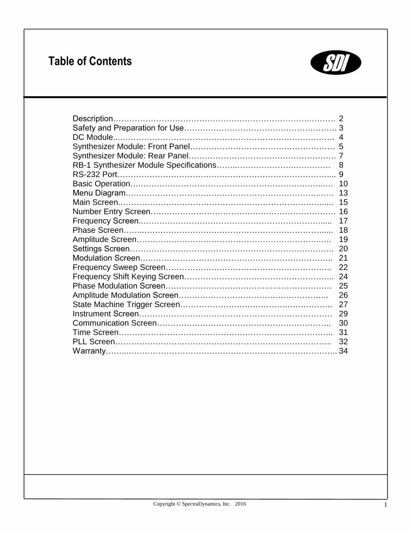
Description……………………………………………………………….………. 2 Safety and Preparation for Use………………………………………………… 3 DC Module...…………………………………………………………………….. 4 Synthesizer Module: Front Panel……………………………………………… 5 Synthesizer Module: Rear Panel………………………………………………. 7 RB-1 Synthesizer Module Specifications……..………………….…………. 8 RS-232 Port…………………………………………………………………….... 9 Basic Operation….…………………………………………………………..…. 10 Menu Diagram….…………………………………………………………..…… 13 Main Screen.…………………………………………………………………..... 15 Number Entry Screen…………………………………………………………… 16 Frequency Screen..…………………………………………………………..... 17 Phase Screen……..…………………………………………………………..... 18 Amplitude Screen…….……………………………………………………..…. 19 Settings Screen…………………………………………………………………. 20 Modulation Screen….………………………………………………………….. 21 Frequency Sweep Screen…………………………………………………….. 22 Frequency Shift Keying Screen……………………………………………….. 24 Phase Modulation Screen…………………………………………………….. 25 Amplitude Modulation Screen……………………………………………….. 26 State Machine Trigger Screen………………………………….…………….. 27 Instrument Screen……………………………………………………………… 29 Communication Screen……………………………………………………….. 30 Time Screen…………………………………………………………………….. 31 PLL Screen…………………….……………………………………………….. 32 Warranty……...………………………………….……………………………….. 34
Table of Contents SDI


Copyright © SpectraDynamics, Inc. 2016 2
The 6.834 GHz Synthesizer RB-1 is made up of two separate units: the Synthesizer Module and the DC Module. The Synthesizer Module is a high stability and high resolution signal source designed to be used in the implementation of a Rubidium atomic clock. The unit is provided in a 2U, 19 inch rack-mount enclosure. All synthesizer functions are accessed from the front panel or a RS232 interface. An external trigger input may be used to synchronize programmable events such as frequency sweeps, phase modulation and amplitude modulation with external events. The synthesizer is implemented with a flexible modular topology. Two ultra-low noise quartz oscillators are part of the multiplication chain from 5 MHz to 100 MHz. Buffered outputs are provided at the front panel for 5 MHz, 10 MHz and 100 MHz. The 100 MHz signal is the highest frequency in the low frequency section of the synthesizer. This 100 MHz signal is distributed using a one input, four output isolation amplifier. One of these 100 MHz signals is used as the reference for a 6.8 GHz DRO. The output of the 6.8 GHz DRO is buffered and used to drive the LO port of a single-sideband mixer. The second 100 MHz signal is used to generate the 200 MHz clock for the DDS synthesizer module. The DDS synthesizer generates a 34.xx MHz signal with 48 bit resolution and modulation capabilities. The DDS synthesizer output drives the IF port of the single-sideband mixer. The upper sideband of the mixer is selected as the output generating the 6.834 GHz output signal. The amplitude of the 6.834 GHz output is controlled with 12 bits of resolution and an internal relay may be used to turn off the RF signal. The DC Module, also in a 2U, 19-inch rack-mount enclosure, provides the DC power to the Synthesizer Module through a DC power cable.
Description SDI
SPECTRADYNAMICS, INC • 1849 Cherry St. Unit 2 • Louisville, CO 80027 • Phone: (303) 665-1852 • Fax: (303) 604-6088
www.spectradynamics.com Se habla español
Copyright © SpectraDynamics, Inc. 2016 3
CAUTION! Voltages capable of causing injury or death are present in this instrument. Use extreme caution whenever the instrument cover is removed.
Line Voltage This DC Module for this instrument can be setup to operate on 110-120 or 220-240
VAC and a line frequency of 50 to 60 Hz. The setup voltage for this DC Module is
specified on page 4. For conversion to a different line voltage please contact SDI.
Fuse A 2.0 Ampere 250V slow-blow fuse is used for 100-120 VAC operation A 1.0 Ampere 250V slow-blow fuse is used for 220-240 VAC operation. Only replace fuses with the same type and specifications.
Line Cord The RB-1 DC Module has a detachable three wire power cord for connection to a grounded power source. The enclosure of the unit is directly connected to the outlet ground to protect against electrical shock. Always use an outlet with a protective ground and do not disable this safety mechanism.
Service Do not attempt to service or adjust the instrument unless another person, capable of providing first aid or resuscitation, is present.
Operation To operate the RB-1 unit, locate the AC power entry connector on the rear panel of the RB-1 DC Module and connect the AC power cable. When power is applied to the RB-1
DC Module, LEDs located on the front panel, labeled “ON”, should light up. Make sure
that the RB-1 Synthesizer Module has the STANDBY switch in OFF position. Using the DC cable provided, connect the DC connector located on the rear panel of the DC Module to the DC connector located on the rear panel of the RB-1 Synthesizer Module. Make sure to locate the DC module away from the synthesizer module. The synthesizer module is sensitive to the mechanical vibration and magnetic fields produced by the DC module. Once all AC and DC cables are connected you can put the STANDBY switch in the ON position.
Safety and Preparation for Use SDI

Copyright © SpectraDynamics, Inc. 2016 4
FRONT PANEL
+12 VD, +/-12V, +15V, +24V The LEDs are on when power is applied to the unit.
REAR PANEL
AC POWER ENTRY MODULE The RB-1 DC Module is configured to operate on:
100-120 VAC
220-240 VAC
DC OUTPUT 1 Connector for the DC power to be supplied to the RB-1 Synthesizer Module
DC OUTPUT 2 Connector for the DC power to be supplied to the CS-1 Synthesizer Module
ENCLOSURE Size: 2U X 19” X 16” Weight: 22 lbs
DC Module SDI
Copyright © SpectraDynamics, Inc. 2016 5
ON The LED is on, when power is applied to unit and the unit is operating properly.
DATA The LED is on when data is being sent or received via the RS-232 port.
STATUS This LED is a hardware representation of the system status flag. The LED is turned on when an error has occurred. The LED will stay ON even if the error condition has been automatically corrected for or is no longer present. The user must go to the PLL Status Menu to clear the status flag with the soft key CLR.
RS-232 DB-9 connector for serial communications. This is a dumb terminal RS-232 port. A null modem adapter is not required.
DISPLAY The LCD display and touch screen is used to control the RB-1 in local control mode.
REFERENCE INPUTS
Signal The Signal LED will turn on when the external reference is present at the Ext Ref port.
PLL The PLL LED will turn on when the RB-1 internal PLLs are operating properly.
Ext Ref SMA input for the 5 MHz external reference signal (+/-0.1 Hz, level +7 to +15 dBm. This input port has an impedance of 50 ohms when an external reference is provided and an impedance of 10 kOhm when routed to the tuning port of the internal 5 MHz crystal. (See Alternative Reference Configurations p.11)
Mod In SMA input for the external modulation signal.
Trig In SMA input for the state machine trigger signal.
RF On The RF On LED will turn on when the 6.834 GHz output signal is activated.
SDI
Synthesizer Module: Front Panel
Copyright © SpectraDynamics, Inc. 2016 6
OUTPUTS
5 MHz SMA output providing a buffered copy of the 5 MHz reference signal. This output signal has a level of +14 dBm ± 1 dB.
10 MHz SMA output providing a buffered copy of the 5 MHz reference signal multiplied by 2. This output signal has a level of +14 dBm ± 1 dB.
100 MHz SMA output providing a buffered copy of the internally generated 100 MHz signal. This output signal has a level of +14 dBm ± 1 dB.
34 MHz SMA output providing a buffered copy of the internal DDS (Direct Digital Synthesizer) output, phase locked to the 100 MHz reference signal. This output signal has a level of -3 dBm ± 1 dB when the front panel amplitude setting is 0 dBm.
6.8 GHz SMA output providing a buffered copy of the internal DRO (Dielectric Resonator Oscillator) output, phase locked to the reference signal. This output signal has a level of -7 dBm ± 1 dB.
6.834 GHz SMA buffered output providing the frequency/phase modulated 6.834 GHz signal, phase locked to the reference signal. This output signal has a level between -10 dBm and +15 dBm and the default value is 0 dBm. An internal relay is used to turn off the RF signal.
SDI
Synthesizer Module: Front Panel
Copyright © SpectraDynamics, Inc. 2016 7
DC INPUT Connector for the DC power provided to the Synthesizer Module by the DC Module.
STANDBY Standby Switch turns off the synthesizer but keeps all oscillators powered on.
SDI
Synthesizer Module: Rear Panel

Copyright © SpectraDynamics, Inc. 2016 8
External Reference 5.0 MHz ± 2.0·10-8 +7 dBm to +15 dBm
Rack-mount Enclosure Size: 2U X 19” X 16” Weight: 20 lbs
PARAMETER CONDITIONS TYP MAX UNITS
Frequency Stability y()
Ref. 5 MHz, +13 dBm
Pair measurement
Averaging time
1 s
10 s
100 s
1000 s
100000 s
1000000 s
1·10-13
1·10-14
1·10-15
2·10-16
2·10-17
2·10-17
-
-
Phase Noise L(f)
Carrier 6.834 GHz
(PLL locked at 0.5Hz BW for measurement)
(5MHz to 6.834GHz Multiplication
Noise at 1 Hz offset is -75dBc/Hz
at the 6.834 GHz output)
Offset frequency
1 Hz
10 Hz
100 Hz
1 kHz
10 kHz
100 kHz
1 MHz
-57
-87
-97
-120
-127
-129
-140
-54
-84
-94
-117
-124
-126
-137
dBc/Hz
Phase Noise L(f)
Carrier 100 MHz
Offset frequency
10 Hz
100 Hz
1 kHz
>10 kHz
-126
-134
-159
-174
-123
-131
-156
-172
dBc/Hz
Phase Noise L(f)
Carrier 10 MHz
Offset frequency
1 Hz
10 Hz
100Hz
>1 kHz
-113
-146
-163
-167
-110
-144
-160
-165
dBc/Hz
Phase Noise L(f)
Carrier 5 MHz
Offset frequency
1 Hz
10 Hz
100Hz
>1 kHz
-120
-150
-167
-175
-117
-147
-165
-173
dBc/Hz
Temperature coefficient @ 6.834 GHz 0.5 ps/K
SDI
RB-1 Synthesizer Module Specifications

Copyright © SpectraDynamics, Inc. 2016 9
RS-232 Communication Port The RB-1 Synthesizer Module functions are accessed through the RS-232 port located on the front panel. A standard serial cable with a DB-9 connector can be used to interface to the unit. The user can input commands using a simple dumb terminal program on a remote computer or more sophisticated control can be used with software such as Labview. On the front panel above the RS-232 connector the LED labeled DATA will light up when data is being received or sent on the RS-232 port and can be used to verify that the unit is communicating.
Port Settings On power-up the RS-232 port settings are: Baud rate 9600 8 Bits 1 Stop Bit No Parity. Hardware handshaking is not used. The DB-9 connector pin-out is described below. Pin Function 1 NC 2 Data out 3 Data in 4 NC 5 GND 6 NC 7 NC 8 NC 9 NC
RS-232 Port SDI

Copyright © SpectraDynamics, Inc. 2016 10
Upon connection of the DC Module to the AC power outlet and the DC connectors on the Rear Panel of both Modules, the Synthesizer Module has the ON LED lit up indicating that RB-1 is turned on. The DATA LED is turned off indicating that the unit is not communicating through the RS-232 port and it is ready to receive commands from the touch screen on the front panel. The STATUS LED is turned ON during the time necessary to warm-up the internal crystal oscillators. The crystal may take up to 2 hours to warm up and up to 24 hours to stabilize.
Reference Configuration Upon power-up, the machine is set to work in its Internal Reference configuration that is using its internal 5 MHz crystal oscillator as the reference signal. In this configuration, the Ext Ref port is connected to the tuning port of the internal low-noise 5 MHz reference crystal, which is now the main reference for the synthesizer. The Ext Ref port is DC coupled and has 10 kOhm impedance. The crystal has a tuning coefficient of 0.3 ± 0.1 Hz/V that allows the steering of the crystal frequency over a frequency range of +/- 2.5 Hz. The PLL LED will be turned on indicating that the 100 MHz oscillator is locked to the internal 5 MHz reference. To set the RB-1 to work in External Reference configuration use the following sequence:
SET INST PLL EXT
then apply a 5 MHz signal with power level between +10 and +15 dBm to the Ext Ref port. Both PLLs will be properly locked as indicated by the illuminated PLL LED.
Press the soft key EXIT three times to return to the Main Menu.
Basic Operation SDI

Copyright © SpectraDynamics, Inc. 2016 11
Output
Upon power up, the internal relay at the 6.834 GHz output port is in the OFF position and the RF ON LED is turned off.
To turn the RF output on, press the softkey RFON in the Main Menu. When the RF is turned on, the signal level at the 6.834 GHz port is 0 dBm with a preset frequency of 6.834 682 610 904 29 GHz. The 6.8 GHz port has a signal with level -7 dBm. The 34 MHz port has a signal with preset frequency 34.682 610 904 29 MHz and level –0 dBm.
Menu: MAIN
Frequency Control The carrier frequency of the 6.834 GHz output signal is controllable using the touch screen on the front panel or through the RS-232 Communication Port. The frequency can range from 6.810 GHz to 6.860 GHz with a resolution is 10-6 Hz.
Menu: FREQ
Amplitude control The signal amplitude at the 6.834 GHz port is controllable through the RS-232 Communication Port or using the touch screen on the front panel. The amplitude can range from -10 dBm to +15 dBm with a resolution of about 0.1 dB.
Menu: AMPL
Signal Modulation
Four types of signal modulation are available to the user. The first one is linear Frequency Modulation (FM) and allows to sweep the RF carrier frequency between two values (Start and Stop) chosen by the user. The second one is Frequency Shift Keying (FSK) Modulation and allows sideline interrogation of the Rubidium resonance. The modulation is obtained by alternating between two frequency values (F1 and F2) for the 6.834 GHz output signal. The two frequency values can range from 6.810 GHz to 6.860 GHz with a resolution of 10-6 Hz.
Basic Operation SDI
Copyright © SpectraDynamics, Inc. 2016 12
The third possibility is Phase Shift Keying (PSK) Modulation obtained by alternately adding two specified amounts of phase (PHAS1 and PHAS2) to the 6.834 GHz output signal. The phase amounts can range between 0 and 360 degrees with resolution 360/4096 degrees. The last modulation type is Amplitude Shift Keying Modulation (ASK), obtained by turning on and off the amplitude of the 6.834 GHz output signal. The time used by the
RF signal to go from on to off (and vice versa) can range from 81.910-6 s to 5242.810-6 s. The modulation parameters can be programmed through the RS-232 or entered using the front panel touch screen.
Menu: MOD The Trigger Menu offers the possibility of synchronizing the modulation events with an external trigger provided at the Trigger In Port, setting the RB-1 to operate as a state machine. The operation as a state machine includes up to 10 states, each one incremented on every rising edge of the hardware trigger. When the state number 10 is reached the next hardware trigger resets the machine to state 1 and the cycle can continue indefinitely. The number of states or events in a sequence is programmed to be 1 through 10. Each state is defined by four parameters: frequency, phase, amplitude of the 6.834 GHz signal and the state of the RF relay (on or off). Note: it is not recommended to switch the RF relay with every trigger event because will significantly limit the RF relay lifetime, which is specified by a finite number of switching cycles. MTBF typically 5 million cycles.
Menu: TRIG The Trigger Menu and the Modulation Menu are mutually exclusive: when the modulation parameters are entered using one of them, then the other is automatically ignored.
Basic Operation SDI

Copyright © SpectraDynamics, Inc. 2016 13
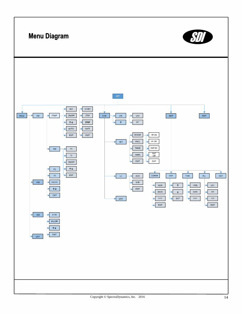
*This Softkey gives access to the Number Menu (NUM) to make numeric entries.
Menu Diagram SDI
Copyright © SpectraDynamics, Inc. 2016 14
Menu Diagram SDI
Menu Diagram SDI
Copyright © SpectraDynamics, Inc. 2016 15
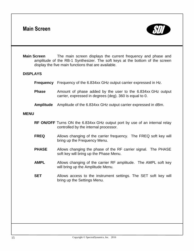
Main Screen The main screen displays the current frequency and phase and amplitude of the RB-1 Synthesizer. The soft keys at the bottom of the screen display the five main functions that are available.
DISPLAYS
Frequency Frequency of the 6.834xx GHz output carrier expressed in Hz.
Phase Amount of phase added by the user to the 6.834xx GHz output carrier, expressed in degrees (deg). 360 is equal to 0.
Amplitude Amplitude of the 6.834xx GHz output carrier expressed in dBm.
MENU
RF ON/OFF Turns ON the 6.834xx GHz output port by use of an internal relay controlled by the internal processor.
FREQ Allows changing of the carrier frequency. The FREQ soft key will bring up the Frequency Menu.
PHASE Allows changing the phase of the RF carrier signal. The PHASE soft key will bring up the Phase Menu.
AMPL Allows changing of the carrier RF amplitude. The AMPL soft key will bring up the Amplitude Menu.
SET Allows access to the instrument settings. The SET soft key will bring up the Settings Menu.
SDI
Main Screen

Copyright © SpectraDynamics, Inc. 2016 16
Number Screen The number entry screen is used to make numeric entries.
DISPLAYS
The current setting will be displayed across the top of the screen. The new entry is displayed in a number entry box.
SPECIAL KEYS
Hz Enter number in Hertz.
kHz Enter number in kiloHertz.
MHz Enter number in MegaHertz.
deg Enter number in degrees.
dBm Enter number in dBm.
Vrms Enter number in Volts RMS.
Vpp Enter number in Volts peak-to-peak.
BK Backspace.
ENTER Enter new number and exit number menu.
ESC Exit number menu discarding changes.
0-9 Numbers zero through nine.
. Decimal point.
- Negative sign.
SDI
Number Entry Screen
Copyright © SpectraDynamics, Inc. 2016 17
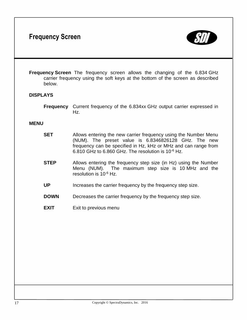
Frequency Screen The frequency screen allows the changing of the 6.834 GHz carrier frequency using the soft keys at the bottom of the screen as described below.
DISPLAYS
Frequency Current frequency of the 6.834xx GHz output carrier expressed in Hz.
MENU
SET Allows entering the new carrier frequency using the Number Menu (NUM). The preset value is 6.8346826128 GHz. The new frequency can be specified in Hz, kHz or MHz and can range from 6.810 GHz to 6.860 GHz. The resolution is 10-6 Hz.
STEP Allows entering the frequency step size (in Hz) using the Number Menu (NUM). The maximum step size is 10 MHz and the resolution is 10-6 Hz.
UP Increases the carrier frequency by the frequency step size.
DOWN Decreases the carrier frequency by the frequency step size.
EXIT Exit to previous menu
Frequency Screen SDI

Copyright © SpectraDynamics, Inc. 2016 18
Phase Screen The phase screen allows the changing of the 6.834 GHz carrier phase using the soft keys at the bottom of the screen as described below.
DISPLAYS
Phase Current phase added to the 6.834xx GHz output carrier, expressed in degrees (deg).
MENU
SET Allows entering the phase to be added to the 6.834xx GHz signal using the Phase Entry Menu. The new phase is specified in degrees (deg) and must be with the interval -360 deg to 360 deg. The phase resolution is 0.022 deg.
STEP Allows entering the phase step size (in degrees) using the Phase Entry Menu. The maximum step size is 360 deg. The phase step resolution is 0.022 deg.
UP Increases the carrier phase by the phase step size.
DOWN Decreases the carrier phase by the phase step size.
EXIT Exit to previous menu
Phase Screen SDI
Copyright © SpectraDynamics, Inc. 2016 19
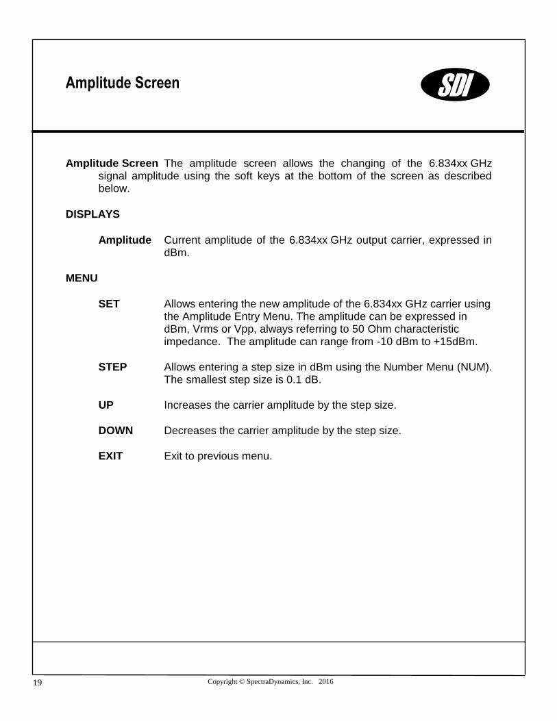
Amplitude Screen The amplitude screen allows the changing of the 6.834xx GHz signal amplitude using the soft keys at the bottom of the screen as described below.
DISPLAYS
Amplitude Current amplitude of the 6.834xx GHz output carrier, expressed in dBm.
MENU
SET Allows entering the new amplitude of the 6.834xx GHz carrier using the Amplitude Entry Menu. The amplitude can be expressed in dBm, Vrms or Vpp, always referring to 50 Ohm characteristic impedance. The amplitude can range from -10 dBm to +15dBm.
STEP Allows entering a step size in dBm using the Number Menu (NUM). The smallest step size is 0.1 dB.
UP Increases the carrier amplitude by the step size.
DOWN Decreases the carrier amplitude by the step size.
EXIT Exit to previous menu.
Amplitude Screen SDI

Copyright © SpectraDynamics, Inc. 2016 20
Settings Screen The settings screen is used to access, view and edit instrument options.
MENU
MOD Setup Modulation options.
FM Setup Frequency Modulation.
PM Setup Phase Modulation.
AM Setup Amplitude Modulation.
STM State Machine Trigger setup and information. The STM key will bring up the State Machine Trigger Screen.
INST Instrument setup and information. The INST key will bring up the Instrument Screen.
EXIT Exit to previous screen.
Settings Screen SDI
Copyright © SpectraDynamics, Inc. 2016 21
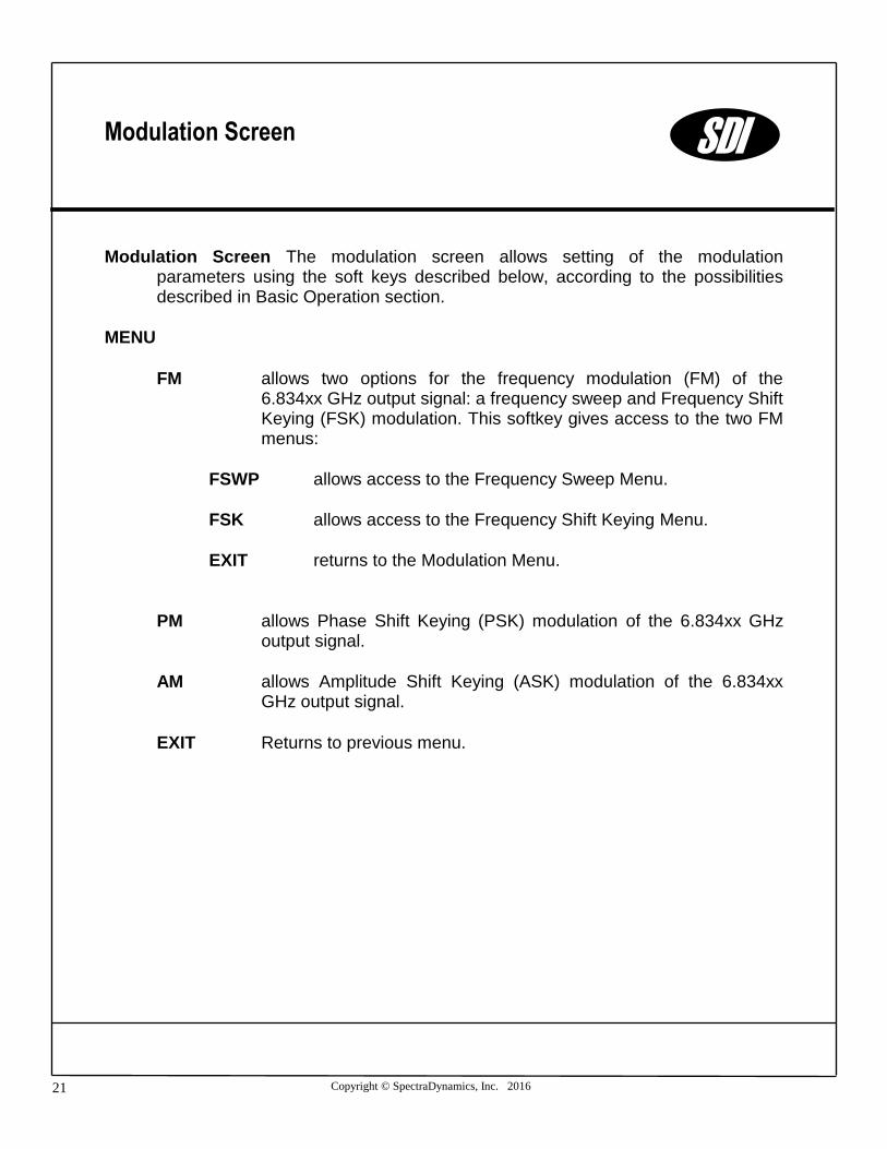
Modulation Screen The modulation screen allows setting of the modulation parameters using the soft keys described below, according to the possibilities described in Basic Operation section.
MENU
FM allows two options for the frequency modulation (FM) of the 6.834xx GHz output signal: a frequency sweep and Frequency Shift Keying (FSK) modulation. This softkey gives access to the two FM menus:
FSWP allows access to the Frequency Sweep Menu.
FSK allows access to the Frequency Shift Keying Menu.
EXIT returns to the Modulation Menu.
PM allows Phase Shift Keying (PSK) modulation of the 6.834xx GHz output signal.
AM allows Amplitude Shift Keying (ASK) modulation of the 6.834xx GHz output signal.
EXIT Returns to previous menu.
Modulation Screen SDI
Copyright © SpectraDynamics, Inc. 2016 22
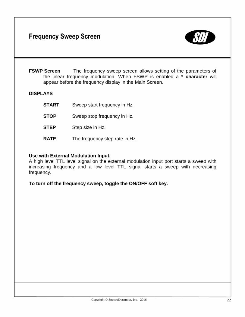
FSWP Screen The frequency sweep screen allows setting of the parameters of
the linear frequency modulation. When FSWP is enabled a * character will appear before the frequency display in the Main Screen.
DISPLAYS
START Sweep start frequency in Hz.
STOP Sweep stop frequency in Hz.
STEP Step size in Hz.
RATE The frequency step rate in Hz.
Use with External Modulation Input. A high level TTL level signal on the external modulation input port starts a sweep with increasing frequency and a low level TTL signal starts a sweep with decreasing frequency.
To turn off the frequency sweep, toggle the ON/OFF soft key.
SDI
Frequency Sweep Screen

Copyright © SpectraDynamics, Inc. 2016 23
MENU
SET Allows entering the frequency sweep parameters. Each one of the soft keys described below will bring up the Frequency Entry Menu, to enter the numeric quantities, expressing them in Hz, kHz or MHz.
START Sweep start frequency in Hz. Valid range of values is from
6.810 GHz to 6.860 GHz. The resolution is 10-6 Hz.
STOP Sweep stop frequency in Hz. Valid range of values is from
6.810 GHz to 6.860 GHz. The resolution is 10-6 Hz.
STEP Step size in Hz. The step size must be smaller than the difference in frequency between the start and stop frequency. The smallest step size is 10-6 Hz.
RATE The frequency step rate in Hz. The frequency step rate must be between 95.4 Hz and 50 MHz.
EXIT Returns to the previous menu.
ON/OFF Toggles frequency sweep on or off.
UP/DOWN Toggles between sweep upward or downward in frequency.
AUTO Turn on automatic sweep function allowing for continuous upward/downward sweep.
EXIT Exit to previous menu.
SDI
Frequency Sweep Screen

Copyright © SpectraDynamics, Inc. 2016 24
FSK Screen The frequency shift keying screen is used to access, view and edit
frequency shift keying modulation options. When FSK is enabled a * character will appear before the frequency display in the Main Screen.
DISPLAYS
F1 First frequency setting in Hz.
F2 Second frequency setting in Hz.
MENU
F1 Allows entering the first frequency value using the NUM menu. The valid range for it is from 6.810 GHz to 6.860 GHz. The resolution is
10-6 Hz.
F2 Allows entering the second frequency value using the Frequency Entry Menu. F2 needs to be larger than F1 and within the range specified above.
ON/OFF Toggles FSK modulation of or off.
UP/DOWN Toggle between frequency 1 and frequency 2.
EXIT Exit to previous menu.
Use with External Modulation Input. A low level TTL level signal on the external modulation input port will select F1 to be the output and a high level TTL signal will select F2 to be the output.
To turn off the modulation, toggle the ON/OFF soft key.
SDI
Frequency Shift Keying Screen

Copyright © SpectraDynamics, Inc. 2016 25
PM Screen The phase modulation screen is used to access, view and edit
phase shift keying modulation options. When PM is enabled a * character will appear before the phase display in the Main Screen.
DISPLAYS
Phase 1 First phase setting in degrees.
Phase 2 Second phase setting in degrees.
MENU
PHAS1 Allows entering the first phase value using the Phase Entry Menu. The phase is specified in degrees (deg) and must be within the interval -360 deg to 360 deg. The resolution is 0.022 deg.
PHAS2 Allows entering the second phase value using the Phase Entry Menu according to the specifications above.
ON/OFF Toggle phase modulation on or off.
UP/DOWN Toggle between phase 1 and phase 2.
EXIT Exit to previous menu.
Use with External Modulation Input. The phase of the output signal is set to phase 1 when a low level TTL signal is applied to the external modulation input port. The phase of the output signal is set to phase 2 when a high level TTL signal is applied to the external modulation input port.
To turn off the modulation, toggle the ON/OFF soft key.
SDI
Phase Modulation Screen
Copyright © SpectraDynamics, Inc. 2016 26
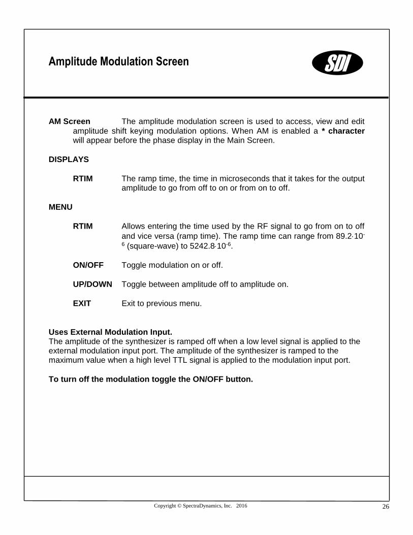
AM Screen The amplitude modulation screen is used to access, view and edit
amplitude shift keying modulation options. When AM is enabled a * character will appear before the phase display in the Main Screen.
DISPLAYS
RTIM The ramp time, the time in microseconds that it takes for the output amplitude to go from off to on or from on to off.
MENU
RTIM Allows entering the time used by the RF signal to go from on to off
and vice versa (ramp time). The ramp time can range from 89.210-
6 (square-wave) to 5242.810-6.
ON/OFF Toggle modulation on or off.
UP/DOWN Toggle between amplitude off to amplitude on.
EXIT Exit to previous menu.
Uses External Modulation Input. The amplitude of the synthesizer is ramped off when a low level signal is applied to the external modulation input port. The amplitude of the synthesizer is ramped to the maximum value when a high level TTL signal is applied to the modulation input port.
To turn off the modulation toggle the ON/OFF button.
SDI
Amplitude Modulation Screen

Copyright © SpectraDynamics, Inc. 2016 27
SMT Screen The Trigger Menu allows synchronization of the modulation events with an externally provided hardware trigger (see Synthesizer Module Font Panel), setting the RB-1 to operate as a state machine. The operation as a state machine includes up to 9 states, each one incremented on every rising edge of the hardware trigger. When the state number 9 is reached the next hardware trigger resets the machine to state 1 and the cycle can continue indefinitely. The number of states or events in a sequence is programmed to be 1 through 9. Each state is identified by four parameters: frequency, phase and amplitude of the RF carrier and the state of the RF relay (on or off).
Note: it is not recommended to switch the RF relay with every trigger event because will
significantly limit the RF relay lifetime, which is specified by a finite number of switching cycles. MTBF is typically 5 million cycles.
DISPLAYS
State n/m Indicates which state is being edited (n) and the total number of states that have been programmed (m).
RF ON/OFF Current position of the RF relay at the 6.834xx GHz output port.
SWP ON/OFF Current frequency sweep setting.
Frequency Current frequency (Hz) of the 6.8346xx GHz output carrier.
Phase Current phase (degrees) of the 6.8346xx GHz output carrier.
Amplitude Current amplitude (dBm) of the 6.8346xx GHz output carrier.
MENU
ON Enables, disables and resets the operation of RB-1 as a state machine
OFF Disables the state machine operation.
RST Resets the state machine cycle, forcing the next executable state to be state 1.
SDI
State Machine Trigger Screen
Copyright © SpectraDynamics, Inc. 2016 28
NEXT Allows access to the next state of the state machine.
SET Allows the setting of the four parameters describing each state of the RB-1.
RF/SWP Sets the RF relay to be on or off for this state and allows enabling or disabling of frequency sweeps.
FREQ Allows entering the carrier frequency for this state, using the Number Menu (NUM). The frequency can be specified in Hz, kHz or MHz and can range from 6.810 GHz to 6.860 GHz. The resolution is 10-6 Hz.
PHAS Allows entering the phase to be added to the RF carrier signal for this state, using the Phase Entry Menu. The phase is specified in degrees (deg) and must be with the interval -360 deg to 360 deg. The resolution is 0.022 deg.
AMPL Allows entering the amplitude of the RF carrier for this state, using the Amplitude Entry Menu. The amplitude can be expressed in dBm, Vrms or Vpp, always referring to 50 Ohm characteristic impedance. The amplitude can range from -10 dBm to +15 dBm.
EXIT Enters the new state.
+/- Allows adding (subtract) a state to (from) the programmed
sequence:
ADD Adds a new state, always at the end of the existing sequence. By default the new state is a copy of the last state of the sequence before the addition.
DEL Eliminates the last state of the sequence.
EXIT Return to previous menu.
SDI
State Machine Trigger Screen

Copyright © SpectraDynamics, Inc. 2016 29
Instrument Screen The instrument screen is used to view or change instrument configuration settings.
MENU
COMM Set serial communications options and RS-232 remote control configuration.
DISP Change the brightness of the LCD display.
UP Increase the value.
DOWN Decrease the value.
EXIT Exit to previous screen.
TIME Set the instrument date and time.
PLL Allows access to the PLL Menu to change the reference configuration of RB-1.
EXIT Exit to previous menu.
Instrument Screen SDI
Copyright © SpectraDynamics, Inc. 2016 30
Communications Screen The communications screen displays the current RS-232 serial port settings. The soft keys at the bottom of the screen are used to set new RS-232 settings, initiate RS-232 control of the instrument or test the serial port connection. The RS-232 port is setup to be controlled by a dumb terminal. A null modem adapter is not needed and should not be used. Hardware handshaking is not used. For additional pin-out information please refer to the RS-232 port section on page 9 of this manual.
DISPLAYS
Current baud rate setting.
MENU
REM/LOCL Allows entering remote control mode: RB-1 is now waiting for commands through the RS-232 serial port. The RS-232 port is set as a dumb terminal. A null modem adapter is not needed and should not be used. Hardware handshaking is not used. For additional pin-out information please refer to the RS-232 Port Communication section of the manual. To restore local control and terminate remote control session use the soft key LOCAL.
BAUD Toggle through available baud rates.
9600, 19200, 38400, 57600, 115200, 14400, 28800
TEST Test Serial port.
EXIT Exit to previous screen.
Communication Screen SDI
Copyright © SpectraDynamics, Inc. 2016 31
Time Screen The time screen allows changing time and date of RB-1, according to the soft keys described below.
DISPLAYS
Time current time in the form hh:mm:ss.
Date current date in the form mm/dd/yy.
MENU
TIME Allows entering new time using the Time Entry Menu in the form hh:mm:ss.
DATE Allows entering new time using the Date Entry Menu in the form mm/dd/yy.
UP Increments the current time by one second.
DOWN Decrements the current time by one second.
EXIT Return to previous menu.
Time Screen SDI
Copyright © SpectraDynamics, Inc. 2016 32
PLL Screen
The PLL Menu is used to choose the Reference Configuration and to view the current PLL voltages and RF power levels. All voltages and levels that are in the normal operating range will be displayed in green. All voltages and levels that are outside the normal operating range and indicate an error condition will be displayed in red. The CLR soft key can be used to clear the status register and turn off the status LED.
Note: The CLR function will turn off the status LED only if the error condition has been resolved.
DISPLAYS
5 MHz: power level of the internal 5 MHz signal. It should be about +12 dBm.
Ref power level of the 5 MHz external reference signal. It should be between +7 and +15 dBm.
100 MHz: power level of the 100 MHz signal. It should be at least +11 dBm.
LVn: indicates the locking voltage for the three PLLs of the RB-1. n=1 is the 5 MHz PLL, while n=2 is the 100 MHz PLL. They are locked when the displayed value is between 0.2 and 0.3. n=3 is the PLL for the DRO and it is locked when the displayed value is 2.5.
TVn: indicates the tuning voltage for the internal 5 MHz and 100 MHz oscillators. It should be within ±5.
DC tuning enabled indicates that the Internal Reference configuration is enabled. This is displayed in place of Ref, LV1 and TV1 because the 5 MHz PLL is disabled.
PLL Screen SDI
Copyright © SpectraDynamics, Inc. 2016 33
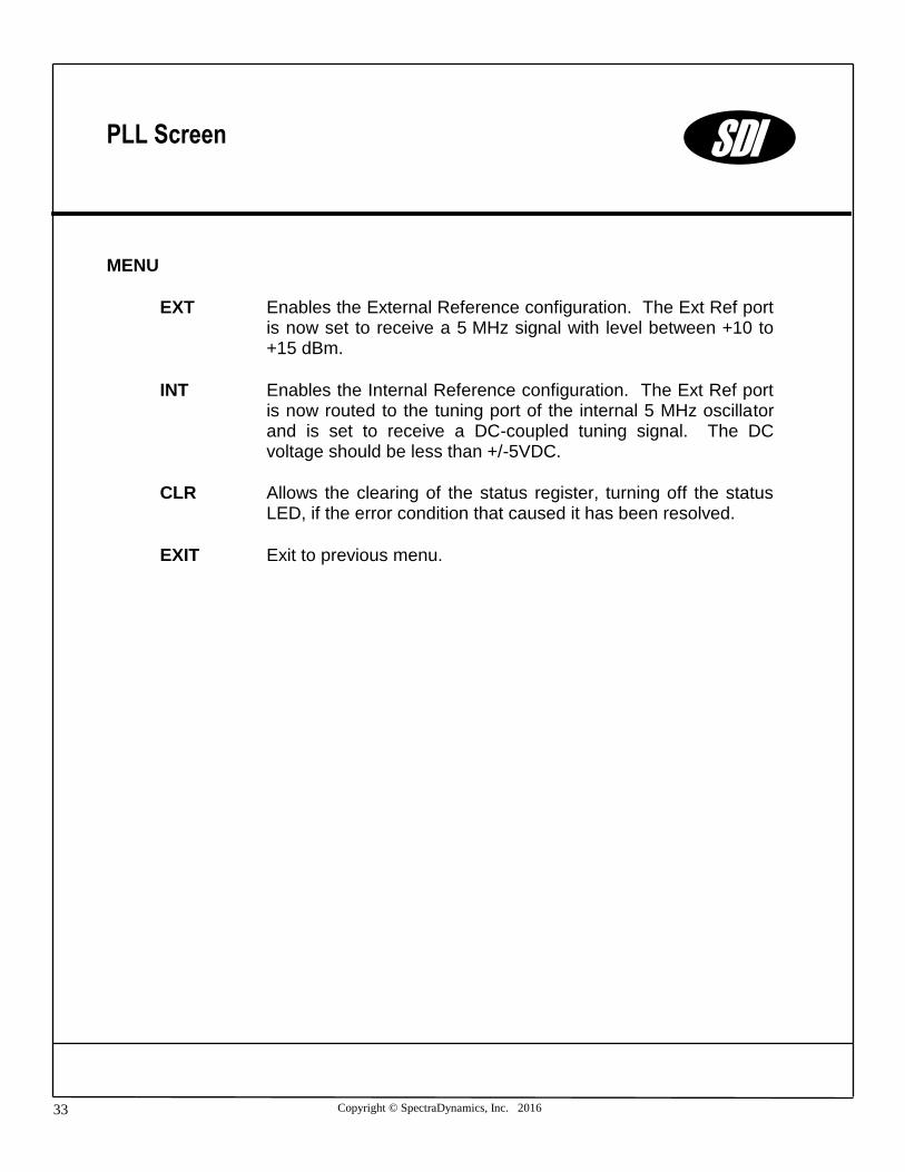
MENU
EXT Enables the External Reference configuration. The Ext Ref port is now set to receive a 5 MHz signal with level between +10 to +15 dBm.
INT Enables the Internal Reference configuration. The Ext Ref port is now routed to the tuning port of the internal 5 MHz oscillator and is set to receive a DC-coupled tuning signal. The DC voltage should be less than +/-5VDC.
CLR Allows the clearing of the status register, turning off the status LED, if the error condition that caused it has been resolved.
EXIT Exit to previous menu.
PLL Screen SDI

Copyright © SpectraDynamics, Inc. 2016 34
The RB-1 is warranted to be free of defects under normal operating conditions, as specified, for one year from date of original shipment from SpectraDynamics, Inc (SDI). SDI’s obligation and liability under this warranty is expressly limited to repairing or replacing, at SDI’s option, any product not meeting the said specifications. This warranty shall be in effect for one (1) year from the date a RB-1 is sold by SDI. SDI makes no other warranty, express or implied, and makes no warranty of the fitness for any particular purpose. SDI’s obligation under this warranty shall not include any transportation charges or costs of installation or any liability for direct, indirect, or consequential damages or delay. Any improper use, operation beyond capacity, substitution of parts not approved by SDI, or any alteration or repair by others in such manner as in SDI’s reasonable judgment affects the product materially and adversely shall void this warranty. No employee or representative of SDI is authorized to change this warranty in any way or grant any other warranty.
Warranty SDI
SPECTRADYNAMICS, INC • 1849 Cherry St. Unit 2 • Louisville, CO 80027 • Phone: (303) 665-1852 • Fax: (303) 604-6088
www.spectradynamics.com

RB-1/R03