- 1 - - 1 -1 N E W S News... · 3 Dry Pipe 2 model – outstanding capability of PIPENET Transient...
19
- 1 - AUTUMN 2019 PIPENET VISION ® 1.10.0 RELEASE Welcome to PIPENET VISION 1.10.0! We are pleased to deliver some fabulous enhancements across all modules to save time and make the PIPENET experience even better. IN THIS EDITION YOU WILL FIND: Page 2 – PIPENET VISION 1.10.0: brief overview of the latest release Page 3 – Dry Pipe 2 model: new outstanding capability of Transient Module for modelling air volume in pipes Page 8 – Scenario manager: purposes and user guide Page 17 – New Chinese Standard (GB) in Spray/Sprinkler Module Page 18 – Non-Newtonian fluids in Standard Module Page 19 – New flowrate unit: litres per second PIPENET Training Materials Did you know that you can easily master PIPENET by following the examples in our excellent Training Manuals? Training Manuals for all modules are inbuilt in PIPENET. They provide detailed step-by- step guidance and have plenty of practical examples. Data files for all examples are also provided. You can find all the training materials at: PIPENET > Help > Learning > Training Materials PIPENET at OTC and Gastech: thank you to everyone who visited us in Houston PIPENET was a great success again at leading trade shows in Houston this year. We were happy to meet our customers and all other visitors at OTC-2019 in May and at Gastech-2019 in September. Our booth visitors had a great opportunity to see a live demonstration of PIPENET, ask questions and receive answers. Thank you to everyone who visited our booths. We will be happy to meet you again next year! [email protected] P I P E N E T ® N E W S PIPENET Vision 1.10.0 will soon be sent to all customers with active PIPENET Maintenance, Updates and Support and/or active 5-year and 1-year licences. Please contact us if you do not receive it by the middle of December. If you are not a current customer and you would like a copy of PIPENET VISION 1.10.0, please contact us at [email protected]
Transcript of - 1 - - 1 -1 N E W S News... · 3 Dry Pipe 2 model – outstanding capability of PIPENET Transient...

- 1 - - 1 -1
1
AUTUMN 2019
PIPENET VISION® 1.10.0
RELEASE
Welcome to PIPENET VISION 1.10.0! We are pleased to deliver some fabulous enhancements across all modules to save time and make the PIPENET experience even better. IN THIS EDITION YOU WILL FIND: Page 2 – PIPENET VISION 1.10.0: brief overview of the latest release Page 3 – Dry Pipe 2 model: new outstanding capability of Transient Module for modelling air volume in pipes Page 8 – Scenario manager: purposes and user guide Page 17 – New Chinese Standard (GB) in Spray/Sprinkler Module Page 18 – Non-Newtonian fluids in Standard Module Page 19 – New flowrate unit: litres per second
PIPENET Training Materials Did you know that you can easily master PIPENET
by following the examples in our excellent Training
Manuals? Training Manuals for all modules are
inbuilt in PIPENET. They provide detailed step-by-
step guidance and have plenty of practical examples.
Data files for all examples are also provided.
You can find all the training materials at:
PIPENET > Help > Learning > Training Materials
PIPENET at OTC and Gastech: thank you to everyone who visited us in Houston PIPENET was a great success again at leading trade
shows in Houston this year. We were happy to meet
our customers and all other visitors
at OTC-2019 in May and at
Gastech-2019 in September.
Our booth visitors had a great
opportunity to see a live
demonstration of PIPENET,
ask questions and receive
answers. Thank you to
everyone who visited our
booths. We will be happy to
meet you again
next year!
P I P E N E T®
N E W S
PIPENET Vision 1.10.0 will soon be sent to all customers with active PIPENET Maintenance, Updates and Support and/or active 5-year and 1-year licences. Please contact us if you do not receive it by the middle of December. If you are not a current customer and you would like a copy of PIPENET VISION 1.10.0, please contact us at [email protected]

2
PIPENET VISION® 1.10.0 Release
Welcome to PIPENET VISION 1.10.0!
We are pleased to deliver some fabulous enhancements across all modules to save time and make the
PIPENET experience even better.
PIPENET Vision 1.10.0 Transient Module
• Dry Pipe 2 including calculation of air pressure
• New air valve component
• The Scenario Manager facilitates easy comparison of a range of scenarios on one screen.
• Improved searching in Forces dialog.
• Improvements to the graph viewer.
• RES2CSV utility now includes option to export to Excel.
PIPENET Vision 1.10.0 Spray/Sprinkler Module
• Improved formatting of the NFPA report.
• Updated Chinese Standard.
PIPENET Vision 1.10.0 Standard Module
• Non-Newtonian power-law fluids can now be modelled in the Standard Module.
PIPENET All Modules
• Measure and calculate using ‘litres per second’.
• Improved output formatting.
• Module name displayed in title bar.

3
Dry Pipe 2 model – outstanding capability of PIPENET Transient Module for modelling air volume in pipes
One of the powerful, new developments introduced in PIPENET Vision 1.10.0 is the ‘Dry Pipe 2’ Model in PIPENET Transient Module. Dry Pipe 2 Model allows air to flow into the system and considers the effect of air volume in pipes. Dry Pipe 2 Model can simulate complex pipe networks, including:
• dry pipes
• wet pipes and
• components other than pipes.
Q: What is the purpose of the Dry Pipe Model? 1. Improve modelling accuracy by considering the effect of air volume in pipes.
2. Estimate the priming time of dry deluge systems.
3. Evaluate the pressure surge during the priming of a dry system.
Q: What are the differences between Dry Pipe 1 Model and Dry Pipe 2 Model? 1. Dry Pipe 1 Model assumes air pressure is constant 0 barg while Dry Pipe 2 Model calculates
air pressure based on the ideal gas law PV = nRT under isothermal conditions.
2. Dry Pipe 2 Model considers the friction loss of air flow in components (e.g. valve, nozzle etc.)
while Dry Pipe 1 Model ignores it.
3. Dry Pipe 1 Model is usually faster than Dry Pipe 2 Model. Both the models can give accurate
results if air pressure is around 0 barg. Otherwise, Dry Pipe 2 Model provides a better
accuracy.
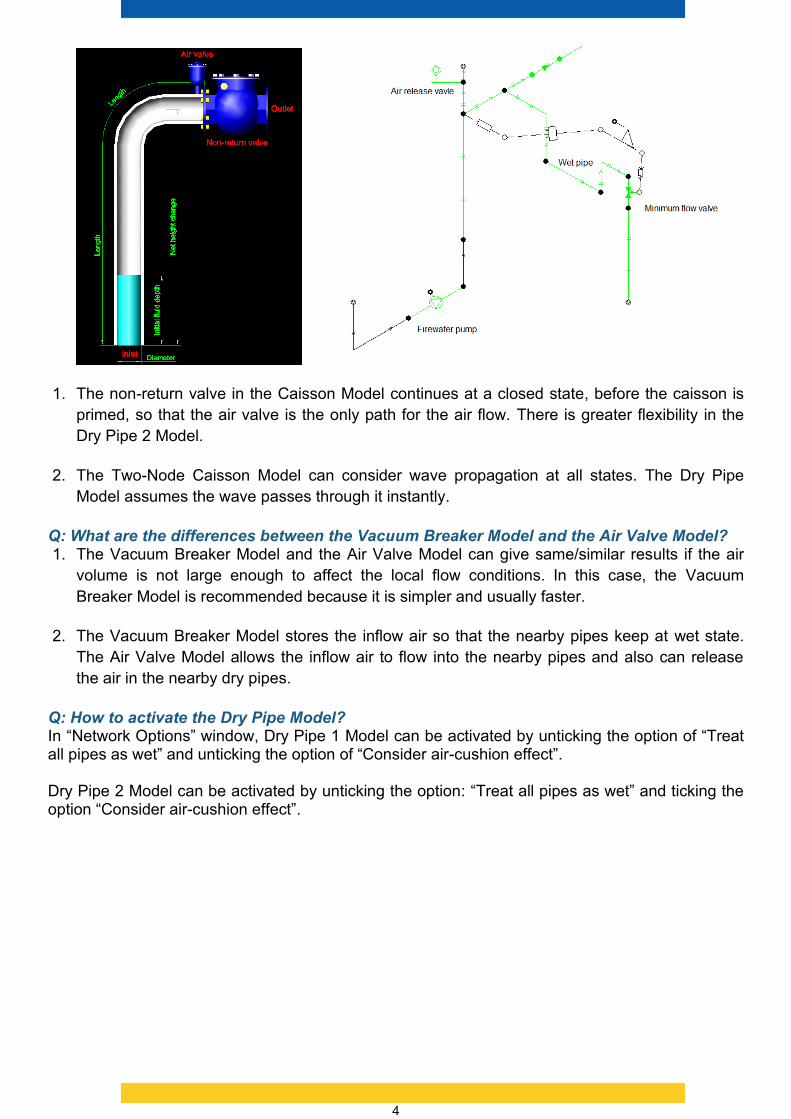
Q: What are the differences between the Caisson Models and Dry Pipe 2 Model? The caisson Models are composed of three components:
• a dry or partially filled pipe,
• a non-return valve and
• an air valve,
and their location is fixed, see the figure below on the left. Dry Pipe 2 model is more flexible, which allows to build a more complex dry network, see the figure below on the right.
4
1. The non-return valve in the Caisson Model continues at a closed state, before the caisson is
primed, so that the air valve is the only path for the air flow. There is greater flexibility in the
Dry Pipe 2 Model.
2. The Two-Node Caisson Model can consider wave propagation at all states. The Dry Pipe
Model assumes the wave passes through it instantly.
Q: What are the differences between the Vacuum Breaker Model and the Air Valve Model? 1. The Vacuum Breaker Model and the Air Valve Model can give same/similar results if the air
volume is not large enough to affect the local flow conditions. In this case, the Vacuum
Breaker Model is recommended because it is simpler and usually faster.
2. The Vacuum Breaker Model stores the inflow air so that the nearby pipes keep at wet state.
The Air Valve Model allows the inflow air to flow into the nearby pipes and also can release
the air in the nearby dry pipes.
Q: How to activate the Dry Pipe Model? In “Network Options” window, Dry Pipe 1 Model can be activated by unticking the option of “Treat all pipes as wet” and unticking the option of “Consider air-cushion effect”. Dry Pipe 2 Model can be activated by unticking the option: “Treat all pipes as wet” and ticking the option “Consider air-cushion effect”.

5
Q: What are the typical applications of the Dry Pipe 2 Model? 1. Dry Pipe 2 Model can simulate complex dry networks. For example, the PIPENET Model on
the right below can simulate the firewater system on the left accurately. The dead end is
modelled by a zero-flow specification.

6
2. Dry Pipe 2 Model can improve calculation accuracy and simplify simulation Model. The model
below is a typical example to calculate the priming time and pressure surge in a dry deluge
system.
3. Dry Pipe 2 Model allows air to flow into the system and considers the effect of air volume on
the system static head. In the cooling water system below, the Dry Pipe Model can predict the
pump trip/reverse speed accurately.

7
Q: What are the limitations of the Dry Pipe Model? 1. The friction loss of air flow is negligible in the pipe model.
2. One pipe only has one air bubble/slug. If both the inlet and outlet of a pipe are dry, the whole
pipe is at dry state.
3. Dry state cannot coexist with channel cavitation state in a single pipe.
4. In Dry Pipe 1 Model, it is assumed that the air pressure is constant 0 barg, i.e. the pressure
loss of air flow is ignored. In addition, there is no obstacle to block air flow to atmospheric exit.
Items such as wet pipe, short pipe, caisson, simple tank, accumulator and closed valves can
create a restriction and increase the pressure above 0 barg.
5. In Dry Pipe 2 Model, the air pressure need not be 0 barg as long as air properties can be
calculated based on the ideal gas law, under isothermal conditions. The pressure loss in
components considers both subsonic and sonic states. In addition, air flow will convert to the
same volume liquid flow in the following cases: (a) the air-liquid mixture is not stratified flow;
(b) air flow into short pipe, pipe bundle, caissons, simple tank and accumulator.

8
Scenario Manager: Purposes and User Guide
Purpose of the Scenario Manager
The scenario manager is intended to make it easy to create variations on a network design and
compare the relative performance of those variants. This can be useful for optimising networks, for
example.
Without the scenario manager, the user themselves must
• Make multiple copies of the network.
• Modify each copy, by hand, to reflect the changes that they want to try.
• Run PIPENET® Vision on each modified file in turn to generate the results.
• Compare the results. For example, for a transient network the user would need to open the
graph viewer and open each .res file.
The scenario manager allows the user to do these steps much more easily.
In the first version of the scenario manager, the user will be limited to modifying Specifications.
However, subsequent versions will support further modifications.
Preparation for Use
The overall process for using the scenario manager to create a new scenario-set is as follows:
1. Create the master model (the network on which the scenarios will be based).
2. Identify the Specification(s) that will be changed in the scenario (via the node to which they
apply).

9
3. Start the scenario manager.
4. Select the master model to use as the basis for the new scenario-set.
5. The scenario manager presents the master model as a read-only scenario (for
comparison).

10
6. Click the blue “Add scenario” button and modify the scenario name and specification(s) in
the new scenario as required.
7. Repeat 6. until all of the scenarios that are needed have been defined.

11
8. Save the scenario set, to remember the scenarios defined and the values changed.
9. Click the Generate button on the ribbon. As the help says, this will make a copy of your
master model for each scenario and automatically edit the copy to apply the specification
changes that you have set.
10. Click the run button to automatically run PIPENET® Vision on each of the scenario models.

12
11. Click the View results button to compare the results of the scenarios.
For a transient model, click the “Compare results in graph viewer…” button. This will start the
graph viewer with the graphical result (.res) file for each scenario already loaded.

13
12. Now you can display the curve of interest for each of the scenarios.
13. Having chosen the scenario that best matches the requirements, use the “Export scenario
model…” button to save a copy of the sdf/slf files for that scenario with the relevant
specification values.

14
14. If you wish to add extra specifications to the scenario or remove existing ones, use the “Edit
the master model” button to start PIPENET with the master model open and ready to
modify. Once you have made the changes, it is important to save the PIPENET master
model.
15. Return to the scenario manager. If the scenario set is still open, close it and then open it
again to pick up the master model changes.
16. The Scenario Manager will recognise that changes have been made and tell you what has
changed. It will attempt to keep as much of your original scenario changes as it can and
show the additional specifications.

15
17. Do not forget to save the changes that you have made, or use “Save as” if you would like to
retain both the original and new version of the scenario set scenario-set.
18. When you Save-As you are encouraged to update the scenario set name and description.

16
19. You can do that via the “Edit Name and Description” button.

17
New Chinese Standard (GB) in the Spray/Sprinkler Module
The latest Chinese Standard (Code of Design for Sprinkler Systems GB 50084-2017, National
Bureau of Quality and Technology Supervision, P.R. China and Ministry of Construction, P.R.
China, May 27 2017) has been introduced to the Spray/Sprinkler Module. The new standard can
be selected from the Menu | Options | Module options. The previous Chinese Standard has been
kept to allow users to run their old models.

18
Non-Newtonian Power-Law Fluids in the Standard Module The power-law fluid is a type of non-Newtonian fluid characterized by a flow behaviour index and
flow consistency index. This can now be modelled in the Standard Module.
The new fluid can be chosen through: Menu | Options | Fluid.

19
New ‘Litres per Second’ Unit in All Modules
A new flowrate unit, litres per second, has been added to all modules. The new unit can be chosen
from Menu |Options |Units.