uomustansiriyah.edu.iq09_53_10_PM.docx · Web viewThe word modem reflects this device’s...
11
Throughput and Bandwidth Throughput is the measure of how much data is transmitted during a given period of time. It may also be called capacity or bandwidth (though as you will learn, bandwidth is technically different from throughput). Throughput is commonly expressed as a quantity of bits transmitted per second. As an example, a typical modem connecting a home PC to the Internet would probably be rated for a maximum throughput of 56.6 Kbps. A fast LAN might transport up to 10 Gbps of data. Modern networks commonly achieve throughputs of 10 Mbps, 100 Mbps, or 1 Gbps. Often, the term “bandwidth” is used interchangeably with throughput, bandwidth shows the maximum amount of data can be transmitted from a sender to a receiver, bandwidth is a measure of the difference between the highest and lowest frequencies that a medium can transmit. This range of frequencies, which is expressed in Hz, is directly related to throughput. Analog and Digital Signaling
Transcript of uomustansiriyah.edu.iq09_53_10_PM.docx · Web viewThe word modem reflects this device’s...
Throughput and Bandwidth
Throughput is the measure of how much data is transmitted during a given period of time.
It may also be called capacity or bandwidth (though as you will learn, bandwidth is technically
different from throughput). Throughput is commonly expressed as a quantity of bits transmitted
per second. As an example, a typical modem connecting a home PC to the Internet would
probably be rated for a maximum throughput of 56.6 Kbps. A fast LAN might transport up to 10
Gbps of data. Modern networks commonly achieve throughputs of 10 Mbps, 100 Mbps, or 1
Gbps.
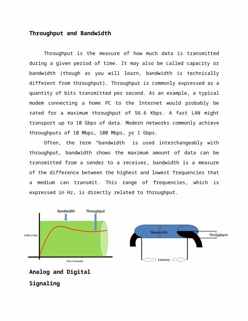
Often, the term “bandwidth” is used interchangeably with throughput, bandwidth shows
the maximum amount of data can be transmitted from a sender to a receiver, bandwidth is a
measure of the difference between the highest and lowest frequencies that a medium can
transmit. This range of frequencies, which is expressed in Hz, is directly related to throughput.
Analog and Digital SignalingOn a data network, information can be transmitted via one of two signaling methods:
analog or digital. Both types of signals are generated by electrical current, which is measured in
volts. The strength of an electrical signal is directly proportional to its voltage. Thus, when
network engineers talk about the strength of an analog or digital signal, they often refer to the
signal’s voltage.
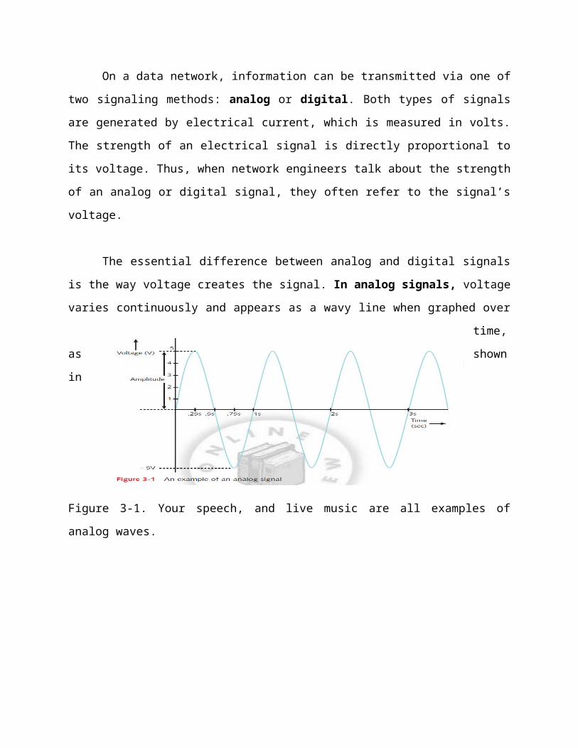
The essential difference between analog and digital signals is the way voltage creates the
signal. In analog signals, voltage varies continuously and appears as a wavy line when graphed
over time, as shown in Figure 3-1. Your speech, and live music are all examples of analog
waves.
An analog signal, like other waveforms, is characterized by four fundamental properties:
amplitude, frequency, wavelength, and phase.
1. Amplitude: Is a measure of its strength at any given point in time.
2. Frequency hertz (Hz): Is the number of times that a wave’s amplitude cycles from its starting
point, through its highest amplitude and its lowest amplitude, and back to its starting point over a
fixed period of time.
3. Wavelength: The distance between corresponding points on a wave’s cycle is called its
wavelength.
Wavelengths can be expressed in meters or feet. A wave’s wavelength is inversely proportional
to its frequency. In other words, the higher the frequency, the shorter the wavelength.
4. Phase: The term phase refers to the progress of a wave over time in relationship to a fixed
point.
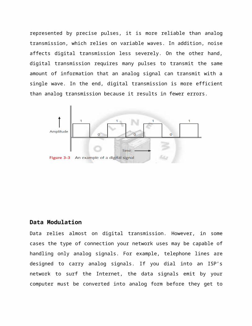
Digital signals are composed of pulses of precise, positive voltages and zero voltages. A
pulse of positive voltage represents a 1. A pulse of zero voltage (in other words, the lack of any
voltage) represents a 0. Because digital transmission involves sending and receiving only a
pattern of 1s and 0s, represented by precise pulses, it is more reliable than analog transmission,

which relies on variable waves. In addition, noise affects digital transmission less severely. On
the other hand, digital transmission requires many pulses to transmit the same amount of
information that an analog signal can transmit with a single wave. In the end, digital transmission
is more efficient than analog transmission because it results in fewer errors.
Data ModulationData relies almost on digital transmission. However, in some cases the type of connection your
network uses may be capable of handling only analog signals. For example, telephone lines are
designed to carry analog signals. If you dial into an ISP’s network to surf the Internet, the data
signals emit by your computer must be converted into analog form before they get to the phone
line. Later, they must be converted back into digital form when they arrive at the ISP’s access
server. A modem accomplishes this translation. The word modem reflects this device’s function
as a modulator/demodulator that is, it modulates digital signals into analog signals at the
transmitting end, then demodulates analog signals into digital signals at the receiving end.
Data modulation is a technology used to modify analog signals to make them suitable for
carrying data over a communication path. In modulation, a simple wave, called a carrier wave,
is combined with another analog signal to produce a unique signal that gets transmitted from
one node to another. Its purpose is to help to transmit information; in other words, it is only a
messenger. Another signal, known as the information or data wave, is added to the carrier
wave. When the information wave is added, it modifies one property of the carrier wave (for
example, the frequency, amplitude, or phase). The result is a new, blended signal that contains
properties of both the carrier wave and added data. When the signal reaches its destination, the
receiver separates the data from the carrier wave (demodulate).
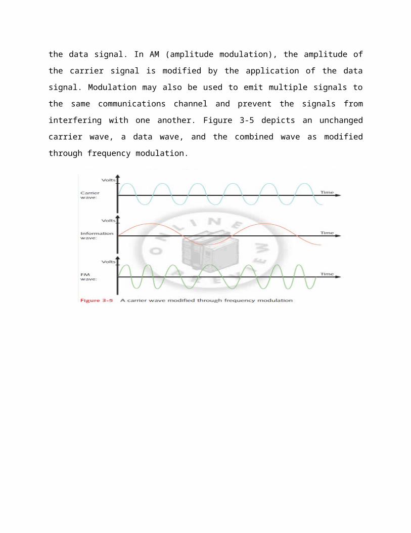
Modulation can be used to make a signal conform to a specific pathway, as in the case of
FM (frequency modulation) radio, in which the data must travel along a particular frequency. In
frequency modulation, the frequency of the carrier signal is modified by the application of the
data signal. In AM (amplitude modulation), the amplitude of the carrier signal is modified by the
application of the data signal. Modulation may also be used to emit multiple signals to the same
communications channel and prevent the signals from interfering with one another. Figure 3-5
depicts an unchanged carrier wave, a data wave, and the combined wave as modified through
frequency modulation.
MultiplexingA form of transmission that allows multiple signals to travel simultaneously over one
medium is known as multiplexing. To carry multiple signals, the medium’s channel is logically
separated into multiple smaller channels, or subchannels. Many different types of multiplexing
are available, and the type used in any given situation depends on what the media, transmission,
and reception equipment can handle. For each type of multiplexing, a device that can combine
many signals on a channel, a multiplexer (mux), is required at the sending end of the channel.
At the receiving end, a demultiplexer (demux) separates the combined signals and regenerates
them in their original form.
Multiplexing is commonly used on networks to increase the amount of data that can be
transmitted in a given time span.
Types of multiplexing:
1. Time Division Multiplexing (TDM), it is divides a channel into multiple intervals of
time, or time slots, then assigns a separate time slot to every node on the network and, in
that time slot, carries data from that node. For example, if five stations are connected to a
network over one wire, five different time slots are established in the communications
channel. Workstation A may be assigned time slot 1, workstation B time slot 2,
workstation C time slot 3, and so on. Time slots are reserved for their designated nodes
regardless of whether the node has data to transmit. If a node does not have data to send,
nothing is sent during its time slot. This arrangement can be inefficient if some nodes on
the network rarely send data. Figure 3-7 shows a simple TDM model.
2. Statistical multiplexing is similar to time division multiplexing, but rather than assigning
a separate slot to each node in succession, the transmitter assigns slots to nodes according to
priority and need. This method is more efficient than TDM, because in statistical multiplexing
time slots are unlikely to remain empty. To begin with, in statistical multiplexing, as in TDM,
each node is assigned one time slot. However, if a node doesn’t use its time slot,
statistical multiplexing devices recognize that and assign its slot to another node that needs
to send data. The contention for slots may be arbitrated according to use or priority or even
more sophisticated factors, depending on the network. Most importantly, statistical multiplexing
maximizes available bandwidth on a network. Figure 3-8 depicts a simple statistical
multiplexing system.
3. Wavelength Division Multiplexing (WDM)
Is a technology used with fiber-optic cable, In fiber-optic transmission, data is
represented as pulses of light, rather than pulses of electric current. WDM enables one fiber-optic
connection to carry multiple light signals simultaneously. Using WDM, a single fiber can
transmit as many as 20 million telephone conversations at one time.
In the first step of WDM, a beam of light is divided into up to 40 different carrier waves,
each with a different wavelength (and, therefore, a different color). Each wavelength represents a
separate transmission channel capable of transmitting up to 10 Gbps. Before transmission, each
carrier wave is modulated with a different data signal. Then, through a very narrow beam of
light, lasers emit the separate, modulated waves to a multiplexer. The multiplexer combines all
of the waves, in the same way that a prism can accept light beams of different wavelengths and
concentrate them into a single beam of white light. Next, another laser emit this multiplexed
beam to a strand of fiber. The fiber carries the multiplexed signals to a receiver, which is
connected to a demultiplexer. The demultiplexer acts as a prism to separate the combined
signals according to their different wavelengths (or colors). Then, the separate waves are sent to
their destinations on the network. If the signal risks losing strength between the multiplexer and
demultiplexer, an amplifier might be used to boost it. Figure 3-9 illustrates WDM transmission.
The form of WDM used on most modern fiber-optic networks is DWDM (dense
wavelength division multiplexing). In DWDM, a single fiber in a fiber-optic cable can carry
between 80 and 160 channels. DWDM is typically used on high-bandwidth or long-distance
WAN links, such as the connection between a large ISP and its (even larger) network service
provider.