08_E90 Entertain and Communication.qxd - Elegant … Entertain and Communication.pdf · Information...
41
Initial Print Date: 03/05 Table of Contents Subject Page Introduction to Information & Communication Technology . . . . . . .4 Audio Systems . . . . . . . . . . . . . . . . . . . . . . . . . . . . . . . . . . . . . . . . . . . . . . . .5 System Components and Features . . . . . . . . . . . . . . . . . . . . . . . . . . . . . . .6 Radios Overview . . . . . . . . . . . . . . . . . . . . . . . . . . . . . . . . . . . . . . . . . . . . .6 ‘Professional’ Radio (Rad2) . . . . . . . . . . . . . . . . . . . . . . . . . . . . . . . . . . . .7 Navigation System, Professional . . . . . . . . . . . . . . . . . . . . . . . . . . . . . . .7 Amplifiers and Speakers . . . . . . . . . . . . . . . . . . . . . . . . . . . . . . . . . . . . . .8 HiFi System . . . . . . . . . . . . . . . . . . . . . . . . . . . . . . . . . . . . . . . . . . . . . .9 HiFi System Circuit Diagram . . . . . . . . . . . . . . . . . . . . . . . . . . . . . .10 Top-HiFi System . . . . . . . . . . . . . . . . . . . . . . . . . . . . . . . . . . . . . . . . .12 Top HiFi System Circuit Diagram . . . . . . . . . . . . . . . . . . . . . . . . . .14 Antennas . . . . . . . . . . . . . . . . . . . . . . . . . . . . . . . . . . . . . . . . . . . . . . . . . .16 Radio Antennas . . . . . . . . . . . . . . . . . . . . . . . . . . . . . . . . . . . . . . . . .17 FM Antenna Diversity . . . . . . . . . . . . . . . . . . . . . . . . . . . . . . . . . . . .18 Roof Aerial . . . . . . . . . . . . . . . . . . . . . . . . . . . . . . . . . . . . . . . . . . . . . .20 SDARS Satellite Tuner . . . . . . . . . . . . . . . . . . . . . . . . . . . . . . . . . . . . . . .21 CD Changer . . . . . . . . . . . . . . . . . . . . . . . . . . . . . . . . . . . . . . . . . . . . . . . .22 Audio Jack . . . . . . . . . . . . . . . . . . . . . . . . . . . . . . . . . . . . . . . . . . . . . . . . .23 Service Information . . . . . . . . . . . . . . . . . . . . . . . . . . . . . . . . . . . . . . . . . . . .24 Radio Service Mode . . . . . . . . . . . . . . . . . . . . . . . . . . . . . . . . . . . . . . . . .24 Accessing Service Mode - Rad2 . . . . . . . . . . . . . . . . . . . . . . . . . .24 Information Available . . . . . . . . . . . . . . . . . . . . . . . . . . . . . . . . . . . . .24 Accessing Service Mode - CCC . . . . . . . . . . . . . . . . . . . . . . . . . . .25 Reset . . . . . . . . . . . . . . . . . . . . . . . . . . . . . . . . . . . . . . . . . . . . . . . . . . . . . .25 Interference in Radio Reception . . . . . . . . . . . . . . . . . . . . . . . . . . . . . .25 MP3/WMA Playback . . . . . . . . . . . . . . . . . . . . . . . . . . . . . . . . . . . . . . . .26 Bit Rate . . . . . . . . . . . . . . . . . . . . . . . . . . . . . . . . . . . . . . . . . . . . . . . . .27 Navigation System . . . . . . . . . . . . . . . . . . . . . . . . . . . . . . . . . . . . . . . . . .28 System Circuit Diagram . . . . . . . . . . . . . . . . . . . . . . . . . . . . . . . . . . . . . . . .29 System Components and Features . . . . . . . . . . . . . . . . . . . . . . . . . . . . . .30 CCC . . . . . . . . . . . . . . . . . . . . . . . . . . . . . . . . . . . . . . . . . . . . . . . . . . . . . .30 DVD Drive . . . . . . . . . . . . . . . . . . . . . . . . . . . . . . . . . . . . . . . . . . . . . .30 Audio CD Drive . . . . . . . . . . . . . . . . . . . . . . . . . . . . . . . . . . . . . . . . . .30 Housing . . . . . . . . . . . . . . . . . . . . . . . . . . . . . . . . . . . . . . . . . . . . . . . .30 E90 Entertainment and Communication Revision Date:
Transcript of 08_E90 Entertain and Communication.qxd - Elegant … Entertain and Communication.pdf · Information...
Initial Print Date: 03/05
Table of Contents
Subject Page
Introduction to Information & Communication Technology . . . . . . .4
Audio Systems . . . . . . . . . . . . . . . . . . . . . . . . . . . . . . . . . . . . . . . . . . . . . . . .5System Components and Features . . . . . . . . . . . . . . . . . . . . . . . . . . . . . . .6
Radios Overview . . . . . . . . . . . . . . . . . . . . . . . . . . . . . . . . . . . . . . . . . . . . .6‘Professional’ Radio (Rad2) . . . . . . . . . . . . . . . . . . . . . . . . . . . . . . . . . . . .7Navigation System, Professional . . . . . . . . . . . . . . . . . . . . . . . . . . . . . . .7Amplifiers and Speakers . . . . . . . . . . . . . . . . . . . . . . . . . . . . . . . . . . . . . .8
HiFi System . . . . . . . . . . . . . . . . . . . . . . . . . . . . . . . . . . . . . . . . . . . . . .9HiFi System Circuit Diagram . . . . . . . . . . . . . . . . . . . . . . . . . . . . . .10Top-HiFi System . . . . . . . . . . . . . . . . . . . . . . . . . . . . . . . . . . . . . . . . .12Top HiFi System Circuit Diagram . . . . . . . . . . . . . . . . . . . . . . . . . .14
Antennas . . . . . . . . . . . . . . . . . . . . . . . . . . . . . . . . . . . . . . . . . . . . . . . . . .16Radio Antennas . . . . . . . . . . . . . . . . . . . . . . . . . . . . . . . . . . . . . . . . .17FM Antenna Diversity . . . . . . . . . . . . . . . . . . . . . . . . . . . . . . . . . . . .18Roof Aerial . . . . . . . . . . . . . . . . . . . . . . . . . . . . . . . . . . . . . . . . . . . . . .20
SDARS Satellite Tuner . . . . . . . . . . . . . . . . . . . . . . . . . . . . . . . . . . . . . . .21CD Changer . . . . . . . . . . . . . . . . . . . . . . . . . . . . . . . . . . . . . . . . . . . . . . . .22Audio Jack . . . . . . . . . . . . . . . . . . . . . . . . . . . . . . . . . . . . . . . . . . . . . . . . .23
Service Information . . . . . . . . . . . . . . . . . . . . . . . . . . . . . . . . . . . . . . . . . . . .24Radio Service Mode . . . . . . . . . . . . . . . . . . . . . . . . . . . . . . . . . . . . . . . . .24
Accessing Service Mode - Rad2 . . . . . . . . . . . . . . . . . . . . . . . . . .24Information Available . . . . . . . . . . . . . . . . . . . . . . . . . . . . . . . . . . . . .24Accessing Service Mode - CCC . . . . . . . . . . . . . . . . . . . . . . . . . . .25
Reset . . . . . . . . . . . . . . . . . . . . . . . . . . . . . . . . . . . . . . . . . . . . . . . . . . . . . .25Interference in Radio Reception . . . . . . . . . . . . . . . . . . . . . . . . . . . . . .25MP3/WMA Playback . . . . . . . . . . . . . . . . . . . . . . . . . . . . . . . . . . . . . . . .26
Bit Rate . . . . . . . . . . . . . . . . . . . . . . . . . . . . . . . . . . . . . . . . . . . . . . . . .27
Navigation System . . . . . . . . . . . . . . . . . . . . . . . . . . . . . . . . . . . . . . . . . .28System Circuit Diagram . . . . . . . . . . . . . . . . . . . . . . . . . . . . . . . . . . . . . . . .29System Components and Features . . . . . . . . . . . . . . . . . . . . . . . . . . . . . .30
CCC . . . . . . . . . . . . . . . . . . . . . . . . . . . . . . . . . . . . . . . . . . . . . . . . . . . . . .30DVD Drive . . . . . . . . . . . . . . . . . . . . . . . . . . . . . . . . . . . . . . . . . . . . . .30Audio CD Drive . . . . . . . . . . . . . . . . . . . . . . . . . . . . . . . . . . . . . . . . . .30Housing . . . . . . . . . . . . . . . . . . . . . . . . . . . . . . . . . . . . . . . . . . . . . . . .30
E90 Entertainment and Communication
Revision Date:

Subject Page
Audio Board (ASK) . . . . . . . . . . . . . . . . . . . . . . . . . . . . . . . . . . . . . . .31Power Board . . . . . . . . . . . . . . . . . . . . . . . . . . . . . . . . . . . . . . . . . . . .31Gyro Sensor . . . . . . . . . . . . . . . . . . . . . . . . . . . . . . . . . . . . . . . . . . . .31HIP-Module (Host Independence Positioning Module) . . . . . . .31
Principles of Operation . . . . . . . . . . . . . . . . . . . . . . . . . . . . . . . . . . . . . . . . .33Navigation Mode . . . . . . . . . . . . . . . . . . . . . . . . . . . . . . . . . . . . . . . . . . . .34
Service Information . . . . . . . . . . . . . . . . . . . . . . . . . . . . . . . . . . . . . . . . . . . .35DVD . . . . . . . . . . . . . . . . . . . . . . . . . . . . . . . . . . . . . . . . . . . . . . . . . . . . . . .35Media Ejection . . . . . . . . . . . . . . . . . . . . . . . . . . . . . . . . . . . . . . . . . . . . .35Start-Up . . . . . . . . . . . . . . . . . . . . . . . . . . . . . . . . . . . . . . . . . . . . . . . . . . .35
Telephone . . . . . . . . . . . . . . . . . . . . . . . . . . . . . . . . . . . . . . . . . . . . . . . . . . .36System Circuit Diagram . . . . . . . . . . . . . . . . . . . . . . . . . . . . . . . . . . . . . . . .38Service Information . . . . . . . . . . . . . . . . . . . . . . . . . . . . . . . . . . . . . . . . . . . .40
Compatible Telephones . . . . . . . . . . . . . . . . . . . . . . . . . . . . . . . . . . . . .40Pairing a Handset . . . . . . . . . . . . . . . . . . . . . . . . . . . . . . . . . . . . . . . . . . .40v60i Phones . . . . . . . . . . . . . . . . . . . . . . . . . . . . . . . . . . . . . . . . . . . . . . . .40
Voice Recognition System . . . . . . . . . . . . . . . . . . . . . . . . . . . . . . . . . . .41TCU . . . . . . . . . . . . . . . . . . . . . . . . . . . . . . . . . . . . . . . . . . . . . . . . . . . . . . . . .41CCC . . . . . . . . . . . . . . . . . . . . . . . . . . . . . . . . . . . . . . . . . . . . . . . . . . . . . . . . .41

3E90 Communication
Entertainment and Communication
Model: E90
Production: From Start of Production
After completion of this module you will be able to:
• Identify the different audio systems available
• Access service mode on the RAD2
• Know the TCU variant offered as optional equipment
• Understand what systems can play back MP3/MWA files

4E90 Communication
Information and Communication Technology refers to various systems in the vehicle thatthat inform or entertain the driver and passengers.
Depending on the equipment configuration (BMW Assist), the IKT also serves the purpose of making available servicing-relevant data and sending messages in the case of emergency.
For the first time in this vehicle class, a fibre optics-based bus is used for data transmis-sion in information and communication applications (IKT). This bus is the so-calledMOST (Media Orientated Systems Transport) bus as already used on the E65, E60 andE63/4.
In this section you will be informed about the information and communication technolo-gy available in the new BMW3 Series (E90). It deals with the following topics:
• Audio systems
• Navigation systems
• Telephone systems
• Voice recognition systems
Introduction to Information & Communication Technology

5E90 Communication
Audio Systems
Two audio sources are offered on the E90. Both are on the MOST bus and have CDplaying capabilities.
The base version utilizes a single cd drive and a dual LCD line readout and is referred toas the RAD2 (‘Professional’ radio). This audio system can be ordered as a HiFi systemwith 180 Watt capability or upgraded to Top-HiFi Logic7 with 420 Watts of power.
The second audio source is the familiar Car Communication Computer (CCC orNavigation system, Professional). Because the CCC does not have an LCD readout, it utilized the CID as a visual monitor. A vehicle equipped with CCC will always comewith the Top-HiFi Logic7 system with 420 Watts of power as standard.
The following new features have been introduced:
• New 'Professional' radio with MOST capabilities (RAD2 and CCC)
• Additional audio input for external devices
• Playback of MP3 files (RAD2 Directly / CCC with CD Changer)

System Components and Features
Radios Overview
The E90 is equipped with RAD2 (‘Professional’ Radio) as standard equipment.
6E90 Communication
'Professional'radio
'Professional'navigationsystem
SA663 SA609
Designation CD-73, MD-73 CCCDisplay Two-line CID 8.8"Manufacturer Alpine Siemens VDO
Bus connection K-CAN, MOST K-CAN, MOSTAM tunerrange
SingleLW,MW
SingleLW,MW,SW
FM tuner (RDS) Single DoubleFM diversityCD Yes
YesYes
Yes Yes
Yes Yes
Yes Yes
Yes
Yes
Yes
Yes Planned
Yes
MD (instead ofCD)
--- ---
DVD ---MP3 playback
Audio jackAUX levelmatching
---
Top-HiFioperationTelephoneoperationCD changeroperation

7E90 Communication
‘Professional’ Radio (Rad2)The 'Professional' radio is a new radio for the MOST system network.
The radio combines the following features:
• Player for CD/MP3/WMA files • Built in single radio tuner
• Most bus gateway to the K-CAN • Liquid crystal display
• Board computer readout • Personal profile management
The MP3 directory structure is the same as that of a PC. Up to 8 directory levels can berepresented. A maximum of 255 directories and a total of 999 music tracks per CD canbe managed.
TE04-4453
Navigation System, ProfessionalThe 'Professional' navigation system is based on the CCC (car communication comput-er), the functions of which are already familiar from the E60 and E63/4.
The CCC combines the following control units in one housing:
• Navigation computer/GPS module; Map display and/or arrow view on CID (splitscreen)
• RDS double tuner
• Audio system controller (ASK)
• MOST gateway
• Interface to control display (LVDS)
• DVD player
• CD player
When the navigation system is not in use, its DVD drive can be used to play audio CDs.
Together with the controller and CID, the CCC forms the iDrive system.
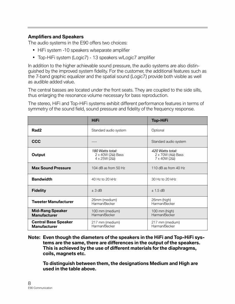
Amplifiers and SpeakersThe audio systems in the E90 offers two choices:
• HiFi system -10 speakers w/separate amplifier
• Top-HiFi system (Logic7) - 13 speakers w/Logic7 amplifier
In addition to the higher achievable sound pressure, the audio systems are also distin-guished by the improved system fidelity. For the customer, the additional features such asthe 7-band graphic equalizer and the spatial sound (Logic7) provide both visible as wellas audible added value.
The central basses are located under the front seats. They are coupled to the side sills,thus enlarging the resonance volume necessary for bass reproduction.
The stereo, HiFi and Top-HiFi systems exhibit different performance features in terms ofsymmetry of the sound field, sound pressure and fidelity of the frequency response.
Note: Even though the diameters of the speakers in the HiFi and Top-HiFi sys-tems are the same, there are differences in the output of the speakers.This is achieved by the use of different materials for the diaphragms,coils, magnets etc.
To distinguish between them, the designations Medium and High areused in the table above.
8E90 Communication
HiFi Top-HiFi
Rad2 Standard audio system Optional
CCC ---- Standard audio system
Output180 Watts total:
2 x 40W (2Ω) Bass4 x 25W (2Ω)
420 Watts total:2 x 70W (4Ω) Bass7 x 40W (2Ω)
Max Sound Pressure 104 dB as from 50 Hz 110 dB as from 40 Hz
Bandwidth 40 Hz to 20 kHz 30 Hz to 20 kHz
Fidelity ± 3 dB ± 1.5 dB
Tweeter Manufacturer 26mm (medium)Harman/Becker
26mm (high)Harman/Becker
Mid-Rang SpeakerManufacturer
100 mm (medium)Harman/Becker
100 mm (high)Harman/Becker
Central Base SpeakerManufacturer
217 mm (medium)Harman/Becker
217 mm (medium)Harman/Becker

HiFi SystemThe analogue 6-channel 'HiFi' amplifier has the same technical specifications as the onefitted in the E83. In the E90, however, it features settings specific to the E90 (diplexers,equalizing).
The HiFi amplifier is located behind the rear left side panel trim in the luggage compart-ment.
The audio signals are transmitted in analog form from the radios or navigation systems tothe HiFi amplifier. This amplifier amplifies the signals and transfers them to the speakers.
A total of 10 speakers are driven by 6 audio channels:
• A high-range and mid-range speaker in each front door
• A tweeter and a mid-range speaker on each side of the rear shelf
• A central bass speaker under each front seat
9E90 Communication
TE04-5287
6
6
4
47
1
3 2
5
5
3 2
Index Explanation Index Explanation
1 Rad2 5 Tweeter, front
2 Mid-range speakers, front 6 Tweeter, rear
3 Central woofers 7 HiFi amplifier
4 Mid-range speakers, rear
HiFi System Layout

HiFi System Circuit Diagram
10E90 Communication

Legend for HiFi System Circuit Diagram
11E90 Communication
Index Explanation Index Explanation
1 'Professional' radio (RAD 2) 16 Tweeter, rear right
4 Instrument cluster 17 HIFi Amplifier
5 Junction box control unit 18 Tweeter, rear left
6 Dynamic stability control 19 Mid-range speaker, rear left
7 Steering column switch cluster 21 Central base speaker, left
8 FM1, FM2 and FM3 aerials 23 Mid-range speaker, front left
9 AM aerial 24 Tweeter, front left
10 Antenna amplifier with diversity module MOST Media Orientated System Transport
11 Tweeter, front right HF High frequency signal
12 Mid-range speaker, front right ZF Intermediate frequency signal
13 Central base speaker, right Us Changeover voltage, AM/FMantenna diversity mode
15 Mid-range speaker, rear right Aux_In Audio input for additional audio sources
KLRad_on
Control signal or power supplyTel_
MuteRadio muting during telephone operation
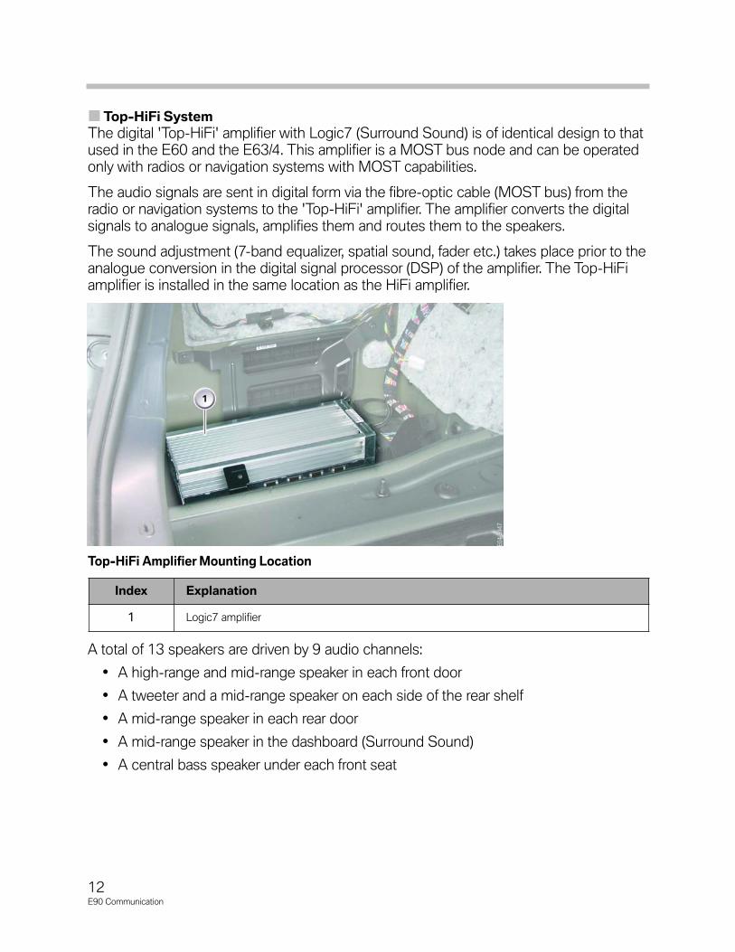
Top-HiFi SystemThe digital 'Top-HiFi' amplifier with Logic7 (Surround Sound) is of identical design to thatused in the E60 and the E63/4. This amplifier is a MOST bus node and can be operatedonly with radios or navigation systems with MOST capabilities.
The audio signals are sent in digital form via the fibre-optic cable (MOST bus) from theradio or navigation systems to the 'Top-HiFi' amplifier. The amplifier converts the digitalsignals to analogue signals, amplifies them and routes them to the speakers.
The sound adjustment (7-band equalizer, spatial sound, fader etc.) takes place prior to theanalogue conversion in the digital signal processor (DSP) of the amplifier. The Top-HiFiamplifier is installed in the same location as the HiFi amplifier.
A total of 13 speakers are driven by 9 audio channels:
• A high-range and mid-range speaker in each front door
• A tweeter and a mid-range speaker on each side of the rear shelf
• A mid-range speaker in each rear door
• A mid-range speaker in the dashboard (Surround Sound)
• A central bass speaker under each front seat
12E90 Communication
Top-HiFi Amplifier Mounting Location
Index Explanation
1 Logic7 amplifier

13E90 Communication
TE04-5288
6
6
4
47
1 9
8
3 2
5
5
3 2
10
10
Index Explanation Index Explanation
1 CCC 6 Tweeter, rear
2 Mid-range speakers, front 7 Top-HiFi amplifier
3 Central Woofers 8 CID
4 Mid-range speakers, rear 9 Mid-range speaker, front center
5 Tweeter, front 10 Mid-range speakers, rear doors
Top-HiFi System Layout

Top-HiFi System Circuit Diagram
14E90 Communication

Legend for Top-HiFi System Circuit Diagram
15E90 Communication
Index Explanation Index Explanation
1 Rad2 or CCC 16 Tweeter, rear right
2 CID 17 Top HiFi (Logic7) Amplifier
3 Controller 18 Tweeter, rear left
4 Instrument cluster 19 Mid-range speaker, rear left
5 Junction box control unit 20 Mid-range speaker, rear left (door)
6 Dynamic stability control 21 Central base speaker, left
7 Steering column switch cluster 22 Center speaker
8 FM1, FM2 and FM3 aerials 23 Mid-range speaker, front left
9 AM aerial 24 Tweeter, front left
10 Antenna amplifier with diversity module 25 Other MOST bus consumers
11 Tweeter, front right MOST Media Orientated System Transport
12 Mid-range speaker, front right HF High frequency signal
13 Central base speaker, right ZF Intermediate frequency signal
14 Mid-range speaker, rear right (door) Us Changeover voltage, AM/FMantenna diversity mode
15 Mid-range speaker, rear right Aux_In Audio input for additional audio sources
KLRad_on Control signal or power supply Tel_
Mute Radio muting during telephone operation
LVDS Low voltage differential signaling (digital) FS Most direct access (loop)

AntennasThe E90 can have up to 5 aerial systems depending on the optional equipment fitted:
• FM/AM radio (rear-window aerials)
• Digital radio (roof antenna)
• Navigation system (roof antenna)
• TV (rear-window aerials) - not for US
• Telephone (roof antenna) additionally:
- Bluetooth antenna in steering column trim panel for mobile telephone connection
- Emergency aerial in left rear wheel arch (only if premium package or option SA639)
In addition to those, there is also:
• Aerial for the remote control services (FBD)
• 6 aerials for the Comfort Access system (from 9/2005 option 322)
Note: An HBL filter is fitted suppresses interference from the third brake light.
16E90 Communication
Index Explanation Index Explanation
1 Antenna amplifier with diversity module 5 FM2 and TV2 aerial
2 FBD Aerial 6 FM1 antenna
3 Lockout circuit (filter) 7 Third brake light (HBL) filter
4 FM3 and TV1 aerial 8 AM aerial
Antenna Locations

17E90 Communication
Radio AntennasThe high-frequency signals from the radio transmitters are received via the rear-windowaerials (FM1, FM2, FM3 and AM).
The aerial amplifiers are in the Diversity module. There are separate ones for AM and FM.
The combined aerial amplifier and Diversity module is located on the headliner above therear window, concealed behind a cover.
Both aerial amplifiers are supplied with direct current when the radio is switched on (viaterminal Rad_On).
The high-frequency signals from the AM and FM aerials are passed via a ribbon cablefrom the rear window to the combined aerial amplifier and Diversity module.
Aerial Amplifier and Diversity Module
Index Explanation Index Explanation
1 AM/FM tuner signal connector (black) 4 TV1 signal (green) not for US
2 not for US 5 6-pin rear window aerial antenna
3 TV2 signal (brown) not for US 6 6-pin power supply and FBD connector

FM Antenna DiversityA quadruple FM aerial diversity system is fitted as standard on the E90.
FM antenna diversity comprises:
• FM1, FM2 and FM3 aerials
• FM4 aerial, formed by combining the signals from the FM1 and FM2 aerials
• FM antenna amplifier with antenna diversity module
For reasons of space, the rear window of the E90 can accommodate only three FM aerials. The FM4 aerial is not a physical component. To improve FM reception, the FM4aerial is created by overlaying the HF signals from the FM1 and FM2 aerials.
The signal quality of the currently selected FM antenna (FM1 to FM4) is evaluated andassessed in the diversity module. The next FM antenna is selected if the signal quality ofthe received radio station deteriorates in connection with the active antenna. Thechangeover takes place such that no interruption can be heard.
The high-frequency signal from the active FM aerial at any particular time is fed by theaerial amplifier and Diversity module via a co-axial cable to the tuner in the radio or navi-gation system. The signal is demodulated in the tuner and output in the form of an audiosignal through the speakers.
The radio or navigation system detects that a diversity module is installed and generatesthe changeover voltage Us and the intermediate frequency signal (ZF) necessary fordiversity operation. The ZF signal is analyzed by the electronic circuitry in the diversitymodule and is a copy of the currently selected radio station transmission on a fixed fre-quency of 10.7 MHz.
The changeover between AM reception, FM diversity mode and diagnosis mode iseffected by means of the DC voltage signal Us. This voltage is generated by the radio andused in the diversity module for evaluation purposes.
Diversity mode is active at Us = 2.5 V. AM mode is active at Us = 0 V, i.e. the FM1 anten-na is selected. Diagnosis mode is active at Us = 5 V.
In total, up to three signals are therefore applied on the coaxial cable simultaneously.
• HF signal (e.g. 87.5-108 MHz) from diversity module to radio
• Control DC voltage Us from the radio to the diversity module
• Intermediate frequency (fIF = 10.7 MHz) from the radio to the diversity module asthe basis for evaluating the quality of the RF signal.
18E90 Communication

19E90 Communication
Diversity Module Internal Schematic
Index Explanation Index Explanation
1Rear-window aerials FM1, FM2,
FM3 and AM7 Band-block filter for IF signal
2 AM aerial amplifier 8 Coaxial line to radio
3 Band-pass filter for AM signal 9 DC filter
4Aerial changeover switch for FM
aerials10 Diversity electronics
5 FM aerial amplifier 11 Band-pass filter for IF signal
6 Band-pass filter for FM signal 12 Demodulator with signal evaluation based on level and noise component
KLRad_on
Control signal or switched voltage supply from radio HF RF signal to radio
Us Antenna diversity changeovervoltage from radio ZF IF signal from radio

Roof AerialThere are two different variants of roof antenna for the E90:
• Vehicle equipped with TCU - GPS antenna needed for telematic feature
• Vehicle equipped with SDARS (Satellite Digital Radio Service - Sirius)
The roof aerial for SDARS reception has a larger housing compared with the version with-out satellite radio capability.
Specifically, the roof aerial for all possible equipment options on the US version comprises:
• Mobile phone aerials
• Telematic Control Unit (TCU) telephone aerials
• GPS antenna
• SDARS aerial for satellite reception
• SDARS aerial for terrestrial reception
20E90 Communication
SDARS Roof Aerial
Index Explanation
1 Telephone aerials for mobile phoneand Telematic Control Unit (TCU)
2 SDARS aerial for satellite reception
3 GPS antenna
4 SDARS aerial for terrestrial reception
5 GPS signal connectorcolor code: blue
6 SDARS signal, terrestrial
7 Telephone signal: connectorcolor code: Bordeaux violet
8 SDARS signal, satellite
9 Telephone signal: connectorcolor code: Grey

21E90 Communication
SDARS Satellite TunerThe SDARS satellite radio is the same as the satellite tuner fitted on the E60, E61, E63and E64.
It enables reception of digital radio signals. These are of a higher quality that analog trans-missions.
Advantages of digital satellite radio:
• Reception of same radio station across the entire US mainland (excluding Alaska)
• Digital reception of music, news and talk stations
• Wide choice of available music genres
• No commercial breaks
• Digital signal transmission provides greater immunity to external interference
Only the SDARS system developed by Sirius Satellite Radio is supported. This usesthree satellites which follow an elliptical orbit around the Earth. Because of the arrange-ment of the orbits, there are always two satellites over the reception area.
In large urban areas where there are obstructions (e.g. tower blocks, tunnels) or in situa-tions where there are topographical features (e.g. mountains) that block the satellite sig-nals, terrestrial transmitters are used to relay the signals.
The separate satellite tuner is necessary because the signals are transmitted in the giga-hertz band (microwave band).
The satellite tuner is located in the trunk above the recess, on the left (when viewed fromthe rear) next to the Telematic Control Unit (TCU).
Location of SDARS Tuner and TCU

CD ChangerAll E90 vehicles come pre-wired for CD changer.
The option SA672 for the E90 is a new "CD changer for 6 CDs" (CDC). The CD changeris a MOST network node and differs from the MOST-compatible CD changer on the E60and E63/4 by virtue of its support for MP3 files and WMA files.
The CD changer is located behind a flap on the left in the luggage compartment.
If the vehicle is equipped with the HiFi audio system, the digital data of the CD is sent viathe MOST bus to the radio or navigation system. Here they are converted to analog dataand output via the amplifier and the speakers.
If a 'Top-HiFi' system (Logic7) is installed, the audio data is transmitted in digital form viathe MOST bus from the CD changer directly to the Top-HiFi amplifier, from where it isoutput. This direct transmission bypassing the radio and the navigation system is possibleas data conversion and sound adjustment take place exclusively in the Top-HiFi amplifier.
The CD changer supports playback of MP3 CDs. The MP3 files are decoded in the CDchanger.
Note: Because MP3s are compressed audio files, it can take the player up to 20 seconds to decompress and read the information from a CD beforeaudio is heard.
The fibre optic conductors for connecting the CD changer are arranged at the fiber opticsconnector in the luggage compartment such that they are not incorporated in the MOSTring. After retrofitting a CD changer, the fibre optics conductors for the CD changerpreparation are unplugged at the fibre optics connector and connected to the MOST ring.Coding of the system will be necessary.
22E90 Communication
23E90 Communication
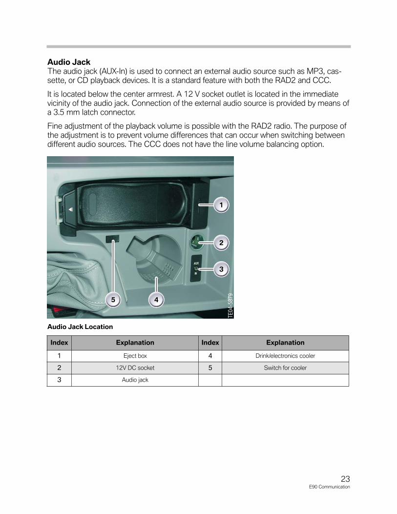
Audio JackThe audio jack (AUX-In) is used to connect an external audio source such as MP3, cas-sette, or CD playback devices. It is a standard feature with both the RAD2 and CCC.
It is located below the center armrest. A 12 V socket outlet is located in the immediatevicinity of the audio jack. Connection of the external audio source is provided by means ofa 3.5 mm latch connector.
Fine adjustment of the playback volume is possible with the RAD2 radio. The purpose ofthe adjustment is to prevent volume differences that can occur when switching betweendifferent audio sources. The CCC does not have the line volume balancing option.
Audio Jack Location
Index Explanation Index Explanation
1 Eject box 4 Drink/electronics cooler
2 12V DC socket 5 Switch for cooler
3 Audio jack
Service Information
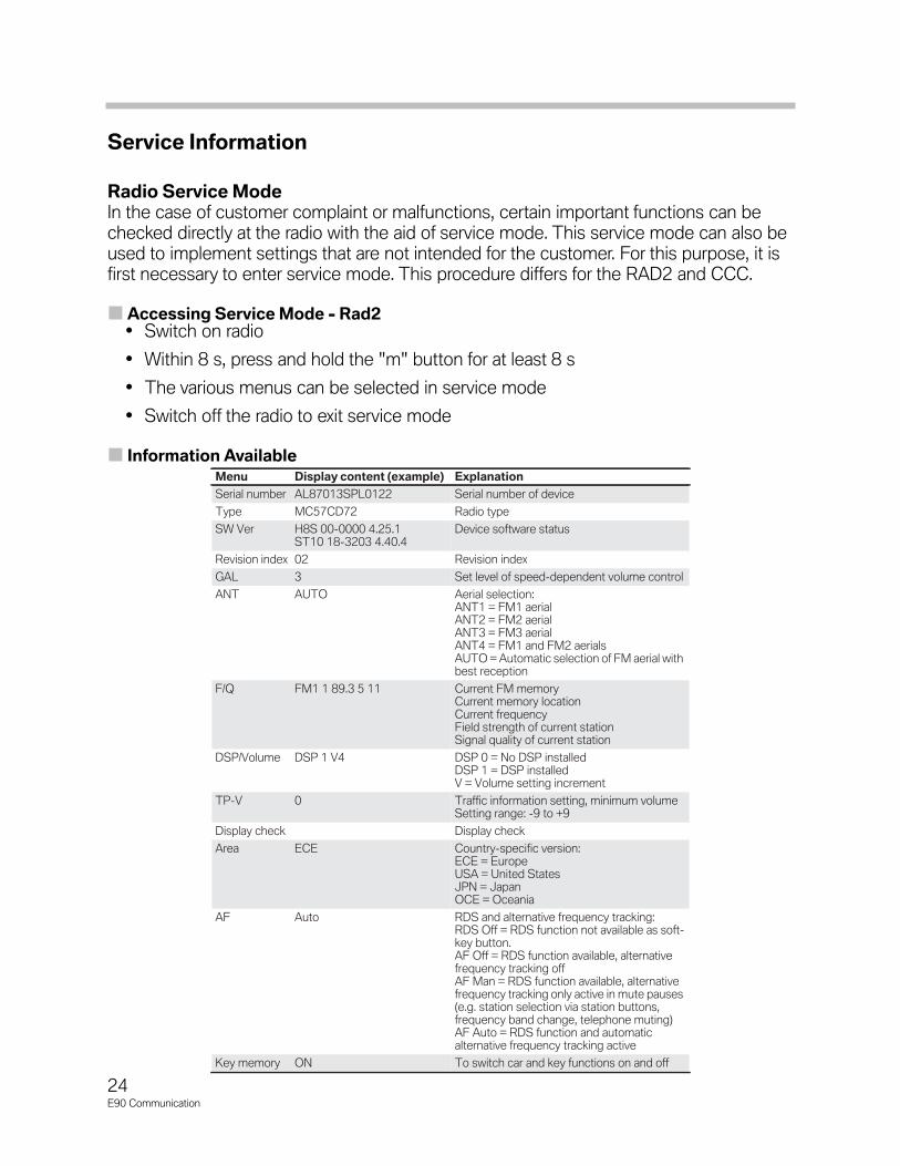
Radio Service ModeIn the case of customer complaint or malfunctions, certain important functions can bechecked directly at the radio with the aid of service mode. This service mode can also beused to implement settings that are not intended for the customer. For this purpose, it isfirst necessary to enter service mode. This procedure differs for the RAD2 and CCC.
Accessing Service Mode - Rad2• Switch on radio
• Within 8 s, press and hold the "m" button for at least 8 s
• The various menus can be selected in service mode
• Switch off the radio to exit service mode
Information AvailableMenu Display content (example) ExplanationSerial number AL87013SPL0122 Serial number of deviceType MC57CD72 Radio typeSW Ver H8S 00-0000 4.25.1
ST10 18-3203 4.40.4Device software status
Revision index 02 Revision indexGAL 3 Set level of speed-dependent volume controlANT AUTO Aerial selection:
ANT1 = FM1 aerialANT2 = FM2 aerialANT3 = FM3 aerialANT4 = FM1 and FM2 aerialsAUTO = Automatic selection of FM aerial withbest reception
F/Q FM1 1 89.3 5 11 Current FM memoryCurrent memory locationCurrent frequencyField strength of current stationSignal quality of current station
DSP/Volume DSP 1 V4 DSP 0 = No DSP installedDSP 1 = DSP installedV = Volume setting increment
TP-V 0 Traffic information setting, minimum volumeSetting range: -9 to +9
Display check Display checkArea ECE Country-specific version:
ECE = EuropeUSA = United StatesJPN = JapanOCE = Oceania
AF Auto RDS and alternative frequency tracking:RDS Off = RDS function not available as soft-key button.AF Off = RDS function available, alternativefrequency tracking offAF Man = RDS function available, alternativefrequency tracking only active in mute pauses(e.g. station selection via station buttons,frequency band change, telephone muting)AF Auto = RDS function and automaticalternative frequency tracking active
Key memory ON To switch car and key functions on and off
24E90 Communication

25E90 Communication
Accessing Service Mode - CCCThe only information available in the CCC are software, hardware, and system statusnumbers. The information is primarily intended for equipment development purposes.More is planned for the future.
• Open Start menu
• Press and hold Controller for at least 10 s
• Move Controller 3 stops to the right
• Move Controller 3 stops to the left
• Move Controller 1 stop to the right
• Move Controller 1 stop to the left
• Move Controller 1 stop to the right
• Press Controller once
To exit Service mode press the Menu button.
ResetThe RAD2 can only be reset by the following procedures:
• Switch system ON/OFF
• Disconnect from vehicle electrical system
• BMW diagnosis system
There is no button or key combination on the device for performing a reset.
The 'Professional' navigation system (CCC) can be reset by simultaneously pressing andholding the eject buttons on the DVD and CD player and the rotary push-button forapproximately 10 s. The CID becomes blank. The CCC is then restarted.
3 The MOST gateway ('Professional' radio, M-ASK or CCC) is muted for 2 s when reset-ting a MOST control unit. 1
Interference in Radio ReceptionCheck the following in the event of interference in radio reception:
• Power supply terminal Rad_On for the antenna amplifiers in the diversity module.
• Antenna connector at diversity module
• Antenna connector at radio or navigation system
Note: Care must be taken as the antenna plug connection may be damaged dueto the restricted package space behind the CCC.
TE04-4271

Service Concept
The following are replaced as complete units:
• 'Business CD' radio
• 'Professional' radio
• 'Business' navigation system (M-ASK)
The service concept of the CCC permits replacement of individual assemblies. It is basedon the concept implemented on the E60. The following assemblies can be replaced:
• Fan
• CD and DVD player
• Front panel
• HIP, gyro sensor
• Tuner/audio board
Observe the electro-static discharge (ESD) guidelines when replacing components.
MP3/WMA Playback
Note: The information provided in the following is of a general nature and notspecific to BMW.
MP3 stands for MPEG Layer 3 and is a compression method for audio data whichachieves very high compression ratios. MP3 makes use of a phenomenon that is associ-ated with psychoacoustics: Human beings do not hear everything that theoretically couldbe heard - in any case not consciously. Based on the characteristics of human hearing,the MP3 inventors at the German Fraunhofer Institute have developed perception-adapt-ed audio coding whereby part of the digital sound information normally found on the CDis simply omitted. These are sounds that most people do not consciously perceive, e.g.very high or very low sounds. In addition, components of the sound signals are omittedthat are of no significance with regard to the sound impression but enabling the very highcompression values.
MPEG is the abbreviation for Moving Picture Experts Group. The experts group is anorganization that has created standards for the compression of film data. The standardsfor audio compression were later added.
MPEG layer 1 and layer 2 are the predecessors of MP3. They achieve compression rateswhich, however, do not approach those of Layer 3. Layer 1, for example, is used in con-nection with digital music cassettes and Layer 2 for DAB (Digital Audio Broadcast). Allthree compression methods (Codecs, see below) are downward compatible, i.e. a Layer-3 decoder will also play files that are coded in accordance with Layer 1 or Layer 2.
The computing power for MPEG Layer 1 to 3 is to a high degree asymmetric. Thismeans that the computing power for MP3encoding is substantially higher than for MP3decoding.
26E90 Communication

Since all the values achieved during the coding procedure are stored in the MP3 file, thework of the decoder is restricted to interpreting these values. All three layers support thefollowing sample rates: 32 kHz, 44.1 kHz or 48 kHz. As part of MPEG audio coding, a fil-ter array converts the audio signal to be encoded from the time range to the frequencyrange. During this procedure it is initially subdivided into 32 frequency ranges (sub-bands). Prior to MPEG Layer 2, all 32 sub-bands had the same width of 625 Hz. Onlywith the advent of Layer 3 have the sub-bands been adapted to the characteristics of thehuman ear (psychoacoustic model). The audio signal subdivided into frequency rangesprovides the algorithm with distinctly more working area or depth for data reduction thanthe uniform audio signal.
The MP3 encoder examines each sub-band individually and removes frequencies thatare deemed dispensable based on the fundamental psychoacoustic model and com-presses the remaining audio data.
Bit RateCompression of audio data using the MP3 method reduces the data volume correspond-ing to the selected target quality to a fraction of the original volume. A decisive factor gov-erning the music quality of an MP3 file is the data transmission rate - referred to as the bitrate. In connection with MP3, the bit rate is measured in kiloBits per second. The higherthe bit rate, the higher the quality of the result. However, this also increases the size of thedata volume to be stored.
Overview of MP3 quality stages
There are both fixed and variable bit rates which, however, are not supported by all MP3players. The traditional method of audio coding CBR (Constant Bit Rate) maintains a con-stant bit rate during the entire recording. In connection with the variable bit rate method(VBR), the bit rate drops to a lower level when a section in a song contains little soundinformation. As a result, the bit rate is frequently reduced to 32 kBit/s or less. In sectionswith large quantities of sound information, the bit rate increases to a specified maximumwhich is normally at 128 or 192 kBit/s. The advantage of the variable bit rate is an overallbetter sound quality with reduced file sizes.
While MP3 is better suited for coding at higher bit rates, the WMA format (WindowsMedia Audio) is appropriate for lower bit rates. When using WMA format, even recordingswith a bit rate of only 64 kBit/s sound acceptable. The data loss at a constant bit rate isless noticeable than in an MP3 file. However, outstanding bass reproduction at 64 kBit/scannot be achieved in any format. WMA is much better suited than MP3 for ultralow bitrates (e.g. 16 kBit/s).
Sound quality Mode Bit rate Compression ratioTelephone Mono 8 kBit/s 96:1Better than SW radio Mono 16 kBit/s 48:1Better than MW radio Mono 32 kBit/s 24:1Similar to UHF radio Stereo 56 to 64 kBit/s 26:1 to 24:1Approaching CD quality Stereo 96 to 112 kBit/s 16:1 to 14:1CD quality Stereo 128 to 192 kBit/s 12:1 to 8:1
27E90 Communication
28E90 Communication
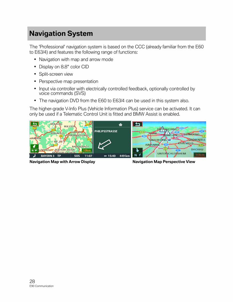
Navigation System
The 'Professional' navigation system is based on the CCC (already familiar from the E60to E63/4) and features the following range of functions:
• Navigation with map and arrow mode
• Display on 8.8" color CID
• Split-screen view
• Perspective map presentation
• Input via controller with electrically controlled feedback, optionally controlled byvoice commands (SVS)
• The navigation DVD from the E60 to E63/4 can be used in this system also.
The higher-grade V-Info Plus (Vehicle Information Plus) service can be activated. It canonly be used if a Telematic Control Unit is fitted and BMW Assist is enabled.
Navigation Map with Arrow Display Navigation Map Perspective View
29E90 Communication
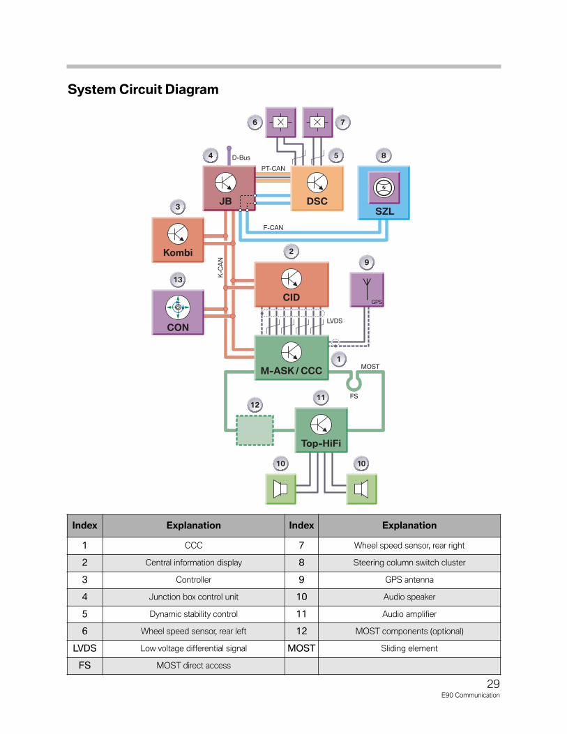
System Circuit Diagram
JB DSC
PT-CAN
D-Bus
F-CAN
K-CAN
Kombi
Top-HiFi
CONLVDS
CID
M-ASK / CCC
GPS
MOST
FS
SZL
TE04-4860
4 5 8
6 7
3
9
2
12
1010
11
13
1
Index Explanation Index Explanation
1 CCC 7 Wheel speed sensor, rear right
2 Central information display 8 Steering column switch cluster
3 Controller 9 GPS antenna
4 Junction box control unit 10 Audio speaker
5 Dynamic stability control 11 Audio amplifier
6 Wheel speed sensor, rear left 12 MOST components (optional)
LVDS Low voltage differential signal MOST Sliding element
FS MOST direct access

System Components and Features
This section describes the two navigation systems available on the E90. With few excep-tions, with regard to function, display and operation, these navigation systems correspondto the navigation systems used in the E60.
The navigation systems is made up of the following components:
• Navigation computer with GPS receiver and yaw rate sensor in the M-ASK or CCCcontrol unit
• GPS antenna
• Double tuner (radio/TMC data)
• DVD-Drive with Navigation DVD
Additional information:
• Wheel speed sensor information from DSC control unit (bus message)
• Reverse gear signal from footwell module (bus message)
CCC
30E90 Communication
Housing The car communication computer isaccommodated in an aluminiumcasing. The size of the car communi-cation computer corresponds to tworadio DIN casings.
Audio CD Drive The following types of CD can beplayed on the CD-ROM drive:
- Audio CD
DVD Drive When the navigation system is not inuse, the DVD drive can also be usedto play audio CDs or audio CD-ROMs with MP3 files.
31E90 Communication
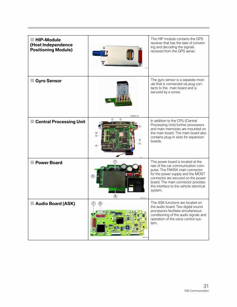
HIP-Module (Host Independence Positioning Module)
The HIP module contains the GPSreceiver that has the task of convert-ing and decoding the signalsreceived from the GPS aerial.:
Gyro Sensor The gyro sensor is a separate mod-ule that is connected via plug con-tacts to the main board and issecured by a screw.
Central Processing Unit In addition to the CPU (CentralProcessing Unit) further processorsand main memories are mounted onthe main board. The main board alsocontains plug-in slots for expansionboards.
Power Board The power board is located at the rear of the car communication com-puter. The FAKRA main connectorfor the power supply and the MOSTconnector are secured on the powerboard. The main connector providesthe interface to the vehicle electricalsystem.
Audio Board (ASK) The ASK functions are located onthe audio board. Two digital soundprocessors facilitate simultaneousconditioning of the audio signals andoperation of the voice control sys-tem.

32E90 Communication
Back View of CCC
Index Explanation Index Explanation
1 12-pin, left (AUX signal, fan) 7 Cover for expansion card
2 12-pin, right (not for US) 8 LVDS connection
3 16-pin 9 GPS antenna
4 MOST interface 10 Fan motor
5 Cover for expansion card 11 AM, FM antenna
6 Fan motor connection
Index Explanation
1 Audio board
2 Power board
3 Main board
Inside Components of CCC

33E90 Communication
Principles of Operation
Each satellite transmits messages with the following (simplified) information:
• Number of the satellite
• Current position of the satellite
• Message time
The satellite additionally broadcasts so-called orbit (path) and almanac data. These orbitand almanac data are stored in the navigation system and used for subsequent calcula-tions to enable fast acquisition of the currently available satellites. Almanac data containinformation on the orbits of all satellites, time correction factors and atmospheric delayparameters.
To determine the position, the GPS data are received by the GPS antenna in the antennabase and routed via a coaxial cable to the navigation computer (CCC). The GPS data aredecoded.
To determine the location, the navigation system compares the time at which the signalwas sent with the time at which the signal was received. The distance of the satellite canbe calculated from this time difference. The time calculations are based on a highly accu-rate atomic clock (UTC: Universal Time Coordinated).
The current position can now be determined by adding measurements from othersatellites. The GPS receiver can determine its position on the earth's surface with the aid of at least three satellites. This process is known as "2D position fix". Two dimensionalbecause the receiver must assume that it is located directly on the earth's surface. Theabsolute spatial position can be determined with the aid of four or more satellites ("3Dposition fix"). The altitude is necessary, for example, on multi-tier road junctions and intersections.
Note: A clear view of the sky is necessary for the reception of GPS data. Rain orsnow normally do not interfere with reception. However, a very densecover of wet leaves or shadow areas such as high-sided buildings, rowsof trees may impair reception.
In addition, depending on the time of day, there may be fluctuations insatellite reception at one location during a 24 hour period (example:Munich 5-10 satellites). This is due to the orbits of the satellites.
From these satellite signals, the navigation system calculates
• longitude
• latitude
• altitude from the satellite data.
Based on repeated measurements, the direction of movement and speed can also becalculated by way of GPS.
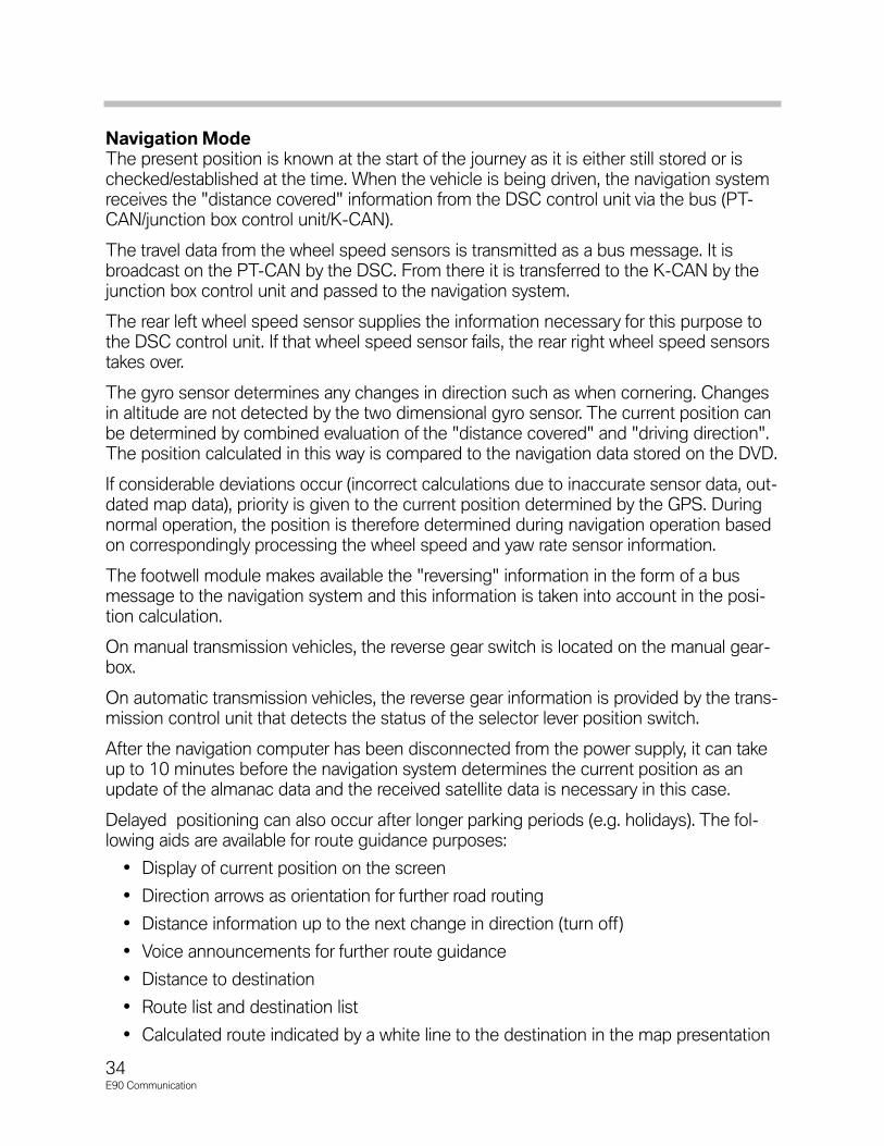
Navigation ModeThe present position is known at the start of the journey as it is either still stored or ischecked/established at the time. When the vehicle is being driven, the navigation systemreceives the "distance covered" information from the DSC control unit via the bus (PT-CAN/junction box control unit/K-CAN).
The travel data from the wheel speed sensors is transmitted as a bus message. It isbroadcast on the PT-CAN by the DSC. From there it is transferred to the K-CAN by thejunction box control unit and passed to the navigation system.
The rear left wheel speed sensor supplies the information necessary for this purpose tothe DSC control unit. If that wheel speed sensor fails, the rear right wheel speed sensorstakes over.
The gyro sensor determines any changes in direction such as when cornering. Changesin altitude are not detected by the two dimensional gyro sensor. The current position canbe determined by combined evaluation of the "distance covered" and "driving direction".The position calculated in this way is compared to the navigation data stored on the DVD.
If considerable deviations occur (incorrect calculations due to inaccurate sensor data, out-dated map data), priority is given to the current position determined by the GPS. Duringnormal operation, the position is therefore determined during navigation operation basedon correspondingly processing the wheel speed and yaw rate sensor information.
The footwell module makes available the "reversing" information in the form of a busmessage to the navigation system and this information is taken into account in the posi-tion calculation.
On manual transmission vehicles, the reverse gear switch is located on the manual gear-box.
On automatic transmission vehicles, the reverse gear information is provided by the trans-mission control unit that detects the status of the selector lever position switch.
After the navigation computer has been disconnected from the power supply, it can takeup to 10 minutes before the navigation system determines the current position as anupdate of the almanac data and the received satellite data is necessary in this case.
Delayed positioning can also occur after longer parking periods (e.g. holidays). The fol-lowing aids are available for route guidance purposes:
• Display of current position on the screen
• Direction arrows as orientation for further road routing
• Distance information up to the next change in direction (turn off)
• Voice announcements for further route guidance
• Distance to destination
• Route list and destination list
• Calculated route indicated by a white line to the destination in the map presentation
34E90 Communication

Service Information
DVDThe navigation DVD of the 'Professional' navigation system (CCC) are compatible withother vehicles (e.g. E60) with the same equipment (CCC).
Note: If the navigation DVD is not recognized although the correct DVD is loaded in theplayer, the DVD should be removed and reinserted.
Media EjectionIf the navigation DVD is not ejected during normal operation by pressing the Eject button,carry out the following procedure:
• Reset CCC
• Press the Eject button several times during start-up
Alternatively, the system reset can be activated by means of the BMW diagnosis system(control unit functions).
Note: If a DVD does not want to eject from the CCC, Do NOT FORCE it out. No mechanical emergency release is provided on the DVD player toremove media.
Start-UpAfter disconnecting the battery, due to the necessary data transmission, it may take up to10 minutes before the navigation system correctly displays the current position.
35E90 Communication

36E90 Communication
Telephone
The E90 is equipped with the same TCU that is found in the E60 and E63/4 vehiclesonly if option code SA639 (Assist or Premium Package) is ordered.
The range of functions offered are as follows:
• The Telematic Control Unit is fitted as standard in order to provide the Telematicfunctions Emergency call (E-call) and Breakdown call (B-call)
• Dual band 800 MHz and 1900 MHz
• Combined NAD (network access device) transceiver module for the:- analog AMPS (American Mobile Phone Standard)- digital CDMA (Code Division Multiplex Algorithm) standard
Two different equipment levels are offered for the American market:
• Telematic Control Unit with Telematic functions Emergency call (E-Call) andBreakdown call (B-Call) without base plate or snap-in adapter.
• Telematic Control Unit with Telematic functions Emergency call (E-Call) andBreakdown call (B-Call) with base plate and snap-in adapter for a supportedBluetooth compatible mobile phone.
The telematic control unit is factory-programmed as "active" for Bluetooth.Consequently, any supported mobile phone can be linked to the vehicle.
The customer also has the facility for charging the mobile phone in the vehicle and making calls via the external aerial. The external aerial reduces the radiation exposureinside the vehicle.
There are optional components available for the TCU:
• Base plate
• Snap-in adapter for Bluetooth-compatible mobile phone
• Compensator (optional)
Location of SDARS Tuner and TCU

37E90 Communication
The Telematic Control Unit supports
• Telematic
• TeleService
• BMW Assist
The TCU has an embedded phone that can call out for these services as longas the vehicle is in an area with cellular phone coverage.
The Telematic option provides the following:
• Emergency-call button with emergency-call indicator lamp
• SOS speaker
• SOS antenna
The telephone aerials for TCU and mobile phone are integrated in the roof aerial.There is an emergency backup antenna on the rear parcel shelf.
The Bluetooth antenna is located behind the steering column trim panel.
The hands-free microphone for telephone calls and voice control of the telephoneis in the roof function module (FZD) which is located on the driver's side.
Index Explanation
1 RAD2
2 Instrument cluster
3 MFL
4 MRS 5
5 Roof aerial (GPS)
6 Wheel speed sensors (x2)
7 SOS Antenna
8 Roof aerial (TCU)
9 TCU
10 FZD
11 SOS speaker
12 Bluetooth antenna
13 Snap in adapter with mobile phone
14 line compensator(optional)
15 Roof aerial (telephone cradle)
16 Audio speaker
17 CAS2
TCU IPO

System Circuit Diagram
38E90 Communication

39E90 Communication
Legend for System Circuit Diagram
Index Explanation Index Explanation
1 RAD2 13 Telematic control unit
2 Multiple restraint system 5 14 SOS antenna
3 Instrument cluster 15 Telephone aerial (TCU)
4 Junction box control unit 16Roof function module (driver's-sidemicrophone, emergency-call button with emergency-call indicator lamp)
5 Dynamic stability control 17 SOS speaker
6 Wheel speed sensor, left 18 Base plate
7 Wheel speed sensor, right 19 Snap-in adapter with mobile phone
8 Steering column switch cluster 20 Telephone aerial (mobile phone)
9 GPS antenna 21 Line compensator (optional)
10 Audio speaker 22 Bluetooth antenna
11 Audio amplifier 23 Car access system 2
12 MOST components (optional) MOST Media Orientated System Transport
13 Vehicle wake-up signal FS Service port MOST bus loop
DFA_VL Wheel speed signal, front left DFA_VR Wheel speed signal, front right
Mic+ Microphone, positive Mic- Microphone, negative
SOS LED Emergency-call indicator lamp SOS Emergency call signal
Cradle On ON signal for the charger electronics in the snap-in adapter
CradleKey
Call accept/transfer/pairing button
Tel_On Telephone ON signal for compensator
Service Information
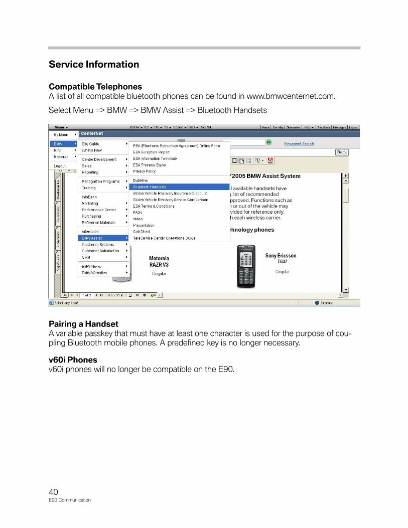
Compatible TelephonesA list of all compatible bluetooth phones can be found in www.bmwcenternet.com.
Select Menu => BMW => BMW Assist => Bluetooth Handsets
Pairing a HandsetA variable passkey that must have at least one character is used for the purpose of cou-pling Bluetooth mobile phones. A predefined key is no longer necessary.
v60i Phonesv60i phones will no longer be compatible on the E90.
40E90 Communication
41E90 Communication
The E90 has two different variants of voice control:
• Internal of the TCU
• Internal of the CCC
TCU
Voice control for telephone functions comes as standard with all telephone systems. Thevoice control capability is achieved by means of software on the telephone control unit.
Voice control comprises the telephone function and a voice-controlled phone book thatis separate from the address book on the mobile phone. Up to 50 names and telephonenumbers can be stored.
The telephone book managed by means of voice control cannot be transferred to themobile phone.
Note: The notepad function previously available with the ULF is not availableon the E90.
The microphone for voice control of the telephone is located in the roof functions centeron the driver's side. It is connected to the telephone control unit.
CCC
A more comprehensive voice recognition system is available with the option SA609('Professional' navigation system) as the voice recognition system is realized as softwarein the CCC.
Many of the functions that are otherwise selected via the controller in the CID can beoperated by means of voice commands.
The microphone is located in the roof functions center on the passenger's side and isconnected directly to the CCC.
The language of the voice recognition system cannot be changed in the CID. The lan-guage that can be selected in the CID (one of three languages) refers only to the displaytext and the announcement language for the navigation system.
During the CCC programming procedure, the language of the voice recognition systemis programmed corresponding to the vehicle order (country assignment). The languagecannot be easily changed over as for the display language due to the size of the softwarepackage.
Voice Recognition System