08 - 5 Star Timbers · #08 • Stairs, Balustrades and Handrails Class 1 Buildings – Construction...
56
08 Technical Design Guide issued by Forest and Wood Products Australia Stairs, Balustrades and Handrails Class 1 Buildings - Construction
-
Upload
truongkhanh -
Category
Documents
-
view
216 -
download
0
Transcript of 08 - 5 Star Timbers · #08 • Stairs, Balustrades and Handrails Class 1 Buildings – Construction...

08
Technical Design Guide issued by Forest and Wood Products Australia
Stairs, Balustrades and HandrailsClass 1 Buildings - Construction

WoodSolutions is an industry initiative designed to provide independent, non-proprietary information about timber and wood products to professionals and companies involved in building design and construction.
WoodSolutions is resourced by Forest and Wood Products Australia (FWPA). It is a collaborative effort between FWPA members and levy payers, supported by industry peak bodies and technical associations.
This work is supported by funding provided to FWPA by the Commonwealth Government.
ISBN 978-1-921763-16-8
Prepared by: Colin MacKenzie Timber Queensland Limited
First produced: April 2007 Revised: May 2012, October 2013
01
Technical Design Guide issued by Forest and Wood Products Australia
Timber-framed Constructionfor Townhouse Buildings Class 1aDesign and construction guide for BCA compliant sound and fire-rated construction
Timber-framed Construction
04
Technical Design Guide issued by Forest and Wood Products Australia
Building with Timber in Bushfire-prone AreasBCA Compliant Design and Construction Guide
09
Technical Design Guide issued by Forest and Wood Products Australia
Timber FlooringDesign guide for installation
© 2012 Forest and Wood Products Australia Limited. All rights reserved.
These materials are published under the brand WoodSolutions by FWPA.
IMPORTANT NOTICE
Whilst all care has been taken to ensure the accuracy of the information contained in this publication, Forest and Wood Products Australia Limited and WoodSolutions Australia and all persons associated with them (FWPA) as well as any other contributors make no representations or give any warranty regarding the use, suitability, validity, accuracy, completeness, currency or reliability of the information, including any opinion or advice, contained in this publication. To the maximum extent permitted by law, FWPA disclaims all warranties of any kind, whether express or implied, including but not limited to any warranty that the information is up-to-date, complete, true, legally compliant, accurate, non-misleading or suitable.
To the maximum extent permitted by law, FWPA excludes all liability in contract, tort (including negligence), or otherwise for any injury, loss or damage whatsoever (whether direct, indirect, special or consequential) arising out of or in connection with use or reliance on this publication (and any information, opinions or advice therein) and whether caused by any errors, defects, omissions or misrepresentations in this publication. Individual requirements may vary from those discussed in this publication and you are advised to check with State authorities to ensure building compliance as well as make your own professional assessment of the relevant applicable laws and Standards.
The work is copyright and protected under the terms of the Copyright Act 1968 (Cwth). All material may be reproduced in whole or in part, provided that it is not sold or used for commercial benefit and its source (Forest & Wood Products Australia Limited) is acknowledged and the above disclaimer is included. Reproduction or copying for other purposes, which is strictly reserved only for the owner or licensee of copyright under the Copyright Act, is prohibited without the prior written consent of FWPA.
WoodSolutions Australia is a registered business division of Forest and Wood Products Australia Limited.
Technical Design GuidesA growing suite of information, technical and training resources created to support the use of wood in the design and construction of buildings.
Topics include:
#01 Timber-framed Construction for Townhouse Buildings Class 1a
#02 Timber-framed Construction for Multi-residential Buildings Class 2, 3 & 9c
#03 Timber-framed Construction for Commercial Buildings Class 5, 6, 9a & 9b
#04 Building with Timber in Bushfire-prone Areas
#05 Timber service life design - Design Guide for Durability
#06 Timber-framed Construction - Sacrificial Timber Construction Joint
#07 Plywood Box Beam Construction for Detached Housing
#08 Stairs, Balustrades and Handrails Class 1 Buildings - Construction
#09 Timber Flooring - Design Guide for Installation
#10 Timber Windows and Doors
#11 Noise Transport Corridor Design Guide
#12 Impact and Assessment of Moisture-affected, Timber-framed Construction
#13 Finishing Timber Externally
#14 Timber in Internal Design
#15 Building with Timber for Thermal Performance
#16 Massive Timber Construction SystemsCross-laminated Timber (CLT)
Other WoodSolutions PublicationsR-Values for Timber-framed Building Elements
To view all current titles or for more information visit woodsolutions.com.au

Page 3#08 • Stairs, Balustrades and Handrails Class 1 Buildings – Construction
Introduction 5
1. Types of Stair Construction 6
1.1 Straight Stairs. . . . . . . . . . . . . . . . . . . . . . . . . . . . . . . . . . . . . . . . . . . . 7
1.2 Straight Stairs with Intermediate Landing . . . . . . . . . . . . . . . . . . . . . . . . . . . . . 7
1.3 Newel Stairs . . . . . . . . . . . . . . . . . . . . . . . . . . . . . . . . . . . . . . . . . . . . 7
1.4 Open Newel Stair . . . . . . . . . . . . . . . . . . . . . . . . . . . . . . . . . . . . . . . . . . 8
1.5 Dog-leg Stair . . . . . . . . . . . . . . . . . . . . . . . . . . . . . . . . . . . . . . . . . . . . 8
1.6 Winders. . . . . . . . . . . . . . . . . . . . . . . . . . . . . . . . . . . . . . . . . . . . . . . 8
1.7 Geometrical Stairs . . . . . . . . . . . . . . . . . . . . . . . . . . . . . . . . . . . . . . . . . 9
2. BCA Requirements 10
2.1 General . . . . . . . . . . . . . . . . . . . . . . . . . . . . . . . . . . . . . . . . . . . . . . .10
2.2 Stairs . . . . . . . . . . . . . . . . . . . . . . . . . . . . . . . . . . . . . . . . . . . . . . . .10
2.3 Balustrades and Handrails . . . . . . . . . . . . . . . . . . . . . . . . . . . . . . . . . . . .11
3. Materials for External Stairs Without Riser Boards (Open Stairs) 13
3.1 Timber Durability and Species . . . . . . . . . . . . . . . . . . . . . . . . . . . . . . . . . . .13
3.2 Timber Grade. . . . . . . . . . . . . . . . . . . . . . . . . . . . . . . . . . . . . . . . . . . .15
3.3 Moisture Content . . . . . . . . . . . . . . . . . . . . . . . . . . . . . . . . . . . . . . . . .15
3.4 Joint Priming . . . . . . . . . . . . . . . . . . . . . . . . . . . . . . . . . . . . . . . . . . . .15
3.5 Corrosion Protection of Fasteners . . . . . . . . . . . . . . . . . . . . . . . . . . . . . . . . .15
3.6 Termite Protection . . . . . . . . . . . . . . . . . . . . . . . . . . . . . . . . . . . . . . . . .16
3.7 Slip Resistance . . . . . . . . . . . . . . . . . . . . . . . . . . . . . . . . . . . . . . . . . .17
3.8 Sizes . . . . . . . . . . . . . . . . . . . . . . . . . . . . . . . . . . . . . . . . . . . . . . . .17
4. Materials for Internal Stairs – With and Without Riser Boards (Open and Closed Stairs) 18
4.1 Timber Durability and Species . . . . . . . . . . . . . . . . . . . . . . . . . . . . . . . . . . .18
4.2 Timber Grade. . . . . . . . . . . . . . . . . . . . . . . . . . . . . . . . . . . . . . . . . . . .19
4.3 Moisture Content . . . . . . . . . . . . . . . . . . . . . . . . . . . . . . . . . . . . . . . . .20
4.4 Termite Protection . . . . . . . . . . . . . . . . . . . . . . . . . . . . . . . . . . . . . . . . .20
4.5 Slip Resistance . . . . . . . . . . . . . . . . . . . . . . . . . . . . . . . . . . . . . . . . . .20
4.6 Span Tables . . . . . . . . . . . . . . . . . . . . . . . . . . . . . . . . . . . . . . . . . . . .20
5. Stair Construction Procedure 21
5.1 Margin Template and Pitch Board . . . . . . . . . . . . . . . . . . . . . . . . . . . . . . . . .21
5.2 Marking Out Strings . . . . . . . . . . . . . . . . . . . . . . . . . . . . . . . . . . . . . . . .23
5.3 Housing Strings . . . . . . . . . . . . . . . . . . . . . . . . . . . . . . . . . . . . . . . . . .26
5.4 String End Joints . . . . . . . . . . . . . . . . . . . . . . . . . . . . . . . . . . . . . . . . . .27
5.5 Step Bolts (Tie Bolts) . . . . . . . . . . . . . . . . . . . . . . . . . . . . . . . . . . . . . . . .29
5.6 Assembly . . . . . . . . . . . . . . . . . . . . . . . . . . . . . . . . . . . . . . . . . . . . . .30
Table of Contents

Page 4#08 • Stairs, Balustrades and Handrails Class 1 Buildings – Construction
6. Balustrades and Handrails 31
6.1 Loads . . . . . . . . . . . . . . . . . . . . . . . . . . . . . . . . . . . . . . . . . . . . . . .31
6.2 Materials . . . . . . . . . . . . . . . . . . . . . . . . . . . . . . . . . . . . . . . . . . . . . .31
6.3 Member Sizes . . . . . . . . . . . . . . . . . . . . . . . . . . . . . . . . . . . . . . . . . . .32
6.4 Connections . . . . . . . . . . . . . . . . . . . . . . . . . . . . . . . . . . . . . . . . . . . .35
7. Weathering, Finishes and Maintenance 38
7.1 External Stairs and Balustrades . . . . . . . . . . . . . . . . . . . . . . . . . . . . . . . . . .38
7.2 Internal Stairs . . . . . . . . . . . . . . . . . . . . . . . . . . . . . . . . . . . . . . . . . . . .38
Appendices 40
Appendix A – Glossary 40
A1 General . . . . . . . . . . . . . . . . . . . . . . . . . . . . . . . . . . . . . . . . . . . . . . .40
A2 Members in a Staircase . . . . . . . . . . . . . . . . . . . . . . . . . . . . . . . . . . . . . .40
A3 Members in a Balustrade. . . . . . . . . . . . . . . . . . . . . . . . . . . . . . . . . . . . . .41
A4 Construction Terms. . . . . . . . . . . . . . . . . . . . . . . . . . . . . . . . . . . . . . . . .41
Appendix B – Stair Calculations 43
B1 General . . . . . . . . . . . . . . . . . . . . . . . . . . . . . . . . . . . . . . . . . . . . . . .43
B2 Example 1 . . . . . . . . . . . . . . . . . . . . . . . . . . . . . . . . . . . . . . . . . . . . .44
B3 Example 2 . . . . . . . . . . . . . . . . . . . . . . . . . . . . . . . . . . . . . . . . . . . . .45
B4 Example 3 . . . . . . . . . . . . . . . . . . . . . . . . . . . . . . . . . . . . . . . . . . . . .46
B5 Headroom for Stairs . . . . . . . . . . . . . . . . . . . . . . . . . . . . . . . . . . . . . . . .47
B6 Practical Method for Calculating Number of Rises and the Rise . . . . . . . . . . . . . . . . .49
B7 Quantity Calculations. . . . . . . . . . . . . . . . . . . . . . . . . . . . . . . . . . . . . . . .49
Appendix C – Total Rise Calculations – Sloping Ground 51
C1 Determining Total Rise on Sloping Ground . . . . . . . . . . . . . . . . . . . . . . . . . . . .51

Page 5#08 • Stairs, Balustrades and Handrails Class 1 Buildings – Construction
Introduction
Staircase and balustrade work is considered to be a specialised section of carpentry and joinery. This document covers stairs with straight flights, with or without risers for external and internal use and balustrades.
Internal stairs are often prepared in a workshop making full use of available machines and equipment. Interior stairs may differ considerably in design, from simple straight flights, commonly used in domestic work, to more elaborate stairs constructed purposely as an attractive feature in public and commercial buildings and in elaborate homes.
Exterior stairs are commonly built from treated softwood and durable hardwoods while interior stairs are commonly built from joinery-quality timber cut and seasoned especially for stairs. The finish for exterior stairs is generally paint and interior stairs is often clear polish, lacquer, etc, therefore both material and workmanship should be of the very highest standard.
The construction procedure described here would be more or less general for all stairs of either conventional or contemporary construction.
At an early stage in the construction of a building having exterior and/or interior stairs, a decision will have to be made on the length of the stairs to determine the location of any foundations, concrete pads, etc, and the opening required in the floor to accommodate internal stairs and provide sufficient headroom. Also, before the timber for the stairs can be ordered, it will be necessary to know the length of the string, newels, landing trimmers, joists, etc, and the number of treads and risers required. Refer to Appendix B for the calculations needed to determine these facts.
Scope
This guide is intended to be used by the building industry for the design, practices and construction of timber stairs, handrails and balustrades. Information with respect to both internal and external stairs is provided. Also, both open stairs (no risers) and closed stairs (with risers) are catered for. Recommendations are also provided on timber species selection, durability and finishing, etc, and example stair calculations are given in Appendix B and C.
Disclaimer
The information, opinions, advice and recommendations contained in this publication have been prepared with due care. They are offered only for the purpose of providing useful information to assist those interested in technical matters associated with the specification and use of timber and timber products. Whilst every effort has been made to ensure that this publication is in accordance with current practices and technology, it is not intended as an exhaustive statement of all relevant data. As successful design and construction depends upon numerous factors outside the scope of this publication, the authors and publishers accept no responsibility for errors in, or omissions from, this publication, nor for specifications or work done or omitted in reliance on this publication.
Regulatory Requirements
This publication focuses on traditional practices and current relevant Building Code of Australia (BCA) requirements. From time to time the BCA is amended and states may also vary requirements. Users of this Guide should make themselves aware of any changes or differences and should develop a full understanding of the resulting implications. Only on this basis should this Guide be used.
This guide covers stairs with straight flights, with or without risers for external and internal use and balustrades.
Although national, some BCA provisions differ by state. It’s vital to know key elements for your area.

Page 6#08 • Stairs, Balustrades and Handrails Class 1 Buildings – Construction
1Types of Stair Construction
The design and configuration of stairs can differ markedly depending upon space availability, functionality and desired appearance. This section describes different types of stair configurations and the various components of these.
The common type of stair construction is to house treads into stringers as shown in Figure 1.1. Flights may be constructed with ‘open treads’ without risers or ‘closed treads’ with riser boards.
Figure 1.1: Common stair construction.
Closed tread stairs and open tread stairs are suitable for both external and internal use. However open tread stairs are recommended for external use because they give better air circulation allowing the timber to dry out more quickly and therefore improve durability. Metal angle brackets may also be used rather than housing in the treads.
As an alternative to timber, metal may be used for stringers. Metal strings are often used in external locations, but can also be used for internal stairs. They are available in some states with a ‘stock’ rise and going or can be ordered with a specific rise and going.
Depending on the application, flights can be configured in various ways. The following illustrates some of these.
Open tread stairs are recommended for external use.

Page 7#08 • Stairs, Balustrades and Handrails Class 1 Buildings - Construction
1.1 Straight Stairs
A single flight of stairs having all treads parallel to one another. This form of stair, which is widely used for domestic construction, has no landing and may be enclosed between two walls or built against one wall and the other side open with newels and balustrade (Figure 1.2).
Figure 1.2: Straight stairs.
1.2 Straight Stairs with Intermediate Landing
Stairs having more than one flight rising in the same direction and all treads parallel (Figure 1.3).
Figure 1.3: Straight stairs with landing.
1.3 Newel Stairs
All stairs which include newel posts in their construction are referred to as newel stairs. The newels support the handrails and/or balustrade and may also support the landings and strings. Figures 1.2 and 1.3 illustrate straight newel stairs. Figures 1.4, 1.5 and 1.6 show other forms of newel stairs.
Figure 1.4: Newel stairs.
All stairs which include newel posts in their construction are referred to as newel stairs.

Page 8#08 • Stairs, Balustrades and Handrails Class 1 Buildings – Construction
Figure 1.5: Dog-leg newel stairs.
Figure 1.6: Newel stairs with wide landing.
1.4 Open Newel Stair
An open newel stair is also referred to as an ‘open well stair’ or an ‘open well newel stair’. This form of stair has two or more flights which return on each other forming a vertical space called the well (Figures 1.4 and 1.5).
1.5 Dog-leg Stair
A newel stair having two flights built at 180° to each other from a half-space landing. The outer string of the upper flight is tenoned plumb above the outer string of the lower flight and both to a single common newel (Figure 1.5). This type of stair is not commonly used in housing.
1.6 Winders
Triangular shaped treads used to gain height and in place of a quarter-space landing in a 90° turn stair. A maximum of three winders are fitted per 90° and the centre one is named a ‘kite’ winder because of its shape (Figure 1.7).
00
Figure 1.7: Stairs with winders or isolated step.

Page 9#08 • Stairs, Balustrades and Handrails Class 1 Buildings - Construction
1.7 Geometrical Stairs
A stair which changes direction in plan without using newels. The strings and handrails are continuous from floor to floor, the curved portions being either cut from solid timber (saw kerfed), staved or laminated (Figure 1.8).
Figure 1.8: Geometrical stairs.
Page 10#08 • Stairs, Balustrades and Handrails Class 1 Buildings – Construction
BCA Requirements
The regulatory requirements for stairs and balustrades prescribed by the BCA are primarily concerned with addressing the safety issues associated with slips, trips and falls. The basic BCA requirements relating to stair and balustrade geometry, opening width, landing sizes, handrail heights, etc, need to be strictly followed to ensure regulatory compliance.
2.1 General
For all Classes of buildings, stairs, handrails and balustrades are required to comply with the Building Code of Australia (BCA). The BCA requirements include design and construction provisions for the various components including compliance with the loading provisions of AS 1170.1 ‘Structural design actions Part 1: Permanent, imposed and other actions’.
For stairs, handrails and balustrades, the BCA is primarily concerned with the safety of building users and occupants. Design and construction must therefore take into consideration both the strength and durability of materials and components as well as the ‘geometric’ constraints prescribed by the BCA. The following provides a brief summary of some of the BCA requirements. For full details refer to the BCA.
2.2 Stairs
A summary of the requirements of the BCA for straight flights of stairs is given below.
Each flight must have not more than 18 nor less than 2 risers.
• The nominal dimension of goings and risers of a stair must be constant throughout each stair flight.
• The riser opening must not allow a 125 mm sphere to pass through between the treads.
• The going (G), riser (R) and slope relationship quantity (2R+G) must be in accordance with Table 2.1.
• Landings must be not less than 750 mm long and where this involves a change in direction, the length is measured 500 mm from the inside edge of the landing (Appendix Figure A1).
• Landings must be provided where the sill of a threshold of a doorway opens on to a stair that provides a change in floor level or floor to ground level greater than 3 risers or 570 mm (Figure 2.2).
Note: The BCA does not prescribe a minimum width for stairs.
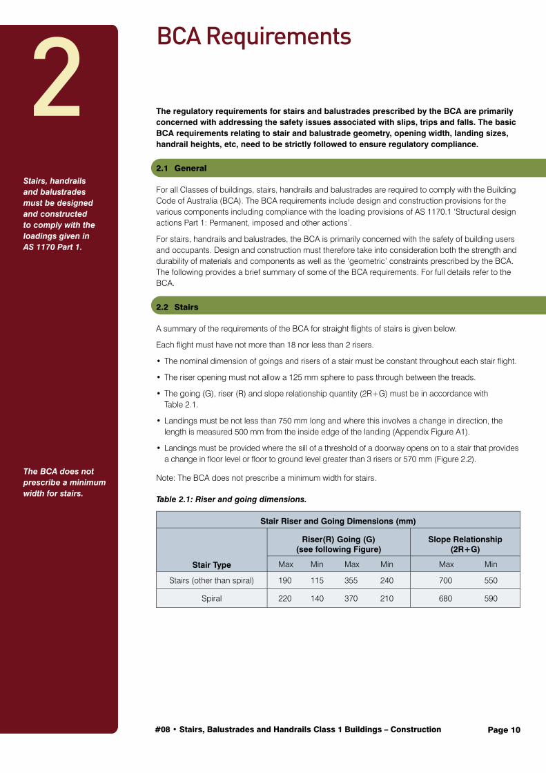
Table 2.1: Riser and going dimensions.
Stair Riser and Going Dimensions (mm)
Stair Type
Riser(R) Going (G)(see following Figure)
Slope Relationship(2R+G)
Max Min Max Min Max Min
Stairs (other than spiral) 190 115 355 240 700 550
Spiral 220 140 370 210 680 590
2Stairs, handrails and balustrades must be designed and constructed to comply with the loadings given in AS 1170 Part 1.
The BCA does not prescribe a minimum width for stairs.

Page 11#08 • Stairs, Balustrades and Handrails Class 1 Buildings - Construction
Figure 2.1: Landing length.
Figure 2.2: Threshold landings.
2.3 Balustrades and Handrails
A continuous balustrade or other barrier must be provided along the side of any roof to which public access is provided, any stairway or ramp, any floor, corridor, hallway, balcony, verandah, mezzanine, access bridge or the like and along the side of any path of access to a building, if it is not bounded by a wall; and any level is more than 1 m above the surface beneath (Figure 2.3).
The height of a balustrade or other barrier must be not less than 1 m above the floor of any access path, balcony, landing, etc, and not be less than 865 mm above the nosings of the stair treads or the floor of a ramp (Figure 2.4).

Page 12#08 • Stairs, Balustrades and Handrails Class 1 Buildings - Construction
Openings in balustrades (including decorative balustrades) or other barriers must be constructed so that any opening does not permit a 125 mm sphere to pass through it and for stairs, the space is tested above the nosing line (Figure 2.4).
For floors more than 4 m above the surface beneath, any horizontal elements within the balustrade or other barrier between 150 mm and 760 mm above the floor must not facilitate climbing.
Figure 2.3: Balustrades – when required.
Figure 2.4: Minimum handrail height.
Balustrades and handrails are required when stairs are not bounded by a wall and any level is more than 1 m above the surface beneath.

Page 13#08 • Stairs, Balustrades and Handrails Class 1 Buildings – Construction
Materials for External Stairs Without Riser Boards (Open Stairs)
The construction of stairs is very demanding and requires a high level of workmanship and accuracy. Open tread stairs are recommended for external use since housed risers will trap moisture and prevent good drainage and drying out. Housed treads can also trap moisture so pre-priming before assembly is highly recommended. As per the BCA requirements, the rise and going must be uniform throughout the flight, however for external stairs the bottom rise may vary slightly.
3.1 Timber Durability and Species
In weather-exposed, above-ground applications or where subjected to other sources of moisture, stringers, treads, risers, handrails, posts, newels, balusters, and infill should be:
(i) Warm, humid tropical northern climates: either Above Ground Durability Class 1 species with any sapwood present treated to H3 (or higher) or H3 (or higher) treated softwood such as Slash, Hoop or Radiata Pine. Preservative treatment to comply with AS 1604.
(ii) Temperate, cool southern climates: either Above Ground Durability Class 2 or better species with any sapwood present treated to H3 (or higher) or H3 (or higher) treated softwood such as Slash, Hoop or Radiata Pine. Preservative treatment shall comply with AS 1604. Lower durability species can also be utilised although careful detailing of joints with application and maintenance of protective coatings (paints, stains) and/or installation of protective shielding (e.g. malthoid) on top of exposed timber edges needs to be utilised.
Suitable species are given in Table 3.1.
Note:
1. Meranti, Victorian Ash, Tasmanian Oak and Douglas Fir are not suitable for weather exposed structural applications.
2. For harsh climates timber with a sawn upper face provides greater long term weathering ability than a dressed surface. Step treads exposed to the weather should therefore be sawn all round or sized on two edges and one face (underside) only.
3. In Queensland, timber species used in structural applications including stairs and balustrades shall comply with ‘Constructions Timbers in Queensland’ as referenced by the Building Code of Australia.
3

Page 14#08 • Stairs, Balustrades and Handrails Class 1 Buildings - Construction
Table 3.1: Suitable species.
Species AvailabilityPosts in ground contact
Posts not in ground, stringers, treads, landing framing and decking
Above Ground Durability Class 1
Preservative Treated Pine (Caribbean Hoop, Radiata, Slash)
All states 4 H5 Treatment 4 H3 Treatment
Mixed Open Forest Hardwoods (Qld, Nth NSW) Qld, NSW See Note 1 4
Blackbutt Qld, NSW See Note 1 4
Cypress All eastern states Sapwood Free 4
Gum Forest Red Qld 4 4
Gum Grey Qld, NSW 4 4
Gum River Red Vic, NSW See Note 1 4
Gum Spotted Qld, NSW, Vic See Note 1 4
Ironbark Red or Grey Qld, NSW, Vic 4 4
Jarrah WA, SA, Vic See Note 1 4
Kwila (Merbau) All states 4
Mahogany Red Qld, NSW See Note 1 4
Mahogany White Qld, NSW 4 4
Messmate Gympie Qld, NSW 4 4
Tallowwood Qld, NSW 4 4
Turpentine Qld, NSW 4 4
Above Ground Durability Class 2
Ash Silvertop Vic, NSW 4
Gum Southern Blue Vic, NSW 4
Gum Sydney Blue Vic, NSW 4
Gum Mountain Grey Vic, NSW 4
Jarrah WA, SA, Vic See Note 1 4
Kapur All states 4
Karri WA, SA, Vic 4
Mahogany Southern Vic, NSW 4
Stringybark Blue-Leaved NSW 4
Stringybark Yellow Vic, NSW 4
Notes:
1. These timbers should only be used for in-ground applications if they can be easily replaced if degrade occurs.
2. In Queensland, timber species used in structural applications including stairs, balustrades and handrails shall comply with ‘Constructions Timbers in Queensland’ as referenced by the Building Code of Australia.
Ensure timbers used for external stair construction have the required durability.

Page 15#08 • Stairs, Balustrades and Handrails Class 1 Buildings - Construction
3.2 Timber Grade
As stair stringers, treads and posts, etc, are structural members, they are required to be stress graded and should be free from any major strength-reducing features. In addition, timber for stair construction should also be straight grained and free from any imperfections that may detract from durability or serviceability performance requirements. Stringers, treads and posts should be in accordance with the following table.
Table 3.2: Timber grade.
Species Australian Standard Grade
Hardwood AS 2082 Structural Grade 1, Appearance grade
Softwood (Caribbean, Radiata, Slash and imported softwood)
AS 2858 Structural Grade 1, Appearance grade
Hoop Pine AS 2858 F8 Appearance grade
Cypress Pine AS 2858 F7 Appearance grade
Note: In addition, finger-jointed timber shall comply with AS 5068 – Timber – ‘Finger joints in structural products’ and laminated timber shall comply with AS 1328 – ‘Glued laminated structural timber’.
3.3 Moisture Content
Traditionally, timber used for external stair construction is unseasoned. Depending on location and species, the amount of shrinkage occurring in unseasoned timber will vary. Generally, about 6% shrinkage (6 mm per 100 mm) should be expected for unseasoned open forest hardwoods. Allowance should therefore be made for shrinkage in unseasoned stringers, treads and any associated newel posts, landing bearers and joists, etc, and for the gaps that will develop between joints such as between stringer housings and treads.
External stair timbers exposed to the weather will reach Equilibrium Moisture Content (EMC) with their surroundings after a period of 9-18 months, depending upon prevailing weather, size and type of timber used.
For coastal Australia, stairs that are well ventilated should reach an EMC of approximately 16%. For stairs close to and over water, EMCs will normally be a little higher (18-21%) and for dry inland areas considerably lower (10-12%).
Note: If seasoned timber is used for external stairs coastal areas, consideration must be given to the expansion of the timber as the EMC rises from 12% up to about 16%, particularly at joints – such as where treads are housed into stringers – and may cause splitting.
3.4 Joint Priming
One coat of a water-repellent preservative or an oil-based primer is recommended to be applied to joints and housings, etc, prior to fabrication.
3.5 Corrosion Protection of Fasteners
Having ensured that the maximum service life will be achieved in the timber component, it is equally important to match this with nails, screws, bolts and other metal connectors of equivalent service life. For most situations (up to and including close proximity to protected bays/mild marine) in exposed environments, hot dipped galvanised fasteners will afford the necessary protection from corrosion. The service life of hot dipped galvanised coatings will be proportional to their mass/area or thickness of galvanising and a minimum thickness of 42 microns is recommended for a service life of around 30 years. For more extreme corrosive environments or where other conditions dictate such as in contact with moist CCA/ACQ, etc, treated timber or in close proximity to swimming pools (within 600 mm of edge), guidance can be obtained from Table 3.3.
Structural members should be free of any major strength reducing features.
Allowance should therefore be made for shrinkage in unseasoned stringers, treads and any associated newel posts, landing bearers and joists, etc.
Except in severe environments, hot dipped galvanised fasteners will afford the necessary protection from corrosion.
Page 16#08 • Stairs, Balustrades and Handrails Class 1 Buildings - Construction
Table 3.3: Selecting corrosive resistant fasteners.
Application/Environment Fastener Material Remarks
Chemical, industrial and marine surf beach or large bays
Grade 316 stainless steel
Grade 304 stainless steel may require additional protective coatings such as epoxy paints.
Splash zone close to pools
Monel metal, silicon bronze and brass. Self drilling screws to be Class 4 finish.
Monel nails and screws available, usually used for boat building, are a good option close to pools. Silica bronze nails are good for acidic species such as western red cedar.
Mild marine, industrial and other
Hot dipped galvanised or mechanically plated, minimum thickness 42 microns. Self drilling screws to Class 3 finish.
Where hot dipped galvanised bolts, etc, are in contact with moist CCA/ACQ, etc, treated timber, additional protection using plastic sheaths, bituminous or epoxy paints is required.
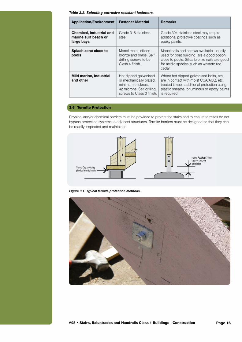
3.6 Termite Protection
Physical and/or chemical barriers must be provided to protect the stairs and to ensure termites do not bypass protection systems to adjacent structures. Termite barriers must be designed so that they can be readily inspected and maintained.
Figure 3.1: Typical termite protection methods.

Page 17#08 • Stairs, Balustrades and Handrails Class 1 Buildings - Construction
3.7 Slip Resistance
The BCA requires stair treads to have a slip resistant finish or an anti-skid strip near the nose of the tread. A number of proprietary ‘paints’ and ‘strips’ are available to satisfy this requirement.
3.8 Sizes
The sizes and spans for stringers and treads for external stairs shall be in accordance with Table 3.4 and 3.5.
Table 3.4: Stair stringers (maximum stair width 1800 mm).
Timber Type Stringer – [Depth (mm) x Thickness (mm )](1)
Species/Group Grade(2)200x38 200x50 250x38 250x50 300x50
Maximum Stringer Span (mm)(4)
Messmate, Spotted Gum, Blackbutt, Kwila, etc F27 2900 3200 3600 3900 4500
Vic Ash, Tas Oak, Jarrah F22 2800 3100 3400 3700 4300
Spotted Gum, Blackbutt, Ironbark, Kwila, etc F17(3) 2600 3000 3300 3600 4200
Douglas Fir (Nth American) F11 2400 2700 3000 3400 3900
Radiata, Hoop, Slash, etc F8 2300 2600 2900 3200 3700
H3 treated pine F5 1600 2200 2400 2800 3400
Notes:
1. The size of stringers given in the Table are nominal sizes. Design allowances have been made for dressing (depth 10 mm max, thickness 5 mm max). Allowance has also been made for trenching stringers to accommodate treads (10 mm max).
2. Timber grading should be in accordance with the appropriate Australian Standard for milled products (i.e. AS 2796 and AS 4785). The stress grades used for design in accordance with the loading requirements of the BCA are as indicated and can be determined for AS 2082 and AS 2858 as appropriate.
3. The F17 grade included in the Table is intended for unseasoned hardwood, to be used for external stairs only. 4. Stringer span is the centre line length of the stringer.
Table 3.5: Stair treads (with open flights).
Timber Type Stair Width [Tread span] (mm)
Species/Group Grade(2)750 1000 1200 1500 1800
Minimum Thickness of Tread (mm)(1)
Messmate, Spotted Gum, Blackbutt, Kwila, etc F27 26 32 38 48 58
Vic Ash, Tas Oak, Jarrah F22 28 34 40 50 60
Spotted Gum, Kwila, Ironbark, etc F17(3) 28 36 42 53 65
Douglas Fir (Nth American) F11 31 40 46 58 70
Radiata, Hoop, Slash, etc F8 32 42 50 62 73
H3 treated pine F5 40 46 54 70 N/A Notes:
1. The thicknesses in the Table are minimum design thicknesses and may not represent commercially available thicknesses.
2. Timber grading should be in accordance with the appropriate Australian Standard for milled products (ie AS 2796 and AS 4785). The stress grades used for design in accordance with the loading requirements of the BCA are as indicated and can be determined for AS 2082 and AS 2858 as appropriate.
3. The F17 grade included in the Table is intended for unseasoned hardwood, to be used for external stairs only.
Stringer span is the centre line length of the stringer

Page 18#08 • Stairs, Balustrades and Handrails Class 1 Buildings – Construction
Materials for Internal Stairs – With and Without Riser Boards (Open and Closed Stairs)Interior staircase work is considered to be a specialised section of carpentry and joinery. Flights are often prepared in a workshop making full use of available machines and equipment. Interior stairs differ considerably in design, from simple straight flights, commonly used in domestic work, to more elaborate stairs constructed purposely as an attractive feature in public and commercial buildings and in elegant homes.
Many interior stairs are built from joinery quality timber cut and seasoned specially for stairs. The specified finish is often clear polish/polyurethane, etc, therefore both material and workmanship should be of the very highest standard.
4.1 Timber Durability and Species
For internal use, timber of any durability class is suitable, however hardness may need to be considered for uncovered treads.
The species chosen will generally determine the overall colour of the stairs. As a guide, Table 4.1 indicates the range of colours that may be expected. The sapwood of many hardwoods can be much lighter than adjacent heartwood and some treads, risers, strings, etc, may contain both light and dark colours.
Lyctid susceptible sapwood of some hardwood species e.g. Spotted Gum is required by some state legislation, including Queensland and New South Wales, to be preservative treated. Some treatments may impart a brown or green-grey tinge to sapwood, while boron preservative is non-colouring. LOSP treatment is also used. In this instance a H3 treatment may be used in lieu of H2 treatment to avoid the colour from dyes often used with H2 LOSP treatments.
Hardness indicates a species resistance to indentation and abrasion. Damage to timber stairs may occur due to heavy foot traffic and in particular ‘stiletto-heel’ type loading. The selection of a hard timber species ensures improved resistance to indentation and abrasion. Soft timber species, if used for step treads, can be expected to indent.
Hardness may need to be considered for uncovered treads.
The selection of a hard timber species ensures improved resistance to indentation and abrasion.
4

Page 19#08 • Stairs, Balustrades and Handrails Class 1 Buildings - Construction
Table 4.1: Species guide.
Species Availability Colour Hardness
Australian Hardwood
Blackbutt Qld, NSW golden yellow to pale brown very hard
Brushbox Qld, NSW mid brown even colour hard
Forest Red Gum Qld, NSW dark brown or dark red brown very hard
Ironbark Qld, NSW, Vic dark brown or dark red brown very hard
Jarrah WA, SA, Vic dark red brown hard
Karri WA, SA rich reddish-browns to pale pinks hard
Manna/Ribbon Gum Vic pale straw pinks moderately hard
Messmate Vic pale yellow to pale brown moderately hard
New England Blackbutt Qld, NSW straw to pale brown very hard
Rose Gum Qld, NSW straw pink to light red hard
Southern Blue Gum NSW pale brown with some pink hard
Spotted Gum Qld, NSW brown, dark brown, light sapwood very hard
Stringybark Qld, NSW, Vic yellow brown with pink tinge hard
Sydney Blue Gum Qld, NSW pink to dark red hard
Tallowwood Qld, NSW pale straw to light brown hard
Tasmanian Oak All states pale straw to light brown, pink moderately hard
Victorian Ash All states pale straw to light brown, pink moderately hard
Imported Hardwood
Kwila / Merbau All states dark brown hard
Northern Box Qld, NSW mid brown even colour hard
Softwoods
Cypress All Eastern states straw sapwood, dark brown heartwood moderately hard
Hoop Pine (Araucaria) All states straw soft
Radiata All states white to straw soft
4.2 Timber Grade
As stair stringers, treads and posts, etc, are structural members, they are required to be stress graded and should be free from any major strength-reducing features. In addition, timber for stair construction should also be seasoned, straight grained and free from any imperfections that may detract from serviceability performance requirements. For internal stairs, stringers, treads and posts should be in accordance with AS 2796, AS 4785 and the following:
Table 4.2: Timber Grade
Type Australian Standard
Grade
Hardwood AS 2082 Structural Grade 1, seasoned, Appearance grade
Softwood (Caribbean, Radiata, Slash and imported softwood)
AS 2858 Structural Grade 1, seasoned, Appearance grade
Hoop Pine AS 2858 F7 seasoned, Appearance grade
Cypress Pine AS 2858 F7 seasoned, Appearance grade
Note: In addition, finger jointed timber shall comply with AS 5068 – Timber – ‘Finger joints in structural products’ and laminated timber shall comply with AS 1328 – ‘Glued laminated structural timber’.
Page 20#08 • Stairs, Balustrades and Handrails Class 1 Buildings - Construction
4.3 Moisture Content
Unless otherwise specified, all components of internal stairs should be seasoned. Seasoned timber is usually supplied at an average moisture content between 11% and 13%. Where conditions are drier or in air-conditioned buildings, moisture content of timber may vary from 7% to 12%. In these situations the timber may need to be acclimatised on-site prior to fabrication.
Timber is a natural product that responds to changes in weather conditions. During periods of high humidity timber will absorb moisture from the air causing it to swell or increase in size. Conversely, during drier times when humidities are low, timber will shrink, reducing in size. Unless the staircase is in a permanently controlled environment, the timber will always move in response to changing environmental conditions. Gaps between treads and housings, treads and riser boards, etc, can be expected as the timber accommodates seasonal changes. Additional shrinkage to that normally expected may also occur when a staircase is exposed to heat sources such as fireplaces or sunlight through large doors or windows.
A small amount of noise can be expected from most timber stairs when walked on. Noises can occur from movement of treads in housings, treads against a riser board or from treads, risers, etc, moving on nails.
4.4 Termite Protection
Because termite protection of the house is required under the BCA in areas where termites are present, there is no specific requirement for individual termite protection of internal stairs unless the only method of termite protection for the house is the use of termite resistant material. In this case, termite resistant timber should be also chosen for the stairs. Refer to AS 3660.1.
4.5 Slip Resistance
The BCA performance requirements state that stair treads or near the nosing shall be slip resistant. A number of proprietary ‘paints’ and ‘strips’ are available to satisfy this requirement.
4.6 Span Tables
The sizes and spans for stringers for internal stairs with and without riser boards shall be the same as for external stairs (Table 3.4).
Note: For internal stringers and treads, seasoned timber only should be used.
The size of treads for internal stairs without riser boards shall be the same as for external stairs (Table 3.5).
The size of treads for internal stairs fully supported by riser boards should be a minimum of 19 mm thick for stairs up to 1000 mm wide and 30 mm for 1000-1800 mm wide.
Note: For feature stairs, 30 mm is suggested as a minimum thickness for all treads irrespective of stair width.
For feature stairs, 30 mm is suggested as a minimum thickness for all treads, irrespective of stair width.
All components of internal stairs should be seasoned.
Unless the staircase is in a permanently controlled environment, the timber will always move in response to changing environmental conditions.

Page 21#08 • Stairs, Balustrades and Handrails Class 1 Buildings – Construction
Stair Construction Procedure
Before commencing the mark out for stairs, the calculations for going and rise can be determined (see Appendix B). From these, make a margin template and pitch board or set up a steel square with clamps ready to mark out strings.
5.1 Margin Template and Pitch Board
5.1.1 Pitch Board
Using a piece of plywood, masonite (such as ply or masonite bracing) or similar, mark out and cut a pitch board using the going and rise calculated (Figure 5.1).
Figure 5.1: Pitch board.
5.1.2 Margin Template
Before the margin template can be prepared, the width of the margin (X) must be known. The method of finding the margin width is as follows (Figure 5.2):
i) Place the pitch board on the string, with the hypotenuse of the pitch board flush with the string edge.
ii) Use off-cut pieces of tread and riser board to draw into this trial position, the tread, and also riser and wedges if used.
Note: For stairs with riser boards, place the off-cut piece of tread upside down and align the front edge of the riser housing with the edge of the string as shown in Figure 5.2.
iii) Draw a line just below the tread (or wedges if used) and parallel to the string edge.
iv) The distance X is the width required for the margin template.
Figure 5.2: Determination of margin line.
5

Page 22#08 • Stairs, Balustrades and Handrails Class 1 Buildings - Construction
A suitable margin template can now be constructed using off-cuts from mouldings (Figure 5.3).
Figure 5.3: Margin template.
Note: This method may be followed to determine the width of timber required for strings.
5.1.3 Steel Square
Any large metal square such as a roofing square can be used as an alternative to a pitch board and margin template, but an understanding of the proceeding methods is necessary to be able to set the square up correctly.
Use the steel square and metal stops to find the margin line as per 5.1.2 and Figure 5.4.
Figure 5.4: Using steel square to determine margin line.

Page 23#08 • Stairs, Balustrades and Handrails Class 1 Buildings - Construction
Reset metal stops on steel square incorporating margin line (Figure 5.5).
Figure 5.5: Using steel square as combined margin template and pitch board.
5.2 Marking Out Strings
When marking out stair strings a routine will prevent mistakes and the wasting of time. A good practice is to always mark out the same hand string first.
This practice should develop a clearer recognition of the correct positioning of members.
Note: The accepted practice of marking right hand or left hand string first varies from state to state and region to region. The procedure below is based upon marking the left hand string first.
Step 1The string handing is determined by looking up the flight or at the flight from the bottom. The string to the left is the left-hand string. The two strings in one flight are a pair; one left and one right-hand string.
Step 2Place strings in pairs on saw tools and mark inside face and top edges – consider the effect of any spring or bow. For short flights with one step bolt, place the hollow of the bow in and for longer flights with two step bolts place the hollow of the bow out. String edges should be rounds up (spring up) (Figure 5.6 ).
Figure 5.6: Pairing strings.
A good practice is to always mark out the same hand string first.

Page 24#08 • Stairs, Balustrades and Handrails Class 1 Buildings - Construction
Step 3Having paired the strings by face and edge marking them, commence marking out the left-hand string. Draw the margin line with the margin template, then using the pitch board, start at the bottom of the flight and mark the position of the floor, the first rise and going (Figure 5.6).
Before continuing to mark the string, a pair of wing dividers set to distance ‘H’ in Figure 5.6 should be used to mark along the margin line, the number of remaining steps in the flight. This action will serve to equalise successive marking with the pitch board and avoid possible loss or gain.
Step 4After completing the marking of the first string, place both strings together as a pair and square the points on the margin line across from one to the other. This method will prevent length differences between the two strings (Figure 5.7 and Figure 5.8).
Figure 5.7: Marking out left string.

Page 25#08 • Stairs, Balustrades and Handrails Class 1 Buildings - Construction
Figure 5.8: Marking out right string.
Step 5When satisfied that the initial marking, as in Figure 5.8, is correct, proceed to complete the marking for the housings. Number each tread and riser. Select treads and risers (if used) in numerical order and scribe thickness and shape onto strings. Using a gauge, mark the housing depth (15 mm) onto the back edge of the string. Always gauge from the outside of the tread. This will account for any differences in thickness of the tread particularly when using unseasoned rough sawn timber.
Note: Gauge depth = tread thickness minus housing depth (Figure 5.9).
Figure 5.9: String marked out for housings.
Gauge depth = tread thickness minus housing depth.

Page 26#08 • Stairs, Balustrades and Handrails Class 1 Buildings - Construction
5.3 Housing Strings
The actual housing out of the strings can be achieved by several different methods.
The simplest method, suitable for external stairs using rough sawn timber, is to use a power saw to cut along the lines marked for the treads.
Set the depth of the saw to the housing depth, 15 mm. Run the saw a number of times between these cuts and then use a mallet/hammer and chisel to remove the remaining material (Figures 5.10 and 5.11).
Figure 5.10: Housing strings.
A router with a template guide fitted can be used and is possibly the best and neatest method for housing strings on site (Figure 5.11).
Figure 5.11: Housing string practices.

Page 27#08 • Stairs, Balustrades and Handrails Class 1 Buildings - Construction
5.4 String End Joints
The marking for the appropriate joints at the ends of the strings can now also be completed.
The joint used will depend on the type of stair and the structure to which it is being attached. For example, for a simple external flight the string is generally notched over the bearer (or landing plate) or tenoned into a newel post at the top and birdsmouthed over the bottom tread (Figure 5.12).
Figure 5.12: Supporting stringers.
The joint used will depend on the type of stair and the structure it is being attached to.

Page 28#08 • Stairs, Balustrades and Handrails Class 1 Buildings - Construction
Where newel posts are used, tenons are cut on the end of the strings and the newels morticed to suit (Figures 5.13 and 5.14).
Figure 5.13: Tenons at ends of stringer.
In some cases (usually internal stairs only) the faces of the first and last risers should be in the centre of the newel posts.
Figure 5.14: Fixing strings to landing newels.
Stringers lift and separate!

Page 29#08 • Stairs, Balustrades and Handrails Class 1 Buildings - Construction
Cut treads and risers to length and number from bottom to top – make allowance for extra length on bottom tread if specified – remove arrises (edges) as required. If risers are being used and the treads are not pre-grooved, groove the treads for risers.
5.5 Step Bolts (Tie Bolts)
Unless the stairs fit between two walls, step bolts will be needed. Bore the stringers to take 12 mm step bolts at a maximum of 1350 mm centres. Position them to coincide as closely as possible to the centre line of the stringer and underside of a tread, leaving a gap between the underside of the tread and the bolt (Figure 5.15).
Figure 5.15: Position of step bolt.
Unless the stairs fit between two walls, step bolts will be needed.

Page 30#08 • Stairs, Balustrades and Handrails Class 1 Buildings - Construction
5.6 Assembly
Before starting to assemble external stairs, prime paint or oil all joints and surfaces that will be concealed, enclosed or unable to be painted after assembly including the newels, bearer or joist where the stairs are to be fixed.
A practical way to find the position of the stumps under the bottom tread – rather than by calculation – is to take one of the cut strings, place it in position and then level the tread housings with a spirit level (Figure 5.16). Make any adjustments necessary by packing under the lower end of the string. Use pilot pegs to locate the centre and top of the stumps as shown in Figure 5.16.
Figure 5.16: Finding position of stumps.
Fit top and bottom (or second bottom) treads and, for flights with risers, the bottom riser only to strings and nail together. Nail together with three 100 x 4.5 mm nails per joint. Pre-drill if necessary. For external stairs, all nails used should be hot dipped galvanised.
Fit and loosely tighten step bolts if required.
Lift this partly assembled job into position fit the stringers to the newels, bearers or joists as required.
Fit the remainder of the treads and risers where used and nail with three nails per housing.
Tighten the step bolts.
Note: When using unseasoned timber it is good practice to temporarily nail treads and risers. After allowing as much time as possible for shrinkage to take place, withdraw the nails, close the joints then complete nailing and punching.
When using unseasoned timber it is good practice to temporarily nail treads and risers. After allowing as much time as possible for shrinkage to take place, withdraw the nails, close the joints then complete nailing and punching.

Page 31#08 • Stairs, Balustrades and Handrails Class 1 Buildings – Construction
Balustrades and Handrails
For all Classes of building, balustrades and handrails are required to comply with the Building Code of Australia (BCA). The BCA requirements include design and construction provisions for the various components including compliance with the loading provisions of AS 1170.1 ‘Structural design actions Part 1: Permanent, imposed and other actions’.
For balustrades and handrails, the BCA is primarily concerned with the safety of building users and occupants. Design and construction must therefore take into consideration both the strength and durability of materials and components as well as the ‘geometric’ constraints.
See Section 2 for guidance on BCA requirements, including those for where the floor surface is more than 4 m above the floor/ground below.
6.1 Loads
AS 1170.1 requires balustrades and railings together with members and connections which provide structural support to be able to resist the following factored limit state loads – 0.9 kN inward, outward and downward load at any point. It also requires balustrades and handrails to be able to resist a factored horizontal or vertical load of 0.53 kN/m for all areas within or servicing exclusively one dwelling including stairs and landings excluding external balconies, and 1.13 kN/m for external balconies in domestic and other residential buildings. Infill, including balusters, should be capable of resisting 0.75 kN in any direction.
6.2 Materials
6.2.1 Durability
In weather-exposed, above-ground applications or where subjected to other sources of moisture, stringers, treads, risers, handrails, posts, newels, balusters and infill should be:
(i) Warm, humid tropical northern climates: either Above Ground Durability Class 1 species with any sapwood present treated to H3 (or higher) or H3 (or higher) treated softwood such as Slash, Hoop or Radiata Pine. Preservative treatment shall comply with AS 1604.
Balustrades and railings must resist 0.9 kN inward, outward and downward load at any point.
6
Use Above Ground Durability Class 1 or H3 treated pine species for weather exposed applications.

Page 32#08 • Stairs, Balustrades and Handrails Class 1 Buildings - Construction
(ii) Temperate, cool southern climates: either Above Ground Durability Class 2 or better species with any sapwood present treated to H3 (or higher) or H3 (or higher) treated softwood such as Slash, Hoop or Radiata Pine. Preservative treatment shall comply with AS 1604. Lower durability species can also be utilised although careful detailing of joints with application and maintenance of protective coatings (paints, stains) and/or installation of protective shielding (e.g. malthoid) on top of exposed timber edges needs to be utilised.
Suitable species are listed in Table 3.1.
Care should be taken to ensure that water is not trapped by end grain abutting horizontal surfaces (i.e. slope end grain cuts top and bottom of balusters and bottom rails where balusters abut, provide drainage holes, etc).
For internal use, timber of any durability class is suitable.
6.2.2 Timber Grade
The timber should be free from any major strength-reducing features, be straight grained and be in accordance with the following:
Table 6.1: Timber grade.
Type Australian Standard
Description Grade
Hardwood (Including Meranti) AS 2796 Sawn and milled
products Clear or select grade
Softwood (Including imported softwood) AS 1786
Joinery timber milled from Australian grown conifers
Clear grade
In addition, finger jointed timber shall comply with AS 5068 – Timber – ‘Finger joints in structural products’ and laminated timber shall comply with AS 1328 – ‘Glued laminated structural timber’.
Notes:1. Materials used in accordance with the following information must satisfy relevant Australian Standards and have the relevant minimum mechanical properties including the following:Hardwood – Stress Grade F22, (characteristic bending strength f’b = 65 MPa, Modulus of elasticity E = 16,000 MPa) and Joint Group JD2. Examples – Spotted Gum, Ironbark, Blackbutt, Kwila and Merbau.Meranti and Australian Softwood – (characteristic bending strength f’b = 25 MPa, Modulus of elasticity E = 9100 MPa) and Joint Group JD4. Examples – Radiata, Hoop and Slash Pine and Meranti.Imported Softwood – (characteristic bending strength f’b = 25 MPa, Modulus of elasticity E = 6,900 MPa) and Joint Group JD4. Examples – New Zealand Radiata Pine. 2. Unless certified by the supplier to identify that it is ‘Australian Grown’ softwood, handrail (balustrades) spans shall be determined from the ‘Imported Softwood’ spans given in Table 6.2.
6.3 Member Sizes
6.3.1 Handrails
Handrail sizes and spans shall be in accordance with Table 6.2.
6.3.2 Posts/Newel Posts
Posts and newel posts shall have a minimum stress grade of F5. Where supporting handrails/balustrades only, the minimum size of posts and newel posts shall be 80 x 80 mm (maximum post spacing 3600 mm and height of 2700 mm). Where supporting roof and or floor loads, refer to AS 1684 to determine minimum size, but shall be not less than 80 x 80 mm.
6.3.3 Infill/Balusters
The minimum size of infill/balusters should be as follows:
Hardwood – 19 x 19 mm or 21 mm diameter
Softwood – 19 x 42, 32 x 32 or 25 mm diameter.

Page 33#08 • Stairs, Balustrades and Handrails Class 1 Buildings - Construction
Table 6.2: Handrail sizes.
Timber Size/Description (mm x mm)
Maximum span of Handrail (mm)
Within or exclusivelyservicing one Dwelling(excluding external balconies)
Other areas in ResidentialBuildings (including external balconies)
Hardwood
65 x 65 (profiled) 3000 3000 3000 3000
42 x 65 (profiled) 2200 2700 2200 2700
42 x 85 (profiled) 2400 3400 2400 3400
35 x 70 2100 3000 2100 3000
35 x 90 2200 3600 2200 3600
35 x 120 2400 3600 2400 3600
45 x 70 2500 3200 2500 3200
45 x 90 2700 3600 2700 3600
45 x 120 2900 3600 2900 3600
70 x 70 3500 3500 3500 3500
70 x 90 3600 3600 3600 3600
Meranti and Australian Grown Softwood
65 x 65 (profiled) 2700 2700 2200 2200
42 x 65 (profiled) 1400 2000 1400 1800
42 x 85 (profiled) 1800 3000 1700 2400
35 x 70 1200 2400 1200 2000
35 x 90 1600 3200 1600 2500
35 x 120 2100 3600 1800 3400
45 x 70 2000 2800 1800 2200
45 x 90 2400 3400 2000 2900
45 x 120 2600 3600 2400 3600
70 x 70 3200 3200 2800 2800
70 x 90 3400 3600 3200 3600
Softwood Imported or Unknown Origin
65 x 65 (profiled) 2400 2400 2200 2200
42 x 65 (profiled) 1400 2000 1400 1800
42 x 85 (profiled) 1800 2700 1700 2400
35 x 70 1200 2400 1200 2000
35 x 90 1600 2900 1600 2500
35 x 120 1900 3600 1800 3400
45 x 70 2000 2600 1800 2200
45 x 90 2200 3100 2000 2900
45 x 120 2300 3600 2300 3600
70 x 70 2900 2900 2800 2800
70 x 90 3000 3400 3000 3400
Notes:
1. Handrails with no intermediate vertical supports may be used on flat or on edge (Figure 6.2).
2. Handrails with intermediate vertical supports shall be installed on flat with intermediate vertical supports spaced not greater than the allowable spans given for the same handrail with no intermediate vertical supports (Figure 6.2 and Note: For Type E connections refer to manufacturers’ specifications).
3. Figure 6.4.
4. Where a top rail (minimum size 42 x 65) is within 150 mm of the main handrail and is rigidly fixed to it (using blocks, or balusters or dowels that pass through the mid rail and are fixed to the top rail) at least once at mid span, the allowable span of the handrail may be increased by 300 mm.
5. Handrail spans have been limited to 3600 mm maximum.
6. Profiled sections typically include bread loaf, ladies waist and colonial profiles.
7. There is no negative tolerance permitted on the breadth or depth dimensions (overall outside dimensions of profiled shapes) given in the above Table.

Page 34#08 • Stairs, Balustrades and Handrails Class 1 Buildings - Construction
Figure 6.1: Intermediate vertical support.
Figure 6.2: Handrails – on flat and on edge.

Page 35#08 • Stairs, Balustrades and Handrails Class 1 Buildings - Construction
6.4 Connections
6.4.1 Posts
Posts and newel posts should be connected to floor framing/stringers in accordance with Figure 6.3.
Figure 6.3 (a): Posts and newel posts.
Figure 6.3(b)

Page 36#08 • Stairs, Balustrades and Handrails Class 1 Buildings - Construction
Figure 6.3(c)
6.4.2 Handrails
Table 6.3: Loads on handrails.
Span Type
Handrail Span (mm)
Handrail Connection Loads (kN) Example Of DeterminingHandrail Connection
Within or exclusively servicing one Dwelling (exc.external balconies)
Other Areas in Residential Buildings (inc.external balconies)
Single Span
1800 0.90 1.0The shaded areas in Tables 6-3 and 6-4 provide a guide to the selection of an appropriate connection for a continuous span softwood handrail span of 2400 mm.
Step 1. From Table 6-3 determine the load on the handrail = 2.7 kN
Step 2 From Table 6.4 and Figure 6.4, determine a connection with the capacity to resist 2.7 kN.
Step 3 Acceptable solutions determined from Table 6-4 are:-
Type A connection, 1 M10 bolt or Type B connection, 2 No 10 screws or Type D connection, 2 No 10 screws per leg of bracket.
2100 0.90 1.2
2400 0.90 1.4
2700 0.90 1.5
3000 0.90 1.7
3300 0.99 1.9
3600 1.1 2.0
Continuous Span
1800 1.1 2.0
2100 1.3 2.4
2400 1.4 2.7
2700 1.6 3.0
3000 1.8 3.4
3300 2.0 3.7
3600 2.2 4.1

Page 37#08 • Stairs, Balustrades and Handrails Class 1 Buildings - Construction
Table 6.4: Capacity of handrail connections.
Timber Capacity of Connections (kN)
Type A Type B Type C Type D
No. Bolts
Bolt Size (Cuphead)
No. Screws
Screw Size (Type 17)
Screws Nails 2 / Screws per leg of bracket
M10 M12 No10 No14 2/ No10
2/No14
2/3.15 dia
2/3.75 dia
No10 No14
Hardwood(JD2)
1 13 14 1 3.4 4.4 1.9 2.3 1.6 1.8 4.9 7.6
2 26 28 2 6.8 8.8
Softwood and Meranti (JD4)
1 8 9 1 2.0 2.6 1.1 1.3 0.9 1.0 2.8 4.3
2 16 18 2 4.0 5.2
Notes: 1. For Type A connections quantities are given for both face mounted handrails (worst case) and handrails flush full or half checked to post. 2. For Type B connections, minimum screw penetration into post is 38 mm and handrails flush full or half checked to post. 3. For Type C connections the minimum screw penetration into post is 40 mm and the minimum nail penetration into post is 38 mm. 4. Midrails and bottom rails shall be fixed with a minimum of 2/3.15 dia. skew nails.
Figure 6.4: Handrail connections. Note: For Type E connections refer to manufacturers’ specifications.

Page 38#08 • Stairs, Balustrades and Handrails Class 1 Buildings - Construction
Weathering, Finishes and Maintenance
The long-term durability and visual appeal and aesthetics of both internal and external stairs and balustrades can be greatly enhanced by application and maintenance of suitable and appropriate finishes.
7.1 External Stairs and Balustrades
Other than for aesthetic reasons, the main objective of applying and maintaining finishes (paints and stains) on timber used in external applications is to minimise the effects of weathering and therefore to maximise the service life of the timber. Exposure to sun and rain leads to wetting and drying and subsequent checking, splitting and distortion.
Application and maintenance of finishes should not be considered as a substitute for ensuring that the inherent durability (natural or by treatment) of the underlying timber is appropriate to the service life required for the applicable hazard level.
7.1.1 Unprimed Timber
Nail holes should be stopped with an exterior grade wood filler. Dirt or any loose material should be removed prior to coating. All surfaces, ends and joints should be primed prior to assembly with a quality solvent-based alkyd primer or stain, in accordance with the manufacturers’ recommendations.
Final top coats of exterior paint or stain should then be applied in accordance with the manufacturers’ recommendations.
7.1.2 Pre-primed LOSP Treated Timber
Pink pre-coated handrail and balustrade components should be sanded back and dusted off to remove any loose or powdery coatings prior to finishing. Nail holes should be stopped with an exterior grade wood filler.
All surfaces, ends and joints should be primed prior to assembly with a quality, solvent based alkyd primer. When the primer has dried in accordance with the manufacturers recommendations, apply two full coats of premium 100% acrylic exterior topcoat in accordance with manufacturers recommendations.
Dark coloured paints and stains should be avoided as they heat timber to elevated temperatures which cause greater loss of moisture and subsequent shrinkage and checking. Decay is also more active at higher temperatures.
7.2 Internal Stairs
The finish for interior stairs is often clear polish, lacquer, etc, therefore both material and workmanship should be of the very highest standard.
If clear finishes are to be used, extra care should be taken when marking out that pencil marks, etc, are kept light and do not leave an indentation in the timber.
Any nails should be punched a minimum of 3 mm below the surface of the boards. The punched nail holes can then be filled with either oil or non-oil based filler. Oil-based fillers may bleed oil into the timber and affect the colour of the wood surrounding the nail hole, or may not be compatible with various coating products.
The colour of the filler should be carefully selected to minimise any visual impact of the filler. Many of these products are sold in colours pre-matched to specific species. Generally all fillers are slightly darker and this allows for the boards to deepen in colour following finishing and UV exposure.
Application and maintenance of finishes should not be considered as a substitute for ensuring that the inherent durability of the underlying timber is appropriate to the service life required.
7

Page 39#08 • Stairs, Balustrades and Handrails Class 1 Buildings - Construction
Table 7.1: Clear finishes for stairs.
Oil based Alkyds Composite Solvent based Water based
Tungoil
Linseedoil based varnishes
Oil modifiedUrethanes (OMU)
Urethaneoil/alkyd ‘Tung oil’
2 pack Single pack Polyurethane
Polyurethane Polyurethane (moisture cured)
Acrylic Single and two pack
Less wear resistant finish requiring more frequent maintenance
High wear resistant finish Moderate to high wear resistant finishes
6-24 hour drying by solvent evaporation 1-4 hour drying by chemical reaction
2-4 hour drying by evaporation and reaction
Some tolerance to waxes Not tolerant to waxes Not tolerant to waxes
Moderate to strong odour on application Strong odour on application Minimal odour on application
Avoid inhalation and contact Avoid inhalation and contact Avoid inhaling cross-linkers and hardeners
Matt to gloss levels Matt to very high gloss levels Matt to gloss levels
Darkens with age Darkens with age Less darkening with age
Generally ready for use 2-5 days from completion*
Generally ready for use 2-3 days from completion*
Generally ready for use 2 days from completion*
*Varies with weather conditions and product. Full curing may take a longer time.
Generally all fillers are slightly darker and this allows for the boards to deepen in colour following finishing and UV exposure.

Page 40#08 • Stairs, Balustrades and Handrails Class 1 Buildings - Construction
Appendix A – Glossary
Refer to Figures A1 and A2 for illustrations of most terms.
A1 General
Stair, Stairs: An assembly of steps or flights including all necessary landings, balustrades, etc, constructed for the easy, convenient and safe passage from one floor to another.
Staircase: Means the same as stair or stairs but includes that part of the building enclosing the stairs.
Stairway: Generally means the space provided for the stairs including the opening in the floor.
Stairwell or well hole (the opening in the upper floor for the stairs): The vertical space seen down between the outer strings of stairs having one or more return flights.
Step: A combination of a tread and riser. One unit in stairs.
Flight: That portion of stairs that has a continuous series of risers, including risers of winders, not interrupted by a landing or floor.
Riser: The height between consecutive treads (top of tread to top of next tread).
Total rise (Rise of flight, Rise of stair): The vertical measurement from the top of the first (lowest) floor or ground to the top of the last (highest) floor regardless of the number of flights in the stair.
Going: The horizontal dimension from the front to the back of a tread less any overhang from the next tread above (front of a riser line to front of the next riser line).
Total going (Going of flight, Going of stair): The horizontal distance measured in one direction over one or more flights, including intermediate landings, and taken from the front edge of the first or bottom tread in the lower flight to the front edge of the floor or landing at the top of the stairs. Again, if risers are fitted, the horizontal measurement from the face of the first or lowest riser to the face of the last or top riser in the stairs.
Stair width: The unobstructed width measurement between the inside face of the handrails, or the stringers if there are no handrails. (Note: The BCA does not prescribe a minimum width for stairs.)
A2 Members in a Staircase
String, stringers or string boards (sides of the stair): The inclined members in a stair which usually act as a beam and which span from bottom to top of each flight and support the ends of the treads and risers.
Treads: The horizontal members in a flight on which the foot is placed when ascending or descending the flight.
Step bolt (tie bolt): A horizontal threaded rod commonly used to tie the stringers together in external open flight stairs.
Riser boards: The vertical boards fixed between successive treads. Their purpose is to close the openings between and help to support and stiffen the treads.
Nosing: The front edge of a tread that may or may not be projecting over the riser. It is usually rounded.
Scotia: A small moulding having a concave face. It may be fitted against the top face of the riser and under the nosing of some boxed stairs (rarely used these days).
Newels: The posts at the top and bottom of flights to which strings and balustrades are fixed. Newels may also support landings and form part of balustrades.
Landing: An area (floor or resting place) at the top or bottom of a flight or between two flights.
A

Page 41#08 • Stairs, Balustrades and Handrails Class 1 Buildings - Construction
A3 Members in a Balustrade
Balustrade: A coping or handrail with supporting balusters. An open balustrade comprises balusters, handrail, bottom rail or string capping. A solid balustrade may have panelling, glass or perspex instead of balusters.
Balusters: Vertical members which infill the space beneath and support the handrail.
Handrail: The support for the hands at the side of the stairs or landings/decks, etc.
Bottom rail (string): The lowest horizontal member in a balustrade that supports the balusters.
Mid rail: A rail parallel to and between a handrail and bottom rail or string.
Handrail support: A vertical piece of timber fixed between the string and handrail to strengthen the handrail and mid rail.
String capping: A timber member fixed to the top edge of the string to receive the balusters.
False tenon: A piece of hardwood inserted into a mortice in the newel post and a mortice or groove in the handrail and nailed in position. This type of joint allows easy assembly of rails to newel posts.
A4 Construction Terms
Going rod: A rod on which is marked the going of each step, the going and the position of the landings i.e. the length of the flight.
Height rod: (storey rod) A rod on which is marked the rise of flights and the rise of each tread.
Pitch board: A triangular template, usually made of galvanised iron or plywood, one of its sides equal to the going, a side at right angles to the going equal to the riser. (A roof square plus fence would be an alternative).
Margin line: A line marked on the inside face of the string 38 to 50 mm parallel to the top edge. From this line the housings are usually positioned.
Margin template: A gauge used against the top edge of the string to mark the margin line. It is used in conjunction with the pitch board to mark out the locations of the treads and risers.
Line of nosing or nosing line: A line touching the front top edge of all the treads, landing and/or floor. It is a separate line to the margin line when the nosing of the tread projects in front of the face of the riser board.
Landing joist: A beam that runs between landing trimmers to support the flooring or decking.
Landing trimmer: A beam at the front of a landing which supports the landing joists, newel posts and top of each flight.
Undercarriage or carriage piece: An additional heavy timber support system fitted beneath wide stairs.
Spandrel framing: Vertical framing and panels which may infill the triangular space between the underside of the outer string and the floor.
Stair soffit: Plywood or plasterboard lining, etc, used to cover the underside of the stairs.

Page 42#08 • Stairs, Balustrades and Handrails Class 1 Buildings – Construction
Figure A1: Terminology – Stairs and landings.
Figure A2: Terminology – Balastrades and handrails.

Page 43#08 • Stairs, Balustrades and Handrails Class 1 Buildings – Construction
Appendix B – Stair Calculations
B1 General
To obtain the facts required to be able to set out, order material and build stairs, some detailed measuring and calculating is necessary.
To suit the stock width of material available, stairs are usually built with a 240 to 250 mm going and a rise from 160 to 180 mm. See Section 2.
The rise can only be calculated from the total rise. The total rise should be measured with a tape from the lower floor level to the upper floor level. The total rise found may now be applied to a calculation (see B2).
To determine the total rise for external stairs where the ground is not level and either slopes toward or away from the building, refer to Appendix C.
The following problems are examples of how to find the unknown such as rise, going, number of rises and goings from the known facts, i.e. total rise and as in some cases the restricted space available for the total going of a stair as well as headroom.
B

Page 44#08 • Stairs, Balustrades and Handrails Class 1 Buildings - Construction
B2 Example 1
Straight flight of external stairs with the total rise = 2665 mm. The total going is unrestricted and the proposed treads will be 250 x 38 mm unseasoned hardwood.
Calculate rise:Divide the rise of the flight by a trial rise of 170 mm (for external stairs the rise is generally about 180 mm and for internal about 175 mm) to obtain the approximate number of rises.
2665÷170 mm = 15.67. This gives 15 risers at 170 mm and one at 115 mm. (2665 – (170 x 15))
Although it is allowable to have a different rise at the bottom of external stairs, this should be avoided where possible, so round off to the nearest whole number = 15.
Rise = (2665÷15) = 177 mm
Note: The result of the above calculation is 177.66 but we can round down up or down to the nearest whole number. If rounded down, the result is that the rise of the flight will be 10 mm less than the total rise of 2665. However, when the stairs are built to this and put in place, the treads will have a slight slope to the front, in this case just less than 1 mm per tread. This is acceptable and for external stairs can assist water to run off the treads.
Calculate going:The tread width is 250 mm so this can be our going. (Where an overhang on the tread is provided, the going will need to be adjusted accordingly.)
Calculate total going:There is always one less tread than the number of risers so the going of the flight will be: 250 mm (the tread width) x 14 (15 risers - 1) = 3500 mm.
Check results with BCA requirements:
Rise: 177 mm is within the range of 115 to 190 mm.
Going: 250 mm is within the range of 240 to 355 mm.
Slope relationship: 177 x 2 + 250 (rise multiplied by 2 + the going) = 604 is within the range of 700 to 550 mm.
Another requirement of the BCA, that a 125 mm sphere must not pass through treads, should also be checked. The rise, 177 mm, less the tread thickness, 38 mm, must be less than 125 mm. 177 – 38 = 137. This is more than 125 and so is not within the BCA requirement. A cleat could be fixed under the tread above to close up the space to comply.
Figure B1
Page 45#08 • Stairs, Balustrades and Handrails Class 1 Buildings - Construction
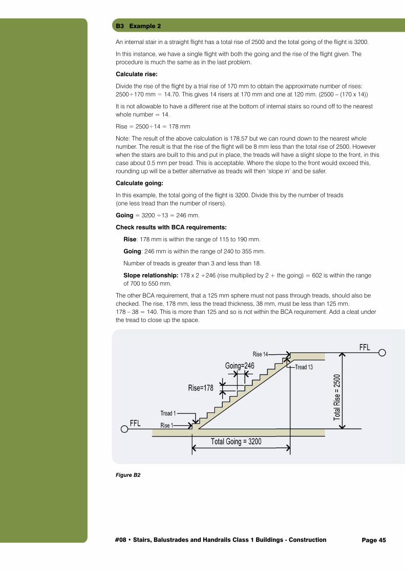
B3 Example 2
An internal stair in a straight flight has a total rise of 2500 and the total going of the flight is 3200.
In this instance, we have a single flight with both the going and the rise of the flight given. The procedure is much the same as in the last problem.
Calculate rise:
Divide the rise of the flight by a trial rise of 170 mm to obtain the approximate number of rises: 2500÷170 mm = 14.70. This gives 14 risers at 170 mm and one at 120 mm. (2500 – (170 x 14))
It is not allowable to have a different rise at the bottom of internal stairs so round off to the nearest whole number = 14.
Rise = 2500÷14 = 178 mm
Note: The result of the above calculation is 178.57 but we can round down to the nearest whole number. The result is that the rise of the flight will be 8 mm less than the total rise of 2500. However when the stairs are built to this and put in place, the treads will have a slight slope to the front, in this case about 0.5 mm per tread. This is acceptable. Where the slope to the front would exceed this, rounding up will be a better alternative as treads will then ‘slope in’ and be safer.
Calculate going:
In this example, the total going of the flight is 3200. Divide this by the number of treads (one less tread than the number of risers).
Going = 3200 ÷13 = 246 mm.
Check results with BCA requirements:
Rise: 178 mm is within the range of 115 to 190 mm.
Going: 246 mm is within the range of 240 to 355 mm.
Number of treads is greater than 3 and less than 18.
Slope relationship: 178 x 2 +246 (rise multiplied by 2 + the going) = 602 is within the range of 700 to 550 mm.
The other BCA requirement, that a 125 mm sphere must not pass through treads, should also be checked. The rise, 178 mm, less the tread thickness, 38 mm, must be less than 125 mm. 178 – 38 = 140. This is more than 125 and so is not within the BCA requirement. Add a cleat under the tread to close up the space.
Figure B2

Page 46#08 • Stairs, Balustrades and Handrails Class 1 Buildings - Construction
B4 Example 3
Straight flight of external stairs with the total rise = 3600 mm. The total going is unrestricted and the proposed treads will be 250 x 50 mm unseasoned hardwood.
Calculate rise:Divide the rise of the flight by a trial rise of 170 mm (170 is an average rise for stairs) to obtain the approximate number of rises.
3600 ÷170 mm = 21.17 – rounded off to the nearest whole number = 21.
Rise = 3600 ÷ 21 = 171 mm (Rounded down as per the above examples)
However, the number of risers exceeds that allowed by the BCA in a single flight (not more than 18) so a landing will need to be incorporated.
Calculate going:
The tread width is 250 mm so this can be our Going.
Calculate total going:
Flight 1 – 250 mm = 9 x 250 = 2250 mm plus Flight 2 – 250 mm = 10 x 250 = 2500 mm plus the landing width 900 mm = 5650 mm.
Check results with BCA requirements:
Rise: 171 mm is within the range of 115 to 190 mm.
Going: 250 mm is within the range of 240 to 355 mm
We have already established the number of treads is greater than 18 and a landing needs to be incorporated.
Slope Relationship: 171 x 2 +250 (rise multiplied by 2 + the going) = 592, within the range of 550 to 700 mm.
The other BCA requirement, that a 125 mm sphere must not pass through treads, should also be checked. The rise, 171 mm, less the tread thickness, 50 mm, must be less than 125 mm. 171 – 50 = 121. This is less than 125 and so is within the BCA requirement.
Figure B3
Slope relationship calculations:
The calculations to determine the slope relationship in the above examples worked out to be within the BCA requirement.
If the going plus twice the rise worked out to less than 550 this would indicate that the step was too small and the solution would be to leave out one step and do the calculation all over again.
If, on the other hand, the first trial rise and going caused the step to be too large (i.e. if the going plus twice the rise worked out to larger than 700) the solution would be to add another step.

Page 47#08 • Stairs, Balustrades and Handrails Class 1 Buildings - Construction
B5 Headroom for Stairs
Headroom or head way: Provision should always be made for sufficient height so that the head of anyone will not strike against the edge of the landing or soffit above. This vertical height or space is called ‘headroom’ and it should not be less than 2000 mm. (The BCA minimum is 2000 mm, but 2100 mm is preferred).
The headroom in the stair shown in Figure B4 would be found by taking the number of risers contained within the opening of the floor (14), multiplying it by the rise and subtracting the depth of the floor. Note also that the length of the opening has the same number of treads (14) as there are risers in the headroom.
Assuming the stair in Figure B4 to have a rise of 177 mm and the depth of the floor 260 mm, the method of finding the headroom would be:
Rise x number of risers in the headroom portion of the stair minus the depth of the floor.
Headroom = 177 x 14 – 260 = 2478 – 260 = 2218 mm
Figure B4
For stairs in two flights, the method of finding the headroom is obtained by studying Figure B5. Note that the headroom is taken from the underside of the ceiling, at the corner of the trimmer, vertically down to the nosing line.
Count the risers from the top of the stairs down to the lower arrow point marking the headroom. There are 8 risers from the top of the stair to the top of the landing, and from the top of the landing to the top of the tread (indicated by the arrow point) there are 7 risers (one less than in the upper flight) making 15 in all.
Assuming a rise of 156 mm, take the height of these 15 risers:
156 x 15 = 2340
Now subtract the thickness of the 225 mm upper floor:
= 2340 – 225 – Headroom = 2115 mm
In other words, to find the headroom double the number of risers in the upper flight, subtract one, multiply by the rise then subtract the thickness of the upper floor (Figure B5). Apart from the flight shown in Figure B5, this applies to any flight with a landing including a straight stair, dog-leg flight, etc.
The BCA minimum is 2000 mm, but 2100 mm is preferred.

Page 48#08 • Stairs, Balustrades and Handrails Class 1 Buildings - Construction
This may be written as a formula as: Headroom R x (U x 2 – 1) – T, where:
R = riseU = number of risers In upper flightT = thickness of upper floor
The previous example can be calculated thus:Headroom = R x (U x 2 – 1) – T= 156 x (8 x 2 – 1) – 225= 156 x 1.5 – 225= 2340 – 225= 2115
Figure B5
Note: A study of Figure B6 will show clearly the affect on headroom by taking one rise from the top flight and so adding one to the bottom flight; the result is a reduced headroom by two rises (e.g. 2115 mm – (156 x 2) = headroom of 1803 mm which would not be suitable).
Figure B6

Page 49#08 • Stairs, Balustrades and Handrails Class 1 Buildings - Construction
B6 Practical Method for Calculating Number of Rises and the Rise
After marking the total rise onto a storey rod, a pair of carpenter’s wing dividers should be set to a trial rise (165 to 170 mm) and then stepped along the storey rod to finish within the total rise. While doing this, the number of spaces should be counted and recorded (Figure B7).
Figure B7
The distance between the last divider mark and the total rise mark on the storey rod (X) is now divided by the number of spaces counted and the result added to the first setting of the dividers.
If X = 60 mm then 60÷12 = 5 Trial rise 170 mm + 5 mm Rise = 175 mm
Restep the dividers along the storey rod as a check, but now the last step should finish exactly on the total rise mark and the number of spaces or rises should be as before (Figure B8).
Figure B8You should now have the number of rises and the exact rise and consequently the number of goings which is always one less than the number of rises. Remember that a landing is counted as a going so that when a landing is required in a stair there will be two flights and the number of treads in both flights will be two less than the total number of rises in the stair.
B7 Quantity Calculations
B7.1 String Length Required
This is normally determined by measurement from a full size set out of a section through the flight, showing the treatment of the string at both ends; however for ordering purposes, application of the rule ‘number of treads in the flight x 300 mm + 500 mm’ should provide sufficient material.
Note: The 500 mm allows for variations of treatment at top and bottom of the string.
Using Example 1 above:
No. of treads in the flight x 300 mm + 500 mm15 x 300 mm + 500 mm4500 mm + 500 mmString length = 5000 mm Two strings of 5000 mm are required. (i.e. order 2 of 5.1 m)

Page 50#08 • Stairs, Balustrades and Handrails Class 1 Buildings - Construction
B7.2 Number of Treads
From the previous calculations in Examples 1, 2 and 3, the number of treads is known. The length of each tread will depend on the width of the stairs.
Using Example 1 above and width of flight = 900 mm:
No. of treads in the flight = 15Tread length = 900 mm15 treads @ 900 mm.
If these are ordered as 15 individual pieces, this does not allow very much margin for error or any end splits that may need to be cut off. Ordering 5 pieces 3000 mm long will allow a suitable amount without being uneconomical.
B7.3 Tread Cutting Length
The cutting length of a tread will be the overall width of the stair minus twice the gauge depth (Figure B9).
Example:
Width of stair = 900 mmHousing depth = 15 mmString thickness = 50 mm
Tread cutting length = 900 – (2 x (50 – 15)) = 900 – 70= 830 mm
Figure B9: Tread cutting length.

Page 51#08 • Stairs, Balustrades and Handrails Class 1 Buildings - Construction
Appendix C – Total Rise Calculations – Sloping Ground
C1 Determining Total Rise on Sloping Ground
The following guidance can be used to determine the total rise for external stairs where the ground is not level and either slopes toward or away from the building.
Note: These methods have generally been replaced by the use of laser levels, etc.
Figure C1: Stairs without landing – Land sloping towards building.
These methods have generally been replaced by the use of laser levels, etc.
C

Page 52#08 • Stairs, Balustrades and Handrails Class 1 Buildings - Construction
Figure C2: Stairs with landing – Land sloping towards building.
Figure C3: Stairs without landing – Land sloping away from building.Note: this situation to be avoided wherever possible as it adds to the number of treads required.

Page 53#08 • Stairs, Balustrades and Handrails Class 1 Buildings - Construction
Figure C4: Stairs with landing – Land sloping away from building.Note: this situation to be avoided wherver possible as it adds to the number of treads required.