070 – NORWEGIAN OIL AND GAS APPLICATION OF IN THE ...
237
070 – NORWEGIAN OIL AND GAS APPLICATION OF IEC 61508 AND IEC 61511 IN THE NORWEGIAN PETROLEUM INDUSTRY (Recommended SIL requirements)
Transcript of 070 – NORWEGIAN OIL AND GAS APPLICATION OF IN THE ...
070 – NORWEGIAN OIL AND GAS
APPLICATION OF IEC 61508 AND IEC 61511
IN THE NORWEGIAN PETROLEUM INDUSTRY
(Recommended SIL requirements)

Norwegian Oil and Gas Association Application of IEC 61508 and IEC 61511 in the Norwegian Petroleum Industry (Recommended SIL requirements) No.: 070 Established: February 2001 Revision no.: 03 Date revised: June 2018
2 of 237
Table of content FOREWORD ............................................................................................................................................................ 4
1 INTRODUCTION............................................................................................................................................. 5 1.1 SCOPE AND PURPOSE OF GUIDELINE .......................................................................................................... 5 1.2 CONTENT OF GUIDELINE ........................................................................................................................... 5 1.3 CHANGES FROM PREVIOUS VERSION OF THIS GUIDELINE ............................................................................ 6
2 THE IEC 61508 AND IEC 61511 STANDARDS ............................................................................................. 8
3 REFERENCES ............................................................................................................................................... 11
4 DEFINITIONS AND ABBREVIATIONS ..................................................................................................... 13 4.1 DEFINITIONS .......................................................................................................................................... 13 4.2 ABBREVIATIONS ..................................................................................................................................... 14
5 MANAGEMENT OF FUNCTIONAL SAFETY ........................................................................................... 18
5.1 OBJECTIVE ............................................................................................................................................. 18 5.2 RISK REDUCTION, BARRIER MANAGEMENT AND MANAGEMENT OF FUNCTIONAL SAFETY .......................... 18 5.3 COMPETENCE REQUIREMENTS ................................................................................................................ 19
5.3.1 SIS design .......................................................................................................................................... 19 5.3.2 SIS follow-up during operation .......................................................................................................... 19
5.4 SAFETY PLANNING ................................................................................................................................. 20 5.5 FUNCTION SAFETY AUDITS AND REVISIONS ............................................................................................. 20 5.6 VERIFICATION ........................................................................................................................................ 21 5.7 VALIDATION .......................................................................................................................................... 21
6 FUNCTIONAL SAFETY ASSESSMENT ..................................................................................................... 22
6.1 OBJECTIVE ............................................................................................................................................. 22 6.2 FSA EXECUTION .................................................................................................................................... 22
7 DETERMINING SIL REQUIREMENTS ..................................................................................................... 24 7.1 OBJECTIVE ............................................................................................................................................. 24 7.2 APPROACH ............................................................................................................................................. 24 7.3 HAZARD AND RISK ANALYSIS ................................................................................................................. 26
7.3.1 Scope of hazard and risk analysis ...................................................................................................... 26 7.3.2 Process Hazard Analysis (PHA) ........................................................................................................ 26
7.4 DEFINITION OF SAFETY INSTRUMENTED FUNCTIONS AND SIL ALLOCATION.............................................. 27 7.5 MINIMUM SIL REQUIREMENTS ............................................................................................................... 28 7.6 HANDLING OF DEVIATIONS FROM THE MINIMUM SIL REQUIREMENTS ...................................................... 37
7.6.1 Identification of deviations from the minimum SIL table .................................................................... 37 7.6.2 Determination of SIL for safety functions where section 7.5 is not applicable .................................... 37
7.7 SAFETY REQUIREMENTS SPECIFICATION ................................................................................................. 38
8 SIS DESIGN AND ENGINEERING .............................................................................................................. 39 8.1 OBJECTIVES ........................................................................................................................................... 39 8.2 INPUT ..................................................................................................................................................... 39 8.3 SIL REQUIREMENTS ............................................................................................................................... 39
8.3.1 Quantitative requirements ................................................................................................................. 39 8.3.2 Architectural constraints ................................................................................................................... 40 8.3.3 Avoidance and control of systematic faults ........................................................................................ 41
8.4 PROVEN IN USE AND PRIOR USE .............................................................................................................. 42 8.4.1 Proven in use ..................................................................................................................................... 42 8.4.2 Prior use ........................................................................................................................................... 42
8.5 REQUIREMENTS TO FAILURE DATA ......................................................................................................... 43 8.5.1 Objective ........................................................................................................................................... 43 8.5.2 SIS data sources ................................................................................................................................ 43
Norwegian Oil and Gas Association Application of IEC 61508 and IEC 61511 in the Norwegian Petroleum Industry (Recommended SIL requirements) No.: 070 Established: February 2001 Revision no.: 03 Date revised: June 2018
3 of 237
8.5.3 Achieving the specified risk reduction - requirements to the applied SIS data .................................... 45 8.6 OTHER ISSUES ........................................................................................................................................ 46
8.6.1 Comparison between sensors ............................................................................................................ 46 8.6.2 HMI – Human Machine Interface ...................................................................................................... 47
8.7 INDEPENDENCE BETWEEN SAFETY SYSTEMS ............................................................................................ 47 8.8 DOCUMENTATION FROM THE DESIGN PHASE............................................................................................ 48
9 SIS INSTALLATION, COMMISIONING AND VALIDATION .................................................................. 51
9.1 OBJECTIVES ........................................................................................................................................... 51 9.2 REQUIREMENTS ...................................................................................................................................... 51
10 SIS FOLLOW-UP DURING OPERATION .............................................................................................. 52 10.1 OBJECTIVE ............................................................................................................................................. 52 10.2 SIS DOCUMENTATION AND PREMISES FOR OPERATION ............................................................................. 52 10.3 SUMMARY OF SIS FOLLOW-UP ACTIVITIES .............................................................................................. 52 10.4 SIS OPERATION ...................................................................................................................................... 55
10.4.1 Normal operation .............................................................................................................................. 55 10.4.2 Degraded operation ............................................................................................................................... 56
10.5 SIS TESTING AND MAINTENANCE ............................................................................................................ 56 10.6 SIS MONITORING AND VERIFICATION ...................................................................................................... 57
10.6.1 Failure registration and analysis ....................................................................................................... 57 10.6.2 Verification of SIL requirements during operation ............................................................................. 57 10.6.3 Periodic review of SIF overrides........................................................................................................ 57 10.6.4 Demand rate review........................................................................................................................... 58
10.7 SPECIAL ISSUES RELATED TO WORKOVER ................................................................................................ 58
11 SIS MODIFICATION ................................................................................................................................. 60 11.1 OBJECTIVE OF MANAGEMENT OF CHANGE (MOC) ......................................................................................... 60 11.2 MOC PROCEDURE .......................................................................................................................................... 60 11.3 MOC DOCUMENTATION ................................................................................................................................. 61
12 SIS DECOMMISSIONING ........................................................................................................................ 62 12.1 OBJECTIVES ........................................................................................................................................... 62 12.2 REQUIREMENTS ...................................................................................................................................... 62
APPENDIX A: BACKGROUND FOR MINIMUM SIL REQUIREMENTS ...................................................... 63
APPENDIX B: SAFETY INSTRUMENTED OVERPRESSURE PROTECTION OF VESSEL ..................... 144
APPENDIX C:CHANGES FROM PREVIOUS VERSION OF GUIDELINE .................................................. 154
APPENDIX D: QUANTIFICATION OF PROBABILITY OF FAILURE ON DEMAND (PFD) .................... 160
APPENDIX E: LIFECYCLE PHASES, ACTIVITIES AND DOCUMENTATION ......................................... 172
APPENDIX F: SIS FOLLOW UP IN THE OPERATIONAL PHASE .............................................................. 212
APPENDIX G: INDEPENDENCE BETWEEN SAFETY FUNCTIONS .......................................................... 225
Norwegian Oil and Gas Association Application of IEC 61508 and IEC 61511 in the Norwegian Petroleum Industry (Recommended SIL requirements) No.: 070 Established: February 2001 Revision no.: 03 Date revised: June 2018
4 of 237
Foreword This guideline is developed as a joint industry project between operators, vendors, engineering companies, contractors and consultants, with the financial support of the Norwegian Oil and Gas Association. The original work was performed during the autumn of 2000 and the first revision of the guideline was issued February 2001. An update of the guideline was issued October 2004. Based on experiences with using the document, and through the introduction of updated versions of IEC 61508 and IEC 61511, a need was identified for a further update of the guideline. This work was initiated late autumn 2014 and a draft version of the revised document was sent for comments in February 2016. The comments have been reviewed and those considered appropriate have been implemented. This document is the second official update of the original guideline The overall purpose of the document is to standardize and simplify the application of IEC 61508 and IEC 61511 in the Norwegian Petroleum Industry. Particular attention is given to IEC 61511 since most users of this guideline are expected to adhere mainly to this standard.

Norwegian Oil and Gas Association Application of IEC 61508 and IEC 61511 in the Norwegian Petroleum Industry (Recommended SIL requirements) No.: 070 Established: February 2001 Revision no.: 03 Date revised: June 2018
5 of 237
1 Introduction
1.1 Scope and purpose of guideline The main purpose of this guideline is to standardize and simplify the application of IEC 61508 and IEC 61511 for use in the Norwegian Petroleum industry. IEC 61508 and IEC 61511 propose a risk-based approach to identify and specify performance requirements for safety-instrumented function (SIFs). This guideline proposes a set of predefined performance requirements for functions that are already identified as required in international and national standards adopted by the Norwegian Petroleum sector. The performance requirements for these predefined functions can be applied as an alternative to the performance requirements determined from a risk-based approach. This is normally done where standard solutions with relevant operating experience are used and the risks associated with the activity are well understood. To obtain the required risk reduction, both SIS and other type of safety barriers are normally implemented. Details concerning design and operation of safety related systems other than SIS are not covered by the IEC standards, and are therefore not included in this guideline. Performance requirements for non-instrumented systems shall however be defined and should be part of an overall barrier strategy. Requirements to SIFs shall be described in the safety requirements specification (SRS) which provides input to the barrier strategy document. In this guideline, requirements are proposed for selected SIFs including process shutdown, emergency shutdown, fire and gas functions, some BOP functions and specific workover functions. The requirements have been derived by estimating the achievable probability of failure on demand (PFD) for these functions using typical loop diagrams and reliability data verified by industry experience (see section 8.5 and Appendix A). Based on the estimated PFDs, the corresponding obtainable safety integrity level (SIL) requirements have been given. These performance requirements are hereafter referred to as minimum SIL in this guideline. For some functions where only SIL 1 is achievable, the minimum SIL has been elaborated by a specific PFD requirement (see section 7.5, and Appendix A). The main arguments for introducing minimum SIL requirements are:
- Simplify and standardize the process to set performance standards for barriers - Ensure consistency in the approach to determine performance standards - Ensure that the performance of new or modified SIFs are benchmarked against similar functions that through
operation and historical records have demonstrated satisfactory reliability. The minimum SIL requirements in this guideline only apply if all underlying assumptions are met (cf. Appendix A). In all other situations, applicable methods in IEC 61508 or IEC 61511 should be applied for the risk-based approach (cf. Section 7.6). It should be emphasized that the application of minimum SIL requirements does not replace the need to carry out a quantitative risk assessment (QRA) for the facility, as the application of minimum SIL does not ensure that that the overall risk acceptance criteria for the facility are met. This will also be the case when using risk graph or LOPA for determining SIL requirements; compliance with overall risk acceptance criteria should be demonstrated through a facility QRA. This guideline goes beyond the topic of minimum SIL requirements. Examples include management of functional safety, detailing of safety lifecycle activities, recommended content of key SIS documentation, requirements to personnel competence, follow-up of SIS in the operational phase, and what to regard as sufficient level of independence between safety functions.
1.2 Content of guideline The guideline includes:
• In the introduction (chapter 1) the purpose and scope of the guideline. • Chapter 2 provides some background information about the IEC standards and the relationship between
different parts of the IEC 61511 standard and this guideline. • In chapter 3 a list of references to important standards, reports and other background sources is given,
whereas chapter 4 includes a list of abbreviations as well as definitions of selected terms in the guideline.

Norwegian Oil and Gas Association Application of IEC 61508 and IEC 61511 in the Norwegian Petroleum Industry (Recommended SIL requirements) No.: 070 Established: February 2001 Revision no.: 03 Date revised: June 2018
6 of 237
• Chapter 5 briefly discusses management of functional safety and chapter 6 covers functional safety assessment (FSA) in particular.
• Chapter 7 describes a methodology for allocating SIL requirements based on the estimated probability of failure on demand (PFD) of common safety functions. Methodology for determining SIL requirement for functions where the minimum SIL requirements do not apply is also discussed.
• In chapter 8 and 9 selected topics related to SIS design and engineering, installation, commissioning and validation are discussed.
• Chapter 10 describes SIS follow-up during operation, and chapters 11 and 12 cover SIS modification and SIS decommissioning respectively.
• Appendix A provides background information for the minimum SIL/PFD requirements with respect to definition of standard safety functions, underlying assumptions, failure data, etc. Appendix A also includes a methodology for documentation of SIL requirements for BOP functions.
• Appendix B describes an alternative risk based methodology for deciding the acceptability of overpressure protection solutions for a vessel with several inlets.
• Appendix C provides a discussion of the main changes to this guideline as compared to the previous revision no. 02 (2004).
• Appendix D provides some basic theory on quantification of probability of failure on demand. • Appendix E provides example of content and structure of essential documentation related to the SIS
lifecycle, including the safety requirements specification (SRS), application program safety requirements, safety analysis report (SAR), SIL compliance report and functional safety management plan (FSMP).
• Appendix F gives some additional information concerning follow-up of SIS in operation. • Appendix G provides some practical examples on how the requirements concerning independence between
barriers and barrier elements may be interpreted and implemented in practice.
1.3 Changes from previous version of this guideline The main changes to this version of the guideline as compared to the previous revision no. 02 (2004) are listed in table 1.1. For a discussion and justification of all main changes, reference is made to Appendix C.
Table 1.1 Main changes in document Description of change in this version of the guideline More consistency on use of ‘shall’, ‘should’, ‘can’ and ‘may’. Clearer description of the application of minimum SIL requirements as an alternative to determination of performance requirements from the risk based approach described in IEC 61511. A generally increased focus on IEC 61511 (as compared to IEC 61508). Deleting all text that was more or less a copy of text in IEC 61508 and IEC 61511. Rather, references to the standards are made. Added new definitions, in particular related to barriers and barrier management. Updated other definitions. Updated list of reference Added some new text in chapter 5 related to barrier management. Updated text and definitions of verification, validation and functional safety assessment (FSA) in chapter 5 and 6 Deleted section in chapter 7 about definition of EUC (Equipment Under Control) Updated section in chapter 7 about definition of safety functions and SIL allocation Updated tables of minimum SIL/PFD requirements. Updated some of the requirements and included new functions Separation of some subsea well SIFs into primary and secondary barriers to be more consistent with NORSOK D-010 and normal practice in the industry. Several sections have been deleted in chapter 8.
Norwegian Oil and Gas Association Application of IEC 61508 and IEC 61511 in the Norwegian Petroleum Industry (Recommended SIL requirements) No.: 070 Established: February 2001 Revision no.: 03 Date revised: June 2018
7 of 237
Description of change in this version of the guideline New section 8.4 on "proven in use" and "prior use" concepts. New/updated section 8.5 on requirements to failure data in accordance with the relevant ISO standards ISO 14224, ISO 20815 and ISO/TR 12489. New/updated chapter 10 on SIS follow-up during operation Updated Appendix A with new functions, input data and requirements A.14.4 describes a methodology for the documentation of BOP functions that are related to well barriers. The methodology is intended for BOPs that are in service and that there is historical information available from testing and maintenance. New Appendix B describing an alternative risk based methodology for deciding the acceptability of overpressure protection solutions for a vessel with several inlets Appendix D concerning quantification of probability of failure on demand has been updated and rewritten. Appendix E has been extended with several examples of content and structure for important SIS documentation (including SRS, application program safety requirements, safety analysis report (SAR), SIL compliance report and functional safety management plan (FSMP)) Appendix F concerning SIS follow-up during operation has been updated and rewritten.

Norwegian Oil and Gas Association Application of IEC 61508 and IEC 61511 in the Norwegian Petroleum Industry (Recommended SIL requirements) No.: 070 Established: February 2001 Revision no.: 03 Date revised: June 2018
8 of 237
2 The IEC 61508 and IEC 61511 standards The international standards IEC 61508 and IEC 61511 have been widely accepted as the basis for specification, design, and operation of SIS. IEC 61508 is a generic standard common to several industries, and covers in-depth requirements and constraints for design of new hardware and software for safety-critical applications. IEC 61511 has been developed by the process industry to serve two main purposes:
• Replace generic terms and practices with terms and practices that are commonly used in this industry sector. • Extract those requirements and principles that concern the integration of proven-in-use or IEC 61508
compliant hardware and software, as this is normally the main challenge when introducing or modifying a SIS/SIF at a process facility.
The differences in scope and application of IEC 61508 and IEC 61511 are illustrated in Fig. 2.1. The interpretation of this figure is that manufacturer of devices like field sensors, logic solvers, and final elements shall demonstrate compliance to IEC 61508, while system integrators (“engineering companies”) and end users should follow IEC 61511. For this reason, IEC 61508 may be referred to as the “manufacturers’ standard”, while IEC 61511 is the “system integrators and end users’ standard”.
Figure 2.1 Relationship between IEC 61511 or IEC 61508 (Figure 3 from IEC 61511-1)
Both IEC 61508 and IEC 61511 advocate a risk-based approach for setting the performance levels of safety-instrumented functions (SIFs) by assigning a safety integrity level (SIL). For the Norwegian oil and gas industry, it is important to align this principle with the well-established methods for hazard identification and risk assessment, which include models and system insight that have been developed over several decades. This alignment is however not straightforward because:
• Many of the safety instrumented functions (SIFs) are specified in international and national design standards (e.g. ISO 10418 / API RP 14C for offshore process design and ISO 13702 for control and mitigation of fire and explosions), and a site-specific risk assessment cannot disregard these functions.
• Authorities expect that the performance of new (and commonly used) SIFs is equal to or even better than the documented performance of existing SIFs. A risk-based approach does not normally have this focus. Here
Norwegian Oil and Gas Association Application of IEC 61508 and IEC 61511 in the Norwegian Petroleum Industry (Recommended SIL requirements) No.: 070 Established: February 2001 Revision no.: 03 Date revised: June 2018
9 of 237
the allocation of performance targets for each safety function are assessed to ensure that the overall risk acceptance criteria are met. ALARP is commonly used in the risk acceptance criteria.
• The quantitative risk analysis (QRA), which is a key analysis for making decision about adequate risk level at a facility, does not provide performance requirements at the necessary level of detail, such as to process shutdown functions.
The purpose of this guideline is to help the industry to apply the requirements in IEC 61508 and IEC 61511, while addressing the challenges listed above. The target users of this guideline are system integrators and oil companies, and the main focus is therefore on IEC 61511 rather than IEC 61508. Using this guideline will therefore contribute towards demonstrating compliance to IEC 61511, but will not replace the standard since all requirements given in IEC 61511 will not be elaborated in this guideline. Both IEC 61508 and IEC 61511 use the “safety lifecycle” as a framework in order to structure requirements relating to specification, design, integration, operation, maintenance, modification and decommissioning of a SIS/SIF. Each phase has a set of defined inputs and outputs, and towards the end of each phase, verification shall be performed to confirm that the required outputs are as specified. The safety lifecycle from IEC 61511 is shown in Figure 2.2 below including FSA stages (1–5). A summary of requirements related to each lifecycle phase is given in Table 2 in IEC 61511-1.

Norwegian Oil and Gas Association Application of IEC 61508 and IEC 61511 in the Norwegian Petroleum Industry (Recommended SIL requirements) No.: 070 Established: February 2001 Revision no.: 03 Date revised: June 2018
10 of 237
Design and development of other
means of risk reduction Clause 9 (Ch. 1)
Hazard and risk assessment
Clause 8 (Ch. 7)
Manage- ment of
functional safety and
functional safety
assess- ment and Auditing
Clause 5 (Ch. 5 and 6)
Safety life-cycle structure
and planning
Clause 6.2 of Clause 6 (Ch. 2 and 5)
Design and engineering of safety instrumented system
Clauses 11, 12 and 13 (Ch. 8) 4
Installation, commissioning and validation
Clauses 14 and 15 (Ch. 9) 5
Operation and maintenance 6 Clause 16 (Ch. 10)
Modification 7 Clause 17 (Ch. 11)
Verifica- Tion
Clauses 7 & 12.5
(Ch. 5)
Decommissioning 8 Clause 18 (Ch. 12)
Stage 1
Stage 2
Stage 3
Stage 4
Stage 5
Safety requirements specification for the safety
instrumented system 3 Clause 10 (Ch. 7)
Requirements given in this standard.
Allocation of safety functions to
protection layers Clause 9 (Ch. 7)
NOTE 1 Stages 1 through 5 inclusive are defined in 5.2.6.1.4. (Ch. 6) NOTE 2 All references are to Part 1 unless otherwise noted.
Typical direction of information flow. Key:
No detailed requirements given in this standard.
2
10 9 11
1
Figure 2.2 Lifecycle from IEC 61511 (ref. Figure 7 from IEC 61511-1), with reference to relevant chapters in this document (in brackets). As discussed in chapter 1, design and development of safety related systems other than SIS is not covered in this guideline. It is however important that performance requirements (e.g. PFD requirements) are allocated also to these systems and potential common cause failures between the protection layers are considered (ref. IEC 61511-1, cl. 9). This includes common cause failures that impact both these systems and SISs.

Norwegian Oil and Gas Association Application of IEC 61508 and IEC 61511 in the Norwegian Petroleum Industry (Recommended SIL requirements) No.: 070 Established: February 2001 Revision no.: 03 Date revised: June 2018
11 of 237
3 References Some of the references found below some are referred to in this document, and some are listed just for information.
Document id. Document title
IEC 61511 Part 1, 2016 (ed. 2) Part 2, 2016 (ed. 2) Part 3, 2016 (ed. 2)
Functional safety: Safety Instrumented Systems for the process industry sector - Part 1: Framework, definitions, system, hardware and application programming requirements Part 2: Guidelines in the application of IEC 61511-1 – Informative Part 3: Guidance for the determination of the required safety integrity levels – Informative
IEC 61508 Part 1, 2010 Part 2, 2010 Part 3, 2010 Part 4, 2010 Part 5, 2010 Part 6, 2010 Part 7, 2010
Functional safety of electrical/electronic/programmable electronic safety-related systems - Part 1: General requirements Part 2: Requirements for electrical/electronic/programmable electronic safety-related systems Part 3: Software requirements Part 4: Definitions and abbreviations Part 5: Examples of methods for determination of safety integrity levels Part 6: Guidelines on the application of IEC 61508-2 and 61508-3 Part 7: Overview of techniques and measures
PSA Norway Principles for barrier management in the petroleum industry. BARRIER MEMORANDUM 2017
NORSOK D-002:2013 System requirements well intervention equipment NORSOK D-010:2013 Well integrity in drilling and well operations. NORSOK I-002:2001 Safety and automation system (SAS). NORSOK S-001:2018 Technical safety NORSOK Z-013:2010 Risk and emergency preparedness assessment. ISO 10418, 2003 Recommended practice for Analysis, Design, Installation and
Testing of Basic Surface Safety Systems for Offshore Production Platforms (Note that the 4th Edition of API RP 14 C was issued as ISO 10418)
ISO 13702, 2015 Petroleum and gas industries – Control and mitigation of fires on offshore production installations – Requirements and guidelines
ISO 17776, 2016 Petroleum and natural gas industries - Offshore production installations – Major accident hazard management during the design of new installations
ISO 14224, 2016
Petroleum, petrochemical and natural gas industries – Collection and exchange of reliability and maintenance data for equipment
ISO 20815, 2018
Petroleum, petrochemical and natural gas industries – Production assurance and reliability management
ISO/TR 12489, 2013
Petroleum, petrochemical and natural gas industries - Reliability modelling and calculation of safety systems
ISO 13849-1, 2008 Safety of machinery – Safety-related parts of control systems - Part 1: General principles for design
The ISO 9000 family of standards http://www.standard.no, http://www.iso.org IEC 61882, 2016 Hazard and operability studies (HAZOP studies) - Application guide SINTEF Report no. A24442, 2013 Reliability Prediction Method for Safety Instrumented Systems.
www.sintef.no/pds SINTEF Report no A24443, 2013
Reliability Data for Safety Instrumented Systems. www.sintef.no/pds
OREDA 2015, Published by the OREDA participants
Offshore Reliability Data. Volume 1 (Topside equipment) and Volume 2 (Subsea Equipment), 2015, 6th Edition
CCPS / AIChE, 2007
Guidelines for Safe and Reliable Instrumented Protective Systems
Norwegian Oil and Gas Association Application of IEC 61508 and IEC 61511 in the Norwegian Petroleum Industry (Recommended SIL requirements) No.: 070 Established: February 2001 Revision no.: 03 Date revised: June 2018
12 of 237
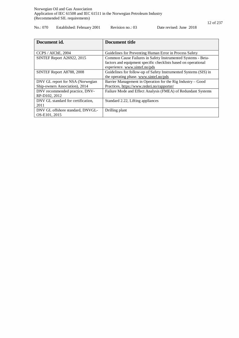
Document id. Document title
CCPS / AIChE, 2004 Guidelines for Preventing Human Error in Process Safety SINTEF Report A26922, 2015 Common Cause Failures in Safety Instrumented Systems - Beta-
factors and equipment specific checklists based on operational experience. www.sintef.no/pds
SINTEF Report A8788, 2008 Guidelines for follow-up of Safety Instrumented Systems (SIS) in the operating phase. www.sintef.no/pds
DNV GL report for NSA (Norwegian Ship-owners Association), 2014
Barrier Management in Operation for the Rig Industry – Good Practices, https://www.rederi.no/rapporter/
DNV recommended practice, DNV-RP-D102, 2012
Failure Mode and Effect Analysis (FMEA) of Redundant Systems
DNV GL standard for certification, 2011
Standard 2.22, Lifting appliances
DNV GL offshore standard, DNVGL-OS-E101, 2015
Drilling plant

Norwegian Oil and Gas Association Application of IEC 61508 and IEC 61511 in the Norwegian Petroleum Industry (Recommended SIL requirements) No.: 070 Established: February 2001 Revision no.: 03 Date revised: June 2018
13 of 237
4 Definitions and abbreviations
4.1 Definitions The definitions below are included for the purpose of clarification, using terminology familiar to the offshore industry. Where relevant, reference to the applicable standard or document is given. Definitions are also given in IEC 61511-1, cl. 3 and IEC 61508-4.
Barrier A measure intended to identify conditions that may lead to failure, hazard and
accident situations, prevent an actual sequence of events occurring or developing, influence a sequence of events in a deliberate way, or limit damage and/or loss. (PSA, 2017)
Barrier element Technical, operational and organisational measures or solutions involved in the
realisation of a barrier function (PSA, 2017) Barrier function The task or role of a barrier. (PSA, 2017) Barrier system System designed and implemented to perform one or more barrier function (NORSOK, Z-
013) NOTE 1: A frequently applied term comparable to barrier element but at a somewhat higher level. E.g. the emergency shutdown (ESD) system may be considered a barrier system whereas the ESV valves and ESD pushbuttons may be considered as barrier elements. NOTE 2: The terms barrier system and barrier are often interchanged
Barrier management Coordinated activities to establishing and maintaining barriers so that they fulfil their
function at all times (PSA, 2017) Barrier strategy Plan for how barrier functions, on the basis of the risk picture, are implemented
in order to reduce risk. (PSA 2017) Bypass Action or facility to prevent all or parts of the SIS functionality from being executed (IEC
61511-1, cl. 3.2.4) Common cause failure Concurrent failures of different devices, resulting from a single event, where these
failures are not consequences of each other (IEC 61511-1, cl. 3.2.6.1) Dangerous failure A failure that impedes or disables a given safety action (IEC 61511-1, cl. 3.2.11)
NOTE: A fraction of these failures will be revealed by automatic diagnostic tests and are denoted “dangerous detected failures”. The residual dangerous failures, not detected by self-test, are denoted “dangerous undetected failures”.
Fire area Area separated from other areas either by physical barriers (fire/blast partition) or distance
which will prevent a dimensioning fire spreading (NORSOK S-001, section 3.1.6) Functional Safety Assessment
Investigation, based on evidence, to judge the functional safety achieved by one or more SIS and/or other protection layers (IEC 61511-1, cl. 3.2.24)
Global safety function Global safety functions, or “fire and explosion hazard safety functions”, are functions
which typically provide protection for one or several fire areas. Examples are emergency shutdown, isolation of ignition sources and emergency blow down
Inhibit/blocking Disabling of the function input and prevention of shutdown action; e.g., by disabling of
the input signal to the shutdown logic while presenting the alarm to the operator Integrity level deviation In this document the term integrity level deviation is applied to denote a departure from
the requirements specified in the minimum SIL table
Norwegian Oil and Gas Association Application of IEC 61508 and IEC 61511 in the Norwegian Petroleum Industry (Recommended SIL requirements) No.: 070 Established: February 2001 Revision no.: 03 Date revised: June 2018
14 of 237
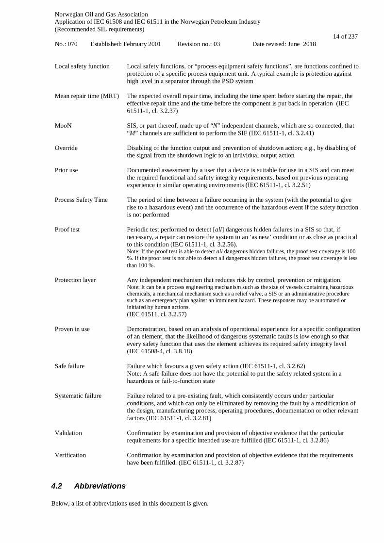
Local safety function Local safety functions, or “process equipment safety functions”, are functions confined to protection of a specific process equipment unit. A typical example is protection against high level in a separator through the PSD system
Mean repair time (MRT) The expected overall repair time, including the time spent before starting the repair, the
effective repair time and the time before the component is put back in operation (IEC 61511-1, cl. 3.2.37)
MooN SIS, or part thereof, made up of “N” independent channels, which are so connected, that
“M” channels are sufficient to perform the SIF (IEC 61511-1, cl. 3.2.41) Override Disabling of the function output and prevention of shutdown action; e.g., by disabling of
the signal from the shutdown logic to an individual output action Prior use Process Safety Time
Documented assessment by a user that a device is suitable for use in a SIS and can meet the required functional and safety integrity requirements, based on previous operating experience in similar operating environments (IEC 61511-1, cl. 3.2.51) The period of time between a failure occurring in the system (with the potential to give rise to a hazardous event) and the occurrence of the hazardous event if the safety function is not performed
Proof test Periodic test performed to detect [all] dangerous hidden failures in a SIS so that, if
necessary, a repair can restore the system to an ‘as new’ condition or as close as practical to this condition (IEC 61511-1, cl. 3.2.56). Note: If the proof test is able to detect all dangerous hidden failures, the proof test coverage is 100 %. If the proof test is not able to detect all dangerous hidden failures, the proof test coverage is less than 100 %.
Protection layer
Any independent mechanism that reduces risk by control, prevention or mitigation. Note: It can be a process engineering mechanism such as the size of vessels containing hazardous chemicals, a mechanical mechanism such as a relief valve, a SIS or an administrative procedure such as an emergency plan against an imminent hazard. These responses may be automated or initiated by human actions. (IEC 61511, cl. 3.2.57)
Proven in use Demonstration, based on an analysis of operational experience for a specific configuration of an element, that the likelihood of dangerous systematic faults is low enough so that every safety function that uses the element achieves its required safety integrity level (IEC 61508-4, cl. 3.8.18)
Safe failure Failure which favours a given safety action (IEC 61511-1, cl. 3.2.62)
Note: A safe failure does not have the potential to put the safety related system in a hazardous or fail-to-function state
Systematic failure Failure related to a pre-existing fault, which consistently occurs under particular
conditions, and which can only be eliminated by removing the fault by a modification of the design, manufacturing process, operating procedures, documentation or other relevant factors (IEC 61511-1, cl. 3.2.81)
Validation
Confirmation by examination and provision of objective evidence that the particular requirements for a specific intended use are fulfilled (IEC 61511-1, cl. 3.2.86)
Verification Confirmation by examination and provision of objective evidence that the requirements
have been fulfilled. (IEC 61511-1, cl. 3.2.87)
4.2 Abbreviations Below, a list of abbreviations used in this document is given.

Norwegian Oil and Gas Association Application of IEC 61508 and IEC 61511 in the Norwegian Petroleum Industry (Recommended SIL requirements) No.: 070 Established: February 2001 Revision no.: 03 Date revised: June 2018
15 of 237
ABV - Annulus bleed valve AC - Acceptance criteria ADS - Automatic disconnect sequence/system ALARP - As low as reasonable practicable ASV - Annulus safety valve AMF - Automatic mode function AMV - Annulus master valve AS - Autoshear ASR - Automatic shutdown report AWV - Annulus wing valve BCM - Basic control module BCU - BOP control unit BDV - Blowdown valve BOP - Blow-out preventer BPCS - Basic process control system BSR - Blind shear ram CAP - Critical action panel CCF - Common cause failure CCR - Central control room CDD - Calculation and data dossier C&E - Cause and effect CF - Correction factor CIDH - Chemical injection valve (downhole) CIXT - Chemical injection valve (Xmas tree) CM - Corrective maintenance CPI - Computer point index CPU - Central processing unit CSR - Casing shear ram CT - Coiled tubing C/WO - Completion/Workover DC - Diagnostic coverage DCV - Directional control valve DHSV - Downhole safety valve DM - Deadman DP - Dynamic positioning DR - Demand rate DTU - Downtime unavailability DU - Dangerous undetected ECD - Equivalent circulating density EDS - Emergency disconnect sequence/system EERS - Evacuation, escape and rescue strategy EPC - Engineering, procurement & construction EPU - Electric power unit EQD - Emergency quick disconnect ESD - Emergency shutdown ESV - Emergency shutdown valve EUC - Equipment under control FALL - Flow alarm low low FAT - Factory acceptance test FDS - Functional design specification FEED - Front-end engineering design FES - Fire and explosion strategy FF - Failure fraction F&G - Fire and gas FGS - F&G system FMEA - Failure mode effect analysis FMECA - Failure mode effect and criticality analysis FMEDA - Failure mode effect and diagnostic analysis FPL - Fixed program language FS - Functional specification FSA - Functional safety assessment
Norwegian Oil and Gas Association Application of IEC 61508 and IEC 61511 in the Norwegian Petroleum Industry (Recommended SIL requirements) No.: 070 Established: February 2001 Revision no.: 03 Date revised: June 2018
16 of 237
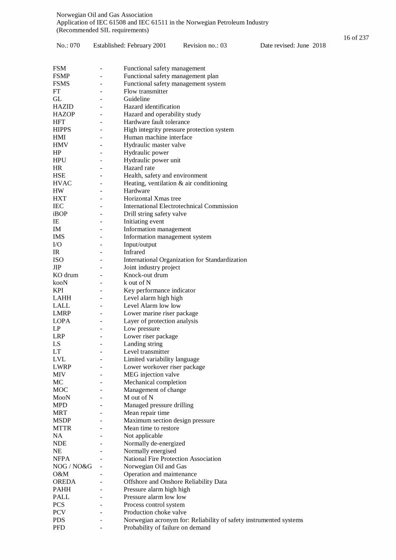
FSM - Functional safety management FSMP - Functional safety management plan FSMS - Functional safety management system FT - Flow transmitter GL - Guideline HAZID - Hazard identification HAZOP - Hazard and operability study HFT - Hardware fault tolerance HIPPS - High integrity pressure protection system HMI - Human machine interface HMV - Hydraulic master valve HP - Hydraulic power HPU - Hydraulic power unit HR - Hazard rate HSE - Health, safety and environment HVAC - Heating, ventilation & air conditioning HW - Hardware HXT - Horizontal Xmas tree IEC - International Electrotechnical Commission iBOP - Drill string safety valve IE - Initiating event IM - Information management IMS - Information management system I/O - Input/output IR - Infrared ISO - International Organization for Standardization JIP - Joint industry project KO drum - Knock-out drum kooN - k out of N KPI - Key performance indicator LAHH - Level alarm high high LALL - Level Alarm low low LMRP - Lower marine riser package LOPA - Layer of protection analysis LP - Low pressure LRP - Lower riser package LS - Landing string LT - Level transmitter LVL - Limited variability language LWRP - Lower workover riser package MIV - MEG injection valve MC - Mechanical completion MOC - Management of change MooN - M out of N MPD - Managed pressure drilling MRT - Mean repair time MSDP - Maximum section design pressure MTTR - Mean time to restore NA - Not applicable NDE - Normally de-energized NE - Normally energised NFPA - National Fire Protection Association NOG / NO&G - Norwegian Oil and Gas O&M - Operation and maintenance OREDA - Offshore and Onshore Reliability Data PAHH - Pressure alarm high high PALL - Pressure alarm low low PCS - Process control system PCV - Production choke valve PDS - Norwegian acronym for: Reliability of safety instrumented systems PFD - Probability of failure on demand

Norwegian Oil and Gas Association Application of IEC 61508 and IEC 61511 in the Norwegian Petroleum Industry (Recommended SIL requirements) No.: 070 Established: February 2001 Revision no.: 03 Date revised: June 2018
17 of 237
PFH - Probability of failure per hour PHA - Process hazard analysis P&ID - Process and instrumentation diagram PLC - Programmable logic controller PM - Preventive maintenance PMV - Production master valve POCV - Pilot operated check valve PSA - Petroleum Safety Authority Norway PSD - Process shutdown PST - Partial stroke testing PSV - Process relief valve PT - Pressure transmitter PTIF - Probability of test independent failure PWV - Production wing valve QA - Quality assurance QRA - Quantitative risk analysis RBD - Reliability block diagram RCD - Rotating control device RLWI - Riserless light well intervention RNNP - Risk level in the Norwegian petroleum activity (Risikonivå i norsk petroleumsvirksomhet) ROV - Remotely operated vehicle RRV - Riser retainer valve SAR - Safety analysis report SAS - Safety and automation system SAT - Safety analysis table SCD - System control diagram SCM - Subsea control module SDS - Safe disconnect system SEM - Subsea electronics module SFF - Safe failure fraction SFT - Surface flow tree SIF - Safety instrumented function SIL - Safety integrity level SIS - Safety instrumented system SOV - Solenoid valve SPM - Sub plate mounted SRS - Safety requirements specification SSTT - Subsea (sub-Surface) test tree SW - Software TAHH - Temperature alarm high high TALL - Temperature alarm low low TC - Test coverage TIF - Test independent failure TT - Temperature transmitter UPS - Uninterrupted power supply V&V - Validation and verification VXT - Vertical Xmas tree WL - Wireline WO - Workover WOS - Workover system WOCS - Workover control system XMT - Xmas tree XMV - Xmas tree valve XOV - Cross-over valve XV - Process shutdown valve XT - Xmas tree
Norwegian Oil and Gas Association Application of IEC 61508 and IEC 61511 in the Norwegian Petroleum Industry (Recommended SIL requirements) No.: 070 Established: February 2001 Revision no.: 03 Date revised: June 2018
18 of 237
5 Management of functional safety
5.1 Objective The objective of this chapter is to describe management activities to ensure that functional safety requirements are met. Health, Safety and Environment (HSE) management within the scope of IEC 61508 and IEC 61511 constitutes all activities necessary to ensure that the SIL requirements are identified, designed and maintained during the entire lifecycle of the systems. These activities are referred to as management of functional safety. It should be noted that the term “HSE management” in general has a broader scope than the IEC 61508 and IEC 61511 interpretation. Safety related aspects of an installation like conceptual design, structural and stability aspects, total system design and operation, drilling, environment aspects, working environment, construction safety, interface between operator and integrators etc., all need to be included in the overall management system.
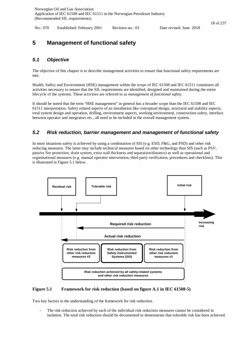
5.2 Risk reduction, barrier management and management of functional safety In most situations safety is achieved by using a combination of SIS (e.g. ESD, F&G, and PSD) and other risk reducing measures. The latter may include technical measures based on other technology than SIS (such as PSV, passive fire protection, drain system, extra wall thickness and separation/distance) as well as operational and organisational measures (e.g. manual operator intervention, third party verification, procedures and checklists). This is illustrated in Figure 5.1 below.
Risk reduction achieved by all safety-related systems and other risk reduction measures
Residual risk Tolerable risk Initial risk
Required risk reduction Increasingrisk
Risk reduction from Safety Instrumented
Systems (SIS)
Risk reduction from other risk reduction
measures #2
Actual risk reduction
Risk reduction from other risk reduction
measures #1
Figure 5.1 Framework for risk reduction (based on figure A.1 in IEC 61508-5) Two key factors in the understanding of the framework for risk reduction.
- The risk reduction achieved by each of the individual risk reduction measures cannot be considered in isolation. The total risk reduction should be documented to demonstrate that tolerable risk has been achieved.

Norwegian Oil and Gas Association Application of IEC 61508 and IEC 61511 in the Norwegian Petroleum Industry (Recommended SIL requirements) No.: 070 Established: February 2001 Revision no.: 03 Date revised: June 2018
19 of 237
- The risk reduction achieved by a safety-instrumented function (SIF) shall include all aspects of the barrier of which the SIF may only be a part. For example, the reliability of the initiating element (e.g. a push button) and the reliability of the final element (e.g. a valve) need to be known as well as the reliability of the SIF, to determine the reliability of the barrier.
The main purpose of barrier management is to establish and maintain the barriers to prevent an undesirable incident from occurring and/or by limiting the consequences should such an incident occur. Barrier management includes the processes, systems, solutions and measures that shall be in place to ensure the necessary risk reduction through the implementation and follow-up of barriers. As part of the barrier management, a separate installation specific barrier strategy document shall be developed (also referred to as safety strategy). This document shall describe relevant hazards and accidents during operation, and all barrier functions and associated barrier elements that are required to deal with these situations. The barrier strategy shall also include performance requirements or references to performance requirements that apply for the barrier elements for the specific installation. For safety instrumented functions, the performance requirements on availability can be determined from the IEC 61511 framework for risk reduction. Alternatively, for the most common SIFs, with relevant operating experience and with risks well understood, the minimum SIL requirements in section 7 in this guideline can be applied. The performance requirements should be included in the SRS, (ref. section 7.7). This also applies to safety instrumented functions that have been modified or functions that originally were not developed according to IEC 61511. For further reading, reference is made to the memo "Principles for barrier management in the petroleum industry, BARRIER MEMORANDUM 2017". Whereas barrier management shall include all safety-related systems and measures in place to reduce the risk to an acceptable level, management of functional safety in the context of IEC 61511-1, cl. 5 limits itself to deal with risk reduction from the SIS/SIF. Hence, management of functional safety can be considered a subset of barrier management.
5.3 Competence Requirements All activities that affect the safety life cycle of the SIS shall be managed and performed by personnel who are competent to do so in accordance with the relevant requirements in IEC 61508 and IEC 61511. All personnel and organisational units responsible for carrying out and reviewing each of the safety lifecycle phases shall be identified and be informed of the responsibilities assigned to them. A procedure shall be in place to manage competence of all those involved in the SIS life cycle. Periodic assessments should be carried out to document the competence of individuals against the activities they are performing and on replacement of an individual within a role (ref. IEC 61511-1, cl. 5.2.2.3).
5.3.1 SIS design Typically, the design phase involves a number of different companies and organisations. Hence, the work will normally be split between engineering contractors, manufacturers, control system vendors, field equipment vendors, etc., with the subsequent possibility of ambiguous responsibilities. One responsible company and associated responsible person (SIS authority) should be identified for each activity and each phase of the SIS safety lifecycle.
5.3.2 SIS follow-up during operation The person or job position with overall responsibility for the SIS shall ensure that the system performance is in accordance with the SIS safety requirements specification also during operation. This includes:
• Ensure that operations and testing/maintenance procedures (ref. chapter 10) are available and used as intended. In particular, ensure that appropriate records are maintained with respect to test results, maintenance activities, system failures and failure types, demand rate on the system and changes made to the SIS;
• Ensure that the competency of operators, maintenance technicians and engineers who work with or on the safety system is adequate;
• Ensure that access control to the safety system including the use of keys and passwords is in place; • Ensure that management of change procedures as defined in chapter 11 are available and applied.
Norwegian Oil and Gas Association Application of IEC 61508 and IEC 61511 in the Norwegian Petroleum Industry (Recommended SIL requirements) No.: 070 Established: February 2001 Revision no.: 03 Date revised: June 2018
20 of 237
Competence requirements shall be specified for all SIS follow-up activities. Key issues important for all persons involved in SIS follow-up, are to:
• Understand the purpose and functional requirements of the SIS; • Understand the hazards against which the SIS is protecting; • Be aware of operational and environmental constraints under which the SIS shall operate;
For personnel that are involved in SIS testing and maintenance (ref. section 10.5) it is also important to have knowledge related to:
• Be aware of what “as good as new” means for different SIS components, and what actions that shall be taken
to restore the equipment to this condition; • Be familiar with relevant test and maintenance procedures including procedures for failure recording and
classification. • Understand the terminology of a dangerous failure as well as critical failure modes (i.e. failure modes that
may cause loss of the main function(s) of the equipment), relevant failure causes and detection methods for the different equipment types.
• Understand the importance of as detailed as possible reporting of failures in the maintenance system. • Be familiar with management of change (MOC) procedures, e.g. only a one-to-one replacement allowed as a
maintenance repair activity Personnel that are directly involved in SIS monitoring and verification (ref. section 10.6) should have additional knowledge related to:
• Basic concepts used in reliability assessments, including failure classification, failure rates, probability of failure on demand (PFD) and common cause failures (CCFs);
• Basic principles for calculating the PFD from a reliability block diagram and techniques to analyse failure modes and effects (FMEA, FMECA and FMEDA);
• Governing rules and relevant standards, e.g. Petroleum Safety Authority regulations, IEC 61508 / 61511 and this guideline;
• All SIS related documentation, including the SRS and design documentation that shall be kept updated, • Operation and maintenance procedures including SIS related company specific procedures and guidelines; • Conditions that apply for the SIS to remain (sufficiently) independent from other systems (protection layers).
5.4 Safety planning IEC 61511-1, cl. 5 requires that planning shall take place to define the activities required to ensure functional safety of the SIS. An important planning document is the Functional Safety Management Plan (FSMP). This plan describes the main functional safety management process, activities and executives throughout the lifecycle of the SIS and is required for a particular plant rather than individual documents for each modification and expansion project. In Appendix E a number of example documents with structure and content are given for selected documentation. This includes:
• Functional safety management plan (FSMP) • Safety requirements specification (SRS) • Safety analysis report (SAR) • SIL compliance report • Application program safety requirements
Note that ‘safety manual’ in some cases can substitute a SAR, cf. Table 8.5.
5.5 Function safety audits and revisions The purpose of the audit is to review relevant documentation to determine whether the functional safety management system (FSMS) is in place, up to date, and being followed. Where gaps are identified, recommendations for improvements are made. Reference is made to IEC 61511-1, cl. 5.2.6.2 for further requirements.

Norwegian Oil and Gas Association Application of IEC 61508 and IEC 61511 in the Norwegian Petroleum Industry (Recommended SIL requirements) No.: 070 Established: February 2001 Revision no.: 03 Date revised: June 2018
21 of 237
5.6 Verification IEC 61511-1, cl. 3 defines verification as confirmation by examination and provision of objective evidence that the requirements have been fulfilled. It is further stated that this is the activity of demonstrating for each phase of the relevant SIS safety life-cycle by analysis and/or tests, that, for specific inputs, the outputs meet in all respects the objectives and requirements set for the specific phase. Hence, the objective of verification is to demonstrate that the required outputs satisfy the defined requirements for the appropriate phases as identified by the verification planning. Such planning shall be carried out throughout the SIS safety life-cycle and shall define all activities required for the appropriate phase of the safety life-cycle. See also IEC 61511-1, cl. 7.
5.7 Validation IEC 61511-1, cl. 3.2.86 defines validation as confirmation by examination and provision of objective evidence that the particular requirements for a specific intended use are fulfilled. Requirements to SIS safety validation is given in IEC 61511-1, cl. 15. In the context of IEC 61511-1, cl.3.2.86, SIS validation shall be performed after installation to demonstrate that the SIF(s) and SIS meet the SRS in all respects. Since validation is scheduled only at this stage, it will most probably result in several non-conformities. It is therefore recommended that additional validation activities run in parallel throughout the entire design phase, e.g. during the detailing of specifications. In particular, the team members should participate in safety related design review activities like HAZOP. Since changes identified at a late stage (e.g. after installation) are often costly, it is recommended to perform "validation" activities also earlier in the lifecycle. E.g. this implies that the SRS during design should not only be checked with respect to whether the requirements can be fulfilled, but also consider limitations related to the specific application (intended use). Such activities may include design reviews, internal document checks and functional safety assessment (ref. chapter 6).
Norwegian Oil and Gas Association Application of IEC 61508 and IEC 61511 in the Norwegian Petroleum Industry (Recommended SIL requirements) No.: 070 Established: February 2001 Revision no.: 03 Date revised: June 2018
22 of 237
6 Functional Safety Assessment
6.1 Objective The FSA is an investigation which, based upon evidence, makes judgements on the functional safety and safety integrity achieved by every SIF. IEC 61511-1, cl. 3.2.24 (Definition) and cl. 5.2.6.1 (FSA) including cl. 5.2.6.2 and additional guidance given in IEC 61511-2, address attributes of FSA execution including reference to issues such as procedure, planning, accountable standards and practices, evidence, independence, assessors, competence, scope etc. The person responsible for the SIF should initiate the FSA and appoint an FSA leader and a team of competent and persons with relevant experience to carry out the investigation.
6.2 FSA execution According to IEC 61511-1, cl. 5.2.6.1 an FSA should be considered at the following stages:
1. After the hazard and risk assessment has been carried out, the required protection layers have been identified and the SRS has been developed, e.g., prior to completion of front-end engineering and start of detailed engineering;
2. After the SIS has been designed, e.g., prior to completion of detailed engineering; 3. After the installation and commissioning of the SIS has been completed and operation and maintenance
procedures have been developed, e.g., ready for start-up. 4. After gaining experience in operating and maintenance 5. After modification and prior to decommissioning of a SIS Note 1: The FSA should be undertaken in due time such that possible shortfalls and recommendations can be resolved without significant disruption to continuation of activities. Due caution should be made to the fact that a project may be delayed or a plant shut down as a consequence of safety critical gaps disclosed during the FSA. Note 2: According to IEC 61511-1, cl. 5.2.6.1.5 it is mandatory to perform FSA prior to the hazards being present, i.e. at stage 3 listed above.
FSA activities depend on and should be adapted to the project type, size and complexity. The complete SIFs should be reviewed across project boundaries and contractual interfaces. Issues considered during FSA stage 4, 5 and partly stage 3, will be the responsibility of the operator and FSA coordination during these stages will therefore usually be performed by operator. FSA team scope of work should incorporate the following activities:
• Ensure that resources needed, both independent personnel and internal resources, are identified. • Prepare for, organise and facilitate investigations to be performed including FSA workshops and reporting of
the work and results. • Establish a terms of reference for the investigation to suit the stage, type of project, complexity etc., e.g., by
use of a checklist approach. • Perform a review (“table top”) of relevant information, and establish and issue a questionnaire for the
responsible SIS project parties prior to any workshop, and arrange workshop clarification meetings. • The FSA investigation should address whether the following are in place, adequate and being followed (see
also IEC 61511-1,cl. 5.2.6.1.4 and cl. 5.2.6.1.5): o SIS/SIF documents relevant of each lifecycle phase and stage of the project. o Functional safety management, e.g., issued FSMP. o Assessment to identify hazards, risk and other conditions that have an impact on SIS/SIF. o Methodology and basis for determination of SIF requirement. o SRS, incorporating both hardware and software. o SIS design in view of safety integrity but also overall reliability, in compliance with project SRS
and context of IEC 61511 (random selection but attention made to SIS/SIF of high criticality). o Operating and maintenance procedures o Verification status

Norwegian Oil and Gas Association Application of IEC 61508 and IEC 61511 in the Norwegian Petroleum Industry (Recommended SIL requirements) No.: 070 Established: February 2001 Revision no.: 03 Date revised: June 2018
23 of 237
Note: The main purpose of an FSA is to make a judgement on whether the functional safety and safety integrity achieved by every SIF is as specified in the SRS. Design reviews and verifications to decide upon SIS/SIF conformance to relevant specifications is part of a project QA/QC activities like verification and validation, e.g., compliance to design basis / prerequisites, used data and calculations, vendor safety analysis reports etc.
The results from reviews (“table tops”), interviews and workshops shall be summarised in a final FSA report including:
• Summary and overall judgement, i.e., success factor, key observations and actions. This will reflect the FSA team's judgement on whether deficiencies are present that can significantly impede or adversely affect the SIS safety performance and functionality.
• Checklists (when applied) duly filled in according to defined FSA scope. • Status of selected SIS and relevant documentation, e.g., fulfilment of requirements, quality of
documentation, etc. • List of findings and actions and due dates for closing of actions.

Norwegian Oil and Gas Association Application of IEC 61508 and IEC 61511 in the Norwegian Petroleum Industry (Recommended SIL requirements) No.: 070 Established: February 2001 Revision no.: 03 Date revised: June 2018
24 of 237
7 Determining SIL requirements
7.1 Objective The overall objective of this chapter is to describe a methodology for determining SIL requirements for safety instrumented functions. This includes:
• to identify barrier elements for the reduction of risks related to the use and operation of the associated equipment
• to define the need for instrument-based protective systems and other measures • to determine SIFs that shall be allocated a Safety integrity level (SIL) to be performed by the SIS • to describe minimum SIL/PFD requirements • to identify and propose how to handle functions not applicable by the minimum SIL table (either not handled
by the minimum SIL tables or when the prerequisites differs) Since this guideline provides minimum SIL/PFD requirements for the most common instrumented safety functions, allocation of safety functions to protection layers (IEC 61511-1, cl.9) is not described as a separate activity in this chapter.
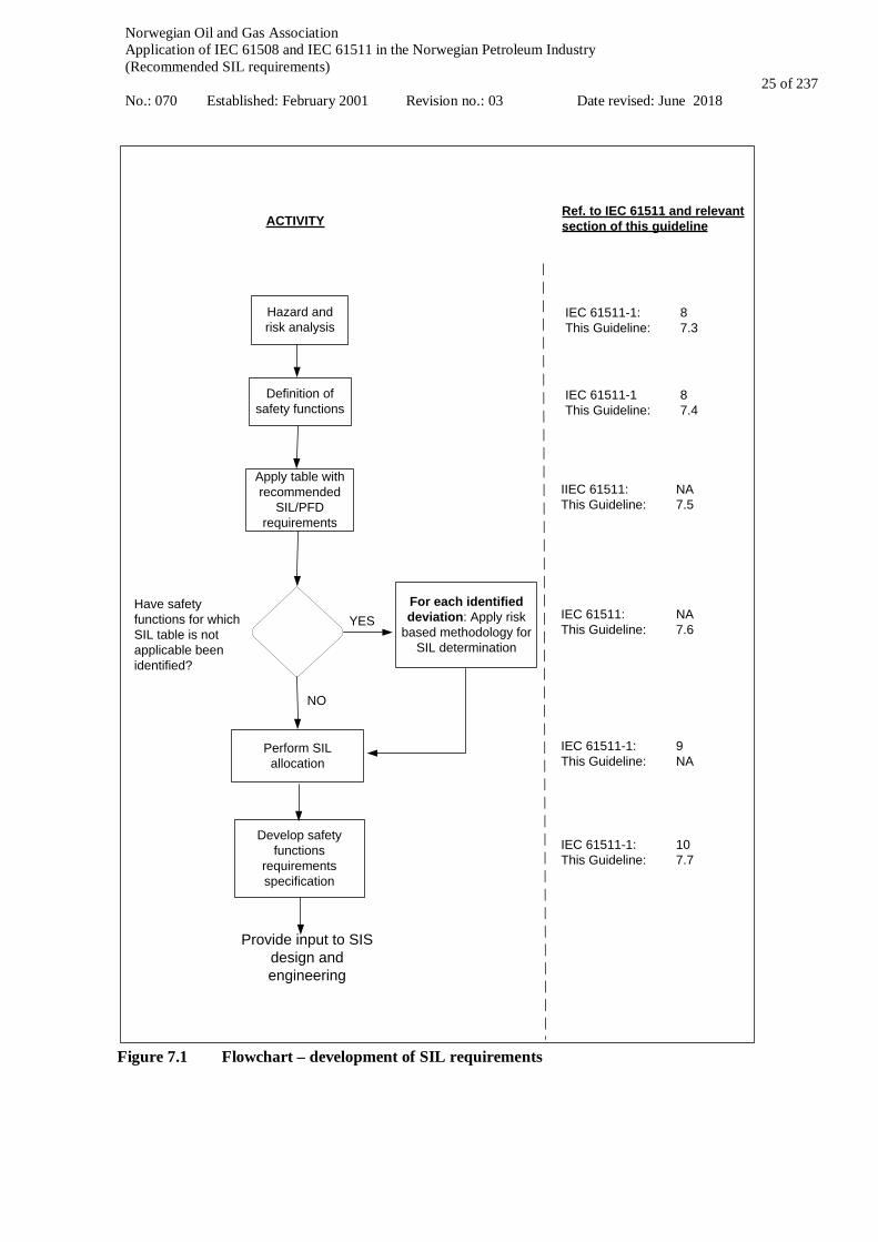
7.2 Approach Relevant requirements are given in IEC 61511-1 clauses 8 and 9. As discussed in section 1.1 and chapter 2, the main argument for introducing minimum SIL requirements is to standardize and simplify the risk based approach and to ensure that the performance of new or modified SIFs are benchmarked against similar functions that through operation and historical records have demonstrated satisfactory reliability. For global safety functions such as ESD and F&G, it has proven difficult to allocate SIL requirements based on risk based approaches. Therefore in section 7.5 a table of minimum SIL requirements (accompanied by some maximum PFD requirements) are given for a number of frequently applied functions. This includes process shutdown, emergency shutdown, fire and gas functions, some BOP functions and specific workover functions. Deviation from the minimum requirements can arise when the design differs from conventional solutions specified in ISO 10418 / API RP 14C, when assumptions stated in Appendix A are not fulfilled, or when functions are not covered by the minimum SIL table, e.g. due to technological advances, particular risks or special conceptual or operational aspects. These functions need to be treated according to IEC 61511 methodology, i.e. the safety integrity level should be based upon a qualitative or quantitative risk based method (cf. section 7.6). Figure 7.1 illustrates the process for developing SIL requirements as described in this chapter. This covers the lifecycle phases as represented by boxes 1-3 in Figure 2.2.
Norwegian Oil and Gas Association Application of IEC 61508 and IEC 61511 in the Norwegian Petroleum Industry (Recommended SIL requirements) No.: 070 Established: February 2001 Revision no.: 03 Date revised: June 2018
25 of 237
Hazard and risk analysis
Definition of safety functions
NO
Apply table with recommended
SIL/PFD requirements
YESFor each identified deviation: Apply risk
based methodology for SIL determination
Perform SIL allocation
Develop safety functions
requirements specification
ACTIVITYRef. to IEC 61511 and relevant section of this guideline
IEC 61511-1: 8This Guideline: 7.3
IEC 61511-1 8This Guideline: 7.4
IIEC 61511: NAThis Guideline: 7.5
IEC 61511: NAThis Guideline: 7.6
IEC 61511-1: 10This Guideline: 7.7
IEC 61511-1: 9This Guideline: NA
Have safety functions for which SIL table is not applicable been identified?
Provide input to SISdesign and engineering
Figure 7.1 Flowchart – development of SIL requirements
Norwegian Oil and Gas Association Application of IEC 61508 and IEC 61511 in the Norwegian Petroleum Industry (Recommended SIL requirements) No.: 070 Established: February 2001 Revision no.: 03 Date revised: June 2018
26 of 237
7.3 Hazard and risk analysis
7.3.1 Scope of hazard and risk analysis The hazard and risk analysis shall, according to IEC 61511-1, cl. 8, determine the following issues: • the hazards and the hazardous events of the process and associated control equipment; • the event sequence leading to the hazards; • the risk associated with the identified hazards; • the requirements for risk reduction. The hazard and risk analysis shall consider all reasonable foreseeable circumstances including possible fault conditions, misuse and extreme environmental conditions. The hazard and risk analysis shall also consider possible human errors, and abnormal or infrequent modes of operation of the process. Risk-based methods as listed in IEC 61511 (e.g. LOPA, risk graph) should comply with the following:
• Such methods should not be used as a mean to justify the exclusion of barriers and safety systems which are enforced by PSA regulations and/or recognized standards.
• An instrument-based protective measure required according to recognized industry standards should always be implemented in a safety instrumented system.
As discussed in section 7.2, a table with minimum SIL/PFD requirements for determination of integrity levels for “standard” safety functions is provided. This approach, as compared to a fully risk based IEC 61511 analysis, may limit part of the required scope and extent of the risk analysis (e.g. SIL allocation), and will direct focus towards the hazard identification, the identification of each SIF and in particular the identification of deviations from the minimum SIL table.
7.3.2 Process Hazard Analysis (PHA) Process hazard analysis (PHA), such as hazard identification study (HAZID) and/or hazard and operability study (HAZOP) or safety analysis tables (SATs), shall be performed for the defined process and associated systems. The objective of the PHA is to identify the inherent hazard potential of the process, without safety related functions present. The PHA shall be sufficiently detailed so as to enable identification of potential deviations from the minimum SIL table. The PHA should be carried out with due consideration to issues such as: • properties of the fluids and gases being handled; • operating and maintenance procedures; • the different operations and operational modes affecting the process, such as start-up, shutdown, maintenance,
pigging, well interventions, etc.; • hazards arising from human intervention with the process and associated systems, i.e. the effect of
human/operational errors; • the novelty and complexity of the installation and interfaces under consideration; • the subsequent need for special protection functions due to the hazards identified; • whether a failure of the BPCS can cause separate hazards and/or a demand on the SIS/SIF. In order to reduce the chance of omitting any hazards during the examination of the process, the hazard identification should be performed by a multidiscipline team covering the relevant engineering disciplines and operational and maintenance experience. The type of technique(s) applied for identification of hazards will depend on factors such as the lifecycle stage at which the identification is undertaken (information available) and the type and complexity of the installation. Generally, the more novel and complex an installation, the more “structured” approach is required. For a more detailed discussion of this topic, see e.g. ISO 17776; “Guidelines on tools and techniques for identification and assessment of hazardous events”. Reference is also made to IEC 61882 “Hazard and Operability studies (HAZOP studies)”.
Norwegian Oil and Gas Association Application of IEC 61508 and IEC 61511 in the Norwegian Petroleum Industry (Recommended SIL requirements) No.: 070 Established: February 2001 Revision no.: 03 Date revised: June 2018
27 of 237
7.4 Definition of safety instrumented functions and SIL allocation 7.4.1 Scope Relevant requirements are given in IEC 61511-1, cl. 8 and cl. 9.2. The overall objective of this activity is to identify and list all the SIFs and allocate SIL requirements either by:
• conformance with the minimum SIL table (ref. section 7.5) or similar deterministic approach, or • the application of a risk-based approach as promoted by IEC 61511.
This includes:
• Describe the SIFs required to protect against the risks identified; • Define and list the safety instrumented functions to be implemented by SIS; • Identify where the design deviates from recognized standard and the minimum SIL table cannot be applied.
These cases shall be handled separately and SIL allocated by a risk-based approach (ref section 7.6) The minimum SIL requirements given in Tables 7.5.1, 7.5.2, 7.5.3, 7.5.4 and 7.5.5 cover the most common SIFs and should not be considered an exhaustive source for identification of SIFs and SIL allocation. 7.4.2 Requirements IEC 61511-1, cl. 8.2.1 states that SIFs shall be identified. This should be based on a multidiscipline review to ensure understanding of the system design risk and in the identification of the required SIFs. Key design documentation to be applied includes e.g. P&IDs, C&Es, input from PHA studies including recommendations, and Safety Analysis Tables (SAT) for process safety design following ISO 10418. Issues such as initiating events, demand rate, independence between safety functions, consequences of failure, process safety time etc. should be identified and documented for each SIF to verify applicability of the minimum SIL table. There should be a focus on the assumptions underlying the typical SIFs (ref. Appendix A) and whether it is required to deviate from these. Example of issues that should be assessed:
• risk driven by environmental impact, e.g. particularly vulnerable areas; • design more complex than assumed in the typical functions described in Appendix A; • special process conditions (e.g. high pressure, high temperature);, • consequences expected are far higher than assumed in the typical SIS/SIF application (e.g. total loss of the
facility such as a gas blow in the hull which may cause the loss of the facility structural integrity); • high demand rate; • system design differing from conventional solutions as specified in ISO 10418 (e.g. PSVs not designed for
the full flow, non-conventional pressure protection used); • the facility QRA shows that the estimated overall risk is above the acceptance criteria indicating stricter
requirements to relevant functions (e.g. a particularly high number of import risers to a facility) SIF identification and SIL allocation exercise should be performed in close liaison with the HAZOP in order to obtain synergy effects (e.g. performing these activities either simultaneously or subsequently involving the same core members). The SIFs should be defined such that all equipment, including utility systems, power supplies etc., required to fulfil the specified safety function are included. If these systems are judged to give a significant contribution towards the unavailability of the SIF, these systems should also be included in the PFD calculations. Requirements for global safety functions such as ESD and F&G functions, are to a large degree specified in the PSA regulations (ref. the Facility Regulations) and NORSOK. Additional requirements relevant to the global safety functions may follow from the QRA or from preparing the Fire and Explosion Strategy (FES, ref. ISO 13702). Based on the SIF identification and SIL allocation exercise, deviations from the minimum SIL/PFD requirements and applicable premises may be identified. Definition and handling of such cases are further described in section 7.6. For all other SIFs, confirmed similar to the typical SIS/SIF, the minimum SIL requirements as given in section 7.5 may be applied without need to perform further risk analysis.

Norwegian Oil and Gas Association Application of IEC 61508 and IEC 61511 in the Norwegian Petroleum Industry (Recommended SIL requirements) No.: 070 Established: February 2001 Revision no.: 03 Date revised: June 2018
28 of 237
7.5 Minimum SIL requirements Relevant requirements are given in IEC 61511-1, cl. 9.2. Tables 7.5.1, 7.5.2, 7.5.3, 7.5.4 and 7.5.5 below presents the minimum SIL requirements for local SIFs (PSD functions), global SIFs (ESD, F&G, etc.), subsea SIFs, some BOP functions and workover related SIFs. When deriving these requirements, the main objective has been to ensure a performance considered achievable by todays’ standards and industry practices. Therefore, for a number of SIL 1 functions, where the "allowed" probability of failure on demand (PFD) can range between 0.1 and 0.01, a specific PFD requirement has been given to ensure a certain reliability of the function. For several safety functions, and in particular global safety functions like ESD, blowdown and F&G functions, it has been difficult to establish generic definitions. Due to installation specific conditions, design and operational philosophies etc., the number of final elements to be activated upon a specified cause will for example differ from case to case. Consequently, several of the requirements are given on a sub-function level rather than for a complete safety function. See also definition of local and global safety functions in section 4.1. It is also important to emphasise that the minimum SIL requirements given in the tables are only one part of the requirements that shall be fulfilled in order to ensure compliance with IEC 61511 and this document. As discussed in other sections of this document, management of functional safety, architectural constraints on hardware safety integrity, behaviour upon detection of a fault and control and avoidance of systematic faults shall also be considered for SIS equipment to comply with IEC 61511. See also section 8.4.2. on prior use. Note that the table shall be read in conjunction with the premises and requirements in section 7.4.2 and the assumptions given in Appendix A. Detailed definitions of the safety functions and background information concerning assumed failure rates, critical failure modes, test intervals and other assumptions are given in Appendix A.
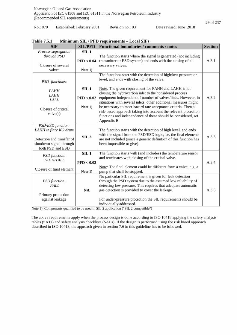
Norwegian Oil and Gas Association Application of IEC 61508 and IEC 61511 in the Norwegian Petroleum Industry (Recommended SIL requirements) No.: 070 Established: February 2001 Revision no.: 03 Date revised: June 2018
29 of 237
Table 7.5.1 Minimum SIL / PFD requirements – Local SIFs
SIF SIL/PFD Functional boundaries / comments / notes Section Process segregation
through PSD
Closure of several valves
SIL 1
PFD < 0.04
Note 1)
The function starts where the signal is generated (not including transmitter or ESD system) and ends with the closing of all necessary valves.
A.3.1
PSD functions:
PAHH LAHH LALL
Closure of critical
valve(s)
SIL 1
PFD < 0.02
Note 1)
The functions start with the detection of high/low pressure or level, and ends with closing of the valve. Note: The given requirement for PAHH and LAHH is for closing the hydrocarbon inlet to the considered process equipment independent of number of valves/lines. However, in situations with several inlets, other additional measures might be necessary to meet hazard rate acceptance criteria. Then a risk-based approach taking into account the relevant protection functions and independence of these should be considered, ref. Appendix B.
A.3.2
PSD/ESD function: LAHH in flare KO drum
Detection and transfer of shutdown signal through
both PSD and ESD
SIL 3 The function starts with the detection of high level, and ends with the signal from the PSD/ESD logic, i.e. the final elements are not included (since a generic definition of this function has been impossible to give).
A.3.3
PSD function: TAHH/TALL
Closure of final element
SIL 1
PFD < 0.02
Note 1)
The function starts with (and includes) the temperature sensor and terminates with closing of the critical valve. Note: The final element could be different from a valve, e.g. a pump that shall be stopped.
A.3.4
PSD function: PALL
Primary protection
against leakage
NA
No particular SIL requirement is given for leak detection through the PSD system due to the assumed low reliability of detecting low pressure. This requires that adequate automatic gas detection is provided to cover the leakage. For under-pressure protection the SIL requirements should be individually addressed.
A.3.5
Note 1): Components qualified to be used in SIL 2 application ("SIL 2 compatible") The above requirements apply when the process design is done according to ISO 10418 applying the safety analysis tables (SATs) and safety analysis checklists (SACs). If the design is performed using the risk based approach described in ISO 10418, the approach given in section 7.6 in this guideline has to be followed.
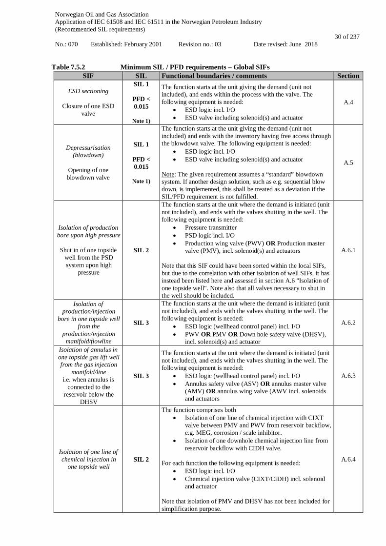
Norwegian Oil and Gas Association Application of IEC 61508 and IEC 61511 in the Norwegian Petroleum Industry (Recommended SIL requirements) No.: 070 Established: February 2001 Revision no.: 03 Date revised: June 2018
30 of 237
Table 7.5.2 Minimum SIL / PFD requirements – Global SIFs
SIF SIL Functional boundaries / comments Section
ESD sectioning
Closure of one ESD valve
SIL 1
PFD < 0.015
Note 1)
The function starts at the unit giving the demand (unit not included), and ends within the process with the valve. The following equipment is needed:
• ESD logic incl. I/O • ESD valve including solenoid(s) and actuator
A.4
Depressurisation (blowdown)
Opening of one blowdown valve
SIL 1
PFD < 0.015
Note 1)
The function starts at the unit giving the demand (unit not included) and ends with the inventory having free access through the blowdown valve. The following equipment is needed:
• ESD logic incl. I/O • ESD valve including solenoid(s) and actuator
Note: The given requirement assumes a “standard” blowdown system. If another design solution, such as e.g. sequential blow down, is implemented, this shall be treated as a deviation if the SIL/PFD requirement is not fulfilled.
A.5
Isolation of production bore upon high pressure
Shut in of one topside
well from the PSD system upon high
pressure
SIL 2
The function starts at the unit where the demand is initiated (unit not included), and ends with the valves shutting in the well. The following equipment is needed:
• Pressure transmitter • PSD logic incl. I/O • Production wing valve (PWV) OR Production master
valve (PMV), incl. solenoid(s) and actuators Note that this SIF could have been sorted within the local SIFs, but due to the correlation with other isolation of well SIFs, it has instead been listed here and assessed in section A.6 "Isolation of one topside well". Note also that all valves necessary to shut in the well should be included.
A.6.1
Isolation of production/injection
bore in one topside well from the
production/injection manifold/flowline
SIL 3
The function starts at the unit where the demand is initiated (unit not included), and ends with the valves shutting in the well. The following equipment is needed:
• ESD logic (wellhead control panel) incl. I/O • PWV OR PMV OR Down hole safety valve (DHSV),
incl. solenoid(s) and actuator
A.6.2
Isolation of annulus in one topside gas lift well from the gas injection
manifold/line i.e. when annulus is
connected to the reservoir below the
DHSV
SIL 3
The function starts at the unit where the demand is initiated (unit not included), and ends with the valves shutting in the well. The following equipment is needed:
• ESD logic (wellhead control panel) incl. I/O • Annulus safety valve (ASV) OR annulus master valve
(AMV) OR annulus wing valve (AWV incl. solenoids and actuators
A.6.3
Isolation of one line of chemical injection in
one topside well SIL 2
The function comprises both • Isolation of one line of chemical injection with CIXT
valve between PMV and PWV from reservoir backflow, e.g. MEG, corrosion / scale inhibitor.
• Isolation of one downhole chemical injection line from reservoir backflow with CIDH valve.
For each function the following equipment is needed:
• ESD logic incl. I/O • Chemical injection valve (CIXT/CIDH) incl. solenoid
and actuator Note that isolation of PMV and DHSV has not been included for simplification purpose.
A.6.4
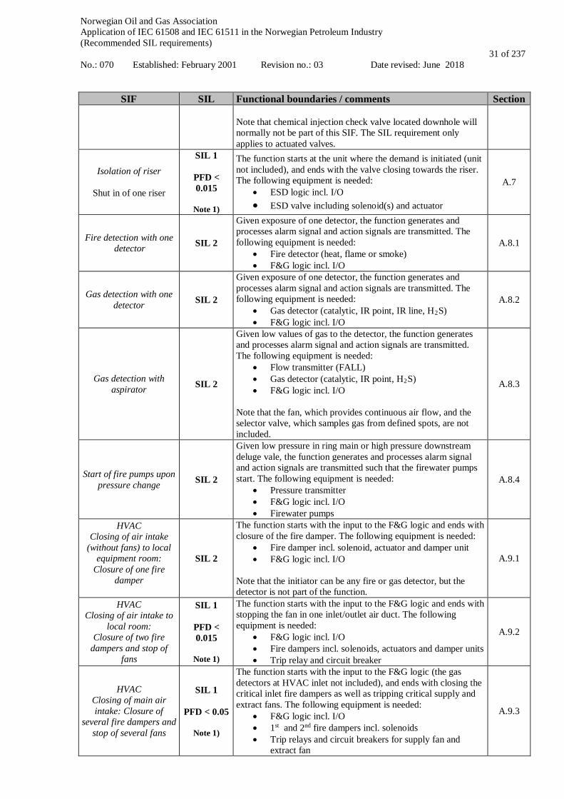
Norwegian Oil and Gas Association Application of IEC 61508 and IEC 61511 in the Norwegian Petroleum Industry (Recommended SIL requirements) No.: 070 Established: February 2001 Revision no.: 03 Date revised: June 2018
31 of 237
SIF SIL Functional boundaries / comments Section Note that chemical injection check valve located downhole will normally not be part of this SIF. The SIL requirement only applies to actuated valves.
Isolation of riser
Shut in of one riser
SIL 1
PFD < 0.015
Note 1)
The function starts at the unit where the demand is initiated (unit not included), and ends with the valve closing towards the riser. The following equipment is needed:
• ESD logic incl. I/O • ESD valve including solenoid(s) and actuator
A.7
Fire detection with one detector SIL 2
Given exposure of one detector, the function generates and processes alarm signal and action signals are transmitted. The following equipment is needed:
• Fire detector (heat, flame or smoke) • F&G logic incl. I/O
A.8.1
Gas detection with one detector SIL 2
Given exposure of one detector, the function generates and processes alarm signal and action signals are transmitted. The following equipment is needed:
• Gas detector (catalytic, IR point, IR line, H2S) • F&G logic incl. I/O
A.8.2
Gas detection with aspirator SIL 2
Given low values of gas to the detector, the function generates and processes alarm signal and action signals are transmitted. The following equipment is needed:
• Flow transmitter (FALL) • Gas detector (catalytic, IR point, H2S) • F&G logic incl. I/O
Note that the fan, which provides continuous air flow, and the selector valve, which samples gas from defined spots, are not included.
A.8.3
Start of fire pumps upon pressure change SIL 2
Given low pressure in ring main or high pressure downstream deluge vale, the function generates and processes alarm signal and action signals are transmitted such that the firewater pumps start. The following equipment is needed:
• Pressure transmitter • F&G logic incl. I/O • Firewater pumps
A.8.4
HVAC Closing of air intake
(without fans) to local equipment room:
Closure of one fire damper
SIL 2
The function starts with the input to the F&G logic and ends with closure of the fire damper. The following equipment is needed:
• Fire damper incl. solenoid, actuator and damper unit • F&G logic incl. I/O
Note that the initiator can be any fire or gas detector, but the detector is not part of the function.
A.9.1
HVAC Closing of air intake to
local room: Closure of two fire
dampers and stop of fans
SIL 1
PFD < 0.015
Note 1)
The function starts with the input to the F&G logic and ends with stopping the fan in one inlet/outlet air duct. The following equipment is needed:
• F&G logic incl. I/O • Fire dampers incl. solenoids, actuators and damper units • Trip relay and circuit breaker
A.9.2
HVAC Closing of main air intake: Closure of
several fire dampers and stop of several fans
SIL 1
PFD < 0.05
Note 1)
The function starts with the input to the F&G logic (the gas detectors at HVAC inlet not included), and ends with closing the critical inlet fire dampers as well as tripping critical supply and extract fans. The following equipment is needed:
• F&G logic incl. I/O • 1st and 2nd fire dampers incl. solenoids • Trip relays and circuit breakers for supply fan and
extract fan
A.9.3

Norwegian Oil and Gas Association Application of IEC 61508 and IEC 61511 in the Norwegian Petroleum Industry (Recommended SIL requirements) No.: 070 Established: February 2001 Revision no.: 03 Date revised: June 2018
32 of 237
SIF SIL Functional boundaries / comments Section Electrical isolation
Signal giving action
processed in F&G logic and electrical ignition
sources removed
SIL 2
The function starts at the unit initiating the demand (unit not included), and ends when the equipment is isolated. The following equipment is needed:
• F&G logic incl. I/O • Circuit breakers (3 off)
A.10
Release of firewater / Deluge
Fire water demand
signal processed in Fire & Gas logic, start of fire pump, and opening of
deluge-valve
SIL 2
The function starts at the unit initiating the demand (unit not included), and ends when there is flowing enough water through the deluge valve. The following equipment is needed:
• F&G logic • Firewater pumps • Deluge valve
The function is considered successful when a certain amount of water (l/min) flows through the deluge valve.
A.11.1
Release of Inergen
Opening of the Inergen release valve upon
signal from F&G logic
SIL 1
PFD < 0.02
Note 1)
The function starts with the input to the F&G logic (the F&G detectors not included), and ends with opening of the Inergen release valve. The following equipment is included:
• F&G logic incl. I/O • Inergen release valve incl. pilot/solenoid
A.11.2
Release of water mist
Opening of the water mist zone valve for
water distribution to the correct room/enclosure
SIL 1
PFD < 0.04
Note 1)
The function releases water mist for fire extinguishing in a dedicated room/enclosure upon signal. The following equipment is needed:
• F&G logic incl. I/O • Nitrogen release valve incl. pilot/solenoid • Pressure regulating valve • Water mist zone valve incl. pilot/solenoid
A.11.3
Water filling of Jacket
Opening of the isolation valve towards firewater distribution system upon
detection of LALL in jacket water reservoir tank (i.e. static header
tank)
SIL 1
PFD < 0.02
Note 1)
The function initiate filling of jacket water reservoir tank (i.e. static header tank) upon low level signal initiating opening of isolation valve towards firewater distribution system. The following equipment is needed:
• Level transmitter • F&G logic incl. I/O • Isolation valve on firewater connection line incl.
pilot/solenoid and actuator
A.11.4
Manual initiation of F&G/ESD functions
from field/CCR SIL 2
The SIL requirement applies to manual function initiated from field;
• Safety Node incl. I/O • Pushbutton
The function starts when the buttons have been pushed and ends when the output signal(s) from the safety system has been generated.
A.16
Start of ballast system for Initiation of rig re-
establishment
Opening of two ballast control valves and
starting of one of two ballast pumps
SIL 1
PFD < 0.02
Note 1)
The function starts when the operator has demanded emptying of one ballast water tank, and ends when emptying of that tank has been initiated. The following equipment is needed:
• Ballast node incl. I/O • Inlet valve incl. actuator, solenoid and valve • Ballast control pump (2 x 100%) incl. engine, generator
and motor • Discharge valve incl. actuator, solenoid and valve
A.12.1
Emergency stop of ballast system
SIL 1
PFD < 0.03
The function starts when the operator has operated the emergency stop pushbutton, and ends when the ballast pump motor has stopped and the inlet valve and discharge valve have closed. The following equipment is needed:
A.12.2
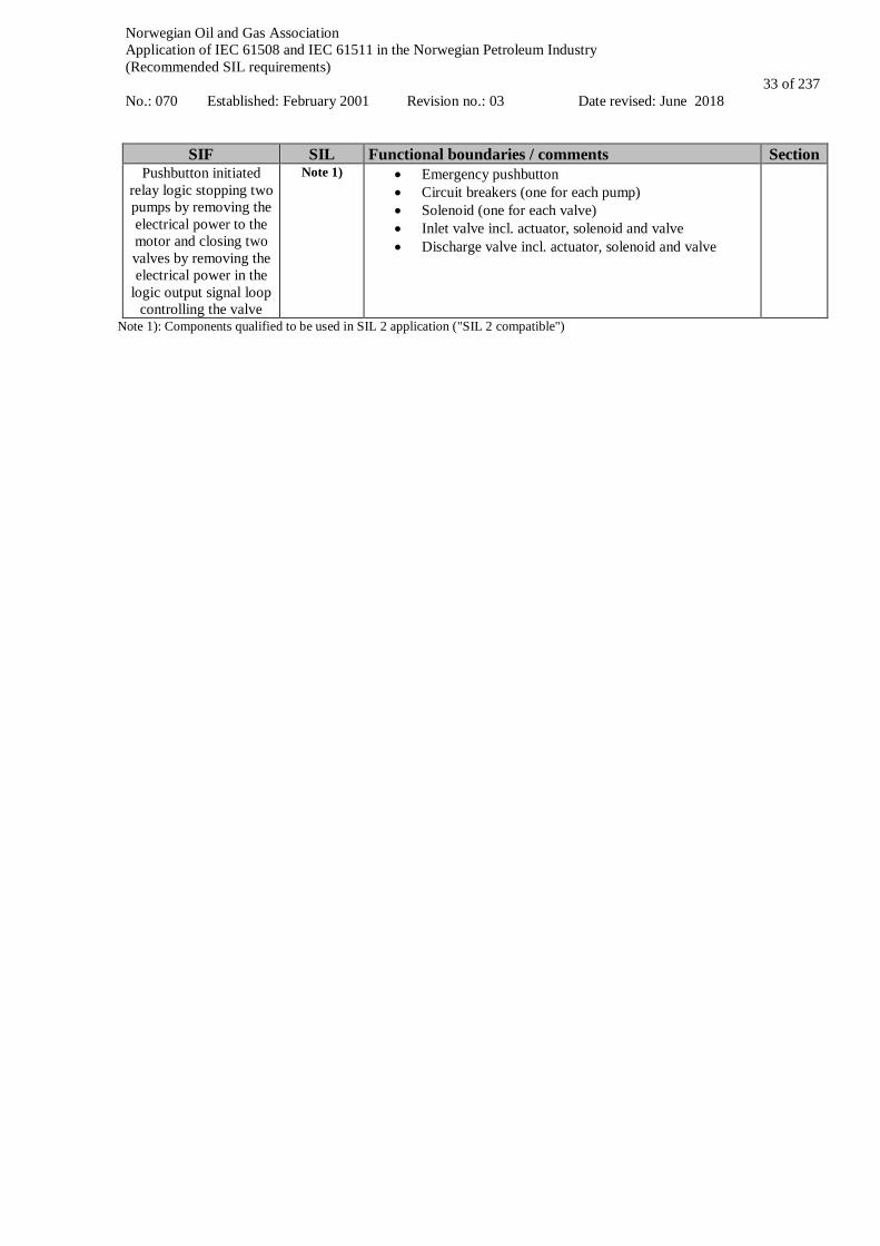
Norwegian Oil and Gas Association Application of IEC 61508 and IEC 61511 in the Norwegian Petroleum Industry (Recommended SIL requirements) No.: 070 Established: February 2001 Revision no.: 03 Date revised: June 2018
33 of 237
SIF SIL Functional boundaries / comments Section Pushbutton initiated
relay logic stopping two pumps by removing the electrical power to the motor and closing two valves by removing the electrical power in the
logic output signal loop controlling the valve
Note 1) • Emergency pushbutton • Circuit breakers (one for each pump) • Solenoid (one for each valve) • Inlet valve incl. actuator, solenoid and valve • Discharge valve incl. actuator, solenoid and valve
Note 1): Components qualified to be used in SIL 2 application ("SIL 2 compatible")
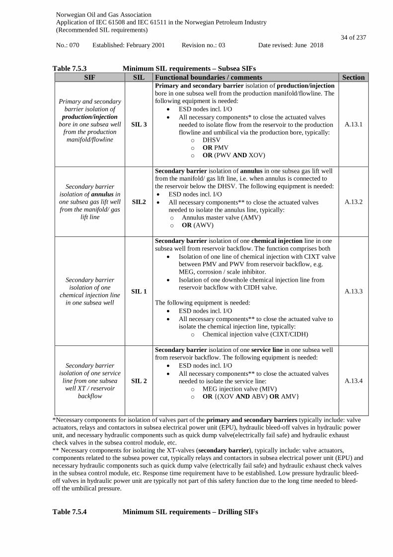
Norwegian Oil and Gas Association Application of IEC 61508 and IEC 61511 in the Norwegian Petroleum Industry (Recommended SIL requirements) No.: 070 Established: February 2001 Revision no.: 03 Date revised: June 2018
34 of 237
Table 7.5.3 Minimum SIL requirements – Subsea SIFs
SIF SIL Functional boundaries / comments Section
Primary and secondary barrier isolation of
production/injection bore in one subsea well
from the production manifold/flowline
SIL 3
Primary and secondary barrier isolation of production/injection bore in one subsea well from the production manifold/flowline. The following equipment is needed:
• ESD nodes incl. I/O • All necessary components* to close the actuated valves
needed to isolate flow from the reservoir to the production flowline and umbilical via the production bore, typically:
o DHSV o OR PMV o OR (PWV AND XOV)
A.13.1
Secondary barrier isolation of annulus in one subsea gas lift well from the manifold/ gas
lift line
SIL2
Secondary barrier isolation of annulus in one subsea gas lift well from the manifold/ gas lift line, i.e. when annulus is connected to the reservoir below the DHSV. The following equipment is needed: • ESD nodes incl. I/O • All necessary components** to close the actuated valves
needed to isolate the annulus line, typically: o Annulus master valve (AMV) o OR (AWV)
A.13.2
Secondary barrier isolation of one
chemical injection line in one subsea well
SIL 1
Secondary barrier isolation of one chemical injection line in one subsea well from reservoir backflow. The function comprises both
• Isolation of one line of chemical injection with CIXT valve between PMV and PWV from reservoir backflow, e.g. MEG, corrosion / scale inhibitor.
• Isolation of one downhole chemical injection line from reservoir backflow with CIDH valve.
The following equipment is needed:
• ESD nodes incl. I/O • All necessary components** to close the actuated valve to
isolate the chemical injection line, typically: o Chemical injection valve (CIXT/CIDH)
A.13.3
Secondary barrier isolation of one service line from one subsea well XT / reservoir
backflow
SIL 2
Secondary barrier isolation of one service line in one subsea well from reservoir backflow. The following equipment is needed:
• ESD nodes incl. I/O • All necessary components** to close the actuated valves
needed to isolate the service line: o MEG injection valve (MIV) o OR {(XOV AND ABV) OR AMV}
A.13.4
*Necessary components for isolation of valves part of the primary and secondary barriers typically include: valve actuators, relays and contactors in subsea electrical power unit (EPU), hydraulic bleed-off valves in hydraulic power unit, and necessary hydraulic components such as quick dump valve(electrically fail safe) and hydraulic exhaust check valves in the subsea control module, etc. ** Necessary components for isolating the XT-valves (secondary barrier), typically include: valve actuators, components related to the subsea power cut, typically relays and contactors in subsea electrical power unit (EPU) and necessary hydraulic components such as quick dump valve (electrically fail safe) and hydraulic exhaust check valves in the subsea control module, etc. Response time requirement have to be established. Low pressure hydraulic bleed-off valves in hydraulic power unit are typically not part of this safety function due to the long time needed to bleed-off the umbilical pressure. Table 7.5.4 Minimum SIL requirements – Drilling SIFs
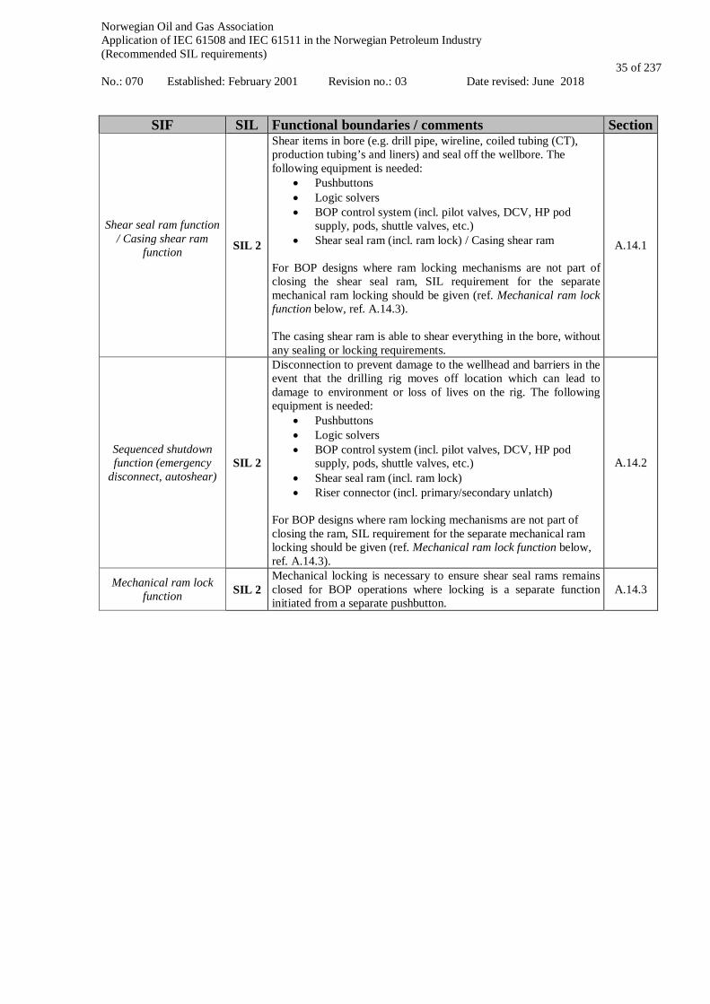
Norwegian Oil and Gas Association Application of IEC 61508 and IEC 61511 in the Norwegian Petroleum Industry (Recommended SIL requirements) No.: 070 Established: February 2001 Revision no.: 03 Date revised: June 2018
35 of 237
SIF SIL Functional boundaries / comments Section
Shear seal ram function / Casing shear ram
function
SIL 2
Shear items in bore (e.g. drill pipe, wireline, coiled tubing (CT), production tubing’s and liners) and seal off the wellbore. The following equipment is needed:
• Pushbuttons • Logic solvers • BOP control system (incl. pilot valves, DCV, HP pod
supply, pods, shuttle valves, etc.) • Shear seal ram (incl. ram lock) / Casing shear ram
For BOP designs where ram locking mechanisms are not part of closing the shear seal ram, SIL requirement for the separate mechanical ram locking should be given (ref. Mechanical ram lock function below, ref. A.14.3). The casing shear ram is able to shear everything in the bore, without any sealing or locking requirements.
A.14.1
Sequenced shutdown function (emergency
disconnect, autoshear) SIL 2
Disconnection to prevent damage to the wellhead and barriers in the event that the drilling rig moves off location which can lead to damage to environment or loss of lives on the rig. The following equipment is needed:
• Pushbuttons • Logic solvers • BOP control system (incl. pilot valves, DCV, HP pod
supply, pods, shuttle valves, etc.) • Shear seal ram (incl. ram lock) • Riser connector (incl. primary/secondary unlatch)
For BOP designs where ram locking mechanisms are not part of closing the ram, SIL requirement for the separate mechanical ram locking should be given (ref. Mechanical ram lock function below, ref. A.14.3).
A.14.2
Mechanical ram lock function SIL 2
Mechanical locking is necessary to ensure shear seal rams remains closed for BOP operations where locking is a separate function initiated from a separate pushbutton.
A.14.3
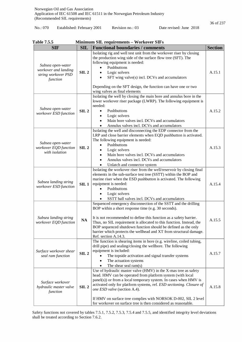
Norwegian Oil and Gas Association Application of IEC 61508 and IEC 61511 in the Norwegian Petroleum Industry (Recommended SIL requirements) No.: 070 Established: February 2001 Revision no.: 03 Date revised: June 2018
36 of 237
Table 7.5.5 Minimum SIL requirements – Workover SIFs
SIF SIL Functional boundaries / comments Section
Subsea open-water workover and landing string workover PSD
function
SIL 2
Isolating rig and well test unit from the workover riser by closing the production wing side of the surface flow tree (SFT). The following equipment is needed:
• Pushbuttons • Logic solvers • SFT wing valve(s) incl. DCVs and accumulators
Depending on the SFT design, the function can have one or two wing valves as final elements
A.15.1
Subsea open-water workover ESD function SIL 2
Isolating the well by closing the main bore and annulus bore in the lower workover riser package (LWRP). The following equipment is needed:
• Pushbuttons • Logic solvers • Main bore valves incl. DCVs and accumulators • Annulus valves incl. DCVs and accumulators
A.15.2
Subsea open-water workover EQD function
with isolation SIL 2
Isolating the well and disconnecting the EDP connector from the LRP and close barrier elements when EQD pushbutton is activated. The following equipment is needed:
• Pushbuttons • Logic solvers • Main bore valves incl. DCVs and accumulators • Annulus valves incl. DCVs and accumulators • Unlatch and connector system
A.15.3
Subsea landing string workover ESD function SIL 1
Isolating the workover riser from the well/reservoir by closing final elements in the sub-surface test tree (SSTT) within the BOP and marine riser when the ESD pushbutton is activated. The following equipment is needed:
• Pushbuttons • Logic solvers • SSTT ball valves incl. DCVs and accumulators
A.15.4
Subsea landing string workover EQD function NA
Sequenced emergency disconnection of the SSTT and the drilling BOP within a short response time (e.g. 30 seconds). It is not recommended to define this function as a safety barrier. Thus, no SIL requirement is allocated to this function. Instead, the BOP sequenced shutdown function should be defined as the only barrier which protects the wellhead and XT from structural damage. Ref. section A.14.3.
A.15.5
Surface workover shear seal ram function SIL 2
The function is shearing items in bore (e.g. wireline, coiled tubing, drill pipe) and sealing/closing the wellbore. The following equipment is included:
• The topside activation and signal transfer systems • The actuation systems • The shear seal ram(s)
A.15.7
Surface workover hydraulic master valve
function SIL 2
Use of hydraulic master valve (HMV) in the X-mas tree as safety head. HMV can be operated from platform system (with local panel(s)) or from a local temporary system. In cases when HMV is activated only for platform systems, ref. ESD sectioning. Closure of one ESD valve (section A.4). If HMV on surface tree complies with NORSOK D-002, SIL 2 level for workover on surface tree is then considered as reasonable.
A.15.8
Safety functions not covered by tables 7.5.1, 7.5.2, 7.5.3, 7.5.4 and 7.5.5, and identified integrity level deviations shall be treated according to Section 7.6.2.

Norwegian Oil and Gas Association Application of IEC 61508 and IEC 61511 in the Norwegian Petroleum Industry (Recommended SIL requirements) No.: 070 Established: February 2001 Revision no.: 03 Date revised: June 2018
37 of 237
7.6 Handling of deviations from the minimum SIL requirements
7.6.1 Identification of deviations from the minimum SIL table As discussed in section 7.1, the objective of the minimum SIL/PFD table is to cover the most common safety functions. However, deviations from this table will occur. In the context of the minimum SIL/PFD requirements, the following cases are most relevant to consider:
• A safety function not covered by Tables 7.5.1, 7.5.2, 7.5.3, 7.5.4 and 7.5.5. Such functions may result from hazards requiring instrumented safety functions other than those defined as conventional design according to ISO 10418/API RPI 14C, other relevant standards or those described in this guideline. This would typically be HIPPS as a replacement for PSV capacity, instrumented protection instead of full flow PSV capacity, safety interlock systems, pipeline protection systems, unproven technology, etc.
• An integrity level deviation, i.e. an instrumented safety function as described in the minimum SIL table has been identified, but particular conditions imply a different integrity level requirement. Such a requirement may arise from:
o a special consideration related to the frequency of the associated hazard, e.g. a high demand rate on a particular safety function is foreseen or experienced. Identification
of a high demand rate may be done in the design phase, e.g. during HAZOP, but would normally result from operational experience (in which case it according to ISO terms, will actually represent a non-conformity, ref. section 4.1). A very high demand rate on a safety function would often represent an operational problem with respect to production availability and as such initiate alternative solutions and/or re-design. High demand SIFs shall in accordance with IEC 61511 be subject to PFH calculations and are not covered by the PFD requirements set forth by the minimum SIL Table2 7.5.1, 7.5.2, 7.5.3, 7.5.4 and 7.5.5.
a high total risk is foreseen for a particular safety function, e.g. a very large number of risers on a platform may result in, a stricter SIL requirement for the function “isolation of riser”..
o a special consideration related to the consequences of the associated hazard, e.g. due to concept specific aspects concerning layout, process conditions (pressures, temperatures, fluid characteristics), manning, escalation potential, etc. may indicate a higher SIL requirement than specified in Section 7.5.
The application of analysis techniques like HAZOP, HAZID, SAT and design reviews, does not give any guarantee as to whether all potential safety functions and potential deviations from the minimum SIL table are actually identified. However, in order to minimise the likelihood of disregarding any such functions, the important point is to ensure a consistent approach towards hazard identification and identification of all SIFs. If ISO 13702 is properly fulfilled, the methodology described therein facilitates a consistent approach towards such identification. Reference is also made to NORSOK standard Z013 (Risk and Emergency Preparedness Analysis) and ISO 17776 with respect to guidance concerning hazard identification and assessment.
7.6.2 Determination of SIL for safety functions where section 7.5 is not applicable Relevant requirements are given in IEC 61511-1, cl. 8.2.1 and cl. 9. IEC 61511-3 and IEC 61508-5 contain several risk based methods for establishing safety integrity levels. Two of the most prevailing methods are risk graph and layers of protection analysis (LOPA). LOPA is a semi-quantitative method, often considered more rigorous and provides more substantiated conclusions compared to risk graph. Both methods have some challenges, e.g. limited application for global safety functions, lack of calibration against an overall risk acceptance criteria and the fact that LOPA studies often omit the possibility of dependencies between risk reduction measures. Note that according to IEC 61511-3, Annex F, the intention is that only truly independent layers of protection are to be fully credited in a LOPA. Regardless of which method is chosen for determination of SIL, the process for arriving at the specific integrity level requirement shall be properly documented. Important assumptions and prerequisites for determining the SIL shall be followed up in the operational phase (ref. chapter 10) and any deviations from these assumptions shall be assessed and actions taken is required, e.g. a very high demand rate in operation as compared to the assumed demand rate during engineering might induce requirements for additional risk reducing measures.
Norwegian Oil and Gas Association Application of IEC 61508 and IEC 61511 in the Norwegian Petroleum Industry (Recommended SIL requirements) No.: 070 Established: February 2001 Revision no.: 03 Date revised: June 2018
38 of 237
7.7 Safety Requirements Specification Relevant requirements are given in IEC 61511-1, cl. 10. The Safety Requirements Specification (SRS) shall be established for the safety-instrumented systems. The SRS is initially derived from the allocation of SIFs and from those requirements identified during safety planning. The SRS shall provide a basis for design, and the document shall be further developed and maintained through all lifecycle phases of the SIS. As discussed in chapter 5, IEC 61511 and IEC 61508 have a focus on risk reduction related to the safety-instrumented systems. However, all types of barriers and barrier elements shall be addressed in the barrier strategy document for the facility (ref. section 5.2). Hence, the SRS will often be referred to in the barrier strategy. The SRS is the main document regarding SIS safety related requirements/parameters and shall include reliability/PFD targets as well as assumed demands rates and spurious trip rates. The SRS shall focus on the most critical requirements (ref. IEC 61511-1, cl. 10.3.2) and should provide such information in a short and concise manner. Where the SRS is not the main source of information, references to other documents and sources of information addressing detailed functional and technical requirements should be given to avoid any inconsistencies. Replication of requirements should be avoided. As part of the SRS development, application program safety requirements shall be developed for the SIS. The application program safety requirements shall be contained either as part of the main SRS or in a separate document. Issues that shall be considered when developing the SIS safety requirements are further described in IEC 61511-1, cl. 10.3 and cl. 12.2. Appendix E in this guideline includes a proposed structure and list of content for the SRS, and for the application program safety requirements.
Norwegian Oil and Gas Association Application of IEC 61508 and IEC 61511 in the Norwegian Petroleum Industry (Recommended SIL requirements) No.: 070 Established: February 2001 Revision no.: 03 Date revised: June 2018
39 of 237
8 SIS Design and Engineering
8.1 Objectives This section covers the SIS realisation phase, i.e. box 4 in Figure 2.2. Of special relevance to the realisation phase are IEC 61511-1, cl. 9, 11, 12 and 13. The objective of the realisation phase is to design one or multiple SIS in order to implement the SIFs and meet the integrity requirements as specified in the SRS. Realisation of safety related systems other than SIS, is not covered by IEC 61511, and is therefore not included in this guideline. SIS design and engineering as described in IEC 61511-1, cl. 11 includes a number of requirements, e.g. concerning independence, system behaviour on detection of a fault, hardware fault tolerance, selection of devices, interfaces, maintenance or testing design requirements and requirements concerning quantification of random hardware failures. This chapter does not cover all these topics, but a selection based on identified industry needs.
8.2 Input The SRS will provide the design basis and vendors and subcontractors shall verify that their products are suitable for use in safety applications in agreement with the SRS or as stated in the contract, ref. IEC 61511-1, cl. 11.5. Operational, functional and environmental limitations related to different subsystems/components which do not satisfy the SRS requirements shall be identified and brought to the attention of the system integrator and customer.
8.3 SIL Requirements For safety functions implemented through SIS technology, there are three main types of requirements that shall be fulfilled in order to achieve a given SIL: • A quantitative requirement, expressed as a probability of failure on demand (PFD) or alternatively as the
probability of a dangerous failure per hour (PFH), according to Table 8.1; • A qualitative requirement, expressed in terms of requirements to the hardware fault tolerance on the SIS
subsystems constituting the safety function, ref. Tables 8.2 –8.4; • Management of functional safety (ref. chapter 5), including requirements concerning which techniques and
measures should be used to avoid and control systematic faults. Below, these three types of requirements are briefly discussed. See also IEC 61511-1, cl. 9.2 and cl. 11.4.
8.3.1 Quantitative requirements IEC 61511 applies both to systems operating ‘on demand’ as well as to systems operating continuously in order to maintain a safe state. An example of a demand mode system would be the ESD system, whereas the process control system for an unstable process like an exothermic reactor will represent a continuous mode system. In Table 8.1 the relationship between the SIL and the required failure probability is shown (ref. IEC 61511-1, Table 4 and Table 5).

Norwegian Oil and Gas Association Application of IEC 61508 and IEC 61511 in the Norwegian Petroleum Industry (Recommended SIL requirements) No.: 070 Established: February 2001 Revision no.: 03 Date revised: June 2018
40 of 237
Table 8.1 Safety integrity levels for safety functions operating on demand or in a continuous /
high demand mode Safety Integrity Level Demand Mode of Operation
(average probability of failure to perform its
design function on demand - PFD)
Continuous / High Demand Mode of Operation
(probability of a dangerous failure per
hour - PFH) 4 ≥ 10-5 to < 10-4 ≥ 10-9 to < 10-8 3 ≥ 10-4 to < 10-3 ≥ 10-8 to < 10-7 2 ≥ 10-3 to < 10-2 ≥ 10-7 to < 10-6 1 ≥ 10-2 to < 10-1 ≥ 10-6 to < 10-5
It should be noted that the PFD requirement applies to a complete function, i.e. the field sensor, the logic solver and the final element e.g. a valve. A component may be certified for a particular SIL application, but such a certificate constitutes only part of the verification effort, since the required failure probability from Table 8.1 shall be verified for the complete function.
8.3.2 Architectural constraints The highest safety integrity level that can be claimed for a safety function is limited by architectural constraints as described in IEC 61508-2, cl. 7.4 and IEC 61511-1, cl. 11.4. Fulfilment of architectural constraints can be achieved by implementing one of two possible routes (IEC 61508-2, cl. 7.4.4):
• Route 1H based on hardware fault tolerance (HFT) and safe failure fraction (SFF) concepts • Route 2H based on reliability data from field feedback on similar devices, increased confidence levels and
HFT for specified safety integrity levels. Route 1H will apply for development of new technology where no field experience is available. Route 2H requires that the equipment is developed in compliance with IEC 61508 (ref. Figure 2.1) or is documented to be prior use (ref. chapter 8.4.2). Route 2H will typically apply for integrators and end users, where relevant field experience from application of the selected equipment is available. Architectural requirements according to IEC 61508 (Route 1H) Architectural constraints on hardware safety integrity are given in terms of three parameters • the hardware fault tolerance of the subsystem (HFT). Each SIF shall have a minimum hardware fault tolerance
(HFT). When the SIS can be split into separate SIS subsystems (e.g. sensors, logic solvers and final elements) the HFT should be assigned at the SIS subsystem level. As an example a subsystem with HFT=1 (like for 1oo2 voting), can withstand one failure and still function.;
• the safe failure fraction (SFF), i.e. the fraction of failures which can be considered “safe” because they are detected by diagnostic tests or do not cause loss of the safety function, ref. appendix D;
• whether the subsystem is of type A or type B. For type A subsystems all possible failure modes can be determined for all constituent components (e.g. a solenoid), whereas for type B subsystems the behaviour under fault conditions cannot be completely determined for at least one component (e.g. a logic solver).
Further details are given in IEC 61508-2, cl. 7.4.4.2. The architectural requirements for different safety integrity levels are given in Table 8.2 and 8.3 below. Observe that in the 2010 version of IEC 61508 it is explicitly stated (IEC 61508-4, cl. 3.6.13 –14) that failures not being part of or having no effect on a safety function shall not be included in calculation of safe failure fraction (SFF). This may result in lower SFFs when using the 2010 version of IEC 61508 as compared to the 2002 version, since no-effect failures may previously have been credited as safe.

Norwegian Oil and Gas Association Application of IEC 61508 and IEC 61511 in the Norwegian Petroleum Industry (Recommended SIL requirements) No.: 070 Established: February 2001 Revision no.: 03 Date revised: June 2018
41 of 237
Table 8.2 Hardware safety integrity: architectural constraints on type A safety-related subsystems (IEC 61508-2, Table 2)
Safe failure fraction (SFF)
Hardware fault tolerance
0 1 2 < 60 % SIL1 SIL2 SIL3
60 % - 90 % SIL2 SIL3 SIL4 90 % - 99 % SIL3 SIL4 SIL4
> 99 % SIL3 SIL4 SIL4
Table 8.3 Hardware safety integrity: architectural constraints on type B safety-related subsystems (IEC 61508-2, Table 3)
Safe failure fraction (SFF)
Hardware fault tolerance
0 1 2 < 60 % not allowed SIL1 SIL2
60 % - 90 % SIL1 SIL2 SIL3 90 % - 99 % SIL2 SIL3 SIL4
> 99 % SIL3 SIL4 SIL4 NOTES: 1. This document considers programmable logic solvers to be of type B components according to the standard; 2. It should be noted that the ‘hardware safety integrity’ provides the maximum SIL that is permitted to be claimed even though,
in some cases, a higher SIL could derive from solely mathematical reliability calculations (ref. IEC 61508-2, cl. 7.4.4.1.1). Hardware fault tolerance according to IEC 61511 (Route 2H) If the equipment is developed in compliance with IEC 61508 (ref. Figure 2.1) or is documented to be prior use (ref. chapter 8.4.2), route 2H can be applied. Then, the minimum HFT shall be in accordance with Table 8.4 below (ref. IEC 61511-1, Table 6) Table 8.4 Minimum HFT requirements according to SIL (ref. Table 6 in IEC 61511-1)
SIL Minimum required HFT 1 (any mode) 0 2 (low demand mode) 0 2 (continuous mode) 1 3 (high demand mode or continuous mode) 1 4 (any mode) 2
Further explanation is given in IEC 61511-1, cl. 11.4.
8.3.3 Avoidance and control of systematic faults Systematic faults are faults in hardware and software introduced during specification, design, operation or maintenance/testing, which may result in a failure of the safety function under certain conditions (e.g. for particular input signal states). In IEC 61508/61511 such failures are, unlike random hardware failures, not quantified. Rather, IEC 61511 and IEC 61508 require that certain measures and techniques are adopted to avoid and control such failures. These measures and techniques shall be adopted during the design phase and are graded according to the SIL requirements. Details on these methods are given in IEC 61508-2 for hardware and IEC 61508-3 for software. In a recent report (SINTEF, 2015) results from a review of some 12 000 maintenance malfunction notifications are presented. This work indicates that systematic failures tend to occur much more frequently than predicted during design, and the report points to several potential improvement areas for avoidance and control of systematic failures. Some general examples of such improvement areas include:
• Ensure that that the equipment is fit for its intended use - avoid "copy and paste" solutions; • Avoid unnecessary complexity;

Norwegian Oil and Gas Association Application of IEC 61508 and IEC 61511 in the Norwegian Petroleum Industry (Recommended SIL requirements) No.: 070 Established: February 2001 Revision no.: 03 Date revised: June 2018
42 of 237
• Improve procedures and routines for FAT, commissioning and installation. A significant number of failures that should have been removed during acceptance testing and commissioning are experienced;
• Improve experience feedback from end users to manufacturers; • Perform more frequent and better root cause analysis of underlying failure causes.
8.4 Proven in use and Prior use The concepts of proven in use and prior use may look similar, but they have some important differences. Proven in use is a concept introduced in IEC 61508-2 as an alternative route to demonstrate avoidance and control of systematic failures, and applies to manufacturers of devices. Prior use is a concept introduced in IEC 61511-1 for end users to qualify devices not developed according to IEC 61508.
8.4.1 Proven in use The requirements to fulfil proven in use are given in IEC 61508-2, cl. 7.4.10 and represents one out of three options for demonstrating avoidance and control of systematic failures of a device. The demonstration covers two tasks:
(i) to document that the dangerous failure rate in operation does not exceed the dangerous failure rate that has been claimed by the manufacturer, and
(ii) to demonstrate that the contribution of systematic faults is low enough to avoid that the SIL requirement is exceeded.
Task (i) and (ii) indicate that a careful review of all reported failures shall be performed. It also requires that the observation period should be sufficient to gain the necessary confidence about the result. For some suggested criteria concerning how to document proven in use, reference is made to IEC 61508-7 (Annex B.5.4, Annex C.2.10.1 and Annex D)
8.4.2 Prior use The main intent of the prior use evaluation is to gather evidence that the dangerous systematic failures have been reduced to a sufficiently low level compared to the required safety integrity (ref. IEC 61511-1, cl. 11.5.3). IEC 61511 focuses primarily on system integration but also gives restrictions on the selection of devices. Prior use in IEC 61511-1, cl. 11.5.3, is one out of several restrictions (see also cl. 11.5.4–11.5.6) that applies to devices not developed according to IEC 61508. The demonstration of prior use means that the end user develops an evidence of suitability that includes the following information:
i. Identification of the manufacturer’s quality, management, and configuration management systems; ii. Precise identification and specification of the devices;
iii. Data that identifies the performance of the device for similar operating profiles (e.g., failure rates, demand rates);
iv. An evaluation of the volume of the operating experience in light of statistical confidence.
For field devices the user’s list of approved equipment can be used to support claims of experience in operation/prior use (ref. IEC 61511-1, cl. 11.5.3.2). IEC 61511 does not give any specific requirements to the volume of operating experience. A note states that "the amount of operational experience to gain credible statistical reliability data is typically much higher compared to the operational experience necessary to get evidence of prior use." However, this statement is somewhat confusing as the evidence of suitability for demonstrating prior use also points to statistical confidence (point iv.), which generally requires a significant amount of operational data. For example, in order to obtain 95% confidence that a failure rate is below 1E-6 per hour, some three million hours of accumulated operating time will be required. This is further discussed in the PDS data handbook (section 3.7) and also in Appendix F in this guideline. In the absence of specific requirements concerning the volume of operating experience reference is often made to the requirements for field experience as suggested in IEC 61508-7, cl. B.5.4:
• Unchanged specification; • 10 systems in different applications;
Norwegian Oil and Gas Association Application of IEC 61508 and IEC 61511 in the Norwegian Petroleum Industry (Recommended SIL requirements) No.: 070 Established: February 2001 Revision no.: 03 Date revised: June 2018
43 of 237
• 100 000 operating hours and at least one year of service history. As seen from the above discussion of statistical confidence, 100 000 operating hours will on its own not be sufficient to demonstrate the main intent of prior use, i.e. "to gather evidence that the dangerous systematic failures have been reduced to a sufficiently low level compared to the required safety integrity". Additional analysis work (e.g. FMEDA) and/or other documentation (ref. point i. – iii.) will therefore be required to develop evidence of suitability. As part of this documentation, end-user or integrator acting on end-user’s behalf, shall make a qualitative assessment and provide documentary evidence that safety devices, including PE logic solvers, can be selected based on “prior use”. Such an assessment may e.g. include:
• A judgement of the information provided by the manufacturer, such as the safety manual/SAR. • Establishing operating references, ref., item iii) and iv).
o Make judgement on failure data and verify if quantitative and architectural requirements can be achieved.
• For programmable field devices (sensors and final elements), a judgement on prior use should be based on FPL, ref. IEC61511, cl. 11.5.4
• For programmable logic solver (e.g., PSD nodes), a judgement on prior use should be based on LVL, ref., IEC 61511-1, cl. 11.5.5.5–11.5.5.6.
When the applications are programmed using a FVL, the programmable electronic (PE) device shall be in accordance with IEC 61508-2:2010 and IEC 61508-3:2010, ref. IEC 61511-1, cl. 11.5.6. It is important to note that the recommendations regarding observation period for systems operating in the low demand mode assumes regularly activations (i.e. tests and/or actual demands) to confirm the ability of the devices to function on demand. An observation period that does not include a suitable number of activations is not regarded as valid for demonstrating fault free operation. Reference is also made to section 8.5 concerning requirements to failure data.
8.5 Requirements to Failure Data
8.5.1 Objective The objective of this section is to ensure high quality of the failure data used in PFD calculations. The use of failure data is discussed in IEC 61511-1, cl. 11.9.3 and 11.9.4. Other relevant standards and references with respect to collection and application of failure data include ISO 14224, ISO 20815 and ISO/TR 12489. Major discrepancies between equipment failure rates from different data sources are often observed. It is therefore important to provide some guidance related to which type of failure data and data sources to apply in the SIL calculations.
8.5.2 SIS data sources IEC 61511-1 states that the reliability data used when quantifying the effect of random failures shall be credible, traceable, documented and justified. It is further stated that the reliability data can be based on existing field feedback on similar devices used in a similar operating environment. This may include historic data collected by the operator, manufacturer/vendor data derived from data collected on devices, data from generic or equipment specific reliability databases, etc. SIS failure data can be obtained from different sources (ref. categorisation scheme in ISO 14224, Annex D.5): Generic data
• are often based on operational experience from same or similar applications and typically cover several installations and several comparable equipment types (e.g. a population of level transmitters with different measuring principles);
• As such, generic data reflect some kind of average expected field performance for the equipment type under consideration;
• Examples of such data sources for SIS equipment are the OREDA handbooks and the PDS data handbook;

Norwegian Oil and Gas Association Application of IEC 61508 and IEC 61511 in the Norwegian Petroleum Industry (Recommended SIL requirements) No.: 070 Established: February 2001 Revision no.: 03 Date revised: June 2018
44 of 237
• Care should be taken to use data as similar as possible to the type of component and the operating environment of the system to be designed (see also Annex E.2 in ISO 20815);
• Generic data can sometimes be made more specific by narrowing down the ‘filtering’ of data towards installation, component type or other attributes. Sufficient statistical confidence in the data may however become a challenge;
• Generic data are often used in early project phases due to immature design and limited information about the selected equipment. As the design progresses, efforts should be made to apply reliability data reflective of the specific operating environment and the equipment to be applied, however keeping in mind the aspects of statistical confidence and proper documentation of the applied failure rates.
Operator / company specific data • PSA (Management Regulations, section 19) requires that the operators shall collect, process and use reliability
data to ensure that the performance of the barrier elements is in accordance with requirements (e.g. in the SRS) • Many companies have their own "preferred" set of data that may typically be based on collection of reliability
data from installations operated by the company and/or the company's own interpretation of different data sources. Such operator/company specific data may be part of an industrial cooperation generic database (like the OREDA JIP database), or purely own company data
• The advantage of company specific databases may be that they better reflect company specific operational philosophies and conditions. On the other hand, the statistical confidence in the data may become poorer when fewer installations are part of the data basis.
Manufacturer data • These are data prepared by a particular manufacturer for a specific product. Such data may be based on:
o field return data from installations where the product has been in operation. A general problem is that manufacturers often do not get failure reports back from the end users. It should therefore be kept in mind that manufacturers are only able to collect valid failure data in close collaboration with the operators. Failure data from manufacturers should therefore be carefully documented with respect to how they are obtained and to which extent they represent an exhaustive count of all failures occurred (possibility of underestimation).
o an assessment made by a third part or the manufacturer himself, e.g. based on a Failure Mode Effects and Diagnostic Analysis (FMEDA), comparison with similar products / other generic data sources or a combination of different approaches. Care should be made using data derived from FMEDA as they are often not calibrated against specific oil and gas operating conditions. Therefore, a recalibration may be necessary or the FMEDA data should be compared with available historic field experience data.
o laboratory testing, e.g. accelerated life testing, typically for new technology/products. If the experience data is based on tests in the laboratory, the tests should reflect the relevant operating conditions and demands of the actual safety function. It should also be ensured that all relevant failure modes are revealed during such tests. If "B10 numbers1" are applied for low demand calculations it shall be documented that the cyclic testing covers all relevant failure modes.
• An increasing trend towards third party product certificates can be observed. Such certificate data needs to be thoroughly documented, both with respect to how the failure rates are obtained as well as requirements for use and assumptions relevant for the certificate to be valid.
Equipment specific failure rates claimed by manufacturers are often significantly lower than the failure rates that are found in generic data sources such as the OREDA and PDS data handbooks. One reason for this may be that manufacturer data does not include systematic failures resulting from operating, or site specific conditions that are beyond the control of the manufacturer. While the intention in IEC 61508 and IEC 61511 is that certain measures and techniques shall be adopted to avoid and control systematic failures, the gap between claimed and observed failure rates are often too big to be ignored or to simply be explained by unquantified systematic failures. This statement is further supported by the fact that some manufacturer data as well as data from certificates are often not substantiated (or qualified) in a satisfying way (e.g. by historic field experience).
1 The “B10 number” is based on cyclic testing of a device and is a measure of time where 10% of a population of devices should have failed (see e.g. ISO 13849, Appendix A). The B10 number is based on the assumption that all random failures are due to premature wear-out mechanisms. For low-demand applications such as a shutdown valve there will be failure modes such as stuck in open position due to seldom use. Such failures will not be revealed by a B10 cycle test.

Norwegian Oil and Gas Association Application of IEC 61508 and IEC 61511 in the Norwegian Petroleum Industry (Recommended SIL requirements) No.: 070 Established: February 2001 Revision no.: 03 Date revised: June 2018
45 of 237
8.5.3 Achieving the specified risk reduction - requirements to the applied SIS data A fundamental concept in both IEC 61508 and IEC 61511 is the notion of risk reduction; the higher the SIL, the greater the risk reduction that can be achieved. . In this guideline we will therefore promote the importance of applying realistic failure data in the design calculations, since too optimistic failure rates may suggest a higher risk reduction than what is obtainable in operation. In other words; the predicted risk reduction, calculated for a SIF in the design phase, should to the degree possible reflect the actual risk reduction that may be experienced in the operational phase. It is therefore recommended that failure data is based on historic field experience are used as a basis for PFD calculations. The failure data in the PDS Data Handbook represents the collected experience in the area of reliability of safety instrumented systems, mainly from the Norwegian oil and gas industry, and may be used as one point of reference. If more optimistic failure data than these are applied, sufficient documentation should be provided. Manufacturers shall provide a justification that the delivered equipment complies with the reliability requirements. This justification should address the specific equipment which is delivered. For new technology or modified equipment there may be no applicable operational experience. In such cases failure rate estimates should be based on FMEDA and generic component failure rates adjusted to the best judgement of an expert team to reflect the site specific application and operating environment. When developing new hardware (according to IEC 61508) PFD and SFF calculations may be based on well recognized electronic reliability data sources such as RIAC HDBK 217Plus, IEC TR62380, Siemens SN29500 or Telecordia SR-332. It is also strongly recommended to perform a full Technology Qualification study including the requirements from IEC 61508/61511 for new equipment. See also ISO 20815 where technology qualification issues related to reliability are addressed. Assuming that the failure rates established by the manufacturers are lower than the historic failure rates used in the requirements phase, there is no need to update the SIL calculations with manufacturer data, since system SIL compliance is already demonstrated. In any case, it is not recommended to use manufacturer data for extending proof test intervals. For this purpose reliability data collected during actual operation of the plant should be used as further described in chapter 10 concerning follow-up of SIS in operation. The above recommendation does not exclude manufacturer data from being used in PFD calculations. Manufacturers may have very good systems and procedures for collecting relevant field return data. The quality of their data may therefore exceed the quality of generic data as the manufacturer data will benefit from being targeted towards a specific product. However, manufacturer data, if used in PFD calculations, should be thoroughly qualified and documented in a traceable manner. If failure modes or causes are excluded from the underlying reliability data collected in the field, this should be highlighted and sufficient arguments why this is done given. When evaluating if data based on field experience are qualified for use in PFD calculations, the following issues should be considered (see also Annex E.2 in ISO 20815): Data collection approach
• The method for data collection should preferably be based on approved data classification standards (ISO 14224, ISO 20815).
• Collection of data should take place over the useful life of the equipment. Burn-in failures and startup/commissioning failures should be considered separately, as they will impose an additional risk during early operation, but may not be representative for the subsequent operational phase. Collection of manufacturer data should extend beyond the product guarantee period.
• For the specified population all failures should be registered and accounted for, e.g.: o dangerous failures revealed between tests (e.g. by a real demand/activation); o equipment failures repaired at site without sending the equipment back to the manufacturer; o failures repaired "on the spot" without requiring intervention by maintenance team; o failures repaired immediately by maintenance service provider performing routine checks;
• Failures should be registered "as found" and tests should be performed with equipment in "as is" condition, e.g. do not perform cleaning and lubrication prior to testing.
Detailing level
• The collected data should be detailed enough for proper data classification to be performed (including equipment type, make, relevant process conditions, etc.). Equipment notifications are normally registered by first line O&M personnel and should therefore be reviewed and if necessary corrected before the data is used in reliability analysis. Correct specification of failure mode, failure cause and detection method is essential in order to enable the failures to be classified as dangerous undetected (DU), dangerous detected (DD) or Safe. ((SIS failure mode classification is included in Table 6 in ISO 14224).
Norwegian Oil and Gas Association Application of IEC 61508 and IEC 61511 in the Norwegian Petroleum Industry (Recommended SIL requirements) No.: 070 Established: February 2001 Revision no.: 03 Date revised: June 2018
46 of 237
• The safety function of the equipment under consideration shall be known, including the safe state for the function and whether the final element is normally energised (NE) or normally de-energised (NDE).
• The operating environment under which the data has been collected should be specified (both internal and external). In case of major differences, the effect of these conditions should be assessed (and correction factors considered).
• The actual operating time of the equipment under consideration shall be known as well as details concerning proof testing of the equipment (frequency, coverage).
• Equipment boundaries, i.e. components included /excluded in the reported data shall be specified.
All failure causes with a potential to result in a critical failure should be included in the reported data. Consequently, systematic failures should not be excluded, but may be treated separately in addition to random hardware failures. The objective here is to ensure that the data used in SIL calculations as far as possible reflects conditions that may be experienced in operation. Common cause failures (CCF) should also be registered when collecting historic reliability data (SINTEF, 2015). Failures should however be registered either as independent failures or as one CCF since double counting may result in a too conservative failure rate. E.g. if two shutoff valves on the same line fail to close due to plugging caused by corrosion debris, this is normally registered as two notifications but should for further data analysis purposes be treated as one CCF event. It is then important that these two notifications are marked such that the analyst knows that it has been a CCF and can make the proper count. Cascading failures are failures which may propagate, i.e. a failure mode of one or more components giving other operational conditions, environment, etc. such that other components fail. Cascading failures are traditionally not included in common cause failure calculations as they affect different types of components and origin from a failure in another component. If the possibility of cascading failures are identified it is however important that the effects of such failures are considered and if relevant included in the reliability calculations. IEC 61511-1, cl. 11.9.4 states that the reliability data uncertainties shall be assessed and taken into account when calculating the failure measure. It is further stated that an upper bound confidence of 70% can be used for calculating the failure rate in order to obtain a conservative point estimate. In this guideline we will however argue that it is sufficient to apply average figures as long as all relevant failure modes and failure causes that can occur during operation has been included in the underlying field experience data. Nevertheless, to specify the uncertainties related to this point estimate, a confidence interval should be provided (e.g. 90% or 70%) as it will reflect the amount of operating experience underlying this estimate. See also IEC 61508-2, cl. 7.4.4.3.3 and cl. 7.4.9.5.
8.6 Other issues
8.6.1 Comparison between sensors Most relevant here will be to compare readings from sensors in the safety systems with readings from sensors in the process control system (PCS). Reference is made to IEC 61511-1, cl. 12.4.2, item k and also IEC 61511-2, example A.11.9.2. For more details reference is made to IEC 61508-7, A.12 where this issue is referred to as "reference sensor". In table A.13 in IEC 61508-2 it is specified that the maximum allowable credit that can be given for a "reference sensor" is "high" (i.e. 99% diagnostic coverage), and it is stated that it "Depends on diagnostic coverage of failure detection". Further, Appendix C in IEC 61508-2 specifies how analyses may be performed for each sub-system to calculate its diagnostic coverage (DC). This involves e.g. performing a FMEDA to determine the effect of each failure mode for all (group of) components. The following comments apply when transmitter DC is increased by giving credit to comparison with PCS:
• It is particularly important to investigate sources of common cause failures (CCF) between PCS transmitter and safety system transmitters. Both random hardware failures and systematic failures may cause PCS to be "unavailable for a true comparison". In particular, the beta factor for transmitters, e.g. β=0.1 and the likelihood of systematic failures (for PCS transmitter alone), will impose restrictions in the choice of DC;
• Unless detailed analyses are performed, it is therefore suggested that the maximum credit given for such comparison should be DC = 90%;
Norwegian Oil and Gas Association Application of IEC 61508 and IEC 61511 in the Norwegian Petroleum Industry (Recommended SIL requirements) No.: 070 Established: February 2001 Revision no.: 03 Date revised: June 2018
47 of 237
• As described in Appendix C of IEC 61508-2, detailed analyses of failure modes are required in order to increase the coverage. This analysis should focus on CCFs, e.g. common testing/maintenance, common component vendor/type, common impulse line, etc. If such a detailed analysis is performed, the coverage may be increased beyond 90%. It is, however, suggested that that the maximum credit given for comparison should be DC = 97%;
• In order to take credit for comparison between safety system transmitters and transmitters in the PCS, it is as a minimum required that a discrepancy automatically generates an alarm. The comparison algorithm should be implemented in the logic solver of the control system (or in the information management system) and not in the safety system. The discrepancy alarm threshold should be set commensurate with a documented acceptable deviation of the primary variable.
8.6.2 HMI – Human Machine Interface The HMI can include several elements in a single or combined/redundant arrangement, i.e. VDU operator stations, electronic operator panels or operator panels made with pushbuttons, switches and lamp - / LED elements. Means for human machine interfaces of any SIS may be realised within dedicated safety facilities or within a common HMI arrangement. In either case, any failure of the HMI shall not adversely affect the ability of the SIS to perform its safety functions. All bypasses, overrides and inhibits of a SIL classified system shall be alarmed/notified to the operators in the control room. This may be done via the control system, and does not have to be hardwired, as the safety functions themselves shall work independently of all other systems. All SIL system override facilities should be carefully considered with respect to:
- the need for restricted access, e.g. password protection - facilities for automatic recording of any overrides/bypasses - definition of an upper limit for allowed override time depending on the SIL class - whether to include override timers to limit the test time available and to avoid overrides being forgotten
For SIL 3 functions it should be considered to remove the capability of overriding the function if this is considered feasible. Consideration should be given to the use of timed overrides. This implies that an override is automatically re-set after a predetermined interval. Clearly, this requires clear warning to the operator and an option to prolong the override before re-setting, since automatically resetting an override on a system still being worked on, may represent a risk in itself. However, the use of timed automatic overrides can improve safety as it rules out the possibility of the operator forgetting to reset an override when the compensating measure is removed. Reference is also made to Appendix G. For details regarding alarms to be presented in various scenarios (and the use of SIL for alarm systems), please refer to PSA guideline YA-711 “Principles for alarm system design” and also NORSOK Standard I-002 “Safety and Automation System (SAS)”.
8.7 Independence between safety systems Independence is an effective means of increasing performance of the overall protection system and reducing the negative effect of common cause failures. In the PSA regulations, independence is discussed at various levels:
• Barriers: Sufficient independence between barriers where more than one barrier is necessary (ref. Management regulation and Facilities Regulations)
• Systems: The system (F&G, ESD and PSD) shall be able to perform intended functions independently of other systems. This also implies that a failure in one system shall not adversely affect the intended safety function of another system (PSA Facilities Regulation). Other examples of specific requirements to independence from the PSA regulations include:
o Manual activation of ESD: It shall be possible to manually activate an ESD function independently of the systems that can be programmed.
o Communication: At least two independent communication channels shall be established to land, preferably using permanent communication connections.
o Process design: The process safety system shall be designed with two independent levels of safety to protect equipment.

Norwegian Oil and Gas Association Application of IEC 61508 and IEC 61511 in the Norwegian Petroleum Industry (Recommended SIL requirements) No.: 070 Established: February 2001 Revision no.: 03 Date revised: June 2018
48 of 237
o Firewater: Propulsion units for fire pumps shall be equipped with two independent starting arrangements.
IEC 61508-1, cl. 7.5.2.5d and IEC 61511-1, cl. 11.2.4 also requires independence between the control system and the safety-related systems. To fulfil the requirements of the PSA concerning independence between safety systems, no communication or interaction should occur from the PCS system to any safety system, from the PSD system to ESD, or from the PSD system to F&G. A safety system may have an interface with other systems if it is documented that it cannot be adversely affected as a consequence of safety failures, errors or isolated incidents in these systems. To perform its intended function one system cannot rely on functions performed by another system. Measures shall be implemented to avoid adverse effects between SIS and non-SIS systems and applications, and between SIS nodes. If special measures are implemented, a limited degree of interconnection may be allowed. Such special measures together with examples of unacceptable and conditionally acceptable solutions are given in Appendix G. Note that it is considered acceptable that the ESD and PSD systems share a common valve, but the common components should be minimized to valve body and actuator for a spring return valve. For a double acting valve one common pilot and separate solenoids are acceptable. For subsea well isolation, a single SCM dump valve used both for ESD and PSD isolation function (assuming such additional PSD function is required) is considered an acceptable design. See also Appendix G.1. For analysis of independence in redundant systems, the FMEA method given in DNV-RP-D102 is recommended.
8.8 Documentation from the design phase Requirements concerning information and documentation are given in IEC 61511-1, cl. 9, 14 and 15. All requirements, assumptions and prerequisites from the design phase that may affect how the SIS is operated and maintained should be transferred to operations in a consistent and complete manner. Assumptions presented in the different documents can be in conflict with each other and/or in conflict with input provided to operational systems such as the maintenance systems (e.g. the frequency of proof testing). It is therefore important to ensure consistency between the various assumptions, requirements and documents. A list of typical documents that will provide input and requirements to SIS operation, testing and maintenance is given in Table 8.5.
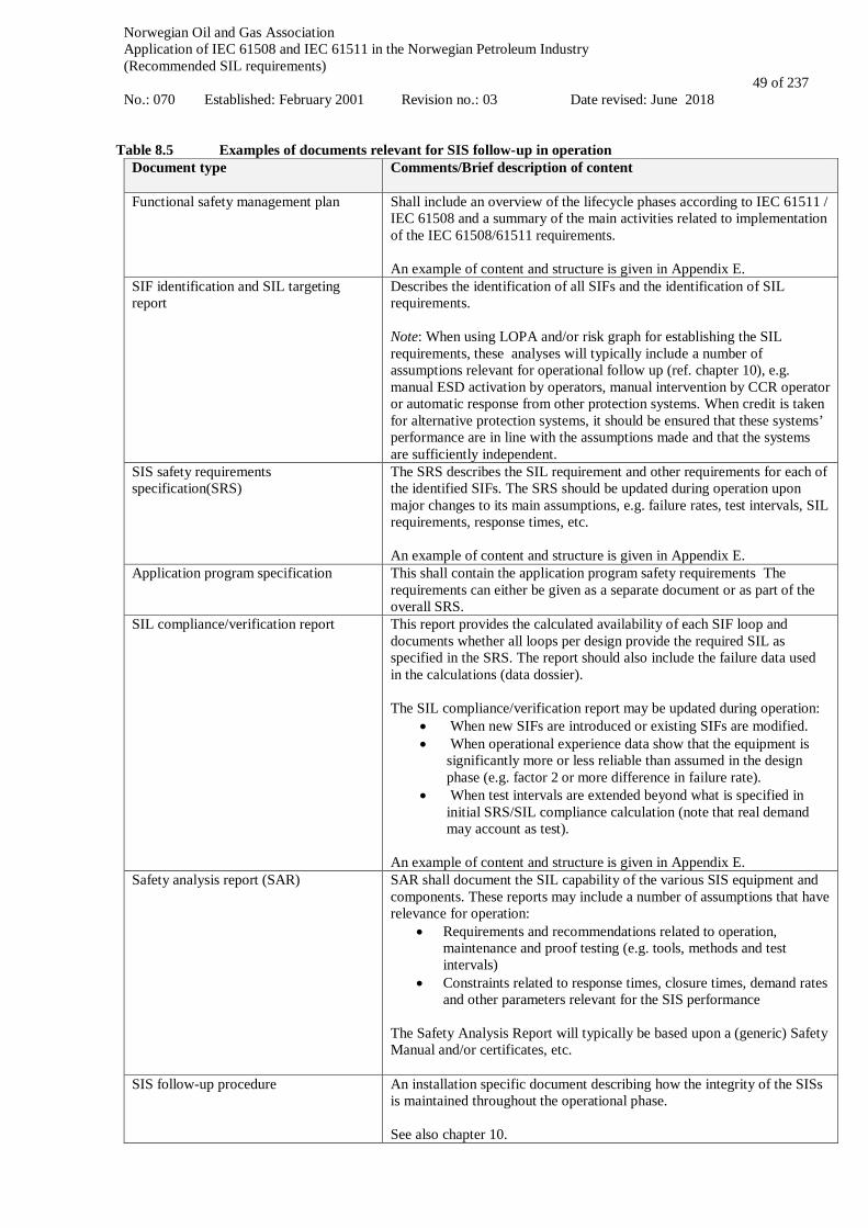
Norwegian Oil and Gas Association Application of IEC 61508 and IEC 61511 in the Norwegian Petroleum Industry (Recommended SIL requirements) No.: 070 Established: February 2001 Revision no.: 03 Date revised: June 2018
49 of 237
Table 8.5 Examples of documents relevant for SIS follow-up in operation
Document type
Comments/Brief description of content
Functional safety management plan Shall include an overview of the lifecycle phases according to IEC 61511 / IEC 61508 and a summary of the main activities related to implementation of the IEC 61508/61511 requirements. An example of content and structure is given in Appendix E.
SIF identification and SIL targeting report
Describes the identification of all SIFs and the identification of SIL requirements. Note: When using LOPA and/or risk graph for establishing the SIL requirements, these analyses will typically include a number of assumptions relevant for operational follow up (ref. chapter 10), e.g. manual ESD activation by operators, manual intervention by CCR operator or automatic response from other protection systems. When credit is taken for alternative protection systems, it should be ensured that these systems’ performance are in line with the assumptions made and that the systems are sufficiently independent.
SIS safety requirements specification(SRS)
The SRS describes the SIL requirement and other requirements for each of the identified SIFs. The SRS should be updated during operation upon major changes to its main assumptions, e.g. failure rates, test intervals, SIL requirements, response times, etc. An example of content and structure is given in Appendix E.
Application program specification
This shall contain the application program safety requirements The requirements can either be given as a separate document or as part of the overall SRS.
SIL compliance/verification report This report provides the calculated availability of each SIF loop and documents whether all loops per design provide the required SIL as specified in the SRS. The report should also include the failure data used in the calculations (data dossier). The SIL compliance/verification report may be updated during operation:
• When new SIFs are introduced or existing SIFs are modified. • When operational experience data show that the equipment is
significantly more or less reliable than assumed in the design phase (e.g. factor 2 or more difference in failure rate).
• When test intervals are extended beyond what is specified in initial SRS/SIL compliance calculation (note that real demand may account as test).
An example of content and structure is given in Appendix E.
Safety analysis report (SAR) SAR shall document the SIL capability of the various SIS equipment and components. These reports may include a number of assumptions that have relevance for operation:
• Requirements and recommendations related to operation, maintenance and proof testing (e.g. tools, methods and test intervals)
• Constraints related to response times, closure times, demand rates and other parameters relevant for the SIS performance
The Safety Analysis Report will typically be based upon a (generic) Safety Manual and/or certificates, etc.
SIS follow-up procedure
An installation specific document describing how the integrity of the SISs is maintained throughout the operational phase. See also chapter 10.

Norwegian Oil and Gas Association Application of IEC 61508 and IEC 61511 in the Norwegian Petroleum Industry (Recommended SIL requirements) No.: 070 Established: February 2001 Revision no.: 03 Date revised: June 2018
50 of 237
Document type
Comments/Brief description of content
Proof test procedures for instrumented safety systems
Procedures to ensure the quality and consistency of proof testing. See also chapter 10.
Override and bypass procedures/philosophies, including fault handling
A procedure describing the use of bypasses/overrides and handling of faults. See also chapter 10.
SIS management of change (MoC) procedure
Management of change procedures shall be in place to initiate, document, review, implement and approve changes to the SIS other than replacement in kind (IEC 61511-1, cl. 5.2.6.2.4) See also chapter 11.
The above listed documents shall be prepared during the design and pre-operation phase. Normally the SIS/SIF design documentation (six first documents listed) is the responsibility of the system integrator whereas the procedures for operation and maintenance (four last documents) is often prepared as part of the operator management system. It is a challenge that documents prepared during design are often difficult to interpret and implement in an operational context. Hence, for documents prepared during design and required during operation, efforts should be made to highlight relevant content and also consider having separate sections/parts dedicated for the operational phase.

Norwegian Oil and Gas Association Application of IEC 61508 and IEC 61511 in the Norwegian Petroleum Industry (Recommended SIL requirements) No.: 070 Established: February 2001 Revision no.: 03 Date revised: June 2018
51 of 237
9 SIS INSTALLATION, COMMISIONING AND VALIDATION
9.1 Objectives The objectives related to the requirements in this chapter are to:
• install the SIS according to specifications and drawings; • perform commissioning of the SIS so that it is ready for final system validation; and • validate, through inspection and testing, that the installed and mechanical complete SIS and its associated
SIFs, do achieve the requirements as stated in the SRS.
9.2 Requirements Relevant requirements are given in IEC 61511-1, cl. 14 and 15. Reference is also made to section 16 in the Activities Regulations. During commissioning it shall be checked and validated that:
• the requirements in the SRS is fulfilled; • all other relevant requirements, assumptions and pre-requisites are fulfilled; and • SIS proof-test procedures are available, applicable and able to detect all dangerous failures (also for
redundant functions).

Norwegian Oil and Gas Association Application of IEC 61508 and IEC 61511 in the Norwegian Petroleum Industry (Recommended SIL requirements) No.: 070 Established: February 2001 Revision no.: 03 Date revised: June 2018
52 of 237
10 SIS follow-up during operation
10.1 Objective The main objective of this chapter is to outline work processes, activities and methods considered appropriate to ensure that the integrity of the safety instrumented systems (SIS) is maintained throughout the operational lifetime of an installation. Note that this chapter does not discuss SIS modifications as this is covered separately in Chapter 11. The intention is to describe a practical approach towards implementing IEC 61511/IEC 61508 in the operational phase of an installation, and to provide specific guidance on areas such as:
• Relevant documentation • SIS follow-up activities • Relation to the barrier management activities • Roles and responsibilities related to the different follow-up activities • Relevant parameters to be followed up during operation • Data collection, including failure reporting and classification • Evaluation of performance deviations • Updating of failure rates and proof test intervals • Particular challenges related to SIS follow-up during well intervention
Competence requirements shall be specified for all SIS follow-up activities. This is further described in Chapter 5. An overall description of relevant SIS follow-up activities during operations should be given in the functional safety management plan (ref. Chapter 5). These activities should be further detailed in a specific SIS follow-up procedure, which shall ensure that the personnel responsible for SIL during the operational phase are involved in follow-up and modification projects concerning instrumented safety systems.
10.2 SIS documentation and premises for operation All requirements, assumptions and prerequisites from design that may affect how the SIS is operated and maintained should be transferred to operations in a consistent and complete manner. Documents prepared during the design phase that will provide input and requirements to SIS operation, testing and maintenance are discussed in Table 8.1 in section 8.8.
10.3 Summary of SIS follow-up activities The main activities associated with SIS follow-up during operations include:
• SIS operation • SIS testing and maintenance • SIS monitoring and verification (e.g. FSA), including data collection and analysis • Management of change / handling of performance deviations
This is illustrated in Figure 10.1 below.

Norwegian Oil and Gas Association Application of IEC 61508 and IEC 61511 in the Norwegian Petroleum Industry (Recommended SIL requirements) No.: 070 Established: February 2001 Revision no.: 03 Date revised: June 2018
53 of 237
SIS follow-up
SIS operation
SIS design and construction
Monitor and verify SIS performance
Management of change
(incl. handling of performance deviations)
SIS testing and maintenance
SIS decommisioning
Figure 10.1: SIS follow-up activities
SIS operation includes normal interaction with the SIS during operation; i.e. start-up and shutdown, casual observation of SIS degradation, recording of identified failures, initiation of maintenance requests or SIS modifications, implementation of compensating measures if the SIS is degraded or unavailable and setting, resetting and status tracking of bypasses, e.g. overrides, inhibits. SIS testing and maintenance includes scheduled inspections, repair and overhaul, replacements and proof testing. Each activity may be split into preparation, execution, restoration, and failure recording. Maintenance may be initiated upon equipment failures (corrective maintenance), scheduled on a regular basis according to calendar time or operating hours (preventive maintenance), or initiated upon request from a condition monitoring system (condition based maintenance). Monitoring and verification includes the collection of real time as well as historic SIS data (trends) and analysis of the collected data to verify if the established SIS performance requirements are met and operational assumptions are complied with. This also includes FSA and recertification activities as well as identification of possible performance deviations and the need for SIS modifications. Management of change addresses the follow-up of performance deviations and modification requests. For performance deviations, management of change means the analyses of the underlying causes and making recommendations for how to proceed. For modification requests, management of change means to perform an impact analysis, and determine if the modifications should be implemented, and if so, how the SIS is affected. SIS modifications are treated separately in chapter 11. Table 10.1 summarises recommended activities to ensure that the functional integrity of the SIS is maintained throughout the operating phase. Responsible position/role is also indicated, but will depend on the particular organisation of the installation under consideration. This should be specifically defined in the SIS follow-up procedure.

Norwegian Oil and Gas Association Application of IEC 61508 and IEC 61511 in the Norwegian Petroleum Industry (Recommended SIL requirements) No.: 070 Established: February 2001 Revision no.: 03 Date revised: June 2018
54 of 237
Table 10.1 Summary of recommended SIS follow-up activities and responsibilities
Type of activity
Description of SIS follow-up activities Responsible position/role (example)
Typical frequency
SIS operation
SIS operation during normal conditions and in degraded mode, including • Reporting of safety critical failures revealed during
activities other than testing • Logging and control of inhibits and overrides • Initiate actions and compensating measures upon non-
normal operating situations
Operation responsible/-supervisor
Continuous
Day to day SIS follow-up activities, including assistance to and interaction with operations and maintenance support groups on SIS related questions.
SIS responsible 1) Continuous
Handling of non-conformities, e.g. degraded SIS
SIS responsible Continuous
Identify and evaluate the need for SIS modifications based on reported failures, deficiencies and non-conformities, process changes, etc.
SIS responsible and SIL responsible 2)
Continuous
SIS testing and maintenance
SIS maintenance, testing and inspection according to maintenance programme and test procedures, including • Reporting of safety critical failures • Reporting of other failures • Repair and replacement of defect components
Maintenance responsible/-supervisor
Continuous
Go through maintenance/testing results and initiate necessary actions as required
Maintenance responsible/-supervisor
Continuous
SIS monitoring and verification
Ensure that SIS operation and maintenance is performed according to procedures and that relevant and competent personnel are involved in day-to-day SIS follow-up activities, both offshore and onshore.
Operation and maintenance (O&M) responsible/ supervisor
Continuous
Extract and perform quality assurance of reported SIS malfunction notifications in the maintenance system. Ensure sufficient quality of reported failures with respect to correct classification, including failure mode, failure cause and detection method.
Maintenance responsible/-supervisor
Monthly/bi-monthly
After a shutdown / SIS activation go through relevant reports and system logs to identify possible safety critical failures revealed and if relevant prepare corrective work orders.
SIS responsible As required
Perform regular reviews of operation and maintenance procedures in the light of discrepancies experienced during operation, SIS audits or as a result of non-conformance reports
SIS responsible As required
Perform SIS audits and verifications as required to ensure that SIS operation and maintenance is performed according to procedures and that the performance is in line with given criteria
HSE and SIL responsible
As required
As operational experience is gained and/or following major modifications, consider to perform functional safety assessment (FSA) and/or SIS recertification.
Third part As required
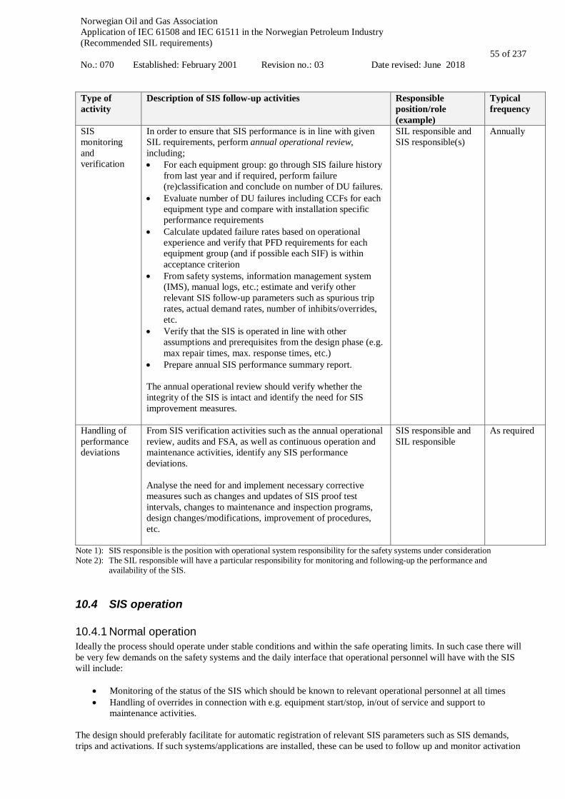
Norwegian Oil and Gas Association Application of IEC 61508 and IEC 61511 in the Norwegian Petroleum Industry (Recommended SIL requirements) No.: 070 Established: February 2001 Revision no.: 03 Date revised: June 2018
55 of 237
Type of activity
Description of SIS follow-up activities Responsible position/role (example)
Typical frequency
SIS monitoring and verification
In order to ensure that SIS performance is in line with given SIL requirements, perform annual operational review, including; • For each equipment group: go through SIS failure history
from last year and if required, perform failure (re)classification and conclude on number of DU failures.
• Evaluate number of DU failures including CCFs for each equipment type and compare with installation specific performance requirements
• Calculate updated failure rates based on operational experience and verify that PFD requirements for each equipment group (and if possible each SIF) is within acceptance criterion
• From safety systems, information management system (IMS), manual logs, etc.; estimate and verify other relevant SIS follow-up parameters such as spurious trip rates, actual demand rates, number of inhibits/overrides, etc.
• Verify that the SIS is operated in line with other assumptions and prerequisites from the design phase (e.g. max repair times, max. response times, etc.)
• Prepare annual SIS performance summary report. The annual operational review should verify whether the integrity of the SIS is intact and identify the need for SIS improvement measures.
SIL responsible and SIS responsible(s)
Annually
Handling of performance deviations
From SIS verification activities such as the annual operational review, audits and FSA, as well as continuous operation and maintenance activities, identify any SIS performance deviations. Analyse the need for and implement necessary corrective measures such as changes and updates of SIS proof test intervals, changes to maintenance and inspection programs, design changes/modifications, improvement of procedures, etc.
SIS responsible and SIL responsible
As required
Note 1): SIS responsible is the position with operational system responsibility for the safety systems under consideration Note 2): The SIL responsible will have a particular responsibility for monitoring and following-up the performance and
availability of the SIS.
10.4 SIS operation
10.4.1 Normal operation Ideally the process should operate under stable conditions and within the safe operating limits. In such case there will be very few demands on the safety systems and the daily interface that operational personnel will have with the SIS will include:
• Monitoring of the status of the SIS which should be known to relevant operational personnel at all times • Handling of overrides in connection with e.g. equipment start/stop, in/out of service and support to
maintenance activities. The design should preferably facilitate for automatic registration of relevant SIS parameters such as SIS demands, trips and activations. If such systems/applications are installed, these can be used to follow up and monitor activation
Norwegian Oil and Gas Association Application of IEC 61508 and IEC 61511 in the Norwegian Petroleum Industry (Recommended SIL requirements) No.: 070 Established: February 2001 Revision no.: 03 Date revised: June 2018
56 of 237
and demands on the SIS. Actual shutdowns during operation may be given credit as a full proof test given that the following conditions are fulfilled:
• the shutdown shall document equivalent information as registered during the corresponding described proof test;
• the shutdown shall cover all equipment included by the corresponding described proof test. If not, the equipment not covered shall be tested separately. In case of voting it shall be ensured that all redundant devices/channels are tested; and
• the shutdown occurs within the last half of the current test interval. In such case the component may be proof tested at its next stipulated interval (ref. Appendix F.3).
During design and operation one should ask whether the control room operator needs to know which SIF tags are most critical, and to what extent the control and safety system HMI should reflect information about SIL levels for the various SIFs. If the responsible operating company has procedures that require more extensive compensating measures for SIFs with high SIL requirements (e.g. HIPPS) it should be considered to highlight this on the system HMI.
10.4.2 Degraded operation Degraded modes of operation arise when a SIS (or a SIF) experiences some kind of reduced performance or reduced ability to perform its intended action. This may be due to an equipment failure or degradation, or an intentional override, inhibit or disabling of the SIS. In any case, degraded modes of operation may give an increased risk and therefore require compensating measures). The correct compensating measures shall be identified prior to different activities requiring overriding. Such activities may be (but are not limited to):
• Proof testing • Start-up and/or shutdown • Preventive maintenance activities • Field equipment malfunction and repair • Field equipment replacement
A system of controlling, approving, and recording the application of overrides to SIS shall be in place. The cumulative effects or consequences of overrides should be assessed and controlled. Operating a degraded system with compensating measures may be challenging, especially if the time of degradation extends beyond what is planned. To be able to control such situations the following should be defined:
• Maximum allowed mean repair time (MRT) defined for the SIS • What to do if MRTs are exceeded
Note: Definition of MRT and spare parts philosophy is part of designing a SIS to ensure SIS integrity and availability. The MRT should be stated in the SRS (ref. IEC 61511-1, cl. 10.3.2, point y) for each SIF, should be known to operations and maintenance personnel, and will help to define where the spare parts should be located (at plant or remote location warehouse). If the compensating measure during SIS overrides involves manual intervention, the available operator response time should be assessed, taking into consideration the foreseen time for revealing the abnormal situation as well as taking correct action.
10.5 SIS testing and maintenance The SIS shall be proof tested (see definition in section 4.1) and maintained regularly during operation in order to ensure that the functional integrity is maintained during the entire lifecycle. This includes repair of defective components and replacement with identical units having the same specification as well as registration of critical SIS failures (ref. section 10.6.1). Reference is also made to IEC 61511-1, cl. 16.
Norwegian Oil and Gas Association Application of IEC 61508 and IEC 61511 in the Norwegian Petroleum Industry (Recommended SIL requirements) No.: 070 Established: February 2001 Revision no.: 03 Date revised: June 2018
57 of 237
SIL classified safety functions and associated equipment shall be tested according to predefined proof test procedures scheduled in a PM programme as part of the maintenance system. The purpose of a proof test is to reveal all hidden dangerous failures. This shall be considered already during design of the SIS, in order to allow for e.g. partial testing of each component of the system. End-to-end testing may not always be suitable for such a purpose, for example it may not reveal the status of all components in redundant configurations. Proof testing of the SIS should reflect the real operating conditions as accurately as possible. As part of the proof testing, the results from the test shall be logged in a traceable manner into the maintenance system (see section 10.6.1 below). All components identified as part of any SIF should be traceable in the maintenance system in such way that failure data can be used to evaluate performance (ref. 10.6.1). Procedures for proof testing of sensors, logic and final elements shall be easily available. Test intervals for the SIL classified equipment shall be consistent with the test intervals given in the SRS. Some more details related to SIS testing are given in appendix F.4.
10.6 SIS monitoring and verification
10.6.1 Failure registration and analysis For the purpose of being able to follow-up and verify the SIL requirements it is very important that critical SIS failures revealed during operation and maintenance are properly registered and classified. All revealed failures or degradations of SIS components that require a corrective action/repair shall be registered with a malfunction notification in the maintenance system. Maintenance personnel performing failure registration should be properly trained in order to ensure high quality failure notifications. In particular it is important that:
• all failures are registered with correct, preferably pre-defined, failure codes, including criticality of failure. • the description of the failure in the free text field (failure type/mode, failure cause, history and detection
method) is as detailed as possible. Particular effort should be given to dangerous failures. • also software faults are included in the failure registration • the failures are registered "as found"-condition • the failure mode and failure cause are correctly specified • the detection method for the failure (upon proof testing, self-test, during normal operation, etc.) is correctly
specified The person responsible for the SIS system should periodically go through the reported malfunction notifications in order to ensure sufficient quality and correctness, and if required the notifications should be supplemented and/or re-classified in cooperation with the maintenance operators. Analysis and follow-up of the reported SIS failures are important activities in order to obtain a correct picture of the SIS performance and as a basis for initiating failure cause analyses and corrective measures as required. See Table 10.1 and Appendix F for more details concerning analysis of SIS failures.
10.6.2 Verification of SIL requirements during operation The registered SIS failures and other collected SIS parameters, including periodic reviews of actual demand rate data, should be used to verify that the experienced (or measured) safety integrity level of the SIS is acceptable as compared to the premises laid down in the design of the installation, represented by the SIL requirements. In Appendix F a practical approach on how to verify the SIL requirements during operation is further described. This also includes aspects such as collection of SIS parameters and updating of failure rates and test intervals based on operational experience.
10.6.3 Periodic review of SIF overrides Periodic review of overrides is useful in order to obtain an understanding of why overrides are used, their extent and if possible to reduce the number of overrides. Typical issues to look for are:
• long term overrides • most frequent overrides

Norwegian Oil and Gas Association Application of IEC 61508 and IEC 61511 in the Norwegian Petroleum Industry (Recommended SIL requirements) No.: 070 Established: February 2001 Revision no.: 03 Date revised: June 2018
58 of 237
• periodic use of overrides in relation to special operational modes • general override statistics
This may verify if the SIS is operated correctly and intentionally since too much override of a SIF may conflict with the required PFD as given by the SIL.
10.6.4 Demand rate review During normal operation the process should operate under stable conditions with very few demands on the safety systems. However, a process has a dynamic nature that may change over time. To understand process and equipment limitations and capabilities and to manage possible changes over time, the process should be monitored w.r.t. the safe operating boundaries. One way of examining the process/system is to review the SIF demand rates. The assumed SIF demand rates shall be given in the SRS and is a design parameter which defines how often we accept the function to be activated. If operated more frequent than stated in the SRS, the SIS is not performing within its assumed design limitations and additional risk reducing measures should be considered.
10.7 Special issues related to workover Special considerations need to be taken for SIS follow up for workover systems (WOS) and workover control systems (WOCS) due to the nature of such systems:
• Various combinations of components of SIS can be mobilized; used, de-mobilized and stored independently (e.g. WOCS can be mobilized in completely different location than the surface flow tree (SFT)).
• Many mobilizations / demobilizations during the life cycle and consequently inadequate definition of commissioning and decommissioning for this type of equipment.
• The equipment may be stored onshore for longer periods. • The crew usually "follows" the equipment for a limited period of time
As a result, proof test intervals should also take frequency of operations into consideration and not solely fixed time intervals. If a module in a stack is changed, an integration test (commissioning) has to be performed before standard function- and pressure- test regime is applied (proof test). Effort should be made to design the tests to reveal as many of the dangerous failures as possible, since frequent testing (with high test coverage) is often credited in the PFD calculations. See also section 10.5. The following considerations are of importance when operating WOS:
• Care should be taken in increasing the test interval for WOS based on updated PFD calculations (operational feedback) since the nature of such systems and associated collection of reliability data is so complex (ref. discussion above). One should:
o Perform proof test prior to each operation. Test is accepted if: No failure is detected in the activating system No failure is detected when operating the valve (without cutting, but including test of
sealing capability) o Monitor data for components part of barrier functions to:
Ensure sufficient barrier performance Optimise for safe and efficient operations, by optimising the maintenance within the
limitations of the overall test interval o Perform necessary maintenance with regards to:
Maximum number of operations of specific barrier functionalities (worn seals, EQD disconnection, valve closure).
Manual activities such as pre-charging, lubrication of connectors, seal replacement. • If parts of the WOS are used for different operations or in combination with other systems, a proof test of the
complete system should be performed before operation. Ensure that the proof test is recorded and that there is sufficient traceability of the components in use;
• Proof test coverage for e.g. cutting valves should be considered. The valves are normally qualified for one cut only, and can as such not be fully proof tested at each test interval;
• If the system is proof tested and then stored offshore, an extended test and verification/commissioning needs to be performed prior to operation.
• SIL verification of WOS should be performed when sufficient operational information is available and as part of the regular WOS recertification.

Norwegian Oil and Gas Association Application of IEC 61508 and IEC 61511 in the Norwegian Petroleum Industry (Recommended SIL requirements) No.: 070 Established: February 2001 Revision no.: 03 Date revised: June 2018
59 of 237
All devices identified as part of any SIF should be included in scope for recertification. The figure below illustrates a possible allocation of responsibilities with respect to SIS follow-up during workover.
Figure 10.2: Follow-up responsibilities during workover
Further evaluation will be the responsibility of the workover system owner in consultation with personnel with competence in the assessment of SIL. The required frequency of preparing a SIL status report should be considered. Due to the nature of the equipment, the frequency of use and the amount of data available, it may be sufficient to perform a WOCS performance review (similar to an annual SIS operational review, ref. Table 10.1) every 5th year, possibly in connection with equipment recertification.
WOCS operator
Collect data offshore
WOCS supervisor
Send data to project management
Field operations project management
Forward data to WOCS / SIL engineering
WOCS / SIL engineering
Perform operational review, evaluate the
SIL status and document results in a
report
SIL status of SIFs ok?
Further evaluation required
NOYES
Norwegian Oil and Gas Association Application of IEC 61508 and IEC 61511 in the Norwegian Petroleum Industry (Recommended SIL requirements) No.: 070 Established: February 2001 Revision no.: 03 Date revised: June 2018
60 of 237
11 SIS Modification Modifications are defined as any changes to the SIS other than those defined in chapter 10; SIS operation and maintenance.
11.1 Objective of Management Of Change (MOC) The objectives of the requirements of this sub-clause are:
• to ensure that modifications to any SIS are properly reviewed, approved and planned prior to making the change;
• to ensure that the required safety integrity of the SIS is maintained in the event of any changes made to the SIS.
11.2 MOC procedure A written procedure shall be in place to initiate, review, approve and execute changes to the SIS other than “replacement in kind”. The MOC procedure may be required as a result of modifications in the following areas:
• component(s) with different characteristics; • new proof test interval or procedures; • changed set-point due to changes in operating conditions; • changes in operating procedures; • a new or amended safety legislation; • modified process conditions; • changes to the SRS; • a correction of software or firmware errors; • correction of systematic failures; • a failure rate higher than desired; • increased demand rate on the SIS; or • software (embedded utility, application).
The MOC procedure shall include an impact analysis to ensure that the following considerations are addressed prior to any change:
• the technical basis for the proposed change; • the general impact of change on safety and health; • the impact of change on other parts of the process and associated equipment; • modifications of operating procedures; • necessary time period for the change; • authorisation requirements for the proposed change; • availability of memory space; • effect on response time; and • online versus offline change, and the risks involved.
The review of the change shall ensure that:
• the required safety integrity has been maintained; and • personnel from appropriate disciplines have been included in the review process.
Personnel affected by the change shall be informed and trained prior to implementation of the change or start-up of the process, as appropriate. In principle, all changes to the SIS shall initiate a return to the appropriate phase (first phase affected by the modification) of the safety lifecycle. All subsequent safety lifecycle phases shall then be carried out, including

Norwegian Oil and Gas Association Application of IEC 61508 and IEC 61511 in the Norwegian Petroleum Industry (Recommended SIL requirements) No.: 070 Established: February 2001 Revision no.: 03 Date revised: June 2018
61 of 237
appropriate verification that the change has been carried out correctly and documented. Implementation of all changes (including application software) should adhere to the previously established SIS design procedures. Deviations from the above are allowed for limited software changes in existing SIS, provided the impact analysis identifies appropriate review activities and partial testing required to ensure that the SIL has not been compromised. This shall also apply to system software upgrades through the safety lifecycle. The impact analysis for software modifications shall, as a minimum, document analysis of the items described in the following table and define the appropriate method of achieving the recommended level of verification/validation (R = review, PT = partial testing):
Impact analysis shall document the effect on: U
pgra
ded
syst
em
Softw
are
New
pro
cess
Mod
ified
pro
cess
(F
ield
equ
ipm
ent)
Mod
ified
func
tion
(App
. pro
gram
mes
C
&E,
pre
-test
ed
mac
ros e
tc.)
Cha
ract
eriz
atio
ns
(App
licat
ion
Thre
shol
ds, s
pans
, tim
ers,
filte
rs e
tc.)
Existing equipment under control (process) R PT PT PT Existing related equipment under control (process) R PT R R R Existing related equipment under control (functional) e.g. software interfaces logic to logic, controller to controller etc.
PT PT PT PT R
Existing SIS (physical) e.g. hardware capacity, power requirements etc. R R R
Existing SIS (functional) e.g. memory usage, transmission capacities etc. R R R
Existing SIS (characteristics) e.g. cycle times, response times etc. R R R R
HMI PT PT PT PT R For existing SIS designed and constructed in accordance with codes, standards or practices prior to the issue of IEC 61508, the owner/operator shall determine that changes to the SIS as a minimum comply with the original design basis. However, it should be considered to upgrade the existing SRS or generate one in accordance with IEC 61508, when for example the following changes are introduced:
• major replacements or upgrades of the SIS; • major units or modules are replaced or installed; • major changes in the characteristics of the process medium handled by the installation; • new rules with retroactive effect result in the existing SIS failing to meet the requirements; or • new knowledge gained from, for example, incidents or major studies indicate that the existing SIS can no
longer deliver an appropriate performance or an acceptable level of integrity.
11.3 MOC documentation All changes to operating procedures, process safety information, and SIS documentation (including software) shall be noted prior to start-up, and updated accordingly. The documentation shall be appropriately protected against unauthorised modification, destruction, or loss. All SIS documents shall be revised, amended, reviewed, approved, and be under the control of an appropriate document control procedure.

Norwegian Oil and Gas Association Application of IEC 61508 and IEC 61511 in the Norwegian Petroleum Industry (Recommended SIL requirements) No.: 070 Established: February 2001 Revision no.: 03 Date revised: June 2018
62 of 237
12 SIS Decommissioning
12.1 Objectives The objectives of the requirements of this chapter are:
• to ensure that before removing any SIS from active service, a proper review is conducted and required authorisation is obtained; and
• to ensure that the required safety instrumented functions remain operational during decommissioning activities.
12.2 Requirements Management of change procedures as described in section 11.2 shall be implemented for all decommissioning activities. The impact of SIS decommissioning on adjacent operating units and facilities or other field services shall be evaluated prior to decommissioning.
Norwegian Oil and Gas Association Application of IEC 61508 and IEC 61511 in the Norwegian Petroleum Industry (Recommended SIL requirements) No.: 070 Established: February 2001 Revision no.: 03 Date revised: June 2018
63 of 237
APPLICATION OF IEC 61508 AND IEC 61511
IN THE NORWEGIAN PETROLEUM INDUSTRY
(Recommended SIL requirements)
Appendix A
BACKGROUND FOR MINIMUM SIL REQUIREMENTS

Norwegian Oil and Gas Association Application of IEC 61508 and IEC 61511 in the Norwegian Petroleum Industry (Recommended SIL requirements) No.: 070 Established February 2001 Revision no.: 03 Date revised: June 2018
64 of 237
CONTENT
A.1 INTRODUCTION ....................................................................................................................................... 66 A.1.1 RATIONALE FOR THE MINIMUM SIL APPROACH ....................................................................................... 66 A.1.2 CONSIDERATIONS AND ASSUMPTIONS ..................................................................................................... 66
A.2 DATA DOSSIER ......................................................................................................................................... 68
A.2.1 RELIABILITY DATA ................................................................................................................................ 68
A.3 PSD FUNCTIONS ....................................................................................................................................... 75
A.3.1 PROCESS SEGREGATION IN PSD .............................................................................................................. 75 A.3.2 PSD FUNCTIONS: PAHH, LAHH, LALL (PRIMARY PROTECTIONS).......................................................... 77 A.3.3 PSD/ESD FUNCTION: LAHH IN FLARE KO DRUM ................................................................................... 79 A.3.4 PSD FUNCTION: TAHH/TALL ............................................................................................................... 81 A.3.5 PSD FUNCTION: PALL (PRIMARY PROTECTION AGAINST LEAKAGE) ........................................................ 82
A.4 ESD SEGREGATION WITH ONE VALVE ............................................................................................. 83
A.5 BLOWDOWN WITH ONE VALVE.......................................................................................................... 85
A.6 ISOLATION OF ONE TOPSIDE WELL .................................................................................................. 87
A.6.1 ISOLATION OF PRODUCTION BORE UPON HIGH PRESSURE (PSD) ............................................................... 88 A.6.2 ISOLATION OF PRODUCTION/INJECTION BORE IN ONE TOPSIDE WELL (ESD) .............................................. 88 A.6.3 ISOLATION OF ANNULUS IN ONE TOPSIDE GAS LIFT WELL ......................................................................... 90 A.6.4 ISOLATION OF ONE CHEMICAL INJECTION LINE IN TOPSIDE WELL .............................................................. 90
A.7 ESD ISOLATION OF RISER .................................................................................................................... 92
A.8 FIRE AND GAS DETECTION .................................................................................................................. 93
A.8.1 FIRE DETECTION WITH ONE DETECTOR .................................................................................................... 93 A.8.2 GAS DETECTION WITH ONE DETECTOR .................................................................................................... 94 A.8.3 GAS DETECTION WITH ASPIRATOR........................................................................................................... 94 A.8.4 START OF FIRE PUMPS UPON CHANGE OF PRESSURE OR FLOW ................................................................... 95
A.9 HVAC .......................................................................................................................................................... 97 A.9.1 CLOSING OF ONE FIRE DAMPER ............................................................................................................... 97 A.9.2 CLOSING OF TWO FIRE DAMPERS AND STOP OF FAN.................................................................................. 97 A.9.3 CLOSING OF MAIN AIR INTAKE ................................................................................................................ 98
A.10 ELECTRICAL ISOLATION ................................................................................................................. 99
A.11 FIREWATER SUPPLY ........................................................................................................................ 101
A.11.1 RELEASE OF DELUGE ................................................................................................................................ 101 A.11.2 RELEASE OF INERGEN ............................................................................................................................... 102 A.11.3 RELEASE OF WATER MIST ......................................................................................................................... 103 A.11.4 WATER FILLING OF JACKET ....................................................................................................................... 104
A.12 BALLASTING ...................................................................................................................................... 105 A.12.1 START OF BALLAST SYSTEM...................................................................................................................... 105 A.12.2 EMERGENCY STOP OF BALLAST SYSTEM .................................................................................................... 107
A.13 ISOLATION OF ONE SUBSEA WELL .............................................................................................. 109
A.13.1 PRIMARY AND SECONDARY BARRIER ISOLATION OF PRODUCTION/INJECTION BORE IN ONE SUBSEA WELL ... 112 A.13.2 SECONDARY BARRIER ISOLATION OF ANNULUS IN ONE SUBSEA GAS LIFT WELL .......................................... 114 A.13.3 SECONDARY BARRIER ISOLATION OF ONE CHEMICAL INJECTION LINE IN ONE SUBSEA WELL ....................... 115 A.13.4 SECONDARY BARRIER ISOLATION OF ONE SERVICE LINE FROM ONE SUBSEA WELL ...................................... 116 A.13.5 SUMMARY – ISOLATION OF ONE SUBSEA WELL .......................................................................................... 117

Norwegian Oil and Gas Association Application of IEC 61508 and IEC 61511 in the Norwegian Petroleum Industry (Recommended SIL requirements) No.: 070 Established February 2001 Revision no.: 03 Date revised: June 2018
65 of 237
A.14 DRILLING ............................................................................................................................................ 119
A.14.1 SHEAR SEAL RAM FUNCTION ..................................................................................................................... 121 A.14.2 SEQUENCED SHUTDOWN FUNCTIONS (EMERGENCY DISCONNECT, AUTOSHEAR) ........................................ 122 A.14.3 MECHANICAL RAM LOCK FUNCTION ......................................................................................................... 124 A.14.4 DOCUMENTATION OF PERFORMANCE FOR BOP FUNCTIONS ....................................................................... 124
A.15 WELL WORKOVER ........................................................................................................................... 125 A.15.1 SUBSEA WORKOVER PSD ........................................................................................................................ 132 A.15.2 OPEN WATER WORKOVER ESD ............................................................................................................... 133 A.15.3 OPEN WATER WORKOVER EQD WITH ISOLATION ..................................................................................... 135 A.15.4 LANDING STRING ESD ............................................................................................................................ 136 A.15.5 LANDING STRING EQD ........................................................................................................................... 137 A.15.6 SURFACE WORKOVER OPERATIONS .......................................................................................................... 137 A.15.7 SHEAR SEAL RAM FUNCTION ................................................................................................................... 138 A.15.8 HYDRAULIC MASTER VALVE FUNCTION ................................................................................................... 140
A.16 MANUAL INITIATORS: ESD AND F&G .......................................................................................... 142
A.17 REFERENCES ...................................................................................................................................... 143

Norwegian Oil and Gas Association Application of IEC 61508 and IEC 61511 in the Norwegian Petroleum Industry (Recommended SIL requirements) No.: 070 Established February 2001 Revision no.: 03 Date revised: June 2018
66 of 237
A.1 Introduction This appendix documents the background for the minimum SIL requirements as presented in Table 7.5.1, 7.5.2, 7.5.3, 7.5.4 and 7.5.5, in section 7.5, of this guideline. Reference is made to section 1.1 for the rationale behind the minimum SIL. The formulas used in the calculations are based on the PDS method handbook and described in Appendix D.
A.1.1 Rationale for the minimum SIL approach The minimum requirements promoted by this guideline are based upon the following approach:
1. Identification of typical SIFs applied within the industry, including process shutdown functions, emergency shutdown functions, fire and gas functions, and specific well and workover functions.
2. Calculation of achievable probability of failure on demand (PFD) for these functions using typical loop diagrams and generic reliability data based on industry experience. The calculations are documented in this appendix.
3. Definition of obtainable PFD based on the calculations (and if necessary by judgment of application and practicability)
4. Allocation of corresponding SIL for the typical SIF, based on obtainable PFD and with reference to PFD range given in Table 8.1. For some functions where only SIL 1 is achievable, the minimum SIL has been elaborated by a specific PFD requirement
The resulting performance requirements are referred to as minimum SIL in this guideline. Requirements to SIFs should be described in the safety requirement specification (SRS). It should be noted that for some "global" functions, for example ESD segregation and F&G detection, it has been difficult to define generic functions since the number of ESD valves to close or the number of detectors to function, will vary from case to case. For these cases, simple sub-functions including one valve (or one detector) have been defined and a SIL requirement for these sub-functions given. For the purpose of QRA and verification of the overall risk level, it is however important that the PFD of the complete functions are calculated.
A.1.2 Considerations and assumptions When stating minimum SIL requirements, a main objective is to ensure a performance level considered achievable by today’s standard and industry practices. Thus, there are certain considerations to be made in order to avoid that the stated criteria actually result in a relaxation of the safety level. Some of these considerations are discussed below. When using “conservative” failure rates (λDU) and/or long proof test intervals (τ) for calculating the failure probability of a given function, the resulting PFD becomes “high”. Accordingly, a “low” SIL value can be claimed for the function, resulting in a non-conservative requirement in the minimum SIL table. Consequently, it is important that the input data for the calculations in this appendix are realistic both with respect to the failure rates being representative for new equipment as well as the proof test intervals. However, several years of experience with the NOG-070 guideline has shown that the minimum SIL is often used in combination with other SIL determination techniques. This implies that "special functions" (i.e. functions identified as being particularly critical, non-critical or functions not included in section 7.5 are analysed separately. The failure data, which are presented in section A.2 and used in the quantifications, are typical values based on operational field feedback (based mainly on the PDS data handbook). However, these values should not be used without considering their applicability. Therefore, if additional knowledge and/or application specific data are available, these data should be applied in the SIL calculations. See also section 8.5 regarding failure data and qualification of failure data used for PFD calculations. The PFD calculations in this appendix are based on a number of general assumptions concerning:
• Failure rate λDU and proof test interval according to the data dossier in section A.2 • Diagnostic coverage (DC), i.e. the rate of critical failures undetectable by automatic self-test. The λDU values
used in the example calculations assume a certain diagnostic coverage, which is given from the applied data source (mainly PDS data handbook). It is therefore important that during the process of SIL verification, the assumed diagnostic coverage factors be properly documented.
• It is assumed that all DU failures are detected during proof test unless otherwise stated (equivalent to 100 % Proof test coverage (PTC)).

Norwegian Oil and Gas Association Application of IEC 61508 and IEC 61511 in the Norwegian Petroleum Industry (Recommended SIL requirements) No.: 070 Established February 2001 Revision no.: 03 Date revised: June 2018
67 of 237
• Loop monitoring is assumed. For the simplified loop diagrams shown in this appendix, some details are omitted, e.g. electrical barriers, junction boxes, cables and signal adapters. In the final calculations, to prove compliance, all components and modules that may influence the failure probability of the SIF have to be included.
• All SIFs have been treated as low demand functions. Separate considerations should be made for each specific case in order to verify that this assumption is relevant.
• For all logic units including I/O in the examples, the values for “Programmable safety system” have been applied (ref. Tables A.1-1 and A.2-1) unless otherwise stated.
• Appendix D documents the applied formulas, which are based on the PDS method, /A.3/ Hence, when applying the minimum SIL, it should be ensured that the applied components/equipment satisfy the assumptions listed above in addition to the specific assumptions made for each safety function presented in this appendix, e.g. if the design is de-energized to safe state (Normally Energized (NE)) or energized to safe state (Normally De-energized (NDE)). Note that when deriving the SIL requirements in this Appendix, the minimum HFT (hardware fault tolerance) requirements as referred in Table 8.4 in the main part (ref. IEC 61511-1, Table 6) has not been explicitly commented for each function. However, given the "new" HFT requirements as specified in edition 2 of IEC 61511, all "typical loops" specified in this Appendix fulfil the structural HFT requirements.
Norwegian Oil and Gas Association Application of IEC 61508 and IEC 61511 in the Norwegian Petroleum Industry (Recommended SIL requirements) No.: 070 Established February 2001 Revision no.: 03 Date revised: June 2018
68 of 237
A.2 Data dossier This section contains a collection of the reliability data used in the calculations, as well as the assumed proof test intervals.
A.2.1 Reliability Data Table A.2.1 summarizes the failure rates used for topside equipment in this appendix. λDU is here the rate of failures causing the component to fail upon demand, undetected by automatic self-test. The reliability data are to a large degree based upon and documented in the PDS 2013 data handbook and OREDA handbooks. The PDS failure rates are mainly based on operational experience (combination of data from various data sources such as the OREDA database and handbooks, operational reviews, RNNP, etc.) and as such reflect some kind of average field performance of the components. See discussion in section 8.5.
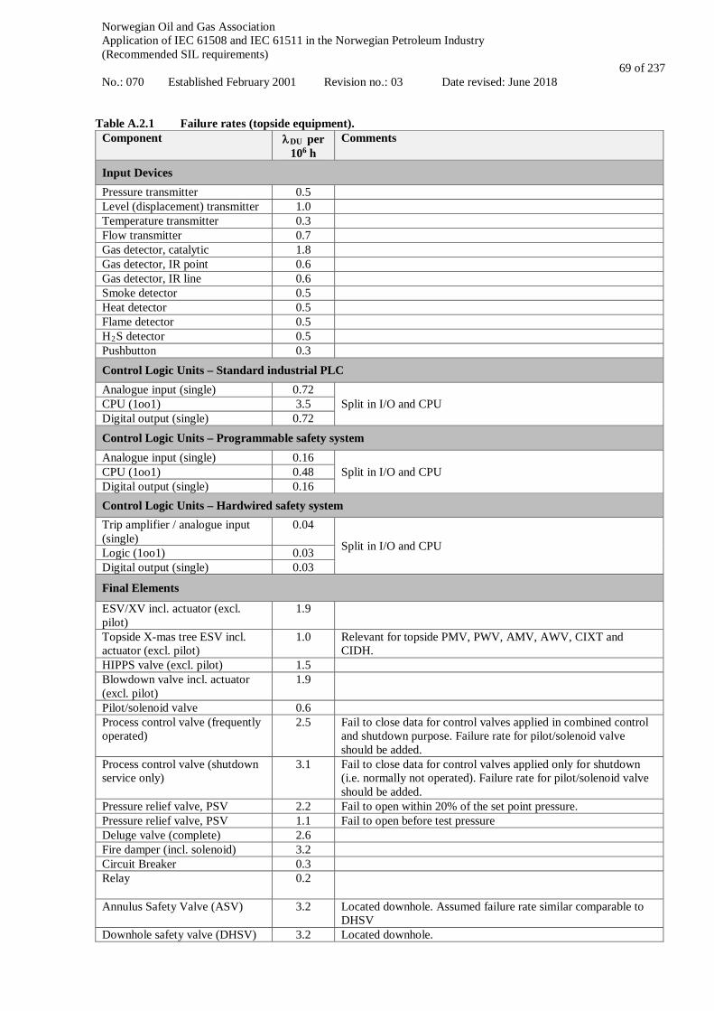
Norwegian Oil and Gas Association Application of IEC 61508 and IEC 61511 in the Norwegian Petroleum Industry (Recommended SIL requirements) No.: 070 Established February 2001 Revision no.: 03 Date revised: June 2018
69 of 237
Table A.2.1 Failure rates (topside equipment).
Component λDU per 106 h
Comments
Input Devices Pressure transmitter 0.5 Level (displacement) transmitter 1.0 Temperature transmitter 0.3 Flow transmitter 0.7 Gas detector, catalytic 1.8 Gas detector, IR point 0.6 Gas detector, IR line 0.6 Smoke detector 0.5 Heat detector 0.5 Flame detector 0.5 H2S detector 0.5 Pushbutton 0.3 Control Logic Units – Standard industrial PLC Analogue input (single) 0.72
Split in I/O and CPU CPU (1oo1) 3.5 Digital output (single) 0.72 Control Logic Units – Programmable safety system Analogue input (single) 0.16
Split in I/O and CPU CPU (1oo1) 0.48 Digital output (single) 0.16 Control Logic Units – Hardwired safety system Trip amplifier / analogue input (single)
0.04
Split in I/O and CPU Logic (1oo1) 0.03 Digital output (single) 0.03
Final Elements
ESV/XV incl. actuator (excl. pilot)
1.9
Topside X-mas tree ESV incl. actuator (excl. pilot)
1.0 Relevant for topside PMV, PWV, AMV, AWV, CIXT and CIDH.
HIPPS valve (excl. pilot) 1.5 Blowdown valve incl. actuator (excl. pilot)
1.9
Pilot/solenoid valve 0.6 Process control valve (frequently operated)
2.5 Fail to close data for control valves applied in combined control and shutdown purpose. Failure rate for pilot/solenoid valve should be added.
Process control valve (shutdown service only)
3.1 Fail to close data for control valves applied only for shutdown (i.e. normally not operated). Failure rate for pilot/solenoid valve should be added.
Pressure relief valve, PSV 2.2 Fail to open within 20% of the set point pressure. Pressure relief valve, PSV 1.1 Fail to open before test pressure Deluge valve (complete) 2.6 Fire damper (incl. solenoid) 3.2 Circuit Breaker 0.3 Relay
0.2
Annulus Safety Valve (ASV)
3.2 Located downhole. Assumed failure rate similar comparable to DHSV
Downhole safety valve (DHSV) 3.2 Located downhole.

Norwegian Oil and Gas Association Application of IEC 61508 and IEC 61511 in the Norwegian Petroleum Industry (Recommended SIL requirements) No.: 070 Established February 2001 Revision no.: 03 Date revised: June 2018
70 of 237
Component λDU per 106 h
Comments
Firewater pump (centrifugal) (Including power transmission, pump unit, control &monitoring, lubrication system and misc.)
Fail to start on
demand :
PFD = 3.5 ⋅ 10-3
OREDA 2002, 1.3.1.18 OREDA 2009, 1.3.1.13 OREDA 2015, 1.3.1.1.2 The failure probability includes only the critical failure mode “fail to start” (“fail while running” not included). Based on 2597 demands (estimated) and 9 FTS failures. Number of demands in OREDA 2009 is unknown and is assumed proportional to operational time (based on data from OREDA 2002 and 2015).
Firewater diesel engine Fail to start on demand:
PFD =
4.6 ⋅ 10-3
OREDA 2002, 1.4.1.5 OREDA 2009, 1.4.1.4 OREDA 2015, 1.4.1.3 The failure rate includes only the critical failure mode “fail to start on demand” (“breakdown” not included). Based on 3293 demands (estimated) and 15 FTS failures. Number of demands in OREDA 2009 is unknown and is assumed proportional to population size (based on data from OREDA 2002 and 2015).
Electric generator (motor driven, 1000–3000 kVA)
Fail to start on demand:
PFD =
1.4 ⋅ 10-3
OREDA 2002, 2.1.1.1.2 OREDA 2009, 2.1.1.3 OREDA 2015, 2.1.1.1.2 The failure rate includes only the critical failure mode “fail to start on demand” (“spurious stop” not included). Based on 2088 demands (estimated) and 3 FTS failures. Number of demands in OREDA 2009 is unknown and is assumed proportional to operational time (based on data from OREDA 2002 and 2015).
Electric motor (pump driver, water firefighting)
Fail to start on demand:
PFD =
3.6 ⋅ 10-3
OREDA 2002, 2.2.2 OREDA 2009, 2.2.2.14 OREDA 2015, 2.2.2.14 The failure rate includes only the critical failure mode “fail to start on demand”. Based on 5487 demands (estimated) and 20 FTS failures. Number of demands in OREDA 2009 is unknown and is assumed proportional to operational time (based on data from OREDA 2002 and 2015).
Table A.2.2 summarizes the failure rates used for subsea equipment in this appendix. These data are based on PDS data handbook 2013 and data from the OREDA subsea database.

Norwegian Oil and Gas Association Application of IEC 61508 and IEC 61511 in the Norwegian Petroleum Industry (Recommended SIL requirements) No.: 070 Established February 2001 Revision no.: 03 Date revised: June 2018
71 of 237
Table A.2.2 Failure rates (subsea production / downhole equipment). Component λDU per
106 h Comments
Final Elements
Manifold isolation valve 0.40 Assuming a 70 % / 30 % distribution between safe and dangerous failures, and 0 % coverage.
Solenoid control valves / Directional control valves (DCV) (in subsea control module, SCM)
0.16 Assuming a 60 % / 40 % distribution between safe and dangerous failures, and 0 % coverage.
Production master valve (PMV) and wing valve (PWV)
0.18 Assuming a 30 % / 70 % distribution between safe and dangerous failures, and 0 % coverage.
Cross-Over Valve (XOV) 0.18 Assumed similar failure rate as for PMV/PWV Annulus master valve (AMV) and Annulus wing valve (AWV)
0.18 Assumed similar failure rate as for PMV/PWV
Chemical injection valve (CIXT/CIDH)
0.22 Assuming a 40 % / 60 % distribution between safe and dangerous failures, and 0 % coverage.
MEG injection valve (MIV 0.22 Assumed similar failure rate as for chemical injection valve Downhole safety valve (DHSV)
3.2 Assuming a 40 % / 60 % distribution between safe and dangerous failures, and 0 % coverage.
Tables A.2.3 (topside) and A.2.4 (subsea production) summarize the input data with respect to resulting PFD (probability of failure on demand), i.e.:
PFD ≈ λDU ⋅ τ /2. The tables include the assumed proof test intervals for the equipment. The values are based on knowledge from various industry projects. Table A.2.3 Summary of component reliability values used in example calculations – topside.
Component Proof test interval
τ (months)
Fail. rate λDU per 106 hours PFD
Input Devices
Pressure transmitter 12 0.5 2.2 ⋅ 10-3 Level (displacement) transmitter 12 1.0 4.4 ⋅ 10-3 Temperature transmitter 12 0.3 1.3 ⋅ 10-3 Flow transmitter 12 0.7 3.1 ⋅ 10-3 Gas detector, catalytic 12 1.8 7.9 ⋅ 10-3 Gas detector, IR point 12 0.6 2.6 ⋅ 10-3 Gas detector, IR line 12 0.6 2.6 ⋅ 10-3 Smoke detector 12 0.5 2.2 ⋅ 10-3 Heat detector 12 0.5 2.2 ⋅ 10-3 Flame detector 12 0.5 2.2 ⋅ 10-3 H2S detector 12 0.5 2.2 ⋅ 10-3 Pushbutton 12 0.3 1.3 ⋅ 10-3 Control Logic Units – Standard industrial PLC Analogue input (single) 12 0.72 3.1 ⋅ 10-3 CPU (1oo1) 12 3.5 1.5 ⋅ 10-2 Digital output (single) 12 0.72 3.1 ⋅ 10-3 Total CLU (single I/O and CPU) 12 5.0 2.1 ⋅ 10-2 Control Logic Units – Programmable safety system
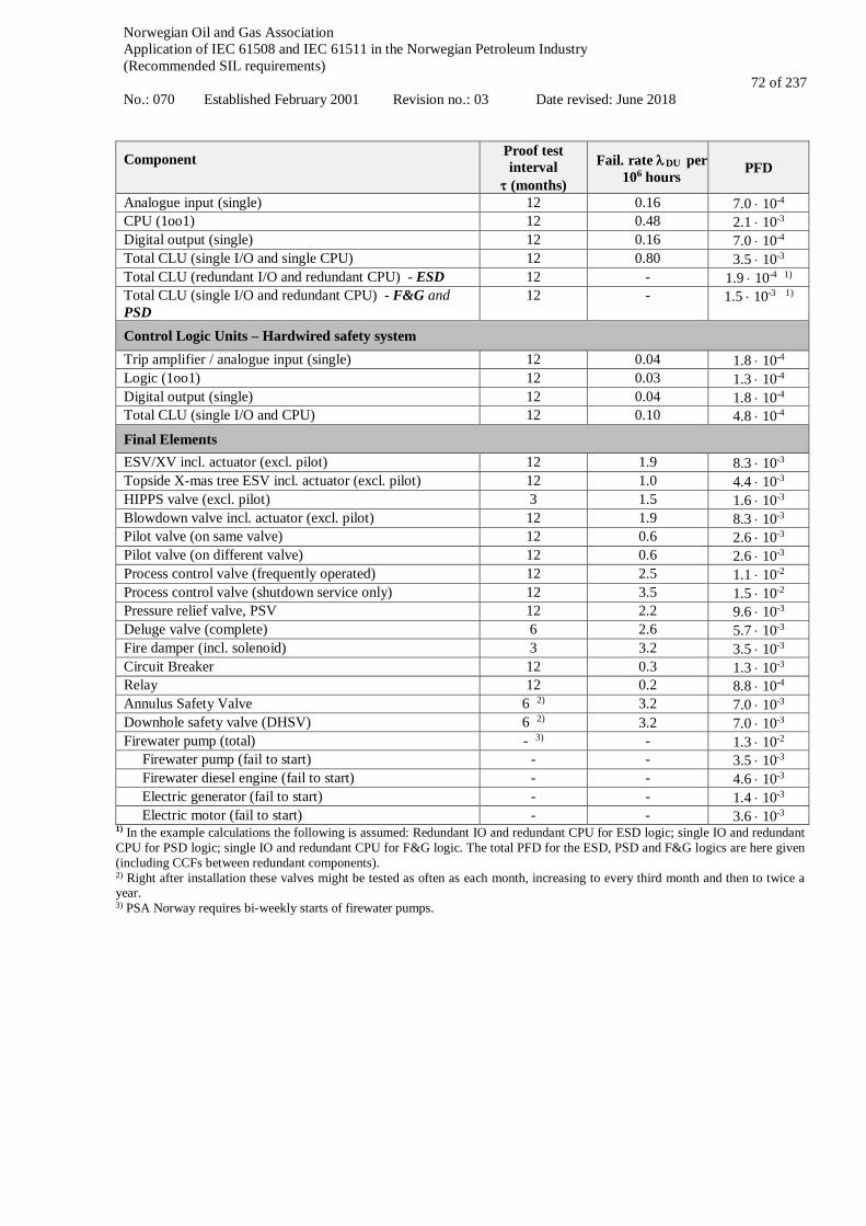
Norwegian Oil and Gas Association Application of IEC 61508 and IEC 61511 in the Norwegian Petroleum Industry (Recommended SIL requirements) No.: 070 Established February 2001 Revision no.: 03 Date revised: June 2018
72 of 237
Component Proof test interval
τ (months)
Fail. rate λDU per 106 hours PFD
Analogue input (single) 12 0.16 7.0 ⋅ 10-4 CPU (1oo1) 12 0.48 2.1 ⋅ 10-3 Digital output (single) 12 0.16 7.0 ⋅ 10-4 Total CLU (single I/O and single CPU) 12 0.80 3.5 ⋅ 10-3 Total CLU (redundant I/O and redundant CPU) - ESD 12 - 1.9 ⋅ 10-4 1) Total CLU (single I/O and redundant CPU) - F&G and PSD
12 - 1.5 ⋅ 10-3 1)
Control Logic Units – Hardwired safety system Trip amplifier / analogue input (single) 12 0.04 1.8 ⋅ 10-4 Logic (1oo1) 12 0.03 1.3 ⋅ 10-4
Digital output (single) 12 0.04 1.8 ⋅ 10-4
Total CLU (single I/O and CPU) 12 0.10 4.8 ⋅ 10-4 Final Elements ESV/XV incl. actuator (excl. pilot) 12 1.9 8.3 ⋅ 10-3 Topside X-mas tree ESV incl. actuator (excl. pilot) 12 1.0 4.4 ⋅ 10-3 HIPPS valve (excl. pilot) 3 1.5 1.6 ⋅ 10-3 Blowdown valve incl. actuator (excl. pilot) 12 1.9 8.3 ⋅ 10-3 Pilot valve (on same valve) 12 0.6 2.6 ⋅ 10-3 Pilot valve (on different valve) 12 0.6 2.6 ⋅ 10-3 Process control valve (frequently operated) 12 2.5 1.1 ⋅ 10-2 Process control valve (shutdown service only) 12 3.5 1.5 ⋅ 10-2 Pressure relief valve, PSV 12 2.2 9.6 ⋅ 10-3 Deluge valve (complete) 6 2.6 5.7 ⋅ 10-3 Fire damper (incl. solenoid) 3 3.2 3.5 ⋅ 10-3 Circuit Breaker 12 0.3 1.3 ⋅ 10-3 Relay 12 0.2 8.8 ⋅ 10-4 Annulus Safety Valve 6 2) 3.2 7.0 ⋅ 10-3 Downhole safety valve (DHSV) 6 2) 3.2 7.0 ⋅ 10-3 Firewater pump (total) - 3) - 1.3 ⋅ 10-2 Firewater pump (fail to start) - - 3.5 ⋅ 10-3 Firewater diesel engine (fail to start) - - 4.6 ⋅ 10-3 Electric generator (fail to start) - - 1.4 ⋅ 10-3 Electric motor (fail to start) - - 3.6 ⋅ 10-3
1) In the example calculations the following is assumed: Redundant IO and redundant CPU for ESD logic; single IO and redundant CPU for PSD logic; single IO and redundant CPU for F&G logic. The total PFD for the ESD, PSD and F&G logics are here given (including CCFs between redundant components). 2) Right after installation these valves might be tested as often as each month, increasing to every third month and then to twice a year. 3) PSA Norway requires bi-weekly starts of firewater pumps.

Norwegian Oil and Gas Association Application of IEC 61508 and IEC 61511 in the Norwegian Petroleum Industry (Recommended SIL requirements) No.: 070 Established February 2001 Revision no.: 03 Date revised: June 2018
73 of 237
Table A.2.4 Summary of component reliability values used in example calculations – subsea.
Component Proof test interval τ [months]
Failure rate λDU per 106 hours
PFD
Final Elements Manifold isolation valve 12 0.40 1.8 ⋅ 10-4 Solenoid control valves (in subsea control module, SCM) 12 0.16 7.0 ⋅ 10-4
Production master valve (PMV) and wing valve (PWV) 12 0.18 7.9 ⋅ 10-4 Annulus master valve (AMV) and annulus wing valve (AWV) 12 0.18 7.9 ⋅ 10-4
Cross-over valve (XOV) 12 0.18 7.9 ⋅ 10-4 Chemical injection valve (CIXT/CIDH) 12 0.22 9.6 ⋅ 10-4 MEG injection valve (MIV) 12 0.22 9.6 ⋅ 10-4 Downhole safety valve (DHSV) 6 1) 3.2 7.0 ⋅ 10-3 Downhole Annulus Safety Valve (ASV) 6 1) 3.2 7.0 ⋅ 10-3 Subsea Isolation Valve (SSIV) 12 0.21 9.2 ⋅ 10-4
1) Right after installation these valves might be tested as often as each month, increasing to every third month and then to twice a year. Table A.2.5 summarizes the failure rates and PFD figures used for drilling related equipment in this appendix. These data are mainly based on data from the PDS data handbook 2013, /A.1 /, data from RNNP and contractor data. Table A.2.5 Summary of component reliability values used in example calculations – drilling equipment.
Component Assumed proof test interval τ [hours]
λDU per 106 h
PFD Data source/Comment
Input Devices
Pushbutton 336 0.3 5.0 ⋅ 10-5 PDS 2013 Control Logic Units
Logic solver including I/O (single) 8760 1) 0.8 3.5 ⋅ 10-3
PDS 2013. Assumed same failure rate as programmable safety system.
Multiplex control system (BOP control system) incl. pilot valves, DCV, HP pod supply, two pods, shuttle valves, etc.
336 5.0 5) 8.4 ⋅ 10-4 Critical failure modes that result in loss of both pods (based on PDS 2013)
Final Elements Shear ram 336 4.6 7.7 ⋅ 10-4 Ref. workover data
Mechanical ram lock 336 / 4380 2) 1.9 1.3 ⋅ 10-3 Assumed same failure rate as ESV/XV incl. actuator.
Riser connector incl. primary/secondary unlatch 336 25 4.0 ⋅ 10-3 Ref. workover data and
Table A.2-4 1) Assuming annual proof testing of the topside located logic solver. Not crediting partial proof testing performed every 2 weeks
2) Assuming a test coverage of 75 % during the bi-weekly function tests and that 100 % of all critical preventer/ram faults are detected during the pressure test every 6th month. 3) Assuming test coverage of 75 % of the weekly function tests. An additional 15 % of the failures will be detected ruing the bi-weekly pressure test to maximum section design pressure. 100 % of all critical valve failures are assumed detected during the pressure test every 6th month. 4) Logic for drill string safety valve assumed tested during weekly function test. 5) Failure modes included are "Failure to operate BOP from control system" and "critical external leak from shuttle valve or line to preventer". Table A.2.6 summarizes the failure rates and PFD figures used for workover related equipment in this appendix. These data are mainly based on data from the PDS data handbook 2013, /A.1 /, data from RNNP and workover contractor data.

Norwegian Oil and Gas Association Application of IEC 61508 and IEC 61511 in the Norwegian Petroleum Industry (Recommended SIL requirements) No.: 070 Established February 2001 Revision no.: 03 Date revised: June 2018
74 of 237
Table A.2.6 Summary of component reliability values used in example calculations – workover equipment.
Component Assumed proof test interval τ [hours]
λDU per 106 h
PFD Data source/Comment
Input Devices
Pushbutton 336 0.3 5.0 ⋅ 10-5 PDS 2013 Control Logic Units
Logic solver including I/O 8760 1) 0.8 3.5 ⋅ 10-3
PDS 2013. Assumed same failure rate as programmable safety system.
Final Elements Wing valve incl. DCV, accumulators, etc. 336 2.8 4.7 ⋅ 10-4 Workover contractor data Main bore valve incl. DCV, accumulators, etc. 336 7.0 1.2 ⋅ 10-3 Workover contractor data
Annulus and cross over valves 2) 336 3.6 6.1 ⋅ 10-4 Workover contractor data Connector incl. unlatch A/B 336 25 4.0 ⋅ 10-3 Workover contractor data Solenoid 336 0.6 1.0 ⋅ 10-4 Workover contractor data Valve 336 1.9 3.2 ⋅ 10-4 Workover contractor data Shear seal ram 336 4.6 7.7 ⋅ 10-4 Workover contractor data
1) Assuming annual proof testing of the topside located logic solver. Not crediting partial proof testing performed every 2 weeks
2) A 1oo2 combination of annulus valves and cross over valve, with LAIV on one branch and UAIV and LXOV on the other branch.
Norwegian Oil and Gas Association Application of IEC 61508 and IEC 61511 in the Norwegian Petroleum Industry (Recommended SIL requirements) No.: 070 Established February 2001 Revision no.: 03 Date revised: June 2018
75 of 237
A.3 PSD functions
A.3.1 Process segregation in PSD Definition of functional boundaries The purpose of this function is to isolate relevant process segments as part of a facility wide PSD shutdown. Some typical examples of events that may cause a facility wide PSD shutdown are:
• LAHH in the flare knock-out (KO) drum (see also section A.3.3) • PALL in instrument air (loss of instrument air) • PALL in HPU (loss of hydraulic power) • Loss of main power • PSD shutdown initiated from ESD • Etc.
The response to the events listed above may vary depending on installation specific conditions. It is therefore impossible in this guideline to cover all possible scenarios, and we will rather describe one typical case that may cause a facility wide shutdown and how this can be treated. The selected case is a LAHH in the flare KO drum. Upon detection of high level in the KO drum, it may be difficult to determine the exact source/origin of the overfilling, and the desired action is therefore to isolate all possible liquid sources. Reference is also made to API-521 (section 5.7.9.8) and NORSOK P-002 (section 21.2) concerning sizing of the flare KO drum, and the requirement to have a reliable facility wide shutdown in order to allow for limited liquid flow when sizing the vessel. Most of the possible sources for liquid into the KO drum will be protected by local PSD functions like PAHH/LAHH in a vessel. In a situation of high level in the KO drum it is likely that one of these local functions has failed, and as a consequence the desired action may be to isolate all potential liquid sources (typically through a PSD 3.0). Since the exact source of overfilling is difficult to determine, it will in the design phase, be necessary to perform a review of all potential liquid sources in order to identify all the segments necessary to isolate. Review of critical scenarios As discussed above the objective of the review will be to identify main scenarios for overfilling of the flare KO drum. This can be a challenging exercise since the number of likely sources may be numerous and there can be complex cascade and backflow scenarios that are not easy to foresee. Nevertheless, an installation specific review should be performed and below is a non-exhaustive list of possible scenarios to be considered:
• Inlet (system) BDV in open position (e.g. forgotten to be closed after a shutdown) • Oil export BDV in open position • Overfilling of separator(s) • Rupture disk of shell or tube heat exchanger fails open in heating medium or in cooling medium or in sea
water cooling system • Blowdown of flowlines that may cause excessive liquid-rates to the flare KO drum • Spill-off flaring with resulting precipitation of condensate that can accumulate in the KO drum
For each scenario, it will be necessary to identify all the final elements to be activated and based on this define the worst-case function1 per scenario. This will typically include closing of XV valves, stopping of pumps, closing of jetting valves, etc., in order to prevent potential overfilling of the flare KO drum and unwanted consequences such as liquid rainout from the flare tip. Example function – isolation of vessel Having defined all the final elements to be closed/activated, the complete function should be defined. For the purpose of this guideline, a simplified function with isolation of a vessel is defined (see Figure A.3.1). Since it is a PSD 1 Worst-case function here means the function with highest potential PFD, typically the function with most final elements to activate/close, in order to isolate the process segment under consideration.

Norwegian Oil and Gas Association Application of IEC 61508 and IEC 61511 in the Norwegian Petroleum Industry (Recommended SIL requirements) No.: 070 Established February 2001 Revision no.: 03 Date revised: June 2018
76 of 237
segregation function only the PSD logic and the PSD valves are included, and it is assumed that all inlets and outlets are to be closed. It should be noted that often there may be a larger number of valves connected to the “isolatable segment” (here the vessel). This may include multiple production inlets, isolation of chemical injection lines, sand-jetting line, condensate from scrubbers fed back to upstream vessels and other inlets/outlets. However, only some of these lines may have significant influence on the total liquid flow. What lines to isolate should therefore be individually assessed during the critical scenario review. Hence, only the main lines are included in the simplified example function below.
XV1 Vessel
XV 3
XV 4
PSDLogic OI
Production in
Sandjetting
XV2
Gas out
Liquid out
Figure A.3.1 Possible definition of function: “Process segregation as part of a facility wide PSD shutdown”. The function Process segregation as part of a facility wide shutdown is here exemplified by the PSD system receiving and processing some signal (e.g. from the ESD and/or other PSD initiators), which activates the closure of XV1, XV2, XV3 and XV4 in order to isolate the vessel. As seen in the above figure the generic process segregation function also closes the outlet valves, which may not be necessary for LAHH in the KO drum. However, for other segregation scenarios the outlets may be important. The function starts where the signal is generated (not including initiating system) and ends with the closing of all the valves. Basic assumptions:
• Response time is less than process safety time. • Safe state for the process will be the closure of the inlet and outlet valves of the vessel. • The safety function is de-energized to safe state, i.e. upon loss of power or signal, the separator will be isolated
automatically and the process will go to a safe state. Hence, the power source is not included in the quantification of this safety function.
• PSD logic with single I/O and redundant CPU. • All required inlets/outlets to be closed/stopped are identified
As discussed above the specific valves needed for segregation depends on the situation, as some of the valves used in the segregation will be “nice to have” while others will be essential and influence the liquid flow significantly. Quantification of safety function
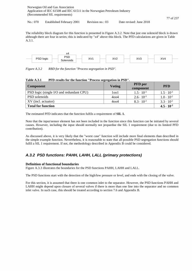
Norwegian Oil and Gas Association Application of IEC 61508 and IEC 61511 in the Norwegian Petroleum Industry (Recommended SIL requirements) No.: 070 Established February 2001 Revision no.: 03 Date revised: June 2018
77 of 237
The reliability block diagram for this function is presented in Figure A.3.2. Note that just one solenoid block is drawn although there are four in series; this is indicated by "x4" above this block. The PFD calculations are given in Table A.3.1.
PSD logic PSD Solenoids XV1 XV2 XV3 XV4
x4
Figure A.3.2 RBD for the function "Process segregation in PSD". Table A.3.1 PFD results for the function "Process segregation in PSD".
Component Voting PFD per component PFD
PSD logic (single I/O and redundant CPU) 1oo1 1.5 ⋅ 10-3 1.5 ⋅ 10-3 PSD solenoids 4oo4 2.6 ⋅ 10-3 1.0 ⋅ 10-2 XV (incl. actuator) 4oo4 8.3 ⋅ 10-3 3.3 ⋅ 10-2 Total for function 4.5 ⋅ 10-2
The estimated PFD indicates that the function fulfils a requirement of SIL 1. Note that the input/sensor element has not been included in the function since this function can be initiated by several causes. However, including the input should normally not jeopardise the SIL 1 requirement (due to its limited PFD contribution). As discussed above, it is very likely that the "worst case" function will include more final elements than described in the simple example function. Nevertheless, it is reasonable to state that all possible PSD segregation functions should fulfil a SIL 1 requirement. If not, the methodology described in Appendix B could be considered.
A.3.2 PSD functions: PAHH, LAHH, LALL (primary protections) Definition of functional boundaries Figure A.3.3 illustrates the boundaries for the PSD functions PAHH, LAHH and LALL. The PSD functions start with the detection of the high/low pressure or level, and ends with the closing of the valve. For this section, it is assumed that there is one common inlet to the separator. However, the PSD functions PAHH and LAHH might depend upon closure of several valves if there is more than one line into the separator and no common inlet valve. In such case, this should be treated according to section 7.6 and Appendix B.
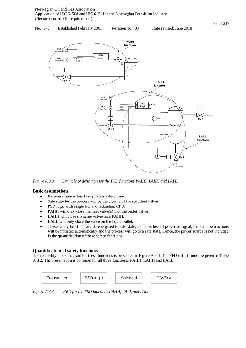
Norwegian Oil and Gas Association Application of IEC 61508 and IEC 61511 in the Norwegian Petroleum Industry (Recommended SIL requirements) No.: 070 Established February 2001 Revision no.: 03 Date revised: June 2018
78 of 237
PT
PSDsolenoide
ESV 1Separator
ESDsolenoide
PSDLogic IO
ESDlogic
LT
PSDsolenoide
ESV 1Separator
XV 2
XV 3
ESDsolenoide
PSDLogic IO
ESDlogic
PAHHfunction
LAHHfunction
LALLfunction
Figure A.3.3 Example of definition for the PSD functions PAHH, LAHH and LALL. Basic assumptions
• Response time is less than process safety time. • Safe state for the process will be the closure of the specified valves. • PSD logic with single I/O and redundant CPU. • PAHH will only close the inlet valve(s), not the outlet valves. • LAHH will close the same valves as a PAHH. • LALL will only close the valve on the liquid outlet. • These safety functions are de-energized to safe state, i.e. upon loss of power or signal, the shutdown actions
will be initiated automatically and the process will go to a safe state. Hence, the power source is not included in the quantification of these safety functions.
Quantification of safety functions The reliability block diagram for these functions is presented in Figure A.3.4. The PFD calculations are given in Table A.3.2. The presentation is common for all three functions: PAHH, LAHH and LALL.
Transmitter PSD logic Solenoid ESV/XV
Figure A.3.4 RBD for the PSD functions PAHH, PALL and LALL.
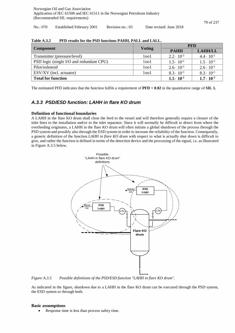
Norwegian Oil and Gas Association Application of IEC 61508 and IEC 61511 in the Norwegian Petroleum Industry (Recommended SIL requirements) No.: 070 Established February 2001 Revision no.: 03 Date revised: June 2018
79 of 237
Table A.3.2 PFD results for the PSD functions PAHH, PALL and LALL.
Component Voting PFD PAHH LAHH/LL
Transmitter (pressure/level) 1oo1 2.2 ⋅ 10-3 4.4 ⋅ 10-3 PSD logic (single I/O and redundant CPU) 1oo1 1.5 ⋅ 10-3 1.5 ⋅ 10-3 Pilot/solenoid 1oo1 2.6 ⋅ 10-3 2.6 ⋅ 10-3 ESV/XV (incl. actuator) 1oo1 8.3 ⋅ 10-3 8.3 ⋅ 10-3 Total for function 1.5 ⋅ 10-2 1.7 ⋅ 10-2
The estimated PFD indicates that the function fulfils a requirement of PFD < 0.02 in the quantitative range of SIL 1.
A.3.3 PSD/ESD function: LAHH in flare KO drum Definition of functional boundaries A LAHH in the flare KO drum shall close the feed to the vessel and will therefore generally require a closure of the inlet lines to the installation and/or to the inlet separator. Since it will normally be difficult to detect from where the overfeeding originates, a LAHH in the flare KO drum will often initiate a global shutdown of the process through the PSD system and possibly also through the ESD system in order to increase the reliability of the function. Consequently, a generic definition of the function LAHH in flare KO drum with respect to what is actually shut down is difficult to give, and rather the function is defined in terms of the detection device and the processing of the signal, i.e. as illustrated in Figure A.3.5 below.
LT1
Flare KOdrum
PSDLogic
LT2
ESDLogic
Signalout
Signalout
Possible"LAHH in flare KO drum"
definitions
Figure A.3.5 Possible definitions of the PSD/ESD function "LAHH in flare KO drum". As indicated in the figure, shutdown due to a LAHH in the flare KO drum can be executed through the PSD system, the ESD system or through both. Basic assumptions
• Response time is less than process safety time.
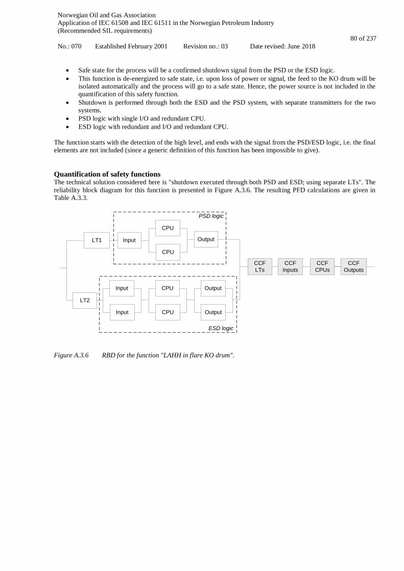
Norwegian Oil and Gas Association Application of IEC 61508 and IEC 61511 in the Norwegian Petroleum Industry (Recommended SIL requirements) No.: 070 Established February 2001 Revision no.: 03 Date revised: June 2018
80 of 237
• Safe state for the process will be a confirmed shutdown signal from the PSD or the ESD logic. • This function is de-energized to safe state, i.e. upon loss of power or signal, the feed to the KO drum will be
isolated automatically and the process will go to a safe state. Hence, the power source is not included in the quantification of this safety function.
• Shutdown is performed through both the ESD and the PSD system, with separate transmitters for the two systems.
• PSD logic with single I/O and redundant CPU. • ESD logic with redundant and I/O and redundant CPU.
The function starts with the detection of the high level, and ends with the signal from the PSD/ESD logic, i.e. the final elements are not included (since a generic definition of this function has been impossible to give). Quantification of safety functions The technical solution considered here is "shutdown executed through both PSD and ESD; using separate LTs". The reliability block diagram for this function is presented in Figure A.3.6. The resulting PFD calculations are given in Table A.3.3.
LT1
LT2
CCFLTs
CPU
CPU
Input Output
Input
Input
CPU
CPU
Output
Output
CCFInputs
CCFCPUs
CCFOutputs
PSD logic
ESD logic
Figure A.3.6 RBD for the function "LAHH in flare KO drum".
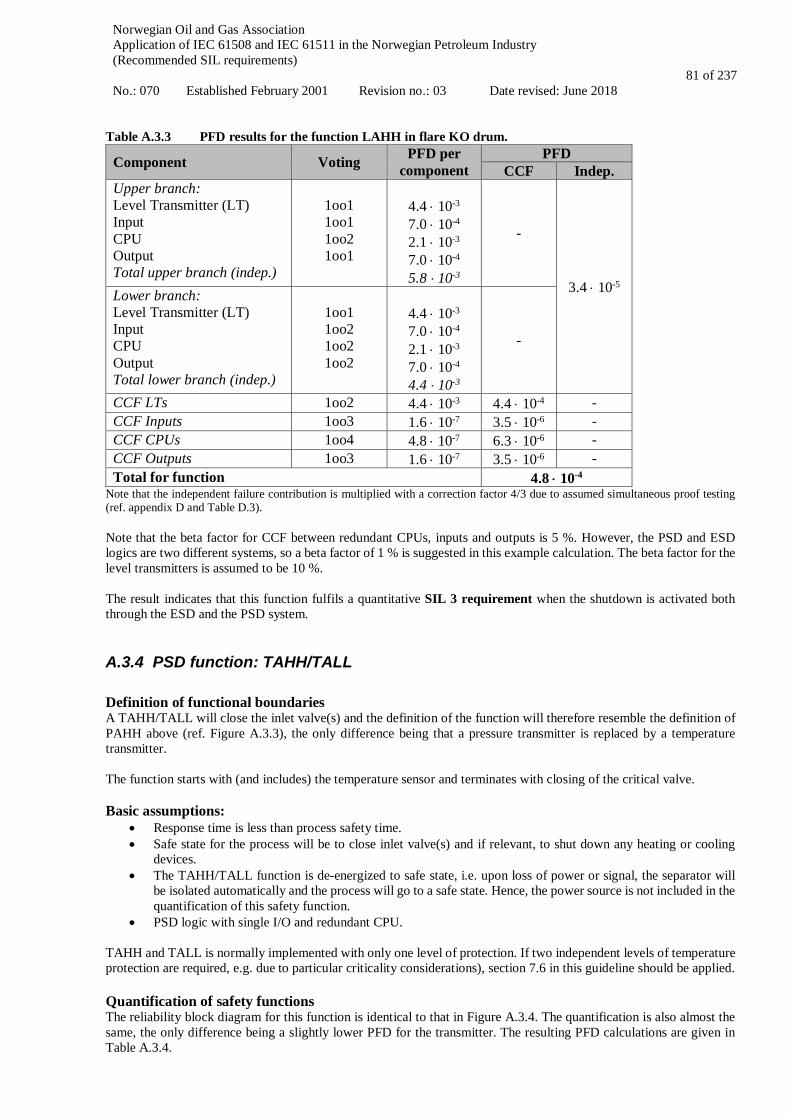
Norwegian Oil and Gas Association Application of IEC 61508 and IEC 61511 in the Norwegian Petroleum Industry (Recommended SIL requirements) No.: 070 Established February 2001 Revision no.: 03 Date revised: June 2018
81 of 237
Table A.3.3 PFD results for the function LAHH in flare KO drum.
Component Voting PFD per component
PFD CCF Indep.
Upper branch: Level Transmitter (LT) Input CPU Output Total upper branch (indep.)
1oo1 1oo1 1oo2 1oo1
4.4 ⋅ 10-3
7.0 ⋅ 10-4
2.1 ⋅ 10-3
7.0 ⋅ 10-4
5.8 ⋅ 10-3
-
3.4 ⋅ 10-5 Lower branch: Level Transmitter (LT) Input CPU Output Total lower branch (indep.)
1oo1 1oo2 1oo2 1oo2
4.4 ⋅ 10-3
7.0 ⋅ 10-4
2.1 ⋅ 10-3
7.0 ⋅ 10-4
4.4 ⋅ 10-3
-
CCF LTs 1oo2 4.4 ⋅ 10-3 4.4 ⋅ 10-4 - CCF Inputs 1oo3 1.6 ⋅ 10-7 3.5 ⋅ 10-6 - CCF CPUs 1oo4 4.8 ⋅ 10-7 6.3 ⋅ 10-6 - CCF Outputs 1oo3 1.6 ⋅ 10-7 3.5 ⋅ 10-6 - Total for function 4.8 ⋅ 10-4
Note that the independent failure contribution is multiplied with a correction factor 4/3 due to assumed simultaneous proof testing (ref. appendix D and Table D.3). Note that the beta factor for CCF between redundant CPUs, inputs and outputs is 5 %. However, the PSD and ESD logics are two different systems, so a beta factor of 1 % is suggested in this example calculation. The beta factor for the level transmitters is assumed to be 10 %. The result indicates that this function fulfils a quantitative SIL 3 requirement when the shutdown is activated both through the ESD and the PSD system.
A.3.4 PSD function: TAHH/TALL Definition of functional boundaries A TAHH/TALL will close the inlet valve(s) and the definition of the function will therefore resemble the definition of PAHH above (ref. Figure A.3.3), the only difference being that a pressure transmitter is replaced by a temperature transmitter. The function starts with (and includes) the temperature sensor and terminates with closing of the critical valve. Basic assumptions:
• Response time is less than process safety time. • Safe state for the process will be to close inlet valve(s) and if relevant, to shut down any heating or cooling
devices. • The TAHH/TALL function is de-energized to safe state, i.e. upon loss of power or signal, the separator will
be isolated automatically and the process will go to a safe state. Hence, the power source is not included in the quantification of this safety function.
• PSD logic with single I/O and redundant CPU.
TAHH and TALL is normally implemented with only one level of protection. If two independent levels of temperature protection are required, e.g. due to particular criticality considerations), section 7.6 in this guideline should be applied. Quantification of safety functions The reliability block diagram for this function is identical to that in Figure A.3.4. The quantification is also almost the same, the only difference being a slightly lower PFD for the transmitter. The resulting PFD calculations are given in Table A.3.4.
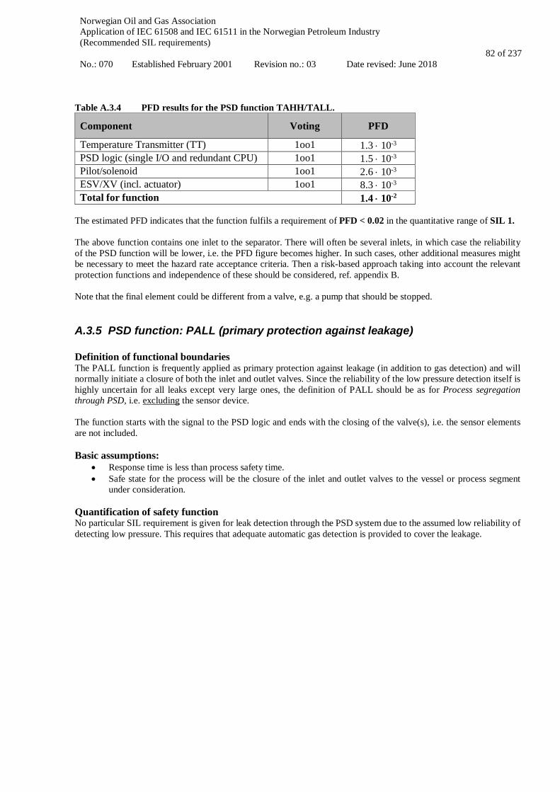
Norwegian Oil and Gas Association Application of IEC 61508 and IEC 61511 in the Norwegian Petroleum Industry (Recommended SIL requirements) No.: 070 Established February 2001 Revision no.: 03 Date revised: June 2018
82 of 237
Table A.3.4 PFD results for the PSD function TAHH/TALL.
Component Voting PFD
Temperature Transmitter (TT) 1oo1 1.3 ⋅ 10-3 PSD logic (single I/O and redundant CPU) 1oo1 1.5 ⋅ 10-3 Pilot/solenoid 1oo1 2.6 ⋅ 10-3 ESV/XV (incl. actuator) 1oo1 8.3 ⋅ 10-3 Total for function 1.4 ⋅ 10-2
The estimated PFD indicates that the function fulfils a requirement of PFD < 0.02 in the quantitative range of SIL 1. The above function contains one inlet to the separator. There will often be several inlets, in which case the reliability of the PSD function will be lower, i.e. the PFD figure becomes higher. In such cases, other additional measures might be necessary to meet the hazard rate acceptance criteria. Then a risk-based approach taking into account the relevant protection functions and independence of these should be considered, ref. appendix B. Note that the final element could be different from a valve, e.g. a pump that should be stopped.
A.3.5 PSD function: PALL (primary protection against leakage) Definition of functional boundaries The PALL function is frequently applied as primary protection against leakage (in addition to gas detection) and will normally initiate a closure of both the inlet and outlet valves. Since the reliability of the low pressure detection itself is highly uncertain for all leaks except very large ones, the definition of PALL should be as for Process segregation through PSD, i.e. excluding the sensor device. The function starts with the signal to the PSD logic and ends with the closing of the valve(s), i.e. the sensor elements are not included. Basic assumptions:
• Response time is less than process safety time. • Safe state for the process will be the closure of the inlet and outlet valves to the vessel or process segment
under consideration. Quantification of safety function No particular SIL requirement is given for leak detection through the PSD system due to the assumed low reliability of detecting low pressure. This requires that adequate automatic gas detection is provided to cover the leakage.
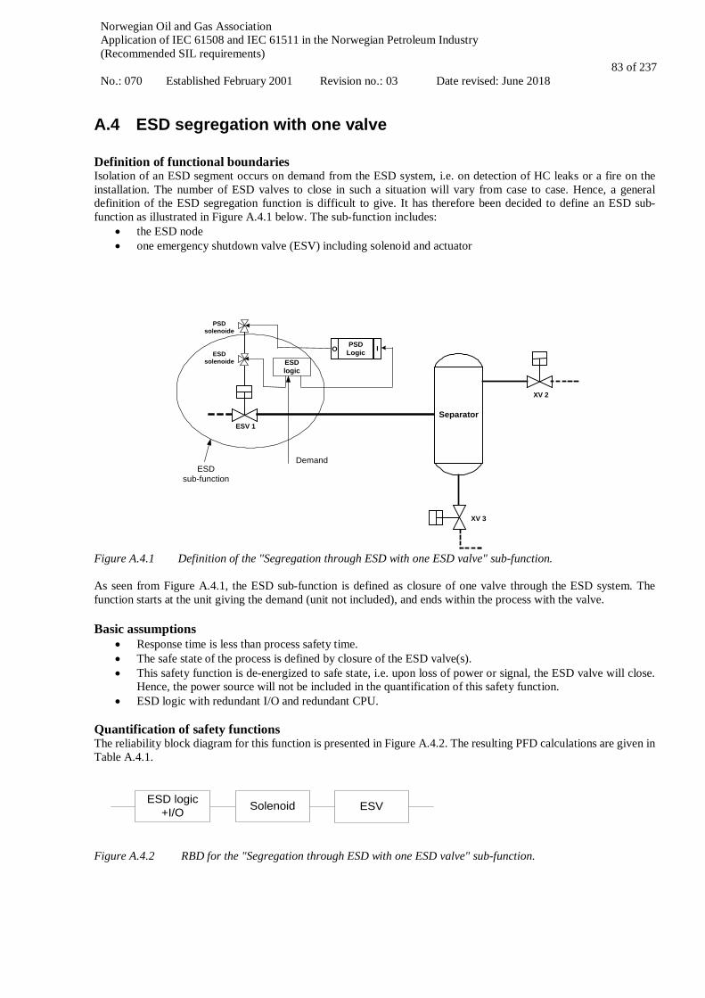
Norwegian Oil and Gas Association Application of IEC 61508 and IEC 61511 in the Norwegian Petroleum Industry (Recommended SIL requirements) No.: 070 Established February 2001 Revision no.: 03 Date revised: June 2018
83 of 237
A.4 ESD segregation with one valve Definition of functional boundaries Isolation of an ESD segment occurs on demand from the ESD system, i.e. on detection of HC leaks or a fire on the installation. The number of ESD valves to close in such a situation will vary from case to case. Hence, a general definition of the ESD segregation function is difficult to give. It has therefore been decided to define an ESD sub-function as illustrated in Figure A.4.1 below. The sub-function includes:
• the ESD node • one emergency shutdown valve (ESV) including solenoid and actuator
PSDsolenoide
ESV 1Separator
XV 2
XV 3
ESDsolenoide
PSDLogic IO
ESDlogic
ESDsub-function
Demand
Figure A.4.1 Definition of the "Segregation through ESD with one ESD valve" sub-function. As seen from Figure A.4.1, the ESD sub-function is defined as closure of one valve through the ESD system. The function starts at the unit giving the demand (unit not included), and ends within the process with the valve. Basic assumptions
• Response time is less than process safety time. • The safe state of the process is defined by closure of the ESD valve(s). • This safety function is de-energized to safe state, i.e. upon loss of power or signal, the ESD valve will close.
Hence, the power source will not be included in the quantification of this safety function. • ESD logic with redundant I/O and redundant CPU.
Quantification of safety functions The reliability block diagram for this function is presented in Figure A.4.2. The resulting PFD calculations are given in Table A.4.1.
Solenoid ESVESD logic +I/O
Figure A.4.2 RBD for the "Segregation through ESD with one ESD valve" sub-function.
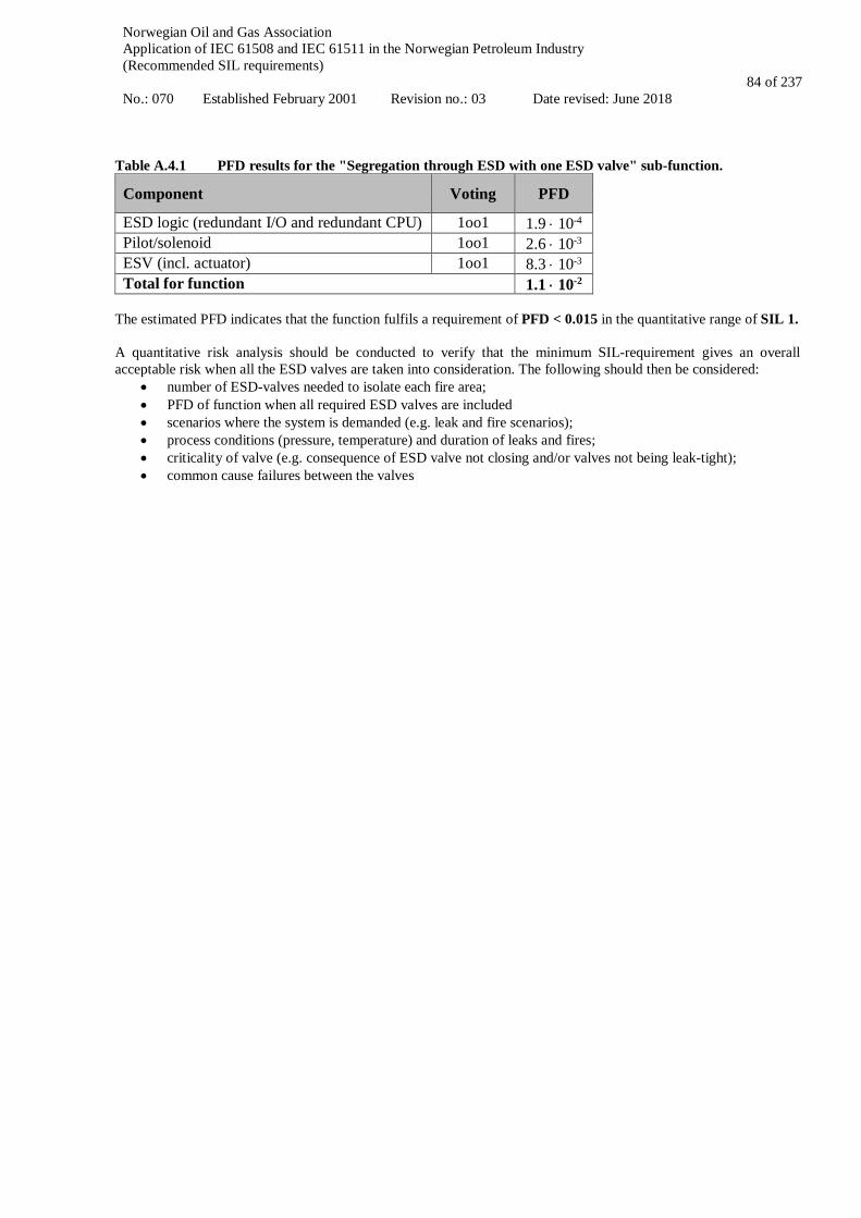
Norwegian Oil and Gas Association Application of IEC 61508 and IEC 61511 in the Norwegian Petroleum Industry (Recommended SIL requirements) No.: 070 Established February 2001 Revision no.: 03 Date revised: June 2018
84 of 237
Table A.4.1 PFD results for the "Segregation through ESD with one ESD valve" sub-function.
Component Voting PFD
ESD logic (redundant I/O and redundant CPU) 1oo1 1.9 ⋅ 10-4 Pilot/solenoid 1oo1 2.6 ⋅ 10-3 ESV (incl. actuator) 1oo1 8.3 ⋅ 10-3 Total for function 1.1 ⋅ 10-2
The estimated PFD indicates that the function fulfils a requirement of PFD < 0.015 in the quantitative range of SIL 1. A quantitative risk analysis should be conducted to verify that the minimum SIL-requirement gives an overall acceptable risk when all the ESD valves are taken into consideration. The following should then be considered:
• number of ESD-valves needed to isolate each fire area; • PFD of function when all required ESD valves are included • scenarios where the system is demanded (e.g. leak and fire scenarios); • process conditions (pressure, temperature) and duration of leaks and fires; • criticality of valve (e.g. consequence of ESD valve not closing and/or valves not being leak-tight); • common cause failures between the valves
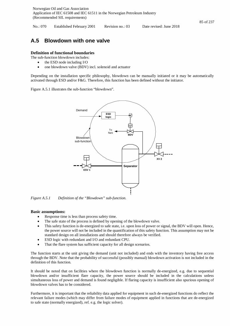
Norwegian Oil and Gas Association Application of IEC 61508 and IEC 61511 in the Norwegian Petroleum Industry (Recommended SIL requirements) No.: 070 Established February 2001 Revision no.: 03 Date revised: June 2018
85 of 237
A.5 Blowdown with one valve Definition of functional boundaries The sub-function blowdown includes:
• the ESD node including I/O • one blowdown valve (BDV) incl. solenoid and actuator
Depending on the installation specific philosophy, blowdown can be manually initiated or it may be automatically activated through ESD and/or F&G. Therefore, this function has been defined without the initiator. Figure A.5.1 illustrates the sub-function “blowdown”.
ESV 1Separator
XV 2
ESDlogic
BDV
Toflare
Blowdownsub-function
Demand
Figure A.5.1 Definition of the “Blowdown” sub-function. Basic assumptions:
• Response time is less than process safety time. • The safe state of the process is defined by opening of the blowdown valve. • This safety function is de-energized to safe state, i.e. upon loss of power or signal, the BDV will open. Hence,
the power source will not be included in the quantification of this safety function. This assumption may not be standard design on all installations and should therefore always be verified.
• ESD logic with redundant and I/O and redundant CPU. • That the flare system has sufficient capacity for all design scenarios.
The function starts at the unit giving the demand (unit not included) and ends with the inventory having free access through the BDV. Note that the probability of successful (possibly manual) blowdown activation is not included in the definition of this function. It should be noted that on facilities where the blowdown function is normally de-energized, e.g. due to sequential blowdown and/or insufficient flare capacity, the power source should be included in the calculations unless simultaneous loss of power and demand is found negligible. If flaring capacity is insufficient also spurious opening of blowdown valves has to be considered. Furthermore, it is important that the reliability data applied for equipment in such de-energized functions do reflect the relevant failure modes (which may differ from failure modes of equipment applied in functions that are de-energized to safe state (normally energized), ref. e.g. the logic solver).
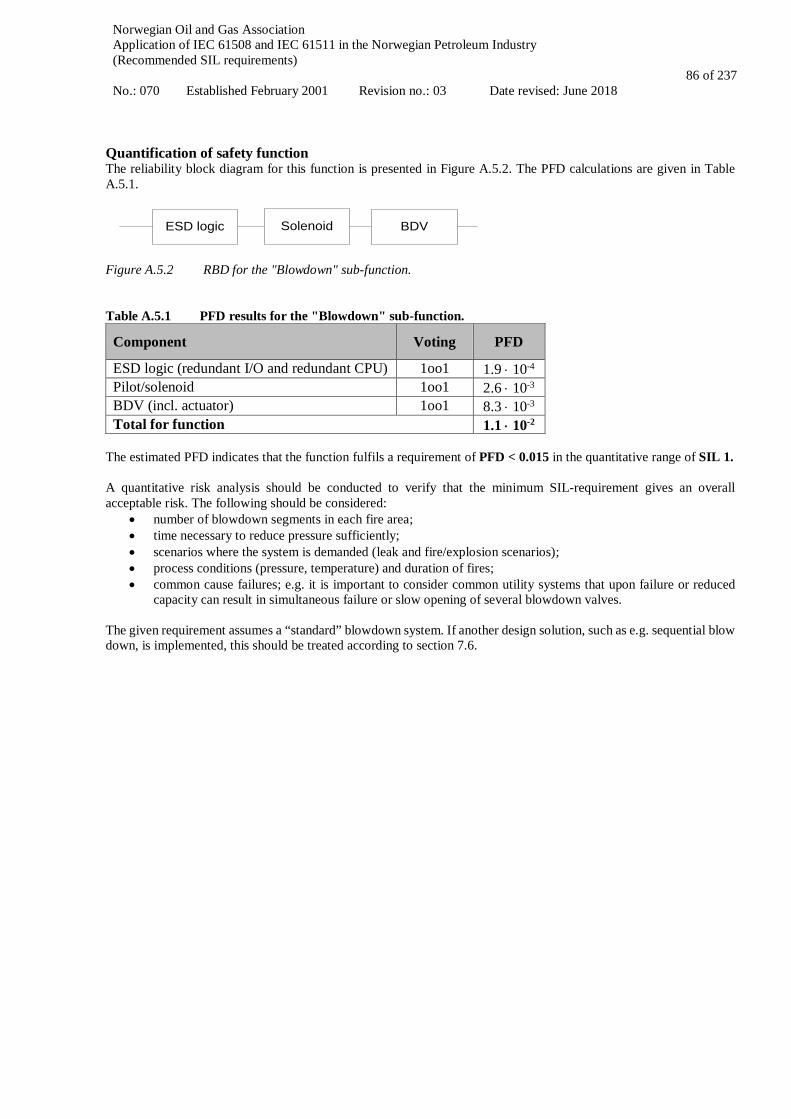
Norwegian Oil and Gas Association Application of IEC 61508 and IEC 61511 in the Norwegian Petroleum Industry (Recommended SIL requirements) No.: 070 Established February 2001 Revision no.: 03 Date revised: June 2018
86 of 237
Quantification of safety function The reliability block diagram for this function is presented in Figure A.5.2. The PFD calculations are given in Table A.5.1.
Solenoid BDVESD logic
Figure A.5.2 RBD for the "Blowdown" sub-function. Table A.5.1 PFD results for the "Blowdown" sub-function.
Component Voting PFD
ESD logic (redundant I/O and redundant CPU) 1oo1 1.9 ⋅ 10-4 Pilot/solenoid 1oo1 2.6 ⋅ 10-3 BDV (incl. actuator) 1oo1 8.3 ⋅ 10-3 Total for function 1.1 ⋅ 10-2
The estimated PFD indicates that the function fulfils a requirement of PFD < 0.015 in the quantitative range of SIL 1. A quantitative risk analysis should be conducted to verify that the minimum SIL-requirement gives an overall acceptable risk. The following should be considered:
• number of blowdown segments in each fire area; • time necessary to reduce pressure sufficiently; • scenarios where the system is demanded (leak and fire/explosion scenarios); • process conditions (pressure, temperature) and duration of fires; • common cause failures; e.g. it is important to consider common utility systems that upon failure or reduced
capacity can result in simultaneous failure or slow opening of several blowdown valves. The given requirement assumes a “standard” blowdown system. If another design solution, such as e.g. sequential blow down, is implemented, this should be treated according to section 7.6.

Norwegian Oil and Gas Association Application of IEC 61508 and IEC 61511 in the Norwegian Petroleum Industry (Recommended SIL requirements) No.: 070 Established February 2001 Revision no.: 03 Date revised: June 2018
87 of 237
A.6 Isolation of one topside well Definition of functional boundaries Isolation of one topside well is defined as the system needed to isolate one topside well. The following isolation functions have been considered in the present guideline:
• Section A.6.1: Isolation of production bore upon high pressure (shut in of one well from the PSD system upon high pressure).
• Section A.6.2: Isolation of production bore in one topside well from the production manifold/flowline. • Section A.6.3: Isolation of annulus in one topside gas lift well from the gas injection manifold/line (annulus is
connected to the reservoir below the DHSV). • Section A.6.4: Isolation of one chemical injection line in one topside well
o Isolation of one line of chemical injection with CIXT valve(s) between production master valve (PMV) or production wing valve (PWV) from reservoir backflow, e.g. MEG, corrosion / scale inhibitor, or
o Isolation of one downhole chemical injection line with CIDH valve(s) from reservoir backflow. All functions start at the input to the PSD or ESD system respectively, and end with at least one valve shutting in the well. Figure A.6.1 illustrates a simplified well schematic of the system and equipment relevant for the above functions.
AMV
DHSV
ASV
CIDH
PMV
PWVCIXT
Gas lift
PT
Choke
AWV
Figure A.6.1 Simplified well schematic (topside well) Basic assumptions (general for all isolation of topside well SIFs)
• Response time is less than process safety time. • The safe state of the process will be defined by closure of the valves and isolation of well.
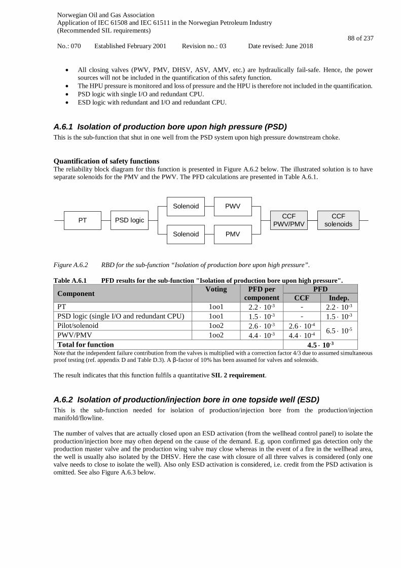
Norwegian Oil and Gas Association Application of IEC 61508 and IEC 61511 in the Norwegian Petroleum Industry (Recommended SIL requirements) No.: 070 Established February 2001 Revision no.: 03 Date revised: June 2018
88 of 237
• All closing valves (PWV, PMV, DHSV, ASV, AMV, etc.) are hydraulically fail-safe. Hence, the power sources will not be included in the quantification of this safety function.
• The HPU pressure is monitored and loss of pressure and the HPU is therefore not included in the quantification. • PSD logic with single I/O and redundant CPU. • ESD logic with redundant and I/O and redundant CPU.
A.6.1 Isolation of production bore upon high pressure (PSD) This is the sub-function that shut in one well from the PSD system upon high pressure downstream choke. Quantification of safety functions The reliability block diagram for this function is presented in Figure A.6.2 below. The illustrated solution is to have separate solenoids for the PMV and the PWV. The PFD calculations are presented in Table A.6.1.
CCFPWV/PMVPSD logic
PWV
PMV
SolenoidCCF
solenoidsSolenoid
PT
Figure A.6.2 RBD for the sub-function “Isolation of production bore upon high pressure”. Table A.6.1 PFD results for the sub-function "Isolation of production bore upon high pressure".
Component Voting PFD per component
PFD CCF Indep.
PT 1oo1 2.2 ⋅ 10-3 - 2.2 ⋅ 10-3 PSD logic (single I/O and redundant CPU) 1oo1 1.5 ⋅ 10-3 - 1.5 ⋅ 10-3 Pilot/solenoid 1oo2 2.6 ⋅ 10-3 2.6 ⋅ 10-4 6.5 ⋅ 10-5 PWV/PMV 1oo2 4.4 ⋅ 10-3 4.4 ⋅ 10-4 Total for function 4.5 ⋅ 10-3
Note that the independent failure contribution from the valves is multiplied with a correction factor 4/3 due to assumed simultaneous proof testing (ref. appendix D and Table D.3). A β-factor of 10% has been assumed for valves and solenoids. The result indicates that this function fulfils a quantitative SIL 2 requirement.
A.6.2 Isolation of production/injection bore in one topside well (ESD) This is the sub-function needed for isolation of production/injection bore from the production/injection manifold/flowline. The number of valves that are actually closed upon an ESD activation (from the wellhead control panel) to isolate the production/injection bore may often depend on the cause of the demand. E.g. upon confirmed gas detection only the production master valve and the production wing valve may close whereas in the event of a fire in the wellhead area, the well is usually also isolated by the DHSV. Here the case with closure of all three valves is considered (only one valve needs to close to isolate the well). Also only ESD activation is considered, i.e. credit from the PSD activation is omitted. See also Figure A.6.3 below.

Norwegian Oil and Gas Association Application of IEC 61508 and IEC 61511 in the Norwegian Petroleum Industry (Recommended SIL requirements) No.: 070 Established February 2001 Revision no.: 03 Date revised: June 2018
89 of 237
Productionmanifold
DHSV
To inlet separator
PMV
PWV
PSD node(wellhead
control panel)
”Isolation of well”Sub-function
HPUESD demand
ESD node
Figure A.6.3 Definition of the sub-function “Isolation of production/injection bore in one topside well”. Note to Figure A.6.3: Often the signals from the ESD and PSD nodes are routed via a Wellhead Control System (WCS) before being transferred to the wellhead valves. The function will then include another logic solver and the associated RBD should in such case be extended. Quantification of safety function The quantifications assume common cause failure between the PMV and the PWV and between the solenoids for the PMV, PWV and DHSV. The reliability block diagram for this function is presented in Figure A.6.4. The PFD calculations are given in Table A.6.2.
CCFPWV/PMV
PWV
PMV
Solenoid
Solenoid DHSV
CCFsolenoids
ESD logic
Figure A.6.4 RBD for the "Isolation of production/injection bore in one topside well" sub-function. Table A.6.2 PFD results for the "Isolation of production/injection bore in one topside well" sub-function.
Component Voting PFD per component
PFD CCF Indep.
ESD logic (redundant I/O and redundant CPU) 1oo1 1.9 ⋅ 10-4 - 1.9 ⋅ 10-4 Upper branch: PMV/PWV Solenoid
1oo1
2.6 ⋅ 10-3
-
9.5 ⋅ 10-5
PMV/PWV Total upper branch (indep.)
1oo2 4.4 ⋅ 10-3
7.0 ⋅ 10-3 4.4 ⋅ 10-4
4.4 ⋅ 10-4 Lower branch: DHSV Solenoid
1oo1
2.6 ⋅ 10-3
-
DHSV Total lower branch (indep.)
1oo1 7.0 ⋅ 10-3
9.6 ⋅ 10-3 -

Norwegian Oil and Gas Association Application of IEC 61508 and IEC 61511 in the Norwegian Petroleum Industry (Recommended SIL requirements) No.: 070 Established February 2001 Revision no.: 03 Date revised: June 2018
90 of 237
CCF solenoids 1oo2 - 2.6 ⋅ 10-4 - Total for function 5.5 ⋅ 10-4
Note that the independent failure contribution is multiplied with a correction factor 4/3 due to assumed simultaneous proof testing (ref. appendix D and Table D.3). A β-factor of 10% has been assumed for valves and solenoids and 5% for ESD logic. The result indicates that this function fulfils a quantitative SIL 3 requirement.
A.6.3 Isolation of annulus in one topside gas lift well This is the sub-function needed for isolation of annulus from the gas injection manifold/line in one topside gas lift well, i.e. in a well where the annulus is connected to the reservoir below the DHSV. Quantification of safety functions The reliability block diagram for this function is presented in Figure A.6.5. The illustrated solution is to have separate solenoids for the annulus safety valve (ASV) and the annulus master valve (AMV). The PFD calculations are presented in Table A.6.3. Note that the DHSV is not included in the present example since it is assumed that the gas lift valve connection is below the DHSV. If the gas lift valve is connected above the DHSV, then the DHSV could be considered as a redundant protection to the ASV and AMV.
CCFAnnulus valvesESD logic
ASV
AMVCCF
solenoids
Solenoid
AWVSolenoid
Figure A.6.5 RBD for the sub-function “Isolation of annulus in one topside gas lift well”. Table A.6.3 PFD results for the "Isolation of annulus in one topside gas lift well" sub-function.
Component Voting PFD per component
PFD CCF Indep.
ESD logic (redundant I/O and redundant CPU) 1oo1 1.9 ⋅ 10-4 - 1.9 ⋅ 10-4 Upper branch: ASV 1oo1 1.9 ⋅ 10-2 -
0.7 ⋅ 10-5
Lower branch: Solenoids AMV/AWV
1oo2 1oo2
2.6 ⋅ 10-3 4.4 ⋅ 10-3
(2.6 ⋅ 10-4) (See next row)
CCF annulus valves (AMV/AWV/ASV) 1oo3 4.4 ⋅ 10-3 (x2) 1.9 ⋅ 10-2 (x1) 3.5 ⋅ 10-4 -
Total for function 5.5 ⋅ 10-4 Note 1) The independent failure contribution from the valves is multiplied with a correction factor 4/3 due to assumed simultaneous proof testing (ref. appendix D and Table D.3). A β-factor of 10% has been assumed for valves and solenoids. Note 2) For estimating the CCF contribution from the annulus valves the geometric mean and the C1oo3 factor has been applied Note 3) Depending on the completion, the gas lift valve (GLV) downhole may be defined as a well barrier element with regular leak testing requirement. This may be accounted for as an additional redundancy if needed. The result indicates that this function fulfils a quantitative SIL 3 requirement.
A.6.4 Isolation of one chemical injection line in topside well This is the sub-function needed for isolation of reservoir pressure in one topside well from flowing back into one chemical injection line (see Figure A.6.1), i.e.

Norwegian Oil and Gas Association Application of IEC 61508 and IEC 61511 in the Norwegian Petroleum Industry (Recommended SIL requirements) No.: 070 Established February 2001 Revision no.: 03 Date revised: June 2018
91 of 237
• Isolation of chemical injection (e.g. MEG or corrosion / scale inhibitor ) line from reservoir backflow with CIXT valve connected between Production master valve (PMV) and Production wing valve (PWV), or
• Isolation of one downhole chemical injection line from reservoir backflow with CIDH valves. • Single chemical injection valves (CIXT and CIDH) is assumed
These two functions are similar and the RBD and PFD calculations are the same since we here assume that CIXT and CIDH have the same failure rates (as topside Xmas tree ESV). Also note that good design practise implies that one of the following is implemented(not included in the calculation):
• Redundant CIXT/CIDH • A testable downhole check valve / non-return valve (ref. Figure A.6.1) • Double block and bleed valves located at the wellhead (manually operated or operated from the control panel)
Note that isolation of PMV and DHSV has not been included for the purpose of simplification. Quantification of safety functions The reliability block diagram for this function is presented in Figure A.6.6. The PFD calculations are presented in Table A.6.4.
ESD logic CIXT/CIDHSolenoid
Figure A.6.6 RBD for the sub-function “Isolation of one line of chemical injection”. Table A.6.4 PFD results for the "Isolation of one line of chemical injection" sub-function.
Component Voting PFD
ESD logic (redundant I/O and redundant CPU) 1oo1 1.9 ⋅ 10-4 Pilot/solenoid 1oo1 2.6 ⋅ 10-3 CIXT (incl. actuator) 1oo1 4.4 ⋅ 10-3 Total for function 7.2 ⋅ 10-3
The results indicate that this function fulfils a quantitative SIL 2 requirement. Summary – Isolation of topside well Table A.6.5 summarizes the SIL requirements for the isolation of topside well functions. Table A.6.5 Summary of SIL requirements – Isolation of topside well functions
Function SIL requirement Isolation of one topside well upon high pressure (PSD) SIL 2 Isolation of production bore in one topside well (ESD) SIL 3 Isolation of annulus in one topside gas lift well (ESD) SIL 3 Isolation of one line of chemical injection in one topside well (ESD) SIL 2
A quantitative risk analysis should be conducted to verify that the minimum SIL-requirement gives an acceptable risk when the total number of wells is taken into consideration. The following should be considered:
• Number of wells; • Production / injection wells with or without gas-lift; • Wells in connection with workover / well intervention operations, such as wire line, coiled tubing, testing, etc. • Potential common cause failures between valves.

Norwegian Oil and Gas Association Application of IEC 61508 and IEC 61511 in the Norwegian Petroleum Industry (Recommended SIL requirements) No.: 070 Established February 2001 Revision no.: 03 Date revised: June 2018
92 of 237
A.7 ESD isolation of riser Definition of functional boundaries Isolation of the riser occurs upon a demand from the ESD system, i.e. on detection of HC leaks or fire on the installation. The sub-function isolation of riser is defined as the function needed to isolate one riser:
• the ESD node incl. I/O • one riser emergency shutdown valve (ESV) including solenoid and actuator
The sub-function starts at the unit where the demand is initiated (unit not included), and ends with the valve closing towards the riser. The sub-function is illustrated in Figure A.7.1.
Productionmanifold
RiserESV
To inletseparator
ESD logic
"isolation of riser"sub-function
Demand
Figure A.7.1 Definition of the sub-function “isolation of riser” Basic assumptions:
• Response time is less than process safety time. • The safe state of the process is closure of the riser ESD valve and isolation of the riser. • This safety function is de-energized to safe state, i.e. upon loss of power or signal, the ESD valve will close.
Hence, the power source will not be included in the quantification of this safety function. Since riser ESD valves are often large dimension double acting valves, this assumption should be considered for each specific case.
• ESD logic with redundant and I/O and redundant CPU. Quantification of safety functions The RBD and calculations will be exactly as for "Segregation through ESD", see Section A.4. Hence, the estimated PFD indicates that the function fulfils a requirement of PFD < 0.015 in the quantitative range of SIL 1. A quantitative risk analysis should be conducted to verify that the minimum SIL-requirement gives an overall acceptable risk. The following should be considered:
• scenarios where the system is demanded (e.g. leak and fire scenarios); • process conditions (pressure, temperature) and duration of leaks and fires; • criticality of valve (e.g. consequence of ESD valve not closing and/or valves not being leak-tight); • common cause failures between the valves

Norwegian Oil and Gas Association Application of IEC 61508 and IEC 61511 in the Norwegian Petroleum Industry (Recommended SIL requirements) No.: 070 Established February 2001 Revision no.: 03 Date revised: June 2018
93 of 237
A.8 Fire and gas detection
A.8.1 Fire detection with one detector Definition of functional boundaries The fire & gas detection system consists mainly of detectors and fire & gas logic solvers. Fire detection is generally based on three principles, i.e. smoke detection, heat detection and flame detection:
• For smoke detection the sub-function starts when the detector is exposed to smoke, and ends with the signal given from the F&G system.
• For heat detection the sub-function starts when the detector is exposed to heat/radiation, and ends with the signal given from the F&G system.
• For flame detection the sub-function starts when the detector area is exposed to flames, and ends with the signal given from the F&G system.
Note that the fire detection sub-function is defined in terms of one single detector. Basic assumptions:
• Response time is less than process safety time. • Safe state for the process will here be a signal from the F&G node. • This safety function is de-energized to safe state, i.e. upon loss of power or signal from the detector or the
F&G system; the described F&G actions will be activated. • F&G logic with single I/O and redundant CPU. • Fire detection panel (FDP) is not included in the below quantification, as it is assumed outside the functional
boundaries. When the FDP receives a fire alarm from the connected fire detector(s), the combined panels trigger the extinguishing process. For illustrative purposes the FDP is included (with dotted line) in the RBD in Figure A.8.1.
It should be noted that a large proportion of the fire detection systems in operation today (e.g. for smoke detectors), apply dedicated fire centrals. If a fire central or some other equipment is used to interface between the detector and the F&G, this has to be included in the calculations. This has not been done in the example calculations below. It should be noted that considerations related to the number of and layout of detectors should be covered by separate studies (e.g. simulation studies and QRA). Quantification of safety functions The reliability block diagram for this function is presented in Figure A.8.1. The resulting PFD calculations for the three cases, smoke detection, heat detection and flame detection are given in Table A.8.1.
Detector F&G logic FDP
Figure A.8.1 RBD for the "Fire detection" sub-function. Table A.8.1 PFD results for the "Fire detection" sub-function.
Component Voting PFD Smoke Heat Flame
Detector 1oo1 2.2 ⋅ 10-3 2.2 ⋅ 10-3 2.2 ⋅ 10-3 F&G logic (single I/O and redundant CPU) 1oo1 1.5 ⋅ 10-3 1.5 ⋅ 10-3 1.5 ⋅ 10-3 Total for function 3.7 ⋅ 10-3 3.7 ⋅ 10-3 3.7 ⋅ 10-3
The results indicate that each of these F&G functions fulfils a quantitative SIL 2 requirement. Analyses should be conducted to verify that the minimum SIL-requirement gives an overall acceptable risk when all fire detectors are taken into consideration. The following should be considered:
• number and placing of detectors in each area; • number of detectors that should actually function in a given fire scenario;
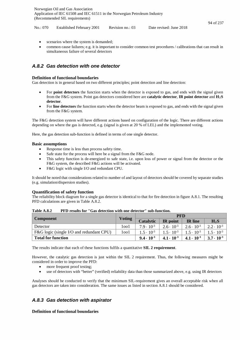
Norwegian Oil and Gas Association Application of IEC 61508 and IEC 61511 in the Norwegian Petroleum Industry (Recommended SIL requirements) No.: 070 Established February 2001 Revision no.: 03 Date revised: June 2018
94 of 237
• scenarios where the system is demanded; • common cause failures; e.g. it is important to consider common test procedures / calibrations that can result in
simultaneous failure of several detectors
A.8.2 Gas detection with one detector Definition of functional boundaries Gas detection is in general based on two different principles; point detection and line detection:
• For point detectors the function starts when the detector is exposed to gas, and ends with the signal given from the F&G system. Point gas detectors considered here are catalytic detector, IR point detector and H2S detector.
• For line detectors the function starts when the detector beam is exposed to gas, and ends with the signal given from the F&G system.
The F&G detection system will have different actions based on configuration of the logic. There are different actions depending on where the gas is detected, e.g. (signal is given at 20 % of LEL) and the implemented voting. Here, the gas detection sub-function is defined in terms of one single detector. Basic assumptions
• Response time is less than process safety time. • Safe state for the process will here be a signal from the F&G node. • This safety function is de-energized to safe state, i.e. upon loss of power or signal from the detector or the
F&G system, the described F&G actions will be activated. • F&G logic with single I/O and redundant CPU.
It should be noted that considerations related to number of and layout of detectors should be covered by separate studies (e.g. simulation/dispersion studies). Quantification of safety function The reliability block diagram for a single gas detector is identical to that for fire detection in figure A.8.1. The resulting PFD calculations are given in Table A.8.2. Table A.8.2 PFD results for "Gas detection with one detector" sub-function.
Component Voting PFD Catalytic IR point IR line H2S
Detector 1oo1 7.9 ⋅ 10-3 2.6 ⋅ 10-3 2.6 ⋅ 10-3 2.2 ⋅ 10-3 F&G logic (single I/O and redundant CPU) 1oo1 1.5 ⋅ 10-3 1.5 ⋅ 10-3 1.5 ⋅ 10-3 1.5 ⋅ 10-3 Total for function 9.4 ⋅ 10-3 4.1 ⋅ 10-3 4.1 ⋅ 10-3 3.7 ⋅ 10-3
The results indicate that each of these functions fulfils a quantitative SIL 2 requirement. However, the catalytic gas detection is just within the SIL 2 requirement. Thus, the following measures might be considered in order to improve the PFD:
• more frequent proof testing; • use of detectors with “better” (verified) reliability data than those summarized above, e.g. using IR detectors
Analyses should be conducted to verify that the minimum SIL-requirement gives an overall acceptable risk when all gas detectors are taken into consideration. The same issues as listed in section A.8.1 should be considered.
A.8.3 Gas detection with aspirator Definition of functional boundaries

Norwegian Oil and Gas Association Application of IEC 61508 and IEC 61511 in the Norwegian Petroleum Industry (Recommended SIL requirements) No.: 070 Established February 2001 Revision no.: 03 Date revised: June 2018
95 of 237
The flow detector (FALL) shall detect low flow of air aspiration, i.e. when the ambient air (and gas mixture) is prevented from reaching the detector, and it is the dangerous undetected failures of this flow detector which is critical. Thus, the fan, which provides continuous air flow, is not included in the RBD below. Also, the selector valve, which samples gas from defined spots, is not included in the RBD. Note that for some systems, instead of a fan, there is an ejector with instrument air for suction of ambient air in the enclosure (e.g. when difficult to access areas such as in turbine enclosures). Basic assumptions:
• Response time is less than process safety time. • Safe state for the process will here be a signal from the F&G node. • This safety function is de-energized to safe state, i.e. upon loss of power or signal from the detector or the
F&G system; the described F&G actions will be activated. • F&G logic with single I/O and redundant CPU. • Upon failure of the "aspiration" system, e.g., loss of instrument air /blockage in the suction line (e.g. closed
valve in the system) this will render detection impossible. FALL allows detecting failures related to insufficient air extract. Those "air extraction" failures will only remain undetected if the flow transmitter fails.
Quantification of safety function The reliability block diagram is given in Figure A.8.2 and the resulting PFD calculations are given in Table A.8.3. The quantifications are performed both with and without selector valve.
Detector F&G logicFTFanSelector valve
Figure A.8.2 RBD for the "Gas detection with aspirator" sub-function. Table A.8.3 PFD results for "Gas detection with aspirator" sub-function.
Component Voting PFD Catalytic IR point H2S
FT 1oo1 3.1 ⋅ 10-3 3.1 ⋅ 10-3 3.1 ⋅ 10-3 Detector 1oo1 7.9 ⋅ 10-3 2.6 ⋅ 10-3 2.2 ⋅ 10-3 F&G logic (single I/O and redundant CPU) 1oo1 1.5 ⋅ 10-3 1.5 ⋅ 10-3 1.5 ⋅ 10-3 Total for function 1.3 ⋅ 10-2 7.2 ⋅ 10-3 6.8 ⋅ 10-3
The results indicate that these functions fulfil a quantitative SIL 2 requirement for IR point gas detector and H2S detector. For catalytic gas detectors the estimated PFD is slightly higher than the SIL 2 range and the following measures should be considered in order to improve the PFD:
• more frequent proof testing; • use of detectors with “better” (verified) reliability data than those summarized in above, e.g. using IR detectors
Thus, a quantitative SIL 2 requirement is suggested for the sub-function "Gas detection with aspirator".
A.8.4 Start of fire pumps upon change of pressure or flow This sub-function starts the firewater pumps upon low pressure in the ring main or manual release of firewater. Firefighting systems may be activated locally from release station. Release feedback signal, such as pressure or flow transmitter when used to initiate emergency response action (e.g., automatic actions on HVAC – including initiation of ESD), with similarities to confirmed fire status, are defined as fire detection sub-function. This may include:
• Deluge (incl. monitor if used instead of deluge) release PT
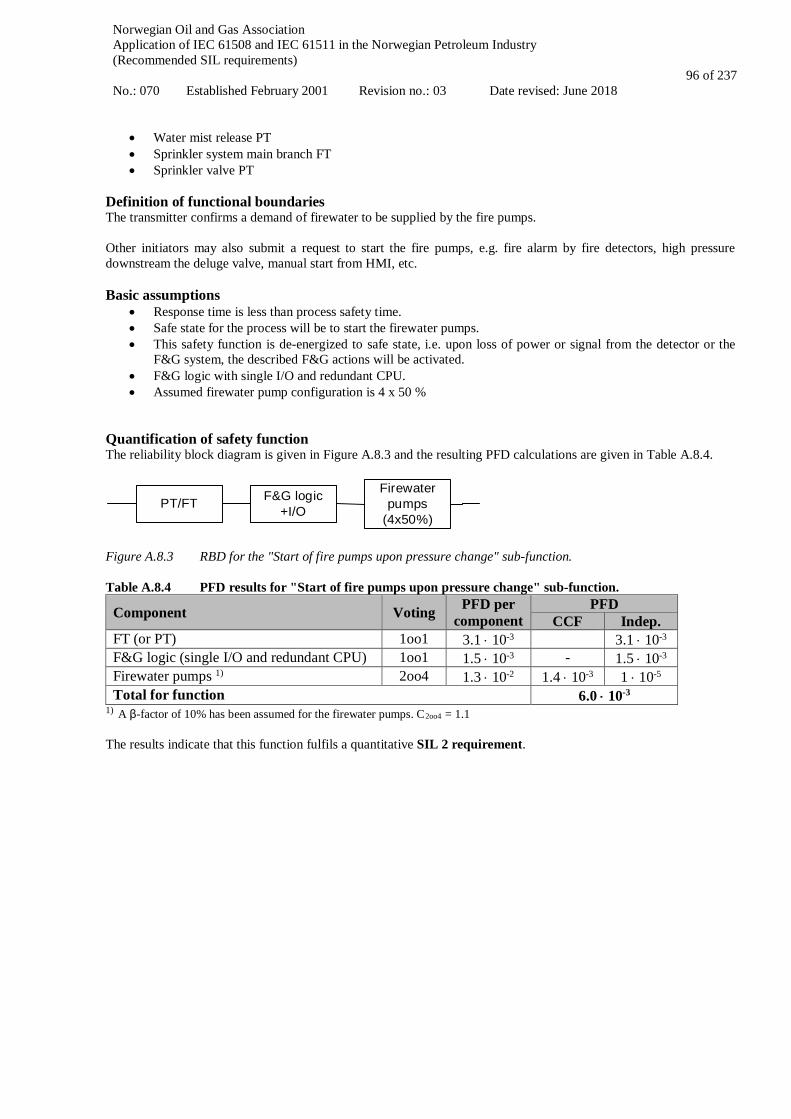
Norwegian Oil and Gas Association Application of IEC 61508 and IEC 61511 in the Norwegian Petroleum Industry (Recommended SIL requirements) No.: 070 Established February 2001 Revision no.: 03 Date revised: June 2018
96 of 237
• Water mist release PT • Sprinkler system main branch FT • Sprinkler valve PT
Definition of functional boundaries The transmitter confirms a demand of firewater to be supplied by the fire pumps. Other initiators may also submit a request to start the fire pumps, e.g. fire alarm by fire detectors, high pressure downstream the deluge valve, manual start from HMI, etc. Basic assumptions
• Response time is less than process safety time. • Safe state for the process will be to start the firewater pumps. • This safety function is de-energized to safe state, i.e. upon loss of power or signal from the detector or the
F&G system, the described F&G actions will be activated. • F&G logic with single I/O and redundant CPU. • Assumed firewater pump configuration is 4 x 50 %
Quantification of safety function The reliability block diagram is given in Figure A.8.3 and the resulting PFD calculations are given in Table A.8.4.
PT/FT F&G logic +I/O
Firewater pumps
(4x50%)
Figure A.8.3 RBD for the "Start of fire pumps upon pressure change" sub-function. Table A.8.4 PFD results for "Start of fire pumps upon pressure change" sub-function.
Component Voting PFD per component
PFD CCF Indep.
FT (or PT) 1oo1 3.1 ⋅ 10-3 3.1 ⋅ 10-3 F&G logic (single I/O and redundant CPU) 1oo1 1.5 ⋅ 10-3 - 1.5 ⋅ 10-3 Firewater pumps 1) 2oo4 1.3 ⋅ 10-2 1.4 ⋅ 10-3 1 ⋅ 10-5 Total for function 6.0 ⋅ 10-3
1) A β-factor of 10% has been assumed for the firewater pumps. C2oo4 = 1.1 The results indicate that this function fulfils a quantitative SIL 2 requirement.
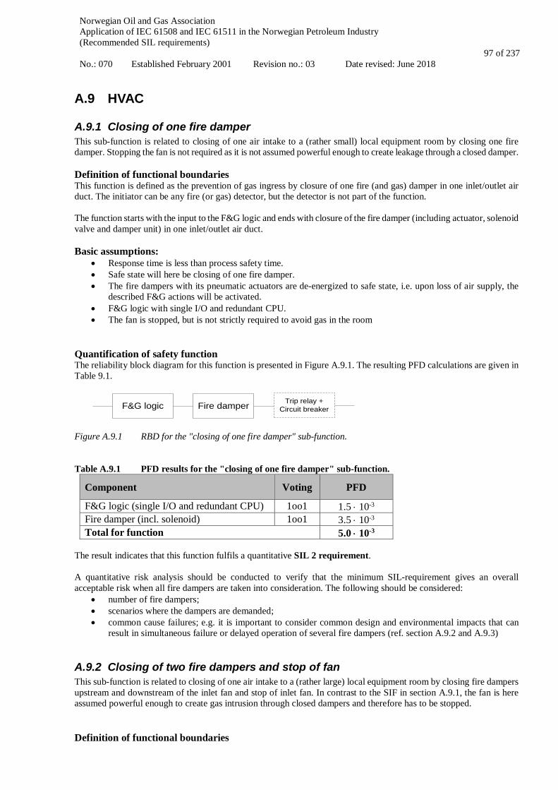
Norwegian Oil and Gas Association Application of IEC 61508 and IEC 61511 in the Norwegian Petroleum Industry (Recommended SIL requirements) No.: 070 Established February 2001 Revision no.: 03 Date revised: June 2018
97 of 237
A.9 HVAC
A.9.1 Closing of one fire damper This sub-function is related to closing of one air intake to a (rather small) local equipment room by closing one fire damper. Stopping the fan is not required as it is not assumed powerful enough to create leakage through a closed damper. Definition of functional boundaries This function is defined as the prevention of gas ingress by closure of one fire (and gas) damper in one inlet/outlet air duct. The initiator can be any fire (or gas) detector, but the detector is not part of the function. The function starts with the input to the F&G logic and ends with closure of the fire damper (including actuator, solenoid valve and damper unit) in one inlet/outlet air duct. Basic assumptions:
• Response time is less than process safety time. • Safe state will here be closing of one fire damper. • The fire dampers with its pneumatic actuators are de-energized to safe state, i.e. upon loss of air supply, the
described F&G actions will be activated. • F&G logic with single I/O and redundant CPU. • The fan is stopped, but is not strictly required to avoid gas in the room
Quantification of safety function The reliability block diagram for this function is presented in Figure A.9.1. The resulting PFD calculations are given in Table 9.1.
F&G logic Fire damper Trip relay + Circuit breaker
Figure A.9.1 RBD for the "closing of one fire damper" sub-function. Table A.9.1 PFD results for the "closing of one fire damper" sub-function.
Component Voting PFD
F&G logic (single I/O and redundant CPU) 1oo1 1.5 ⋅ 10-3 Fire damper (incl. solenoid) 1oo1 3.5 ⋅ 10-3 Total for function 5.0 ⋅ 10-3
The result indicates that this function fulfils a quantitative SIL 2 requirement. A quantitative risk analysis should be conducted to verify that the minimum SIL-requirement gives an overall acceptable risk when all fire dampers are taken into consideration. The following should be considered:
• number of fire dampers; • scenarios where the dampers are demanded; • common cause failures; e.g. it is important to consider common design and environmental impacts that can
result in simultaneous failure or delayed operation of several fire dampers (ref. section A.9.2 and A.9.3)
A.9.2 Closing of two fire dampers and stop of fan This sub-function is related to closing of one air intake to a (rather large) local equipment room by closing fire dampers upstream and downstream of the inlet fan and stop of inlet fan. In contrast to the SIF in section A.9.1, the fan is here assumed powerful enough to create gas intrusion through closed dampers and therefore has to be stopped. Definition of functional boundaries
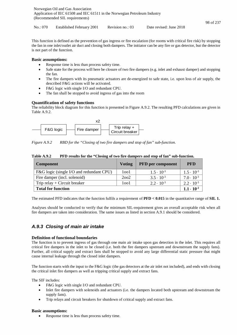
Norwegian Oil and Gas Association Application of IEC 61508 and IEC 61511 in the Norwegian Petroleum Industry (Recommended SIL requirements) No.: 070 Established February 2001 Revision no.: 03 Date revised: June 2018
98 of 237
This function is defined as the prevention of gas ingress or fire escalation (for rooms with critical fire risk) by stopping the fan in one inlet/outlet air duct and closing both dampers. The initiator can be any fire or gas detector, but the detector is not part of the function. Basic assumptions:
• Response time is less than process safety time. • Safe state for the process will here be closure of two fire dampers (e.g. inlet and exhaust damper) and stopping
the fan. • The fire dampers with its pneumatic actuators are de-energized to safe state, i.e. upon loss of air supply, the
described F&G actions will be activated. • F&G logic with single I/O and redundant CPU. • The fan shall be stopped to avoid ingress of gas into the room
Quantification of safety functions The reliability block diagram for this function is presented in Figure A.9.2. The resulting PFD calculations are given in Table A.9.2.
F&G logic Fire damper Trip relay + Circuit breaker
x2
Figure A.9.2 RBD for the “Closing of two fire dampers and stop of fan” sub-function. Table A.9.2 PFD results for the “Closing of two fire dampers and stop of fan” sub-function.
Component Voting PFD per component PFD
F&G logic (single I/O and redundant CPU) 1oo1 1.5 ⋅ 10-3 1.5 ⋅ 10-3 Fire damper (incl. solenoid) 2oo2 3.5 ⋅ 10-3 7.0 ⋅ 10-3 Trip relay + Circuit breaker 1oo1 2.2 ⋅ 10-3 2.2 ⋅ 10-3 Total for function 1.1 ⋅ 10-2
The estimated PFD indicates that the function fulfils a requirement of PFD < 0.015 in the quantitative range of SIL 1. Analyses should be conducted to verify that the minimum SIL-requirement gives an overall acceptable risk when all fire dampers are taken into consideration. The same issues as listed in section A.9.1 should be considered.
A.9.3 Closing of main air intake Definition of functional boundaries The function is to prevent ingress of gas through one main air intake upon gas detection in the inlet. This requires all critical fire dampers in the inlet to be closed (i.e. both the fire dampers upstream and downstream the supply fans). Further, all critical supply and extract fans shall be stopped to avoid any large differential static pressure that might cause internal leakage through the closed inlet dampers. The function starts with the input to the F&G logic (the gas detectors at the air inlet not included), and ends with closing the critical inlet fire dampers as well as tripping critical supply and extract fans. The SIF includes:
• F&G logic with single I/O and redundant CPU. • Inlet fire dampers with solenoids and actuators (i.e. the dampers located both upstream and downstream the
supply fans). • Trip relays and circuit breakers for shutdown of critical supply and extract fans.
Basic assumptions: • Response time is less than process safety time.

Norwegian Oil and Gas Association Application of IEC 61508 and IEC 61511 in the Norwegian Petroleum Industry (Recommended SIL requirements) No.: 070 Established February 2001 Revision no.: 03 Date revised: June 2018
99 of 237
• Location of main air intake is optimized to minimize the probability for HC gas exposure, taking into consideration factors such as prevailing wind direction and location of likely HC leak sources (ref. also NORSOK S-001 section 16.4.6).
• It is critical that the large HVAC fans are stopped in order to avoid any critical under-pressure (i.e. differential static pressure) with potential for causing leakage through closed dampers.
• Safe state for the process will be closure of all inlet fire dampers and tripping of all critical supply and extract fans.
• F&G logic with single I/O and redundant CPU. • The selected calculation example is assumed to be conservative since reflecting an HVAC inlet with all related
critical fire dampers and fans in 4oo4 configurations, ref. Figure A.23. • The fire dampers with its pneumatic actuators are de-energized to safe state, i.e. upon loss of air supply, the
described F&G actions will be activated. • Exhaust dampers are not included.
Quantification of safety functions The reliability block diagram for this function is presented in Figure A.9.3. The resulting PFD calculations are given in Table A.9.3.
F&G logic
Trip relay + circuit
breaker for supply fan
Upstream Fire damper
(incl. solenoid)
Downstream Fire damper
(incl. solenoid)
x4 x4
Trip relay + circuit
breaker for extract fan
x4 x4
Figure A.9.3 RBD for the “Closing of main air intake” sub-function. Table A.9.3 PFD results for the “Closing of main air intake” sub-function.
Component Voting PFD per component PFD
F&G logic (single I/O and redundant CPU) 1oo1 7.0 · 10-4 1.5 · 10-3 Upstream fire damper (incl. solenoid) 4oo4 3.5 · 10-3 1.4 · 10-2 Trip relay + circuit breaker for supply fan 4oo4 2.2 · 10-3 8.8 · 10-3 Downstream fire damper (incl. solenoid) 4oo4 3.5 · 10-3 1.4 · 10-2 Trip relay + circuit breaker for extract fan 4oo4 2.2 · 10-3 8.8 · 10-3 Total for function 4.7 · 10-2
The estimated PFD indicates that the function fulfils a requirement of PFD < 0.05 in the quantitative range of SIL 1. Analyses should be conducted to verify that the minimum SIL-requirement gives an overall acceptable risk when all air intakes are taken into consideration. The same issues as listed in section A.9.1 should be considered.
A.10 Electrical isolation Electrical isolation of ignition sources is typically initiated upon single HC gas detection, confirmed fire detection, high level in KO drum and manual ESD activation. Definition of functional boundaries The SIL-requirement applies for the subsystem needed for electrical isolation, i.e.:
• ESD logic • F&G logic • Circuit breakers / relays
The function starts at the unit initiating the demand (unit not included), and ends when all electrical ignition sources are isolated.

Norwegian Oil and Gas Association Application of IEC 61508 and IEC 61511 in the Norwegian Petroleum Industry (Recommended SIL requirements) No.: 070 Established February 2001 Revision no.: 03 Date revised: June 2018
100 of 237
Electrical isolation is normally executed through ESD, based on signal from F&G (exception may be non-essential equipment, representing only a few functions). Thus, also the ESD node shall be included in the SIL calculations. There are different actions depending on where the gas is detected. Basic assumptions:
• Response time is less than process safety time. • The safe state for the process will be to isolate all electric ignition sources. Hence, upon loss of power or
signal, all of the ignition sources will be automatically isolated. • Three circuit breakers are included in this typical function. Design of electrical isolation should aim at
minimizing the number of circuit breakers required to be activated. • ESD logic with redundant I/O and redundant CPU. • F&G logic with single I/O and redundant CPU.
This typical function may be applied for ignition source isolation of non-essential, essential and safety critical equipment. Different functions may need to be defined for each relevant isolation category. Quantification of safety function The reliability block diagram for this function is presented in Figure A.10.1, for the case of three circuit breakers. The resulting PFD calculations are given in Table A.10.1.
ESD logic
x3
Circuit breakerF&G logic
Figure A.10.1 RBD for the "Electrical Isolation" sub-function. Table A.10.1 PFD results for the “Electrical isolation” sub-function.
Component Voting PFD per component Total PFD
F&G logic (single I/O and redundant CPU) 1oo1 1.5 ⋅ 10-3 1.5 ⋅ 10-3 ESD logic (redundant I/O and redundant CPU) 1oo1 1.9 ⋅ 10-4 1.9 ⋅ 10-4 Circuit breaker 3oo3 1.3 ⋅ 10-3 3.9 ⋅ 10-3 Total for function 5.6 ⋅ 10-3
The result indicates that this function fulfils a quantitative SIL 2 requirement. Note that the above SIF typical includes the minimum number of circuit breakers / relays needed to isolate all applicable electric ignition sources. In order to achieve such a low number of circuit breakers / relays, an electrical design philosophy based on grouping (cf. NORSOK S-001) should be used. A quantitative risk analysis should be conducted to verify that the minimum SIL-requirement gives an overall acceptable risk. The following should be considered:
• which voting (kooN) of detection that gives electrical isolation of an area or shut down of main power; • number of circuit breakers; • scenarios where the system is demanded; • common cause failures; e.g. it is important to consider common design that can result in simultaneous failure
or delayed operation of several circuit breakers

Norwegian Oil and Gas Association Application of IEC 61508 and IEC 61511 in the Norwegian Petroleum Industry (Recommended SIL requirements) No.: 070 Established February 2001 Revision no.: 03 Date revised: June 2018
101 of 237
A.11 Firewater supply
A.11.1 Release of deluge Definition of functional boundaries The system boundaries include:
• F&G demand firewater • the firewater demand signal processed in the fire pump logic; • start of fire pumps; • opening of one deluge-valve (given confirmed fire)
The water intake, strainers, ring main, nozzles, etc. are not included in the calculations but are assumed covered by inspection and maintenance program to ensure availability. The function starts at the unit initiating the demand (unit not included), and ends with sufficient water flowing through the deluge valve. Basic assumptions:
• Response time is less than process safety time. • Safe state for the process will be release of firewater. • F&G logic with single I/O and redundant CPU. • Line monitoring is active on all safety I/O • The output from F&G logic starting the firewater pump is de-energize to start • The output from F&G logic opening the deluge valve is energize to open • This safety function will be normally de-energized, due to the inconvenience related to a spurious release of
firewater. It is therefore important that the UPS power supply for opening of the deluge valve is included in the calculations.
• the power supply from the UPS to the deluge valve will be continuously monitored (e.g. by routing the 24V supply into the F&G logic through a separate input card)
• upon loss of signal, an alarm will be given in the CCR, and compensating measures will be immediately initiated
Hence, a failure of the UPS power supply will have a very high degree of coverage (i.e. in IEC terms most of the UPS power supply failures become dangerous detected failures).
• Also, simultaneous loss of power and demand is assumed negligible. Therefore, for the purpose of the below example calculations, the same PFD figure has been used for the F&G logic as for functions that are de-energized to safe state.
• If any valves on the suction or discharge side of the firewater pumps are normally closed, the opening of these valves shall be included in the SIF and the corresponding SIL assessment.
• The firewater pump system has 4 x 50 % capacity for all relevant scenarios • The fire pumps fulfil the requirements in NFPA 20. • Manual opening of deluge valve at the skid is available as a compensating measure. • Each firewater pump is tested at least bi-weekly activated from the local panel (test mode), and yearly activated
from CCR During actual calculations/verifications it is important that these aspects are considered specifically for the facility under consideration. Furthermore, it should be verified that the reliability data applied for equipment in such de-energized functions do reflect the relevant failure modes (e.g. for the logic solver). Quantification of safety function The reliability block diagram for this function is presented in Figure A.11.1. The resulting PFD calculations are given in Table A.11.1. Note that included in the “FW pump” blocks are the firewater diesel engine, the generator, the electric motor and the pump itself.

Norwegian Oil and Gas Association Application of IEC 61508 and IEC 61511 in the Norwegian Petroleum Industry (Recommended SIL requirements) No.: 070 Established February 2001 Revision no.: 03 Date revised: June 2018
102 of 237
F&G logic
FW pump 1
FW pump 2
FW pump 3
FW pump 4
CCF FW pumps Deluge valve
Figure A.11.1 RBD for the "Firewater supply" sub-function. Table A.11.1 PFD results for the "Firewater supply" sub-function.
Component Voting PFD per component
PFD CCF Indep.
F&G logic (single I/O and redundant CPU) 1oo1 1.5 ⋅ 10-3 - 1.5 ⋅ 10-3 Firewater pumps 1) 2oo4 1.3 ⋅ 10-2 1.4 ⋅ 10-3 1 ⋅ 10-5 Deluge valve 1oo1 5.7 ⋅ 10-3 - 5.7 ⋅ 10-3 Total for function 8.6 ⋅ 10-3
1) A β-factor of 10% has been assumed for the firewater pumps. C2oo4 = 1.1 The result indicates that this function fulfils a quantitative SIL 2 requirement. However, the function is not far from a SIL 1 level. Thus, the following measures might be considered in order to improve the PFD for the function:
• more frequent proof testing of the logic and/or the deluge valve; • use of equipment with “better” (qualified) reliability data than those summarized in section A.2;
A quantitative risk analysis should be conducted to verify that the minimum SIL-requirement gives an overall acceptable risk. The following aspects should be considered:
• number of fire pumps; • number of deluge valves that have to open to cover the area(s) • scenarios where the system is demanded; • potential common cause failures and dependencies between the firewater pumps
A.11.2 Release of Inergen Definition of functional boundaries The function is to release Inergen for fire extinguishing in a dedicated room/enclosure upon signal from F&G. The function starts with the input to the F&G logic (the F&G detectors not included), and ends with opening of the Inergen release valve. Included in the functions is F&G logic incl. I/O and one Inergen release valve incl. pilot/solenoid. Basic assumptions:
• Response time is less than process safety time. • Safe state for the process will be opening of the Inergen release valve upon signal from F&G logic. The related
F&G detectors are not included in this sub-function. • F&G logic with single I/O and redundant CPU. • The Inergen release valve is dependent on F&G signal/UPS power to operate (i.e. energize to trip), i.e. the
valve remain in position (fail maintain) upon loss of signal/power. It will however be possible to operate the valve manually.
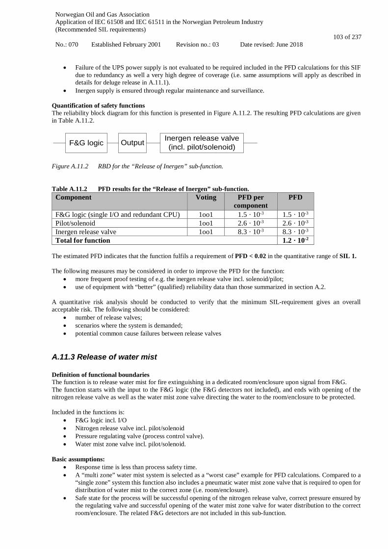
Norwegian Oil and Gas Association Application of IEC 61508 and IEC 61511 in the Norwegian Petroleum Industry (Recommended SIL requirements) No.: 070 Established February 2001 Revision no.: 03 Date revised: June 2018
103 of 237
• Failure of the UPS power supply is not evaluated to be required included in the PFD calculations for this SIF due to redundancy as well a very high degree of coverage (i.e. same assumptions will apply as described in details for deluge release in A.11.1).
• Inergen supply is ensured through regular maintenance and surveillance. Quantification of safety functions The reliability block diagram for this function is presented in Figure A.11.2. The resulting PFD calculations are given in Table A.11.2.
F&G logic Inergen release valve (incl. pilot/solenoid)Output
Figure A.11.2 RBD for the “Release of Inergen” sub-function. Table A.11.2 PFD results for the “Release of Inergen” sub-function.
Component Voting PFD per component
PFD
F&G logic (single I/O and redundant CPU) 1oo1 1.5 · 10-3 1.5 · 10-3 Pilot/solenoid 1oo1 2.6 · 10-3 2.6 · 10-3 Inergen release valve 1oo1 8.3 · 10-3 8.3 · 10-3 Total for function 1.2 · 10-2
The estimated PFD indicates that the function fulfils a requirement of PFD < 0.02 in the quantitative range of SIL 1. The following measures may be considered in order to improve the PFD for the function:
• more frequent proof testing of e.g. the inergen release valve incl. solenoid/pilot; • use of equipment with “better” (qualified) reliability data than those summarized in section A.2.
A quantitative risk analysis should be conducted to verify that the minimum SIL-requirement gives an overall acceptable risk. The following should be considered:
• number of release valves; • scenarios where the system is demanded; • potential common cause failures between release valves
A.11.3 Release of water mist Definition of functional boundaries The function is to release water mist for fire extinguishing in a dedicated room/enclosure upon signal from F&G. The function starts with the input to the F&G logic (the F&G detectors not included), and ends with opening of the nitrogen release valve as well as the water mist zone valve directing the water to the room/enclosure to be protected. Included in the functions is:
• F&G logic incl. I/O • Nitrogen release valve incl. pilot/solenoid • Pressure regulating valve (process control valve). • Water mist zone valve incl. pilot/solenoid.
Basic assumptions:
• Response time is less than process safety time. • A “multi zone” water mist system is selected as a “worst case” example for PFD calculations. Compared to a
“single zone” system this function also includes a pneumatic water mist zone valve that is required to open for distribution of water mist to the correct zone (i.e. room/enclosure).
• Safe state for the process will be successful opening of the nitrogen release valve, correct pressure ensured by the regulating valve and successful opening of the water mist zone valve for water distribution to the correct room/enclosure. The related F&G detectors are not included in this sub-function.
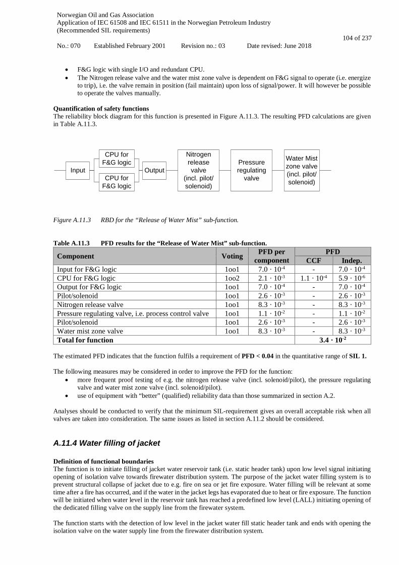
Norwegian Oil and Gas Association Application of IEC 61508 and IEC 61511 in the Norwegian Petroleum Industry (Recommended SIL requirements) No.: 070 Established February 2001 Revision no.: 03 Date revised: June 2018
104 of 237
• F&G logic with single I/O and redundant CPU. • The Nitrogen release valve and the water mist zone valve is dependent on F&G signal to operate (i.e. energize
to trip), i.e. the valve remain in position (fail maintain) upon loss of signal/power. It will however be possible to operate the valves manually.
Quantification of safety functions The reliability block diagram for this function is presented in Figure A.11.3. The resulting PFD calculations are given in Table A.11.3.
CPU for F&G logic Water Mist
zone valve(incl. pilot/solenoid)
Nitrogen release valve
(incl. pilot/solenoid)
CPU for F&G logic
OutputInputPressure regulating
valve
Figure A.11.3 RBD for the “Release of Water Mist” sub-function. Table A.11.3 PFD results for the “Release of Water Mist” sub-function.
Component Voting PFD per component
PFD CCF Indep.
Input for F&G logic 1oo1 7.0 · 10-4 - 7.0 · 10-4 CPU for F&G logic 1oo2 2.1 · 10-3 1.1 · 10-4 5.9 · 10-6 Output for F&G logic 1oo1 7.0 · 10-4 - 7.0 · 10-4 Pilot/solenoid 1oo1 2.6 · 10-3 - 2.6 · 10-3 Nitrogen release valve 1oo1 8.3 · 10-3 - 8.3 · 10-3 Pressure regulating valve, i.e. process control valve 1oo1 1.1 · 10-2 - 1.1 · 10-2 Pilot/solenoid 1oo1 2.6 · 10-3 - 2.6 · 10-3 Water mist zone valve 1oo1 8.3 · 10-3 - 8.3 · 10-3 Total for function 3.4 · 10-2
The estimated PFD indicates that the function fulfils a requirement of PFD < 0.04 in the quantitative range of SIL 1. The following measures may be considered in order to improve the PFD for the function:
• more frequent proof testing of e.g. the nitrogen release valve (incl. solenoid/pilot), the pressure regulating valve and water mist zone valve (incl. solenoid/pilot).
• use of equipment with “better” (qualified) reliability data than those summarized in section A.2. Analyses should be conducted to verify that the minimum SIL-requirement gives an overall acceptable risk when all valves are taken into consideration. The same issues as listed in section A.11.2 should be considered.
A.11.4 Water filling of jacket Definition of functional boundaries The function is to initiate filling of jacket water reservoir tank (i.e. static header tank) upon low level signal initiating opening of isolation valve towards firewater distribution system. The purpose of the jacket water filling system is to prevent structural collapse of jacket due to e.g. fire on sea or jet fire exposure. Water filling will be relevant at some time after a fire has occurred, and if the water in the jacket legs has evaporated due to heat or fire exposure. The function will be initiated when water level in the reservoir tank has reached a predefined low level (LALL) initiating opening of the dedicated filling valve on the supply line from the firewater system. The function starts with the detection of low level in the jacket water fill static header tank and ends with opening the isolation valve on the water supply line from the firewater distribution system.

Norwegian Oil and Gas Association Application of IEC 61508 and IEC 61511 in the Norwegian Petroleum Industry (Recommended SIL requirements) No.: 070 Established February 2001 Revision no.: 03 Date revised: June 2018
105 of 237
Included in the functions is:
• Level transmitter (in water reservoir tank / static header tank) • F&G logic incl. I/O • Isolation valve (incl. actuator and pilot/solenoid) towards firewater distribution system.
Basic assumptions:
• Response time is less than process safety time. • Safe state for the process will be opening of the isolation valve towards firewater distribution system upon
detection of LALL in jacket water reservoir tank (i.e. static header tank). • F&G logic with single I/O and redundant CPU. • The firewater distribution system is functional. • The safety function is de-energize to safe state.
Quantification of safety functions The reliability block diagram for this function is presented in Figure A.11.4. The resulting PFD calculations are given in Table A.11.4.
F&G logic
Isolation valve (incl. actuator)
on firewater connection line
Pilot /solenoid
Level Transmiter
Figure A.11.4 RBD for the “Water filling of Jacket legs” sub-function Table A.11.4 PFD results for the “Water filling of Jacket legs” sub-function.
Component Voting PFD per component PFD CCF Indep.
Level transmitter 1oo1 4.4 · 10-3 - 4.4 · 10-3 Input for F&G logic 1oo1 7.0 · 10-4 - 7.0 · 10-4 CPU for F&G logic 1oo2 2.1 · 10-3 1.1 · 10-4 5.9 · 10-6 Output for F&G logic 1oo1 7.0 · 10-4 - 7.0 · 10-4 Pilot/solenoid 1oo1 2.6 · 10-3 - 2.6 · 10-3 ESV/XV (incl. actuator) 1oo1 8.3 · 10-3 - 8.3 · 10-3 Total for function 1.7 · 10-2
The estimated PFD indicates that the function fulfils a requirement of PFD < 0.02 in the quantitative range of SIL 1. The following measures may be considered in order to improve the PFD for the function:
• more frequent proof testing of e.g. the level transmitter and the actuated isolation valve incl. pilot/solenoid. • use of equipment with “better” (qualified) reliability data than those summarized in section A.2.
A quantitative risk analysis should be conducted to verify that the minimum SIL-requirement gives an overall acceptable risk. The following aspects should be considered:
• number and location of level transmitters • number of isolation valves required and number of functions required to provide protection; • scenarios where the system is demanded; • potential common cause failures and dependencies between the firewater pumps.
A.12 Ballasting
A.12.1 Start of ballast system

Norwegian Oil and Gas Association Application of IEC 61508 and IEC 61511 in the Norwegian Petroleum Industry (Recommended SIL requirements) No.: 070 Established February 2001 Revision no.: 03 Date revised: June 2018
106 of 237
Definition of functional boundaries The purpose of this function is rig re-establishment to restore acceptable inclination and draft after an accidental event. The function starts when the operator has demanded emptying of one ballast water tank, and ends when emptying of that tank has been initiated. The following equipment is involved in the sub-function, ref. Figure A.12.1: • Ballast node incl. I/O. • Inlet valve (including actuator, solenoid and valve). • Ballast control pump (2 x 100 %) incl. engine, generator and motor. • Discharge valve incl. (including actuator, solenoid and valve).
Inlet valve Dischargevalve
Pump B
Pump A
Tank valve
Tank valve
Tank valve
Tank valve
Figure A.12.1 Definition of the "Start of ballast system" sub-function. Basic assumptions:
• Response time is less than process safety time. • The valves are fail close and ballast control output signals are fail close/stop. • Safe state for the facility will be to start the ballast pumps in order to restore acceptable inclination and draft
after an accidental event. • Assumed proof test intervals are weekly for the pumps, six months for valves and 12 months for the ballast
control logic. • Ballast system with single I/O and redundant CPU. • Redundant (2x100%) ballast pumps. • In order to start the ballast pumps, the UPS power (and main electric supply) will be required;
• the power supply from the UPS to the control system will be continuously monitored (e.g. by routing the 24V supply into the ballast control logic through a separate input card);
• the power supply to the ballast pumps will also be continuously monitored (e.g. by routing the electric power supply into the ballast control logic through a separate input card);
• upon loss of signal, an alarm will be given in the CCR and compensating measures will be initiated immediately in case of an alarm.
Hence, power failure will have a very high degree of coverage (i.e. in IEC terms most of the power supply failures become dangerous detected failures). In addition, the actuators are energized for open position. Therefore, for the purpose of the below example calculations, the same PFD figure has been used for the logic as for functions that are de-energized to safe state.
• Simultaneous demand and loss of power is assumed negligible.

Norwegian Oil and Gas Association Application of IEC 61508 and IEC 61511 in the Norwegian Petroleum Industry (Recommended SIL requirements) No.: 070 Established February 2001 Revision no.: 03 Date revised: June 2018
107 of 237
• There might be situations when start of the ballast pumps is not desirable and this safety function is therefore energize-to-start. In such situations, simultaneous loss of power and demand is assumed negligible.
During actual calculations/verifications it is important that these aspects are considered specifically for the facility under consideration. Furthermore, it should be verified that the reliability data applied for equipment in such de-energized functions do reflect the relevant failure modes (e.g. for the logic solver). Quantification of safety function The reliability block diagram for this function is presented in Figure A.12.2. The resulting PFD calculations are given in Table A.12.1.
Pump ABallast system
incl. I/OPump B
CCFpumpsTank valve Discharge
valve
Figure A.12.2 RBD for the "Start of ballast system" sub-function. Table A.12.1 PFD results for the "Start of ballast system sub-function.
Component Voting PFD per component
PFD CCF Indep.
Ballast system (single I/O and redundant CPU) 1oo1 1.5 ⋅ 10-3 - 1.5 ⋅ 10-3 Tank valve incl. actuator and pilot/solenoid 1oo1 8.3 ⋅ 10-3 - 8.3 ⋅ 10-3 Ballast pumps 1) 1oo2 1.3 ⋅ 10-2 1.3 ⋅ 10-3 2.3 ⋅ 10-4 Discharge valve incl. actuator and pilot/solenoid 1oo1 8.3 ⋅ 10-3 - 8.3 ⋅ 10-3 Total for function 2.0 ⋅ 10-2
1) Assumed same figure as for “fail to start” for firewater pumps in deluge function. A β-factor of 10% has been assumed for the ballast pumps The estimated PFD indicates that the function fulfils a requirement of PFD < 0.02 in the quantitative range of SIL 1. It should be noted that the ballast system is run more or less continuously on a floating installation. Hence, it may be argued that the proof testing of the logic and the valves will be more frequent than the intervals assumed above. A quantitative risk analysis should be conducted to verify that the minimum SIL-requirement gives an overall acceptable risk. The following aspects should be considered:
• number of ballast pumps; • availability of power; • scenarios where the system is demanded; • potential common cause failures between the ballast pumps
A.12.2 Emergency stop of ballast system Definition of functional boundaries The Norwegian Maritime Directorate specifies that there shall be an additional emergency stop mechanism of the ballast system separate from the programmed ballast control functions to ensure a safe facility by closing all relevant valves and stopping all relevant pumps, i.e. the ballast control valves/pumps, and for installations with cargo storage, cargo handling valves/pumps as well. The sub-function starts when the operator has operated the emergency stop pushbutton, and ends when the ballast pump motor has stopped and the inlet valve and discharge valve have closed. The following equipment is included in the sub-function: The motor is tripped by circuit breakers and the solenoid and valve close upon loss of power.

Norwegian Oil and Gas Association Application of IEC 61508 and IEC 61511 in the Norwegian Petroleum Industry (Recommended SIL requirements) No.: 070 Established February 2001 Revision no.: 03 Date revised: June 2018
108 of 237
Basic Assumptions:
• Response time is less than process safety time. • Safe state for the installation will in this case be to stop the ballast pumps and close the inlet valve and the
discharge valve. • The sub-function will be independent of all utility systems since upon loss of power the function goes to a safe
state (i.e. relays and contactors will open and the valves will close). The emergency pushbutton is manual, operate-to-open.
Quantification of safety function The reliability block diagram for this function is presented in Figure A.12.3. The resulting PFD calculations are given in Table A.12.2.
Pushbutton Circuit breaker ValvePilot/Solenoid
x2 x2 x2
Figure A.12.3 RBD for the "Emergency stop of ballast system" sub-function. Table A.12.2 PFD results for "Emergency stop of ballast system" sub-function.
Component Voting PFD per component PFD
Pushbutton 1oo1 1.3 ⋅ 10-3 1.3 ⋅ 10-3 Circuit breaker 2oo2 1.3 ⋅ 10-3 2.6 ⋅ 10-3 Pilot/solenoid 2oo2 2.6 ⋅ 10-3 5.2 ⋅ 10-3 Valves (incl. actuator) 2oo2 8.3 ⋅ 10-3 1.7 ⋅ 10-2 Total for function 2.6 ⋅ 10-2
The estimated PFD indicates that the function fulfils a requirement of PFD < 0.03 in the quantitative range of SIL 1. A quantitative risk analysis should be conducted to verify that the minimum SIL-requirement gives an overall acceptable risk. The following should be considered:
• number of circuit breakers and valves required to function; • scenarios where the system is demanded; • common cause failures between the circuit breakers and between the valves.

Norwegian Oil and Gas Association Application of IEC 61508 and IEC 61511 in the Norwegian Petroleum Industry (Recommended SIL requirements) No.: 070 Established February 2001 Revision no.: 03 Date revised: June 2018
109 of 237
A.13 Isolation of one subsea well Definition of functional boundaries The following isolation functions have been considered for the isolation of one subsea well:
• Primary and secondary barrier isolation of production/injection bore in one subsea well • Secondary barrier isolation of annulus in one subsea gas lift well from the gas injection manifold/line • Secondary barrier isolation of one line of chemical injection in one subsea well • Secondary barrier isolation of one service line from one subsea well
Note: “primary” and “secondary” refer herein to well barrier, ref definitions in NORSOK D-010 In the above list, the function corresponding to primary and secondary barrier isolation (SIL3) rely upon the isolation of necessary XT valves and downhole valves (i.e. dual barrier isolation) by activation of both electrical power cut and high and low pressure hydraulic bleed-off from the HPU. This function is typically activated upon APS, fire and gas detection in riser area for wells located within the platform safety zone. The functions corresponding to secondary barrier isolation (SIL1-2) rely upon the isolation of necessary XT valves (i.e. single barrier isolation) which may be realized by activation of electrical power cut only. Activation is typically triggered upon fire and gas detection in riser area (for wells located away from platform safety zone). Bleed off of low pressure hydraulic from HPU has not included in the functions related to the isolation of X-mas tree valves only as this action is generally not required as part of a secondary/single barrier isolation logic. Bleed-off of low pressure hydraulic from HPU may however be applied as an alternative (or in addition) to the power cut if the response time can be verified to be within the process safety time. Most well isolation commanded from the host facility ESD systems may be realized by sequential shutdown via the subsea control system. The demands/causes that are critical for the safety host facility (e.g. Fire and gas detection in riser area, APS) shall be implemented with the independent safety instrumented functions, SIL rated, described herein (in some cases after a time delay). Table 13.1 gives examples of C&E described above and in alignment with NORSOK S-001. Table 13.1 Typical cause and effect for isolation of subsea wells in accordance with NORSOK S-001
Typical cause and effect Well location APS Fire and Gas detection
in riser area General ESD2
within safety zone Primary and secondary barrier isolation
Primary and secondary barrier isolation
Sequential shutdown via subsea control system
away from safety zone Primary and secondary barrier isolation
Secondary barrier isolation
Sequential shutdown via subsea control system
Note that there are four different modes of operation; also summarized in Table A.13.2.
• Primary and secondary barrier isolation is performed by HP/LP hydraulic and electrical isolation. • Primary barrier isolation is performed by HP hydraulic • Secondary barrier isolation is performed by:
o either electrical power cut o or LP hydraulic bleed off (if credit is given to LP then response time needs to be verified)

Norwegian Oil and Gas Association Application of IEC 61508 and IEC 61511 in the Norwegian Petroleum Industry (Recommended SIL requirements) No.: 070 Established February 2001 Revision no.: 03 Date revised: June 2018
110 of 237
Table A.13.2 Operational modes relevant for subsea ESD isolation
Function Components not part of function Comment
Primary and secondary barrier isolation of well (both HP/LP hydr. & el.)
None Closing of all well isolation valves (X-mas tree and DHSV)
Primary barrier isolation (HP hydr.) HPU LP SOVs, EPU, Dump DCV, XT valves
Closing of DHSV only
Secondary barrier isolation of well (electrical)
HPU LP/HP SOVs, DHSV Closing of X-mas tree isolation valves only
Secondary barrier isolation of well (LP hydraulic)
HPU HP SOVs, EPU, Dump DCV, DHSV
Closing of X-mas tree isolation valves only
Only ESD isolation functions are included, i.e. any additional PSD functions required to isolate subsea wells are not covered here. All ESD functions start at the unit where the demand is initiated (e.g. pushbutton), and ends with the valves shutting in the well. The corresponding sub-systems normally consist of the following for isolation purposes, ref. Figure A.13.1:
• Topside/onshore located ESD logic • Topside/onshore located ESD hydraulic bleed down solenoid valve in HPU and/or • Topside/onshore located EPU ESD electrical power isolation relay in EPU • Subsea located SCM Dump Valve for hydraulic bleed of the XT • Production wing valve (PWV), production master valve (PMV) and cross-over valve (XOV) including
actuators • Annulus wing valve (AMV) and annulus master valve (AMV) including actuators • Down hole safety valve (DHSV) including actuator • Down hole annulus safety valve (ASV) including actuator, if provided as part of the primary well barrier • Chemical injection valves (CIDH in downhole injection line, CIXT in XT injection lines) including actuators • MEG injection valve (MIV) including actuator • Annulus bleed valve (ABV) including actuator
Other necessary components typically include relays and contactors in Subsea Power and Communication Unit and hydraulic exhaust check valves in the subsea control module. Basic Assumptions:
• Response time is less than process safety time • All valves for well isolation (PMV, PWV, AMV, AWV, XOV, MIV, ABV, CIDH/CIXT, PMV and DHSV)
and their DCVs are hydraulically fail-safe. The “Dump” DCV is assumed electrically (and hydraulically) fail-safe vent.
• The DCVs for XT valves are pulse operated and not electrically fail-safe. They are dependent on the correct functionality of the Dump DCV: if the Dump DCV fails upon power cut, the DCV will remain in position. Thus, DCVs are not part of the safety functions and the RBDs in this section.
• Normally, PMW and PWV are 5'', AMV, AWV, ABV, MIV and XOV are 2'' and chemical injection valves are ½''.
• The chemical injection lines are small bore (smaller than 1 inch) and long lines, normally pressurized above flowing pressure and likely to be blocked by hydrates should back flow from the reservoir occur. The potential for back flow from the reservoir poses a very small risk for the facility connected to the umbilical.
• The well or inlet to the platform/plant will also be isolated due to PSD demands, but these are not included in the functions. Depending on for example the event and Cause and Effect (C&E), this may cause a demand on the same valves or other valves.
• ESD logic with redundant I/O and redundant CPU. • HPU solenoids are redundant (2oo2). Typically, in a standard topside HPU design/configuration, there are
normally two LP solenoids and two HP solenoids. The LP solenoids bleed-off hydraulic to all XT ESD valves, while HP solenoids for DHSV.
• The ESD logic (located topside) is tested once a year. The HPU LP and HP bleed-off valves, contactors and relays in SPCU for power cut are normally tested as part of the annual ESD test. Thus, a 12 monthly test interval is also assumed for the HPU bleed-off valve, EPU relays and SCM QDV components. A 12 months test interval has also been assumed for the other XT valves.
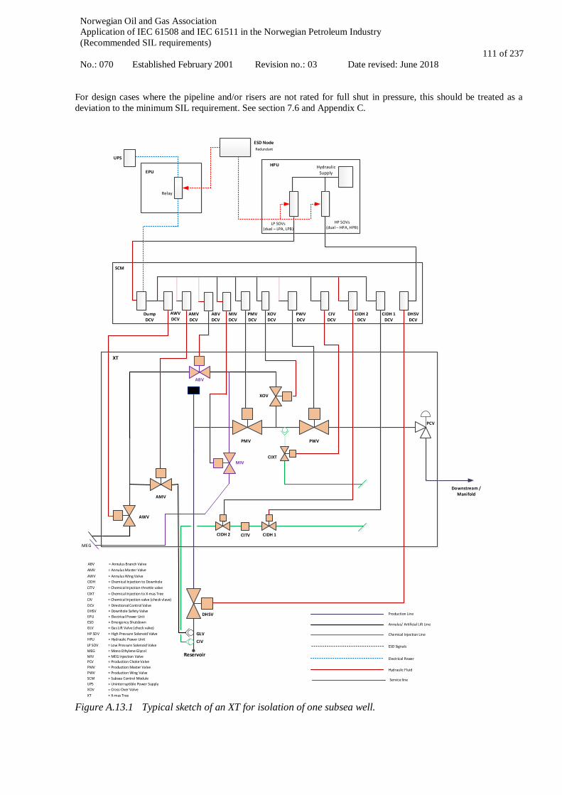
Norwegian Oil and Gas Association Application of IEC 61508 and IEC 61511 in the Norwegian Petroleum Industry (Recommended SIL requirements) No.: 070 Established February 2001 Revision no.: 03 Date revised: June 2018
111 of 237
For design cases where the pipeline and/or risers are not rated for full shut in pressure, this should be treated as a deviation to the minimum SIL requirement. See section 7.6 and Appendix C.
Downstream /Manifold
Reservoir
PMV
AMV
AWV
PWV
XOV
CIXT
CIDH 1
DHSV
CIDH 2
SCM
DumpDCV
AWVDCV
AMVDCV
PMVDCV
XOVDCV
PWVDCV
CIVDCV
CIDH 1DCV
CIDH 2DCV
DHSVDCV
EPUHPU
UPS
Hydraulic Supply
ESD Node
Relay
PCV
XT
AMV = Annulus Master ValveAWV = Annulus Wing ValveCIDH = Chemical Injection to Downhole
DCV = Directional Control ValveDHSV = Downhole Safety ValveEPU = Electrical Power UnitESD = Emergency Shutdown
HPU = Hydraulic Power Unit
PCV = Production Choke ValvePMV = Production Master ValvePWV = Production Wing ValveSCM = Subsea Control ModuleUPS = Uninterruptible Power Supply
Production Line
Annulus/ Artificial Lift Line
Chemical Injection Line
ESD Signals
Electrical Power
Hydraulic Fluid
LP SOVs(dual – LPA, LPB)
HP SOVs(dual – HPA, HPB)
XOV = Cross-Over ValveXT = X-mas Tree
LP SOV = Low Pressure Solenoid Valve
HP SOV = High Pressure Solenoid Valve
Redundant
ABV
ABVDCV
Service line
MIV
MIVDCV
MEG
CITV
GLV = Gas Lift Valve (check valve)
CIV = Chemical Injection valve (check vlave)CIXT = Chemical Injection to X-mas Tree
GLV
CIV
ABV = Annulus Branch Valve
CITV = Chemical Injection throttle valve
MEG = Mono Ethylene GlycolMIV = MEG Injection Valve
Figure A.13.1 Typical sketch of an XT for isolation of one subsea well.
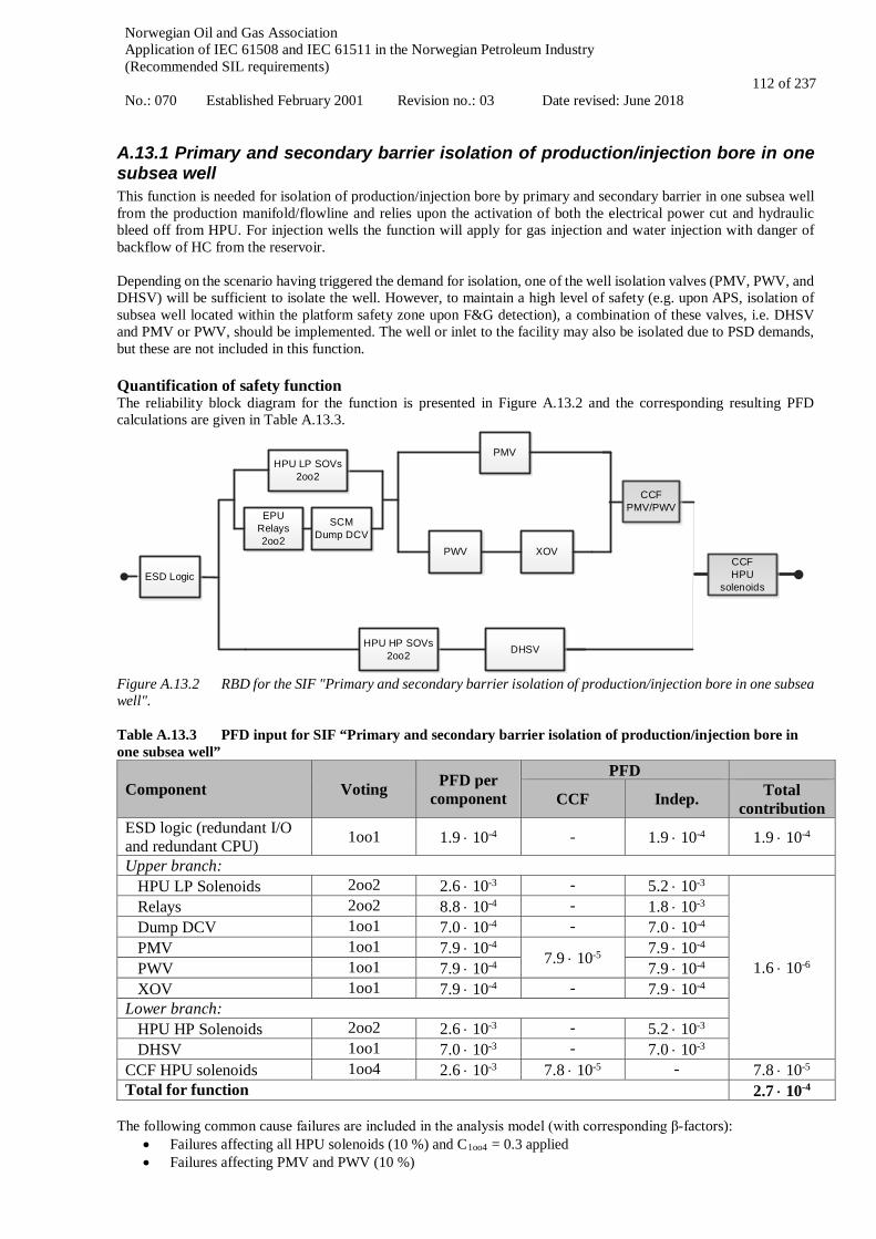
Norwegian Oil and Gas Association Application of IEC 61508 and IEC 61511 in the Norwegian Petroleum Industry (Recommended SIL requirements) No.: 070 Established February 2001 Revision no.: 03 Date revised: June 2018
112 of 237
A.13.1 Primary and secondary barrier isolation of production/injection bore in one subsea well This function is needed for isolation of production/injection bore by primary and secondary barrier in one subsea well from the production manifold/flowline and relies upon the activation of both the electrical power cut and hydraulic bleed off from HPU. For injection wells the function will apply for gas injection and water injection with danger of backflow of HC from the reservoir. Depending on the scenario having triggered the demand for isolation, one of the well isolation valves (PMV, PWV, and DHSV) will be sufficient to isolate the well. However, to maintain a high level of safety (e.g. upon APS, isolation of subsea well located within the platform safety zone upon F&G detection), a combination of these valves, i.e. DHSV and PMV or PWV, should be implemented. The well or inlet to the facility may also be isolated due to PSD demands, but these are not included in this function. Quantification of safety function The reliability block diagram for the function is presented in Figure A.13.2 and the corresponding resulting PFD calculations are given in Table A.13.3.
ESD Logic
HPU LP SOVs 2oo2
EPURelays2oo2
SCM Dump DCV
PWV XOV
PMV
DHSVHPU HP SOVs 2oo2
CCF PMV/PWV
CCF HPU
solenoids
Figure A.13.2 RBD for the SIF "Primary and secondary barrier isolation of production/injection bore in one subsea well". Table A.13.3 PFD input for SIF “Primary and secondary barrier isolation of production/injection bore in one subsea well”
Component Voting PFD per component
PFD
CCF Indep. Total contribution
ESD logic (redundant I/O and redundant CPU) 1oo1 1.9 ⋅ 10-4 - 1.9 ⋅ 10-4 1.9 ⋅ 10-4
Upper branch: HPU LP Solenoids 2oo2 2.6 ⋅ 10-3 - 5.2 ⋅ 10-3
1.6 ⋅ 10-6
Relays 2oo2 8.8 ⋅ 10-4 - 1.8 ⋅ 10-3 Dump DCV 1oo1 7.0 ⋅ 10-4 - 7.0 ⋅ 10-4 PMV 1oo1 7.9 ⋅ 10-4 7.9 ⋅ 10-5 7.9 ⋅ 10-4 PWV 1oo1 7.9 ⋅ 10-4 7.9 ⋅ 10-4 XOV 1oo1 7.9 ⋅ 10-4 - 7.9 ⋅ 10-4 Lower branch: HPU HP Solenoids 2oo2 2.6 ⋅ 10-3 - 5.2 ⋅ 10-3 DHSV 1oo1 7.0 ⋅ 10-3 - 7.0 ⋅ 10-3 CCF HPU solenoids 1oo4 2.6 ⋅ 10-3 7.8 ⋅ 10-5 - 7.8 ⋅ 10-5 Total for function 2.7 ⋅ 10-4
The following common cause failures are included in the analysis model (with corresponding β-factors):
• Failures affecting all HPU solenoids (10 %) and C1oo4 = 0.3 applied • Failures affecting PMV and PWV (10 %)

Norwegian Oil and Gas Association Application of IEC 61508 and IEC 61511 in the Norwegian Petroleum Industry (Recommended SIL requirements) No.: 070 Established February 2001 Revision no.: 03 Date revised: June 2018
113 of 237
The result indicates that this function for primary and secondary barrier isolation of production/injection bore fulfils a SIL 3 requirement. This function for primary and secondary barrier isolation of production/injection bore may be implemented with two independent sub-functions:
- Primary barrier isolation (DHSV) of production/injection bore in one subsea well, SIL1 - Secondary barrier isolation (PMV/PWV) of production/injection bore in one subsea well, SIL2
SIL3 compliance for the overall primary and secondary barrier isolation (combining the two functions above) shall be demonstrated. The details for the two independent sub-functions are described below. A.13.1.1 Secondary barrier isolation of production/injection bore in one subsea well As described in at the beginning of A.13, some causes may require the isolation of secondary well barrier only. When this function is activated one of the XT isolation valves (PMV, PWV) will be sufficient to isolate the well. The well or inlet to the facility may also be isolated due to PSD demands, but these are not included in this sub-function. The secondary barrier isolation of production/injection bore in one subsea well may be realized by activation of electrical power cut only. Activation is typically triggered upon fire and gas detection in riser area (for wells located away from platform safety zone). Bleed off of low pressure hydraulic from HPU has not been included as this action is generally not required as part of a secondary/single barrier isolation logic. Bleed-off of low pressure hydraulic from HPU may however be applied as an alternative (or in addition) to the power cut if the response time can be verified to be within the process safety time. The reliability block diagram for the sub-function is presented in Figure A.13.3 and the corresponding resulting PFD calculations are given in Table A.13.4.
ESD Logic EPU Relays2oo2
SCM Dump DCV
PMV
PWV XOV
CCF PMV/PWV
Figure A.13.3 RBD for the SIF "Secondary barrier isolation of production bore in one subsea well". Table A.13.4 PFD input for SIF “Secondary barrier isolation of production bore in one subsea well”
Component Voting PFD per component
PFD CCF Indep. Total
contribution ESD logic (redundant I/O and redundant CPU) 1oo1 1.9 · 10-4 - - 1.9 · 10-4
Relays 2oo2 8.8 · 10-4 - - 1.8 · 10-3 Dump DCV 1oo1 7.0 · 10-4 - - 7.0 · 10-4 PMV 1oo1 7.9 · 10-4
- 7.9 · 10-4
1.7 · 10-6 PWV 1oo1 7.9 · 10-4 7.9 · 10-4 XOV 1oo1 7.9 · 10-4 - 7.9 · 10-4 CCF PMV/PWV 1oo2 7.9 · 10-4 7.9 · 10-5 - 7.9 · 10-5 Total for sub-function 3.4 · 10-3
The following common cause failures are included in the analysis model (with corresponding β-factors):
• Failures affecting PMV and PWV (10 %)
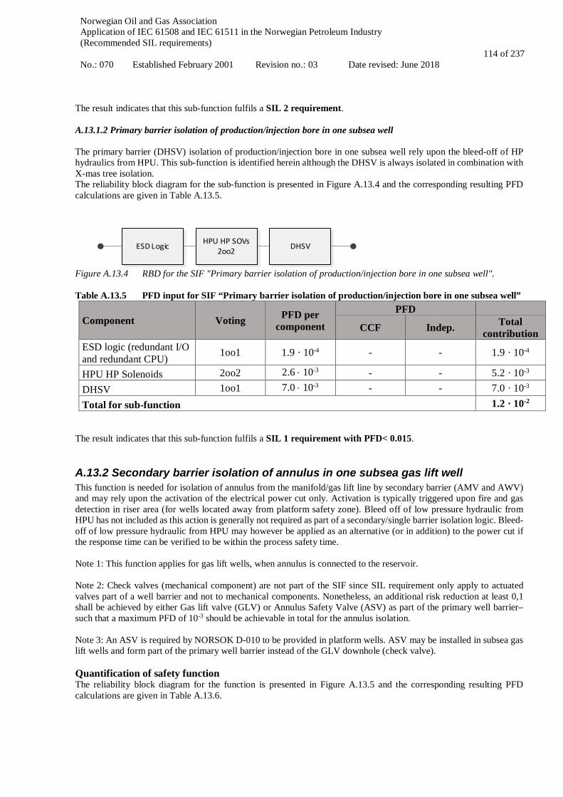
Norwegian Oil and Gas Association Application of IEC 61508 and IEC 61511 in the Norwegian Petroleum Industry (Recommended SIL requirements) No.: 070 Established February 2001 Revision no.: 03 Date revised: June 2018
114 of 237
The result indicates that this sub-function fulfils a SIL 2 requirement. A.13.1.2 Primary barrier isolation of production/injection bore in one subsea well The primary barrier (DHSV) isolation of production/injection bore in one subsea well rely upon the bleed-off of HP hydraulics from HPU. This sub-function is identified herein although the DHSV is always isolated in combination with X-mas tree isolation. The reliability block diagram for the sub-function is presented in Figure A.13.4 and the corresponding resulting PFD calculations are given in Table A.13.5.
ESD Logic HPU HP SOVs 2oo2 DHSV
Figure A.13.4 RBD for the SIF "Primary barrier isolation of production/injection bore in one subsea well". Table A.13.5 PFD input for SIF “Primary barrier isolation of production/injection bore in one subsea well”
Component Voting PFD per component
PFD CCF Indep. Total
contribution ESD logic (redundant I/O and redundant CPU) 1oo1 1.9 · 10-4 - - 1.9 · 10-4
HPU HP Solenoids 2oo2 2.6 ⋅ 10-3 - - 5.2 · 10-3 DHSV 1oo1 7.0 ⋅ 10-3 - - 7.0 · 10-3 Total for sub-function 1.2 · 10-2
The result indicates that this sub-function fulfils a SIL 1 requirement with PFD< 0.015.
A.13.2 Secondary barrier isolation of annulus in one subsea gas lift well This function is needed for isolation of annulus from the manifold/gas lift line by secondary barrier (AMV and AWV) and may rely upon the activation of the electrical power cut only. Activation is typically triggered upon fire and gas detection in riser area (for wells located away from platform safety zone). Bleed off of low pressure hydraulic from HPU has not included as this action is generally not required as part of a secondary/single barrier isolation logic. Bleed-off of low pressure hydraulic from HPU may however be applied as an alternative (or in addition) to the power cut if the response time can be verified to be within the process safety time. Note 1: This function applies for gas lift wells, when annulus is connected to the reservoir. Note 2: Check valves (mechanical component) are not part of the SIF since SIL requirement only apply to actuated valves part of a well barrier and not to mechanical components. Nonetheless, an additional risk reduction at least 0,1 shall be achieved by either Gas lift valve (GLV) or Annulus Safety Valve (ASV) as part of the primary well barrier– such that a maximum PFD of 10-3 should be achievable in total for the annulus isolation. Note 3: An ASV is required by NORSOK D-010 to be provided in platform wells. ASV may be installed in subsea gas lift wells and form part of the primary well barrier instead of the GLV downhole (check valve). Quantification of safety function The reliability block diagram for the function is presented in Figure A.13.5 and the corresponding resulting PFD calculations are given in Table A.13.6.

Norwegian Oil and Gas Association Application of IEC 61508 and IEC 61511 in the Norwegian Petroleum Industry (Recommended SIL requirements) No.: 070 Established February 2001 Revision no.: 03 Date revised: June 2018
115 of 237
ESD Logic EPU Relays2oo2
SCM Dump DCV
AMV
AWV
CCF PMV/PWV
Figure A.13.5 RBD for the SIF "Secondary barrier isolation of annulus in one subsea gas lift well". Table A.13.6 PFD input for SIF “Secondary barrier isolation of annulus in one subsea gas lift well”
Component Voting PFD per component
PFD CCF Indep. Total
contribution ESD logic (redundant I/O and redundant CPU) 1oo1 1.9 · 10-4 - - 1.9 · 10-4
Relays 2oo2 8.8 · 10-4 - - 1.8 · 10-3 Dump DCV 1oo1 7.0 · 10-4 - - 7.0 · 10-4 AMV 1oo1 7.9 · 10-4
- 7.9 · 10-4
8.3 · 10-7 AWV 1oo1 7.9 · 10-4 7.9 · 10-4 CCF AMV/AWV 1oo2 7.9 · 10-4 7.9 · 10-5 - 7.9 · 10-5 Total for function 3.4 · 10-3
The following common cause failures are included in the analysis model (with corresponding β-factors):
• Failures affecting AMV and AWV (10 %) The result indicates that this function fulfils a SIL 2 requirement.
A.13.3 Secondary barrier isolation of one chemical injection line in one subsea well This is the function needed for secondary barrier isolation of one chemical injection line from reservoir backflow:
• Isolation of one chemical injection line with CIXT valve connected between Production master valve (PMV) and Production wing valve (PWV) from reservoir backflow, e.g. MEG, corrosion / scale inhibitor, or
• Isolation of one downhole chemical injection line from reservoir backflow with CIDH valve. These functions may rely upon the activation of the electrical power cut only. Activation is typically triggered upon fire and gas detection in riser area (for wells located away from platform safety zone). Bleed off of low pressure hydraulic from HPU has not been included as this action is generally not required as part of a secondary/single barrier isolation logic. Bleed-off of low pressure hydraulic from HPU may however be applied as an alternative (or in addition) to the power cut if the response time can be verified to be within the process safety time. Note 1: 1. The chemical injection lines connected to the XT are also protected from reservoir back flow by a check valve, the
production master valve (PMV), and the downhole safety valve (DHSV). Only the CIXT has been included in the boundary of the function for simplification purpose.
2. Downhole chemical injection line is required to be protected from reservoir back flow by a downhole chemical injection check valve (CIV) in addition to the CIDH. SIL requirement apply to actuated valves and not to check valves (mechanical component). The CIV should therefore not be considered as being part of a SIF (not subject to SIL requirement) but it is expected to provide an additional (independent) risk reduction of at least 0,1.
These two functions are similar and the RBD and PFD calculations are the same, i.e. the SIF typical is applicable to chemical injection lines connected both downhole or to the XT. Note 2: Single chemical injection valves (CIXT/CIDH) has been assumed in the RBD. In Figure A.32 redundant CIDH is shown, however the second valve has been installed to be able to leak test the first CIXT/CIDH – but it typically cannot be leak tested itself due to large volume in umbilical. ISO 13628-4 allows single fail-safe isolation with a check valve for lines smaller than 1 inch. Quantification of safety function

Norwegian Oil and Gas Association Application of IEC 61508 and IEC 61511 in the Norwegian Petroleum Industry (Recommended SIL requirements) No.: 070 Established February 2001 Revision no.: 03 Date revised: June 2018
116 of 237
The reliability block diagram for the function is presented in Figure A.13.6 and the corresponding resulting PFD calculations are given in Table A.13.7.
ESD Logic EPU Relays2oo2
SCM Dump DCV CIXT/CIDH
Figure A.13.6 RBD for the SIF "Secondary barrier isolation of one line of chemical injection in one subsea well". Table A.13.7 PFD input for SIF “Secondary barrier solation of one chemical injection line in one subsea well”
Component Voting PFD per component
PFD CCF Indep.
ESD logic (redundant I/O and redundant CPU) 1oo1 1.9 ⋅ 10-4 - 1.9 ⋅ 10-4
Relays 2oo2 8.8 ⋅ 10-4 - 1.8 ⋅ 10-3 Dump DCV 1oo1 7.0 ⋅ 10-4 - 7.0 ⋅ 10-4 CIXT/CIDH 1oo1 9.6 ⋅ 10-4 - 9.6 ⋅ 10-4 Total for function 3.7 ⋅ 10-3
The results indicate that this function achieves a PFD lower than 10-2 (within SIL2 range). However, considering industry generic data (PDS handbook) a maximum SIL 1 is achievable with a single isolation valve due to architectural constraints. Overall a SIL 1 requirement is specified for this function, supported by the following: • ISO 13628-4 allows for a single fail-safe isolation in combination with a check valve, for lines smaller than 1
inch • The risk associated with backflow is generally insignificant for this down-hole injection line due to:
o Potential for volume of hydrocarbons flowing back in DH chemical injection line is much less for a small bore line than for larger lines like the production line
o The DH chemical injection line is normally pressurized behind a closed isolation valve o When injecting, the injection pressure is normally higher than the flowing pressure o Long lines with small bore is likely to be plugged by hydrates should fluids from reservoir flow back
Note that testability of barriers should be considered in design, which may lead to additional isolation valves.
A.13.4 Secondary barrier isolation of one service line from one subsea well This is the sub-function needed for isolation of one service line in one subsea well from reservoir backflow and may rely upon the activation of the electrical power cut only. Activation is typically triggered upon fire and gas detection in riser area (for wells located away from platform safety zone). Bleed off of low pressure hydraulic from HPU has not been included as this action is generally not required as part of a secondary/single barrier isolation logic. Bleed-off of low pressure hydraulic from HPU may however be applied as an alternative (or in addition) to the power cut if the response time can be verified to be within the process safety time. The service line is normally a 2-inch line in the umbilical with various applications, incl. injection of MEG/methanol in XMT or pipes. The service line goes through the XOV (which has to be open to avoid accumulation of hydrate). The line is also used for pressure supply when opening the DHSV. Note: isolation of PMV and DHSV provide an additional protection against reservoir backflow but has not been included for the purpose of simplification. A maximum PFD of 10-3 should be achievable in total accounting for all these valves. Quantification of safety functions The reliability block diagram for this function is presented in Figure A.13.7. The PFD calculations are presented in Table A.13.8.
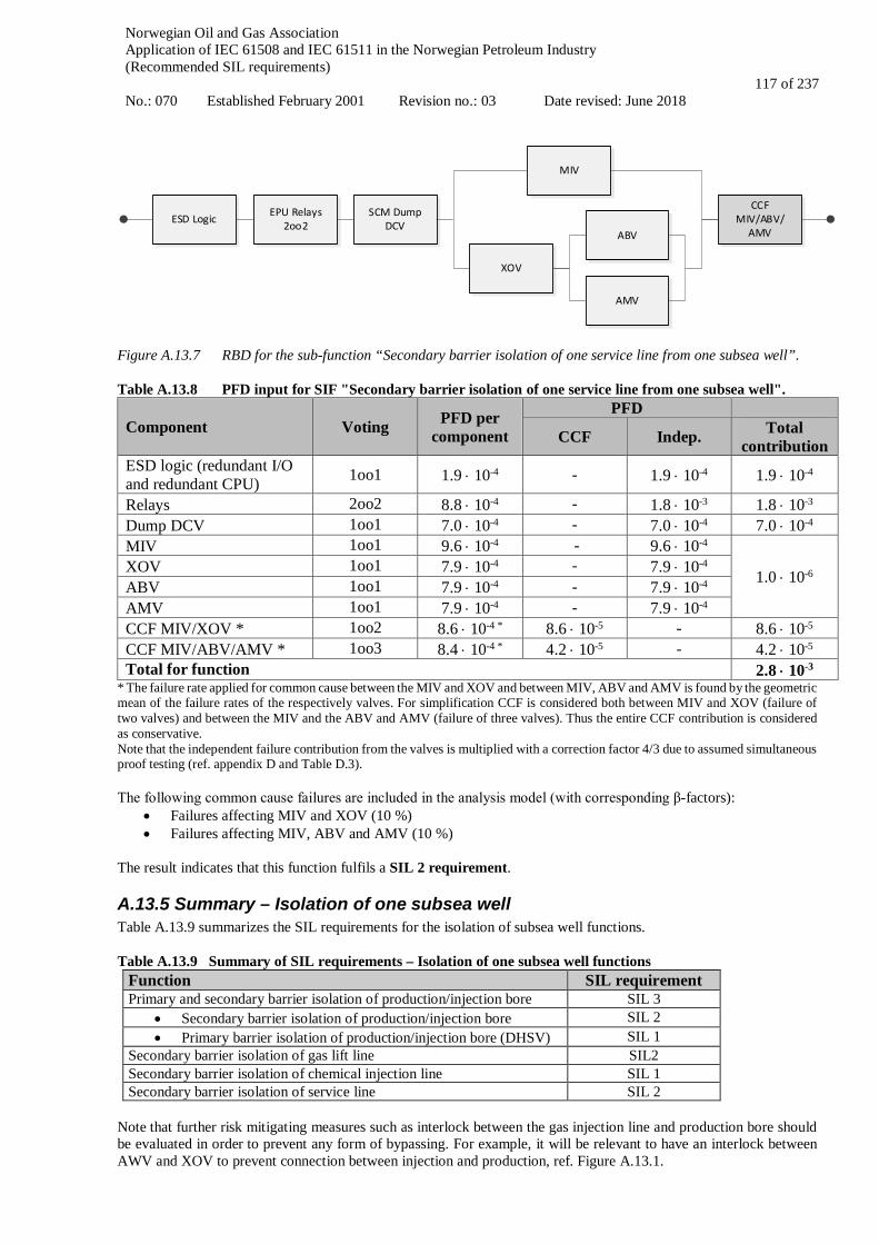
Norwegian Oil and Gas Association Application of IEC 61508 and IEC 61511 in the Norwegian Petroleum Industry (Recommended SIL requirements) No.: 070 Established February 2001 Revision no.: 03 Date revised: June 2018
117 of 237
Figure A.13.7 RBD for the sub-function “Secondary barrier isolation of one service line from one subsea well”. Table A.13.8 PFD input for SIF "Secondary barrier isolation of one service line from one subsea well".
Component Voting PFD per component
PFD
CCF Indep. Total contribution
ESD logic (redundant I/O and redundant CPU) 1oo1 1.9 ⋅ 10-4 - 1.9 ⋅ 10-4 1.9 ⋅ 10-4
Relays 2oo2 8.8 ⋅ 10-4 - 1.8 ⋅ 10-3 1.8 ⋅ 10-3 Dump DCV 1oo1 7.0 ⋅ 10-4 - 7.0 ⋅ 10-4 7.0 ⋅ 10-4 MIV 1oo1 9.6 ⋅ 10-4 - 9.6 ⋅ 10-4
1.0 ⋅ 10-6 XOV 1oo1 7.9 ⋅ 10-4 - 7.9 ⋅ 10-4 ABV 1oo1 7.9 ⋅ 10-4 - 7.9 ⋅ 10-4 AMV 1oo1 7.9 ⋅ 10-4 - 7.9 ⋅ 10-4 CCF MIV/XOV * 1oo2 8.6 ⋅ 10-4 * 8.6 ⋅ 10-5 - 8.6 ⋅ 10-5 CCF MIV/ABV/AMV * 1oo3 8.4 ⋅ 10-4 * 4.2 ⋅ 10-5 - 4.2 ⋅ 10-5 Total for function 2.8 ⋅ 10-3
* The failure rate applied for common cause between the MIV and XOV and between MIV, ABV and AMV is found by the geometric mean of the failure rates of the respectively valves. For simplification CCF is considered both between MIV and XOV (failure of two valves) and between the MIV and the ABV and AMV (failure of three valves). Thus the entire CCF contribution is considered as conservative. Note that the independent failure contribution from the valves is multiplied with a correction factor 4/3 due to assumed simultaneous proof testing (ref. appendix D and Table D.3). The following common cause failures are included in the analysis model (with corresponding β-factors):
• Failures affecting MIV and XOV (10 %) • Failures affecting MIV, ABV and AMV (10 %)
The result indicates that this function fulfils a SIL 2 requirement.
A.13.5 Summary – Isolation of one subsea well Table A.13.9 summarizes the SIL requirements for the isolation of subsea well functions. Table A.13.9 Summary of SIL requirements – Isolation of one subsea well functions
Function SIL requirement Primary and secondary barrier isolation of production/injection bore SIL 3
• Secondary barrier isolation of production/injection bore SIL 2 • Primary barrier isolation of production/injection bore (DHSV) SIL 1
Secondary barrier isolation of gas lift line SIL2 Secondary barrier isolation of chemical injection line SIL 1 Secondary barrier isolation of service line SIL 2
Note that further risk mitigating measures such as interlock between the gas injection line and production bore should be evaluated in order to prevent any form of bypassing. For example, it will be relevant to have an interlock between AWV and XOV to prevent connection between injection and production, ref. Figure A.13.1.
ESD Logic EPU Relays2oo2
SCM Dump DCV
MIV
XOV
CCF MIV/ABV/
AMVABV
AMV

Norwegian Oil and Gas Association Application of IEC 61508 and IEC 61511 in the Norwegian Petroleum Industry (Recommended SIL requirements) No.: 070 Established February 2001 Revision no.: 03 Date revised: June 2018
118 of 237
When designing the SIF using isolation of hydraulic power to shut subsea XT and DHSV valves it is necessary to carrying out hydraulic and electrical analysis to verify that the response time of the system design is adequate and meets the SRS. It should be noted that quick response times rely upon the electrical isolation and SCM dump valve. For subsea wells which are not directly exposing the receiving/adjacent facility, long response time of the hydraulic bleed off from topside/shore is normally acceptable provided all XT valves are electrically fail-safe and close quickly (i.e. the response time is shorter than the process safety time). The inventory in the production flowline will generally be large and in case of failure of the power-cut / closure of XT valves, the increased produced inventory until isolation of DHSV by hydraulic bleed-off may not significantly change the risk. The above supports that well control system designs which rely on electric power cut only (and not on hydraulic bleed off from shore/topside due to long distance and very long bleed-off time) may be found acceptable. In those cases, minimum PFD requirement in the range of SIL2 – SIL 3 may apply for isolation of production/injection bore by primary and secondary barrier. A quantitative risk analysis should be conducted to verify that the minimum SIL-requirement gives an acceptable risk when the total number of wells is taken into consideration. The following should be considered:
• Number of wells; • Production / injection wells with or without gas-lift; • Wells in connection with workover / well intervention operations, such as wire line, coiled tubing, testing, etc.; • Potential common cause failures between valves.

Norwegian Oil and Gas Association Application of IEC 61508 and IEC 61511 in the Norwegian Petroleum Industry (Recommended SIL requirements) No.: 070 Established February 2001 Revision no.: 03 Date revised: June 2018
119 of 237
A.14 Drilling Well barriers used during drilling are described in NORSOK D-001 Drilling facilities and NORSOK D-010 Well integrity in drilling and well operations. The drilling BOP should be constructed in accordance with NORSOK D-001, API 16A, API 16D and API 53. A drilling BOP is defined as part of a barrier, and therefore requires strategies and principles that form the basis for design, use and maintenance of barrier, so that the barrier will function as required. One function of the drilling BOP is to provide capabilities to close in and seal the well bore with or without tools/equipment through the BOP. This would be the shear seal ram, casing shear ram and auto safety functions for disconnect. Some BOP designs have internal ram locking mechanisms that are activated with the close function. For BOP designs where ram locking mechanisms are not part of closing the ram, SIL requirement for the separate mechanical ram locking should be given. Thus, the following drilling related safety instrumented functions are discussed in this appendix:
• Shear seal ram and casing shear ram function • Sequenced shutdown function (emergency disconnect, autoshear) • Mechanical ram lock function
Note that the above BOP functions are not independent of each other as they share common components. In sections A.14.1–A.14.3, each of the three functions are described separately, whereas dependencies between functions are briefly discussed in section 8.7. Note that if a well has a significantly high risk then stricter requirements than given here may need to be considered (see e.g. section 7.6 in this guideline). Functional boundaries of the BOP functions Each function typically starts when the operator (e.g. driller or tool pusher) presses the buttons to close the well (and to disconnect). This includes the activation and signal transfer system and the activation systems (incl. sub plate mounted (SPM) valves, pods, accumulators and return). The functions are here assumed to end at safe state, as defined for the actual functions, implying shearing and/or sealing off the well in order to prevent flow of hydrocarbons out of the wellbore. The subsequent steps needed to normalize the well is not assumed as part of the functions with SIL requirements. Activation of the BOP functions There are various methods available for activation of BOP functions, both manual and automatic, depending on the type of facility and if it is a surface BOP or a subsea BOP:
• Electrical or fibre optical control signal from surface and/or conventional direct hydraulic control signals. • Acoustic control signal from the surface. • Deadman after loss of electrical and hydraulic power to pod (failed control lines). • Autoshear triggered by mechanical device if LMRP is separated from lower BOP. • Automatic disconnect system (ADS) closes the shear seal rams and disconnects when the lower flex joint
reaches a pre-set angle. All manually activated functions can be activated from the driller's panel or the tool pusher panel. The sequenced function may additionally be activated by a trigger system. Acoustic release (by means of lowering transceivers and triggering a release from the well through acoustic signal to the pods) is required for operations on the Norwegian Continental Shelf. However, acoustic initiation only serves as a back-up in case normal control has failed. No SIL requirement has been allocated to the acoustic back-up function. Testing requirements for the BOP functions The BOP includes instrumented functions for normal operation as well as safety functions. The safety functions have a lower demand than the normal operation functions. Proof testing is therefore strictly required to reveal failures and ensure performance, ref. section 10.5 of this guideline. Testing of the drilling BOP is outlined in NORSOK D-010 (Appendix A, Table A.1): Proof test of shear seal ram functions should be performed weekly, with activation from alternating panels/pods and/or by acoustic activation. With alternating activation of the pods this means that the actual activation function is fully tested every second week.

Norwegian Oil and Gas Association Application of IEC 61508 and IEC 61511 in the Norwegian Petroleum Industry (Recommended SIL requirements) No.: 070 Established February 2001 Revision no.: 03 Date revised: June 2018
120 of 237
Shear seal ram functions, ram lock functions, shear boost and sequenced functions for disconnect, deadman and autoshear shall in addition be function tested "on stump", i.e. between wells / prior to operation of well. Pressure testing of shear seal rams should be performed every second week to maximum section design pressure (MSDP) and every 6th month to working pressure. Furthermore, it is required that the BOP with associated valves with control system and other pressure control equipment shall be subject to overhaul/recertification every five years, ref. PSA Activity Regulation §51. According to the above requirements, the BOP components have a proof test interval ranging from weekly to 6 monthly. The most critical components, i.e. the shear seal ram and the casing shear ram, are proof tested weekly and it is redundancy and/or compensating measures for most of the others. Therefore a proof test interval of two weeks seems an appropriate assumption. RBDs for the BOP functions Figures A.14.1 and A.14.2 shows the RBD's for a subsea BOP and surface BOP respectively, comprising the following safety functions:
• Close shear seal ram • Activate mechanical ram lock if there is a separate function and not part of the shear seal ram as illustrated in
figures A.14.1 and A.14.2.
Pushbutton Pushbutton Logic Solver Pilot valveRam Close
Pilot operated manipulator valve (directional valve)
Ram Close
Pilot operated manipulator valve (directional valve)
Pilot valve
SUBSEA BOP
Ram/Mechanical Ram lock
Umbilical(s)(direct hydraulic/pod supply/MUX/
rigid condiut)
Accumulator(s):Ram close/ assist
Shear boostAcoustic
Conduit manifold- SPMs, POCV, regulators, filter,
relief valves
Pod B- SPMs, SEM, solenoids &
batteries
Pilot operated manipulator valve(directional valve)
Pod Select
Pilot valvesYellow / Blue
HP pod supply
Pod A- SPM’s, SEM, solenoids &
batteries
Only relevant for some system
configurations
Only DD failures, included for illustration
SEM – Subsea Electronic ModulesPOCV – Pilot Operated Check ValveSPM – Sub Plate Mounted valve
Figure A.14.1 Generic RBD for subsea BOP comprising shear seal ram function and mechanical lock function.
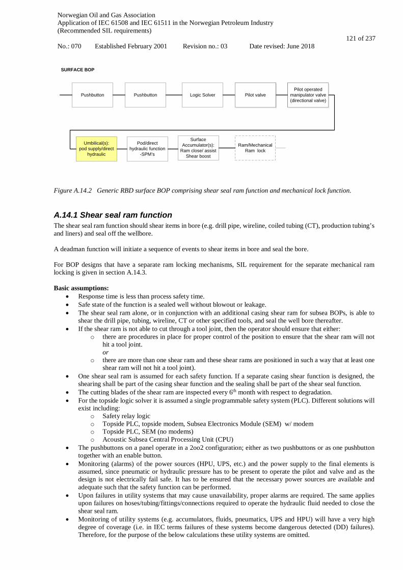
Norwegian Oil and Gas Association Application of IEC 61508 and IEC 61511 in the Norwegian Petroleum Industry (Recommended SIL requirements) No.: 070 Established February 2001 Revision no.: 03 Date revised: June 2018
121 of 237
Ram/Mechanical Ram lock
Pushbutton Pushbutton Logic Solver Pilot valveRam Close
Pilot operated manipulator valve (directional valve)
Ram Close
Umbilical(s):pod supply/direct
hydraulic
Surface Accumulator(s):
Ram close/ assistShear boost
Pilot operated manipulator valve (directional valve)
Pilot valve
Pod/direct hydraulic function
-SPM’s
SURFACE BOP
Figure A.14.2 Generic RBD surface BOP comprising shear seal ram function and mechanical lock function.
A.14.1 Shear seal ram function The shear seal ram function should shear items in bore (e.g. drill pipe, wireline, coiled tubing (CT), production tubing’s and liners) and seal off the wellbore. A deadman function will initiate a sequence of events to shear items in bore and seal the bore. For BOP designs that have a separate ram locking mechanisms, SIL requirement for the separate mechanical ram locking is given in section A.14.3. Basic assumptions:
• Response time is less than process safety time. • Safe state of the function is a sealed well without blowout or leakage. • The shear seal ram alone, or in conjunction with an additional casing shear ram for subsea BOPs, is able to
shear the drill pipe, tubing, wireline, CT or other specified tools, and seal the well bore thereafter. • If the shear ram is not able to cut through a tool joint, then the operator should ensure that either:
o there are procedures in place for proper control of the position to ensure that the shear ram will not hit a tool joint. or
o there are more than one shear ram and these shear rams are positioned in such a way that at least one shear ram will not hit a tool joint).
• One shear seal ram is assumed for each safety function. If a separate casing shear function is designed, the shearing shall be part of the casing shear function and the sealing shall be part of the shear seal function.
• The cutting blades of the shear ram are inspected every 6th month with respect to degradation. • For the topside logic solver it is assumed a single programmable safety system (PLC). Different solutions will
exist including: o Safety relay logic o Topside PLC, topside modem, Subsea Electronics Module (SEM) w/ modem o Topside PLC, SEM (no modems) o Acoustic Subsea Central Processing Unit (CPU)
• The pushbuttons on a panel operate in a 2oo2 configuration; either as two pushbuttons or as one pushbutton together with an enable button.
• Monitoring (alarms) of the power sources (HPU, UPS, etc.) and the power supply to the final elements is assumed, since pneumatic or hydraulic pressure has to be present to operate the pilot and valve and as the design is not electrically fail safe. It has to be ensured that the necessary power sources are available and adequate such that the safety function can be performed.
• Upon failures in utility systems that may cause unavailability, proper alarms are required. The same applies upon failures on hoses/tubing/fittings/connections required to operate the hydraulic fluid needed to close the shear seal ram.
• Monitoring of utility systems (e.g. accumulators, fluids, pneumatics, UPS and HPU) will have a very high degree of coverage (i.e. in IEC terms failures of these systems become dangerous detected (DD) failures). Therefore, for the purpose of the below calculations these utility systems are omitted.

Norwegian Oil and Gas Association Application of IEC 61508 and IEC 61511 in the Norwegian Petroleum Industry (Recommended SIL requirements) No.: 070 Established February 2001 Revision no.: 03 Date revised: June 2018
122 of 237
• Proof test interval of all equipment is 14 days, i.e. 336 hours (ref. above section on 'Testing requirements for the BOP functions').
Quantification of safety function The quantification of the shear seal ram function is presented in Table A.14.1. Table A.14.1 PFD input for safety function “shear seal ram” / "casing shear ram"
Component Voting PFD per component Total PFD
Pushbutton 2oo2 5.0 ⋅ 10-5 1.0 ⋅ 10-4 Single programmable safety system 1oo1 3.5 ⋅ 10-3 3.5 ⋅ 10-3 Control system (incl. pilot valves, DCV, HP pod supply, pods, shuttle valves, etc.)
1oo1 8.4 ⋅ 10-4 8.4 ⋅ 10-4
Shear seal ram (incl. ram lock) 1oo1 7.7 ⋅ 10-4 7.7 ⋅ 10-4 Total for function 5.2 ⋅ 10-3
The results indicate that a SIL 2 requirement is achievable for both the "shear seal ram" function and the “casing shear ram” function. Note that the casing shear ram is able to shear everything in the bore, without any sealing or locking requirements.
A.14.2 Sequenced shutdown functions (emergency disconnect, autoshear) Disconnection is required to prevent damage to the wellhead and barriers in the event that the drilling rig moves off location which can lead to damage to environment or loss of lives on the rig. A deadman function will isolate the well but not initiate disconnect of the rig from the well. Definition of boundaries The emergency disconnect function will initiate a sequence of events to shear items in bore, seal the bore and disconnect/unlatch from the well. The programmed sequence is often controlled from software in PLC in the BOP control system, including subsea electronics in pods. The emergency disconnect function is initiated from pushbutton or triggered automatically by the DP system. ADS and safe disconnect system (SDS) are initiated by mechanical trigger activated by pre-set angle of flex joint. Basic Assumptions (In addition to the shear seal ram assumptions in section A.14.1):
• Response time is less than process safety time. • Safe state of the emergency disconnect function is sealed wellbore and disconnected LMRP. • Disconnect is not dependent on successful sealing of the well, but delayed by a timer to give the preferred
sequence.
Quantification of safety function Figure A.14.3 provides a generic RBD schematic for the “sequenced shutdown functions”. The figure shall be valid for any of the functions:
• Emergency disconnect function initiated from pushbutton or triggered by DP system. • SDS/ADS initiated by mechanical trigger system activated by pre-set angle of flex joint. • Autoshear triggered by a mechanical device (located between LMRP and lower BOP) when LMRP is
separated from lower BOP. • Deadman function initiated by pods after loss of electrical and hydraulic power to both pods.
The PFD quantification is given in Table A.14.2.

Norwegian Oil and Gas Association Application of IEC 61508 and IEC 61511 in the Norwegian Petroleum Industry (Recommended SIL requirements) No.: 070 Established February 2001 Revision no.: 03 Date revised: June 2018
123 of 237
Pushbutton Pushbutton Logic Solver Umbilical(s)(pod supply/MUX)
Subsea Accumulator
system:Shear/close assist
AcousticConduit manifold- SPMs, POCV, regulators, filter,
relief valves
Pod B- SPMs, SEM, solenoids &
batteries
Pod A- SPMs, SEM, solenoids &
batteries
Autoshear valve module/
Acoustic solenoids,
SPMs, sensors and batteries, Acoustic logic
solver
Riser Connector
Shear sel ram / Casing shear ram
& mechanical lockingClose Secondary unlatch
-SPM´s, POCV´s
Primary unlatch -SPM´s, POCV´s
Choke & Kill valves close
Mini connectors/Stingers de-
energize & retract
Trigger system
Only relevant for some system
configurations
Only DD failures, included for illustration
Function activated, but not part of SIL
loop
PLC – Programmable Logic ControllerSEM – Subsea Electronic ModulesCPU – Central Processing UnitPOCV – Pilot Operated Check ValveSPM – Sub Plate Mounted valveEDS – Emergency Disconnect Sequence ADS – Automatic Disconnect Sequence
Figure A.14.3 RBD for sequenced shutdown functions (disconnect, autoshear). The sequenced shutdown function is similar to the shear seal ram function except from the unlatch part. Thus, the quantification is comparable and the SIL requirement equivalent. The quantification of the disconnect function is presented in Table A.14.2. Table A.14.2 PFD input for safety function “Sequenced shutdown system” (Emergency disconnect)
Component Voting PFD per component PFD CCF Indep.
Pushbutton 2oo2 5.0 ⋅ 10-5 - 1.0 ⋅ 10-4 Single programmable safety system 1oo1 3.5 ⋅ 10-3 3.5 ⋅ 10-3 Control system (incl. pilot valves, DCV, HP pod supply, pods, shuttle valves, etc.) 1oo1 8.4 ⋅ 10-4 - 8.4 ⋅ 10-4
Shear seal ram (incl. lock) 1oo1 7.7 ⋅ 10-4 - 7.7 ⋅ 10-4 Riser connector (incl. primary/secondary unlatch) 1oo1 4.0 ⋅ 10-3 - 4.0 ⋅ 10-3 Total for function 9.2 ⋅ 10-3
The results indicate that a SIL 2 requirement is achievable for the BOP function "sequenced shutdown function". The beta factor between the primary and secondary unlatch has been assumed to be 10 %. Notes regarding sequenced disconnect functions The purpose of this section is to address the definition of safe state for the emergency disconnect and provide an interpretation of how to implement the safety function in practice. As the safe state is disconnect, automatic disconnection should ideally occur upon loss of power or signal or detection of a dangerous fault (e.g. triggered by DP system), but this is not the case. Since the function is implemented using

Norwegian Oil and Gas Association Application of IEC 61508 and IEC 61511 in the Norwegian Petroleum Industry (Recommended SIL requirements) No.: 070 Established February 2001 Revision no.: 03 Date revised: June 2018
124 of 237
energize to activate and does not fail to a safe state, any loss of power, signal or hydraulic pressure should be detected and ensured by other supplies. Concerning the disconnect function, the proposed interpretation of the IEC 61511-1 failure classification framework is that any detected dangerous failure shall only trigger an alarm. Such failure would include loss of umbilical, PLC fault, loss of power, etc. This alarm shall start a human intervention process to either "repair" the function or initiate disconnection. The time required for this human intervention shall be shorter than the maximum allowable MTTR for the function. Hence, the function's behaviour upon detection of a fault is to trigger an alarm instead of disconnecting. The disconnect function is assumed implemented as follows:
• Upon loss of power, signal or hydraulic pressure, an alarm is triggered at the control panel. • Continuous monitoring of power and signal between topside and subsea. • Monitoring of accumulator pressure (working pressure). • Upon loss of one channel a predefined MTTR is applied. E.g. the rig operator takes steps to restore the faulty
channel or perform disconnect within the maximum allowed MTTR.
A.14.3 Mechanical ram lock function Mechanical locking is necessary to ensure shear seal rams remains closed. The function is added because there is still BOP operations where locking is a separate function initiated from a separate pushbutton. For BOPs with separate mechanical ram lock, a SIL 2 requirement is recommended.
A.14.4 Documentation of performance for BOP functions
This section describes a methodology intended for BOPs that are in service. In particular, the following references to other parts of this guideline is of huge relevance and should be well-known when using the method:
• Section 5.3.2 SIS follow-up during operation • Section 7.4 Definition of safety instrumented functions and SIL allocation • Section 7.6 Handling of deviations from the minimum SIL requirements • Appendix F which gives general information concerning follow-up of SIS in operation
For design of new functions, see chapter 8 on SIS design and engineering. For facilities in operation, the performance (PFD as for SIL 2) of the safety function can be documented based on results from proof tests as follows:
• Have a short document based on electric/hydraulic/mechanical documentation, giving a brief description of all components involved in the function. It should also show how the different components are functionally connected.
• A maintenance system where all the above components are identified shall be in place that collects reports from the proof tests (or other possible activations) on a component level.
• Failure of a component during proof test or operation should be registered with the correct identification and failure mode in the maintenance system.
• If the last 100 tests of the function have been successfully performed with one or no failures the function fulfils a PFD < 0.01. See appendix F for details.
• If redundancy is credited (like yellow/blue pod) it should be ensured that all redundant paths are tested individually to avoid hidden dangerous failures.
• The proof testing should be performed on the function "as is" prior to testing, i.e. before performing any repair (re-testing shall not be registered as a passed proof test).
• All components in the function should be proof tested under conditions as during a real demand. The shear seal ram boost/high function shall involve correct pressure to fully test the complete function of all components involved, including hydraulic lines representing a delayed/timed function.

Norwegian Oil and Gas Association Application of IEC 61508 and IEC 61511 in the Norwegian Petroleum Industry (Recommended SIL requirements) No.: 070 Established February 2001 Revision no.: 03 Date revised: June 2018
125 of 237
A.15 Well workover Well barriers used during well workover/intervention are as for drilling thoroughly described in NORSOK D-010 Well integrity in drilling and well operations.. During workover, there are other barriers than during drilling. In general, during workover operations, e.g. coiled tubing or wireline operations, the primary barrier starts with the tubing and ends with the stuffing box on top of the lubricator. For wireline operations, note that if the hydraulic master valve on the surface tree complies with NORSOK D-002 “Safety Head”, the HMV can be used as secondary barrier (with cutting abilities). This guideline presents relevant SIFs for the following workover set-ups/operations:
• Subsea workover; o Open water workover (tree mode) o In-riser workover (often called landing string workover or tubing hanger mode).
• Surface workover o Coiled tubing operation o Wireline operation o Snubbing operation
Basic assumptions A fully redundant programmable safety system topside is here assumed. Different solutions may exist, including:
• Topside PLC only • Topside PLC, topside modem, subsea electronics module w/ modem • Topside PLC, subsea electronics module (no modems)¨ • Topside relay logic
In the PFD quantifications for the functions presented here, topside PLC's only is assumed. In the present guideline a single configuration of the pushbutton is chosen. The operator only pushes one single pushbutton to initiate the shutdown sequence. A typical workover shutdown panel has three pushbuttons with protection cap to avoid spurious activation. The three buttons are PSD, ESD and EQD initiators. PSD is de-energize to safe state (normally energized) with single contact set, while ESD and EQD are energize to safe state with dual 1oo2 configured contact sets. The proof test interval is assumed to be 14 days, i.e. 336 hours, for the functions. Open water workover system Figure A.15.1 and Figure A.15.2 give a typical illustration of an open water (tree mode) workover system. A typical open water workover system comprises the following main components:
• Surface flow tree (SFT) o Surface production wing valve(s) o Master valve o Swab valve o Kill valve o Chemical injection valve
• Workover riser • Workover umbilical • Emergency disconnect package (EDP)
o Riser retainer valve o Side bore valves o EDP connector o Workover subsea control module
• Lower riser package (LRP) o Cutting and sealing main bore valves o Side bore valves
The SFT provides the interface to the process plant during a workover operation. The process plant is typically used for well testing after completion and for logging operations during production.

Norwegian Oil and Gas Association Application of IEC 61508 and IEC 61511 in the Norwegian Petroleum Industry (Recommended SIL requirements) No.: 070 Established February 2001 Revision no.: 03 Date revised: June 2018
126 of 237
The Workover riser is a high-pressure conduit from the well to the surface flow tree allowing direct access to the well through the EDP and the LRP. A single workover umbilical provides the hydraulic and electrical power required to control the functions in the EDP and LRP, often including power required for the workover system to override functions in the XMT, which allows the workover operator access to the well. The EDP provides the possibility for controlled and emergency disconnect of the workover riser system from the subsea well. In addition it contains retainer valves both for the main bore and for the side bore to prevent riser content from spilling to the sea upon disconnection. The subsea workover control module is located on the EDP. The LRP provides the workover analogy to a drilling BOP with cutting and sealing valves for emergency shutdown of the well. It also provides possibilities for chemical injections and circulation of fluids. The LRP is capable of sealing the well, both main bore and side bore (including annulus, chemical injection and crossover valves between production and annulus).
Figure A.15.1 Typical illustration of an open water (tree mode) workover system (ISO 13628-7:2005)
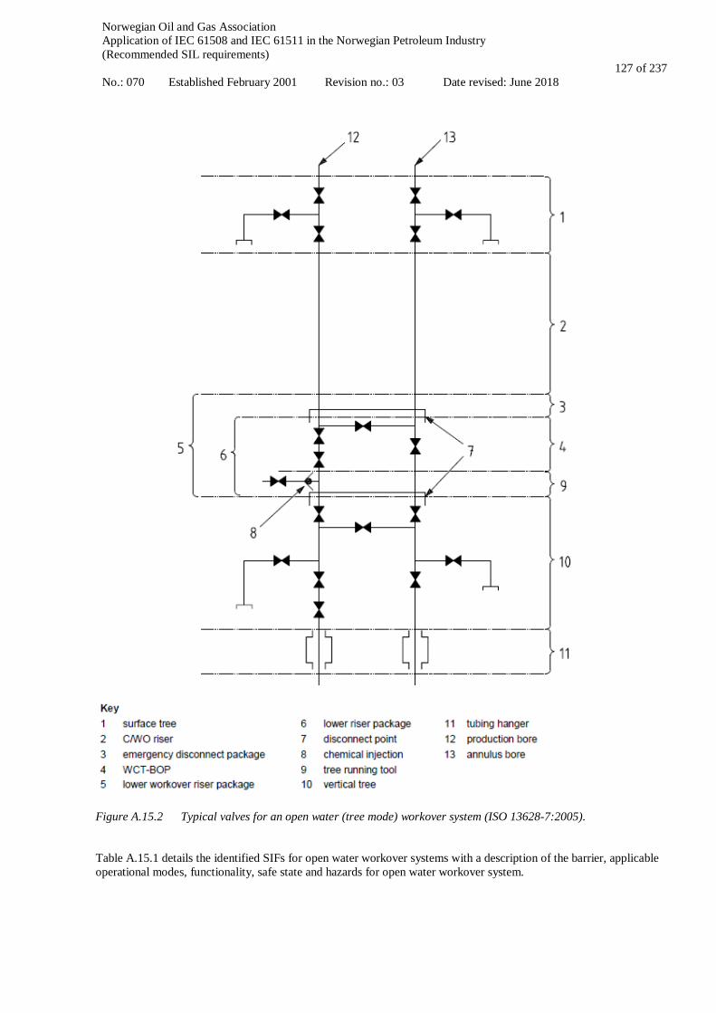
Norwegian Oil and Gas Association Application of IEC 61508 and IEC 61511 in the Norwegian Petroleum Industry (Recommended SIL requirements) No.: 070 Established February 2001 Revision no.: 03 Date revised: June 2018
127 of 237
Figure A.15.2 Typical valves for an open water (tree mode) workover system (ISO 13628-7:2005). Table A.15.1 details the identified SIFs for open water workover systems with a description of the barrier, applicable operational modes, functionality, safe state and hazards for open water workover system.
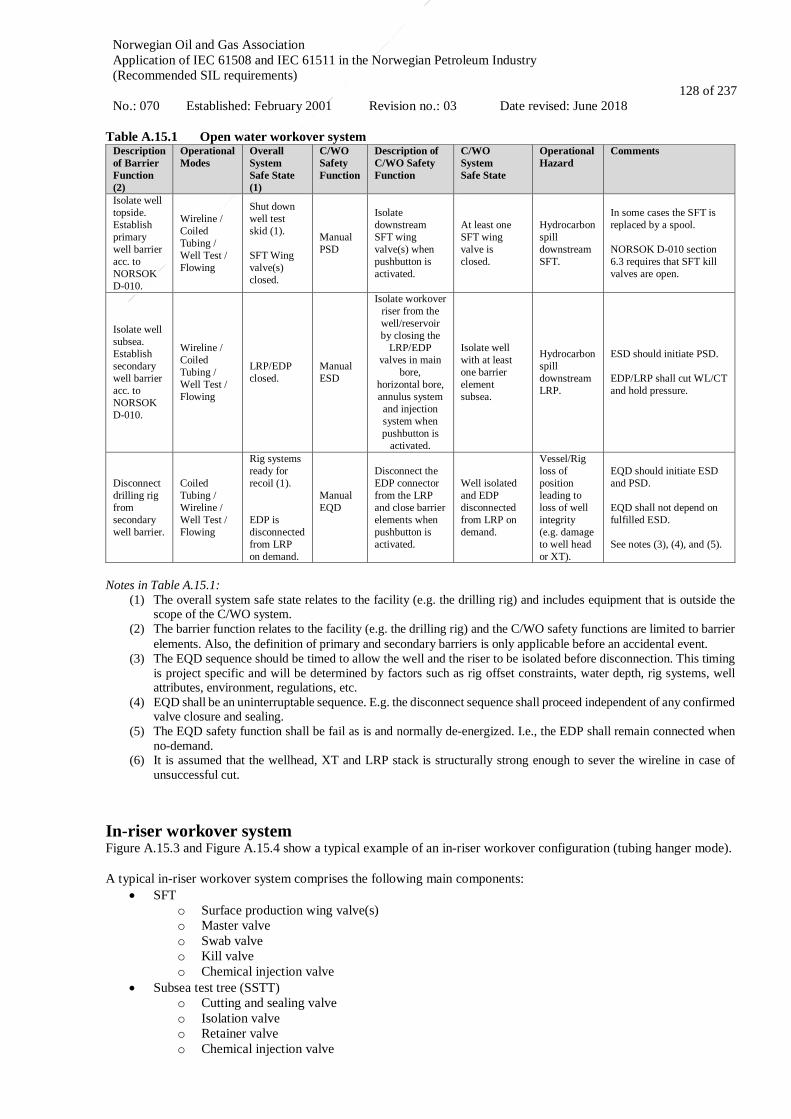
Norwegian Oil and Gas Association Application of IEC 61508 and IEC 61511 in the Norwegian Petroleum Industry (Recommended SIL requirements) No.: 070 Established: February 2001 Revision no.: 03 Date revised: June 2018
128 of 237
Table A.15.1 Open water workover system
Description of Barrier Function (2)
Operational Modes
Overall System Safe State (1)
C/WO Safety Function
Description of C/WO Safety Function
C/WO System Safe State
Operational Hazard
Comments
Isolate well topside. Establish primary well barrier acc. to NORSOK D-010.
Wireline / Coiled Tubing / Well Test / Flowing
Shut down well test skid (1). SFT Wing valve(s) closed.
Manual PSD
Isolate downstream SFT wing valve(s) when pushbutton is activated.
At least one SFT wing valve is closed.
Hydrocarbon spill downstream SFT.
In some cases the SFT is replaced by a spool. NORSOK D-010 section 6.3 requires that SFT kill valves are open.
Isolate well subsea. Establish secondary well barrier acc. to NORSOK D-010.
Wireline / Coiled Tubing / Well Test / Flowing
LRP/EDP closed.
Manual ESD
Isolate workover riser from the well/reservoir by closing the
LRP/EDP valves in main
bore, horizontal bore, annulus system and injection system when pushbutton is
activated.
Isolate well with at least one barrier element subsea.
Hydrocarbon spill downstream LRP.
ESD should initiate PSD. EDP/LRP shall cut WL/CT and hold pressure.
Disconnect drilling rig from secondary well barrier.
Coiled Tubing / Wireline / Well Test / Flowing
Rig systems ready for recoil (1). EDP is disconnected from LRP on demand.
Manual EQD
Disconnect the EDP connector from the LRP and close barrier elements when pushbutton is activated.
Well isolated and EDP disconnected from LRP on demand.
Vessel/Rig loss of position leading to loss of well integrity (e.g. damage to well head or XT).
EQD should initiate ESD and PSD. EQD shall not depend on fulfilled ESD. See notes (3), (4), and (5).
Notes in Table A.15.1:
(1) The overall system safe state relates to the facility (e.g. the drilling rig) and includes equipment that is outside the scope of the C/WO system.
(2) The barrier function relates to the facility (e.g. the drilling rig) and the C/WO safety functions are limited to barrier elements. Also, the definition of primary and secondary barriers is only applicable before an accidental event.
(3) The EQD sequence should be timed to allow the well and the riser to be isolated before disconnection. This timing is project specific and will be determined by factors such as rig offset constraints, water depth, rig systems, well attributes, environment, regulations, etc.
(4) EQD shall be an uninterruptable sequence. E.g. the disconnect sequence shall proceed independent of any confirmed valve closure and sealing.
(5) The EQD safety function shall be fail as is and normally de-energized. I.e., the EDP shall remain connected when no-demand.
(6) It is assumed that the wellhead, XT and LRP stack is structurally strong enough to sever the wireline in case of unsuccessful cut.
In-riser workover system Figure A.15.3 and Figure A.15.4 show a typical example of an in-riser workover configuration (tubing hanger mode). A typical in-riser workover system comprises the following main components:
• SFT o Surface production wing valve(s) o Master valve o Swab valve o Kill valve o Chemical injection valve
• Subsea test tree (SSTT) o Cutting and sealing valve o Isolation valve o Retainer valve o Chemical injection valve

Norwegian Oil and Gas Association Application of IEC 61508 and IEC 61511 in the Norwegian Petroleum Industry (Recommended SIL requirements) No.: 070 Established February 2001 Revision no.: 03 Date revised: June 2018
129 of 237
o Bleed down valve • Landing string (LS) • Marine riser • BOP
The SFT provides the interface to the process plant during a workover operation. The process plant is typically used for well testing after completion and for logging operations during production. The function is the same as for open water workover. The SSTT provides access to the well through the drilling BOP and has the capability to cut the applicable workover tools conveyors (e.g. wireline or coiled tubing) and seal the well main bore (not the annulus) in an emergency. The SSTT is normally located inside the drilling BOP. The SSTT has a latch used for controlled disconnect of the landing string from the SSTT. The landing string is a high pressure riser which incorporates the SSTT as a special joint. Its purpose is to provide a conduit from the well to the surface flow tree. The landing string is run inside the marine riser. The marine riser is a low pressure conduit from the drilling BOP to the rig/vessel and is used primarily for drilling operations. It cannot normally withstand full bore pressure, which is one of the reasons why the landing string is introduced. The landing string SSTT typically only has one valve that can cut and seal. The BOP is the ultimate well control package providing capability of cutting the landing string shear sub (special joint designed to be sheared by the BOP shear seal ram), and seal the well in emergency situations. The BOP can in addition disconnect the marine riser and the landing string (by shearing it) from the well.
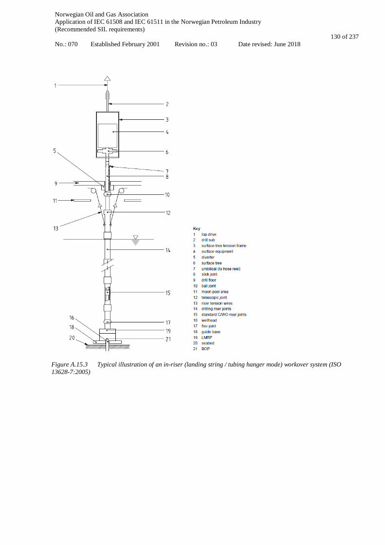
Norwegian Oil and Gas Association Application of IEC 61508 and IEC 61511 in the Norwegian Petroleum Industry (Recommended SIL requirements) No.: 070 Established February 2001 Revision no.: 03 Date revised: June 2018
130 of 237
Figure A.15.3 Typical illustration of an in-riser (landing string / tubing hanger mode) workover system (ISO 13628-7:2005)

Norwegian Oil and Gas Association Application of IEC 61508 and IEC 61511 in the Norwegian Petroleum Industry (Recommended SIL requirements) No.: 070 Established February 2001 Revision no.: 03 Date revised: June 2018
131 of 237
Figure A.15.4 Typical valves for an in-riser (landing string / tubing hanger mode) workover system (ISO 13628-7:2005) The modes of operation that are covered in this section are the following:
• Well test/flowing mode • Coiled tubing mode (includes tubing hanger plug installation mode) • Wireline mode
Note that for "tubing hanger plug installation mode" it is assumed that any tool or "shearable stem", is shearable. For the operations where the "shearable stem" is not shearable, it is assumed that a dispensation to continue operation shall be applied for. Note also that isolation of the riser with the riser retainer valve (RRV) is required to prevent pollution and riser recoil. The RRV function shall be considered in each project specific end-user safety strategy. The following systems and functions are not covered by this section:

Norwegian Oil and Gas Association Application of IEC 61508 and IEC 61511 in the Norwegian Petroleum Industry (Recommended SIL requirements) No.: 070 Established February 2001 Revision no.: 03 Date revised: June 2018
132 of 237
• Riserless light well intervention (RLWI). • Well intervention from jack-up rig involving in-riser system or open water system. • Thru-tubing drilling systems (TTRD). • Automatic EQD. • Automatic riser pressure protection systems. • Tree on wire systems.
Table A.15.2 details the identified SIFs for in-riser workover systems with a description of the barrier, applicable operational modes, functionality, safe state and hazards for in-riser landings string workover system. Table A.15.2 In-riser landing string workover system
Description of Barrier Function (2)
Operational Mode
Overall System Safe State (1)
C/WO Safety Function
Description of C/WO Safety Function
C/WO System Safe State
Operational Hazard
Comments
Isolate well topside. Establish primary well barrier acc. To NORSOK D-010.
Wireline / Coiled Tubing / Well Test / Flowing
Shut down well test skid (1). SFT Wing valve(s) closed.
Manual PSD
Isolate downstream SFT wing valve(s) when pushbutton is activated.
At least one SFT wing valve is closed.
Hydrocarbon spill downstream SFT.
In some cases the SFT is replaced by a spool. NORSOK D-010 section 6.3 requires that SFT kill valves are open.
Isolate well subsea. Establish secondary well barrier acc.to NORSOK D-010.
Wireline / Coiled Tubing / Well Test / Flowing
Annulus isolated by Subsea BOP (1). SSTT closed.
Manual LS ESD
Isolate HP workover riser from the well/reservoir by closing the SSTT valves in main bore when pushbutton is activated.
Isolate production bore with at least one barrier element subsea.
Hydrocarbon spill downstream SSTT.
ESD should initiate PSD. In addition, for operational modes Wireline and Coiled Tubing: SSTT shall cut WL/CT and hold pressure.
(1) The overall system safe state relates to the facility (e.g. the drilling rig) and includes equipment that is outside the scope of the C/WO system.
(2) The barrier function relates to the facility (e.g. the drilling rig) and the C/WO safety functions are limited to barrier elements. Also, the definition of primary and secondary barriers is only applicable before an accidental event.
A.15.1 Subsea workover PSD Definition of functional boundaries The subsea workover PSD function isolates rig and well test unit from the workover riser by closing the production wing side of the SFT when PSD pushbutton is activated. Depending on the SFT design, the function can have one or two wing valves as final elements (illustrated by dashed lines in the RBD in Figure A.15.5). The subsea workover PSD function applies to the following workover operations:
1. Open water workover (riser based workover with high-pressure riser) 2. Landing string (In-riser workover; workover riser through marine riser and BOP)
Basic assumptions:
• Response time is less than process safety time. • Safe state is when at least one SFT wing valve is closed. • This function is de-energized to safe state, meaning the PSD safety function fails to safe state upon loss of
electric signal or hydraulic power • Redundant programmable safety system (PLC and I/O). • Topside PLC's only. • Dual wing valves.
Quantification of safety function

Norwegian Oil and Gas Association Application of IEC 61508 and IEC 61511 in the Norwegian Petroleum Industry (Recommended SIL requirements) No.: 070 Established February 2001 Revision no.: 03 Date revised: June 2018
133 of 237
The reliability block diagram for subsea workover PSD function is presented in Figure A.15.5. The RBD illustrates both a function with redundant (1oo2) wing valves and single wing valve (1oo1). The corresponding resulting PFD calculations are given in Table A.15.3 for redundant wing valves and in Table A.15.4 for single wing valve.
Pushbutton
Logic Solver B
Logic Solver ASFT Wing Valve A
Incl DCV, accumulators
SFT Wing Valve BIncl DCV,
accumulators
CCFLogic solvers
CCFWing valves
Figure A.15.5 RBD for subsea workover PSD function Table A.15.3 PFD input for safety function “open water workover PSD” – redundant wing valves (1oo2)
Component Voting PFD per component PFD CCF Indep.
Pushbutton 1oo1 5.0 ⋅ 10-5 - 5.0 ⋅ 10-5 Redundant programmable safety system (PLC and I/O)
1oo2 3.5 ⋅ 10-3
3.5 ⋅ 10-4
5.3 ⋅ 10-6 Wing valve incl. DCV, accumulators, etc.
1oo2 4.7 ⋅ 10-4 4.7 ⋅ 10-5
Total for function 4.5 ⋅ 10-4 Note that the independent failure contribution is multiplied with a correction factor 4/3 due to assumed simultaneous proof testing (ref. appendix D and Table D.3). Table A.15.4 PFD input for safety function “open water workover PSD” – single wing valve (1oo1)
Component Voting PFD per component PFD CCF Indep.
Pushbutton (incl. contact sets) 1oo1 5.0 ⋅ 10-5 - 5.0 ⋅ 10-5
Redundant programmable safety system (PLC and I/O)
1oo2 3.5 ⋅ 10-3
3.5 ⋅ 10-4 1.6 ⋅ 10-5
Wing valve incl. DCV, accumulators, etc.
1oo1 4.7 ⋅ 10-4 - 4.7 ⋅ 10-4
Total for function 8.9 ⋅ 10-4 Note that the independent failure contribution is multiplied with a correction factor 4/3 due to assumed simultaneous proof testing (ref. appendix D and Table D.3). The following common cause failures are included in the analysis model (with corresponding β-factors):
• Failures affecting logic solvers (10 %) • Failures affecting wing valves (10 %)
The results from above tables indicate that this function may fulfil a quantitative SIL 3 requirement. However, due to architectural requirements, it is reasonable to allocate a SIL 2 requirement to this function.
A.15.2 Open water workover ESD Definition of functional boundaries
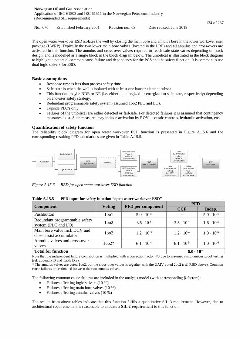
Norwegian Oil and Gas Association Application of IEC 61508 and IEC 61511 in the Norwegian Petroleum Industry (Recommended SIL requirements) No.: 070 Established February 2001 Revision no.: 03 Date revised: June 2018
134 of 237
The open water workover ESD isolates the well by closing the main bore and annulus bore in the lower workover riser package (LWRP). Typically the two lower main bore valves (located in the LRP) and all annulus and cross-overs are activated in this function. The annulus and cross-over valves required to reach safe state varies depending on stack design, and is modelled as a single block in the block diagram below. The umbilical is illustrated in the block diagram to highlight a potential common cause failure and dependency for the PCS and the safety function. It is common to use dual logic solvers for ESD. Basic assumptions
• Response time is less than process safety time. • Safe state is when the well is isolated with at least one barrier element subsea. • This function maybe NDE or NE (i.e. either de-energized or energized to safe state, respectively) depending
on end-user safety strategy. • Redundant programmable safety system (assumed 1oo2 PLC and I/O). • Topside PLC's only. • Failures of the umbilical are either detected or fail-safe. For detected failures it is assumed that contingency
measures exist. Such measures may include activation by ROV, acoustic controls, hydraulic activation, etc. Quantification of safety function The reliability block diagram for open water workover ESD function is presented in Figure A.15.6 and the corresponding resulting PFD calculations are given in Table A.15.5.
Pushbutton
Logic Solver B
Logic Solver A
Umbilical
LRP Main Bore Valve A
Incl DCV, accumulators
LRP Main Bore Valve B
Incl DCV, accumulators
LAIV(LRP Annulus
valve) Incl DCV,
accumulators
UAIV(LRP Annulus
valve )Incl DCV,
accumulators
LXOV(LRP Annulus
valve )Incl DCV,
accumulators
CCFLogic solvers
CCFMain bore valves
CCFLAIV/UAIV
Figure A.15.6 RBD for open water workover ESD function Table A.15.5 PFD input for safety function “open water workover ESD”
Component Voting PFD per component PFD CCF Indep.
Pushbutton 1oo1 5.0 ⋅ 10-5 - 5.0 ⋅ 10-5 Redundant programmable safety system (PLC and I/O) 1oo2 3.5 ⋅ 10-3 3.5 ⋅ 10-4 1.6 ⋅ 10-5
Main bore valve incl. DCV and close assist accumulator 1oo2 1.2 ⋅ 10-3 1.2 ⋅ 10-4 1.9 ⋅ 10-6
Annulus valves and cross-over valves 1oo2* 6.1 ⋅ 10-4 6.1 ⋅ 10-5 1.0 ⋅ 10-6
Total for function 6.0 ⋅ 10-4 Note that the independent failure contribution is multiplied with a correction factor 4/3 due to assumed simultaneous proof testing (ref. appendix D and Table D.3). * The annulus valves are voted 1oo2, but the cross-over valves is together with the UAIV voted 2oo2 (ref. RBD above). Common cause failures are estimated between the two annulus valves. The following common cause failures are included in the analysis model (with corresponding β-factors):
• Failures affecting logic solvers (10 %) • Failures affecting main bore valves (10 %) • Failures affecting annulus valves (10 %)
The results from above tables indicate that this function fulfils a quantitative SIL 3 requirement. However, due to architectural requirements it is reasonable to allocate a SIL 2 requirement to this function.

Norwegian Oil and Gas Association Application of IEC 61508 and IEC 61511 in the Norwegian Petroleum Industry (Recommended SIL requirements) No.: 070 Established February 2001 Revision no.: 03 Date revised: June 2018
135 of 237
A.15.3 Open water workover EQD with isolation Definition of functional boundaries Open water workover EQD disconnects the EDP connector from the LRP and close barrier elements when EQD pushbutton is activated. The EQD function includes closing main bore and annulus bore valves (barrier elements) in addition to disconnecting the EDP from the LRP. Thus, the function includes sealing the well after cutting e.g. coiled tubing and disconnecting the riser system from the well. The sequence of events is project specific. See also the description of the ESD function in section A.15.2 above. Open water workover EQD shall be implemented based on a project specific risk assessment. The risk assessment should at least include the following elements:
• Planned operations • Well conditions • Water depth and rig offset limitations • Rig type (e.g. DP or anchored) • Local regulations • Riser retainer valve function/role
Basic assumptions
• Response time is less than process safety time. • Safe state is when the well is isolated and the EDP is disconnected from LRP on demand. • This function is typically energize to activate, primarily due to risks associated with unintended disconnection.
Simultaneous loss of power and demand is assumed negligible assuming local UPS is available. • Isolation of well (ESD) is activated first and then disconnect from well. • The EQD function shall include a time delay to allow the first barrier element of the ESD sequence to close,
i.e. the EQD sequence should be timed to allow the well and the riser to be isolated before disconnection. EQD shall be an uninterruptable sequence. E.g. the disconnect sequence shall proceed independently of successful closure of LRP and EDP valves.
• Redundant programmable safety system (1oo2 PLC and I/O). • Topside PLC's only.
Quantification of safety function The reliability block diagram for open water workover EQD function is presented in Figure A.15.7, and the corresponding resulting PFD calculations are given in Table A.15.6.
Pushbutton
Logic Solver B
Logic Solver A
Umbilical
Solenoid A
Solenoid B
LRP Main Bore Valve A
LRP Main Bore Valve B
Connector unlock B
Connector unlock A
Connector
LAIV(LRP Annulus
valve) Incl DCV,
accumulators
UAIV(LRP Annulus
valve )Incl DCV,
accumulators
LXOV(LRP Annulus
valve )Incl DCV,
accumulators
CCFLogic solvers
CCFMain bore
valvesCCF
LAIV/UAIV
Figure A.15.7 RBD for open water workover EQD function Table A.15.6 PFD input for safety function “open water workover EQD”
Component Voting PFD per component PFD CCF Indep.
Pushbutton 1oo1 5.0 ⋅ 10-5 - 5.0 ⋅ 10-5 Redundant programmable safety system (PLC and I/O) 1oo2 3.5 ⋅ 10-3 3.5 ⋅ 10-4 1.6 ⋅ 10-5
Main bore valve incl. DCV and close assist accumulator 1oo2 1.2 ⋅ 10-3 1.2 ⋅ 10-4 1.9 ⋅ 10-6
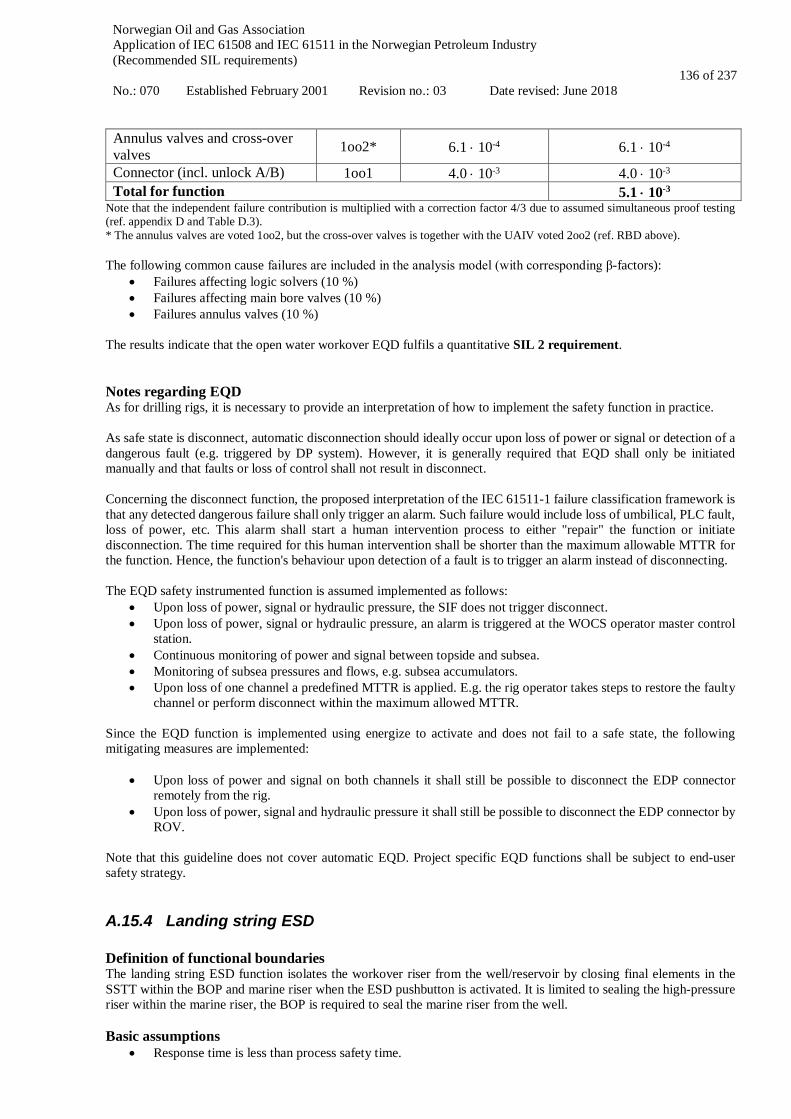
Norwegian Oil and Gas Association Application of IEC 61508 and IEC 61511 in the Norwegian Petroleum Industry (Recommended SIL requirements) No.: 070 Established February 2001 Revision no.: 03 Date revised: June 2018
136 of 237
Annulus valves and cross-over valves 1oo2* 6.1 ⋅ 10-4 6.1 ⋅ 10-4
Connector (incl. unlock A/B) 1oo1 4.0 ⋅ 10-3 4.0 ⋅ 10-3 Total for function 5.1 ⋅ 10-3
Note that the independent failure contribution is multiplied with a correction factor 4/3 due to assumed simultaneous proof testing (ref. appendix D and Table D.3). * The annulus valves are voted 1oo2, but the cross-over valves is together with the UAIV voted 2oo2 (ref. RBD above). The following common cause failures are included in the analysis model (with corresponding β-factors):
• Failures affecting logic solvers (10 %) • Failures affecting main bore valves (10 %) • Failures annulus valves (10 %)
The results indicate that the open water workover EQD fulfils a quantitative SIL 2 requirement. Notes regarding EQD As for drilling rigs, it is necessary to provide an interpretation of how to implement the safety function in practice. As safe state is disconnect, automatic disconnection should ideally occur upon loss of power or signal or detection of a dangerous fault (e.g. triggered by DP system). However, it is generally required that EQD shall only be initiated manually and that faults or loss of control shall not result in disconnect. Concerning the disconnect function, the proposed interpretation of the IEC 61511-1 failure classification framework is that any detected dangerous failure shall only trigger an alarm. Such failure would include loss of umbilical, PLC fault, loss of power, etc. This alarm shall start a human intervention process to either "repair" the function or initiate disconnection. The time required for this human intervention shall be shorter than the maximum allowable MTTR for the function. Hence, the function's behaviour upon detection of a fault is to trigger an alarm instead of disconnecting. The EQD safety instrumented function is assumed implemented as follows:
• Upon loss of power, signal or hydraulic pressure, the SIF does not trigger disconnect. • Upon loss of power, signal or hydraulic pressure, an alarm is triggered at the WOCS operator master control
station. • Continuous monitoring of power and signal between topside and subsea. • Monitoring of subsea pressures and flows, e.g. subsea accumulators. • Upon loss of one channel a predefined MTTR is applied. E.g. the rig operator takes steps to restore the faulty
channel or perform disconnect within the maximum allowed MTTR. Since the EQD function is implemented using energize to activate and does not fail to a safe state, the following mitigating measures are implemented:
• Upon loss of power and signal on both channels it shall still be possible to disconnect the EDP connector remotely from the rig.
• Upon loss of power, signal and hydraulic pressure it shall still be possible to disconnect the EDP connector by ROV.
Note that this guideline does not cover automatic EQD. Project specific EQD functions shall be subject to end-user safety strategy.
A.15.4 Landing string ESD Definition of functional boundaries The landing string ESD function isolates the workover riser from the well/reservoir by closing final elements in the SSTT within the BOP and marine riser when the ESD pushbutton is activated. It is limited to sealing the high-pressure riser within the marine riser, the BOP is required to seal the marine riser from the well. Basic assumptions
• Response time is less than process safety time.
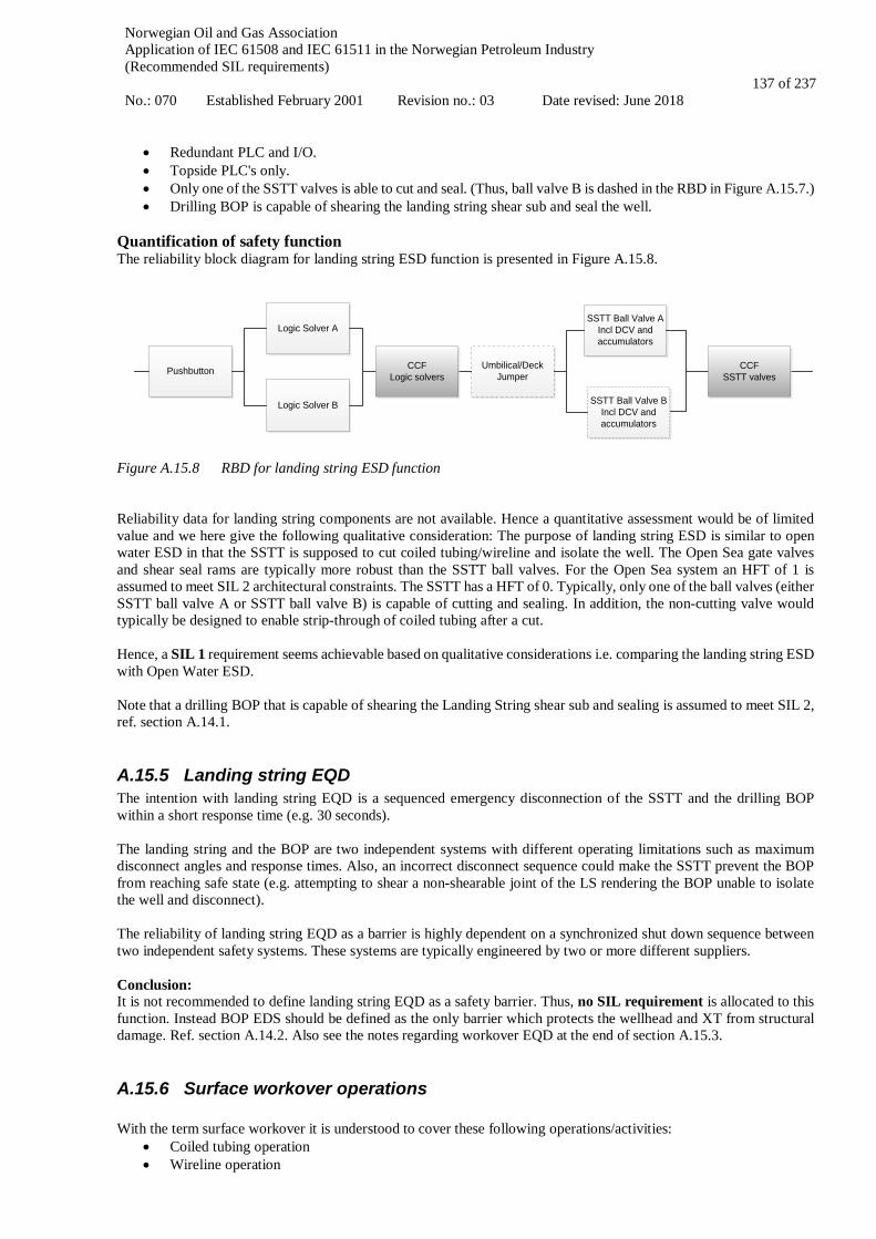
Norwegian Oil and Gas Association Application of IEC 61508 and IEC 61511 in the Norwegian Petroleum Industry (Recommended SIL requirements) No.: 070 Established February 2001 Revision no.: 03 Date revised: June 2018
137 of 237
• Redundant PLC and I/O. • Topside PLC's only. • Only one of the SSTT valves is able to cut and seal. (Thus, ball valve B is dashed in the RBD in Figure A.15.7.) • Drilling BOP is capable of shearing the landing string shear sub and seal the well.
Quantification of safety function The reliability block diagram for landing string ESD function is presented in Figure A.15.8.
Pushbutton
Logic Solver B
Logic Solver A
Umbilical/Deck Jumper
SSTT Ball Valve AIncl DCV and accumulators
SSTT Ball Valve BIncl DCV and accumulators
CCFLogic solvers
CCFSSTT valves
Figure A.15.8 RBD for landing string ESD function Reliability data for landing string components are not available. Hence a quantitative assessment would be of limited value and we here give the following qualitative consideration: The purpose of landing string ESD is similar to open water ESD in that the SSTT is supposed to cut coiled tubing/wireline and isolate the well. The Open Sea gate valves and shear seal rams are typically more robust than the SSTT ball valves. For the Open Sea system an HFT of 1 is assumed to meet SIL 2 architectural constraints. The SSTT has a HFT of 0. Typically, only one of the ball valves (either SSTT ball valve A or SSTT ball valve B) is capable of cutting and sealing. In addition, the non-cutting valve would typically be designed to enable strip-through of coiled tubing after a cut. Hence, a SIL 1 requirement seems achievable based on qualitative considerations i.e. comparing the landing string ESD with Open Water ESD. Note that a drilling BOP that is capable of shearing the Landing String shear sub and sealing is assumed to meet SIL 2, ref. section A.14.1.
A.15.5 Landing string EQD The intention with landing string EQD is a sequenced emergency disconnection of the SSTT and the drilling BOP within a short response time (e.g. 30 seconds). The landing string and the BOP are two independent systems with different operating limitations such as maximum disconnect angles and response times. Also, an incorrect disconnect sequence could make the SSTT prevent the BOP from reaching safe state (e.g. attempting to shear a non-shearable joint of the LS rendering the BOP unable to isolate the well and disconnect). The reliability of landing string EQD as a barrier is highly dependent on a synchronized shut down sequence between two independent safety systems. These systems are typically engineered by two or more different suppliers. Conclusion: It is not recommended to define landing string EQD as a safety barrier. Thus, no SIL requirement is allocated to this function. Instead BOP EDS should be defined as the only barrier which protects the wellhead and XT from structural damage. Ref. section A.14.2. Also see the notes regarding workover EQD at the end of section A.15.3.
A.15.6 Surface workover operations With the term surface workover it is understood to cover these following operations/activities:
• Coiled tubing operation • Wireline operation

Norwegian Oil and Gas Association Application of IEC 61508 and IEC 61511 in the Norwegian Petroleum Industry (Recommended SIL requirements) No.: 070 Established February 2001 Revision no.: 03 Date revised: June 2018
138 of 237
• Snubbing operation
Common for all three operations is that safety head (e.g. shear seal ram) is defined as secondary barrier, while primary barrier is different for all operations, ref. NORSOK D-010. Thus, the following safety functions are included in this guideline:
• Shear seal ram function • Hydraulic master valve (HMV) function
Activation of these functions requires manual initiation. NORSOK D-002 requires a local control panel inside the control cabin for safety heads, and it is assumed that the suggested SIL requirements of the functions are obtained from the remote actuation. Primary barriers Primary barrier for slickline (wireline operations) is stuffing box and GIH (Grease Injection Head) for braided/electrical cable. This barrier is considered more as an operation barrier than safety barrier and performance/integrity requirements for this barrier is described in NORSOK D-002 (e.g. flow, redundancy, control). In order to maintain sealing of the well, the primary barrier needs to run continuously, either pumping grease (GIH) or maintain pressure on stuffing box. Start, stop and control of primary barrier are totally dependent on human interaction, pressure in well and other operational parameters. The primary barrier is to be considered as a continuously operational barrier, which rely on human interpreting well parameters such as flow, pressure, procedures and human control of barrier-integrity. Wireline rams include grease injection to have complete seal of well which is hard to quantify. Thus, no SIL requirement has been allocated to the primary barrier function: Wireline BOP The BOP is installed on top of surface tree and can have different configurations, but minimum requirements are:
• One wireline ram for slickline cable • Double wireline rams for braided/electrical cable
The rams are to be considered as supplement to primary barrier. If primary barrier fails, the operator can close BOP rams in order to maintain sealing of the well until primary barrier is fixed and ready for operation. By closing the BOP rams the operator doesn’t have to close safety head and deal with all the consequences getting back to operation again (expenses/risk). If closing BOP rams is not enough to maintain sufficient sealing of well, the operator would have to activate safety head and shear seal the well. Operational experience Based on operational experience of about 18 000 wireline runs with pressure control equipment, a failure rate of 4.4 ⋅ 10-4 per run was estimated for the primary barrier and a failure rate of 1.1 ⋅ 10-4 per run was estimated for the secondary barrier. It should be noted that this is based on only two events related to the secondary barrier (shear seal ram) and eight events related to the primary barrier.
A.15.7 Shear seal ram function Definition of functional boundaries The shear seal ram can either be part of BOP or stand alone. The shear seal ram is mounted at the bottom of workover rig assembly (closest to wellhead). Shear seal ram is connected to power source (hydraulics) through hoses (two hoses for each ram, open/close or pressure/return). Closing of shear seal ram is possible from control cabin and locally on BCU. Depending on control system design, signal from the pushbutton goes either to a PLC or simpler relay logic, and from there to hydraulic shear seal ram solenoid and valve. Often the operator will also be able to handle hydraulic shear seal ram manually, which then bypass the E/E/PE control system. Example of rig up is given in Figure A.15.9.
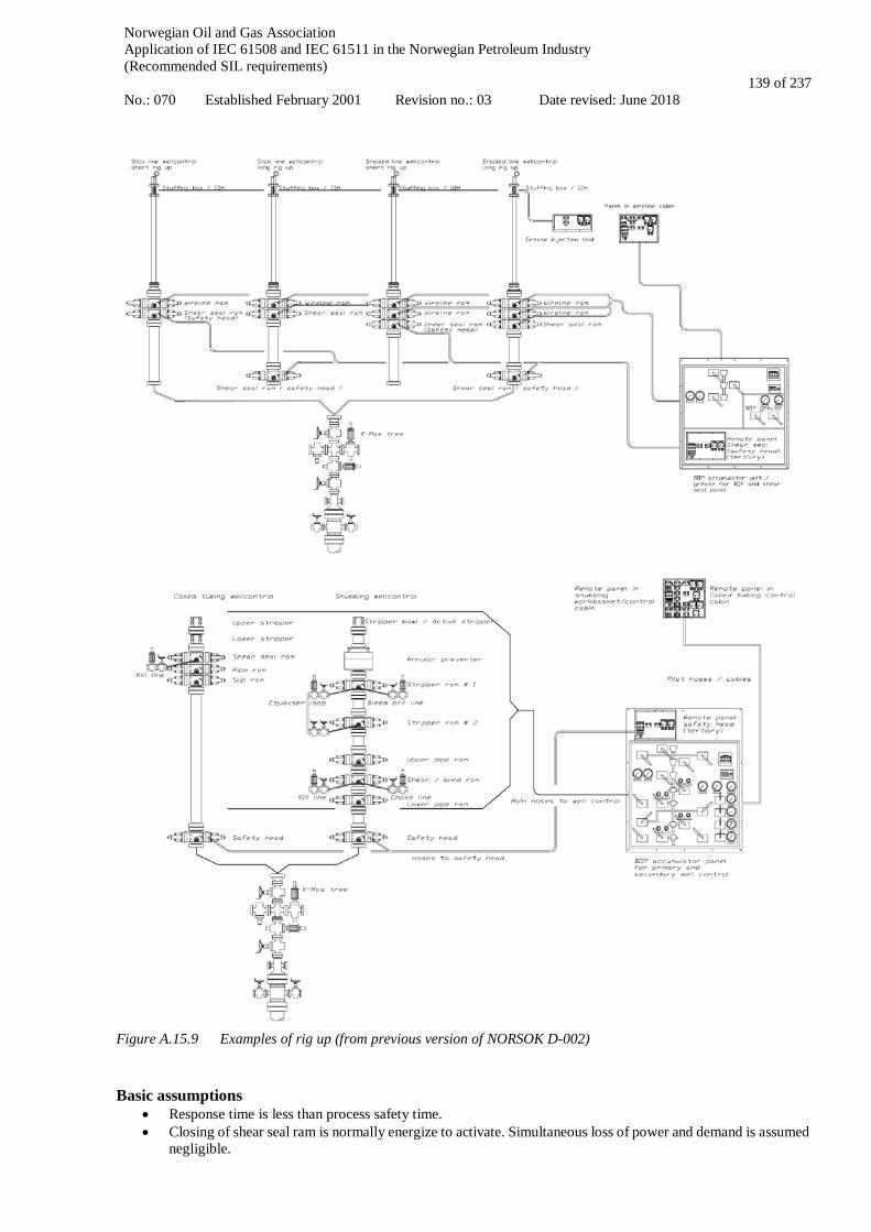
Norwegian Oil and Gas Association Application of IEC 61508 and IEC 61511 in the Norwegian Petroleum Industry (Recommended SIL requirements) No.: 070 Established February 2001 Revision no.: 03 Date revised: June 2018
139 of 237
Figure A.15.9 Examples of rig up (from previous version of NORSOK D-002)
Basic assumptions
• Response time is less than process safety time. • Closing of shear seal ram is normally energize to activate. Simultaneous loss of power and demand is assumed
negligible.

Norwegian Oil and Gas Association Application of IEC 61508 and IEC 61511 in the Norwegian Petroleum Industry (Recommended SIL requirements) No.: 070 Established February 2001 Revision no.: 03 Date revised: June 2018
140 of 237
• PFD contribution from utility systems is not included in total PFD for function, due to extensive diagnostics on fluids, pneumatics, UPS and other required utility-systems.
• Alarms upon failures in utility systems resulting in unavailability of shear seal ram function are required. The same applies for hoses/tubing/fittings/connections for the hydraulic fluid needed to close the shear seal ram.
• Redundant programmable safety system (1oo2 PLC and I/O). • Remote manual actuation of the function.
Quantification of safety function The reliability block diagram for the shear seal ram function is presented in Figure A.15.10 and the corresponding resulting PFD calculations are given in Table A.15.7.
Pushbutton Logic Solver(1oo2) Solenoid Valve Safety head
Shear seal ram
Figure A.15.10 RBD of the shear seal ram function Table A.15.7 PFD input for safety function “shear seal ram”
Component Voting PFD per component PFD CCF Indep.
Pushbutton 1oo1 5.0 ⋅ 10-5 - 5.0 ⋅ 10-5 Redundant programmable safety system (PLC and I/O) 1oo2 3.5 ⋅ 10-3 3.5 ⋅ 10-4 1.6 ⋅ 10-5
Solenoid 1oo1 1.0 ⋅ 10-4 1.0 ⋅ 10-4 Valve 1oo1 3.2 ⋅ 10-4 3.2 ⋅ 10-4 Shear seal ram 1oo1 7.7 ⋅ 10-4 7.7 ⋅ 10-4 Total for function 1.3 ⋅ 10-3
Based on this estimation a SIL 2 requirement can be claimed for shear seal ram function. Note that design differs between various manufacturers and it is up to each manufacturer to ensure sufficient diagnostic/monitoring-strategy on NDE functions, i.e. functions that are energized to safe state.
A.15.8 Hydraulic master valve function Sometimes the operator or facility-owner wants to use HMV in the X-mas tree as safety head. Then the HMV function shall comply with NORSOK D-002. The HMV can be operated from platform system (with local panel(s)) or from a local temporary system. In cases when HMV is activated only for platform systems, see section A.4. Basic assumptions:
• Response time is less than process safety time. • Test interval is one week, i.e. 168 hours, for both components • Remote manual actuation of the function.
Quantification of safety function The reliability block diagram for the HMV function is presented in Figure A.15.11 and the corresponding resulting PFD calculations are given in Table A.15.8.
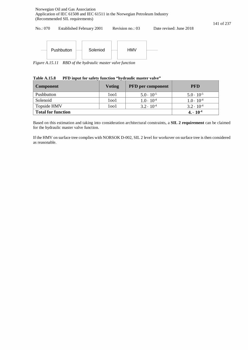
Norwegian Oil and Gas Association Application of IEC 61508 and IEC 61511 in the Norwegian Petroleum Industry (Recommended SIL requirements) No.: 070 Established February 2001 Revision no.: 03 Date revised: June 2018
141 of 237
Soleniod HMVPushbutton
Figure A.15.11 RBD of the hydraulic master valve function Table A.15.8 PFD input for safety function “hydraulic master valve”
Component Voting PFD per component PFD
Pushbutton 1oo1 5.0 ⋅ 10-5 5.0 ⋅ 10-5 Solenoid 1oo1 1.0 ⋅ 10-4 1.0 ⋅ 10-4 Topside HMV 1oo1 3.2 ⋅ 10-4 3.2 ⋅ 10-4 Total for function 4. ⋅ 10-4
Based on this estimation and taking into consideration architectural constraints, a SIL 2 requirement can be claimed for the hydraulic master valve function. If the HMV on surface tree complies with NORSOK D-002, SIL 2 level for workover on surface tree is then considered as reasonable.

Norwegian Oil and Gas Association Application of IEC 61508 and IEC 61511 in the Norwegian Petroleum Industry (Recommended SIL requirements) No.: 070 Established February 2001 Revision no.: 03 Date revised: June 2018
142 of 237
A.16 Manual initiators: ESD and F&G Definition of functional boundaries Following are some of the important manual initiators implemented on an offshore platform. The manual initiator function starts when the buttons have been pushed and ends when the output signal(s) from the safety system has been generated. Some examples of typical functions are:
1. CAP panel pushbutton 2. ESD action initiator pushbutton in field/CCR 3. Firefighting action initiator pushbutton in field/CCR 4. Manual Call Points
Basic assumptions
• Response time is less than process safety time. • Safe state for the installation will be to give a confirmed signal to the logic solver. • The inputs are de-energized to safe state and will upon loss of power go to a safe state. • Single system and I/O.
There shall be a pushbutton in the CAP panel that can initiate actions independent of the programmable systems and bring the installation to a safe state, e.g. disconnection of UPS from CAP pushbutton. Quantification of safety function The reliability block diagram for this function is presented in Figure A.16.1. The PFD calculations are given in Table A.16.1
Pushbutton Logic
Figure A.16.1 RBD for the "manual initiation of ESD/F&G" sub-function. Table A.16.1 PFD results for a "manual initiation of ESD/F&G" sub-function.
Component Voting PFD ESD F&G
Manual pushbutton 1oo1 1.3 ⋅ 10-3 1.3 ⋅ 10-3 Logic incl. I/O 1oo1 3.5 ⋅ 10-3 3.5 ⋅ 10-3 Total for function 4.8 ⋅ 10-3 4.8 ⋅ 10-3
Based on this estimation a SIL 2 requirement can be claimed for manual initiation of F&G and ESD functions from the field or from the CCR.
Norwegian Oil and Gas Association Application of IEC 61508 and IEC 61511 in the Norwegian Petroleum Industry (Recommended SIL requirements) No.: 070 Established February 2001 Revision no.: 03 Date revised: June 2018
143 of 237
A.17 References /A.1/ S. Håbrekke, S. Hauge and T. Onshus: Reliability Data for Safety Instrumented Systems – PDS Data Handbook
2013 Edition, SINTEF Report no. A24443, ISBN 978-82-536-1334-5 /A.2/ Scandpower: Blowout and well release frequencies based on SINTEF offshore blowout database 2010
(revised), Rev. no. Final B, Report no. 19.101.001-3009/2011/R3, 2011-04-05 /A.3/ S. Hauge, T. Kråkenes, P. Hokstad, S. Håbrekke and H. Jin: Reliability Prediction Method for Safety
Instrumented Systems – PDS Method Handbook 2013, SINTEF report no. A24442, ISBN 978-82-536-1333-8
/A.4/ OREDA handbook 2002. Offshore Reliability Data, 4th Edition. /A.5/ OREDA handbooks 2009. Offshore Reliability Data, 5th Edition, Volume 1 – Topside Equipment and Volume
2 – Subsea Equipment /A.6/ OREDA handbooks 2015. Offshore and Onshore Reliability Data, 6th Edition, Volume 1 – Topside Equipment
and Volume 2 – Subsea Equipment

Norwegian Oil and Gas Association Application of IEC 61508 and IEC 61511 in the Norwegian Petroleum Industry (Recommended SIL requirements) No.: 070 Established: February 2001 Revision no.: 03 Date revised: June 2018
144 of 237
APPLICATION OF IEC 61508 AND IEC 61511
IN THE NORWEGIAN PETROLEUM INDUSTRY
(Recommended SIL requirements)
Appendix B
SAFETY INSTRUMENTED OVERPRESSURE PROTECTION OF VESSEL WITH SEVERAL INLETS

Norwegian Oil and Gas Association Application of IEC 61508 and IEC 61511 in the Norwegian Petroleum Industry (Recommended SIL requirements) No.: 070 Established: February 2001 Revision no.: 03 Date revised: June 2018
145 of 237
CONTENT
B.1 INTRODUCTION ..................................................................................................................................... 146
B.1.1 RELIABILITY DATA ............................................................................................................................... 146 B.1.2 ACCEPTANCE CRITERION ...................................................................................................................... 146 B.1.3 PFD REQUIREMENT TO THE SIF ............................................................................................................ 147 B.1.4 IDENTIFYING INITIATING EVENTS AND PROTECTIVE LAYERS .................................................................. 147
B.2 EXAMPLES .............................................................................................................................................. 148 B.2.1 SEPARATOR WITH SINGLE INLET ........................................................................................................... 148 B.2.2 SEPARATOR WITH TWO INLETS .............................................................................................................. 150 B.2.3 PRESSURE VESSEL WITH FOUR INLETS ................................................................................................... 151 B.2.4 PRESSURE VESSEL WITH THREE INLETS, 2 PSVS, NO PCS CREDIT........................................................... 151 B.2.5 PRESSURE VESSEL WITH SIX INLETS, TWO PSVS, NO PCS CREDIT .......................................................... 151 B.2.6 GENERIC CALCULATIONS ...................................................................................................................... 152

Norwegian Oil and Gas Association Application of IEC 61508 and IEC 61511 in the Norwegian Petroleum Industry (Recommended SIL requirements) No.: 070 Established: February 2001 Revision no.: 03 Date revised: June 2018
146 of 237
B.1 Introduction This appendix is referred to in section A.3 concerning PSD functions / primary protections (PAHH, LAHH). It provides an example of how to perform a risk-based SIL allocation in case the typical PFD given in table 7.5.1 and described in A.3 cannot be achieved due to several inlets needed to be closed to reach the safe state. The examples given are in the low complexity range of separator configurations, assuming that primary protection and secondary protection, each and independently have capacity to prevent pressure above test pressure. I.e., the vessel is designed with conventional pressure protection covering all initiating events. Note: The PSV shall be designed according to API Standard 521 ("Pressure-relieving and Depressuring Systems"). The set point shall be such that the accumulated pressure is within the code accepted pressure (normally much below the test pressure).
B.1.1 Reliability data The following failure data has been applied in the calculations (annual testing assumed): Table B.1 Failure data from PDS data handbook 2013, annual testing
Component Failure rate [per hour] PFD 𝜷𝜷
PT 5.0 ⋅ 10-7 2.2 ⋅ 10-3 0.06 LT 1.0 ⋅ 10-6 4.4 ⋅ 10-3 - Logics 8.0 ⋅ 10-7 3.5 ⋅ 10-3 0.05 Solenoid/pilot 6.0 ⋅ 10-7 2.6 ⋅ 10-3 0.05 / 0.10 ESV/XV 1.9 ⋅ 10-6 8.3 ⋅ 10-3 0.05 PSV (test pressure) 1.1 ⋅ 10-6 4.8 ⋅ 10-3 0.05
B.1.2 Acceptance criterion Rupture of a pressure vessel carrying hydrocarbons is an event which potential in general exceeds the design accidental loads of an installation. An acceptance criterion for such an event (rupture) should therefore be low. Although the design is conventional in the present example, it is proposed to use a similar acceptance criterion as the one given in NORSOK S-001 for non-conventional designs, i.e. the annual probability of rupture due to overpressure shall be less than 10-5 per process segment. The above acceptance criteria is informative, and used for illustration in the example developed here. Other well-founded acceptance criteria may be applied. It is further assumed that:
• the vessel is not de-rated (metal yield strength is still within design assumptions) • the probability of rupture at test pressure is equal to 1
Depending on the vessel design integrity and condition, rupture may occur at a higher pressure than test pressure (or at lower pressure if the vessel is de-rated). The acceptance criterion therefore becomes: the annual probability of exceeding test pressure shall be less than 10-5 per process segment. For a vessel with conventional pressure protection, the Hazard Rate is calculated as follows (assuming independency between the PSD and the PSV protection layers):
HR = DR ⋅ PFDPSD ⋅ PFDPSV Here, DR is the demand rate on the PAHH function and PFDPSD and PFDPSV is the probability of failure on demand for PSD (PAHH function) and PSVs, respectively.
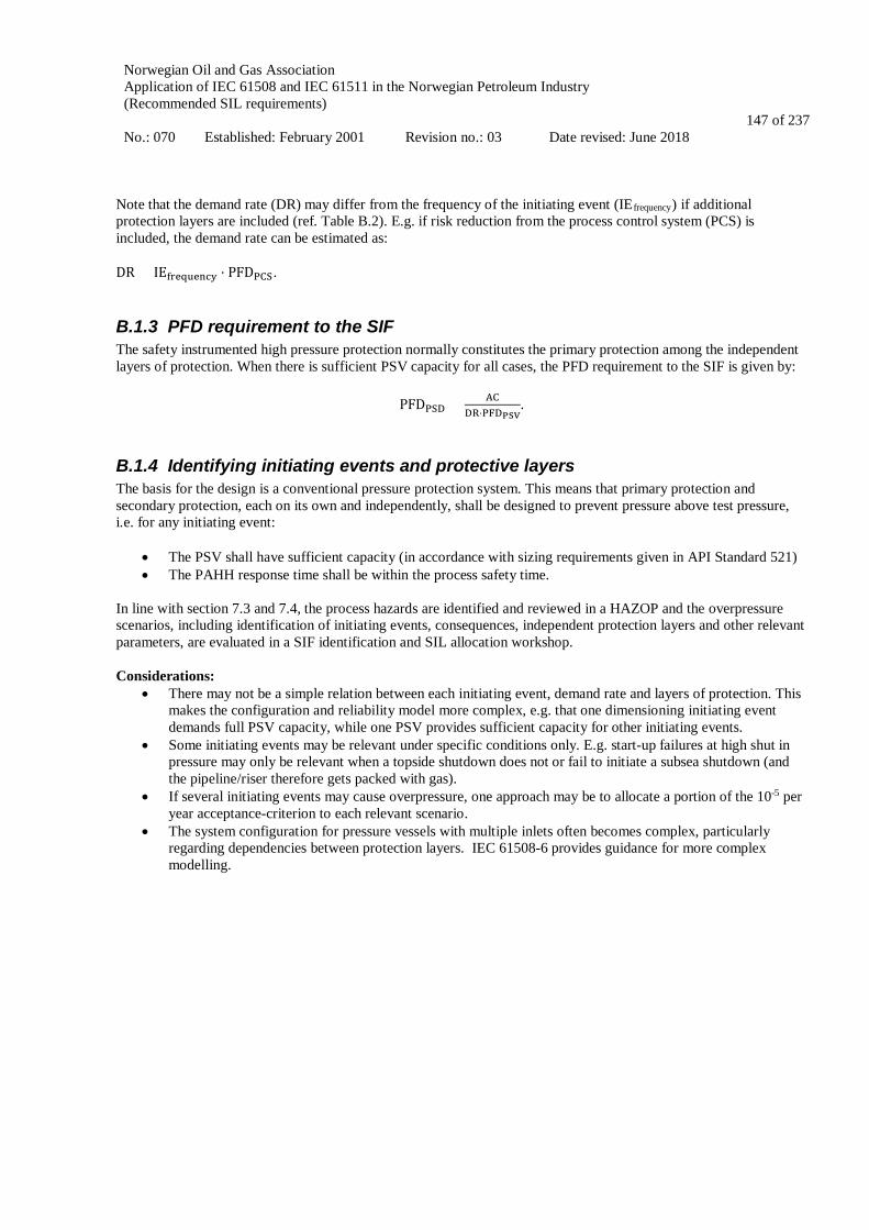
Norwegian Oil and Gas Association Application of IEC 61508 and IEC 61511 in the Norwegian Petroleum Industry (Recommended SIL requirements) No.: 070 Established: February 2001 Revision no.: 03 Date revised: June 2018
147 of 237
Note that the demand rate (DR) may differ from the frequency of the initiating event (IEfrequency) if additional protection layers are included (ref. Table B.2). E.g. if risk reduction from the process control system (PCS) is included, the demand rate can be estimated as: DR = IEfrequency ⋅ PFDPCS.
B.1.3 PFD requirement to the SIF The safety instrumented high pressure protection normally constitutes the primary protection among the independent layers of protection. When there is sufficient PSV capacity for all cases, the PFD requirement to the SIF is given by:
PFDPSD < ACDR⋅PFDPSV
.
B.1.4 Identifying initiating events and protective layers The basis for the design is a conventional pressure protection system. This means that primary protection and secondary protection, each on its own and independently, shall be designed to prevent pressure above test pressure, i.e. for any initiating event:
• The PSV shall have sufficient capacity (in accordance with sizing requirements given in API Standard 521) • The PAHH response time shall be within the process safety time.
In line with section 7.3 and 7.4, the process hazards are identified and reviewed in a HAZOP and the overpressure scenarios, including identification of initiating events, consequences, independent protection layers and other relevant parameters, are evaluated in a SIF identification and SIL allocation workshop. Considerations:
• There may not be a simple relation between each initiating event, demand rate and layers of protection. This makes the configuration and reliability model more complex, e.g. that one dimensioning initiating event demands full PSV capacity, while one PSV provides sufficient capacity for other initiating events.
• Some initiating events may be relevant under specific conditions only. E.g. start-up failures at high shut in pressure may only be relevant when a topside shutdown does not or fail to initiate a subsea shutdown (and the pipeline/riser therefore gets packed with gas).
• If several initiating events may cause overpressure, one approach may be to allocate a portion of the 10-5 per year acceptance-criterion to each relevant scenario.
• The system configuration for pressure vessels with multiple inlets often becomes complex, particularly regarding dependencies between protection layers. IEC 61508-6 provides guidance for more complex modelling.

Norwegian Oil and Gas Association Application of IEC 61508 and IEC 61511 in the Norwegian Petroleum Industry (Recommended SIL requirements) No.: 070 Established: February 2001 Revision no.: 03 Date revised: June 2018
148 of 237
B.2 Examples
B.2.1 Separator with single inlet This first example is a simple case with a brief evaluation of initiating events and barriers (see table B.2). The following describes the system configuration:
• Process control: Process control valve in gas outlet line opens to flare • Primary protection (PSD): PAHH 1oo1; Logic 1oo1; Solenoid/Pilot 1oo1; XV 1oo1 • Secondary protection: PSV 1oo1
System analysis:
• PCS (PCV opens to flare) has capacity to control pressure in a blocked outlet situation. • Blocked liquid outlet will cause overfilling of the vessel with liquid entrainment downstream and likely
closure of the gas outlet / overpressure in the vessel when reaching overfill level or when gas outlet is blocked. Response time of the PAHH with liquid filled vessel may not sufficient. The primary protection for this scenario may therefore rely primarily on the LAHH.
• The PSV have sufficient capacity for all cases (choke collapse, block valve mal-operation, two phase flow due to both liquid and gas outlets blocked). The PAHH response time is within the process safety time, i.e. quick enough to prevent the pressure from exceeding the test pressure (process safety time may have to be modelled by dynamic analysis to verify this assumption is fulfilled).
• PCS and PSD are independent (physically separated) but not functionally diverse in PT and logic. To compensate, spill off valve is fail safe, opens on high pressure or compressor trip signal. PCS is considered sufficiently independent from compressor trip scenarios.
• In case of PCS failure (control valve stuck in closed position), there is not sufficient reaction time for human intervention.
Table B.2 shows the calculated hazard rate for each initiating event and relevant protective layers.
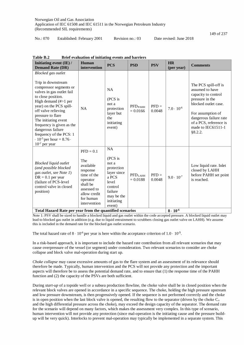
Norwegian Oil and Gas Association Application of IEC 61508 and IEC 61511 in the Norwegian Petroleum Industry (Recommended SIL requirements) No.: 070 Established: February 2001 Revision no.: 03 Date revised: June 2018
149 of 237
Table B.2 Brief evaluation of initiating events and barriers
Initiating event (IE) / Demand Rate (DR)
Human intervention PCS PSD PSV HR
(per year) Comments
Blocked gas outlet Trip in downstream compressor segments or valves in gas outlet fail to close position. High demand (#>1 per year) on the PCS spill-off valve relieving pressure to flare The initiating event frequency is given as the dangerous failure frequency of the PCS: 1 ⋅ 10-5 per hour = 8.76 ⋅ 10-2 per year
NA
NA (PCS is not a protection layer but the initiating event)
PFDPAHH = 0.0166
PFD = 0.0048 7.0 ⋅ 10-6
The PCS spill-off is assumed to have capacity to control pressure in the blocked outlet case. For assumption of dangerous failure rate of a PCS, reference is made to IEC61511-1 §8.2.2.
Blocked liquid outlet (and possible blocked gas outlet, see Note 1) DR = 0.1 per year (failure of PCS-level control valve in closed position)
PFD = 0.1 The available response time of the operator shall be assessed to allow credit for human intervention
NA (PCS is not a protection layer since a PCS level control failure may be the initiating event)
PFDLAHH = 0.0188
PFD = 0.0048 9.0 ⋅ 10-7
Low liquid rate. Inlet closed by LAHH before PAHH set point is reached.
Total Hazard Rate per year from the quantified scenarios 8 ⋅ 10-6 Note 1: PSV shall be sized to handle a blocked liquid and gas outlet within the code accepted pressure. A blocked liquid outlet may lead to blocked gas outlet in addition (e.g. due to liquid entrainment to scrubbers closing gas outlet valve on LAHH). We assume this is included in the demand rate for the blocked gas outlet scenario. The total hazard rate of 8 ⋅ 10-6 per year is here within the acceptance criterion of 1.0 ⋅ 10-5. In a risk-based approach, it is important to include the hazard rate contribution from all relevant scenarios that may cause overpressure of the vessel (or segment) under consideration. Two relevant scenarios to consider are choke collapse and block valve mal-operation during start up. Choke collapse may cause excessive amounts of gas to the flare system and an assessment of its relevance should therefore be made. Typically, human intervention and the PCS will not provide any protection and the important aspects will therefore be to assess the potential demand rate, and to ensure that (1) the response time of the PAHH function and (2) the capacity of the PSVs are both sufficient. During start-up of a topside well or a subsea production flowline, the choke valve shall be in closed position when the relevant block valves are opened in accordance in a specific sequence. The choke, holding the high pressure upstream and low pressure downstream, is then progressively opened. If the sequence is not performed correctly and the choke is in open position when the last block valve is opened, the resulting flow to the separator (driven by the choke Cv and the high differential pressure across the choke), may exceed the design capacity of the separator. The demand rate for the scenario will depend on many factors, which makes the assessment very complex. In this type of scenario, human intervention will not provide any protection (since mal-operation is the initiating cause and the pressure build-up will be very quick). Interlocks to prevent mal-operation may typically be implemented in a separate system. This

Norwegian Oil and Gas Association Application of IEC 61508 and IEC 61511 in the Norwegian Petroleum Industry (Recommended SIL requirements) No.: 070 Established: February 2001 Revision no.: 03 Date revised: June 2018
150 of 237
may be an interlock on valve limit switch to ensure correct valve position in the opening sequence (and/or a check of differential pressure across the valve). In addition, it should be considered whether (1) the response time of the PAHH function and/or (2) the capacity of the PSVs are both sufficient during the relevant start-up failure scenarios. When assessing the potential relief flow required for the separators PSV to protect against this block-valve mal-operation scenario, we need to consider:
- The well shut-in pressure for topside wells - The maximum operating pressure for subsea production flowlines
It should then be documented that the contribution from choke collapse and start-up failures are sufficiently remote for the total hazard rate to be within the acceptance criterion. Additional notes:
• The average frequency of dangerous failures of a PCS as an initiating source shall not be assumed to be <10-
5 per hour (IEC 61511-1 ch.8.2.2). • The PCS can be considered as potential mean of reducing the demand rate if the latter is not affected by
failures in the PCS. The risk reduction claimed for a PCS protection layer shall be ≤10 (PFD ≥ 0.1). (IEC 61511-1 ch.9.3.2).
• PFD for operator response to alarms can be assumed 10-1 (IEC 61511-3 table F4.1) • If PSD and PSV are tested simultaneously, this systematic dependency gives a PFD (and HR) 33 % higher
due to Cauchy–Schwarz inequality. • In the blocked liquid and gas outlet scenarios (cf. Table B.2), the final elements of the SIFs (PAHH, LAHH)
will include the valves/breakers necessary for the isolation/trip of all critical inlets to the separator with potential for overpressure/overfilling.
• For the choke collapse and the block valve mal-operation scenarios, the credible scenario only considers one choke collapse (respectively one inlet block valve mal-operation) at a time. Therefore, the final elements of the corresponding SIF will include the valves necessary for the isolation of one inlet.
• One SIF per inlet with potential for overpressure by choke collapse, respectively by block valve mal-operation should be defined.
B.2.2 Separator with two inlets System configuration:
• The same configuration assumed as in example B.6, but with two inlets. One valve per inlet. • PCS (PCV opens to flare) has capacity to control pressure in a blocked outlet situation. • PSD and PSV have capacity to handle all relevant high pressure cases.
Calculations: (limited to blocked gas outlet case):
DRPCS = 0.088 per year PFDPSD = 0.0276 PFDPSV = 0.0048 HR = DR ⋅ PFDPSD ⋅ PFDPSV = 1.17 ⋅ 10−5 per year, which is slightly above the acceptance criterion
Other measures, such as closing additional inlet valves (e.g. production wing valves), will be necessary to meet the acceptance criterion. In such cases, the process simulations and reliability calculations should verify the capability of the additional protection measures. The system configuration becomes more complex, particularly regarding dependencies. IEC 61508-6 provides guidance for more complex modelling. Comment: If several initiating events may cause overpressure, one approach may be to allocate a portion of the 10-5 acceptance-criterion to each relevant scenario.

Norwegian Oil and Gas Association Application of IEC 61508 and IEC 61511 in the Norwegian Petroleum Industry (Recommended SIL requirements) No.: 070 Established: February 2001 Revision no.: 03 Date revised: June 2018
151 of 237
B.2.3 Pressure vessel with four inlets System configuration:
• The same configuration as in example B.6 assumed, but with four inlets. One valve per inlet. • PCS (PCV opens to flare) has capacity to control pressure in a blocked outlet situation. • PSD and PSV have capacity to handle all relevant high pressure cases.
Calculations: (limited to blocked gas outlet case):
DRPCS = 0.088 per year PFDPSD = 0.050 PFDPSV = 0.0048 HR = DR ⋅ PFDPSD ⋅ PFDPSV = 2.1 ⋅ 10−5 per year, which is twice the acceptance criterion.
Other measures, such as closing additional inlet valves (e.g. production wing valves), will be necessary to meet the acceptance criterion.
B.2.4 Pressure vessel with three inlets, 2 PSVs, no PCS credit No credit is given to the PCS. The demand rate needs to be individually assessed but is here assumed to be one per 10th year. The following describes the configuration:
• Instant blocking of all possible outlets • Three inlets, each with one valve • Non redundant PSD function • Two PSV’s, one PSV is sufficient to relief inflow at test pressure (1oo2 configuration, 10% β-factor assumed
for PSVs) • PSD fast enough to avoid test pressure with blocked PSV • PSD and PSV are totally independent
Note: The PSVs are sized in accordance with API 521. The set point shall be such that the accumulated pressure is within the code accepted pressure (normally much below the test pressure). The blocked outlet case is generally not the dimensioning scenario (choke collapse or start-up failure typically require much larger capacity). Installed capacity for one of the PSVs is assumed sufficient for the blocked outlet case at test pressure in the present example. Calculation:
DRPCS = 0.1 per year PFDPSD = 0.0384 PFDPSV = 0.00024 HR = DR ⋅ PFDPSD ⋅ PFDPSV = 1 ⋅ 10−6 per year, being within the acceptance criterion.
B.2.5 Pressure vessel with six inlets, two PSVs, no PCS credit No credit is given to the PCS. The demand rate needs to be individually assessed, but is here assumed to be one per 10th year. The following describes the configuration:
Norwegian Oil and Gas Association Application of IEC 61508 and IEC 61511 in the Norwegian Petroleum Industry (Recommended SIL requirements) No.: 070 Established: February 2001 Revision no.: 03 Date revised: June 2018
152 of 237
• Instant blocking of all possible outlets • Six inlets both with one valve • Non redundant PSD function • Two PSV’s, one PSV is sufficient to relief inflow at test pressure (1oo2 configuration, 10% β-factor assumed
for PSVs) • PSD fast enough to avoid test pressure with blocked PSV • PSD and PSV are totally independent
Calculation:
DRPCS = 0.1 per year PFDPSD = 0.0713 PFDPSV = 0.00024 HR = DR ⋅ PFDPSD ⋅ PFDPSV = 2 ⋅ 10−6 per year, again being within the acceptance criterion.
B.2.6 Generic calculations The above calculations of the hazard rate are examples with various combinations of demand rate, PSD functions and PSV configurations. The demand rate frequency and the PFD of the PSD and PSV configurations will decide whether the overpressure acceptance criterion of 1.0 ⋅ 10-5 per year can be met. Figure B.1 below shows combinations of the factors that meet the criterion. Each line represents a PSV configuration with the PFD calculated based on PDS 2013 data assuming that PSVs open before test pressure. Combinations of demand rate and PFDPSD below the lines are within the acceptance criterion. Examples on how to interpret Figure B.1
1. Consider a PSV configuration of 1oo2 (uppermost line). The demand rate is 1 per year. The acceptance criterion is met if the PFD of the PSD function is less than approximately 3.5 ⋅ 10-2.
2. Consider a PSV configuration of 1oo1. The PFD of the PSD function is 4 ⋅ 10-2. The acceptance criterion is
met if the demand rate is less than approximately 0.05 per year.
3. Consider a demand rate of 0.1 per year. The PFD of the PSD function is 4 ⋅ 10-2. The acceptance criterion is met for any redundant PSV configuration (1oo2, 2oo3, 3oo4).
Note that the figure may be used as a quick reference to consider acceptable combinations of demand rate and probability of failure of PSD and PSV. However, in order to check that the acceptance criterion is met, it is recommended to calculate the hazard rate for each individual case.

Norwegian Oil and Gas Association Application of IEC 61508 and IEC 61511 in the Norwegian Petroleum Industry (Recommended SIL requirements) No.: 070 Established: February 2001 Revision no.: 03 Date revised: June 2018
153 of 237
Figure B.1 Combinations of demand rates and PFD of the PSD function that meet an acceptance criterion of
1.0 ⋅ 10-5 per year for various PSV configurations Warning note: The PSVs are sized in accordance with API 521. The set point shall be such that the accumulated pressure is within the code accepted pressure (normally much below the test pressure). The blocked outlet case is generally not the dimensioning scenario (choke collapse or start-up failure typically require much larger capacity). Redundancy claims may therefore be made considering the installed capacity per PSV in service when accumulation reaches test pressure and the necessary capacity for the blocked outlets scenario at test pressure. Some of the PSV configurations in Figure B.1 may be very uncommon but is here included mainly for the purpose of illustration.
Norwegian Oil and Gas Association Application of IEC 61508 and IEC 61511 in the Norwegian Petroleum Industry (Recommended SIL requirements) No.: 070 Established: February 2001 Revision no.: 03 Date revised: June 2018
154 of 237
APPLICATION OF IEC 61508 AND IEC 61511
IN THE NORWEGIAN PETROLEUM INDUSTRY
(Recommended SIL requirements)
Appendix C
CHANGES FROM PREVIOUS VERSIONS OF GUIDELINE

Norwegian Oil and Gas Association Application of IEC 61508 and IEC 61511 in the Norwegian Petroleum Industry (Recommended SIL requirements) No.: 070 Established: February 2001 Revision no.: 03 Date revised: June 2018
155 of 237
CONTENT
C.1 INTRODUCTION ..................................................................................................................................... 156
C.2 TABLE OF MAIN CHANGES ................................................................................................................ 157
Norwegian Oil and Gas Association Application of IEC 61508 and IEC 61511 in the Norwegian Petroleum Industry (Recommended SIL requirements) No.: 070 Established: February 2001 Revision no.: 03 Date revised: June 2018
156 of 237
C.1 Introduction In this appendix the main changes to this version of the guideline as compared to the previous revision no. 02 (2004) are described. Included in the description is a discussion and justification of the changes, as well as an evaluation of the impacts of the changes. The general approach in Norwegian Oil and Gas' Guideline 070 (NOG 070) is:
• Define a safety function that is generally accepted as a good solution giving adequate protection; • Document the average performance achieved by this function (by using historic field data) and reflect this
performance in terms of PFD/SIL requirements in accordance with IEC 61511; • By providing such general performance requirements, equipment and loop design can be standardised to
meet these requirements; • Focus and resources can then rather be directed towards specific hazards and situations where these standard
functions are not applicable. The justifications and evaluations of the changes made to this guideline should be viewed in the light of the following aspects:
• Fulfilment of the PSA Management regulations section 5 on barriers is mandatory for all oil & gas activity in Norway. It is here stated that verifiable performance requirements shall be defined for all barrier elements.
• For safety instrumented systems (SIS), PSA refers to IEC 61511, IEC 61508 and the NOG 070 as standards and guidelines that should be applied for establishing such performance requirements.
• Revision 2 of the NOG 070 (2004) is the basis for the discussed changes.
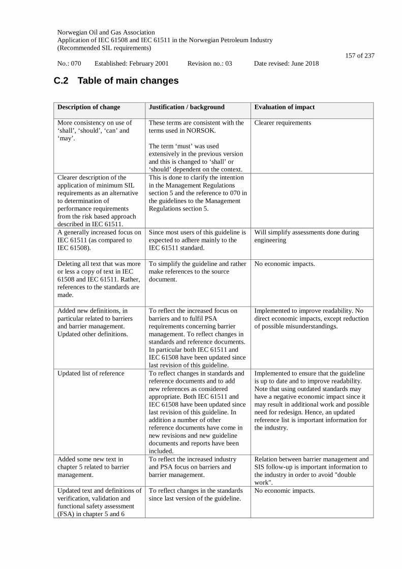
Norwegian Oil and Gas Association Application of IEC 61508 and IEC 61511 in the Norwegian Petroleum Industry (Recommended SIL requirements) No.: 070 Established: February 2001 Revision no.: 03 Date revised: June 2018
157 of 237
C.2 Table of main changes
Description of change
Justification / background Evaluation of impact
More consistency on use of ‘shall’, ‘should’, ‘can’ and ‘may’.
These terms are consistent with the terms used in NORSOK. The term ‘must’ was used extensively in the previous version and this is changed to ‘shall’ or ‘should’ dependent on the context.
Clearer requirements
Clearer description of the application of minimum SIL requirements as an alternative to determination of performance requirements from the risk based approach described in IEC 61511.
This is done to clarify the intention in the Management Regulations section 5 and the reference to 070 in the guidelines to the Management Regulations section 5.
A generally increased focus on IEC 61511 (as compared to IEC 61508).
Since most users of this guideline is expected to adhere mainly to the IEC 61511 standard.
Will simplify assessments done during engineering
Deleting all text that was more or less a copy of text in IEC 61508 and IEC 61511. Rather, references to the standards are made.
To simplify the guideline and rather make references to the source document.
No economic impacts.
Added new definitions, in particular related to barriers and barrier management. Updated other definitions.
To reflect the increased focus on barriers and to fulfil PSA requirements concerning barrier management. To reflect changes in standards and reference documents. In particular both IEC 61511 and IEC 61508 have been updated since last revision of this guideline.
Implemented to improve readability. No direct economic impacts, except reduction of possible misunderstandings.
Updated list of reference
To reflect changes in standards and reference documents and to add new references as considered appropriate. Both IEC 61511 and IEC 61508 have been updated since last revision of this guideline. In addition a number of other reference documents have come in new revisions and new guideline documents and reports have been included.
Implemented to ensure that the guideline is up to date and to improve readability. Note that using outdated standards may have a negative economic impact since it may result in additional work and possible need for redesign. Hence, an updated reference list is important information for the industry.
Added some new text in chapter 5 related to barrier management.
To reflect the increased industry and PSA focus on barriers and barrier management.
Relation between barrier management and SIS follow-up is important information to the industry in order to avoid "double work".
Updated text and definitions of verification, validation and functional safety assessment (FSA) in chapter 5 and 6
To reflect changes in the standards since last version of the guideline.
No economic impacts.

Norwegian Oil and Gas Association Application of IEC 61508 and IEC 61511 in the Norwegian Petroleum Industry (Recommended SIL requirements) No.: 070 Established: February 2001 Revision no.: 03 Date revised: June 2018
158 of 237
Description of change
Justification / background Evaluation of impact
Deleted section in chapter 7 about definition of EUC (equipment under control)
The concept of EUC is not used in IEC 61511. We rather use the IEC 61511 terminology of "process" where appropriate. Otherwise, the description of the safety function (ref. Appendix A) will clarify its purpose and what is to be protected.
No economic impacts.
Updated section in chapter 7 about definition of safety functions and SIL allocation
Improvement of text and further alignment with IEC 61511.
No economic impacts.
Updated table 7.1 of minimum SIL/PFD requirements. Updated some of the requirements and included new functions (ref. Table 1.1).
These updates are based on new operational experience gained since last revision of the guideline. Also functions that are frequently defined in new projects are included in order to improve the applicability of the guideline. For some function where the requirement has been lowered from SIL 2 to SIL 1, a specific PFD requirement has been included.
Will reduce cost in both engineering and operations, as standard functions will fulfil requirements both in engineering and operations.
Separation of some subsea well SIFs into primary and secondary barriers to be more consistent with NORSOK D-010 and normal practice in the industry.
More consistent with NORSOK D-010 and the latest version of NORSOK S-001. Easier to understand boundary for each function, Simpler reliability block diagrams (simpler calculations) More likely that all subsea contractors understand the function and RBD in the same way. (simplification helps standardisation) Each line has its own risk picture.
Simplification and consistency will make the requirements easier to engineer and document.
Several sections have been deleted in chapter 8.
The text was not considered to provide any additional guidance beyond the IEC standards themselves.
No economic impacts.
New section 8.4 on "proven in use" and "prior use concepts".
Added to provide some information about concepts that are heavily discussed in the industry.
Attempt to make these concepts clearer in order to avoid costly clarifications and discussions.
New/updated section 8.5 on requirements to failure data in accordance with the relevant ISO standards ISO 14224, ISO 20815 and ISO/TR 12489.
A clarification concerning which failure data to apply has been requested by the industry (e.g. through PDS forum). The updated text also reflects changes to the new updated IEC 61511. The reference relates the failure data to the relevant ISO standards.
No direct economic impacts.
New/updated chapter 10 on SIS follow-up during operation
To reflect the experience that the industry has gained with using the IEC standards and operating SIS since last revision of the guideline
More guidance may reduce work and standardize between companies. The proposed concept is very much in line with how the industry as per today follow-up SIS in operations.

Norwegian Oil and Gas Association Application of IEC 61508 and IEC 61511 in the Norwegian Petroleum Industry (Recommended SIL requirements) No.: 070 Established: February 2001 Revision no.: 03 Date revised: June 2018
159 of 237
Description of change
Justification / background Evaluation of impact
in 2004.To contribute with standardisation across the industry.
Updated Appendix A with new functions, input data and requirements
To reflect industry needs and also updated reliability data for the equipment involved. To contribute with standardisation across the industry.
Will reduce cost both in engineering and operations.
New Appendix B describing an alternative risk based methodology for deciding the acceptability of overpressure protection solutions for a vessel with several inlets
Determining SIL requirements for safety functions that include multiple inlets to a vessel is a challenge for the industry and additional guidance is therefore required.
No direct economic impacts. Guidance on how to handle functions and hazards not explicitly given in the guideline is given.
A.14.4 describes a methodology for the documentation of BOP functions that are related to well barriers. The methodology is intended for BOPs that are in service and that there is historical information available from testing and maintenance.
The discussions on the application of SIL requirements to BOP functions highlighted the need for a methodology for the documentation of BOPs that are in service. This methodology was developed for this purpose.
Improved methodology for documentation of BOP reliability and performance against SIL requirements. More consistent application in the industry.
Appendix D concerning quantification of probability of failure on demand has been updated and rewritten.
To reflect changes to IEC standards and changes to the PDS method handbook.
No economic impacts.
Appendix E have been extended with several examples of content and structure for important SIS documentation (including SRS, application program safety requirements, SAR, SIL compliance report and FSMP)
To contribute to standardisation across the industry and to provide additional guidance to users of the guideline. Also to reflect changes in new versions of the IEC standards.
Assuming that the suggested templates are used by the industry, this will reduce costs and contribute towards standardisation.
Appendix F concerning SIS follow-up during operation has been updated and rewritten.
To reflect the experience that the industry has gained with using the IEC standards and operating SIS since last revision of the guideline in 2004.To contribute with standardisation across the industry.
More guidance may reduce work and standardize between companies.

Norwegian Oil and Gas Association Application of IEC 61508 and IEC 61511 in the Norwegian Petroleum Industry (Recommended SIL requirements) No.: 070 Established: February 2001 Revision no.: 03 Date revised: June 2018
160 of 237
APPLICATION OF IEC 61508 AND IEC 61511
IN THE NORWEGIAN PETROLEUM INDUSTRY
(Recommended SIL requirements)
Appendix D
QUANTIFICATION OF PROBABILITY OF FAILURE ON DEMAND (PFD)

Norwegian Oil and Gas Association Application of IEC 61508 and IEC 61511 in the Norwegian Petroleum Industry (Recommended SIL requirements) No.: 070 Established: February 2001 Revision no.: 03 Date revised: June 2018
161 of 237
CONTENT
D.1 PROBABILITY OF FAILURE ON DEMAND (PFD) ............................................................................ 162
D.1.1 INDEPENDENT FAILURES, COMMON CAUSE FAILURES AND FORMULAS .................................................... 162 D.1.2 TOTAL PFD OF A SAFETY FUNCTION ..................................................................................................... 164 D.1.3 UNAVAILABILITY DUE TO PLANNED DOWNTIME .................................................................................... 164 D.1.4 PFD CALCULATIONS IN MULTIPLE SAFETY SYSTEMS ............................................................................. 164 D.1.5 NON-PERFECT TESTING ......................................................................................................................... 165 D.1.6 FAILURE RATE CONCEPTS ..................................................................................................................... 166
D.2 PROBABILITY OF FAILURE PER HOUR (PFH) ................................................................................ 168
D.3 NOTATION............................................................................................................................................... 169
D.4 REFERENCES .......................................................................................................................................... 171

Norwegian Oil and Gas Association Application of IEC 61508 and IEC 61511 in the Norwegian Petroleum Industry (Recommended SIL requirements) No.: 070 Established: February 2001 Revision no.: 03 Date revised: June 2018
162 of 237
D.1 Probability of failure on demand (PFD) PFD is defined as the average probability that a safety system is unable to perform its safety function upon a demand. PFD quantifies the loss of safety due to dangerous undetected failures (with rate λDU), during the period when it is unknown that the function is unavailable, i.e. between the proof test intervals. For a single component with proof test interval 𝜏𝜏 the average duration of this period is τ/2. Hence, for a single (1oo1) component, PFD is calculated from the formula:
PFD ≈ 𝜆𝜆DU ⋅ 𝜏𝜏/2.
Intuitively this formula can be interpreted as follows: λDU is the constant failure rate and τ/2 is the average period of time that the component is unavailable given that the failure may occur at a random point in time within a proof test interval 𝜏𝜏. Note that the PFD is actually the average probability of failure on demand over a period of time, i.e., PFDavg as denoted in IEC 61508. However, due to simplicity PFDavg is denoted as PFD in this appendix.
D.1.1 Independent failures, common cause failures and formulas When quantifying the PFD of systems with redundancy it is essential to distinguish between independent failures (ind.) and common cause failures (CCF). CCF are "simultaneous" failure of more than one component due to a shared cause. For all systems with redundant components, e.g. 1oo2, 2oo3 or 1oo3 voted components/systems, the PFD consists of an independent contribution and a common cause contribution. E.g., for a duplicated module, voted 1oo2, we have the following independent contribution and CCF contribution respectively:
PFD1oo2(ind.) ≈ (𝜆𝜆DU ⋅ 𝜏𝜏)2/3.
PFD1oo2(CCF) ≈ 𝛽𝛽 ⋅ (𝜆𝜆DU ⋅ 𝜏𝜏/2).
The total PFD then becomes:
PFD1oo2 ≈(𝜆𝜆DU ⋅ 𝜏𝜏)2
3+ 𝛽𝛽 ⋅ (𝜆𝜆DU ⋅ 𝜏𝜏/2).
Here β is a component specific parameter, a fraction of failures of a single component that causes both the redundant components to fail “simultaneously”. The traditional way of accounting for common cause failures (CCF) has been the β-factor model. In this model, it is assumed that a certain fraction of the failures (equal to β) are common cause, i.e., failures that will cause all the redundant components to fail simultaneously or within a short time period. In the PDS method, we use an extended version of the β-factor model that distinguishes between different types of voting. Here, the rate of common cause failures explicitly depends on the configuration. The beta-factor of an MooN voting logic may be expressed as 𝛽𝛽 ∙ C𝑀𝑀oo𝑁𝑁, where C𝑀𝑀oo𝑁𝑁 is a modification factor for various voting configurations and 𝛽𝛽 is the factor which applies for a 1oo2 voting. This means that if each of the 𝑁𝑁 redundant components has a failure rate 𝜆𝜆DU, then the 𝑀𝑀oo𝑁𝑁 configuration will have a system failure rate due to CCF that equals: CMooN ∙ 𝛽𝛽 ∙ 𝜆𝜆DU. Table D.1 summarises the suggested C𝑀𝑀oo𝑁𝑁 values for some typical voting configurations. Reference is also made to Table D.5 in IEC 61508-6 for similar factors.

Norwegian Oil and Gas Association Application of IEC 61508 and IEC 61511 in the Norwegian Petroleum Industry (Recommended SIL requirements) No.: 070 Established: February 2001 Revision no.: 03 Date revised: June 2018
163 of 237
Table D.1: 𝐂𝐂𝐌𝐌𝐌𝐌𝐌𝐌𝐌𝐌 values for different voting logics
𝑴𝑴 \ 𝑵𝑵 𝑵𝑵 = 𝟐𝟐 𝑵𝑵 = 𝟑𝟑 𝑵𝑵 = 𝟒𝟒 𝑵𝑵 = 𝟓𝟓 𝑵𝑵 = 𝟔𝟔
𝑴𝑴 = 𝟏𝟏 C1oo2 = 1.0 C1oo3 = 0.5 C1oo4 = 0.3 C1oo5 = 0.2 C1oo6 = 0.15
𝑴𝑴 = 𝟐𝟐 - C2oo3 = 2.0 C2oo4 = 1.1 C2oo5 = 0.8 C2oo6 = 0.6
𝑴𝑴 = 𝟑𝟑 - - C3oo4 = 2.8 C3oo5 = 1.6 C3oo6 = 1.2
𝑴𝑴 = 𝟒𝟒 - - - C4oo5 = 3.6 C4oo6 = 1.9
𝑴𝑴 = 𝟓𝟓 - - - - C5oo6 = 4.5 Simplified PFD formulas for different voting logics are summarised in Table D.2. The first column gives the voting logic (𝑀𝑀oo𝑁𝑁). The second column includes the PFD contribution from common cause failures. For voted configurations like 1oo2, 1oo3, 2oo3, etc. In the third column, the contribution to PFD from independent failures is given. Note that the contribution from independent failures is slightly conservative for redundant configurations, as the failure rate (𝜆𝜆DU) has not been reduced due to common cause failures (e.g. (1 − 𝛽𝛽) ∙ 𝜆𝜆DU for a 1oo2 voting).
Table D.2: Summary of simplified formulas for PFD
Voting PFD calculation formulas
Common cause contribution Contribution from ind. failures
1oo1 - 𝜆𝜆DU ⋅ 𝜏𝜏/2
1oo2 𝛽𝛽 ⋅ 𝜆𝜆DU ⋅ 𝜏𝜏/2 + (𝜆𝜆DU ⋅ 𝜏𝜏)2/3
2oo2 - 2 ⋅ 𝜆𝜆DU ⋅ 𝜏𝜏/2
1oo3 C1oo3 ⋅ 𝛽𝛽 ⋅ 𝜆𝜆DU ⋅ 𝜏𝜏/2 + (𝜆𝜆DU ⋅ 𝜏𝜏)3/4
2oo3 C2oo3 ⋅ 𝛽𝛽 ⋅ 𝜆𝜆DU ⋅ 𝜏𝜏/2 + (𝜆𝜆DU ⋅ 𝜏𝜏)2
3oo3 - 3 ⋅ 𝜆𝜆DU ⋅ 𝜏𝜏/2
1oo𝑁𝑁 𝑁𝑁 = 2, 3, …
C1oo𝑁𝑁 ⋅ 𝛽𝛽 ⋅ 𝜆𝜆DU ⋅ 𝜏𝜏/2 + 1𝑁𝑁 + 1
⋅ (𝜆𝜆DU ⋅ 𝜏𝜏)𝑁𝑁
𝑀𝑀oo𝑁𝑁 𝑀𝑀 < 𝑁𝑁; 𝑁𝑁 = 2, 3, …
C𝑀𝑀oo𝑁𝑁 ⋅ 𝛽𝛽 ⋅ 𝜆𝜆DU ⋅ 𝜏𝜏/2 + 𝑁𝑁!(𝑁𝑁 −𝑀𝑀 + 2)! ⋅ (𝑀𝑀 − 1)!
⋅ (𝜆𝜆DU ⋅ 𝜏𝜏)𝑁𝑁−𝑀𝑀+1
𝑁𝑁oo𝑁𝑁 𝑁𝑁 = 1, 2, 3, …
- 𝑁𝑁 ⋅ 𝜆𝜆DU ⋅ 𝜏𝜏/2
Note that the common cause contribution will often be the main contributor towards the total PFD for multiple voted systems where 𝑀𝑀 < 𝑁𝑁. This means that the independent contribution, often can be neglected and it is sufficient to calculate the CCF contribution only, i.e.
PFD = C𝑀𝑀oo𝑁𝑁 ⋅ 𝛽𝛽 ⋅ 𝜆𝜆DU ⋅ 𝜏𝜏/2. However, when having field equipment with relatively high failure rates, the contribution from independent failures cannot be neglected and should then be calculated.

Norwegian Oil and Gas Association Application of IEC 61508 and IEC 61511 in the Norwegian Petroleum Industry (Recommended SIL requirements) No.: 070 Established: February 2001 Revision no.: 03 Date revised: June 2018
164 of 237
Modelling of CCF for components with non-identical characteristics, e.g. differing failure rates or proof test intervals is more complicated. For details on this topic, references are made to the PDS method handbook and the PDS example collection. See also the PDS 2013 method handbook for more formulas and background information on CCF, C𝑀𝑀oo𝑁𝑁 factor, etc. The formulas in Table D.2 assume that the proof test performed at interval τ is "perfect", i.e. all failures can be revealed upon this proof test. If the test is non-perfect, suggested calculations are given in section D.2. Also, the known downtime unavailability due to e.g. maintenance and repair may be treated separately and added to the PFD figure.
D.1.2 Total PFD of a safety function The PFD of a safety function is calculated by combining the PFD contributions of all components/voting of the function, including both independent failures and common cause failures. For a function where all components need to function and all components are voted 1oo1, the PFD of the safety function is simply calculated by adding the independent PFD contributions from all components. If other voting than 1oo1, 2oo2, ... NooN are represented, also the common causes contributions shall be included in the total PFD. When calculating the PFD of a system, the contributing voting to the PFD can be identified e.g. by reliability block diagrams (as seen in Appendix A of the present guideline).
D.1.3 Unavailability due to planned downtime Unavailability due to known or planned downtime is caused by components either taken out for repair or for testing/maintenance. This contribution will depend heavily on the operating philosophy, on the configuration of the process plant as well as the configuration of the system itself. Often, temporary compensating measures will be introduced while a component is down for maintenance or repair. Other times, when the component is considered too critical to continue production (e.g., a critical shutdown valve in single configuration), the production may simply be shut down during the restoration and testing period. On the other hand there may be test- or repair-situations where parts of or the whole safety system is bypassed while production is being maintained. An example may be that selected fire and gas detectors are being inhibited while reconfiguring a node in the fire and gas system. Downtime unavailability is often expressed by mean time to restoration (MTTR) or mean repair time (MRT). MRT encompasses the time elapsing from the failure is detected until the component is put back into operation. MTTR also encompasses the time to detect the failure (in addition to the time elapsing from the failure is detected until the component is put back into operation). Further description of and suggested formulas for downtime unavailability are given in the PDS method handbook, where downtime unavailability is denoted DTU.
Note that often the downtime unavailability is small compared to the PFD contributions from undetected failures given in Table 3.2., i.e., usually MTTR << τ, and then the downtime contribution is neglected. This is, however, not always the case; e.g., for subsea production equipment the MTTR could be rather long.
D.1.4 PFD calculations in multiple safety systems Redundant safety systems are commonly referred to as independent protection layers (e.g., in the LOPA terminology) and the total protection system may be referred to as a multiple safety system. Normally when having multiple safety systems, it is sufficient that one of the systems works successfully in order to have a successful safety action. When addressing the total reliability of multiple safety systems, one often calculates the average PFD of each system independently, and combines the results to find the total PFD of the multiple system by simply taking the product of the individual PFD. This is appropriate as long as the PFDs of the systems are totally independent, but independence is rarely the case and then the total PFD becomes non-conservative. Dependencies exist between the systems, as well as between components within a system, due to e.g., simultaneous proof testing, close location or common utility sources (hydraulic, electricity, etc.). The analytical formulas described above are developed and applicable for a limited range of voting arrangements and may fall short when considering multiple safety systems and complex architectures. Instead, for more complex cases, where dependencies between multiple protection layers should be modelled in detail, reference is made to methods such as time dependent fault trees and Petri nets as described in IEC 61508-6 appendix B and in ISO/TR 12489. In the PDS method handbook a simplified approach towards modelling dependencies between multiple protection layers has been suggested; using a correction factor (CF) for multiple systems. Basically this correction factor caters for the

Norwegian Oil and Gas Association Application of IEC 61508 and IEC 61511 in the Norwegian Petroleum Industry (Recommended SIL requirements) No.: 070 Established: February 2001 Revision no.: 03 Date revised: June 2018
165 of 237
systemic dependency which is introduced by the fact that systems are often proof tested simultaneously (and not staggered). For multiple systems, when the structure of each system is disregarded, correction factors are given by Table D.3. Table D.3: Correction factors for multiple systems when the structure of each system is disregarded. Equal test intervals are assumed for all equipment involved
Number of SISs 𝐂𝐂𝐂𝐂
1 1
2 1.33
3 2
It should be noted that the application of the correction factor may in some rare cases give slightly non-conservative PFD figures. However, this is normally not a problem. For more details concerning the use of such correction factors Reference is made to the PDS 2013 method handbook, chapter 7.
D.1.5 Non-perfect testing It is widely accepted that proof testing is not always 100% perfect, i.e. all DU failures will not necessarily be detected during a proof test. Such situations can be modelled by introducing the test coverage (TC) or by introducing a test independent failure (TIF) probability. A brief discussion of both alternative approaches is given below.
D.1.5.1 Test independent failures (TIF) A test independent failure (TIF) is a failure not detected during proof testing but revealed upon a true demand. For a single component, 𝑃𝑃TIF expresses the likelihood of a component having just been proof tested, to fail on demand (irrespective of the proof test interval). For redundant components, voted 𝑀𝑀oo𝑁𝑁 (𝑀𝑀 < 𝑁𝑁), the TIF contribution to loss of safety is given by the general formula: C𝑀𝑀oo𝑁𝑁 ⋅ β ⋅ PTIF. Thus, the total PFD consists of contribution from both DU-failures and TIF as illustrated in Figure D.1.
Figure D.1: Non-perfect testing with TIF
D.1.5.2 Reduced test coverage (TC) The Test Coverage (TC) is the fraction of failures detected during proof testing. When incorporating the TC the rate of dangerous undetected failures can be regarded as having two constituent parts:
t
PFDAverage PFD
λDU ·τ/2
τ 2τ 3τ 4τ 5τPTIF

Norwegian Oil and Gas Association Application of IEC 61508 and IEC 61511 in the Norwegian Petroleum Industry (Recommended SIL requirements) No.: 070 Established: February 2001 Revision no.: 03 Date revised: June 2018
166 of 237
1. Failures detected during proof testing: with rate TC ∙ 𝜆𝜆DU and proof test interval 𝜏𝜏, and 2. Failures not detected during proof testing: with rate (1− TC) ∙ 𝜆𝜆DU and “test interval” 𝑇𝑇.
Here 𝜏𝜏 is the proof test interval and 𝑇𝑇 is the assumed interval of complete testing. 𝑇𝑇 may for example be the interval of a complete component overhaul when it is the assumed that the residual failure modes will be detected. If some failure modes are never tested for, then 𝑇𝑇 should be taken as the lifetime of the equipment. For a single (1oo1) component the PFD is then given as:
PFD = TC ⋅ �𝜆𝜆DU ⋅𝜏𝜏2�+ (1− TC) ⋅ �𝜆𝜆DU ⋅
𝑇𝑇2�.
Note that the above expression becomes identical to the PFD formula when TC = 1 (= 100 %), i.e., when the proof test is perfect. However, if TC < 1, the average PFD for a proof test interval will increase in subsequent proof test intervals, as illustrated in Figure D.2. For more details and formulas for other configurations, see the PDS method handbook.
Figure D.2: Non-perfect testing with TC < 100 %
It should be noted that this is equivalent to the modelling and analysis of partial stroke testing.
D.1.6 Failure rate concepts
D.1.6.1 Total failure rate In PFD calculations we normally apply the failure rate of dangerous undetected failures, 𝜆𝜆DU. However, it should be noted that 𝜆𝜆DU is part of the total failure rate 𝜆𝜆 which is split into the following failure rates:
• 𝜆𝜆DU = Rate of dangerous undetected failures • 𝜆𝜆DD = Rate of dangerous detected failures • 𝜆𝜆S = Rate of safe failures (both detected and undetected)
Thus, 𝜆𝜆 is the rate of critical failures; i.e. failures which unless detected can cause a failure on demand or a spurious trip of the safety function. Identification of relevant data / failure rates is an essential part of any PFD calculation and is also one of the most challenging tasks due to e.g. limited data or several sources of data, ref. chapter 8.6.
D.1.6.2 Random hardware failures and systematic failures We can distinguish between the two failure categories random hardware failures and systematic failures. Random hardware failures are failures resulting from the natural degradation mechanisms of the component. Systematic failures are typically failures that can be related to a particular cause other than natural degradation. Systematic failures are due to e.g. errors made during specification, design, operation and maintenance phases of the lifecycle. Such failures can therefore normally be eliminated by a modification, either of the design or manufacturing process, the testing and
τ t
PFD
2τ 3τ (Ν−1)τ Τ = Ντ
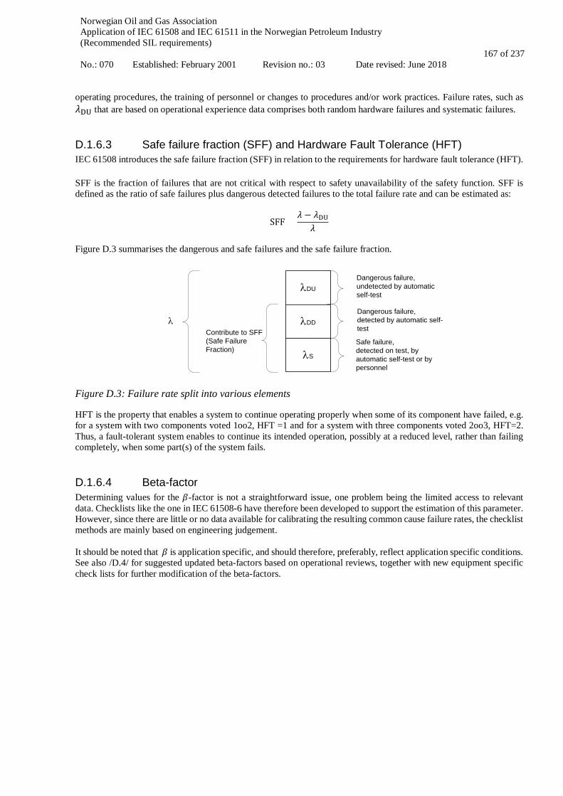
Norwegian Oil and Gas Association Application of IEC 61508 and IEC 61511 in the Norwegian Petroleum Industry (Recommended SIL requirements) No.: 070 Established: February 2001 Revision no.: 03 Date revised: June 2018
167 of 237
operating procedures, the training of personnel or changes to procedures and/or work practices. Failure rates, such as 𝜆𝜆DU that are based on operational experience data comprises both random hardware failures and systematic failures.
D.1.6.3 Safe failure fraction (SFF) and Hardware Fault Tolerance (HFT) IEC 61508 introduces the safe failure fraction (SFF) in relation to the requirements for hardware fault tolerance (HFT). SFF is the fraction of failures that are not critical with respect to safety unavailability of the safety function. SFF is defined as the ratio of safe failures plus dangerous detected failures to the total failure rate and can be estimated as:
SFF =𝜆𝜆 − 𝜆𝜆DU
𝜆𝜆 Figure D.3 summarises the dangerous and safe failures and the safe failure fraction.
Figure D.3: Failure rate split into various elements
HFT is the property that enables a system to continue operating properly when some of its component have failed, e.g. for a system with two components voted 1oo2, HFT =1 and for a system with three components voted 2oo3, HFT=2. Thus, a fault-tolerant system enables to continue its intended operation, possibly at a reduced level, rather than failing completely, when some part(s) of the system fails.
D.1.6.4 Beta-factor Determining values for the 𝛽𝛽-factor is not a straightforward issue, one problem being the limited access to relevant data. Checklists like the one in IEC 61508-6 have therefore been developed to support the estimation of this parameter. However, since there are little or no data available for calibrating the resulting common cause failure rates, the checklist methods are mainly based on engineering judgement. It should be noted that 𝛽𝛽 is application specific, and should therefore, preferably, reflect application specific conditions. See also /D.4/ for suggested updated beta-factors based on operational reviews, together with new equipment specific check lists for further modification of the beta-factors.
λDU
λDDλ
Dangerous failure, undetected by automatic self-test
Safe failure,detected on test, by automatic self-test or by personnel
Contribute to SFF (Safe FailureFraction)
Dangerous failure, detected by automatic self-test
λS
Norwegian Oil and Gas Association Application of IEC 61508 and IEC 61511 in the Norwegian Petroleum Industry (Recommended SIL requirements) No.: 070 Established: February 2001 Revision no.: 03 Date revised: June 2018
168 of 237
D.2 Probability of failure per hour (PFH) To measure loss of safety, the standards use probability of failure on demand (PFD) for low demand SISs and probability of failure per hour (PFH) for high demand / continuous operating SISs. IEC 61508 makes a distinction between low demand systems and high demand (or continuously operating) systems. A low demand system is a system that operates only upon a demand, and where the frequency of demands is no greater than one per year. Typical examples are a process shutdown system (PSD), a high integrity pressure protection system (HIPPS) or an emergency shutdown system (ESD). A high demand or continuous mode system is a system that experiences frequent (more than one) demand per year or operates more or less continuously. If operating continuously it can be seen more as a control system which shall prevent the process or equipment it controls from exceeding certain bounds. Typical examples of such systems will be a dynamic positioning system or a ballast system. For low demand systems, IEC 61508 applies the PFD as the measure for loss of safety. For high demand systems the IEC 61508 standard applies the PFH. This is the expected number of dangerous component or system failure(s) per hour. Thus, for a single component:
PFH1oo1 = 𝜆𝜆DU. In general, for a 1oo𝑁𝑁 configuration of 𝑁𝑁 identical components, failing independently, (i.e., not considering common cause failures) we have:
PFH1oo𝑁𝑁 ≈ (𝜆𝜆DU ⋅ 𝜏𝜏)𝑁𝑁/𝜏𝜏 ; for 𝑁𝑁 = 1, 2, 3, … ; independent failures only
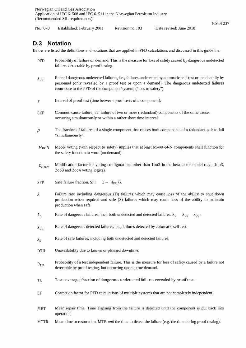
Norwegian Oil and Gas Association Application of IEC 61508 and IEC 61511 in the Norwegian Petroleum Industry (Recommended SIL requirements) No.: 070 Established: February 2001 Revision no.: 03 Date revised: June 2018
169 of 237
D.3 Notation Below are listed the definitions and notations that are applied in PFD calculations and discussed in this guideline.
PFD Probability of failure on demand. This is the measure for loss of safety caused by dangerous undetected failures detectable by proof testing.
𝜆𝜆DU Rate of dangerous undetected failures, i.e., failures undetected by automatic self-test or incidentally by personnel (only revealed by a proof test or upon a demand). The dangerous undetected failures contribute to the PFD of the component/system; ("loss of safety").
τ Interval of proof test (time between proof tests of a component).
CCF Common cause failure, i.e. failure of two or more (redundant) components of the same cause, occurring simultaneously or within a rather short time interval.
β The fraction of failures of a single component that causes both components of a redundant pair to fail “simultaneously”.
𝑀𝑀oo𝑁𝑁 MooN voting (with respect to safety) implies that at least M-out-of-N components shall function for the safety function to work (on demand).
C𝑀𝑀oo𝑁𝑁 Modification factor for voting configurations other than 1oo2 in the beta-factor model (e.g., 1oo3, 2oo3 and 2oo4 voting logics).
SFF Safe failure fraction. SFF = 1 − (𝜆𝜆DU/𝜆𝜆)
𝜆𝜆 Failure rate including dangerous (D) failures which may cause loss of the ability to shut down production when required and safe (S) failures which may cause loss of the ability to maintain production when safe.
𝜆𝜆D Rate of dangerous failures, incl. both undetected and detected failures. 𝜆𝜆D = 𝜆𝜆DU + 𝜆𝜆DD.
𝜆𝜆DD Rate of dangerous detected failures, i.e., failures detected by automatic self-test.
𝜆𝜆S Rate of safe failures, including both undetected and detected failures.
DTU Unavailability due to known or planned downtime.
PTIF Probability of a test independent failure. This is the measure for loss of safety caused by a failure not detectable by proof testing, but occurring upon a true demand.
TC Test coverage; fraction of dangerous undetected failures revealed by proof test.
CF Correction factor for PFD calculations of multiple systems that are not completely independent.
MRT Mean repair time. Time elapsing from the failure is detected until the component is put back into operation.
MTTR Mean time to restoration. MTR and the time to detect the failure (e.g. the time during proof testing).

Norwegian Oil and Gas Association Application of IEC 61508 and IEC 61511 in the Norwegian Petroleum Industry (Recommended SIL requirements) No.: 070 Established: February 2001 Revision no.: 03 Date revised: June 2018
170 of 237
PFH Probability of failure per hour. This is the average frequency of failure per hour of a component or system.

Norwegian Oil and Gas Association Application of IEC 61508 and IEC 61511 in the Norwegian Petroleum Industry (Recommended SIL requirements) No.: 070 Established: February 2001 Revision no.: 03 Date revised: June 2018
171 of 237
D.4 References /D.1/ S. Hauge, T. Kråkenes, P. Hokstad, S. Håbrekke and H. Jin: Reliability Prediction Method for Safety
Instrumented Systems – PDS Method Handbook 2013 Edition, SINTEF report A24442, ISBN 978-82-536-1333-8
/D.2/ S. Håbrekke, S. Hauge and T. Onshus: Reliability Data for Safety Instrumented Systems – PDS Data Handbook
2013 Edition, SINTEF Report A24443, ISBN 978-82-536-1334-5 /D.3/ S. Hauge, S. Håbrekke and M.A. Lundteigen: Reliability Prediction Method for Safety Instrumented Systems
– PDS Example Collection 2010 Edition, SINTEF report F15574 /D.4/ S. Hauge, Å.S. Hoem, P. Hokstad, S. Håbrekke and M.A. Lundteigen – Common Cause Failures in Safety
Instrumented Systems. Beta-factors and equipment specific checklists based on operational experience, SINTEF report A26922
Norwegian Oil and Gas Association Application of IEC 61508 and IEC 61511 in the Norwegian Petroleum Industry (Recommended SIL requirements) No.: 070 Established: February 2001 Revision no.: 03 Date revised: June 2018
172 of 237
APPLICATION OF IEC 61508 AND IEC 61511
IN THE NORWEGIAN PETROLEUM INDUSTRY
(Recommended SIL requirements)
Appendix E
LIFECYCLE PHASES, ACTIVITIES AND DOCUMENTATION

Norwegian Oil and Gas Association Application of IEC 61508 and IEC 61511 in the Norwegian Petroleum Industry (Recommended SIL requirements) No.: 070 Established: February 2001 Revision no.: 03 Date revised: June 2018
173 of 237
CONTENT
E.1 SRS STRUCTURE AND CONTENT ...................................................................................................... 174
E.1.1 SAFETY REQUIREMENT SPECIFICATION TEMPLATE ...................................................................................... 181
E.2 APPLICATION PROGRAM SAFETY REQUIREMENTS – STRUCTURE AND CONTENT .......... 184
E.3 SAFETY ANALYSIS REPORT (SAR) – STRUCTURE AND CONTENT ........................................... 200
E.4 SIL COMPLIANCE REPORT – STRUCTURE AND CONTENT ........................................................ 204
E.5 FUNCTIONAL SAFETY MANAGEMENT PLAN (FSMP) – STRUCTURE AND CONTENT ......... 206 E.5.1 FUNCTIONAL SAFETY MANAGEMENT PLAN (FSMP) ..................................................................................... 206 E.5.2 SAFETY PLANNING INFORMATION – EXAMPLE FOR SAS SUPPLIER ................................................................ 209
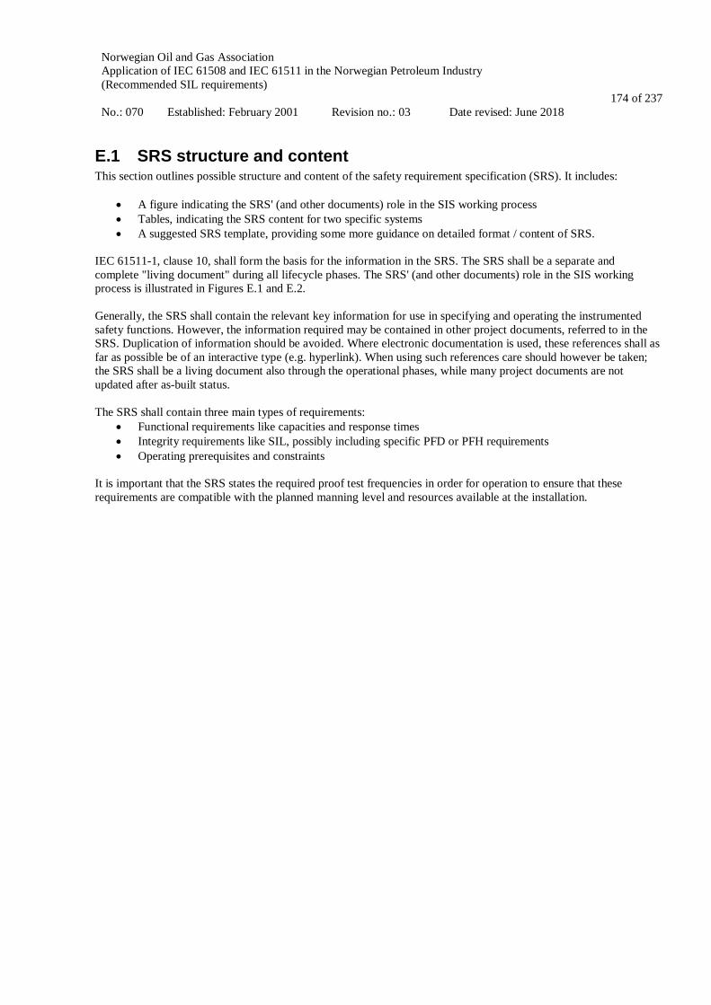
Norwegian Oil and Gas Association Application of IEC 61508 and IEC 61511 in the Norwegian Petroleum Industry (Recommended SIL requirements) No.: 070 Established: February 2001 Revision no.: 03 Date revised: June 2018
174 of 237
E.1 SRS structure and content This section outlines possible structure and content of the safety requirement specification (SRS). It includes:
• A figure indicating the SRS' (and other documents) role in the SIS working process • Tables, indicating the SRS content for two specific systems • A suggested SRS template, providing some more guidance on detailed format / content of SRS.
IEC 61511-1, clause 10, shall form the basis for the information in the SRS. The SRS shall be a separate and complete "living document" during all lifecycle phases. The SRS' (and other documents) role in the SIS working process is illustrated in Figures E.1 and E.2. Generally, the SRS shall contain the relevant key information for use in specifying and operating the instrumented safety functions. However, the information required may be contained in other project documents, referred to in the SRS. Duplication of information should be avoided. Where electronic documentation is used, these references shall as far as possible be of an interactive type (e.g. hyperlink). When using such references care should however be taken; the SRS shall be a living document also through the operational phases, while many project documents are not updated after as-built status. The SRS shall contain three main types of requirements:
• Functional requirements like capacities and response times • Integrity requirements like SIL, possibly including specific PFD or PFH requirements • Operating prerequisites and constraints
It is important that the SRS states the required proof test frequencies in order for operation to ensure that these requirements are compatible with the planned manning level and resources available at the installation.

Norwegian Oil and Gas Association Application of IEC 61508 and IEC 61511 in the Norwegian Petroleum Industry (Recommended SIL requirements) No.: 070 Established: February 2001 Revision no.: 03 Date revised: June 2018
175 of 237
Notes Activity Time axis Documentation Interface Projectphase
Requirements given in Contract & Regulations
Test intervals & acceptance criteria from
Client/Operator (or other relevant sources
such as NOG 070, previous similar projects,
etc.)
Overall lifecycle requirements integrated in
NOG 070
NOG 070 requirements from ”minimum SIL table” for ”standard SIFs”. SIL requirements for similar
SIFs can also be developed based on this
table.
All NOG 070 established SIL are reviewed to ensure applicability
Perform reliability calculations for SIFs using
generic data from data dossier
SIL input to packages (inquiry, BCM, package
specification)
SARs are reviewed & commented by project and
updated by vendors if required.
Interface vs. other project documentation (functional
spec’s, FAT and operational procedures, etc.).
Scope definition. Define responsibilities &
organisation. Define acceptance criteria.
Identify EUC & SIS’s/SIFs to be SIL evaluated
Hazard identification, HAZOP & risk analysis
Establish overall safety requirements
Allocate SIL to SIFs based on NO&G’s GL 070
For identified EUC & SIFs not covered by NOG 070
”min. SIL table”: à Allocate SIL based on
NOG 070 deviation method
Operation & maintenance philosofies & SIL
operational strategy
Establish detailed requirements for SIS
realisation
SIS realisation
Overall safety validation planning
Operator
FEED ”Functional Safety Management
Plan”
Operator
FEED ”SIL Id. & Allocation Report”
Operator
FEED
”SRS – Main Document”(1st. rev.)
Vendors
FEED ”SRS”
DETAIL
ENGINEERING
&
PROC.
&
CONSTRUC.
”System SRS’s”(1st. rev.)
”SARs”(1st. rev).
Input to operation & maintenance
planOperator
Vendors”SARs”(Final rev.)
”SRS – Main Document”(2nd. rev.)
”System SRS’s”(2nd. rev.)
To Commisoning & Operational phase
Verification Validation FSA X Ref. lifecycle in IEC 61508 Ref. lifecycle in IEC 61511X
1
2
2
3
4
5
5
6
9
7 6
13
9
5
10
65
10
9
4
3
1
2
2
”FSA light”
FEED ”SAR – Supplier
Requirements”
EPC ”SAR Requirements to
Vendors”
EPC ”SIL Id. & Allocation
Report”
EPC ”SIL Working Method
Report”
SRS’s transferred to MC & commissioning
Figure E.1 SIS working process for implementation of SIL in FEED & Detail Engineering / EPC phases.
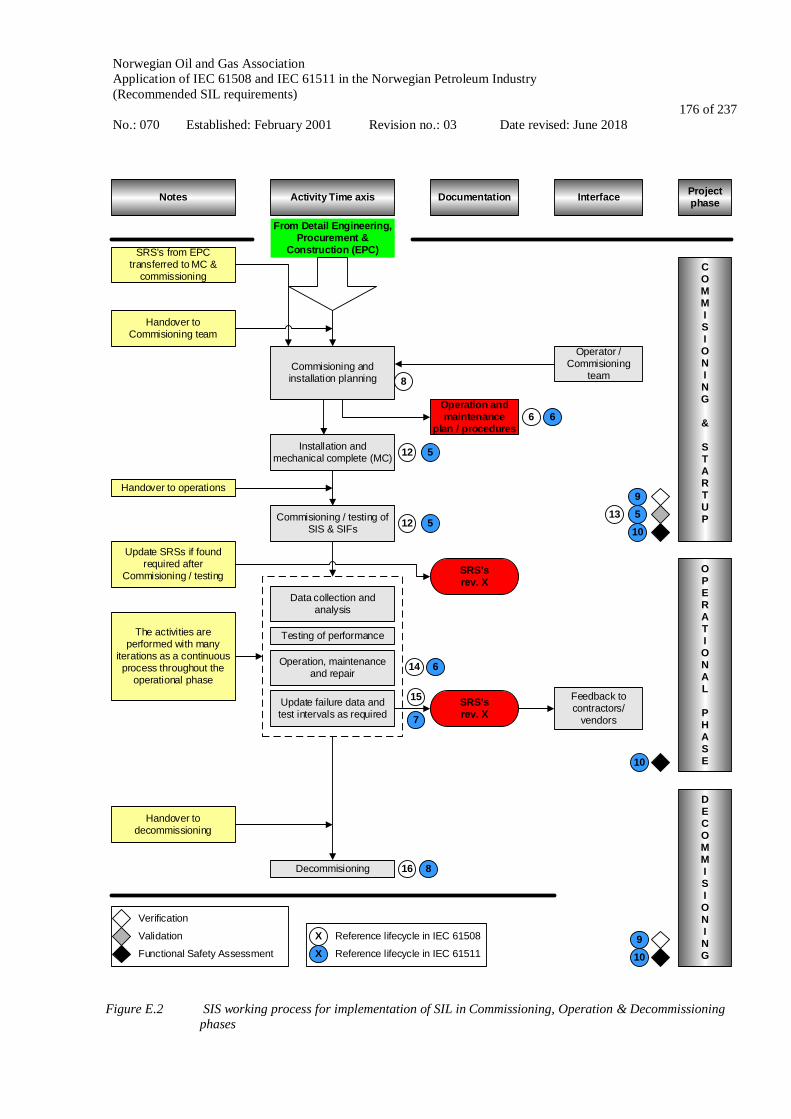
Norwegian Oil and Gas Association Application of IEC 61508 and IEC 61511 in the Norwegian Petroleum Industry (Recommended SIL requirements) No.: 070 Established: February 2001 Revision no.: 03 Date revised: June 2018
176 of 237
Notes Activity Time axis Documentation Interface Projectphase
Handover to Commisioning team
Commisioning and installation planning
COMMISIONING
&
STARTUP
16 8
From Detail Engineering, Procurement &
Construction (EPC)
Operation and maintenance
plan / proceduresInstallation and
mechanical complete (MC)
Commisioning / testing of SIS & SIFs
Handover to operations
Data collection and analysis
Testing of performance
Operation, maintenance and repair
Update failure data and test intervals as required
The activities are performed with many
iterations as a continuous process throughout the
operational phase
SRS’srev. X
Feedback to contractors/
vendors
Decommisioning
Handover to decommissioning
OPERATIONAL
PHASE
DECOMMISIONING
Verification
Validation
Functional Safety Assessment
X Reference lifecycle in IEC 61508
Reference lifecycle in IEC 61511X
8
6 6
12 51059
13
14
12 5
6
15
7
10
109
SRS’s from EPC transferred to MC &
commissioning
Operator / Commisioning
team
SRS’srev. X
Update SRSs if found required after
Commisioning / testing
Figure E.2 SIS working process for implementation of SIL in Commissioning, Operation & Decommissioning
phases

Norwegian Oil and Gas Association Application of IEC 61508 and IEC 61511 in the Norwegian Petroleum Industry (Recommended SIL requirements) No.: 070 Established: February 2001 Revision no.: 03 Date revised: June 2018
177 of 237
Tables with suggested content for the SRS based on IEC 61511-1, clause 10.3, have been made and are shown as examples below. It should be noted that all elements listed in IEC 61511 are not relevant for all types of SIS. Further, note that much of the required content of the SRS will not be available during early project phases. Therefore, the relevant SRS revision number (reflecting chronological order or events) are based on the time/phase at which a requirement should be included. The two example tables shown below are based on a document structure where one SRS is produced per system. It should be noted that other SRS structures will be possible, e.g. one common SRS for all the defined safety functions. Example table E.1 shows a proposed SRS list of content for the PSD system. The PSD system will connect to most of the plant processes, which are documented in other design documents (e.g. ISO 10418, SAT tables, HAZOP). PSD systems for other than hydrocarbon systems are not covered by ISO 10418. The design and supply of these systems will normally be specified in a Functional Specification for the unit or system. Example table E.2 indicates an SRS list of content for the F&G and the ESD system. Requirements to these two global safety systems will be defined in safety specifications. These systems will also have safety interfaces to other systems (shut down of electrical systems, HVAC systems, etc.). The instrumented safety function shall be described completely in the SRS for the F&G and ESD system, while equipment data for the interfaced systems shall be included in the relevant system Functional Specification. As discussed above, some of the required content of the SRS cannot be given at early phases of the project execution. Hence, the relevant SRS revision number when a requirement should be included has been indicated. Some requirements should be established before the first SRS is produced, and in such case, the relevant project phase is referred. The two example tables given below suggest where the different information shall be found. It should be noted that these are only suggestions as the project may select other documentation structures.

Norwegian Oil and Gas Association Application of IEC 61508 and IEC 61511 in the Norwegian Petroleum Industry (Recommended SIL requirements) No.: 070 Established: February 2001 Revision no.: 03 Date revised: June 2018
178 of 237
Table E.1 List of content for SRS for PSD system.
ID Reference, IEC 61511, cl. 10.3 PSD for
hydrocarbon systems
PSD for other process systems
SRS rev. no
a) Description of all the necessary instrumented functions to achieve the required functional safety
ISO 10418 SAT
Functional specification FEED SRS
b) A list of the plant input and output devices related to each SIF which is clearly identified by the plant means of equipment identification (e.g., field tag list);
c) Requirements to identify and take account of common cause failures SRS Functional
specification SRS rev. 1
d) Definition of the safe state of the process for each identified safety instrumented function SRS SRS FEED SRS
e) Definition of any individually safe process states which, when occurring concurrently, create a separate hazard
ISO 10418 SAT
Functional specification SRS rev. 2
f) Assumed sources of demand and demand rate of the safety instrumented function SRS SRS FEED SRS
g) Requirement of proof test intervals SRS SRS FEED SRS h) Requirements related to proof test implementation
i) Response time requirement for the SIS to bring the process to a safe state SRS SRS SRS rev. 1
j) Safety integrity level and mode of operation (demand /continuous) for each SIF SRS SRS FEED SRS
k) Description of SIS process measurements and their trip points SRS SRS SRS rev. 2 l) Description of SIF process output actions and the criteria for
successful operation, e.g. leakage rate for valves. ISO 10418
SAT Functional
specification SRS rev. 2
m) Functional relationship between process inputs and outputs, including logic, mathematical functions
PI&Ds/SCD and C&E
PI&D/SCD and C&E SRS rev. 1
n) Requirements for manual shutdown SRS SRS SRS rev. 1 o) Requirement related to energize or de-energize to trip SRS SRS SRS rev. 1 p) Requirements for resetting each SIF after a shutdown (e.g.,
requirements for manual, semi-automatic, or automatic final element resets after trips);
SRS SRS SRS rev. 1
q) Maximum allowable spurious trip rate for each SIF; SRS SRS SRS rev. 1 r) Failure modes and desired response of the SIS SRS SRS SRS rev. 2 s) Any specific requirements related to the procedure for starting
up and restarting the SIS SRS SRS SRS rev. 1
t) All interfaces between the SIS and any other system SRS SRS SRS rev. 1 u) Description of the modes of operation of the plant and
requirements relating to SIF operation within each mode; Functional
specification Functional
specification SRS rev. 2
v) The application program safety requirements Ref 61511, section 12.2.2
Ref 61511, section 12.2.2 SRS rev. 1
w) Requirements for overrides/ inhibits/ bypasses including how they will be cleared SRS SRS SRS rev. 1
x) Specification of any action necessary to achieve a safe state in the event of faults being detected by the SIS. Any such action shall be determined taking account of all relevant human factors
SRS SRS SRS rev. 1
y) The mean repair time which is feasible for the SIS, taking into account the travel time, location, spares holding, service contracts, environmental constraints;
SRS SRS SRS rev. 2
z) Dangerous combinations of output states of the SIS shall be addressed SRS SRS SRS rev. 2

Norwegian Oil and Gas Association Application of IEC 61508 and IEC 61511 in the Norwegian Petroleum Industry (Recommended SIL requirements) No.: 070 Established: February 2001 Revision no.: 03 Date revised: June 2018
179 of 237
ID Reference, IEC 61511, cl. 10.3 PSD for
hydrocarbon systems
PSD for other process systems
SRS rev. no
aa) The extremes of all environmental conditions that are likely to be encountered by the SIS shall be identified. This may require consideration of the following; temperature, humidity, contaminants, grounding, electromagnetic interference, etc. (see IEC 61511, cl. 10.3)
SRS SRS SRS rev. 1
bb) Identification to normal and abnormal modes for both the plant as whole and individual plant operational procedures (for example, equipment maintenance, sensor calibration and/or repair)). Additional safety instrumented functions may be required to support these modes of operation.
Functional specification
Functional specification FEED SRS
cc) Definition of the requirement for any safety instrumented function necessary to survive a major accident event, for example, time required for a valve to remain operational in the event of a fire.
Safety specification
Safety specification SRS rev. 1
Table E.2 List of content for SRS for F&G and ESD systems.
ID Reference, IEC 61511, cl. 10.3 F&G system ESD system SRS rev. no / Lifecycle
phase a) Description of all the necessary instrumented functions to
achieve the required functional safety Safety
specification Safety
specification FEED SRS
b) A list of the plant input and output devices related to each SIF which is clearly identified by the plant means of equipment identification (e.g., field tag list)
c) Requirements to identify and take account of common cause failures SRS SRS SRS rev. 1
d) Definition of the safe state of the process for each identified safety instrumented function SRS SRS FEED SRS
e) Definition of any individually safe process states which, when occurring concurrently, create a separate hazard SRS SRS SRS rev. 2
f) Assumed sources of demand and demand rate of the safety instrumented function SRS SRS FEED SRS
g) Requirement of proof test intervals SRS SRS FEED SRS h) Requirements related to proof test implementation
i) Response time requirement for the SIS to bring the process to a safe state SRS SRS SRS rev. 1
j) Safety integrity level and mode of operation (demand /continuous) for each SIF SRS SRS FEED SRS
k) Description of SIS process measurements and their trip points SRS SRS SRS rev. 2 l) Description of SIF process output actions and the criteria for
successful operation, e.g. leakage rate for valves. Functional
specification Functional
specification SRS rev. 2
m) Functional relationship between process inputs and outputs, including logic, mathematical functions
Fire protect. Data sheets
C&E SRS rev. 1
n) Requirements for manual shutdown SRS SRS SRS rev. 1 o) Requirement related to energize or de-energize to trip SRS SRS SRS rev. 1 p) Requirements for resetting each SIF after a shutdown (e.g.,
requirements for manual, semi-automatic, or automatic final element resets after trips);
SRS SRS SRS rev. 1
q) Maximum allowable spurious trip rate for each SIF; SRS SRS SRS rev. 1 r) Failure modes and desired response of the SIS SRS SRS SRS rev. 2 s) Any specific requirements related to the procedure for starting
up and restarting the SIS SRS SRS SRS rev. 1
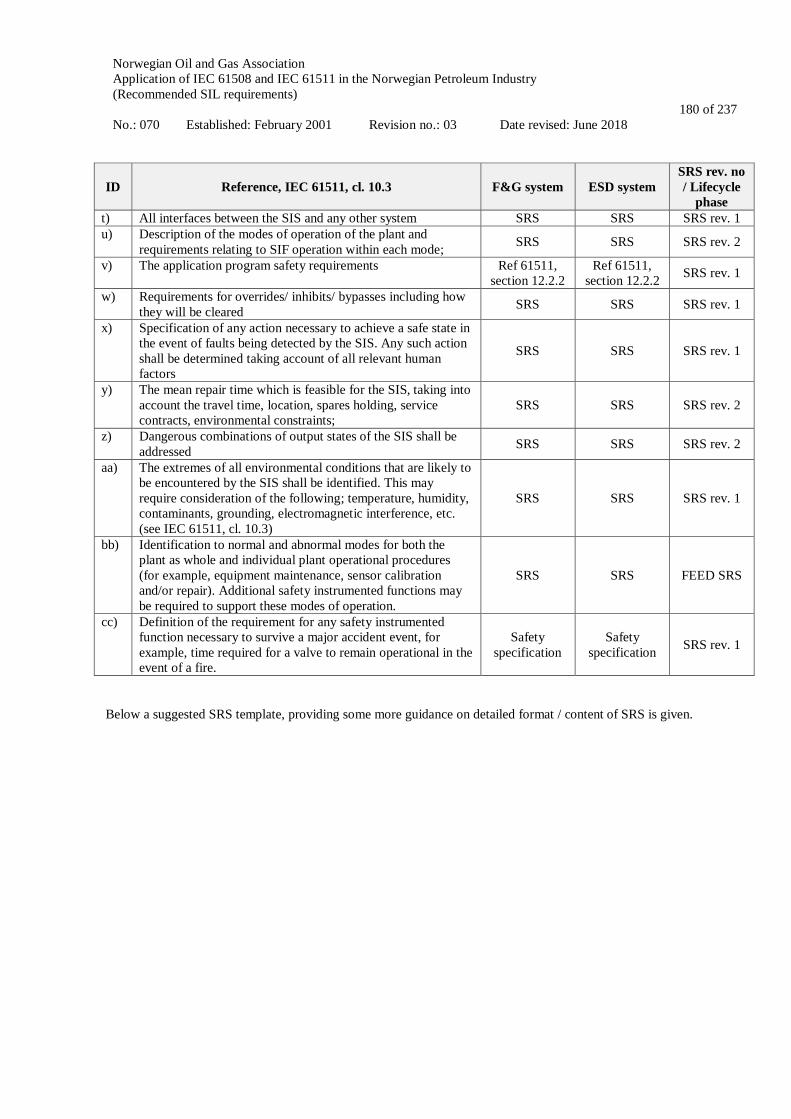
Norwegian Oil and Gas Association Application of IEC 61508 and IEC 61511 in the Norwegian Petroleum Industry (Recommended SIL requirements) No.: 070 Established: February 2001 Revision no.: 03 Date revised: June 2018
180 of 237
ID Reference, IEC 61511, cl. 10.3 F&G system ESD system SRS rev. no / Lifecycle
phase t) All interfaces between the SIS and any other system SRS SRS SRS rev. 1 u) Description of the modes of operation of the plant and
requirements relating to SIF operation within each mode; SRS SRS SRS rev. 2
v) The application program safety requirements Ref 61511, section 12.2.2
Ref 61511, section 12.2.2 SRS rev. 1
w) Requirements for overrides/ inhibits/ bypasses including how they will be cleared SRS SRS SRS rev. 1
x) Specification of any action necessary to achieve a safe state in the event of faults being detected by the SIS. Any such action shall be determined taking account of all relevant human factors
SRS SRS SRS rev. 1
y) The mean repair time which is feasible for the SIS, taking into account the travel time, location, spares holding, service contracts, environmental constraints;
SRS SRS SRS rev. 2
z) Dangerous combinations of output states of the SIS shall be addressed SRS SRS SRS rev. 2
aa) The extremes of all environmental conditions that are likely to be encountered by the SIS shall be identified. This may require consideration of the following; temperature, humidity, contaminants, grounding, electromagnetic interference, etc. (see IEC 61511, cl. 10.3)
SRS SRS SRS rev. 1
bb) Identification to normal and abnormal modes for both the plant as whole and individual plant operational procedures (for example, equipment maintenance, sensor calibration and/or repair). Additional safety instrumented functions may be required to support these modes of operation.
SRS SRS FEED SRS
cc) Definition of the requirement for any safety instrumented function necessary to survive a major accident event, for example, time required for a valve to remain operational in the event of a fire.
Safety specification
Safety specification SRS rev. 1
Below a suggested SRS template, providing some more guidance on detailed format / content of SRS is given.
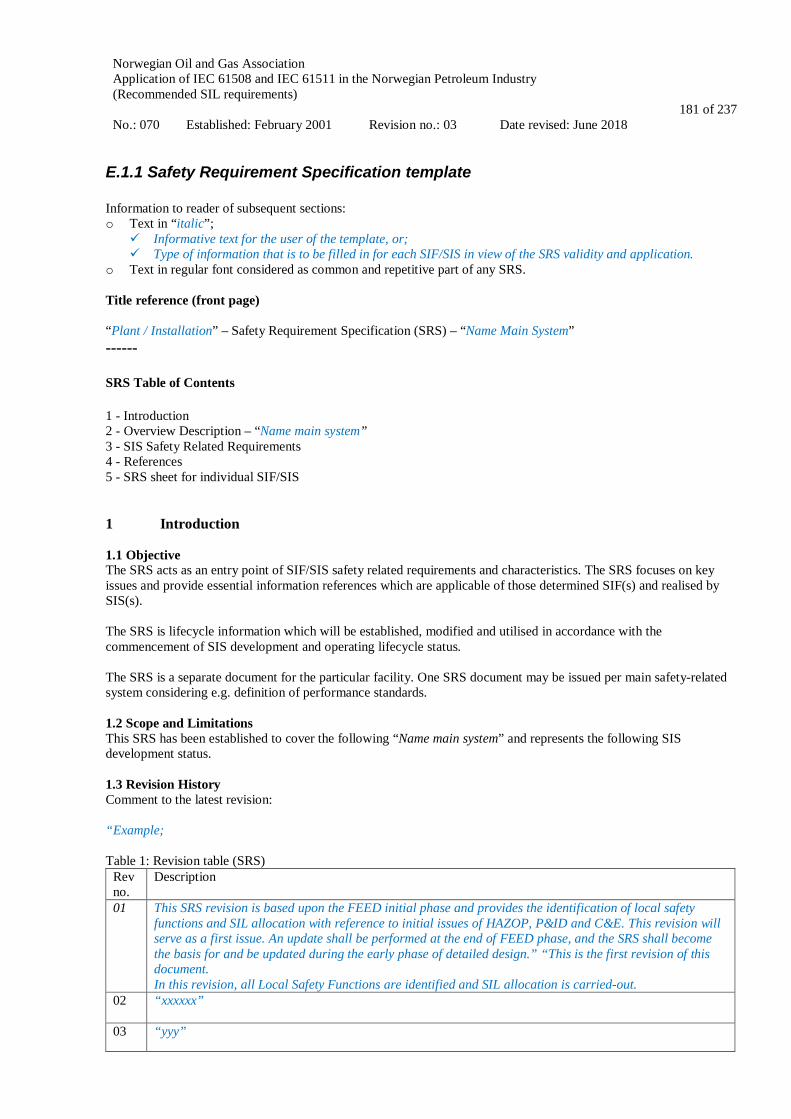
Norwegian Oil and Gas Association Application of IEC 61508 and IEC 61511 in the Norwegian Petroleum Industry (Recommended SIL requirements) No.: 070 Established: February 2001 Revision no.: 03 Date revised: June 2018
181 of 237
E.1.1 Safety Requirement Specification template Information to reader of subsequent sections: o Text in “italic”;
Informative text for the user of the template, or; Type of information that is to be filled in for each SIF/SIS in view of the SRS validity and application.
o Text in regular font considered as common and repetitive part of any SRS. Title reference (front page) “Plant / Installation” – Safety Requirement Specification (SRS) – “Name Main System” ------ SRS Table of Contents 1 - Introduction 2 - Overview Description – “Name main system” 3 - SIS Safety Related Requirements 4 - References 5 - SRS sheet for individual SIF/SIS 1 Introduction 1.1 Objective The SRS acts as an entry point of SIF/SIS safety related requirements and characteristics. The SRS focuses on key issues and provide essential information references which are applicable of those determined SIF(s) and realised by SIS(s). The SRS is lifecycle information which will be established, modified and utilised in accordance with the commencement of SIS development and operating lifecycle status. The SRS is a separate document for the particular facility. One SRS document may be issued per main safety-related system considering e.g. definition of performance standards. 1.2 Scope and Limitations This SRS has been established to cover the following “Name main system” and represents the following SIS development status. 1.3 Revision History Comment to the latest revision: “Example; Table 1: Revision table (SRS)
Rev no.
Description
01 This SRS revision is based upon the FEED initial phase and provides the identification of local safety functions and SIL allocation with reference to initial issues of HAZOP, P&ID and C&E. This revision will serve as a first issue. An update shall be performed at the end of FEED phase, and the SRS shall become the basis for and be updated during the early phase of detailed design.” “This is the first revision of this document. In this revision, all Local Safety Functions are identified and SIL allocation is carried-out.
02 “xxxxxx”
03 “yyy”

Norwegian Oil and Gas Association Application of IEC 61508 and IEC 61511 in the Norwegian Petroleum Industry (Recommended SIL requirements) No.: 070 Established: February 2001 Revision no.: 03 Date revised: June 2018
182 of 237
1.4 Abbreviations “List of relevant and frequently used abbreviations (note: references to relevant IEC 61511 abbreviations may be used)”. 1.5 Main SIF/SIS references Table 2: Key SIF/SIS reference list (SRS)
Doc., name Doc. number
“National / regional authority requirements”
Functional safety management plan (FSM plan) also including guidance for equipment manufacturers and vendors (generally applicable for the whole plant/installation) “xxxxxx”
SIL allocation report “xxxxxx”
Safety requirement specification(s) This document
Compliance report incorporating calculation and data dossier (CDD) “xxxxxx”
Further details of governance documentation and SIS references will be given in “chapter 4” 2 Overview Description – “Name Main System” 2.1 Purpose of “Name Main System” “Example: The PSD system is the primary protection according to ISO 10418. The PSD system shall detect abnormal process conditions and initiate automatic actions in order to prevent demand on the secondary process protection (e.g. PSV relief valves), and to prevent critical damage of process segments resulting in e.g. an uncontrolled release of hydrocarbons. It shall automatically shut down completely or partly the production facilities when hazards to life, health, environment and equipment may occur”. 2.2 Interfaces SIS / SIF shall interface with the following systems as minimum: “Example: • System number, name, purpose • System number, name, purpose • Etc.” “An overall sketch illustrating interconnections and dependencies between different main systems should be made and also including PCS or local control units where relevant for the SIS functional behaviour. For detailed descriptions references to other discipline documentation are necessary, e.g., SAS Functional Design Specification”. 3 SIS Safety Related Requirements 3.1 References of Safety Requirement Specification content References are made to IEC 61511-1, cl. 10.3.1. For each of the points a) – cc) a reference to where the information can be found should be given. Examples of such references will include (see Table E.1 and E.2 in this Appendix)
• ISO 10418 SAT

Norwegian Oil and Gas Association Application of IEC 61508 and IEC 61511 in the Norwegian Petroleum Industry (Recommended SIL requirements) No.: 070 Established: February 2001 Revision no.: 03 Date revised: June 2018
183 of 237
• Section in this SRS • P&ID • C&E • FSMP • Etc.
Information that is common to most functions should be given here instead of repeating it for each function in section 5. 3.2 Other risk reducing measures “Examples: For the different safety functions there will be different barriers which are not dependent upon electronic, electric or programmable electronic technology. For high pressure scenarios, PSVs will be installed according to ISO 10418. All piping and vessels will, due to conservative design and conformance to ISO and ASME codes, have extra capacity to withstand pressure higher than the design pressures for shorter or longer time periods. For detection of low levels due to a leak in the processing system, there will be gas detectors installed in the process, wellhead and riser areas and in the HVAC intakes for the utility/LQ areas. Drip trays will be installed under all large pieces of process equipment where any maintenance will take place. Fire and blast barriers will be installed between the riser/wellhead and process areas and between the process and utility areas. There will be extensive fire and gas detection and fire water coverage throughout the process, wellhead and riser balcony areas. All critical structure will be evaluated for fire resistance and will be fire proofed as required by analyses. Critical cabling will be protected to withstand design accidental loads for a given time period.” 3.3 Software requirements Herein a short/abstract description of the main requirements for embedded software and application program can be included. Detailed application program safety requirements (see example in Appendix E.2 in this document) are given in:
• Application program safety requirements specification (separate document or as part of SRS) • Detailed functional design specification • Other (dependent on plan documentation structure)
4 References Include list of relevant references, including both governing documents and plant/installation specific documents. 5 SRS sheet for specific SIF Aspects not general to several SIFs may be listed in individual sheets for each SIF in accordance with the SIF determination and SIL allocation report. In such case a list of all identified SIFs should be given. A unique ID number should be given for each SIF for ease of referencing.
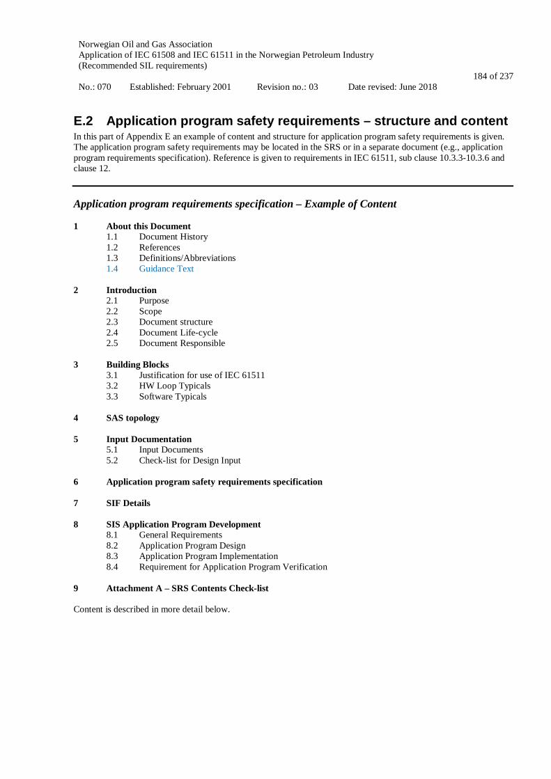
Norwegian Oil and Gas Association Application of IEC 61508 and IEC 61511 in the Norwegian Petroleum Industry (Recommended SIL requirements) No.: 070 Established: February 2001 Revision no.: 03 Date revised: June 2018
184 of 237
E.2 Application program safety requirements – structure and content In this part of Appendix E an example of content and structure for application program safety requirements is given. The application program safety requirements may be located in the SRS or in a separate document (e.g., application program requirements specification). Reference is given to requirements in IEC 61511, sub clause 10.3.3-10.3.6 and clause 12. Application program requirements specification – Example of Content 1 About this Document
1.1 Document History 1.2 References 1.3 Definitions/Abbreviations 1.4 Guidance Text
2 Introduction
2.1 Purpose 2.2 Scope 2.3 Document structure 2.4 Document Life-cycle 2.5 Document Responsible
3 Building Blocks
3.1 Justification for use of IEC 61511 3.2 HW Loop Typicals 3.3 Software Typicals
4 SAS topology 5 Input Documentation
5.1 Input Documents 5.2 Check-list for Design Input
6 Application program safety requirements specification 7 SIF Details 8 SIS Application Program Development
8.1 General Requirements 8.2 Application Program Design 8.3 Application Program Implementation 8.4 Requirement for Application Program Verification
9 Attachment A – SRS Contents Check-list Content is described in more detail below.

Norwegian Oil and Gas Association Application of IEC 61508 and IEC 61511 in the Norwegian Petroleum Industry (Recommended SIL requirements) No.: 070 Established: February 2001 Revision no.: 03 Date revised: June 2018
185 of 237
1 About this Document 1.1 Document History Table 1: Document history
Revision Description of change
A This is the first issue
1.2 References The project shall update the table below with relevant installation/project references. Table 2: References
Ref Document number Description Rev.
[1]
[2]
[3] 1.3 Definitions/Abbreviations 1.3.1 Definitions Table 3: Definitions
Phrase to define: Definition:
1.3.2 Abbreviations Table 4: Abbreviations
Abbreviation: Explanation:
1.4 Guidance Text Blue guidance text is included in the chapters where the project shall fill in relevant installation text. Blue text can be deleted at the end.

Norwegian Oil and Gas Association Application of IEC 61508 and IEC 61511 in the Norwegian Petroleum Industry (Recommended SIL requirements) No.: 070 Established: February 2001 Revision no.: 03 Date revised: June 2018
186 of 237
2 Introduction 2.1 Purpose The purpose of this document is to identify the requirements of the Application Software for the Logic Solver part of the SIS necessary to implement all required SIFs consistent with the requirements put forward in the SRS. 2.2 Scope This document is an example of an internal vendor document to ensure compliance with IEC 61511-1 ed.2, chapter 10.3.2 and 12. This document should be adapted to each vendor and project. Main readers will be those developing the application program. To avoid duplicate information, link to specific parts in other relevant documents can be used. 2.3 Document structure The document is split into three parts.
• General • Compliance to chapter 10.3.2 (application program safety requirements) • Compliance to chapter 12 (SIS application program development )
2.3.1 General Chapter 3 gives a general description of how the application is designed and implemented by use of building blocks. Chapter 4 and 5 is project specific and shall be filled out by a competent project team member. 2.3.2 Compliance to IEC 61511-1, sub clause 10.3.2 Chapter 6 and 7 contains relevant compliance to sub clause 10.3.2. The objective of these chapters is to derive the application requirements and make sure that this is maintained by the application design. Table 5: IEC 61511-1, cl. 10.3.2 Application Program Safety Requirements
2.3.3 Compliance to IEC 61511-1, clause 12 Chapter 8 contains relevant compliance to clause 12 of IEC 61511-1. The objective of this chapter is to define the requirements for the development of the application program.
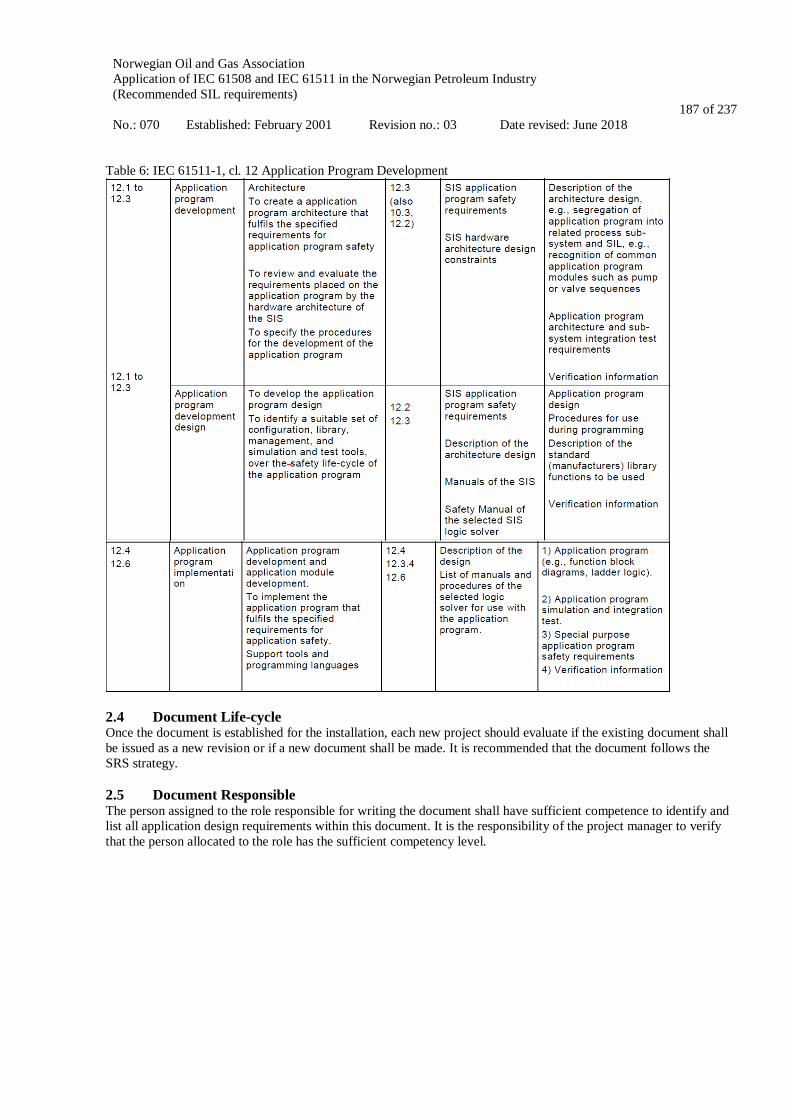
Norwegian Oil and Gas Association Application of IEC 61508 and IEC 61511 in the Norwegian Petroleum Industry (Recommended SIL requirements) No.: 070 Established: February 2001 Revision no.: 03 Date revised: June 2018
187 of 237
Table 6: IEC 61511-1, cl. 12 Application Program Development
2.4 Document Life-cycle Once the document is established for the installation, each new project should evaluate if the existing document shall be issued as a new revision or if a new document shall be made. It is recommended that the document follows the SRS strategy. 2.5 Document Responsible The person assigned to the role responsible for writing the document shall have sufficient competence to identify and list all application design requirements within this document. It is the responsibility of the project manager to verify that the person allocated to the role has the sufficient competency level.

Norwegian Oil and Gas Association Application of IEC 61508 and IEC 61511 in the Norwegian Petroleum Industry (Recommended SIL requirements) No.: 070 Established: February 2001 Revision no.: 03 Date revised: June 2018
188 of 237
3 Building Blocks This chapter is entirely SAS supplier specific and the template can probably contain most of the text required. 3.1 Justification for use of IEC 61511 In this chapter the project argue why they can use IEC 61511 and LVL (ref. figure 2 and 3 in IEC 61511-1.). 3.2 HW Loop Typicals The project shall update the table below to contain typicals used by the installation/project. The table can initially contain all typicals and the project can delete the ones not required. Table 7: HW loop typicals Typical I/O card Description Purpose
3.3 Software Typicals
The project shall update the table below to contain typicals used by the installation/project. The table can initially contain all typicals and the project can delete the ones not required. Table 8: Software typicals
Name Description
4 SAS topology The project shall include a short description of the installation/project SAS (topology), safety systems, number of nodes, inter-connections, communication to other nodes and third party equipment, operator interfaces, remote access etc. 5 Input Documentation Input documents shall be listed with document number, document title, revision and date. The most relevant documents are I/O list, SRS, CPI, SCD, C&E, Functional specification (FS) and data sheets for field equipment. Verification shall be done to assure that the SRS contains sufficient information for application programming to be carried out. 5.1 Input Documents The project shall update the table below with relevant input documentation used by the installation/project.

Norwegian Oil and Gas Association Application of IEC 61508 and IEC 61511 in the Norwegian Petroleum Industry (Recommended SIL requirements) No.: 070 Established: February 2001 Revision no.: 03 Date revised: June 2018
189 of 237
Table 9: Input documents
Document id Document title Revision Date
5.2 Check-list for Design Input A check-list, ref. chapter 9 (Attachment A) shall be filled out to secure that the quality and content of the SRS issued by the customer is sufficient to design and manufacture the SIS. There will be separate check-lists for ESD, F&G and PSD. In the absence of available information, any assumptions made against particular items shall be clearly stated in the ‘Comment’ column, and included as formal assumptions in the SAR. 6 Application program safety requirements specification The table below describes how each requirement to the application design in IEC-61511-1, sub clause 10.3.5 is complied to. The text in this chapter is general for all identified SIF’s. SIF specific requirements are identified in chapter 7. The project shall update the “Compliance” column in the table below with relevant installation/project text if other then template. The template should probably be more specific and put in references to relevant documents in the “compliance” column. Table 10: General SIF description
Requirements Compliance
-a SIFs Implemented See chapter 7
-b SIS subsystems properties and set-up
The system shall be set up to comply with requirements defined in governing documents, e.g. PSA Norway, NORSOK etc., standards and customer requirements, e.g. SRS, FS, Philosophy etc. The setup shall be in line with approved product architecture. Topology drawings and other relevant documents to be identified.
-c Program sequencing and time delays
Implementation of sequencing and time delays are done according to customer requirements and programming guidelines. Sequencing, e.g. shutdown of wells, blowdown etc. shall be identified, if any. Delays of initiation signals, outputs, diagnostics etc. shall be identified, if any.
-d Operator Interfaces
Implementation of operator interfaces are done according to customer requirements and programming guidelines. HMI, blocking, key switches, permissions (safety user), reset (how to reset device), alarming (incl. how to clear alarms, whether alarms need latching or not), CAAP interaction, SIF operation restrictions. Links can be made to relevant drawings and documentation.
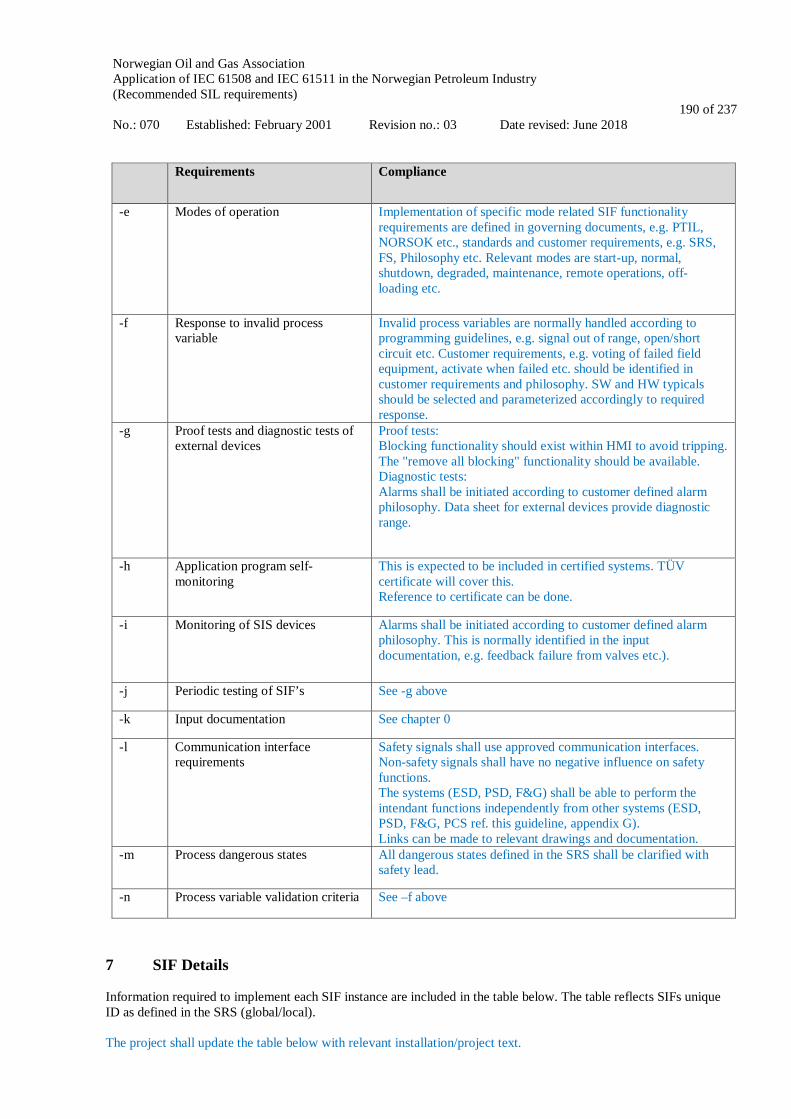
Norwegian Oil and Gas Association Application of IEC 61508 and IEC 61511 in the Norwegian Petroleum Industry (Recommended SIL requirements) No.: 070 Established: February 2001 Revision no.: 03 Date revised: June 2018
190 of 237
Requirements Compliance
-e Modes of operation Implementation of specific mode related SIF functionality requirements are defined in governing documents, e.g. PTIL, NORSOK etc., standards and customer requirements, e.g. SRS, FS, Philosophy etc. Relevant modes are start-up, normal, shutdown, degraded, maintenance, remote operations, off-loading etc.
-f Response to invalid process variable
Invalid process variables are normally handled according to programming guidelines, e.g. signal out of range, open/short circuit etc. Customer requirements, e.g. voting of failed field equipment, activate when failed etc. should be identified in customer requirements and philosophy. SW and HW typicals should be selected and parameterized accordingly to required response.
-g Proof tests and diagnostic tests of external devices
Proof tests: Blocking functionality should exist within HMI to avoid tripping. The "remove all blocking" functionality should be available. Diagnostic tests: Alarms shall be initiated according to customer defined alarm philosophy. Data sheet for external devices provide diagnostic range.
-h Application program self-monitoring
This is expected to be included in certified systems. TÜV certificate will cover this. Reference to certificate can be done.
-i Monitoring of SIS devices Alarms shall be initiated according to customer defined alarm philosophy. This is normally identified in the input documentation, e.g. feedback failure from valves etc.).
-j Periodic testing of SIF’s See -g above
-k Input documentation See chapter 0
-l Communication interface requirements
Safety signals shall use approved communication interfaces. Non-safety signals shall have no negative influence on safety functions. The systems (ESD, PSD, F&G) shall be able to perform the intendant functions independently from other systems (ESD, PSD, F&G, PCS ref. this guideline, appendix G). Links can be made to relevant drawings and documentation.
-m Process dangerous states All dangerous states defined in the SRS shall be clarified with safety lead.
-n Process variable validation criteria See –f above
7 SIF Details Information required to implement each SIF instance are included in the table below. The table reflects SIFs unique ID as defined in the SRS (global/local). The project shall update the table below with relevant installation/project text.

Norwegian Oil and Gas Association Application of IEC 61508 and IEC 61511 in the Norwegian Petroleum Industry (Recommended SIL requirements) No.: 070 Established: February 2001 Revision no.: 03 Date revised: June 2018
191 of 237
Table 11: SIF details
SIF SIL HW typical
SW typical Node Inter-node Blocking NE/NDE
Action to be taken on bad process variable
Start-up overrides Response time Reset
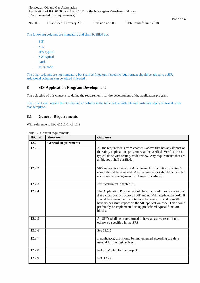
Norwegian Oil and Gas Association Application of IEC 61508 and IEC 61511 in the Norwegian Petroleum Industry (Recommended SIL requirements) No.: 070 Established: February 2001 Revision no.: 03 Date revised: June 2018
192 of 237
The following columns are mandatory and shall be filled out:
- SIF - SIL - HW typical - SW typical - Node - Inter-node
The other columns are not mandatory but shall be filled out if specific requirement should be added to a SIF. Additional columns can be added if needed. 8 SIS Application Program Development The objective of this clause is to define the requirements for the development of the application program. The project shall update the “Compliance” column in the table below with relevant installation/project text if other than template. 8.1 General Requirements With reference to IEC 61511-1, cl. 12.2 Table 12: General requirements
IEC ref. Short text Guidance 12.2 General Requirements
12.2.1
All the requirements from chapter 6 above that has any impact on the safety applications program shall be verified. Verification is typical done with testing, code review. Any requirements that are ambiguous shall clarified.
12.2.2
SRS review is covered in Attachment A. In addition, chapter 6 above should be reviewed. Any inconsistences should be handled according to management of change procedures.
12.2.3
Justification ref. chapter. 3.1
12.2.4
The Application Program should be structured in such a way that it is a clear boarder between SIF and non-SIF application code. It should be shown that the interfaces between SIF and non-SIF have no negative impact on the SIF application code. This should preferably be implemented using predefined typical/function blocks.
12.2.5
All SIF’s shall be programmed to have an active reset, if not otherwise specified in the SRS.
12.2.6
See 12.2.5
12.2.7
If applicable, this should be implemented according to safety manual for the logic solver.
12.2.8
Ref. FSM plan for the project.
12.2.9
Ref. 12.2.8

Norwegian Oil and Gas Association Application of IEC 61508 and IEC 61511 in the Norwegian Petroleum Industry (Recommended SIL requirements) No.: 070 Established: February 2001 Revision no.: 03 Date revised: June 2018
193 of 237
8.2 Application Program Design With reference to IEC 61511-1, cl. 12.3. Table 13: Application program design
IEC ref. Short text Guidance 12.3 Application program design
12.3.1 Process operating modes Process operating modes should be addressed in the programming guideline for the safety system. Process operating modes defined in the SRS should be evaluated to decide if all modes are defined for each SIF. If operation modes are not given as input in the SRS this should be clarified.
12.3.2 Design input General rules defined in the safety manual should be used as the basic requirement for the application program design. Additionally vendor product specifications, architecture, certificates etc. should be taken into consideration
12.3.3 Functional safety assessment – Application program
This document is helping the FSA of the application program
12.3.4 Implementation of requirements
12.3.4 a Safe state Safe state shall be defined in the SRS. The application program safety requirement specification shall identify how this shall be implemented in the application, e.g. NE/NDE, latching, reset etc. If not defined it should be clarified.
12.3.4 b Application program components The software typical used for each SIF shall be identified in the application program safety requirement specification. The 'typicals' selected shall be described in detail in the programming guideline/configuration manual
12.3.4 c Program execution sequence Execution sequence should be defined in the application program safety requirement specification, i.e. input-logic-output. Logic shall be organized to make sure that the involved functions are executed in correct sequence. Execution time to read/write I/O and the application program scan cycle should be evaluated and set to comply with system/function response time requirements
12.3.4 d Standard safety (FB) library Description of the standard safety function block library (if existing). A listing of available function blocks and a reference to the system should be sufficient in the application program safety requirement specification
12.3.4 e Application specific safety modules
Description of additional application specific function blocks (e.g. NORSOK library). SW typicals (e.g. IO driver modules, monitoring block, HMI gateway block) should also be described as part of this section. The application specific custom functions and function blocks should be developed, implemented, tested and documented according to relevant standard (IEC 61508 or IEC 61511)
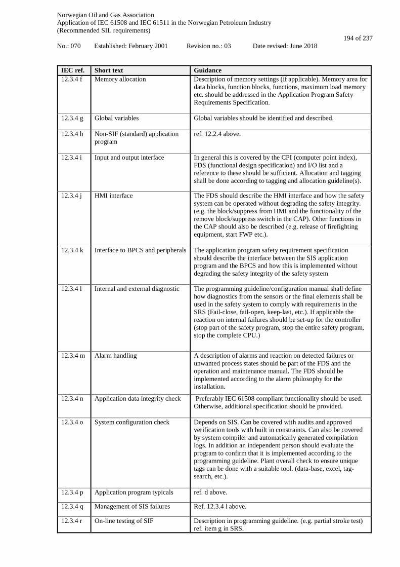
Norwegian Oil and Gas Association Application of IEC 61508 and IEC 61511 in the Norwegian Petroleum Industry (Recommended SIL requirements) No.: 070 Established: February 2001 Revision no.: 03 Date revised: June 2018
194 of 237
IEC ref. Short text Guidance 12.3.4 f Memory allocation Description of memory settings (if applicable). Memory area for
data blocks, function blocks, functions, maximum load memory etc. should be addressed in the Application Program Safety Requirements Specification.
12.3.4 g Global variables Global variables should be identified and described.
12.3.4 h Non-SIF (standard) application program
ref. 12.2.4 above.
12.3.4 i Input and output interface In general this is covered by the CPI (computer point index), FDS (functional design specification) and I/O list and a reference to these should be sufficient. Allocation and tagging shall be done according to tagging and allocation guideline(s).
12.3.4 j HMI interface The FDS should describe the HMI interface and how the safety system can be operated without degrading the safety integrity. (e.g. the block/suppress from HMI and the functionality of the remove block/suppress switch in the CAP). Other functions in the CAP should also be described (e.g. release of firefighting equipment, start FWP etc.).
12.3.4 k Interface to BPCS and peripherals The application program safety requirement specification should describe the interface between the SIS application program and the BPCS and how this is implemented without degrading the safety integrity of the safety system
12.3.4 l Internal and external diagnostic The programming guideline/configuration manual shall define how diagnostics from the sensors or the final elements shall be used in the safety system to comply with requirements in the SRS (Fail-close, fail-open, keep-last, etc.). If applicable the reaction on internal failures should be set-up for the controller (stop part of the safety program, stop the entire safety program, stop the complete CPU.)
12.3.4 m Alarm handling A description of alarms and reaction on detected failures or unwanted process states should be part of the FDS and the operation and maintenance manual. The FDS should be implemented according to the alarm philosophy for the installation.
12.3.4 n Application data integrity check Preferably IEC 61508 compliant functionality should be used. Otherwise, additional specification should be provided.
12.3.4 o System configuration check Depends on SIS. Can be covered with audits and approved verification tools with built in constraints. Can also be covered by system compiler and automatically generated compilation logs. In addition an independent person should evaluate the program to confirm that it is implemented according to the programming guideline. Plant overall check to ensure unique tags can be done with a suitable tool. (data-base, excel, tag-search, etc.).
12.3.4 p Application program typicals ref. d above.
12.3.4 q Management of SIS failures Ref. 12.3.4 l above.
12.3.4 r On-line testing of SIF Description in programming guideline. (e.g. partial stroke test) ref. item g in SRS.
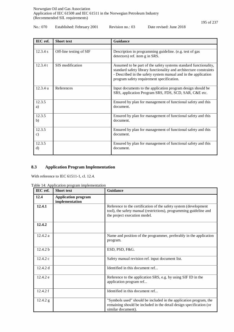
Norwegian Oil and Gas Association Application of IEC 61508 and IEC 61511 in the Norwegian Petroleum Industry (Recommended SIL requirements) No.: 070 Established: February 2001 Revision no.: 03 Date revised: June 2018
195 of 237
IEC ref. Short text Guidance
12.3.4 s Off-line testing of SIF Description in programming guideline. (e.g. test of gas detectors) ref. item g in SRS.
12.3.4 t SIS modification Assumed to be part of the safety systems standard functionality, standard safety library functionality and architecture constraints - Described in the safety system manual and in the application program safety requirement specification.
12.3.4 u References Input documents to the application program design should be SRS, application Program SRS, FDS, SCD, SAR, C&E etc.
12.3.5 a)
Ensured by plan for management of functional safety and this document.
12.3.5 b)
Ensured by plan for management of functional safety and this document.
12.3.5 c)
Ensured by plan for management of functional safety and this document.
12.3.5 d)
Ensured by plan for management of functional safety and this document.
8.3 Application Program Implementation With reference to IEC 61511-1, cl. 12.4. Table 14: Application program implementation
IEC ref. Short text Guidance 12.4 Application program
implementation
12.4.1
Reference to the certification of the safety system (development tool), the safety manual (restrictions), programming guideline and the project execution model.
12.4.2
12.4.2 a
Name and position of the programmer, preferably in the application program.
12.4.2 b
ESD, PSD, F&G.
12.4.2 c
Safety manual revision ref. input document list.
12.4.2 d
Identified in this document ref...
12.4.2 e
Reference to the application SRS, e.g. by using SIF ID in the application program ref...
12.4.2 f
Identified in this document ref...
12.4.2 g
"Symbols used" should be included in the application program, the remaining should be included in the detail design specification (or similar document).

Norwegian Oil and Gas Association Application of IEC 61508 and IEC 61511 in the Norwegian Petroleum Industry (Recommended SIL requirements) No.: 070 Established: February 2001 Revision no.: 03 Date revised: June 2018
196 of 237
IEC ref. Short text Guidance Identified in this document ref...
12.4.2 h
In the application program, together with the SIF's.
12.4.2 i
In the detail design specification, according to the requirements in the application SRS. Identified in this document ref...
12.4.2 j
In the detail design specification, e.g. as a flow chart describing the data processing. Ref. 12.3.4 c) above.
12.4.2 k
Ref. 12.3.4 l and n) above. • In the detail design specification, describe voting, median etc. • Described in the software library • Described in the safety manual (ref. IEC 62443)
12.4.2 l
Described in the safety manual, but the actual version identification and history of changes to be available in the application program.
12.4.3
12.4.3 a
Ref. chapter 3.1.
12.4.3 b
Ref. chapter 3.1.
12.4.3 c
Programming guideline should describe how not used functions shall be controlled (e.g. not used terminals shall be connected to constants).
12.4.4
12.4.4 a
NORSOK functional block library is a recommended way of achieving modularity, e.g. inputs, voting, logic, outputs.
12.4.4 b
ref. 12.4.4 a) above.
12.4.4 c
ref. 12.4.4 a) above.
12.4.4 d
ref. 12.4.4 a) above.
12.4.4 e
Process redundancy should be reflected in the application program. (e.g. Redundant equipment such as fire water pumps). Application program, where the hardware and application is linked together.

Norwegian Oil and Gas Association Application of IEC 61508 and IEC 61511 in the Norwegian Petroleum Industry (Recommended SIL requirements) No.: 070 Established: February 2001 Revision no.: 03 Date revised: June 2018
197 of 237
8.4 Requirement for Application Program Verification With reference to IEC 61511-1, cl. 12.5 Table 15: Requirements for application program verification
IEC ref. Short text Guidance
12.5 Requirements for application program verification (review and testing)
12.5.1
All verification activities should be planned. This can be a separate document or part of the safety life cycle management plan.
12.5.2
It is recommended to have a safety engineer that is independent to the design doing the review. The review should be documented in a review record which show how participated, what they commented and the reviewed application program should be placed under formal change control.
12.5.3
Develop a test strategy during safety planning phase in the project. This test strategy shall address which test techniques that are necessary to use. The test strategy shall also address which kind of test that is necessary and when they shall be ran.
12.5.3 a
This shall be covered in the test specification where the input documents with revision should be identified.
12.5.3 b
The need for this is specified in the test strategy. If needed the test specifications to identify necessary test cases.
12.5.3 c
The need for this is specified in the test strategy. If needed the test specifications to identify necessary test cases.
12.5.3 d
The need for this is specified in the test strategy. If needed the test specifications to identify necessary test cases.
12.5.3 e
This is normally taken care of in all compliant to IEC 61508 logic solvers. If not, this test technique should be identified in the test strategy and test cases described in the test procedures.
12.5.3 f
This is part of the integration test, and when and how the integration test shall be done should be described in the test strategy document.
12.5.3 g
This is part of the integration test, and when and how the integration test shall be done should be described in the test strategy document.
12.5.3 h
This is normally taken care of in all compliant to IEC 61508 logic solvers. If not, this test technique should be identified in the test strategy and test cases described in the test procedures.
12.5.3 i
This shall be covered in the test strategy document, if and when. Test cases covered in the test specifications.
12.5.4
This shall be covered in the test strategy document, if and when. Test cases covered in the test specifications.
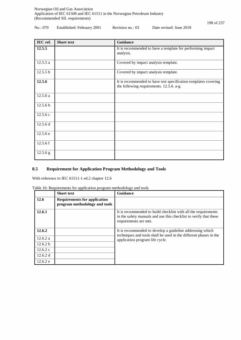
Norwegian Oil and Gas Association Application of IEC 61508 and IEC 61511 in the Norwegian Petroleum Industry (Recommended SIL requirements) No.: 070 Established: February 2001 Revision no.: 03 Date revised: June 2018
198 of 237
IEC ref. Short text Guidance 12.5.5
It is recommended to have a template for performing impact analysis.
12.5.5 a
Covered by impact analysis template.
12.5.5 b
Covered by impact analysis template.
12.5.6
It is recommended to have test specification templates covering the following requirements. 12.5.6. a-g.
12.5.6 a
12.5.6 b
12.5.6 c
12.5.6 d
12.5.6 e
12.5.6 f
12.5.6 g
8.5 Requirement for Application Program Methodology and Tools With reference to IEC 61511-1 ed.2 chapter 12.6 Table 16: Requirements for application program methodology and tools
Short text Guidance 12.6 Requirements for application
program methodology and tools
12.6.1
It is recommended to build checklist with all the requirements in the safety manuals and use this checklist to verify that these requirements are met.
12.6.2
It is recommended to develop a guideline addressing which techniques and tools shall be used in the different phases in the application program life cycle. 12.6.2 a
12.6.2 b
12.6.2 c
12.6.2 d
12.6.2 e
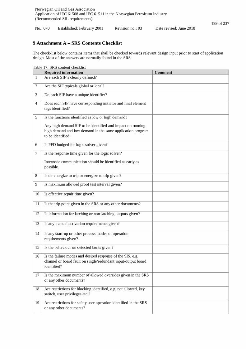
Norwegian Oil and Gas Association Application of IEC 61508 and IEC 61511 in the Norwegian Petroleum Industry (Recommended SIL requirements) No.: 070 Established: February 2001 Revision no.: 03 Date revised: June 2018
199 of 237
9 Attachment A – SRS Contents Checklist The check-list below contains items that shall be checked towards relevant design input prior to start of application design. Most of the answers are normally found in the SRS. Table 17: SRS content checklist
Required information Comment 1 Are each SIF’s clearly defined?
2 Are the SIF typicals global or local?
3 Do each SIF have a unique identifier?
4 Does each SIF have corresponding initiator and final element tags identified?
5 Is the functions identified as low or high demand?
Any high demand SIF to be identified and impact on running high demand and low demand in the same application program to be identified.
6 Is PFD budged for logic solver given?
7 Is the response time given for the logic solver?
Internode communication should be identified as early as possible.
8 Is de-energize to trip or energize to trip given?
9 Is maximum allowed proof test interval given?
10 Is effective repair time given?
11 Is the trip point given in the SRS or any other documents?
12 Is information for latching or non-latching outputs given?
13 Is any manual activation requirements given?
14 Is any start-up or other process modes of operation requirements given?
15 Is the behaviour on detected faults given?
16 Is the failure modes and desired response of the SIS, e.g. channel or board fault on single/redundant input/output board identified?
17 Is the maximum number of allowed overrides given in the SRS or any other documents?
18 Are restrictions for blocking identified, e.g. not allowed, key switch, user privileges etc.?
19 Are restrictions for safety user operation identified in the SRS or any other documents?
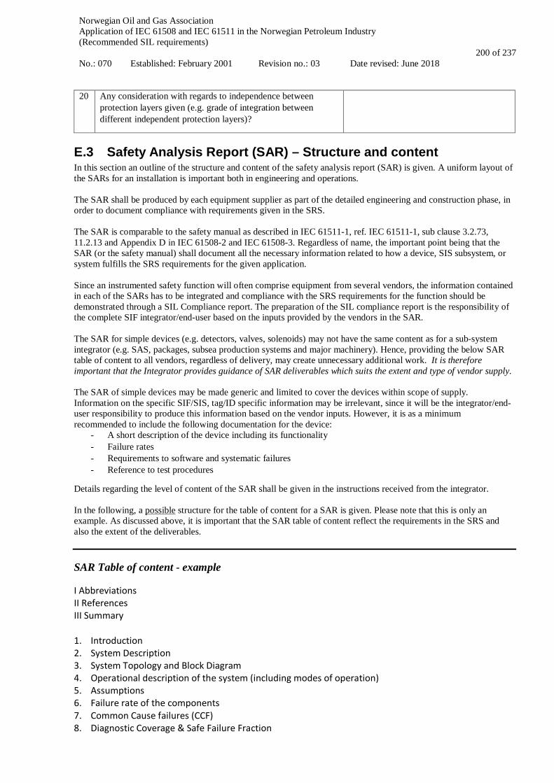
Norwegian Oil and Gas Association Application of IEC 61508 and IEC 61511 in the Norwegian Petroleum Industry (Recommended SIL requirements) No.: 070 Established: February 2001 Revision no.: 03 Date revised: June 2018
200 of 237
20 Any consideration with regards to independence between protection layers given (e.g. grade of integration between different independent protection layers)?
E.3 Safety Analysis Report (SAR) – Structure and content In this section an outline of the structure and content of the safety analysis report (SAR) is given. A uniform layout of the SARs for an installation is important both in engineering and operations. The SAR shall be produced by each equipment supplier as part of the detailed engineering and construction phase, in order to document compliance with requirements given in the SRS. The SAR is comparable to the safety manual as described in IEC 61511-1, ref. IEC 61511-1, sub clause 3.2.73, 11.2.13 and Appendix D in IEC 61508-2 and IEC 61508-3. Regardless of name, the important point being that the SAR (or the safety manual) shall document all the necessary information related to how a device, SIS subsystem, or system fulfills the SRS requirements for the given application. Since an instrumented safety function will often comprise equipment from several vendors, the information contained in each of the SARs has to be integrated and compliance with the SRS requirements for the function should be demonstrated through a SIL Compliance report. The preparation of the SIL compliance report is the responsibility of the complete SIF integrator/end-user based on the inputs provided by the vendors in the SAR. The SAR for simple devices (e.g. detectors, valves, solenoids) may not have the same content as for a sub-system integrator (e.g. SAS, packages, subsea production systems and major machinery). Hence, providing the below SAR table of content to all vendors, regardless of delivery, may create unnecessary additional work. It is therefore important that the Integrator provides guidance of SAR deliverables which suits the extent and type of vendor supply. The SAR of simple devices may be made generic and limited to cover the devices within scope of supply. Information on the specific SIF/SIS, tag/ID specific information may be irrelevant, since it will be the integrator/end-user responsibility to produce this information based on the vendor inputs. However, it is as a minimum recommended to include the following documentation for the device:
- A short description of the device including its functionality - Failure rates - Requirements to software and systematic failures - Reference to test procedures
Details regarding the level of content of the SAR shall be given in the instructions received from the integrator. In the following, a possible structure for the table of content for a SAR is given. Please note that this is only an example. As discussed above, it is important that the SAR table of content reflect the requirements in the SRS and also the extent of the deliverables. SAR Table of content - example I Abbreviations II References III Summary 1. Introduction 2. System Description 3. System Topology and Block Diagram 4. Operational description of the system (including modes of operation) 5. Assumptions 6. Failure rate of the components 7. Common Cause failures (CCF) 8. Diagnostic Coverage & Safe Failure Fraction

Norwegian Oil and Gas Association Application of IEC 61508 and IEC 61511 in the Norwegian Petroleum Industry (Recommended SIL requirements) No.: 070 Established: February 2001 Revision no.: 03 Date revised: June 2018
201 of 237
9. Behaviour of system/components on detection of a fault 10. Factory testing 11. Proof testing 12. Architectural Constraints 13. Avoidance and Control of Systematic Failures 14. Effective time to repair 15. Software documentation 16. Results Appendices ----- I Abbreviations Shall list all relevant abbreviations used. II References Shall list all relevant references with document title, document number, document owner (produced by), date and revision number etc. It shall also include reference to applicable SRS. III Summary The summary shall conclude whether all requirements are met or not. 1 Introduction Shall contain general information and put the SAR into the larger picture/setting. The introduction shall briefly present the supplier’s work process with respect to “Management of functional safety”, e.g. how the requirements have been implemented in the package delivery (see proposed TOC for FSMP in Appendix E.5). 2 System description Shall contain a description of the equipment/component(s) delivered as part of the scope of supply for the package with SIL requirements. Critical equipment/component(s) involved with SIL requirements shall be listed in a table with tag numbers/ID in order to ensure the required traceability where the component is for one specific ID/Tag only. The system description may refer to the Safety Requirement Specification or other documents, which covers the intent of this chapter. The SRS will normally not cover this chapter in sufficient detail. 3 System topology and reliability block diagram Shall contain a description of the arrangement of the system versus the other elements in the safety instrumented function, and interfaces with other systems (in particular with other electronic/ electric/ programmable electronic systems). Shall also give a description of how the components in the SIS are linked together. This chapter may refer to the SRS for overall SIF reliability block diagram. It shall be clearly given which components are the responsibility of the vendor and which are necessary to perform the SIF. 4 Operational description of the system Shall contain a description of how the component(s) shall be operated to fulfil the SIL requirements. Other performance requirements like inhibit, override, capacity and response time shall be documented The design as documented in SIL certificates should be evaluated against the intended use in the specific project under consideration. This e.g. involves a consideration of safe state including allocation between dangerous and safe failures for the product/system in its intended application. 5 Assumptions Shall contain a list of all essential assumptions made regarding the performance of the component(s). Essential assumptions can be assumptions regarding operational environment, maintenance, performance of other components in the SIS (e.g. ability to discover dangerous failures by the automation system), and assumptions related to calculations. 6 Failure rate of the components

Norwegian Oil and Gas Association Application of IEC 61508 and IEC 61511 in the Norwegian Petroleum Industry (Recommended SIL requirements) No.: 070 Established: February 2001 Revision no.: 03 Date revised: June 2018
202 of 237
Shall contain the failure rates of the components covered by the SAR. The failure rates shall as a minimum be given as total failure rate and dangerous undetected failure rate for each component. This chapter shall also document how the failure rates are derived. The information shall be traceable. Failure data can be developed through:
• analysis (ref. IEC 61508-2, annex C) where the classification of dangerous undetected, dangerous detected and safe failures are documented and/or
• by operating data based on historic field experience (The classification of dangerous / safe, detected / undetected failures shall be documented . The applied reliability data shall be traceable.
Safe failure rate should also be documented in this chapter. Reference is made to section 8.5 in main part of guideline for more information about failure data. 7 Common cause failures (CCF) Shall document the probability for common cause failures (CCF). The β-factor model shall be used unless otherwise is agreed with the project/SRS owner. It is recommended that the methodology suggested in IEC 61508-6, annex D is used for developing the β-fraction. Reference is also made to the PDS 2013 data handbook and the report "Common Cause Failures in Safety Instrumented Systems - Beta-factors and equipment specific checklists based on operational experience" (SINTEF 2015, www.sintef.no/pds). 8 Diagnostic coverage & Safe failure fraction Shall (when following IEC 61508) contain calculation of safe failure fraction (SFF) for each component. See section 11.4 in IEC 61511 for alternative routes to fulfill architectural requirements using IEC 61508 or IEC 61511. Diagnostic Coverage (DC) can also be calculated and documented. NOTE: “No-effect” and “no-part failures” shall not play any part in the calculations of the Diagnostic Coverage or the Safe Failure Fraction, ref. IEC 61508-2, Annex C and IEC 61508-6, Annex C. 9 Behaviour of system/components on detection of a fault Shall describe how the system or component will behave on detection of a fault in the system/component. Ref. IEC 61511-1, sub clause 11.3 and IEC 61508-2, sub clause 7.4.8. 10 Factory testing Shall describe how factory acceptance test (FAT) shall be performed and documented. This chapter may refer to other documents like FAT procedures and reports. 11 Proof testing Shall describe how testing of the component(s) shall be performed to be able to maintain the performance claimed during operation. The coverage of the test procedure shall be in accordance with the proof test coverage assumptions used in the calculations. The proof test procedure shall reveal DU failures (as assumed in the proof test coverage) including in redundant channels. 12 Architectural constraints Shall document that the component(s) comply with the requirements for hardware fault tolerance (HFT), as given in tables 2 and 3 in IEC 61508-2, clause 7.4.4.2.2. In this chapter the component shall be classified into type A or type B (see IEC 61508-2, clause 7.4.4.1.2. and 7.4.4.1.3), and by using the required SIL from the SRS and the calculated SFF from chapter 8, verify that the component fulfill the requirements. The reasoning behind classification into either type A or B components should be properly documented. This is particularly important if a type A component is claimed. See sub clause 11.4 in IEC 61511 for alternative routes to fulfill architectural requirements using IEC 61508 or IEC 61511. The architectural constraints apply to all parts of the SIF. If the SAR does not cover all components in a redundant channel application, the Integrator will be responsible for verifying fulfillment of architectural constraints. 13 Avoidance and control of systematic failures Shall describe how the component supplier has ensured that systematic failures are minimised.

Norwegian Oil and Gas Association Application of IEC 61508 and IEC 61511 in the Norwegian Petroleum Industry (Recommended SIL requirements) No.: 070 Established: February 2001 Revision no.: 03 Date revised: June 2018
203 of 237
If compliance with IEC 61508 is claimed, as a minimum, the tables A.15-A.18 in IEC 61508-2 annex A.3 and tables B.2-B.6 in IEC 61508-2 annex B shall be completed. If a component can be documented to be proven in use (ref. IEC 61508-2 sub clause 7.4.10) or prior use (ref IEC 61511 sub clause 11.5.3) it is sufficient that the delivery is done by a company using a structured QA system, e.g. by attaching a relevant ISO 9001 certificate (see also section 8.4 in main part of guideline). 14 Effective time to repair Shall describe the estimated average time spent for repair of the component(s). Only the effective time to repair time is required to be given, as the administrative and logistic delays as well as time for ramp up etc. cannot be properly estimated by the component supplier. 15 Software documentation Shall describe how the component supplier has ensured that the software development is performed within sufficiently controlled forms. See table of content for application program safety requirement specification (Appendix E.2) For components where basis software is covered by a certification the fulfillment of the requirements in IEC 61511-1 clause 12 should be documented. For non-certified components with software the requirements in tables in IEC 61508-3 annex A and B should be fulfilled in addition to documentation of application software according to relevant parts of IEC 61511-1 clause 12. See also Appendix E.2. 16 Results This chapter shall give main results from the report and indicate whether the SIL requirement is complied with or not and, if required, propose measures for fulfilling the SIL requirements. A summary of the result documented in the SAR may be given in the following format.
Table 16.1 Summary of results
<component>
Component identification (tag no)
Test interval
Failure rate (10-6/hour) (λTOT)
Dangerous undetected failure (λDU)
Safe failure fraction (SFF)
Effective repair time
Calculated PFD
Common cause failure (CCF) (β-factor)
Within allocated PFD (Y/N)
Source
Assumption
Comment
16 Appendices E.g. Certificates and certificate reports, Test documentation, FMEDA, Failure reports, PFD calculations and other supporting calculations/documentation.
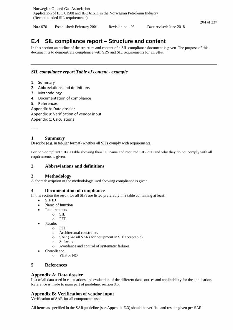
Norwegian Oil and Gas Association Application of IEC 61508 and IEC 61511 in the Norwegian Petroleum Industry (Recommended SIL requirements) No.: 070 Established: February 2001 Revision no.: 03 Date revised: June 2018
204 of 237
E.4 SIL compliance report – Structure and content In this section an outline of the structure and content of a SIL compliance document is given. The purpose of this document is to demonstrate compliance with SRS and SIL requirements for all SIFs. SIL compliance report Table of content - example 1. Summary 2. Abbreviations and definitions 3. Methodology 4. Documentation of compliance 5. References Appendix A: Data dossier Appendix B: Verification of vendor input Appendix C: Calculations ----- 1 Summary Describe (e.g. in tabular format) whether all SIFs comply with requirements. For non-compliant SIFs a table showing their ID, name and required SIL/PFD and why they do not comply with all requirements is given. 2 Abbreviations and definitions 3 Methodology A short description of the methodology used showing compliance is given 4 Documentation of compliance In this section the result for all SIFs are listed preferably in a table containing at least:
• SIF ID • Name of function • Requirements
o SIL o PFD
• Results o PFD o Architectural constraints o SAR (Are all SARs for equipment in SIF acceptable) o Software o Avoidance and control of systematic failures
• Compliance o YES or NO
5 References Appendix A: Data dossier List of all data used in calculations and evaluation of the different data sources and applicability for the application. Reference is made to main part of guideline, section 8.5. Appendix B: Verification of vendor input Verification of SAR for all components used. All items as specified in the SAR guideline (see Appendix E.3) should be verified and results given per SAR

Norwegian Oil and Gas Association Application of IEC 61508 and IEC 61511 in the Norwegian Petroleum Industry (Recommended SIL requirements) No.: 070 Established: February 2001 Revision no.: 03 Date revised: June 2018
205 of 237
Appendix C: Calculations Detailed calculations for all SIF typicals as defined in the SRS Appendix D: Assumptions and limitations Summary of important assumptions and limitations to be follow-up in design, operation and maintenance
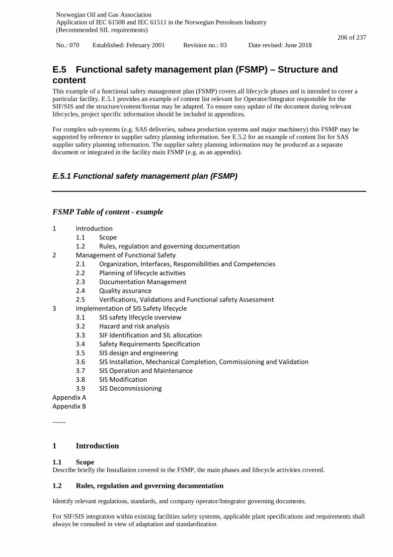
Norwegian Oil and Gas Association Application of IEC 61508 and IEC 61511 in the Norwegian Petroleum Industry (Recommended SIL requirements) No.: 070 Established: February 2001 Revision no.: 03 Date revised: June 2018
206 of 237
E.5 Functional safety management plan (FSMP) – Structure and content This example of a functional safety management plan (FSMP) covers all lifecycle phases and is intended to cover a particular facility. E.5.1 provides an example of content list relevant for Operator/Integrator responsible for the SIF/SIS and the structure/content/format may be adapted. To ensure easy update of the document during relevant lifecycles, project specific information should be included in appendices. For complex sub-systems (e.g. SAS deliveries, subsea production systems and major machinery) this FSMP may be supported by reference to supplier safety planning information. See E.5.2 for an example of content list for SAS supplier safety planning information. The supplier safety planning information may be produced as a separate document or integrated in the facility main FSMP (e.g. as an appendix).
E.5.1 Functional safety management plan (FSMP) FSMP Table of content - example 1 Introduction
1.1 Scope 1.2 Rules, regulation and governing documentation
2 Management of Functional Safety 2.1 Organization, Interfaces, Responsibilities and Competencies 2.2 Planning of lifecycle activities 2.3 Documentation Management 2.4 Quality assurance 2.5 Verifications, Validations and Functional safety Assessment
3 Implementation of SIS Safety lifecycle 3.1 SIS safety lifecycle overview 3.2 Hazard and risk analysis 3.3 SIF Identification and SIL allocation 3.4 Safety Requirements Specification 3.5 SIS design and engineering 3.6 SIS Installation, Mechanical Completion, Commissioning and Validation 3.7 SIS Operation and Maintenance 3.8 SIS Modification 3.9 SIS Decommissioning
Appendix A Appendix B ------ 1 Introduction 1.1 Scope Describe briefly the Installation covered in the FSMP, the main phases and lifecycle activities covered. 1.2 Rules, regulation and governing documentation Identify relevant regulations, standards, and company operator/Integrator governing documents. For SIF/SIS integration within existing facilities safety systems, applicable plant specifications and requirements shall always be consulted in view of adaptation and standardization
Norwegian Oil and Gas Association Application of IEC 61508 and IEC 61511 in the Norwegian Petroleum Industry (Recommended SIL requirements) No.: 070 Established: February 2001 Revision no.: 03 Date revised: June 2018
207 of 237
2 Management of Functional Safety 2.1 Organization, Interfaces, Responsibilities and Competencies Shall describe:
• Roles • Interfaces
For, SIS with interfaces between different contractors scope of supply a SIF/SIS overall responsible shall be identified.
• Discipline responsibilities • Competencies • Assessment of Skills
2.2 Planning of lifecycle activities It is recommended to include only general description of lifecycle activities planning (ref. cl. 5 of IEC 61511-1) and establish project specific list of activities in an appendix to ensure easy update of the document during lifetime. • Activity list, ref. IEC 61511-1, table 2 • Scheduling • Responsible persons and contributors 2.3 Documentation Management
• Life Cycle Information • Document control and Revision Handling • Main Functional safety documentation structure, typically: - Documents to be prepared allowing updates throughout the lifecycle
o Functional Safety Management Plan o Appendix A:
Initial Project specific safety planning information SAS supplier safety planning information, see example in X2
o Appendix B: Modification project safety planning information SAS supplier of modification project safety planning information
o SIF determination and SIL allocation report o Safety requirement specification o SIL compliance report with calculation and data dossier
- Documents that will normally not be updated throughout the lifecycle o Suppliers SAR/Safety Manual o Functional safety assessment report o Verification and validation reports o Follow-up of SIS critical failures in operation and adjustment of maintenance program (to be issued
periodically during SIS operation and maintenance phase) 2.4 Quality assurance
• QA procedures, HSE • Management of change during SIS definition and engineering phases • Management of changes during the operation phase • Non-conformity and deviations handling • Recommendations/actions follow-up and close-out
2.5 Verifications, Validations and Functional safety Assessment

Norwegian Oil and Gas Association Application of IEC 61508 and IEC 61511 in the Norwegian Petroleum Industry (Recommended SIL requirements) No.: 070 Established: February 2001 Revision no.: 03 Date revised: June 2018
208 of 237
• Verification
- Deliverables checks and approval - Design reviews, workshops - Supplier of device delivery verification activities - Factory acceptance tests, simulator tests, integration tests - Inspection
• Validation - Site acceptance test. Ready for operation
• Functional Safety Assessment 3 Implementation of SIS Safety lifecycle Scope, method and working process for each of the SIS safety lifecycle activities should be described either in the FSMP itself or by reference to other relevant document. 3.1 SIS safety lifecycle overview 3.2 Hazard and risk analysis • HAZID/HAZOP and other design reviews 3.3 SIF Identification and SIL allocation • SIF identification and SIL allocation workshop • Approach description: Use of “typical SIF” or risk based approach, identification of deviations to conventional
design • Method/procedure for LOPA/Risk graph or Risk Matrix if applied • Tools 3.4 Safety Requirements Specification 3.5 SIS design and engineering • Reliability data and calculation method • Tests and intervals • Architectural constraints • Device selection by compliance to IEC 61508 or by demonstration of “prior use”/”proven in use” argumentation • Avoidance of systematic failures, including common cause failures • Instructions to suppliers, including:
- Safety planning by supplier (including instructions for documented safety planning by the suppliers of complex sub-systems)
- Issue of SAR/Safety Manual by supplier including instructions per SAR if it shall be generic or project specific
- Access to all information necessary for functional safety assessment • Qualification of SAR/Safety Manual including failure data claim • SIL compliance demonstration • Tools 3.6 SIS Installation, Mechanical Completion, Commissioning and Validation Describe briefly the relevant activities and responsible parties. Commissioning and validation is often responsibility of the integrator or operator. Reference should be made to relevant project commissioning/Validation management document. 3.7 SIS Operation and Maintenance Describe briefly the relevant activities related to SIS in operation and maintenance, typically:

Norwegian Oil and Gas Association Application of IEC 61508 and IEC 61511 in the Norwegian Petroleum Industry (Recommended SIL requirements) No.: 070 Established: February 2001 Revision no.: 03 Date revised: June 2018
209 of 237
• Proof Testing and other maintenance activities • Day-to-day logging and classification of failures • Day-to-day logging of activations (demands and spurious activations) • Day-to-day logging of inhibits/override and compensating measures • Handling of operation in degraded mode, assessment of compensatory measures • Periodical performance evaluation report, including review and classification of safety critical failures,
comparison of observed failure rate/PFD with target, challenge and improve preventive maintenance program (e.g. adjust test interval), identify changes necessary to improve performance of the SIS
Reference should be made to relevant operator’s management system and O&M plans. 3.8 SIS Modification Modification of existing SIS 3.9 SIS Decommissioning Elimination of existing SIS Appendix A • A1 - Initial Project, safety planning information • A2 - SAS supplier, safety planning information, see example in X2 Appendix B • B1 - Modification project, safety planning information • B2 - SAS supplier of modification project, safety planning information
E.5.2 Safety planning information – example for SAS supplier This example only covers lifecycle phases 4 and 5 of the safety lifecycle, ref IEC 61511-1 fig. 7. Safety planning information Table of content – example 1 Introduction
1.1 Scope 1.2 Rules, regulation and governing documentation
2 Management of Functional Safety 2.1 Organization, Interfaces, Responsibilities and Competencies 2.2 Planning of lifecycle activities (V&V) 2.3 Documentation Management 2.4 Quality assurance 2.5 Verifications
3 Implementation of SIS Safety lifecycle phases 4 and 5 3.1 Check for completeness and consistency of customer specification: 3.2 SIS Design and Engineering: 3.3 Installation and commissioning:
Introduction
1.1 Scope

Norwegian Oil and Gas Association Application of IEC 61508 and IEC 61511 in the Norwegian Petroleum Industry (Recommended SIL requirements) No.: 070 Established: February 2001 Revision no.: 03 Date revised: June 2018
210 of 237
Describe the installation/project, contract, product/Scope of supply 1.2 Rules, regulation and governing documentation Identify relevant regulations, standards, customer specifications and requirements and supplier own internal governing documentation. 2 Management of Functional Safety 2.1 Organization, Interfaces, Responsibilities and Competencies • Roles • Interfaces • Responsibilities • Competency • Assessments of skills 2.2 Planning of lifecycle activities (V&V) • Activity list, ref IEC 6151,1 table 3 • Scheduling • Responsible persons and contributors 2.3 Documentation Management • Supplier Master Document List • Document control • Revision handling 2.4 Quality assurance • QA Procedures, HSE • Engineering Handbook • Work process flow chart (phases, activities), • Non-conformity handling • Management of change 2.5 Verification • Verification • Testing • Inspection 3 Implementation of SIS Safety lifecycle phases 4 and 5 3.1 Check for completeness and consistency of customer specification:
• Input requirements (SRS, I/O list, C&E, Functional Description, etc.) 3.2 SIS Design and Engineering: SIS Design and Engineering is an iterative process. A first issue of the SAR/Safety Manual and check that SIS requirements are achievable should be performed early. • Application program SRS: Functional Design Specification, ref. Appendix E.2. • System design • Hardware design • Application design
Norwegian Oil and Gas Association Application of IEC 61508 and IEC 61511 in the Norwegian Petroleum Industry (Recommended SIL requirements) No.: 070 Established: February 2001 Revision no.: 03 Date revised: June 2018
211 of 237
• HMI • Tools • Manufacturing • Documentation (SAR/Safety Manual, etc.) • Configuration Management 3.3 Installation and commissioning:
• Installation • Integration • Testing • Commissioning Describe responsible party and supplier involvement
Norwegian Oil and Gas Association Application of IEC 61508 and IEC 61511 in the Norwegian Petroleum Industry (Recommended SIL requirements) No.: 070 Established: February 2001 Revision no.: 03 Date revised: June 2018
212 of 237
APPLICATION OF IEC 61508 AND IEC 61511
IN THE NORWEGIAN PETROLEUM INDUSTRY
(Recommended SIL requirements)
Appendix F
SIS FOLLOW UP IN THE OPERATIONAL PHASE

Norwegian Oil and Gas Association Application of IEC 61508 and IEC 61511 in the Norwegian Petroleum Industry (Recommended SIL requirements) No.: 070 Established: February 2001 Revision no.: 03 Date revised: June 2018
213 of 237
CONTENT
F.1 VERIFICATION OF SIL REQUIREMENTS DURING OPERATION ................................................ 214
F.2 INFORMATION SOURCES – COLLECTION OF SIS FOLLOW-UP PARAMETERS .................... 216
F.3 UPDATING FAILURE RATES AND TEST INTERVALS BASED ON OPERATIONAL EXPERIENCE ...................................................................................................................................................... 217
F.3.1 RECALCULATING THE FAILURE RATES AND UPDATING THE DATA DOSSIER ............................................. 217 F.3.2 SIMPLIFIED PFD AND FAILURE RATE ESTIMATE ..................................................................................... 217 F.3.3 UPDATE OF FUNCTIONAL TEST INTERVALS ............................................................................................ 218
F.4 ASPECTS RELATED TO SIS TESTING AND MAINTENANCE........................................................ 219 F.4.1 TESTING OF SIF INITIATORS.................................................................................................................. 220 F.4.2 TESTING OF ESD, PSD AND F&G LOGIC ............................................................................................... 220 F.4.3 TESTING OF FINAL ELEMENTS ............................................................................................................... 220
F.5 THE LINK BETWEEN BARRIER MANAGEMENT AND SIL IN OPERATION ............................. 222
F.6 ACTUAL SHUTDOWNS AS TEST ......................................................................................................... 223
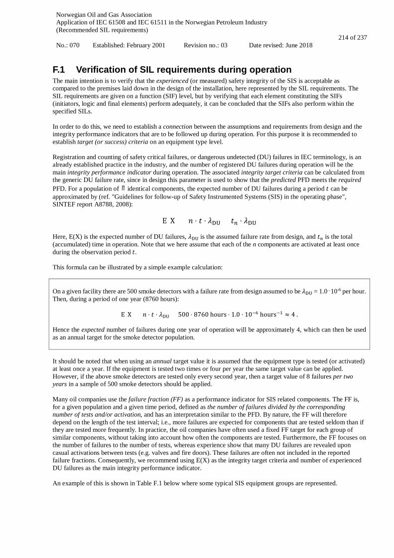
Norwegian Oil and Gas Association Application of IEC 61508 and IEC 61511 in the Norwegian Petroleum Industry (Recommended SIL requirements) No.: 070 Established: February 2001 Revision no.: 03 Date revised: June 2018
214 of 237
F.1 Verification of SIL requirements during operation The main intention is to verify that the experienced (or measured) safety integrity of the SIS is acceptable as compared to the premises laid down in the design of the installation, here represented by the SIL requirements. The SIL requirements are given on a function (SIF) level, but by verifying that each element constituting the SIFs (initiators, logic and final elements) perform adequately, it can be concluded that the SIFs also perform within the specified SILs. In order to do this, we need to establish a connection between the assumptions and requirements from design and the integrity performance indicators that are to be followed up during operation. For this purpose it is recommended to establish target (or success) criteria on an equipment type level. Registration and counting of safety critical failures, or dangerous undetected (DU) failures in IEC terminology, is an already established practice in the industry, and the number of registered DU failures during operation will be the main integrity performance indicator during operation. The associated integrity target criteria can be calculated from the generic DU failure rate, since in design this parameter is used to show that the predicted PFD meets the required PFD. For a population of n identical components, the expected number of DU failures during a period 𝑡𝑡 can be approximated by (ref. "Guidelines for follow-up of Safety Instrumented Systems (SIS) in the operating phase", SINTEF report A8788, 2008):
E(X) = 𝑛𝑛 ⋅ 𝑡𝑡 ⋅ 𝜆𝜆DU = 𝑡𝑡𝑛𝑛 ⋅ 𝜆𝜆DU Here, E(X) is the expected number of DU failures, 𝜆𝜆DU is the assumed failure rate from design, and 𝑡𝑡𝑛𝑛 is the total (accumulated) time in operation. Note that we here assume that each of the n components are activated at least once during the observation period 𝑡𝑡. This formula can be illustrated by a simple example calculation: On a given facility there are 500 smoke detectors with a failure rate from design assumed to be 𝜆𝜆DU = 1.0 . 10-6 per hour. Then, during a period of one year (8760 hours):
E(X) = 𝑛𝑛 ⋅ 𝑡𝑡 ⋅ 𝜆𝜆DU = 500 ⋅ 8760 hours ⋅ 1.0 ⋅ 10−6 hours−1 ≈ 4 . Hence the expected number of failures during one year of operation will be approximately 4, which can then be used as an annual target for the smoke detector population. It should be noted that when using an annual target value it is assumed that the equipment type is tested (or activated) at least once a year. If the equipment is tested two times or four per year the same target value can be applied. However, if the above smoke detectors are tested only every second year, then a target value of 8 failures per two years in a sample of 500 smoke detectors should be applied. Many oil companies use the failure fraction (FF) as a performance indicator for SIS related components. The FF is, for a given population and a given time period, defined as the number of failures divided by the corresponding number of tests and/or activation, and has an interpretation similar to the PFD. By nature, the FF will therefore depend on the length of the test interval; i.e., more failures are expected for components that are tested seldom than if they are tested more frequently. In practice, the oil companies have often used a fixed FF target for each group of similar components, without taking into account how often the components are tested. Furthermore, the FF focuses on the number of failures to the number of tests, whereas experience show that many DU failures are revealed upon casual activations between tests (e.g. valves and fire doors). These failures are often not included in the reported failure fractions. Consequently, we recommend using E(X) as the integrity target criteria and number of experienced DU failures as the main integrity performance indicator. An example of this is shown in Table F.1 below where some typical SIS equipment groups are represented.
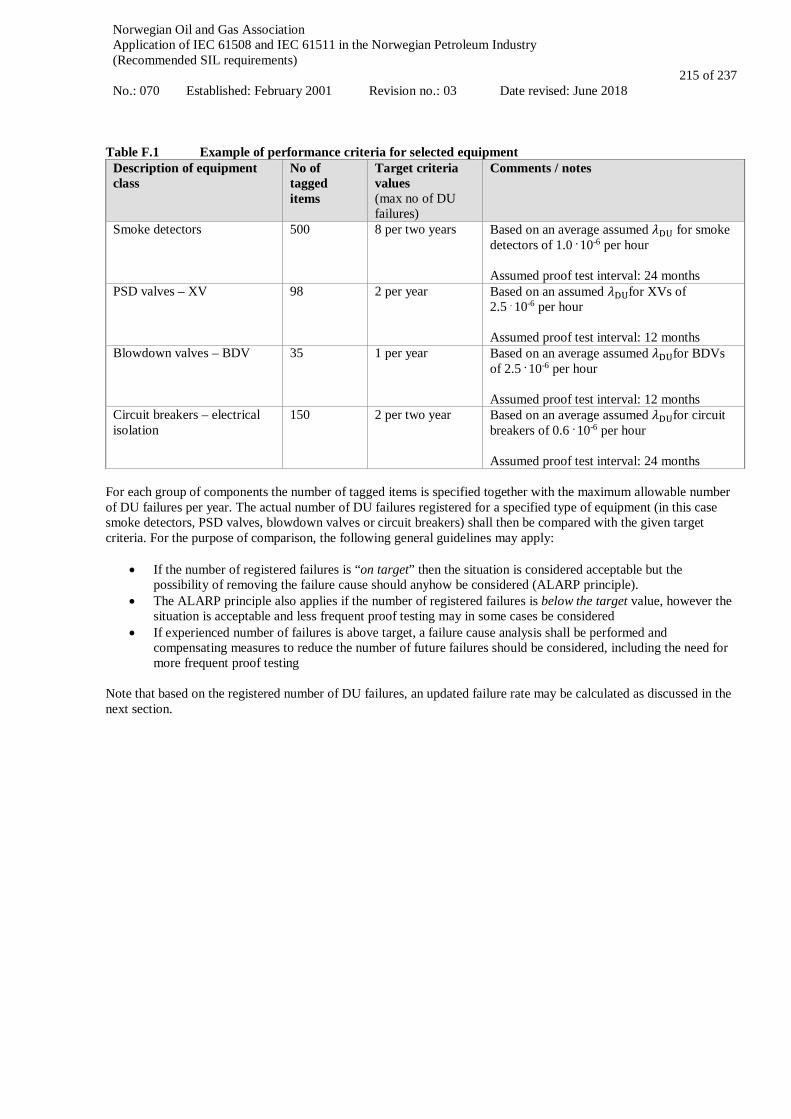
Norwegian Oil and Gas Association Application of IEC 61508 and IEC 61511 in the Norwegian Petroleum Industry (Recommended SIL requirements) No.: 070 Established: February 2001 Revision no.: 03 Date revised: June 2018
215 of 237
Table F.1 Example of performance criteria for selected equipment
Description of equipment class
No of tagged items
Target criteria values (max no of DU failures)
Comments / notes
Smoke detectors 500 8 per two years Based on an average assumed 𝜆𝜆DU for smoke detectors of 1.0 . 10-6 per hour Assumed proof test interval: 24 months
PSD valves – XV
98 2 per year Based on an assumed 𝜆𝜆DUfor XVs of 2.5 . 10-6 per hour Assumed proof test interval: 12 months
Blowdown valves – BDV
35 1 per year Based on an average assumed 𝜆𝜆DUfor BDVs of 2.5 . 10-6 per hour Assumed proof test interval: 12 months
Circuit breakers – electrical isolation
150
2 per two year Based on an average assumed 𝜆𝜆DUfor circuit breakers of 0.6 . 10-6 per hour Assumed proof test interval: 24 months
For each group of components the number of tagged items is specified together with the maximum allowable number of DU failures per year. The actual number of DU failures registered for a specified type of equipment (in this case smoke detectors, PSD valves, blowdown valves or circuit breakers) shall then be compared with the given target criteria. For the purpose of comparison, the following general guidelines may apply:
• If the number of registered failures is “on target” then the situation is considered acceptable but the possibility of removing the failure cause should anyhow be considered (ALARP principle).
• The ALARP principle also applies if the number of registered failures is below the target value, however the situation is acceptable and less frequent proof testing may in some cases be considered
• If experienced number of failures is above target, a failure cause analysis shall be performed and compensating measures to reduce the number of future failures should be considered, including the need for more frequent proof testing
Note that based on the registered number of DU failures, an updated failure rate may be calculated as discussed in the next section.
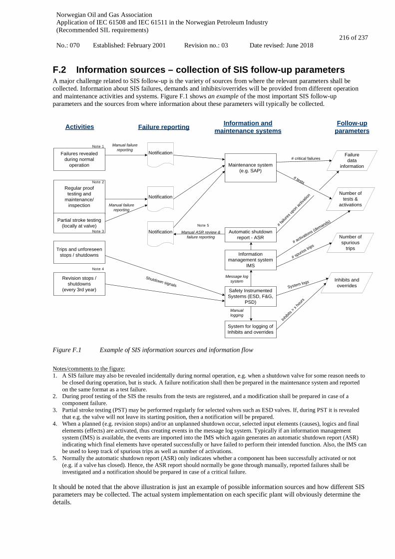
Norwegian Oil and Gas Association Application of IEC 61508 and IEC 61511 in the Norwegian Petroleum Industry (Recommended SIL requirements) No.: 070 Established: February 2001 Revision no.: 03 Date revised: June 2018
216 of 237
F.2 Information sources – collection of SIS follow-up parameters A major challenge related to SIS follow-up is the variety of sources from where the relevant parameters shall be collected. Information about SIS failures, demands and inhibits/overrides will be provided from different operation and maintenance activities and systems. Figure F.1 shows an example of the most important SIS follow-up parameters and the sources from where information about these parameters will typically be collected.
Regular prooftesting and
maintenance/inspection
Activities
Partial stroke testing (locally at valve)
Failures revealed during normal
operation
Information management system
IMS
Failure reporting Information and maintenance systems
Maintenance system(e.g. SAP)
Safety Instrumented Systems (ESD, F&G,
PSD)
Trips and unforeseen stops / shutdowns
Revision stops / shutdowns
(every 3rd year)
Notification
Manual failure reporting
Notification
Follow-up parameters
Shutdown signals
Notification Automatic shutdown report - ASR
Failure data
information
Number of tests &
activations
Number of spurious
trips
# tests
# activations (demands)
Inhibits and overrides
Manual ASR review &failure reporting
Manual failure reporting
System for logging of Inhibits and overrides
# critical failures
System logs
# fail
ures u
pon a
ctiva
tion
Inhibi
ts > x
hours
# spurios trips
Manual logging
Message log system
Note 1
Note 2
Note 3
Note 4
Note 5
Figure F.1 Example of SIS information sources and information flow
Notes/comments to the figure: 1. A SIS failure may also be revealed incidentally during normal operation, e.g. when a shutdown valve for some reason needs to
be closed during operation, but is stuck. A failure notification shall then be prepared in the maintenance system and reported on the same format as a test failure.
2. During proof testing of the SIS the results from the tests are registered, and a modification shall be prepared in case of a component failure.
3. Partial stroke testing (PST) may be performed regularly for selected valves such as ESD valves. If, during PST it is revealed that e.g. the valve will not leave its starting position, then a notification will be prepared.
4. When a planned (e.g. revision stops) and/or an unplanned shutdown occur, selected input elements (causes), logics and final elements (effects) are activated, thus creating events in the message log system. Typically if an information management system (IMS) is available, the events are imported into the IMS which again generates an automatic shutdown report (ASR) indicating which final elements have operated successfully or have failed to perform their intended function. Also, the IMS can be used to keep track of spurious trips as well as number of activations.
5. Normally the automatic shutdown report (ASR) only indicates whether a component has been successfully activated or not (e.g. if a valve has closed). Hence, the ASR report should normally be gone through manually, reported failures shall be investigated and a notification should be prepared in case of a critical failure.
It should be noted that the above illustration is just an example of possible information sources and how different SIS parameters may be collected. The actual system implementation on each specific plant will obviously determine the details.
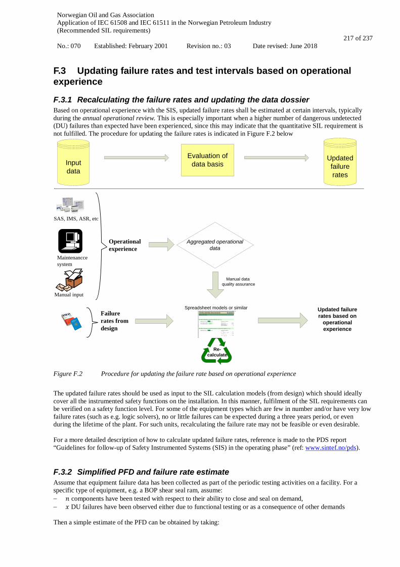
Norwegian Oil and Gas Association Application of IEC 61508 and IEC 61511 in the Norwegian Petroleum Industry (Recommended SIL requirements) No.: 070 Established: February 2001 Revision no.: 03 Date revised: June 2018
217 of 237
F.3 Updating failure rates and test intervals based on operational experience
F.3.1 Recalculating the failure rates and updating the data dossier Based on operational experience with the SIS, updated failure rates shall be estimated at certain intervals, typically during the annual operational review. This is especially important when a higher number of dangerous undetected (DU) failures than expected have been experienced, since this may indicate that the quantitative SIL requirement is not fulfilled. The procedure for updating the failure rates is indicated in Figure F.2 below
Figure F.2 Procedure for updating the failure rate based on operational experience
The updated failure rates should be used as input to the SIL calculation models (from design) which should ideally cover all the instrumented safety functions on the installation. In this manner, fulfilment of the SIL requirements can be verified on a safety function level. For some of the equipment types which are few in number and/or have very low failure rates (such as e.g. logic solvers), no or little failures can be expected during a three years period, or even during the lifetime of the plant. For such units, recalculating the failure rate may not be feasible or even desirable. For a more detailed description of how to calculate updated failure rates, reference is made to the PDS report “Guidelines for follow-up of Safety Instrumented Systems (SIS) in the operating phase” (ref: www.sintef.no/pds).
F.3.2 Simplified PFD and failure rate estimate Assume that equipment failure data has been collected as part of the periodic testing activities on a facility. For a specific type of equipment, e.g. a BOP shear seal ram, assume: − 𝑛𝑛 components have been tested with respect to their ability to close and seal on demand, − 𝑥𝑥 DU failures have been observed either due to functional testing or as a consequence of other demands Then a simple estimate of the PFD can be obtained by taking:
Operational experience
Failure rates from design
Inputdata
Maintenancce system
Updatedfailure rates
Updated failure rates based on
operational experience
Re-calculate
Aggregated operational data
Evaluation of data basis
Manual input
SAS, IMS, ASR, etc
Spreadsheet models or similar
Manual data quality assurance
Norwegian Oil and Gas Association Application of IEC 61508 and IEC 61511 in the Norwegian Petroleum Industry (Recommended SIL requirements) No.: 070 Established: February 2001 Revision no.: 03 Date revised: June 2018
218 of 237
PFD = 𝑥𝑥/2𝑛𝑛 Multiplying by the factor 2 simply reflects the fact that a functional test is performed at the end of the interval. Assume further that the test interval 𝜏𝜏 is known. Then, an estimate of the dangerous failure rate λDU for undetected failures can be obtained by the approximate formula:
𝜆𝜆DU = 𝑥𝑥/(𝑛𝑛 ⋅ 𝜏𝜏), i.e. the number of DU failures divided by the total estimated operational time of the sample. Another way of estimating the failure rate 𝜆𝜆DU based on operational experience is described in the mentioned PDS report. Here, the failure rate estimate �̂�𝜆DU is given by:
�̂�𝜆DU = Number of failuresAggregated time in service
= 𝑥𝑥𝑛𝑛⋅𝑡𝑡
= 𝑥𝑥𝑡𝑡𝑛𝑛
, where 𝑛𝑛 is the number of components in the population of comparable components, 𝑡𝑡 is the observation period and 𝑡𝑡𝑛𝑛 is the total aggregated time in operation. If all components have been in operation, then 𝑡𝑡𝑛𝑛 = 𝑡𝑡 ⋅ 𝑛𝑛. Having obtained an estimate of the failure rate, then an alternative to obtain the PFD is to apply by the simplified formula:
PFD = 𝜆𝜆�DU⋅𝜏𝜏2
.
F.3.3 Update of functional test intervals If operational experience proves that the equipment is significantly more or less reliable than what was assumed in the design phase, extending or reducing the length of the test interval should be considered. Changing the functional test interval is however a major decision which needs to be substantiated by confident quantitative as well as qualitative arguments. A procedure for updating the test intervals, including a discussion of the qualitative aspects that should be part of a decision to change the test intervals, is given in the PDS report “Guidelines for follow-up of Safety Instrumented Systems (SIS) in the operating phase” (ref: www.sintef.no/pds). Here, a separate Excel spreadsheet model for updating failure rates and changing the length of the test interval can also be found.

Norwegian Oil and Gas Association Application of IEC 61508 and IEC 61511 in the Norwegian Petroleum Industry (Recommended SIL requirements) No.: 070 Established: February 2001 Revision no.: 03 Date revised: June 2018
219 of 237
F.4 Aspects related to SIS testing and maintenance A preventive maintenance (PM) program shall be established to ensure that necessary test intervals and test activities are performed in accordance with requirements given for the SIF components. Parameters for tag criticality visibility and overdue reporting systems should be organised in a way such that KPI’s will alert if important test activities are slipping or neglected. Proof testing shall include, but not be limited to, verifying the following:
• operation of all input devices including primary sensors and SIS input modules; • logic associated with each input device; • logic associated with combined inputs; • trip initiating values (set-points) of all inputs; • alarm functions; • speed of response of the SIS when necessary; • operating sequence of the logic program; • function of all final control elements and SIS output modules; • computational functions performed by the SIS; • timing and speed of output devices; • function of the manual trip to bring the system to its safe state; • function of user-initiated diagnostics; • complete system functionality; • the SIS is operational after testing.
A written test philosophy should be established to ensure that all parties involved in testing, operations or modifications have the same understanding of how the test activities are planned and executed. A test philosophy is important for all parties involved and especially for projects and modifications to enable a design which is supporting the testing and monitoring activities. A good design ensures that proof testing can be performed in a safe way, and if possible without having to shut down the system/plant. The effect of incomplete testing (i.e. test coverage < 100%) should be reflected in the PFD calculations. A test philosophy should also explain to what extent the following are used:
• diagnostics tools • partial stroke features • condition monitoring applications • full and partial shutdown requirements
Proof testing of the SIS shall preferably be carried out as an integral-test, i.e. the entire SIF loop should ideally be tested end-to-end (integral). If an integral test is not possible due to safety or operational reasons, a non-integral (partial) test may be performed for each sub-system comprising the SIF loop. If such partial testing is performed, it is important that these tests overlap and cover the whole safety function, ref. overlapping arrows in Figure F.3. It should be noted that although partial proof testing reduces the need to fully test the SIF loop, a complete integral test should still be performed at certain intervals.
Figure F.3: Principal sketch of partial tests
Partialtest 1 Partialtest 2 Partialtest x
SIL x
Norwegian Oil and Gas Association Application of IEC 61508 and IEC 61511 in the Norwegian Petroleum Industry (Recommended SIL requirements) No.: 070 Established: February 2001 Revision no.: 03 Date revised: June 2018
220 of 237
For those applications where partial proof testing is applied, the test procedure shall be written to also include:
• describing the partial testing on the input and logic solver during operation; • testing the final element during unit shut down; • executing the output(s) as far as practical (e.g., output trip relay, shut down solenoid, partial valve
movement) during partial testing
F.4.1 Testing of SIF initiators Testing of SIF initiators shall be performed as per proof test procedures which have been developed for the SIF initiator in question. Use of generic field device test procedures may often fail to reveal dangerous failures which are unique for the specific SIF components (and application), and should normally be avoided if not verified to be suitable. The SIF initiator proof test procedure may have to be tailored explicitly to the field component, something which often is the case for HIPPS and similar systems, but also for e.g. level transmitters. For many other types of field equipment it is often possible to use a common proof test procedure as long as the components work after the same principles and will fail dangerously in comparable ways. The important issue is that we are able to understand and identify the critical failures and to design the tests to reveal all hidden DU failures. The proof test procedures should include a description of dangerous failures with corresponding failure codes to be applied for failure registration. This will help the maintenance personnel to register the correct failure type, and it makes it easier to review the results and statistics later during SIL verification activities. The scheduling of proof test intervals shall be determined via the SIL allocation and verification work and can be found in the SRS and/or the SIL verification documentation.
F.4.2 Testing of ESD, PSD and F&G logic ESD, PSD and F&G logic solvers shall be functionally tested according to intervals specified in the SRS. Beyond this it is important in connection with revision stops and other planned and unplanned shutdowns, to take advantage of information from the SAS and information management (IM) applications to ensure that activated causes and effects function as they should. Testing of logic might be challenging on site so it may be beneficial to plan and perform offsite testing on test systems or simulators. Offsite testing may also provide better possibilities for more extensive testing and also allowing for better time for problems solving etc. The SIS test philosophy should give guidance on how these activities should be organised. A combination of onsite and offsite testing of logic is recommended. E.g. an annual ESD onsite test where selected ESD initiators are tested/used to initiate the ESD level, combined with a four yearly offsite test giving opportunities to test all/multiple initiators.
F.4.3 Testing of final elements Testing of final elements such as e.g. ESVs, BDVs, XVs, fire dampers and circuit breakers shall be performed according to the PM programme. The operator shall identify the safety-critical valves for which leak testing shall be part of the proof testing. Such leak testing shall ensure that the internal leakage rate is within acceptable limits. Furthermore, the operator shall identify the safety-critical valves for which partial stroke testing shall be part of the proof testing. Partial stroke testing may then be included in the PM programme and performed periodically for the selected valves as specified in the SRS. Use of IM applications (automatic shutdown reports, valve trackers etc.) may be useful to record results but may also improve the understanding of which data are received from the system and if the applications are working correctly. Use of IM applications is also beneficial w.r.t. establishing condition monitoring (CM) programs. E.g. a bi-monthly

Norwegian Oil and Gas Association Application of IEC 61508 and IEC 61511 in the Norwegian Petroleum Industry (Recommended SIL requirements) No.: 070 Established: February 2001 Revision no.: 03 Date revised: June 2018
221 of 237
CM program reviewing ESD valves might reveal that an ESD valve is getting sticky. A CM program like this will only look for random or operational valve movements and will not dictate or require a shutdown.
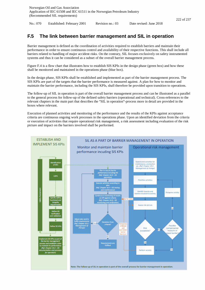
Norwegian Oil and Gas Association Application of IEC 61508 and IEC 61511 in the Norwegian Petroleum Industry (Recommended SIL requirements) No.: 070 Established: February 2001 Revision no.: 03 Date revised: June 2018
222 of 237
F.5 The link between barrier management and SIL in operation Barrier management is defined as the coordination of activities required to establish barriers and maintain their performance in order to ensure continuous control and availability of their respective functions. This shall include all barriers related to handling of major accident risks. On the contrary, SIL focuses exclusively on safety instrumented systems and thus it can be considered as a subset of the overall barrier management process. Figure F.4 is a flow chart that illustrates how to establish SIS KPIs in the design phase (green box) and how these shall be monitored and maintained in the operations phase (blue box). In the design phase, SIS KPIs shall be established and implemented as part of the barrier management process. The SIS KPIs are part of the targets that the barrier performance is measured against. A plan for how to monitor and maintain the barrier performance, including the SIS KPIs, shall therefore be provided upon transition to operations. The follow-up of SIL in operation is part of the overall barrier management process and can be illustrated as a parallel to the general process for follow-up of the defined safety barriers (operational and technical). Cross-references to the relevant chapters in the main part that describes the “SIL in operation”-process more in detail are provided in the boxes where relevant. Execution of planned activities and monitoring of the performance and the results of the KPIs against acceptance criteria are continuous ongoing work processes in the operations phase. Upon an identified deviation from the criteria or execution of activities that require operational risk management, a risk assessment including evaluation of the risk picture and impact on the barriers involved shall be performed.

Norwegian Oil and Gas Association Application of IEC 61508 and IEC 61511 in the Norwegian Petroleum Industry (Recommended SIL requirements) No.: 070 Established: February 2001 Revision no.: 03 Date revised: June 2018
223 of 237
Figure F.4 Relationship between barrier management and SIL in operation (DNV GL figure)
F.6 Actual shutdowns as test An ongoing discussion is to use the results from actual shutdowns as tests, and therefore having the possibility to skip the next planned proof test. To give a rough estimate of the increase in PFD if the next planned functional test is skipped, we shall introduce a specific situation see figure F.5:
• The last proof test was performed at time 𝑡𝑡. • The length of the test interval is 𝜏𝜏. • A shutdown has occurred at time 𝑡𝑡𝑆𝑆, 𝑡𝑡𝑆𝑆 is inside the interval [𝑡𝑡 + 𝜏𝜏/2, 𝑡𝑡 + 𝜏𝜏]; that is, the shutdown was
within the last half of the current test interval. The proof test at time 𝑡𝑡 + 𝜏𝜏 is therefore skipped, and the next test is scheduled at time 𝑡𝑡 + 2𝜏𝜏.
Figure F.5 PFD as a function of time for the two cases “No shutdown” (dashed line) and “Shutdown followed
by skipped test” (solid line).
We want to calculate the increase in PFD (averaged over the lifetime of the system) due to the skipped test. To do so, we make some simplifying assumptions:
• Skipping a proof test will increase the PFD only for the time period until the next test is performed (that is, in the period [𝑡𝑡 + 𝜏𝜏, 𝑡𝑡 + 2𝜏𝜏]). When the average PFD is calculated (over the life-length of the installation), PFD over the limited period will contribute marginally. As a simplification we first calculate PFD over these two test intervals that are affected.
• If we have more than one shutdown within the period [𝑡𝑡, 𝑡𝑡 + 2𝜏𝜏]., this will contribute to reduce the (negative) effect of skipping a test. Thus, we make the simplifying assumption that there is only one shutdown inside the interval.
We can summarize these assumptions by saying that we have selected the most conservative demand rate. I.e., we consider the frequency of demands that gives the worst possible effect on the PFD when the next proof test is skipped. Now, we can calculate the average PFD for the time interval [𝑡𝑡, 𝑡𝑡 + 2𝜏𝜏], and find that the worst-case (that is, when the shutdown occurred exactly at the start of the interval with 𝑡𝑡𝑠𝑠 = 𝜏𝜏/2 leads to PFD = 5/4 ⋅ 𝜆𝜆DU ⋅
𝜏𝜏2, that is, an increase
in the PFD of 25%. The value when we average over 𝑡𝑡𝑠𝑠 inside the interval [𝑡𝑡 + 𝜏𝜏/2, 𝑡𝑡 + 𝜏𝜏] gives an average increase of 8.33% in PFD. This is absolutely worst case. Note that if there for instance is only one demand within say 20 test intervals (rather than one demand in two intervals), the increase in the average PFD is only 0.8%.
time t ts t + τ t + 2τ
PFD (time)
λτ/2

Norwegian Oil and Gas Association Application of IEC 61508 and IEC 61511 in the Norwegian Petroleum Industry (Recommended SIL requirements) No.: 070 Established: February 2001 Revision no.: 03 Date revised: June 2018
224 of 237
Finally, one should notice that although these values show only a moderate increase in the average PFD when a test is skipped, there are some points in time when the PFD is higher than normal. If we only consider the last half of the second test interval (that is, [𝑡𝑡 + 1.5𝜏𝜏, 𝑡𝑡 + 2𝜏𝜏]), then the average PFD in this interval is as high as 2.5 ⋅ 𝜆𝜆DU ⋅ 𝜏𝜏/2. Whether this is acceptable or not should be decided for each case.
Norwegian Oil and Gas Association Application of IEC 61508 and IEC 61511 in the Norwegian Petroleum Industry (Recommended SIL requirements) No.: 070 Established: February 2001 Revision no.: 03 Date revised: June 2018
225 of 237
APPLICATION OF IEC 61508 AND IEC 61511
IN THE NORWEGIAN PETROLEUM INDUSTRY
(Recommended SIL requirements)
Appendix G
INDEPENDENCE BETWEEN SAFETY FUNCTIONS
Norwegian Oil and Gas Association Application of IEC 61508 and IEC 61511 in the Norwegian Petroleum Industry (Recommended SIL requirements) No.: 070 Established: February 2001 Revision no.: 03 Date revised: June 2018
226 of 237
CONTENT
G.1 IMPLEMENTATION OF INDEPENDENCE BETWEEN SYSTEMS ................................................. 227
G.2 CONNECTION BETWEEN SYSTEMS .................................................................................................. 228 G.2.1 CONDITIONALLY ACCEPTABLE SOLUTIONS ............................................................................................ 228
G.3 CONNECTIONS TO EXTERNAL SYSTEMS ....................................................................................... 229 G.3.1 CONDITIONALLY ACCEPTABLE SOLUTIONS ............................................................................................ 229 G.3.2 UNACCEPTABLE SOLUTIONS ................................................................................................................. 230
G.4 DATA FLOW BETWEEN SYSTEMS..................................................................................................... 231
G.4.1 CONDITIONALLY ACCEPTABLE SOLUTIONS ............................................................................................ 231 G.4.2 UNACCEPTABLE SOLUTIONS ................................................................................................................. 236
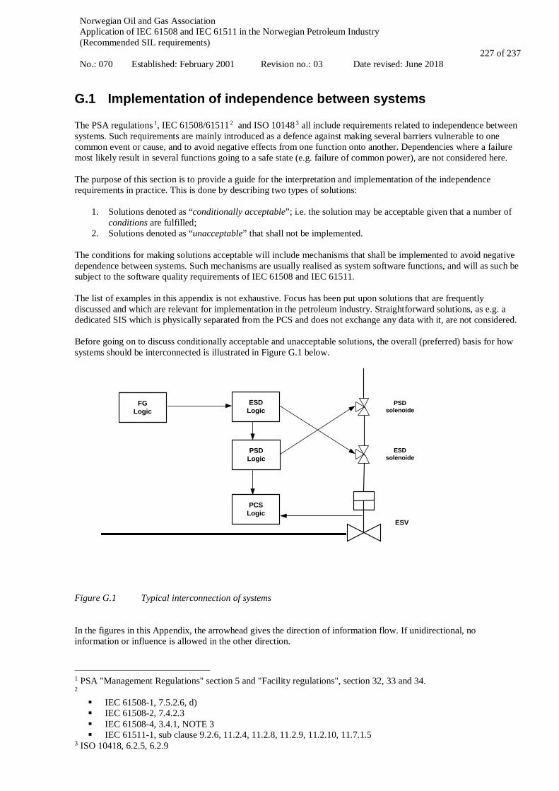
Norwegian Oil and Gas Association Application of IEC 61508 and IEC 61511 in the Norwegian Petroleum Industry (Recommended SIL requirements) No.: 070 Established: February 2001 Revision no.: 03 Date revised: June 2018
227 of 237
G.1 Implementation of independence between systems The PSA regulations 1, IEC 61508/615112 and ISO 101483 all include requirements related to independence between systems. Such requirements are mainly introduced as a defence against making several barriers vulnerable to one common event or cause, and to avoid negative effects from one function onto another. Dependencies where a failure most likely result in several functions going to a safe state (e.g. failure of common power), are not considered here. The purpose of this section is to provide a guide for the interpretation and implementation of the independence requirements in practice. This is done by describing two types of solutions:
1. Solutions denoted as “conditionally acceptable”; i.e. the solution may be acceptable given that a number of conditions are fulfilled;
2. Solutions denoted as “unacceptable” that shall not be implemented. The conditions for making solutions acceptable will include mechanisms that shall be implemented to avoid negative dependence between systems. Such mechanisms are usually realised as system software functions, and will as such be subject to the software quality requirements of IEC 61508 and IEC 61511. The list of examples in this appendix is not exhaustive. Focus has been put upon solutions that are frequently discussed and which are relevant for implementation in the petroleum industry. Straightforward solutions, as e.g. a dedicated SIS which is physically separated from the PCS and does not exchange any data with it, are not considered. Before going on to discuss conditionally acceptable and unacceptable solutions, the overall (preferred) basis for how systems should be interconnected is illustrated in Figure G.1 below.
PSDsolenoide
ESV
ESDsolenoide
FGLogic
PSDLogic
ESDLogic
PCSLogic
Figure G.1 Typical interconnection of systems In the figures in this Appendix, the arrowhead gives the direction of information flow. If unidirectional, no information or influence is allowed in the other direction.
1 PSA "Management Regulations" section 5 and "Facility regulations", section 32, 33 and 34. 2 IEC 61508-1, 7.5.2.6, d) IEC 61508-2, 7.4.2.3 IEC 61508-4, 3.4.1, NOTE 3 IEC 61511-1, sub clause 9.2.6, 11.2.4, 11.2.8, 11.2.9, 11.2.10, 11.7.1.5
3 ISO 10418, 6.2.5, 6.2.9

Norwegian Oil and Gas Association Application of IEC 61508 and IEC 61511 in the Norwegian Petroleum Industry (Recommended SIL requirements) No.: 070 Established: February 2001 Revision no.: 03 Date revised: June 2018
228 of 237
G.2 Connection between systems
G.2.1 Conditionally acceptable solutions
G.2.1.1 Systems interconnected via a common main communications facility
Figure G.2 Systems interconnection via a common communication facility The VDU based HMIs have the physical capability of communicating with any SIS and any PCS. This is a frequently used architecture, with e.g. a dual redundant Ethernet as the common main communications facility. For further requirements concerning communication, ref. IEC 61511-1, cl. 11.7.4. Conditions:
• The SIF with the allocated safety integrity level, shall be realised within the SIS part of the system; • All safety functions shall be designed and programmed to prevent them from failing as a consequence of any
error/event/condition of data transport on the common main communications facility, including total loss of communication;
• The VDU based HMIs shall be equipped with a user authorisation system, restricting access to the safety functions;
• The VDU based HMIs shall be designed in a manner so that it is always evident to the operator whether he/she is currently accessing a safety or non-safety function;
• Dedicated safety system pictures shall be provided and shall be the only means of accessing the function of the SIF from the VDU based HMI (e.g. inhibit, change of parameters, etc.);
• There shall be a separate functional independent hardwired signal, normally this signal is part of the critical action panel (CAP), implemented independently from the common main communications facility and the instrumented systems 4. The CAP shall encompass the action and display elements sufficient for safe operation in the absence of all VDU based HMI. See also NORSOK I-0025.
Maintaining a sufficient degree of independence while using a common backbone bus for both SIS and PCS controllers can be achieved by providing evidence of the following features implemented in the SIS controllers:
• protection against network storms (or guaranteed trip to safe state) • independency of network hang situations (or guaranteed trip to safe state) • protection against faulty telegrams or wrong telegram addressing
4 PSA “Facility regulation”, section 33 concerning Emergency shutdown system ("....It shall be possible to manually activate functions from the manned control centre that bring the facility to a safe condition independently of the parts of the system that can be programmed".) 5 NORSOK I-002, section 4.2.1, item 8 and section 4.2.2 item 15 (.."In addition a functional independent hardwired action panel shall be included")
SIS PCS SIS PCS
HMI HMI
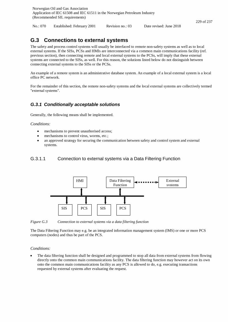
Norwegian Oil and Gas Association Application of IEC 61508 and IEC 61511 in the Norwegian Petroleum Industry (Recommended SIL requirements) No.: 070 Established: February 2001 Revision no.: 03 Date revised: June 2018
229 of 237
G.3 Connections to external systems The safety and process control systems will usually be interfaced to remote non-safety systems as well as to local external systems. If the SISs, PCSs and HMIs are interconnected via a common main communications facility (ref. previous section), then connecting remote and local external systems to the PCSs, will imply that these external systems are connected to the SISs, as well. For this reason, the solutions listed below do not distinguish between connecting external systems to the SISs or the PCSs. An example of a remote system is an administrative database system. An example of a local external system is a local office PC network. For the remainder of this section, the remote non-safety systems and the local external systems are collectively termed "external systems".
G.3.1 Conditionally acceptable solutions Generally, the following means shall be implemented. Conditions:
• mechanisms to prevent unauthorised access; • mechanisms to control virus, worms, etc.; • an approved strategy for securing the communication between safety and control system and external
systems.
G.3.1.1 Connection to external systems via a Data Filtering Function
Figure G.3 Connection to external systems via a data filtering function The Data Filtering Function may e.g. be an integrated information management system (IMS) or one or more PCS computers (nodes) and thus be part of the PCS. Conditions:
• The data filtering function shall be designed and programmed to stop all data from external systems from flowing directly onto the common main communications facility. The data filtering function may however act on its own onto the common main communications facility as any PCS is allowed to do, e.g. executing transactions requested by external systems after evaluating the request.
SIS PCS SIS PCS
HMI Data Filtering Function
External systems
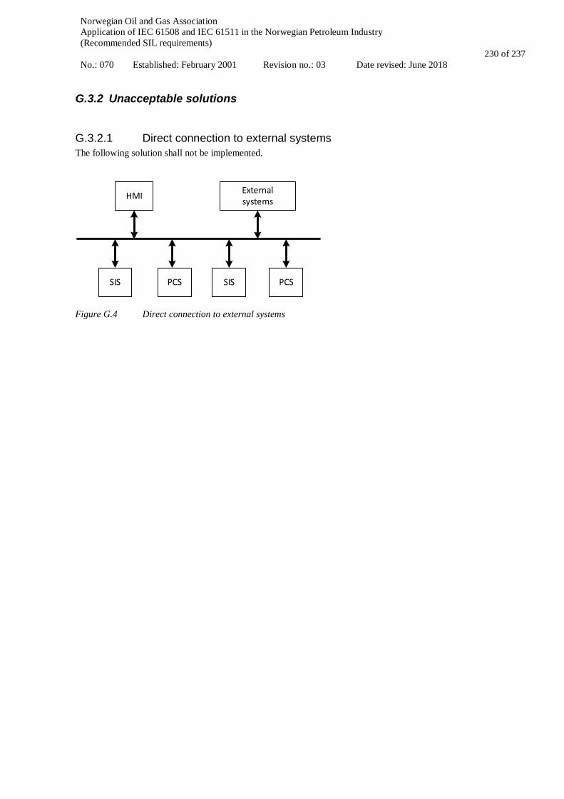
Norwegian Oil and Gas Association Application of IEC 61508 and IEC 61511 in the Norwegian Petroleum Industry (Recommended SIL requirements) No.: 070 Established: February 2001 Revision no.: 03 Date revised: June 2018
230 of 237
G.3.2 Unacceptable solutions
G.3.2.1 Direct connection to external systems The following solution shall not be implemented.
HMI External systems
SIS PCS SIS PCS
Figure G.4 Direct connection to external systems

Norwegian Oil and Gas Association Application of IEC 61508 and IEC 61511 in the Norwegian Petroleum Industry (Recommended SIL requirements) No.: 070 Established: February 2001 Revision no.: 03 Date revised: June 2018
231 of 237
G.4 Data flow between systems The systems considered here is the following:
• Safety systems (SISs): - ESD (Emergency Shutdown System) - FGS (Fire and Gas System) - PSD (Process Shutdown System)
• Non-safety systems: - PCS (Process Control System)
Data flows considered include communication between SISs and between a SIS and the PCS.
G.4.1 Conditionally acceptable solutions
G.4.1.1 Transmitting safety actions between SISs over a common communications facility If safety demands are sent over the backbone network, the safety controller shall be able to monitor the ability to transfer such demands and bring the SIF to a safe state:
• within the defined response-time for the SIF • with a PFD-contribution not compromising the SIL of the complete safety function
Figure G.5 Transmitting safety actions between SIS
The solution may be used for:
- ESD initiating PSD actions - ESD initiating ignition source isolation by FGS - FGS initiating ignition source isolation by ESD - One PSD node initiating PSD actions by another PSD node
Reference is also made to “System interconnected via a common main communication facility” (ref. section G.2.1.1). Conditions:
• Only end to end data address exchange shall be applied, i.e. no intermittent “intelligent” devices (e.g. devices that can change the content of a safety package unnoticed by the receiving end) shall be used;
• The safety system communications protocol shall be implemented with fail-safe functionality. The safety system protocol shall uncover: • Random malfunctions (due to EMI impact on transmission channel); • H/W faults; • Systematic malfunction (transmission fault), H/W or S/W. Hence, the protocol should cover the following types of faults:
• Data corruption The telegram has upon arrival one or more faults compared to the sent telegram
Common, non-safety network SIS 1 SIS 2
Safety function cause Safety function effect
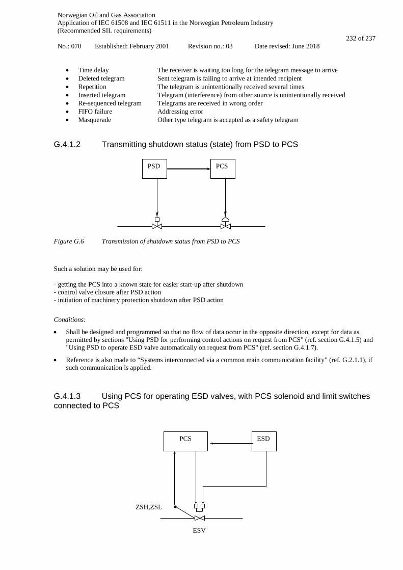
Norwegian Oil and Gas Association Application of IEC 61508 and IEC 61511 in the Norwegian Petroleum Industry (Recommended SIL requirements) No.: 070 Established: February 2001 Revision no.: 03 Date revised: June 2018
232 of 237
• Time delay The receiver is waiting too long for the telegram message to arrive • Deleted telegram Sent telegram is failing to arrive at intended recipient • Repetition The telegram is unintentionally received several times • Inserted telegram Telegram (interference) from other source is unintentionally received • Re-sequenced telegram Telegrams are received in wrong order • FIFO failure Addressing error • Masquerade Other type telegram is accepted as a safety telegram
G.4.1.2 Transmitting shutdown status (state) from PSD to PCS
Figure G.6 Transmission of shutdown status from PSD to PCS
Such a solution may be used for: - getting the PCS into a known state for easier start-up after shutdown - control valve closure after PSD action - initiation of machinery protection shutdown after PSD action
Conditions:
• Shall be designed and programmed so that no flow of data occur in the opposite direction, except for data as permitted by sections "Using PSD for performing control actions on request from PCS" (ref. section G.4.1.5) and "Using PSD to operate ESD valve automatically on request from PCS" (ref. section G.4.1.7).
• Reference is also made to “Systems interconnected via a common main communication facility” (ref. G.2.1.1), if such communication is applied.
G.4.1.3 Using PCS for operating ESD valves, with PCS solenoid and limit switches connected to PCS
PSD PCS
ESV
ZSH,ZSL
ESD PCS

Norwegian Oil and Gas Association Application of IEC 61508 and IEC 61511 in the Norwegian Petroleum Industry (Recommended SIL requirements) No.: 070 Established: February 2001 Revision no.: 03 Date revised: June 2018
233 of 237
Figure G.7 Using PCS for operating ESD valves This solution is typically used for operation of blow down valves during automatic gas purge/pressurisation sequences at process system start-up.
Conditions:
• The pneumatic/hydraulic/mechanical arrangement of the ESV shall be designed and built so that the ESD action is never prevented due to PCS interaction, i.e. to bring the ESV to the safe state.
G.4.1.4. Manual operation of PSD valves
Figure G.8 Manual operation of PSD valves Conditions:
• The PSD system shall be designed and programmed to always prioritise bringing the valve to the safe state if process conditions dictate it, independent of whether the operator has requested opening or closure of the valve.
• Reference is also made to “Systems interconnected via a common main communication facility” (ref. G.2.1.1), if such communication is applied.
G.4.1.5 Using PSD for performing control actions on request from PCS
Figure G.9 Using PSD for performing control actions on request from PCS
This solution is typically used for automated PSD valve operations during process system start-up.
Conditions:
PSD
HMI
XV
PSD PCS
XV

Norwegian Oil and Gas Association Application of IEC 61508 and IEC 61511 in the Norwegian Petroleum Industry (Recommended SIL requirements) No.: 070 Established: February 2001 Revision no.: 03 Date revised: June 2018
234 of 237
• The PSD functions operating the valve are independent of the PCS;
• The PSD system is designed and programmed to always prioritise bringing the valve to the safe state if process conditions dictate it, independent of whether PCS has requested opening or closure of the valve;
• The proper allocation of functions has been made between PCS (e.g. machinery protection) and PSD (process safety); and, the need for the function has been critically evaluated; and, alternative solutions 6 have been explored;
• The architecture of the PSD system shall be such that any failure in the part handling PCS cannot propagate to the part handling PSD and influence its PSD function;
• Shall not be used instead of implementing PSD functionality, i.e. shall not be used for a valve operation that would normally be a PSD action;
• Reference is also made to “Systems interconnected via a common main communication facility” (ref. G.2.1.1), if such communication is applied.
G.4.1.6 Manual operation of ESD valves via PSD, with PSD solenoid and limit switches connected to PSD
Figure G.10 Manual operation of ESV valves via PSD
Conditions:
• The PSD related arrangement of the ESV shall be designed and built such as to never prevent the ESD action, which is to bring the ESV to the safe state.
• The PSD system shall be designed and programmed to always prioritise bringing the valve to the safe state if process conditions or an ESD command dictate it, independent of whether the operator has requested opening or closure of the valve.
• Shall not be used instead of implementing ESD or PSD functionality, i.e. shall not be used for a valve operation that would normally be an ESD or PSD action;
• Reference is also made to “Systems interconnected via a common main communication facility” (ref. G.2.1.1), if such communication is applied.
6 E.g. manual operation of the XV during start-up, or additional solenoid controlled from PCS
ESV ZSH, ZSL
(limit switch)
ESD PSD
HMI

Norwegian Oil and Gas Association Application of IEC 61508 and IEC 61511 in the Norwegian Petroleum Industry (Recommended SIL requirements) No.: 070 Established: February 2001 Revision no.: 03 Date revised: June 2018
235 of 237
G.4.1.7 Using PSD to operate ESD valve automatically on request from PCS
Figure G.11 Using PSD to operate ESD valve upon request from PCS
This solution is typically used for:
- operation of sectioning valves during automatic gas purge/pressurisation sequences at process system start-up - blowdown as part of machinery protection shutdown in PCS
Conditions:
• All conditions in section G.4.1.5 and G.4.1.6 shall be fulfilled
G.4.1.8 Inhibit/override from common operator station
Figure G.12 Inhibit / override from common operator station
Conditions:
• Individual inhibits / overrides shall be logged and feedback status shall be available to the operator, i.e. via the VDU based HMI safety displays.
• The critical action panel (CAP) shall have a global mechanism for easily resetting all currently active inhibits and overrides, covering all the SIS;
• Reference is also made to “Systems interconnected via a common main communication facility” (ref. G.2.1.1), if such communication is applied.
ESV ZSH, ZSL
(limit switch)
ESD PSD PCS
SIS
Operator station
Inhibit/override set/reset action by operator

Norwegian Oil and Gas Association Application of IEC 61508 and IEC 61511 in the Norwegian Petroleum Industry (Recommended SIL requirements) No.: 070 Established: February 2001 Revision no.: 03 Date revised: June 2018
236 of 237
G.4.2 Unacceptable solutions
G.4.2.1 Suppressing PSD action from PCS
Figure G.13 Suppression of PDS action from PCS
In some cases this solution has been used in automated gas compression start-up sequences, in order to avoid PSD shutdown before reaching stable and normal process conditions. This solution shall not be implemented, even though the duration of the suppression is limited by a timeout mechanism in PSD. PSD shutdown upon leakage detection (PALL) on pump/compressor discharge line will in practice not function as a leakage detection and should thus preferably be removed or reclassified as a PCS signal, both cases handled as a deviation to ISO 10418. It may alternatively be permissible to set the action limit as low as to avoid shutdown when the pump/compressor is stopped (i.e. the action limit set below the settle-out pressure). See also Table 7.1 and Appendix A, section A.3.5 for the use PALL as leakage detection.
G.4.2.2 Safety function being totally dependent on operator station
PSD PCS
XV
"Set/reset suppression" command
SIS
Operator station
Manual activation of safety function on operator station, as only mechanism for activation
Action

Norwegian Oil and Gas Association Application of IEC 61508 and IEC 61511 in the Norwegian Petroleum Industry (Recommended SIL requirements) No.: 070 Established: February 2001 Revision no.: 03 Date revised: June 2018
237 of 237
Figure G.14 Manual activation of safety function
This solution, i.e. manual activation via operator station only, shall not be implemented.
The necessary parallel activation mechanism may be implemented in the CAP, see section “Systems interconnected via a common main communication facility” above (ref. G.2.1.1). There shall be a SIL requirement on such CAP functions, ref. Table 7.1 and Appendix A, section A.16.
G.4.2.3 Data transport from PSD to FGS Solutions implying flow of data from PSD to FGS shall not be implemented.
G.4.2.4 Data transport from PSD to ESD Solutions implying flow of data from PSD to ESD shall not be implemented.