07 Fracture
38
Suranaree University of Technology May-Aug 2007 Fracture Fracture Subjects of interest • Introduction/ objectives • Types of fracture in metals • Theoretical cohesive strength of metals • The development in theories of brittle fracture • Fractographic observation in brittle fracture • Ductile fracture • Ductile to brittle transition behaviour • Intergranular fracture • Factors affecting modes of fracture • Concept of the fracture curve Chapter 7 Tapany Udomphol
-
Upload
takorn-weyhey -
Category
Documents
-
view
195 -
download
18
Transcript of 07 Fracture
Suranaree University of Technology May-Aug 2007
FractureFracture
Subjects of interest
• Introduction/ objectives
• Types of fracture in metals
• Theoretical cohesive strength of metals
• The development in theories of brittle fracture
• Fractographic observation in brittle fracture
• Ductile fracture
• Ductile to brittle transition behaviour
• Intergranular fracture
• Factors affecting modes of fracture
• Concept of the fracture curve
Chapter 7
Tapany Udomphol
Suranaree University of Technology May-Aug 2007
ObjectivesObjectives
• This chapter provides the development in the
theories of brittle fractures together with mechanisms
of fracture that might occur in metallic materials.
• Factors affecting different types of fracture
processes such as brittle cleavage fracture, ductile
failure or intergranular fracture will be discussed.
Tapany Udomphol

Suranaree University of Technology May-Aug 2007
IntroductionIntroduction
Failure in structures leads to lost of
properties and sometimes lost of
human lives unfortunately.
Failure of Liberty Ships during
services in World War II.Collapse of Point Pleasant suspension
bridge, West Virginia, 1967.
Failed fuselage of the Aloha 737
aircraft in 1988.
Tapany Udomphol

Suranaree University of Technology May-Aug 2007
Types of fracture in metalsTypes of fracture in metals
• The concept of material strength and fractures has long been
studied to overcome failures.
• The introduction of malleable irons during the revolution of
material construction led to the perception of brittle and ductile
fractures as well as fatigue failure in metals.
Ductile failure
Brittle failure
Failure in metallic materials
can be divided into two
main categories;
Brittle fracture is more catastrophic
and has been intensively studied.
Ductile fracture involves a large
amount of plastic deformation and
can be detected beforehand.
Theories of brittle fracture
Tapany Udomphol

Suranaree University of Technology May-Aug 2007
Failure modes
Ductile fracture Brittle fracture
• High energy is absorbed by
microvoid coalescence during
ductile failure (high energy
fracture mode)
Less catastrophic
• Low energy is absorbed during
transgranular cleavage fracture
(low energy fracture mode)
More catastrophic
Tapany Udomphol

Suranaree University of Technology May-Aug 2007
Theoretical cohesive strength of Theoretical cohesive strength of
metalmetal
• In the most basic term, strength is due to the cohesive forces
between atoms.
• The attractive and repulsive force acting on the two atoms
lead to cohesive force between two atoms which varies in
relation to the separation between these atoms, see fig.
The theoretical cohesive strength
σσσσmax can be obtained in relation to
the sine curve and become.
21
max
=
o
s
a
Eγσ ...Eq. 1
Note: Convenient estimates of σσσσmax ~ E/10.
σσσσmax
Co
hesiv
e f
orc
e, σσ σσ
ao
Separation
between
atoms, x
Cohesive force as a function of
the separation between atoms.
Where
γγγγs is the surface energyao is the unstrained interatomic spacing.
Tapany Udomphol
Suranaree University of Technology May-Aug 2007
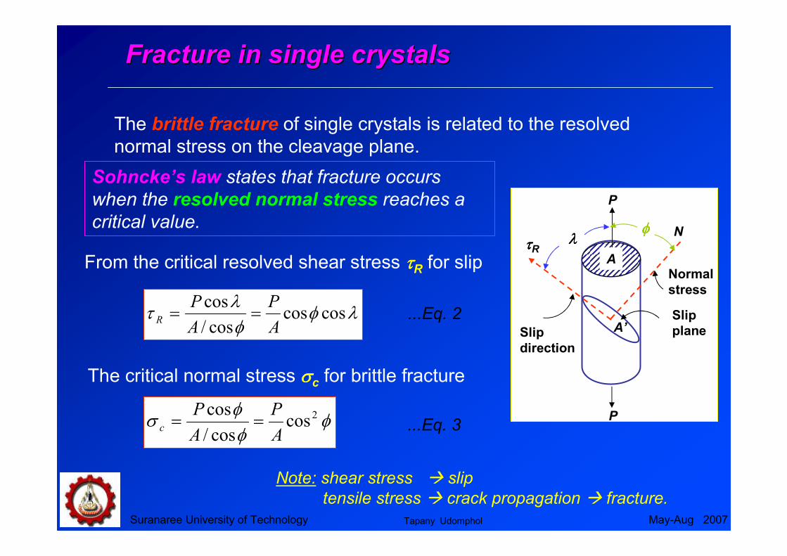
Fracture in single crystalsFracture in single crystals
The brittle fracture of single crystals is related to the resolved
normal stress on the cleavage plane.
N
A
P
ττττR
Slip
direction
Slip
plane
φφφφλλλλ
P
A’
Note: shear stress � slip
tensile stress � crack propagation � fracture.
From the critical resolved shear stress ττττR for slip
λφφλ
τ coscoscos/
cos
A
P
A
PR ==
φφφ
σ 2coscos/
cos
A
P
A
Pc ==
...Eq. 2
...Eq. 3
The critical normal stress σσσσc for brittle fracture
Sohncke’s law states that fracture occurs
when the resolved normal stress reaches a
critical value.
Normal
stress
Tapany Udomphol
Suranaree University of Technology May-Aug 2007
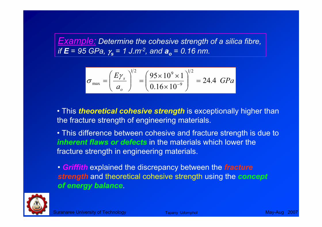
Example: Determine the cohesive strength of a silica fibre,
if E = 95 GPa, γγγγs = 1 J.m-2, and ao = 0.16 nm.
GPaa
E
o
s 4.241016.0
1109521
9
921
max =
×
××=
=
−
γσ
• This theoretical cohesive strength is exceptionally higher than
the fracture strength of engineering materials.
• This difference between cohesive and fracture strength is due to
inherent flaws or defects in the materials which lower the
fracture strength in engineering materials.
• Griffith explained the discrepancy between the fracture
strength and theoretical cohesive strength using the concept
of energy balance.
Tapany Udomphol

Suranaree University of Technology May-Aug 2007
Theories of brittle fractureTheories of brittle fracture
Griffith theory of brittle fracture
The development in cleavage fracture models
• Modified Griffith theory by Irwin and Orowan.
• Zener’s model of microcrack formation at a pile-up of
edge dislocations.
• Stroh’s model of cleavage crack formation by dislocation
pile-up.
• Cottrell’s model of cleavage crack initiation in BCC metals
• Smith’s model of microcrack formation in grain boundary
carbide film.
The first analysis on cleavage fracture was initiated by Griffith
using the concept of energy balance in order to explain
discrepancy between the theoretical cohesive strength and
observed fracture strength of ideally brittle material.
Tapany Udomphol
Suranaree University of Technology May-Aug 2007
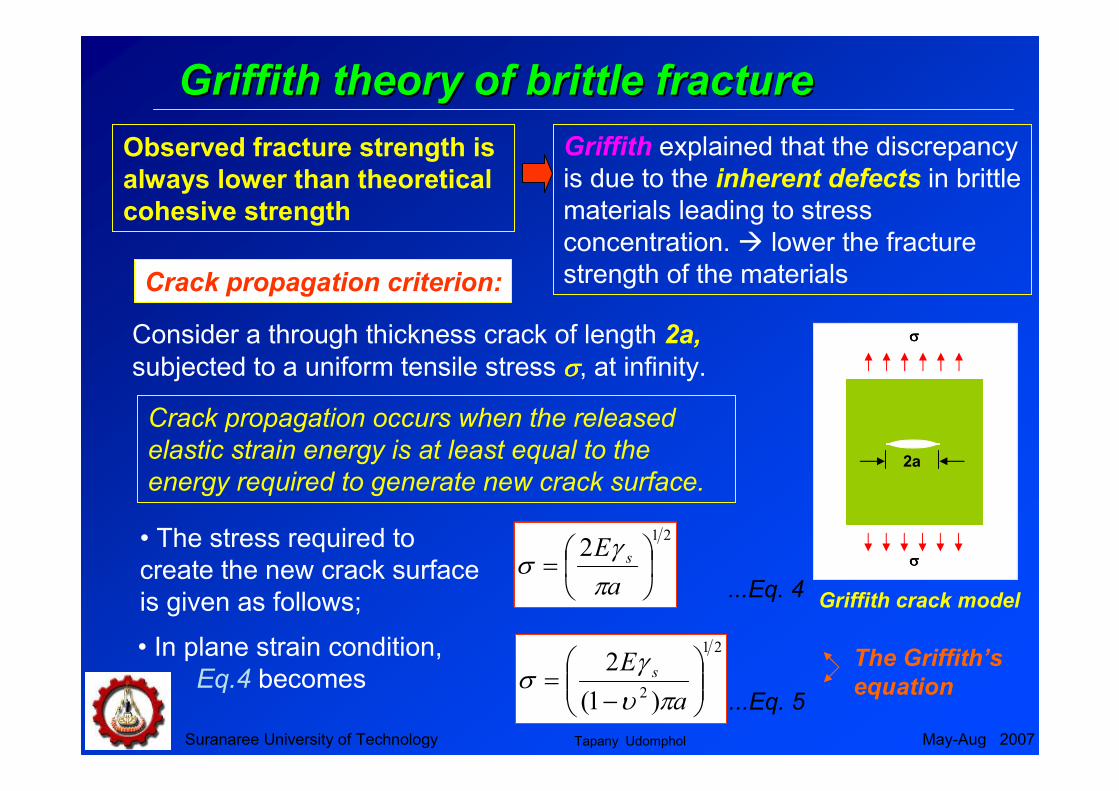
Griffith theory of brittle fractureGriffith theory of brittle fracture
Griffith explained that the discrepancy
is due to the inherent defects in brittle
materials leading to stress
concentration. � lower the fracture
strength of the materials
Observed fracture strength is
always lower than theoretical
cohesive strength
Crack propagation criterion:
Crack propagation occurs when the released
elastic strain energy is at least equal to the
energy required to generate new crack surface.2a
σσσσ
σσσσ
Griffith crack model
Consider a through thickness crack of length 2a,
subjected to a uniform tensile stress σσσσ, at infinity.
• The stress required to
create the new crack surface
is given as follows;
212
=
a
E s
πγ
σ...Eq. 4
The Griffith’s
equation
21
2 )1(
2
−=
a
E s
πυγ
σ...Eq. 5
• In plane strain condition,
Eq.4 becomes
Tapany Udomphol

Suranaree University of Technology May-Aug 2007
Modified Griffith equationModified Griffith equation
• The Griffith equation is strongly dependent on the crack size a,
and satisfies only ideally brittle materials like glass.
• Irwin and Orowan suggested Griffith’s equation can be
applied to brittle materials undergone plastic deformation
before fracture by including the plastic work, γγγγp, into the total elastic surface energy required to extend the crack wall, giving
the modified Griffith’s equation as follows
2
21
2
21
2,
)1()1(
)(2γγ
υ
γ
υπ
γγσ >>
−≈
−
+= p
pps
f whena
E
a
E...Eq. 6
• However, metals are not ideally brittle and normally fail with
certain amounts of plastic deformation, the fracture stress is
increased due to blunting of the crack tip.
Tapany Udomphol
Suranaree University of Technology May-Aug 2007
Zener’s model of microcrack formation
at a pile-up of edge dislocations
Dislocation pile-ups at barrier.
ττττs
L 2c
Barrier
Source
nb
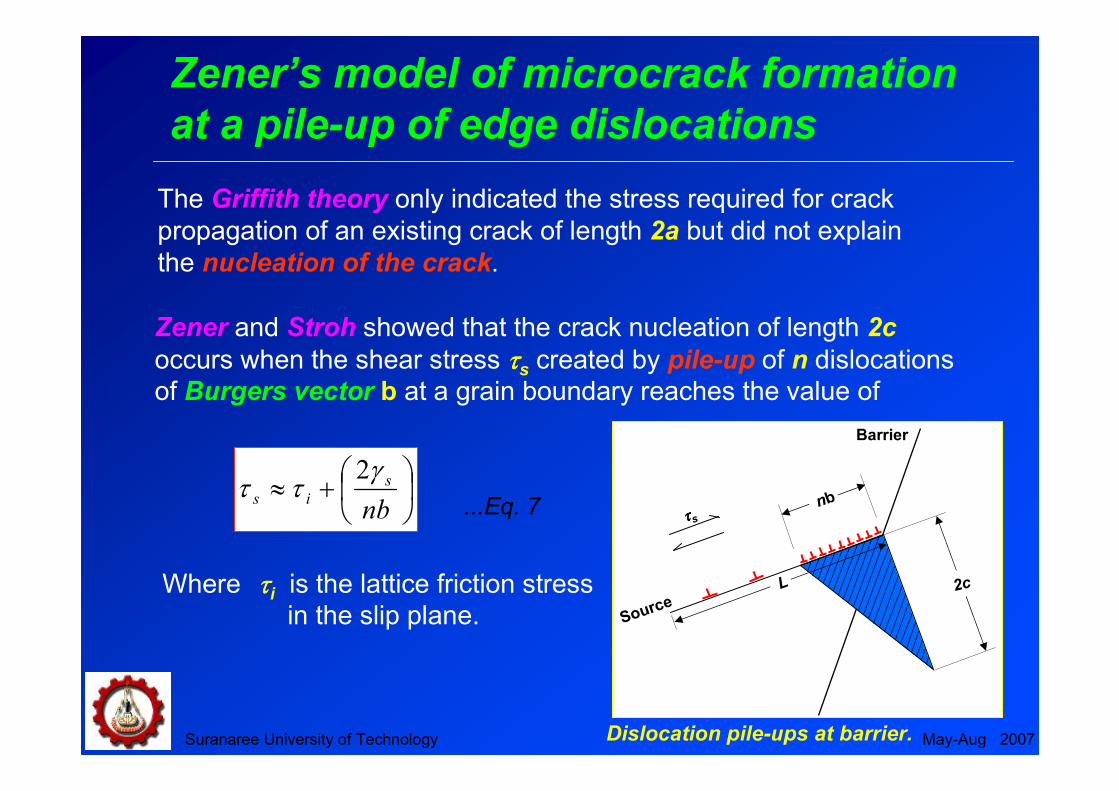
The Griffith theory only indicated the stress required for crack
propagation of an existing crack of length 2a but did not explain
the nucleation of the crack.
Zener and Stroh showed that the crack nucleation of length 2c
occurs when the shear stress ττττs created by pile-up of n dislocations of Burgers vector b at a grain boundary reaches the value of
+≈nb
s
is
γττ
2
...Eq. 7
Where ττττi is the lattice friction stress in the slip plane.

Suranaree University of Technology May-Aug 2007
Stroh’s model of cleavage crack
formation by dislocation pile-up
r
σσσσθθθθθθθθ
σσσσθθθθθθθθ
σσσσθθθθθθθθ
d/2
ττττ−−−−ττττl
Dislocation pile-up
forming micocrack
r
Stroh included the effect of the grain size d in a model, suggesting
the condition of the shear stress created by dislocation pile-up of
the length d/2 to nucleate a microcrack as follows
( )dE
iyeff 214 υπγ
τττ−
−=
where
ττττeff is the effective shear stress
ττττy is the yield stress
...Eq. 8
Note: This model indicates that the
fracture of the material should depend
only on the shear stress acting on the
slip band.
Stroh’s model of cleavage crack
formation by dislocation pile-up.
Tapany Udomphol
Suranaree University of Technology May-Aug 2007
Cottrell’s model of cleavage crack
initiation in BCC metals
(001) Cleavage plane
[ ]1112
a
(101) Slip plane
(101) Slip plane
[ ]1112
a
[ ]001ab =
Applied stress
σσσσ
σσσσ
Cleavage knife crack
of length c for
displacement nb
[ ] [ ] [ ]0011112
1112
aaa
→+
Cottrell’s model of cleavage crack
initiation in BCC metals
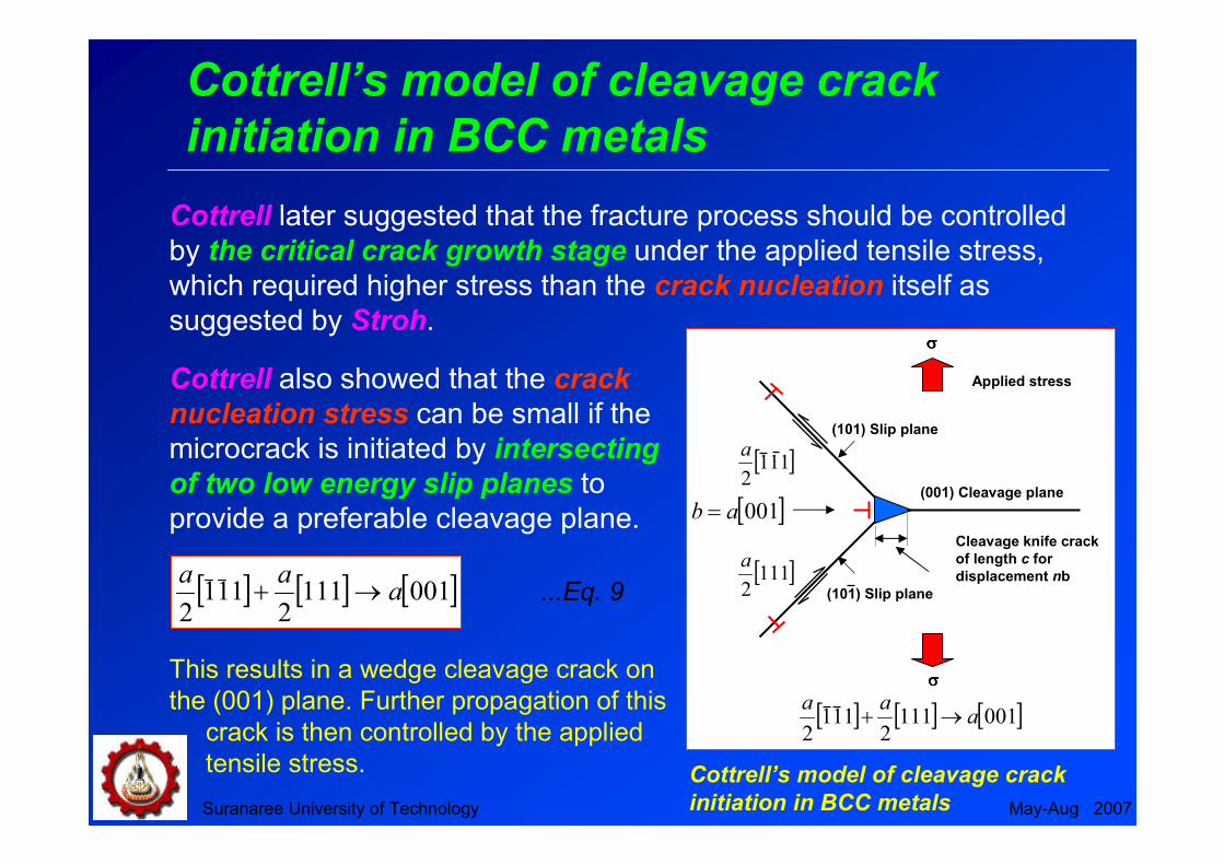
Cottrell later suggested that the fracture process should be controlled
by the critical crack growth stage under the applied tensile stress,
which required higher stress than the crack nucleation itself as
suggested by Stroh.
Cottrell also showed that the crack
nucleation stress can be small if the
microcrack is initiated by intersecting
of two low energy slip planes to
provide a preferable cleavage plane.
[ ] [ ] [ ]0011112
1112
aaa
→+ ...Eq. 9
This results in a wedge cleavage crack on
the (001) plane. Further propagation of this
crack is then controlled by the applied
tensile stress.
Suranaree University of Technology May-Aug 2007
Smith’s model of microcrack formation
in grain boundary carbide film
Microcrack
Grain boundary carbide film
Ferrite grain
D
ττττeff
ττττeff
Ferrite grain
Co
σ
σ
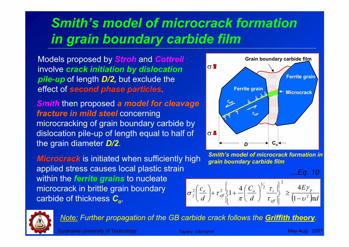
Smith then proposed a model for cleavage
fracture in mild steel concerning
microcracking of grain boundary carbide by
dislocation pile-up of length equal to half of
the grain diameter D/2.
Models proposed by Stroh and Cottrell
involve crack initiation by dislocation
pile-up of length D/2, but exclude the
effect of second phase particles.
Smith’s model of microcrack formation in
grain boundary carbide film
( ) dE
d
C
d
c p
eff
io
eff
o
f πυ
γ
ττ
πτσ
2
2
21
22
1
441
−≥
++
...Eq. 10
Microcrack is initiated when sufficiently high
applied stress causes local plastic strain
within the ferrite grains to nucleate
microcrack in brittle grain boundary
carbide of thickness Co.
Note: Further propagation of the GB carbide crack follows the Griffith theory.
Tapany Udomphol

Suranaree University of Technology May-Aug 2007
Fractographic observation
in brittle fracture
1) Plastic deformation to produce
dislocation pile-ups.
2) Crack initiation.
3) Crack propagation to failure.
Brittle fracture indicating the origin of the
crack and crack propagation path
The process of cleavage fracture
consists of three steps:
Distinct characteristics of brittle
fracture surfaces:
1) The absence of gross plastic
deformation.
2) Grainy or Faceted texture.
3) River marking or stress lines.
Tapany Udomphol

Brittle fracture surface
Suranaree University of Technology May-Aug 2007
• Cleavage fracture surface is
characterised by flat facets (with its size
normally similar to the grain size).
• River lines or the stress lines are steps
between cleavage on parallel planes and
always converge in the direction of local
crack propagation.
River marking
or stress lines
Brittle cleavage facet
Cleavage facet
Schematic of river-line pattern.
Crack
growth
directionTwist boundary
Fatigue pre-crack front
Tapany Udomphol
Initiation of microcracks from
deformation and twins
Suranaree University of Technology May-Aug 2007
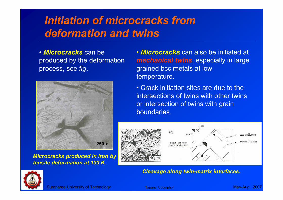
Microcracks produced in iron by
tensile deformation at 133 K.
250 x
• Microcracks can also be initiated at
mechanical twins, especially in large
grained bcc metals at low
temperature.
• Crack initiation sites are due to the
intersections of twins with other twins
or intersection of twins with grain
boundaries.
• Microcracks can be
produced by the deformation
process, see fig.
Cleavage along twin-matrix interfaces.
Tapany Udomphol

Crack initiation from particles in
cleavage fracture
• Inclusions, porosity, second-
phase particles or precipitates are
preferential sites (stress raiser)
for cleavage initiation.
Suranaree University of Technology May-Aug 2007
Crack initiation site
• Fracture occurs along the
crystallographic planes.
• The direction of the river
pattern represents the direction
of the crack propagation.Tapany Udomphol
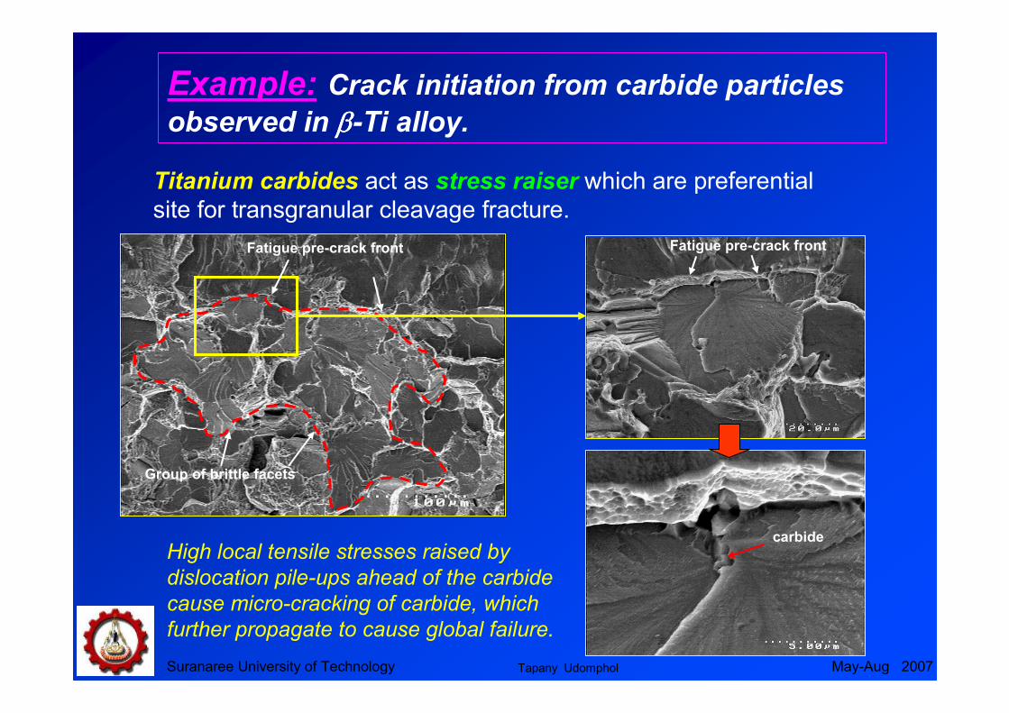
Example: Crack initiation from carbide particles
observed in ββββ-Ti alloy.
Titanium carbides act as stress raiser which are preferential
site for transgranular cleavage fracture.
Suranaree University of Technology May-Aug 2007
carbide
Fatigue pre-crack frontFatigue pre-crack front
Group of brittle facets
High local tensile stresses raised by
dislocation pile-ups ahead of the carbide
cause micro-cracking of carbide, which
further propagate to cause global failure.
Tapany Udomphol
Suranaree University of Technology May-Aug 2007
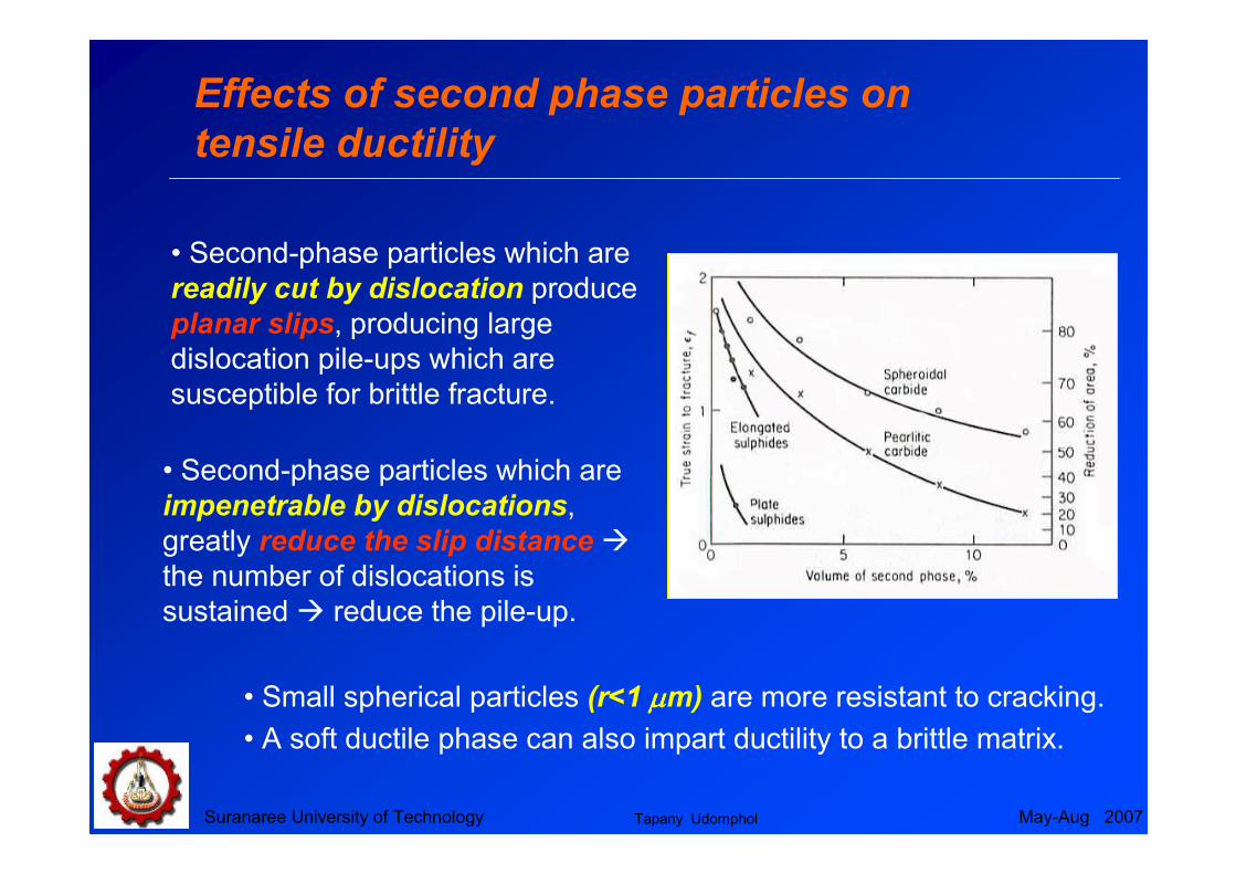
Effects of second phase particles on
tensile ductility
• Second-phase particles which are
readily cut by dislocation produce
planar slips, producing large
dislocation pile-ups which are
susceptible for brittle fracture.
• Second-phase particles which are
impenetrable by dislocations,
greatly reduce the slip distance �
the number of dislocations is
sustained � reduce the pile-up.
• Small spherical particles (r<1 µµµµm) are more resistant to cracking.
• A soft ductile phase can also impart ductility to a brittle matrix.
Tapany Udomphol

Suranaree University of Technology May-Aug 2007
Ductile fractureDuctile fracture
Ductile fracture is a much less serious
problem in engineering materials since
failure can be detected beforehand due
to observable plastic deformation
prior to failure.
• Under uniaxial tensile force, after
necking, microvoids form and
coalesce to form crack, which then
propagate in the direction normal to
the tensile axis.
• The crack then rapidly propagate
through the periphery along the shear
plane at 45o, leaving the cub and
cone fracture.
Stages in cup and cone fracture
NeckingMicrovoid
formation and
coalescence
Crack
propagation
Propagation along
shear plane
Typical cup and
cone fracture

Suranaree University of Technology May-Aug 2006
Microvoid formation, growth and Microvoid formation, growth and
coalescencecoalescence
• Microoids are easily formed at inclusions,
intermetallic or second-phase particles and
grain boundaries.
• Growth and coalescence of microvoids
progress as the local applied load
increases.
a) Random planar array
of particles acting as
void initiators.
b) Growth of voids to join
each other as the applied
stress increases.
c) Linkage or coalescence
of these voids to form free
fracture surface.
Ductile dimples centred on
spherical particles
Tapany Udomphol

Suranaree University of Technology May-Aug 2007
Formation of microvoids from second Formation of microvoids from second
phase particlesphase particles
Mechanisms of microvoid formation
1) Decohesion at particle-matrix interface.
2) Fracture of brittle particle
3) Decohesion of an interface associated
with shear deformation or grain
boundary sliding.
Microvoids are formed by
Fractured carbide
Decohesion of carbide particles
from Ti matrix.
Fractured carbides aiding
microvoid formation.
Tapany Udomphol

Suranaree University of Technology May-Aug 2007
Microvoid shapeMicrovoid shape
Microvoid shape is strongly influenced by the type of loading.
Uniaxial tensile loading
� Equiaxed dimples.
Shear loading
� Elongated and parabolic dimples
pointing in the opposite directions
on matching fracture surfaces.
Tensile tearing
� Elongated dimples pointing in the
same direction on matching fracture
surface.
Formation of microvoids or dimples owing to
uniaxial tensile loading, shear and tensile tearing
Uniaxial
tensile
loading
Shear
Tensile
tearing
Tapany Udomphol

Suranaree University of Technology May-Aug 2007
Ductile to brittle transition behaviourDuctile to brittle transition behaviour
BCC structure metals experience ductile-to-brittle transition
behaviour when subjected to decreasing temperature, resulting
from a strong yield stress dependent on temperature.
• BCC metals possess limited
slip systems available at low
temperature, minimising the
plastic deformation during the
fracture process.
• Increasing temperature
allows more slip systems to
operate, yielding general
plastic deformation to occur
prior to failure.
BRITTLE (CLEAVAGE)
PROPAGATION
INCREASING
SHEAR
(CLEAVAGE OR
MICROVOID
COALESCENCE)
FULL SHEAR PROPAGATION
(MICROVOID COALESCENCE)
DYNAMIC
LOADING
SLOW
DYNAMIC
MIX
ED
MO
DE
DUCTILE
BRITTLE
BRITTLE
(CLEAVAGE)
INITIATION
SLOW
LOADING
TEMPERATURE
TO
UG
HN
ES
S
MACROSCOPIC (MICROSCOPIC) LEVEL OF OBSERVATION
DUCTILE INITIATION (MICROVOID
COALESCENCE)
INCREASING SIZE OF
FIBROUS THUMNAIL
UPPER SHELF
LOWER SHELF
Brittle cleavage fracture
Ductile fracture
Low temperature
High temperatureTapany Udomphol

Suranaree University of Technology May-Aug 2007
Theory of the ductile to brittle transitionTheory of the ductile to brittle transition
The criterion for a material to change its fracture behaviour from
ductile to brittle mode is when the yield stress at the observed
temperature is larger than the stress necessary for the growth
of the microcrack indicated in the Griffith theory.
Cottrell studied the role of parameters, which influence the ductile-
to-brittle transition as follows;
( ) βγτ si GkkD =+ ''21
...Eq. 11
ττττi is the lattice resistance to dislocation movementk’ is a parameter related to the release of dislocation into a pile-up
D is the grain diameter (associated with slip length).
G is the shear modulus
ββββ is a constant depending on the stress system.
where
The criterion for ductile to brittle
transition is when the term on
the left hand side is greater than
the right hand side.
Tapany Udomphol
Suranaree University of Technology May-Aug 2007
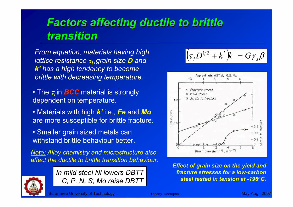
Factors affecting ductile to brittle Factors affecting ductile to brittle
transitiontransition
( ) βγτ si GkkD =+ ''21From equation, materials having high
lattice resistance ττττi ,grain size D and
k’ has a high tendency to become
brittle with decreasing temperature.
Effect of grain size on the yield and
fracture stresses for a low-carbon
steel tested in tension at -196oC.
• The ττττi in BCC material is strongly dependent on temperature.
• Materials with high k’ i.e., Fe and Mo
are more susceptible for brittle fracture.
• Smaller grain sized metals can
withstand brittle behaviour better.
Note: Alloy chemistry and microstructure also
affect the ductile to brittle transition behaviour.
In mild steel Ni lowers DBTT
C, P, N, S, Mo raise DBTT
Tapany Udomphol

Suranaree University of Technology May-Aug 2007
Intergranular fractureIntergranular fracture
Intergranular fracture with and without
microvoid coalescence.
• Intergranular failure is
a moderate to low energy
brittle fracture mode resulting
from grain boundary
separation or segregation of
embrittling particles or
precipitates.
• Embrittling grain
boundary particles are
weakly bonded with the
matrix, � high free energy
and unstable, which leads to
preferential crack
propagation path.
Intergranular fracture
with microvoid
coalescence
Intergranular fracture
without microvoid
coalescence
Tapany Udomphol

Suranaree University of Technology May-Aug 2007
Factors affecting modes of fractureFactors affecting modes of fracture
Metallurgical aspect
Temperature
State of stresses
(notch effect)
Strain rate
Brittle fracture Ductile fracture
Fine grained material
without GB particles.
Large grained materials
with GB particles.
Low temperature High temperature
Triaxial state of
stresses (notch effect)
Absence of the notch
High strain rate Low strain rate
Loading condition Hydrostatic pressure
(suppress crack initiation)
Tapany Udomphol

Suranaree University of Technology May-Aug 2007
Metallurgical aspect of fractureMetallurgical aspect of fracture
Microstructural features in metallic materials
• Microstructure in metallic materials are highly complex.
• Various microstructural features affect how the materials fracture.
• High strength materials usually possess
several microstructural features in order to
optimise mechanical properties by
influencing deformation behaviour /
fracture paths.
There are microstructural
features that can play a role in
determining the fracture path,
the most important are;
Second phase
Particles and precipitates
Grain size
Fibering and texturing
Tapany Udomphol

Suranaree University of Technology May-Aug 2007
State of stresses (notch effect)State of stresses (notch effect)
The difference in the state of stresses in the presence of a
sharp crack or notch affects fracture in materials.
A notch or a sharp crack increases the tendency
for brittle fracture in four important ways;
1) Producing high local stresses
2) Introducing a triaxial state of stresses
3) Producing high local strain hardening and cracking
4) Producing a local magnification to the strain rate.
Note: the notch also raises the plastic-constraint factor q,
which does not exceed the value of 2.75
Tapany Udomphol
Suranaree University of Technology May-Aug 2007
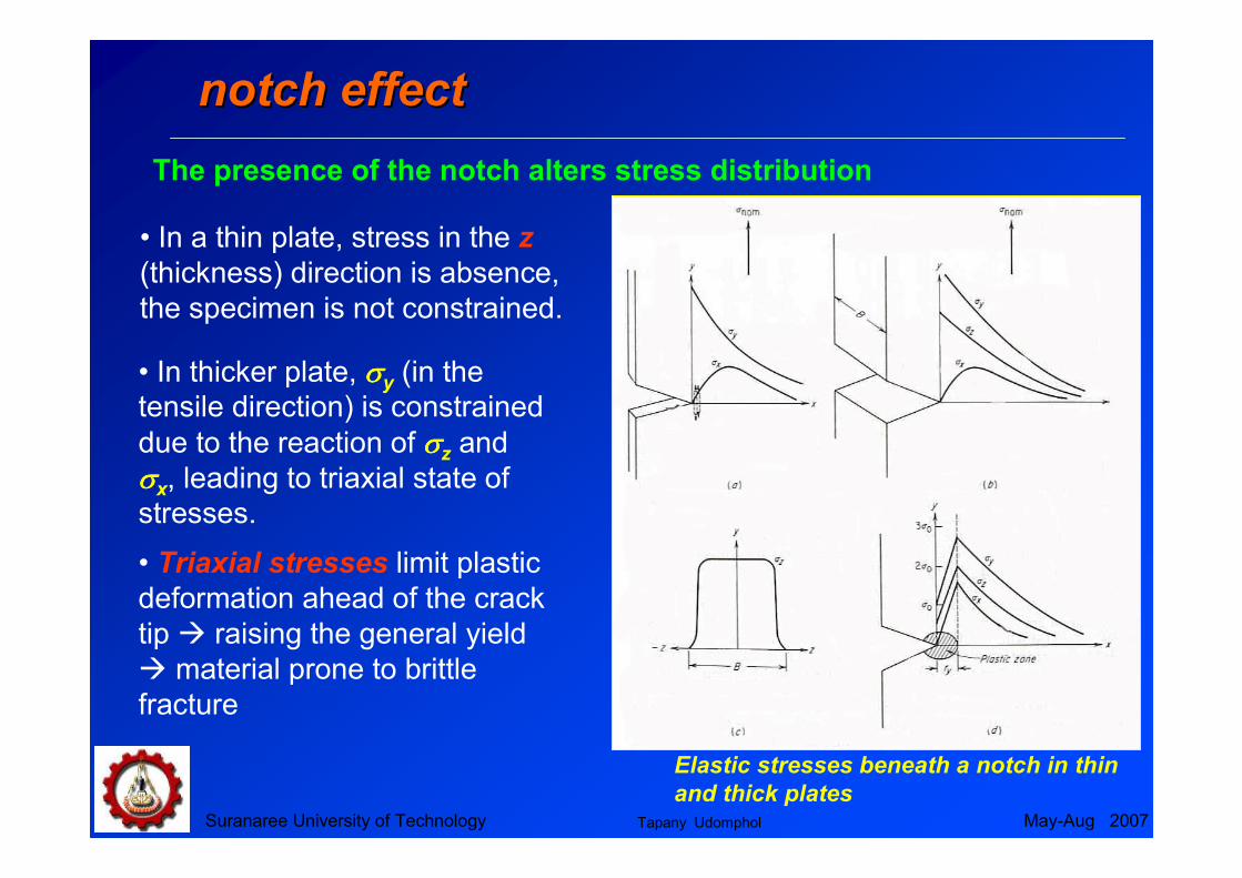
notch effectnotch effect
Elastic stresses beneath a notch in thin
and thick plates
• In a thin plate, stress in the z
(thickness) direction is absence,
the specimen is not constrained.
• In thicker plate, σσσσy (in the
tensile direction) is constrained
due to the reaction of σσσσz and
σσσσx, leading to triaxial state of
stresses.
• Triaxial stresses limit plastic
deformation ahead of the crack
tip � raising the general yield
� material prone to brittle
fracture
The presence of the notch alters stress distribution
Tapany Udomphol

Suranaree University of Technology May-Aug 2007
Effects of combined stress and Effects of combined stress and
hydrostatic pressure on fracturehydrostatic pressure on fracture
• Yielding under complex states of
stress is difficult to predict.
• Available data on ductile metals,
i.e., Al and Mg alloys and steel
indicate that the maximum-shear
stress criterion for fracture are in
the best agreement.
Proposed fracture criteria for biaxial
state of stress in ductile metal
Combined stress Hydrostatic pressure
• hydrostatic pressure is triaxial
compressive stress resist fracture
and increase ductility.
• Hydrostatic pressure exerts no
shear stress, it therefore does not
influence crack initiation but
affects crack propagation.
Effect of hydrostatic pressure on
ductility in tension
Tapany Udomphol
Suranaree University of Technology May-Aug 2007
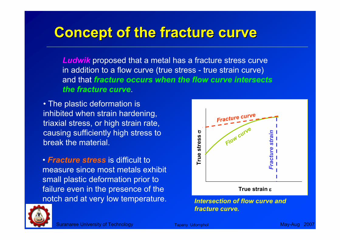
Concept of the fracture curveConcept of the fracture curve
True strain εεεε
Tru
e s
tress σσ σσ
Fracture curve
Fracture strain
Flow
curve
Intersection of flow curve and
fracture curve.
Ludwik proposed that a metal has a fracture stress curve
in addition to a flow curve (true stress - true strain curve)
and that fracture occurs when the flow curve intersects
the fracture curve.
• The plastic deformation is
inhibited when strain hardening,
triaxial stress, or high strain rate,
causing sufficiently high stress to
break the material.
• Fracture stress is difficult to
measure since most metals exhibit
small plastic deformation prior to
failure even in the presence of the
notch and at very low temperature.
Tapany Udomphol

Suranaree University of Technology May-Aug 2007
Notch effect on transition temperatureNotch effect on transition temperature
Temperature
Str
en
gth
Cleavage strength
qσσσσo
σσσσo
σσσσf
Transition temperature
in simple tension
Notch transition
temperature
Description of transition temperature
The fracture stress σσσσf is much less temperature sensitive
than the flow stress σσσσo.
• The σσσσo of the unnotched specimen
is lower than σσσσf at temperatures
above the transition temperature.
• The metal therefore deforms
plastically before fracture. Below the
transition temperature σσσσo > σσσσf, metal
fails without plastic deformation.
• The presence of the notch
raises the σσσσo by the plastic-
constraint factor q. This shifts
the transition temperature to the
right hand side.
Tapany Udomphol

Suranaree University of Technology May-Aug 2007
ReferencesReferences
• Dieter, G.E., Mechanical metallurgy, 1988, SI metric edition,
McGraw-Hill, ISBN 0-07-100406-8.
• Sanford, R.J., Principles of fracture mechanics, 2003, Prentice
Hall, ISBN 0-13-192992-1.
• W.D. Callister, Fundamental of materials science and
engineering/ an interactive e. text., 2001, John Willey & Sons, Inc.,
New York, ISBN 0-471-39551-x.
• Hull, D., Bacon, D.J., Introduction to dislocations, 2001, Forth
edition, Butterworth-Heinemann, ISBN 0-7506-4681-0.
• Smallman, R.E., Bishop, R.J., Modern physical metallurgy &
materials engineering, 1999, sixth edition, Butterworth-Heinemann,
ISBN 0-7506-4564-4.
Tapany Udomphol
Suranaree University of Technology May-Aug 2007
ReferencesReferences
• Cottrell, A.H., Theory of brittle fracture in steel and similar metals,
1958, Transactions of the metallurgical society of AIME, Vol. 212,
p. 192-203.
• Stroh, A.N., Advanced Physics, 1957. Vol 6: p. 418
Tapany Udomphol