07-08_ALP_GB_low
74
TECHNICAL MANUAL ALpINE FALL WINTER 07/08
-
Upload
free2terra5334 -
Category
Documents
-
view
85 -
download
7
Transcript of 07-08_ALP_GB_low

TECHNICALMANUAL
ALpINEFALL
WINTER 07/08

2007-2008
SalomonwarrantIES 3
ski-binding-snowblade
SKIlEnGtHSElECtIon 4
rEtaIl/rEntal Ski&ShortSki:technicalfeatureS 6 Binding:technicalfeatureS 16
Binding&SnowBlade: Mounting/Maintenance/repairS 17 adjuStMent 18
rEntal Binding:technicalfeatureS 36 Mounting 37 inSpection 39
maIntEnanCE/rEPaIrS Ski&SnowBlade 43 Binding 49
boot StandardBootnorMSdin/iSo5355 51 MeaSurer 52 advancedfittechnologyliner 53 BootconceptS 55 footanatoMyandfit 66
helmet Myperfectfit 70
pole technicalinforMation 72

warranties
For all other problems, contact the subsidiary Customer Service.
Salomon bootsSalomon alpine skis, Snowblade and boots are warranted for a period of 2 years from date of original purchase. To determine the period covered by the warranty, the customer has to show the sales receipt.The Salomon Snowblade warranty can only function if the customer presents the Snowblade unit to the dealer as it was sold (ski and binding). If not, the warranty cannot be honored.
Salomon Alpine skis and Snowblade warranty
The skis are covered for 1 year from the date of original purchase. The bindings are covered by a 5 years warranty from the date of original purchase.
Ski: if there is a problem that is covered by the warranty (breakage, pulled edge…) that occurs during the warranty period (1 year), Salomon will replace the Ski + Binding unit.
Binding: if there is a problem that is covered by the Salomon warranty (breakage, binding pulled-out…) that occurs during the warranty period (5 years), Salomon will replace the Ski + Binding unit, except if the damage concerns the brake or the AFD plate. In this case, Salomon will replace the defective part(s) with spare parts.
SKI problems which are not covered by the warranty
Problems Solutions
Bent skis Contact subsidiary for more information
Top surface Can be repaired
Tip protector Can be repaired with spare parts
Tail protector Cannot be repaired
Running surface Can be repaired
Binding pull-out Can be repaired with inserts
Pulled edge Can be repaired
This technical manual has been printed for use by Salomon Authorized dealers. It will provide you with information and clever techniques for the 2007/2008 product line to help you to meet the needs of your clients. The Salomon Customer Service Department is available for any additional information. Please keep a copy of this and earlier manuals on hand for quick, easy reliable reference for providing skiers with the highest standard of shop practice.
Salomon Helmets & Alpine PolesSalomon helmets and poles are guaranteed against defects in materials and manufacturing for a period of two years from their date of purchase*.This warranty only covers the defective components. Claims arising from improper storage of product, modification, abuse and normal wear are not covered by this warranty.This warranty applies only to products sold by an Authorized Salomon Dealer. For warranty service, present the defective helmet with the original sales receipt to your nearest Authorized Salomon Dealer.
Salomon’s only liability regarding this warranty will be to repair or replace the defective product with a model in an available version.Warning:• The Salomon helmets are designed only for
the following activities: ski, snowboard and skiboard (Snowblade®). They are not designed to be used on motorbikes or for other sports, mechanical or not.
• The Alpine Salomon poles are designed for cross-country or downhill skiing only, except for the adjustable poles that can be used for downhill skiing and hiking.
* This warranty may vary in some countries.
Salomon Alpine bindingsSalomon Alpine bindings, put on the market starting from 01.01.2001 – except for the Rental line – will benefit from a 5 years warranty instead of 2 years, starting from the date of the original purchase. To determine the period covered by the warranty, the customer must show the sales receipt.
The retailer must inform the customer of this.Complementary warranties may exist according to respective regional legislative systems.Salomon’s only liability as regards this warranty will be to repair or replace the defective product with a model or pair within the limits of available stock. These warranties cover skis, Snowblade, bindings against manufacturing defects.However, these warranties do not cover damage resulting from transport, handling, storage, failure by the client to follow the instructions for use, modification of the product or normal wear and tear. In case of damage to a product caused by an accident or misuse, please consult Salomon Customer Service for advice on possible repair or replacement.
INTERNATIONAL WARRANTY
�

WEIGHT
skilengthselection
For the Salomon skis, find the corresponding centimetre length for your weight
› Add to that number any additional length from the boxes below according to your ability, aggressiveness, the snow conditions you ski most of the time and the kind of skis you want to choose.
Corresponding
SKI LENGTH (cm) 140 145 150 155 160 165 170
Kilogramm < 47 48 - 52 53 - 58 59 - 65 66 - 73 74 - 82 83 >
TOTAL
This total centimetre length is a guide, your preferred length will be the ski closest to the recommended total.
ADULT
LEVEL
1. BEGINNER
You are skiing the first week
(rental skis)
- 20 cmDiscover firstski sensations
2. INTERMEDIATE
Able to ski most runs
in good conditions
- 5 cmPrefer moderate
speeds
3. ADVANCED
Able to ski all runs
in good conditions
+ 0 cmPrefer a variety
of speeds
4. EXPERT
Able to ski on all runs
in any conditions
+ 5 cmPrefer
high speeds
5. SPECIALIST
Able to ski on all runs in changing
conditions
+ 10 cmPrefer highest
speeds
+
TERRAIN
TARGET / KIND OF SKI
=�
Equipe 2V Race Equipe GC Race / GC Series Demo X2 / XR Aero X / GT+ / GTCrossmax W12 / V10 / V8 X Wing Gun / SPK / Foil / Thruster Scarlet / Mynx / Temptress Jewel
+ 4 cm
+
Equipe 3V Race Equipe SC Race Demo X3 / XT / X Lady Aero Ti / SCrossmax V6InstinctFlyer
- 1 cm
Most of the time off piste or on soft snow conditions > 60%
+ 5 cm
Most of the time on groomed piste or on hard snow conditions< 60%
+ 0 cm+

› Sk
i - B
iNDi
NG -
SNOW
BLAD
E
Ski length according to weight and height of children*
Example for 1080 FISH S = A 6 year old child weighting 25 kg (and measuring 120 cm), with intermediate skiing abilities, must choose a 111 cm ski with a "305" binding
JUNIOR
�
Recommendations of use of the skis according to the mass of skier
› To guarantee the sufficient parameters of safety (i.e. the resistance of the screws to wrench), the skiers must use skis, approximate with groups 1 to 4, in connection with the mass of the skiers**.
Group of ski
1 >65kg 1,2 ≤65kg 1,2,3 ≤45kg (1,2)3,4 ≤25kg
Mass of skier
** extract from NF ISO 8364 june 2007
* If weight is over 45 kg (100 Ibs), SALOMON strongly recommend to use an ADULT ski.

TECHNICAL FEATURESretail:
racing-carving-skier-X
�
retail
RA
CIN
G EquIPE 2V RACE 162 108 66 92 15,8 679 1800 46,5
• B75 • • •170 110 66 93 17,1 725 1900 47,3178 110 66 93 18,6 769 2020 48,8186 110 66 93 R ≥ 21m 811 2140 49,7
EquIPE 2V RACE 162 108 66 92 15,8 679 1780 46,5
• B75 • • •170 110 66 93 17,1 725 1880 47,3178 110 66 93 18,6 769 2000 48,8186 110 66 93 R ≥ 21m 811 2120 49,7
EquIPE GC RACE 154 115 67 96 12,5 637 1720
• B75 • •162 115 68 97 14,2 679 1820170 115 69 98 16,1 735 1920178 115 70 99 18,1 779 2040
EquIPE GC SERIES 154 117 66 98 11,4 654 1610
• B75 • •162 117 67 99 12,9 697 1690170 117 68 100 14,8 740 1780178 117 69 101 16,2 784 1910
EquIPE 3V RACE 150 117 66 102 10,6 625 1730 46,1
• B75 • • •155 118 66 102 11,4 655 1780 46,7160 119 66 103 11,7 684 1800 47,3165 120 66 103 12,5 714 1940 47,7
EquIPE 3V RACE 150 117 66 102 10,6 625 1710 46,1
• B75 • • •155 118 66 102 11,4 655 1760 46,7160 119 66 103 11,7 684 1780 47,3165 120 66 103 12,5 714 1920 47,7
EquIPE SC RACE 148 118 65 99 10,3 623 1610
• B75 • •156 120 65 100 11,3 666 1710164 122 65 101 12,2 716 1750172 124 65 102 13,1 754 1970
CA
RV
ING AERO X 154 115 67 96 12,5 637 1720
• B75 • •162 115 68 97 14,2 679 1820170 115 69 98 16,1 735 1920178 115 70 99 18,1 779 2040
AERO GT+ 154 117 66 98 11,4 654 1610
• B75 • •162 117 67 99 12,9 697 1690170 117 68 100 14,8 740 1780178 117 69 101 16,2 784 1910
AERO GT 154 117 66 98 11,4 654 1610
• B75 • •162 117 67 99 12,9 697 1690170 117 68 100 14,8 740 1780178 117 69 101 16,2 784 1910
AERO TI 130 108 69 91 9,8 541 1410
• B75 • •140 109 69 92 12 586 1510150 110 69 93 13,7 631 1610160 111 69 94 15,4 676 1710165 112 69 95 16,0 699 1760170 113 69 96 16,6 721 1810
AERO S 130 108 69 91 9,8 541 1410
• B75 • •140 109 69 92 12 586 1510150 110 69 93 13,7 631 1610160 111 69 94 15,4 676 1700165 112 69 95 16,0 699 1750170 113 69 96 16,6 721 1800
SK
IER
-X CROSSMAX W12 154 115 67 96 12,5 637 1780
• B75 • • •162 115 68 97 14,2 679 1880170 115 69 98 16,1 735 1980178 115 70 99 18,1 779 2100
CROSSMAX V10 154 117 66 98 11,4 654 1610
• B75 • •162 117 67 99 12,9 697 1690170 117 68 100 14,8 740 1780178 117 69 101 16,2 784 1910
CROSSMAX V8 154 117 66 98 11,4 654 1590
• B75 • •162 117 67 99 12,9 697 1670170 117 68 100 14,8 740 1760178 117 69 101 16,2 784 1890
CROSSMAX V6 130 108 69 91 9,8 541 1410
• B75 • •140 109 69 92 12 586 1510150 110 69 93 13,7 631 1610160 111 69 94 15,4 676 1710165 112 69 95 16,0 699 1760170 113 69 96 16,6 721 1810
MgC
Carb
on r
einf
orce
men
tFu
ll-Mo
noco
que
Mg
Lite
Sin
gle
Wal
lMo
noco
que
Lite
Singl
e Wa
llM
onoc
oque
Sin
gle
Wal
lMo
noco
que L
ite D
ouble
Wall
Mon
ocoq
ue D
oubl
e W
all
Mono
coqu
e Mg
Pow
erpl
ate
Prot
rak
Mg
SPAC
EFRA
ME
(ski +
inter
face +
bind
ing) M
SB 12
0 mm
(Racin
g mod
els +
914 or
Z12 o
r Z10)
Ski +
inte
rface
- (1/
2 PR
- g)
(*sk
i onl
y)
Wai
st
LENG
HTS
Tip
MID
SOL
E BO
OT (m
) WEIGHT THICKNESS
914
Z12
Ti
Z10
Ti
711
610
609
TZ5
SC
Z12
Z10
710
Ti
609
Ti
609
SC
BINDING OPTION
Prot
rak
Smar
trak
Gri
pSm
artr
ak G
rip
Plus
ITF
Loc
Tail
CONSTRuCTIONFIBERGLASS
RADI
uS (m
)SIDE CuT
Smar
trak
Pro
link
Smar
trak
Con
trol
Juni
or T
rack
SySTEM

› Sk
i - B
iNDi
NG -
SNOW
BLAD
E
7
Full
Wood
core
Pul
se P
ad
SPECIFIC FEATuRES
M Ch
assis
(72
wide
wai
st)
L Ch
assis
(75
wide
wai
st)
XL C
hass
is (8
5 wi
de w
aist
)XX
L Ch
assis
(95
wide
wai
st)
Dual
stanc
e: cla
ssic
/ pro
gres
sive
Tip
rive
tsTi
p &
tail
rive
tsTw
in T
ipPu
lse
Pad
TTFu
ll widt
h tota
l edg
e rein
force
ment
Forw
ard m
ounte
d bind
ing (+
8 mm
)Hy
brid
Tec
hnol
ogy
Edgy
mon
ocoq
ueFI
S No
rms
NORM
S
Juni
or n
orm
(scr
ew le
ngth
)
Juni
or F
IS N
orm
Met
alte
x
Diat
ex M
etal
Squa
rete
x
Pear
l
Tran
sluc
ent
Alut
ex
Flas
htex
Fint
ex
HMW
Gra
phite
HMW
tran
sluce
nt D
esig
ned
UHMW
Gra
phite
& D
esig
ned
UHM
W G
raph
iteIs
ocel
l Com
plex
Isoc
ell T
italli
um
Full
Wood
core
Lig
ht P
ulse
Pad
Isoc
ell W
oodc
ore
Full
Wood
core
Isoc
ell C
ompl
ex P
ulse
Pad
Isoce
ll Wo
odco
re P
ulse
Pad
BASE LAyOuT
Bar
codi
ngSi
ze c
olor
cod
ing
Rent
al to
p sh
eet
Tip
prot
ecto
r
Dura
ble
top
shee
t
Rein
forc
ed b
lack
bas
e
Wid
er e
dges
RENTALJR NORMCORE
Asym
etri
cal g
raph
ics
WSS
(Wom
en sp
ecifi
c side
cuts)
S Ch
assis
(70
wide
wai
st)
retail
RA
CIN
G EquIPE 2V RACE• • • • •
EquIPE 2V RACE• • • • •
EquIPE GC RACE• • • • •
EquIPE GC SERIES• • • • •
EquIPE 3V RACE• • • • • •
EquIPE 3V RACE• • • • • •
EquIPE SC RACE• • • •
CA
RV
ING AERO X
• • • • •AERO GT+
• • • • • •AERO GT
• • • • • • •AERO TI
• • • •
AERO S
• • • •
SK
IER
-X CROSSMAX W12• • • • •
CROSSMAX V10 • • • • • •
CROSSMAX V8• • • • •
CROSSMAX V6
• • •

TECHNICAL FEATURESretail:
allmountain-freestyle-demo
8
retail
AL
L M
Ou
NTA
IN XW LAB 198 140 107 120 33 925 2600* • •XW SANDSTORM(naked)
173 130 96 124 18,6 781 1970*
• •180 135 99 125 20,4 810 2050*187 135 101 126 22,2 852 2210*
XW FuRy(2bindingcombinations)
163 128 83 109 14,9 705 1890
• B90 B90 • • •170 128 84 110 16,6 743 2000177 128 85 111 18,4 778 2160184 128 86 112 20,4 817 2310
XW FuRy(naked)
163 128 83 109 14,9 705 1590*
• • •170 128 84 110 16,6 743 1700*177 128 85 111 18,4 778 1860*184 128 86 112 20,4 817 2010*
XW TORNADO 146 124 72 104 10,1 612 1570
• B80 • •154 124 73 105 11,4 654 1680162 124 74 106 12,9 697 1790170 124 75 107 14,5 740 1900178 124 76 108 16,2 784 2060
XW TORNADO(naked)
146 124 72 104 10,1 612 1270*
• •154 124 73 105 11,4 654 1380*162 124 74 106 12,9 697 1480*170 124 75 107 14,5 740 1600*178 124 76 108 16,2 784 1760*
X-WING 10 140 118 70 98 9,6 579 1700
• B80 • •150 118 71 99 11,7 629 1820158 118 72 100 13,2 671 1910166 118 73 101 14,9 714 1990174 118 74 102 16,7 757 2070
X-WING 8 140 118 70 98 9,6 579 1680
• B80 • •150 118 71 99 11,7 629 1800158 118 72 100 13,2 671 1890166 118 73 101 14,9 714 1970174 118 74 102 16,7 757 2050
X-WING 6 138 112 70 101 9,5 585 1460
• B80 • •146 113 70 102 10,6 625 1580154 114 70 102 11,7 665 1700162 115 70 103 12,9 705 1820170 116 70 103 14,2 745 1850178 117 70 104 15,4 785 2040
X-WING 4 138 112 70 101 9,5 585 1460
• B80 • •146 113 70 102 10,6 625 1580154 114 70 102 11,7 665 1700162 115 70 103 12,9 705 1820170 116 70 103 14,2 745 1850178 117 70 104 15,4 785 2040
FR
EE
ST
yL
E THE DuMONT (naked)
161 117 83 110 13,2 770 1500*
•171 117 83 110 15,4 824 1600*176 117 83 110 16,5 852 1700*181 117 83 110 17,5 879 1800*
TENEIGHTy GuN(naked)
164 130 94 123 15,5 750 / 730 1780*
• •174 130 96 124 18,6 802 / 782 1900*181 135 99 125 20,4 833 / 813 2100*188 135 101 126 22,2 875 / 855 2390*
TENEIGHTy SPK(naked)
168 110 77 102 19,1 807 1540*
• •180 113 79 106 21,2 865 1790*
TENEIGHTy FOIL(naked)
150 124 79 111 11,1 677 / 697 1350*
• •158 124 81 112 13,0 720 / 740 1480*166 124 83 113 15,2 763 / 783 1640*174 124 85 114 17,6 806 / 826 1770*182 124 87 115 20,4 849 / 869 1930*
TENEIGHTy THRuSTER (naked)
151 117 83 110 11,2 688 / 708 1340*
•161 117 83 110 13,2 739 / 759 1440*171 117 83 110 15,4 791 / 811 1540*181 117 83 110 17,5 843 / 863 1640*
TENEIGHTy FLyER(naked)
141 110 76 102 12,4 640 / 660 1150*
• •151 110 78 103 15,3 690 / 710 1290*161 110 80 104 18,7 740 / 760 1390*171 110 81 105 21 790 / 810 1700*
deMo
DEMO X2 162 108 66 92 15,8 679 1800
• B75 • •170 110 66 93 17,1 725 1900178 110 66 93 18,6 769 2020
DEMO X3(2bindingcombinations)
155 118 66 102 11,4 655 1780
•B75
• •160 119 66 103 11,7 684 1800 B75165 120 66 103 12,5 714 1940DEMO XR 154 117 66 98 11,4 654 1610
• B75 • •162 117 67 99 12,9 697 1690170 117 68 100 14,8 740 1780178 117 69 101 16,2 784 1910
DEMO XT 154 117 66 98 11,4 654 1610
• B75 • •162 117 67 99 12,9 697 1690170 117 68 100 14,8 740 1780
DEMO LADy 144 114 70 103 10.8 623 1500
• B75 • •154 116 70 104 12.1 675 1620159 117 70 105 12,6 704 1680
MgC
Carb
on r
einf
orce
men
tFu
ll-Mo
noco
que
Mg
Lite
Sin
gle
Wal
lMo
noco
que
Lite
Singl
e Wa
llM
onoc
oque
Sin
gle
Wal
lMo
noco
que L
ite D
ouble
Wall
Mon
ocoq
ue D
oubl
e W
all
Mono
coqu
e Mg
Pow
erpl
ate
Prot
rak
Mg
SPAC
EFRA
ME
(ski +
inter
face +
bind
ing) M
SB 12
0 mm
(Racin
g mod
els +
914 or
Z12 o
r Z10)
Ski +
inte
rface
- (1/
2 PR
- g)
(*sk
i onl
y)
Wai
st
LENG
HTS
Tip
MID
SOL
E BO
OT (m
) WEIGHT THICKNESS
914
Z12
Ti
Z10
Ti
711
610
609
TZ5
SC
Z12
Z10
710
Ti
609
Ti
609
SC
BINDING OPTION
Prot
rak
Smar
trak
Gri
pSm
artr
ak G
rip
Plus
ITF
Loc
Tail
CONSTRuCTIONFIBERGLASS
RADI
uS (m
)SIDE CuT
Smar
trak
Pro
link
Smar
trak
Con
trol
Juni
or T
rack
SySTEM

› Sk
i - B
iNDi
NG -
SNOW
BLAD
E
�
retail
AL
L M
Ou
NTA
IN XW LAB • • • • • •XW SANDSTORM(naked) • • • • • • • •XW FuRy(2bindingcombinations) • • • • • • •XW FuRy(naked) • • • • • • •XW TORNADO
• • • • • • • •XW TORNADO(naked) • • • • • • • •X-WING 10
• • • • • •X-WING 8
• • • • • •X-WING 6
• • • • • •
X-WING 4
• • • • •
FR
EE
ST
yL
E THE DuMONT (naked) • • • • • • •TENEIGHTy GuN(naked) • • • • • • • •TENEIGHTy SPK(naked) • • • • • • •TENEIGHTy FOIL(naked) • • • • • • •TENEIGHTy THRuSTER (naked) • • • • • • • • •TENEIGHTy FLyER(naked) • • • • •deMo
DEMO X2• • • • • •
DEMO X3(2bindingcombinations) • • • • • • •DEMO XR
• • • • • •DEMO XT
• • • • •DEMO LADy
• • • • • •
Full
Wood
core
Pul
se P
adSPECIFIC FEATuRES
M Ch
assis
(72
wide
wai
st)
L Ch
assis
(75
wide
wai
st)
XL C
hass
is (8
5 wi
de w
aist
)XX
L Ch
assis
(95
wide
wai
st)
Dual
stanc
e: cla
ssic
/ pro
gres
sive
Tip
rive
tsTi
p &
tail
rive
tsTw
in T
ipPu
lse
Pad
TTFu
ll widt
h tota
l edg
e rein
force
ment
Forw
ard m
ounte
d bind
ing (+
8 mm
)Hy
brid
Tec
hnol
ogy
Edgy
mon
ocoq
ueFI
S No
rms
NORM
S
Juni
or n
orm
(scr
ew le
ngth
)
Juni
or F
IS N
orm
Met
alte
x
Diat
ex M
etal
Squa
rete
x
Pear
l
Tran
sluc
ent
Alut
ex
Flas
htex
Fint
ex
HMW
Gra
phite
HMW
tran
sluce
nt D
esig
ned
UHMW
Gra
phite
& D
esig
ned
UHM
W G
raph
iteIs
ocel
l Com
plex
Isoc
ell T
italli
um
Full
Wood
core
Lig
ht P
ulse
Pad
Isoc
ell W
oodc
ore
Full
Wood
core
Isoc
ell C
ompl
ex P
ulse
Pad
Isoce
ll Wo
odco
re P
ulse
Pad
BASE LAyOuT
Bar
codi
ngSi
ze c
olor
cod
ing
Rent
al to
p sh
eet
Tip
prot
ecto
r
Dura
ble
top
shee
t
Rein
forc
ed b
lack
bas
e
Wid
er e
dges
RENTALJR NORMCORE
Asym
etri
cal g
raph
ics
WSS
(Wom
en sp
ecifi
c side
cuts)
S Ch
assis
(70
wide
wai
st)

10
TECHNICAL FEATURESretail:
women-rental
woMen
CA
RV
ING INSTINCT RuSH 144 112 63 93 10,3 614 1330
• B75 • •152 112 64 94 11,7 657 1430160 112 65 95 13,3 701 1580168 112 66 96 15,0 746 1660
INSTINCT FEVER 144 112 63 93 10,3 614 1320
• B75 • •152 112 64 94 11,7 657 1420160 112 65 95 13,3 701 1570168 112 66 96 15,0 746 1650
INSTINCT CHARM 130 108 69 91 9,8 549 1410
• B75 • •140 109 69 92 12 594 1510150 110 69 93 13,7 639 1600160 111 69 94 15,4 684 1700165 112 69 95 16,0 707 1750170 113 69 96 16,6 729 1800
AL
L M
Ou
NTA
IN JEWEL ORIGIN’S 154 124 73 105 11,4 662 1680B80 • •162 124 74 106 12,9 705 1740
170 124 75 107 14,5 748 1830JEWEL JADE 156 124 81 112 13,1 711 1850
• B90 • •164 124 83 113 15,2 754 1950172 124 85 114 17,7 797 2120180 124 87 115 20,4 840 2290
JEWEL TOPAz 140 118 70 98 9,6 587 1680
• B80 • •150 118 71 99 11,7 637 1800158 118 72 100 13,2 679 1890166 118 73 101 14,9 722 1970174 118 74 102 16,7 765 2050
JEWEL CRySTAL 138 112 70 101 9,5 593 1460
• B80 • •146 113 70 102 10,6 633 1580154 114 70 102 11,7 673 1700162 115 70 103 12,9 713 1820170 116 70 103 14,2 753 1850178 117 70 104 15,4 793 2040
JEWEL AMBER 138 112 70 101 9,5 593 1460
• B80 • •146 113 70 102 10,6 633 1580154 114 70 102 11,7 673 1700162 115 70 103 12,9 713 1820170 116 70 103 14,2 753 1850178 117 70 104 15,4 793 2040
FR
EE
ST
yL
E SCARLET(naked)
154 130 92 122 12,8 689 / 669 1670*
• •164 130 94 123 15,5 750 / 730 1780*174 130 96 124 18,6 802 / 782 1900*181 135 99 125 20,4 833 / 813 2100*
MyNX(naked)
150 124 79 111 11,1 677 / 697 1350*
• •158 124 81 112 13,0 720 / 740 1480*166 124 83 113 15,2 763 / 783 1640*174 124 85 114 17,6 806 / 826 1770*
TEMPTRESS (naked)
151 117 83 110 11,2 688 / 708 1340*
• •161 117 83 110 13,5 739 / 759 1440*171 117 83 110 15,4 791 / 811 1540*
rental
EquIPE GC RACE 154 115 67 96 12,5 637 1720
• • •162 115 68 97 14,2 679 1820170 115 69 98 16,1 735 1920178 115 70 99 18,1 779 2040
CROSSMAX W12 154 115 67 96 12,5 637 1780
• • • •162 115 68 97 14,2 679 1880170 115 69 98 16,1 735 1980178 115 70 99 18,1 779 2100
X-WING 10 140 118 70 98 9,6 579 1700
• • •150 118 71 99 11,7 629 1820158 118 72 100 13,2 671 1910166 118 73 101 14,9 714 1990174 118 74 102 16,7 757 2070
XW TORNADO 146 124 72 104 10,1 612 1570
• • •154 124 73 105 11,4 654 1680162 124 74 106 12,9 697 1790170 124 75 107 14,5 740 1900178 124 76 108 16,2 784 2060
CROSSMAX V800 154 117 66 98 11,4 654 1460
• • •162 117 67 99 12,9 697 1610170 117 68 100 14,8 740 1760178 117 69 101 16,2 784 1860
CROSSMAX V800(naked)
154 117 66 98 11,4 654 1180*
• •162 117 67 99 12,9 697 1330*170 117 68 100 14,8 740 1480*178 117 69 101 16,2 784 1580*
MgC
Carb
on r
einf
orce
men
tFu
ll-Mo
noco
que
Mg
Lite
Sin
gle
Wal
lMo
noco
que
Lite
Singl
e Wa
llM
onoc
oque
Sin
gle
Wal
lMo
noco
que L
ite D
ouble
Wall
Mon
ocoq
ue D
oubl
e W
all
Mono
coqu
e Mg
Pow
erpl
ate
Prot
rak
Mg
SPAC
EFRA
ME
(ski +
inter
face +
bind
ing) M
SB 12
0 mm
(Racin
g mod
els +
914 or
Z12 o
r Z10)
Ski +
inte
rface
- (1/
2 PR
- g)
(*sk
i onl
y)
Wai
st
LENG
HTS
Tip
MID
SOL
E BO
OT (m
) WEIGHT THICKNESS
914
Z12
Ti
Z10
Ti
711
610
609
TZ5
SC
Z12
Z10
710
Ti
609
Ti
609
SC
BINDING OPTION
Prot
rak
Smar
trak
Gri
pSm
artr
ak G
rip
Plus
ITF
Loc
Tail
CONSTRuCTIONFIBERGLASS
RADI
uS (m
)SIDE CuT
Smar
trak
Pro
link
Smar
trak
Con
trol
Juni
or T
rack
SySTEM

11
› Sk
i - B
iNDi
NG -
SNOW
BLAD
E
woMen
CA
RV
ING INSTINCT RuSH
• • • • • •INSTINCT FEVER
• • • • • •INSTINCT CHARM
• • • •
AL
L M
Ou
NTA
IN JEWEL ORIGIN’S• • • • • • •
JEWEL JADE• • • • • •
JEWEL TOPAz
• • • • • •JEWEL CRySTAL
• • • • • •
JEWEL AMBER
• • • • • •
FR
EE
ST
yL
E SCARLET(naked) • • • • • • • •MyNX(naked) • • • • • • •TEMPTRESS (naked) • • • • • • • •rental
EquIPE GC RACE• • • • • • •
CROSSMAX W12• • • • • • •
X-WING 10
• • • • • • • • •XW TORNADO
• • • • • • • • • • •CROSSMAX V800
• • • • • • • • • •CROSSMAX V800(naked) • • • • • • • • • •
Full
Wood
core
Pul
se P
ad
SPECIFIC FEATuRES
M Ch
assis
(72
wide
wai
st)
L Ch
assis
(75
wide
wai
st)
XL C
hass
is (8
5 wi
de w
aist
)XX
L Ch
assis
(95
wide
wai
st)
Dual
stanc
e: cla
ssic
/ pro
gres
sive
Tip
rive
tsTi
p &
tail
rive
tsTw
in T
ipPu
lse
Pad
TTFu
ll widt
h tota
l edg
e rein
force
ment
Forw
ard m
ounte
d bind
ing (+
8 mm
)Hy
brid
Tec
hnol
ogy
Edgy
mon
ocoq
ueFI
S No
rms
NORM
S
Juni
or n
orm
(scr
ew le
ngth
)
Juni
or F
IS N
orm
Met
alte
x
Diat
ex M
etal
Squa
rete
x
Pear
l
Tran
sluc
ent
Alut
ex
Flas
htex
Fint
ex
HMW
Gra
phite
HMW
tran
sluce
nt D
esig
ned
UHMW
Gra
phite
& D
esig
ned
UHM
W G
raph
iteIs
ocel
l Com
plex
Isoc
ell T
italli
um
Full
Wood
core
Lig
ht P
ulse
Pad
Isoc
ell W
oodc
ore
Full
Wood
core
Isoc
ell C
ompl
ex P
ulse
Pad
Isoce
ll Wo
odco
re P
ulse
Pad
BASE LAyOuT
Bar
codi
ngSi
ze c
olor
cod
ing
Rent
al to
p sh
eet
Tip
prot
ecto
r
Dura
ble
top
shee
t
Rein
forc
ed b
lack
bas
e
Wid
er e
dges
RENTALJR NORMCORE
Asym
etri
cal g
raph
ics
WSS
(Wom
en sp
ecifi
c side
cuts)
S Ch
assis
(70
wide
wai
st)

12
TECHNICAL FEATURESretail:
rental
rental
AERO TI R 130 108 69 91 9,8 536 1420
• • •140 109 69 92 12 586 1520150 110 69 93 13,7 636 1610160 111 69 94 15,4 687 1710170 113 69 96 16,6 740 1810
AERO S R 130 108 69 91 9,8 536 1410
• • •140 109 69 92 12 586 1510150 110 69 93 13,7 636 1600160 111 69 94 15,4 687 1700170 113 69 96 16,6 740 1800
AERO S R(naked)
130 108 69 91 9,8 536 1140*
• •140 109 69 92 12 586 1240*150 110 69 93 13,7 636 1330*160 111 69 94 15,4 687 1430*170 113 69 96 16,6 740 1530*
INSTINCT FEVER 800 130 108 69 91 9,8 544 1410
• • •140 109 69 92 12 594 1510150 110 69 93 13,7 644 1600160 111 69 94 15,4 695 1700170 113 69 96 16,6 748 1800
X-WING 800 140 118 70 98 9,6 579 1670
• • •150 118 71 99 11,7 629 1790158 118 72 100 13,2 671 1880166 118 73 101 14,9 714 1960174 118 74 102 16,7 757 2040
X-WING 800(naked)
140 118 70 98 9,6 579 1400*
• •150 118 71 99 11,7 629 1520*158 118 72 100 13,2 671 1610*166 118 73 101 14,9 714 1690*174 118 74 102 16,7 757 1770*
JEWEL AMBER 500 120 108 69 91 8,8 496 1300
• • •130 108 69 91 9,8 544 1410140 109 69 92 12 594 1510150 110 69 93 13,7 644 1600160 111 69 94 15,4 695 1700170 113 69 96 16,6 748 1800
JEWEL AMBER 500(naked)
120 108 69 91 8,8 496 1030*
• •130 108 69 91 9,8 544 1140*140 109 69 92 12 594 1240*150 110 69 93 13,7 644 1330*160 111 69 94 15,4 695 1430*170 113 69 96 16,6 748 1530*
X-WING 500 120 108 69 91 8,8 488 1430
• B80 • •130 108 69 91 9,8 536 1540140 109 69 92 12 586 1640150 110 69 93 13,7 636 1730160 111 69 94 15,4 687 1830170 113 69 96 16,6 740 1930
X-WING 500 120 108 69 91 8,8 488 1300
• • •130 108 69 91 9,8 536 1410140 109 69 92 12 586 1510150 110 69 93 13,7 636 1600160 111 69 94 15,4 687 1700170 113 69 96 16,6 740 1800
X-WING 500(naked)
120 108 69 91 8,8 488 1030*
• •130 108 69 91 9,8 536 1140*140 109 69 92 12 586 1240*150 110 69 93 13,7 636 1330*160 111 69 94 15,4 687 1430*170 113 69 96 16,6 740 1530*
XW FuRy JuNIOR L 140 107 65 88 13 585 1400 • • •150 108 65 89,5 14 635 1500XW FuRy JuNIOR M 120 106 65 86 9,5 485 1180 • • •130 106,5 65 87 11 535 1300XW FuRy JuNIOR S 90 100 65 83,5 5,5 365 830
• • •100 100 65 84 7 405 920110 102,5 65 86,5 7,5 450 940
XW JADE JuNIOR L 140 107 65 88 13 585 1400 • • •150 108 65 89,5 14 635 1500XW JADE JuNIOR M 120 106 65 86 9,5 485 1180 • • •130 106,5 65 87 11 535 1300XW JADE JuNIOR S 90 100 65 83,5 5,5 365 830
• • •100 100 65 84 7 405 920110 102,5 65 86,5 7,5 450 940
MgC
Carb
on r
einf
orce
men
tFu
ll-Mo
noco
que
Mg
Lite
Sin
gle
Wal
lMo
noco
que
Lite
Singl
e Wa
llM
onoc
oque
Sin
gle
Wal
lMo
noco
que L
ite D
ouble
Wall
Mon
ocoq
ue D
oubl
e W
all
Mono
coqu
e Mg
Pow
erpl
ate
Prot
rak
Mg
SPAC
EFRA
ME
(ski +
inter
face +
bind
ing) M
SB 12
0 mm
(Racin
g mod
els +
914 or
Z12 o
r Z10)
Ski +
inte
rface
- (1/
2 PR
- g)
(*sk
i onl
y)
Wai
st
LENG
HTS
Tip
MID
SOL
E BO
OT (m
) WEIGHT THICKNESS
914
Z12
Ti
Z10
Ti
711
610
609
TZ5
SC
Z12
Z10
710
Ti
609
Ti
609
SC
BINDING OPTION
Prot
rak
Smar
trak
Gri
pSm
artr
ak G
rip
Plus
ITF
Loc
Tail
CONSTRuCTIONFIBERGLASS
RADI
uS (m
)SIDE CuT
Smar
trak
Pro
link
Smar
trak
Con
trol
Juni
or T
rack
SySTEM

1�
› Sk
i - B
iNDi
NG -
SNOW
BLAD
E
rental
AERO TI R
• • • • • • •AERO S R
• • • • • • • •AERO S R(naked) • • • • • • • •INSTINCT FEVER 800
• • • • • • • • • •X-WING 800
• • • • • • • • • •X-WING 800(naked) • • • • • • • • • •JEWEL AMBER 500
• • • • • • • • • • •
JEWEL AMBER 500(naked)
• • • • • • • • • • •
X-WING 500
• • • • • • • • • •
X-WING 500
• • • • • • • • • •
X-WING 500(naked)
• • • • • • • • • •
XW FuRy JuNIOR L • • • •XW FuRy JuNIOR M • • • • •XW FuRy JuNIOR S
• • • •XW JADE JuNIOR L • • • •XW JADE JuNIOR M • • • • •XW JADE JuNIOR S
• • • •
Full
Wood
core
Pul
se P
ad
SPECIFIC FEATuRES
M Ch
assis
(72
wide
wai
st)
L Ch
assis
(75
wide
wai
st)
XL C
hass
is (8
5 wi
de w
aist
)XX
L Ch
assis
(95
wide
wai
st)
Dual
stanc
e: cla
ssic
/ pro
gres
sive
Tip
rive
tsTi
p &
tail
rive
tsTw
in T
ipPu
lse
Pad
TTFu
ll widt
h tota
l edg
e rein
force
ment
Forw
ard m
ounte
d bind
ing (+
8 mm
)Hy
brid
Tec
hnol
ogy
Edgy
mon
ocoq
ueFI
S No
rms
NORM
S
Juni
or n
orm
(scr
ew le
ngth
)
Juni
or F
IS N
orm
Met
alte
x
Diat
ex M
etal
Squa
rete
x
Pear
l
Tran
sluc
ent
Alut
ex
Flas
htex
Fint
ex
HMW
Gra
phite
HMW
tran
sluce
nt D
esig
ned
UHMW
Gra
phite
& D
esig
ned
UHM
W G
raph
iteIs
ocel
l Com
plex
Isoc
ell T
italli
um
Full
Wood
core
Lig
ht P
ulse
Pad
Isoc
ell W
oodc
ore
Full
Wood
core
Isoc
ell C
ompl
ex P
ulse
Pad
Isoce
ll Wo
odco
re P
ulse
Pad
BASE LAyOuT
Bar
codi
ngSi
ze c
olor
cod
ing
Rent
al to
p sh
eet
Tip
prot
ecto
r
Dura
ble
top
shee
t
Rein
forc
ed b
lack
bas
e
Wid
er e
dges
RENTALJR NORMCORE
Asym
etri
cal g
raph
ics
WSS
(Wom
en sp
ecifi
c side
cuts)
S Ch
assis
(70
wide
wai
st)

1�
› Sk
i - B
iNDi
NG -
SNOW
BLAD
E
1�
TECHNICAL FEATURESretail:
junior-shortskis
junior
EquIPE T 2V RACE 170 103 64 87 18,2 747 1555 49,8 • B75 B75 • •EquIPE T 2V RACE 142 97 64 83 14,7 601 1275 47,3
• B75 B75 • •149 99 64 84 15,3 638 1345 47,8156 99 64 84 17,0 673 1415 48,4163 101 64 86 17,6 710 1485 49,0
EquIPE T 2V RACE 135 95 64 81 14,0 567 1205 46,9 • B75 B75 • •EquIPE T 3V RACE 155 117 63 100 11.2 673 1615 49,0 • B75 B75 • •EquIPE T 3V RACE 140 114 63 99 9.2 609 1450 48,1 • B75 B75 • •150 116 63 100 10.4 656 1530 48,7EquIPE T 3V RACE 130 112 63 98 8 562 1320 47,5 • B75 B75 • •EquIPE 8 T POWERPLATE 140 107 65 88 13 585 1360 • •150 108 65 89,5 14 635 1460
EquIPE T L(naked)
140 107 65 88 13 585 1100* •150 108 65 89,5 14 635 1200*
EquIPE T M(naked)
120 106 65 86 9,5 485 880* •130 106,5 65 87 11 535 1000*
EquIPE T S(naked)
90 100 65 83,5 5,5 365 530* •100 100 65 84 7 405 620*110 102,5 65 86,5 7,5 450 640*
EquIPE T XS(naked)
70 91 65 75,5 4,5 300 400* •80 96,5 65 79,5 5 330 440*
XW FuRy JuNIOR L(naked)
140 107 65 88 13 585 1100* •150 108 65 89,5 14 635 1200*
JADE JuNIOR L(naked)
140 107 65 88 13 585 1100* •150 108 65 89,5 14 635 1200*
XW FuRy JuNIOR M(naked)
120 106 65 86 9,5 485 880* •130 106,5 65 87 11 535 1000*
JADE JuNIOR M(naked)
120 106 65 86 9,5 485 880* •130 106,5 65 87 11 535 1000*
XW FuRy JuNIOR S(naked)
90 100 65 83,5 5,5 365 530* •100 100 65 84 7 405 620*110 102,5 65 86,5 7,5 450 640*
JADE JuNIOR S(naked)
90 100 65 83,5 5,5 365 530* •100 100 65 84 7 405 620*110 102,5 65 86,5 7,5 450 640*
XW FuRy JuNIOR XS(naked)
70 91 65 75,5 4,5 300 400* •80 96,5 65 79,5 5 330 440*
JADE JuNIOR XS(naked)
70 91 65 75,5 4,5 300 400* •80 96,5 65 79,5 5 330 440*
TENEIGHTy FISH L(naked)
121 105 70 97 8.4 555 / 575 830*
• •131 105 72 98 10.6 605 / 625 940*141 105 74 99 13.3 655 / 675 1050*
TENEIGHTy FISH S(naked)
101 105 66 95 4,9 455 / 475 590*
• •111 105 68 96 6,5 505 / 525 710*
KITTEN L (naked)
121 105 70 97 8.4 555 / 575 830*
• •131 105 72 98 10.6 605 / 625 940*141 105 74 99 13.3 655 / 675 1050*
KITTEN S(naked)
101 105 66 95 4,9 455 / 475 590*
• •111 105 68 96 6,5 505 / 525 710*
ShortSkiS
CROSSMAX 120 RENTAL 120 112 76 102 8,9 541 1420 • B80 • •CROSSMAX 120 120 112 76 102 8,9 541 1470 • B80 • •AXESS 120 GIRL 120 112 76 102 8,9 541 1470 • B80 • •
MgC
Carb
on r
einf
orce
men
tFu
ll-Mo
noco
que
Mg
Lite
Sin
gle
Wal
lMo
noco
que
Lite
Singl
e Wa
llM
onoc
oque
Sin
gle
Wal
lMo
noco
que L
ite D
ouble
Wall
Mon
ocoq
ue D
oubl
e W
all
Mono
coqu
e Mg
Pow
erpl
ate
Prot
rak
Mg
SPAC
EFRA
ME
(ski +
inter
face +
bind
ing) M
SB 12
0 mm
(Racin
g mod
els +
914 or
Z12 o
r Z10)
Ski +
inte
rface
- (1/
2 PR
- g)
(*sk
i onl
y)
Wai
st
LENG
HTS
Tip
MID
SOL
E BO
OT (m
) WEIGHT THICKNESS
914
Z12
Ti
Z10
Ti
711
610
609
TZ5
SC
Z12
Z10
710
Ti
609
Ti
609
SC
BINDING OPTION
Prot
rak
Smar
trak
Gri
pSm
artr
ak G
rip
Plus
ITF
Loc
Tail
CONSTRuCTIONFIBERGLASS
RADI
uS (m
)SIDE CuT
Smar
trak
Pro
link
Smar
trak
Con
trol
Juni
or T
rack
SySTEM

1�
› Sk
i - B
iNDi
NG -
SNOW
BLAD
E
1�
TECHNICAL FEATURES
junior
EquIPE T 2V RACE • • • • •EquIPE T 2V RACE
• • • • •EquIPE T 2V RACE • • • • •EquIPE T 3V RACE • • • •EquIPE T 3V RACE • • • •EquIPE T 3V RACE • • • •EquIPE 8 T POWERPLATE
• • •EquIPE T L(naked) • • •EquIPE T M(naked) • • • •EquIPE T S(naked) • • •EquIPE T XS(naked) • • •XW FuRy JuNIOR L(naked) • • •JADE JuNIOR L(naked) • • •XW FuRy JuNIOR M(naked) • • • •JADE JuNIOR M(naked) • • • •XW FuRy JuNIOR S(naked) • • •JADE JuNIOR S(naked) • • •XW FuRy JuNIOR XS(naked) • • •JADE JuNIOR XS(naked) • • •TENEIGHTy FISH L(naked) • • •TENEIGHTy FISH S(naked) • • •KITTEN L (naked) • • •KITTEN S(naked) • • •ShortSkiS
CROSSMAX 120 RENTAL• • • • • •
CROSSMAX 120 • • •AXESS 120 GIRL • • •
Full
Wood
core
Pul
se P
ad
SPECIFIC FEATuRES
M Ch
assis
(72
wide
wai
st)
L Ch
assis
(75
wide
wai
st)
XL C
hass
is (8
5 wi
de w
aist
)XX
L Ch
assis
(95
wide
wai
st)
Dual
stanc
e: cla
ssic
/ pro
gres
sive
Tip
rive
tsTi
p &
tail
rive
tsTw
in T
ipPu
lse
Pad
TTFu
ll widt
h tota
l edg
e rein
force
ment
Forw
ard m
ounte
d bind
ing (+
8 mm
)Hy
brid
Tec
hnol
ogy
Edgy
mon
ocoq
ueFI
S No
rms
NORM
S
Juni
or n
orm
(scr
ew le
ngth
)
Juni
or F
IS N
orm
Met
alte
x
Diat
ex M
etal
Squa
rete
x
Pear
l
Tran
sluc
ent
Alut
ex
Flas
htex
Fint
ex
HMW
Gra
phite
HMW
tran
sluce
nt D
esig
ned
UHMW
Gra
phite
& D
esig
ned
UHM
W G
raph
iteIs
ocel
l Com
plex
Isoc
ell T
italli
um
Full
Wood
core
Lig
ht P
ulse
Pad
Isoc
ell W
oodc
ore
Full
Wood
core
Isoc
ell C
ompl
ex P
ulse
Pad
Isoce
ll Wo
odco
re P
ulse
Pad
BASE LAyOuT
Bar
codi
ngSi
ze c
olor
cod
ing
Rent
al to
p sh
eet
Tip
prot
ecto
r
Dura
ble
top
shee
t
Rein
forc
ed b
lack
bas
e
Wid
er e
dges
RENTALJR NORMCORE
Asym
etri
cal g
raph
ics
WSS
(Wom
en sp
ecifi
c side
cuts)
S Ch
assis
(70
wide
wai
st)

retail
1�
Brak
e
Arti
cle
num
ber
DIN
scal
e
Heig
ht (
in m
m)
Skie
r w
eigh
t (K
G)
Skie
r w
eigh
t (L
bs)
SCP
(Sal
omon
Con
trol
Ped
al)
Vert
ical
pro
gres
sive
piv
ot
Ski /
bin
ding
inte
rfac
e
Diag
onal
piv
ot
High
late
ral t
rans
mis
sion
Sim
ulta
neou
s w
ing
adju
stm
ent
Adju
stm
ent
rang
e (m
m)
Wei
ght
of 1
/2 p
air
(in
g)
Adju
stm
ent
rang
e (u
S si
zes)
Ti L
ine
Seni
or /
Jun
ior
norm
s
Auto
mat
ic w
ing
adju
stm
ent
Rem
ovab
le b
rake
BINDINGRANGE
pre-Mounted
K z12 Ti Smartrak control B80 788908 4-12 31,5 30-107 66-235 • • + Smartrak control • • 122 15 1311 Ti S
K z10 Smartrak control B80 788909 3-10 31,5 30-107 66-235 • • + Smartrak control • • 122 15 1585 S
K 710 Smartrak grip B80 788870 3-10 31,5 30-107 66-235 • • + Smartrak grip • • 123 15 1570 S
alacarteModelS
N 914 FIS 20 B80 788910 6-14 20 58-130 127-286 • • • • 122 15 1106 S
N STH 16 R90 788859 9-16 17,5 > 95 > 209 • +++ • • 19 2,5 1161 S
N STH 16 R100 788860 9-16 17,5 > 95 > 209 • +++ • • 19 2,5 1162 S
N STH 16 R130 788862 9-16 17,5 > 95 > 209 • +++ • • 19 2,5 1167 S
N STH 12 black/gold R90 543373 4-12 17,5 42-120 92-264 • ++ • • 19 2,5 1015 S
N STH 12 rust/khaki R90 788865 4-12 17,5 42-120 92-264 • ++ • • 19 2,5 1015 S
N STH 12 R100 554750 4-12 17,5 42-120 92-264 • ++ • • 19 2,5 1017 S
N STH 12 R130 554740 4-12 17,5 42-120 92-264 • ++ • • 19 2,5 1021 S
N z12 Ti B80 788899 4-12 16,5 42-120 92-264 • • + • • 28 3,5 857 Ti S
N z12 Ti B90 788900 4-12 16,5 42-120 92-264 • • + • • 28 3,5 858 Ti S
N z12 Ti B100 554898 4-12 16,5 42-120 92-264 • • + • • 28 3,5 860 Ti S
N z12 Ti B115 543309 4-12 16,5 42-120 92-264 • • + • • 28 3,5 863 Ti S
N z10 Ti B80 788902 3-10 16,5 30-107 66-235 • • + • • 28 3,5 857 Ti S
N z10 Ti white/silver soft B90 304360 3-10 16,5 30-107 66-235 • • + • • 28 3,5 858 Ti S
N z10 Ti black/gold soft B90 788903 3-10 16,5 30-107 66-235 • • + • • 28 3,5 858 Ti S
N z10 Fis 20 B80 788966 3-10 20 30-107 66-235 • • + • • 28 3,5 997 S
N 710 B80 554830 3-10 16,5 30-107 66-235 • • • • 28 3,5 959 S
N 710 B90 543310 3-10 16,5 30-107 66-235 • • • • 28 3,5 960 S
N 610 CP B80 788914 3-10 28,5 30-107 66-235 • Carve Plate • • 28 3,5 1077 S
N 610 black/red B80 554878 3-10 16,5 30-107 66-235 • • • 28 3,5 943 S
N 610 black/graphite B80 554875 3-10 16,5 30-107 66-235 • • • 28 3,5 943 S
junior
N Tz 5 red/black JR 788871 0,5-4,5 14 10-50 22-110 + • • 44 5,5 561 J&S
N Tz 5 blue alpine/white JR 304401 0,5-4,5 14 10-50 22-110 + • • 44 5,5 561 J&S
N Tz 5 magenta/silver JR 304407 0,5-4,5 14 10-50 22-110 + • • 44 5,5 561 J&S
N Tz 5 red/white JR 304404 0,5-4,5 14 10-50 22-110 + • • 44 5,5 561 J&S
N 608 JR 554866 2-7,5 16,5 22-85 55-187 • • • 28 3,5 920 S
N 607 white/blue angel B75 543368 2-7 16,5 22-80 55-180 • • • 28 3,5 919 S
N 607 black/silver B75 788913 2-7 16,5 22-80 55-180 • • • 28 3,5 919 S

› Sk
i - B
iNDi
NG -
SNOW
BLAD
E
WARNING
Be careful: do not use Snowblade® skiboards if you are shorter than 150 cm / 5 feet, and especially if you are a child under that height. Retailers and rental operators are obligated to communicate this information to their customers.
There are now two types of Snowblade® skiboards:
1. Release bindings: Snowblade® skiboards equipped with release bindings (ISO 9462) prioritizing release: a release binding is designed to open when forces applied to the leg when gliding or falling down are too high and can result injuries. release bindings do not guarantee release in all situations that may involve risks of injury or death, nor can the circumstances under which the binding releases be predicted. There is a risk of release when release is not desired or expected. There is also risk of no release when release is desired or expected. For these reasons, a release binding does not guarantee safety. Release bindings must be used with compatible ski boots according to ISO 5355 standards.
Choosing the best equipment:
Category 1: beginner through certain advanced skiboardersIf at least one of the following criteria applies to you, Salomon recommends that you use Snowblades® with release bindings:
- You have skied less than 7 days on any snow riding products (alpine skis, skiboards, snowboards)
- you do not jump or use terrain features such as half pipes, you glide beginning through advanced terrain (green circle through certain black diamond) in a soft manner or at moderate speed
- You do not regularly (1 to 2 hours per week) exercise or regularly participate in strenuous sports.
2. Non-release bindings: Snowblade® skiboards equipped with non-release bindings prioritizing attachment: CAUTION, non-release bindings are not designed to release during use. You should carefully consider the benefits and risks of release and non-release bindings before you choose which to use. Non-release bindings are primarily for use by experts and by advanced skiboarders who skiboard aggressively or use Snowblades® for jumping and terrain features –see the chart below. Non-release bindings help reduce the risk of inadvertent release during such activities.
Choosing the best equipment:
Category 2: certain advanced to expert skiboardersIf all the following criteria apply to you, Salomon recommends that you use Snowblades® skiboards with non-release bindings:
- you jump or you glide on steep terrain aggressively or at high speed or use terrain features such as half pipes.
- You feel confident on all types of terrain.
- You regularly (1-2 hours per week) exercise or regularly participate in strenuous sports and are in good physical condition.
- Skiboarding involves assuming risks, as with any snow riding activity. The risks you assume when you ski board include risks of injury and death. Snowblade® skiboards do not guarantee your safety or freedom from injury, whether equipped with release or non-release bindings. One type of skiboarder is not necessarily safer than another. Risks exist for skiboarders at all levels.
- Lessons: Salomon recommends that beginners take at least one lesson in order to receive the most benefit from Snowblade® and reduce your risks of injury.
- Height and age: If you are shorter than 150 cm / 5 feet and particularly if you are a child under 150 cm / 5 feet, you must not use Snowblade skiboards.
- If you are under 16 or over 55 years of age: The degree of ossification (bone density) for individuals under 16 and adults over 55 years of age may be different from usual rates and variable according to your health status. Thus, you must be in good physical condition before using Snowblade.
- Snowblade® skiboards are not designed for use back-country applications or deep snow conditions.
- Snowblade® skiboards are designed for use on groomed trails / pistes only.
- Any binding adjustment or repairs must be performed by an authorized Salomon dealer.
- Snowblade® skiboards with release bindings are designed to be used only with alpine ski boots.
- Snowblade® skiboards with non-release bindings may only be used with boots that have toe and heel lugs and that are adapted to the non-release binding system, such as alpine ski boots, snowboard carving boots or mountaineering boots.
MOUNTINGMAINTENANCE/REPAIRS
17
Warning: These recommendations and chart do not guarantee freedom from accidents or injuries while using Snowblade® skiboards. Accidents, injuries and even death are inherent risks of using any snow gliding equipment.

18
retailADJUSTMENT
1
2
3
4
5
6
7
8
9
10
SNOWBLADE BINDING/LARGE SIZES COMPATIBILITY
The Snowblade binding mounted on the retail products can accommodate boot sizes up to 30 Mondopoint (for traditional Alpine boots) and 29 Mondopoint (for specific Snowblade boots).To allow the Snowblade bindings to accommodate sizes up to 34 Mondopoint for the retail binding, Salomon offers a wire bail replacement kit.
This kit for large sizes consists of two black wire bails to replace the original gray toe bails. This kit is available as a spare part under the reference 891974.
Caution: mounting these specific wire bails for large sizes no longer allows you to use the conversion chart for adjusting the Snowblade binding. Be careful not to strip the screws when installing the longer bails!
For this reason, only use a manual scewdriver for loosening and tightening the screws.
Procedure for replacing the binding toe clips
- Put the toe clips in the open position by moving the central roller or the adjustment knob without going to the maximum (fig. 1).
- Loosen the 4 screws on the front part of the binding using a hand screwdriver (fig. 2).
- Pull the toe clip upward to lift up the front of the binding about 10 mm, and insert a screwdriver laterally between the board and the toe clip support piece (fig. 3).
- Stop pulling upward and now apply downward pressure, always acting on the same toe clip, so as to unsnap it from its support (fig. 4).
- Slide the toe clip forward and remove it (fig. 5).
- Take hold of the toe clip for large sizes and orient the toe clip + lever unit as to allow for it to be put on in the future (fig. 6).
- Place the new toe clip in its slot on the support and pull it upwards (while holding the front part of the binding to keep it from bending too much) to snap it on (fig. 7).
- Remove the screwdriver (fig. 8).
- Press down hard on the front part of the binding to make sure it is flat against the board (this procedure helps to make sure the toe clip is in the proper position on its support) (fig. 9). The toe clip support should be flat against the board.
- Tighten the 4 screws with a hand screwdriver using a 2,5 +/- 0,5 Nm torque (fig. 10). Follow the same procedure for the other binding.

1�
› Sk
i - B
iNDi
NG -
SNOW
BLAD
E
ADJUSTING THE SNOWBLADE
The Snowblade binding is designed to be used with alpine ski boots. Most Hiking and Snowboarding boots, whose outsoles conform to the ASTM, DIN, ISO norms, can also be used. You must clean the Snowblade binding and the boot sole before putting the boot in the binding.
Due to their shape (shell width, prominent shape) certain types of boots are unsuited for use with the snowblade binding. In this case, DO NOT uSE THE SNOWBLADE.
SNOWBLADE REPAIRS
If for any reason what so ever you need to dismount and/or remount the Snowblade binding, you must use a manual screwdriver only (2,5 +/- 0,5 Nm torque).
In case of a stripped screw, use the Snowblade repair drill bit (ref. 001090) and the traditional plastic repair plugs (ref. 000846). There is no jig to make this repair. However, the drill bit must be perpendicular to the surface of the ski. Make sure the repair plug is flush with the surface of the ski. If it isn’t, file it down to make it flush.
REPLACING THE SNOWBLADE LEASH
Spare part ref. S90405.
1. Remove the leash from the bail.
2. Put the replacement leash around the heel bail.
3. Put both parts of the rivet in the holes of the leash.
4. Squeeze both sides of the rivet together onto the leash (with pliers, vise...).
5. The rivet is in place when it no longer turns in the leash. Do not mount the rivet with a hammer.
STORING SNOWBLADE
If storing for an extended length of time, keep the heel bail in a high position to avoid any damage to the plastic parts. Store them in a dark, dry, ventilated area.
SNOWBLADE MAINTENANCE
The leash must never come in contact with the tuning machines. Roll up the leash and wedge it in the center of the binding with the bails closed. For maintenance, refer to ski maintenance paragraph.
REPLACING SNOWBLADE TIP PROTECTORS
SNOWBLADE 99
- Drill the rivets with a 4 mm diameter “carbide” drill bit.
- Put on the new tip protector by aligning the holes with the ones on the blade.
- Insert the male part of the rivet in the holes on the base side.
- Put the female part of the rivet in the holes on the top surface side.
- With multi-purpose pliers or a vise, squeeze both parts together making sure the rivet is flush with the tip protector. Do not use a hammer for this operation.
- The rivet is in position when there is no free play.
AxESS 120
1. Insert the tip protector on the ski.
2. Place the 2 screws in the 2 holes face the running base and screw on (1N.m).

ADJUSTMENT
retail
1
2
Good
3
Bad
A. Adjusting SpeedFit (Rental) bindingsUse the screw located at the rear end of the binding to make the adjustment (fig.1).1. Make the adjustment with a clean boot and no
snow on it.2. Using a power screwdriver or the drill that you
use for mounting bindings (4 Nm), separate the bails to allow for the placement of the boot.
3. Put the toe clip in the high position.4. Move the bails closer together by putting the
lever in a vertical position (fig.2). Important: do not put the bails in the riding position (fig.3), to prevent the risk of breakage.
5. Stop tightening the screw once the lever touches the end of the boot sole.
6. Check the adjustment with the boot in the binding: you should be able to pull the lever back with moderate pressure (3 daN).
7. Once the adjustment is finished, remove the boot and read the mark indicated on the scale under the boot platform.
8. On the other Snowblade, align the boot platform with the same mark.
9. Check by putting the other boot in the binding.
B. Snowblade Retail binding adjustment The Snowblade bindings have been designed to accommodate Alpine ski boots.1. Measure the boot sole length (in mm) with
the Synchro measurer (Ref. 001189).2. Move the metal bails by using the central
roller or the screw located at the back of the products with a manual screwdriver (5-6 Nm torque) to align the axis of the bail with the graduation of the plate that corresponds to the boot sole length in mm.
3. Check the proper adjustment by placing the boot in the binding (once the lever is closed, it should exert pressure on the front of the boot and the force to open the lever should be about 3 daN; if this is not the case, modify the adjustment).
20
Tools needed:RulerYellow Alpine binding grease: reference 000905 (see spare parts catalog).
1. Remove the defective screw2. Before mounting, put the grease (reference 000905) on both ends of the new screw.3. Put the screw in the 2 carriages: be careful not
to switch the front and rear carriages in relationship to the screw. (the rear carriage must be on the same side as the alu insert). Tighten the carriages on the screw sufficiently to make the mounting easier (fig.4).
4. Mount the screw / carriage unit on the frame of the binding (fig.5).
5. Adjust the axle of the rear carriage on the size 330 mm as described below (fig.6).
6. Using a ruler, measure the distance between the rear carriage and the plate as described below. This distance must be 5 mm.(fig.7).
7. Adjust the front carriage by tightening/ loosening it to get the same carriage/plate distance between front and back. (make sure you don’t change the rear carriage adjustment during this operation) (fig.8).
INSTRUCTIONS fOR REPLACING THE ADJUSTMENT SCREW ON THE RETAIL SNOWBLADE BINDING (Sf214)
Front carriage
Rear carriage (with leash)
The alu screw insert placed on the same side as the rear carriage
Grease present
4
5
6
8
Page 2 / 3
7

21
› Sk
i - B
iNDi
NG -
SNOW
BLAD
E
› Technical manuals for Skis and Bindings› Spare-parts catalogs› Release adjustment table (DIN chart)
+ skier type› Jigs (please consult spare-parts catalog for
different references)› Synchro measuring device ref. 001189› Salomon brake retainers ref. 000881› Electric drill› Drill bits (see on spare-parts catalog for
different models)› Adjustment tool (Salomon screwdriver)
ref. 000902› Power screwdriver with torque release› Posidrive® screwdriver 7mm - ref. 000862› Tap ref. 000816› Brace ref. 000817› Repair kit (2 extractor bits and repair plugs)
ref. 000878
› Grease ref. 000905› Glue ref. 000811› 4.5 diameter plastic plugs (different
references depending on the color - see spare-parts catalog)
› Specific adaptations: (for the references see spare-parts catalog)Brakes- carving (=long arms)- wide brakePlates
› For all other parts (such as AFD, housing, brakes, crews...), please consult your spare parts catalog.
PROPER PROCEDURES
Proper procedures to be used while mounting and adjusting Salomon bindings are the following steps.
› 1. Mounting bindings.› 2. Binding-to-boot adjustments.› 3. Release value selection and adjustment.› 4. Final checking visual and mechanical
inspections.› 5. Skier instruction and warning.
Important: before drilling the ski, it is important to determine that the boot you are using will be compatible with the binding. Only boots that conform with ASTM, DIN (German Industrial Norm), or ISO (International Standard Organization) boot sole standards should be used with Salomon bindings. A boot sole must also be flat and in good condition.
LIST‑Of‑TOOLS‑AND‑ACCESSORIES THAT‑ARE NECESSARY IN THE WORkSHOP
TECHNICAL DESCRIPTION
1. Height adjustment screw
2. Indicator
3. Release adjustment screw
4. AFD insert
5. Brake pad
6. Heel plate
7. Heel cup
8. Brake arms
9. Heel lever unit
10. Heel cup axis
11. Heel housing
12. Length adjustment
13. Mobil Plate SCP (Salomon Control Pedal)
Smartrak Prolink / Response / Control Smartrak Grip / Grip Plus
13
12
7
9
10
11
3
8
5
1 4
2
3
6
Powerplate
MOUNTING
retail
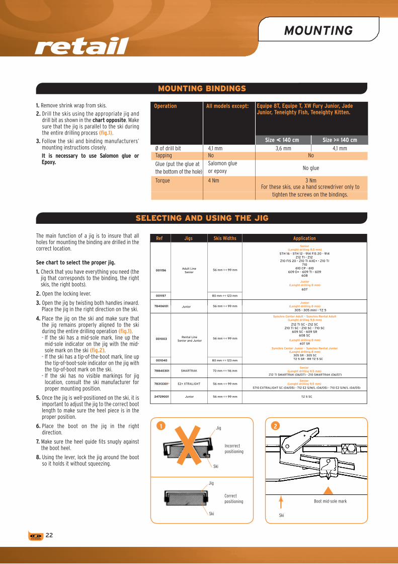
1. Remove shrink wrap from skis.2. Drill the skis using the appropriate jig and
drill bit as shown in the chart opposite. Make sure that the jig is parallel to the ski during the entire drilling process (fig.1).
3. Follow the ski and binding manufacturers’ mounting instructions closely.It is necessary to use Salomon glue or Epoxy.
The main function of a jig is to insure that all holes for mounting the binding are drilled in the correct location.
See chart to select the proper jig.
1. Check that you have everything you need (the jig that corresponds to the binding, the right skis, the right boots).
2. Open the locking lever.
3. Open the jig by twisting both handles inward. Place the jig in the right direction on the ski.
4. Place the jig on the ski and make sure that the jig remains properly aligned to the ski during the entire drilling operation (fig.1).- If the ski has a mid-sole mark, line up the
mid-sole indicator on the jig with the mid-sole mark on the ski (fig.2).
- If the ski has a tip-of-the-boot mark, line up the tip-of-boot-sole indicator on the jig with the tip-of-boot mark on the ski.
- If the ski has no visible markings for jig location, consult the ski manufacturer for proper mounting position.
5. Once the jig is well-positioned on the ski, it is important to adjust the jig to the correct boot length to make sure the heel piece is in the proper position.
6. Place the boot on the jig in the right direction.
7. Make sure the heel guide fits snugly against the boot heel.
8. Using the lever, lock the jig around the boot so it holds it without squeezing.
Operation All models except:
Size < 140 cm Size >= 140 cm Ø of drill bit 4,1 mm 3,6 mm 4,1 mm Tapping No No
Glue (put the glue at Salomon glue No glue
the bottom of the hole) or epoxy
Torque 4 Nm 3 Nm For these skis, use a hand screwdriver only to
tighten the screws on the bindings.
2
Ski
Boot mid-sole mark
1 Jig
Ski
Jig
Ski
Incorrect positioning
Correct positioning
MOUNTING BINDINGS
SELECTING AND USING THE JIG
22
Equipe 8T, Equipe T, XW Fury Junior, Jade Junior, Teneighty Fish, Teneighty Kitten.
Ref Jigs Skis Widths Application
001156 Adult Line
Senior 56 mm <-> 99 mm
Senior (Lenght drilling 9,5 mm)
STH 16 - STH 12 - 914 FIS 20 - 914 Z12 TI - Z12
Z10 FIS 20 - Z10 TI AXE+ - Z10 TI 710
610 CP - 610 609 D+ - 609 TI - 609
608
Junior (Lenght drilling 8 mm)
607
001157 80 mm <-> 123 mm
78406101 Junior 56 mm <-> 99 mmJunior
(Lenght drilling 8 mm)305 - 305 mini - TZ 5
001003 Rental Line
Senior and Junior 56 mm <-> 99 mm
Synchro Center Adult - Synchro Rental Adult (Lenght drilling 9,5 mm)
Z12 TI SC - Z12 SC Z10 TI SC - Z10 SC - 710 SC
609 SC - 609 SR 608 SC
(Lenght drilling 8 mm) 607 SR
Synchro Center Junior - Synchro Rental Junior (Lenght drilling 8 mm)
305 SR - 305 SC TZ 5 SR - RR TZ 5 SC 001040 80 mm <-> 123 mm
78840301 SMARTRAK 70 mm <-> 116 mm Senior
(Lenght drilling 9,5 mm)
(Lenght drilling 9,5 mm)
Z12 TI SMARTRAK (06/07) - Z10 SMARTRAK (06/07)
78313301* E2+ XTRALIGHT 56 mm <-> 99 mm Senior
S710 EXTRALIGHT SC (04/05) - 712 E2 S/M/L (04/05) - 710 E2 S/M/L (04/05)
TZ 5 SC 24729001 Junior 56 mm <-> 99 mm

› Sk
i - B
iNDi
NG -
SNOW
BLAD
EGLUE
Glue must be used when inserting binding screws to:- lubricate the screw during insertion,- create a watertight seal.
Place a drop of glue on the surface of each hole.
Caution: Salomon strongly recommends its own glue for Salomon skis.
1. Follow the recommendations of the ski manu-facturer for drilling and tapping. When in doubt about the ski’s core composition, select a 3.6 mm diameter bit, and drill one hole to see if any metal comes in contact with the bit. If contact is made with metal, re-drill with a 4.1 mm bit.
2. Drill through the jig’s proper bushings applying moderate downward pressure on the drill. Make sure that the countersink bevel on the drill bit has properly deburred the hole.
3. After drilling, turn the ski over and hit the base several times with the palm of your hand to remove any debris from the drilled holes.
DRILLING JuNIOR SKIS- Use a 9.5 mm length drill bit when mounting
Z10 TI - Z10 TI SC - Z10 SC - Z10 TI AXE+ - Z10 - Z10 FIS 20 - 710 - 710 SC - 610 - 610 CP - 609 D+ - 609 - 609 SR - 609 SC - 608 - 608 SC bindings. These models use the same screws as the Salomon adult models and should be drilled and tapped accordingly.
- Use an 8 mm length drill bit to mount the 607 - 607 SR - 305 SC - 305 SR - 305 - 305 Mini - TZ 5 - TZ 5 SC - TZ 5 SR - RR TZ 5 SC.
- Whenever junior bindings are mounted on adult skis, there is an increased possibility for binding pull-out due to poor screw retention. The penetration depth of junior screws into the ski core is only 6 mm.If necessary, use adult screws and drill bits to penetrate any mounting platform.(For bindings mounted with adult binding screws, the penetration depth is the same.)
- You must drill a hole deep enough to accommodate the screw length you are using or damage to the ski base may result.
TAPPING
Tapping is usually done when the binding screw will come into contact with metal or in the following cases:- the material is too hard for a screw,- when the screw insertion would distort or
stress the material holding the screw,- when recommended by the ski manufacturer.Failing to tap when necessary can result in top skin or sidewall delamination, broken screws or damage to the ski core.
To use a Salomon tap and brace:1. Position the brace so that the tap goes
straight into the drilled hole.2. Apply only enough pressure on the brace to
start the tap. The tap is a self-cutting tool and you have only to turn the brace for the tap to cut its own way into the core.
3. Make 3 1/2 turns.4. After tapping, turn the ski over and hit the
base several times with the palm of your hand to remove any shavings from the hole.
Length
Diameter
Drill bit length
Skis Diameter Length Reference Aspect
Junior
4,1 mm 8 mm 000813
3,6 mm 8 mm 000814
Adult
4,1 mm 9,5 mm 000893
3,6 mm 9,5 mm 000892
DRILLING
MOUNTING
Follow the mounting procedure and also refer to the section “Special cases in mounting”.A Posidrive® n° 3 screwdriver, not a Phillips, must be used to mount Salomon bindings. Consult the Salomon Spare Parts Catalog for reference on Salomon screws. Caution: if a power screwdriver is used, adjust the clutch for the appropriate ski core cons-truction (4 Nm maximum) to avoid stripping the threads. It is advisable to hand check each screw after mounting.
2�

retail
TOE PIECE 1. Before to mount the foward base sub-unit, Break
the small part under the toe (photo A0).2. Position the toe piece over the drilled holes
(photo A1).3. Use a crisscross screwing pattern and insert
each screw until nearly seated. Do not tighten until all screws are in place (photo A2).
4. The base plate of the AFD should be flush with the base plate of the toe piece.
quADRAX TOE1. First, pull the center mounting hole sliding
track out from the binding far enough to insert the screw into the ski (photo A3).
2. Tighten the screw until it is firmly seated and hold the toe to keep it from rotating on the ski.
3. Next, slide the toe piece towards the seated center screw until the two rear screws align with their respective holes (photo A4).
4. Tighten the rear screws until they are firmly seated.
5. Make sure the toe is screwed tightly to the ski. The top of each screw should be flush with the base plate.
HEEL PIECEPlace the heel over the prepared holes and tighten the screws using a crisscross screwing pattern.
SKI BRAKE1. Do not compress the ski brake before
installing it.2. Place the two metal tabs on the front of the
brake into the slots in the heel base plate (fig. A5).
3. Rotate the rear of the brake downwards to start the screw in the track.
4. Tighten screws with a handscrewdriver (4 Nm maximum) (photo A6).Note: The brake can be removed to facilitate ski maintenance.To remove it: turn the center screw toward the left and remove the brake.
A1
A0
RECOMMENDATIONS fOR CARVING BRAkES
*Weight and height indicated for one half unit for skiing = 1 ski + 1 binding + 1 interface.
Carving Brakes ref. 78576001-78574601-78574701 => Length Arms = 115 mm
*Maximum weight authorized 3,800 kg *Maximum height authorized 65 mm *Minimum height authorized 48 mm
A2
A3 A4
A5 A6
MOUNTING
INSTALLATION
SPECIAL BRAkES
Special brakes are available- Carving brakes - long arms => length Arms =115 mm- large brakesSee spare-parts catalog.
2�

2 3
4 6
7
5
8 9
NO OK
To be mounted by a Salomon Authorized dealer only.
› Sk
i - B
iNDi
NG -
SNOW
BLAD
E
MOuNTING1. Insert the Thin Plate in the seating ahead the
plate (fig. 1).2. Place it correctly with a rotational motion
(fig. 2).3. From the rear, slide the Toe piece on the
interface until it corresponds with or is just above your boot sole length using the manual lock to authorize the sliding (fig. 3 & 4).
4. From the rear, slide the Heel piece on the interface until it corresponds with or is just above your boot sole length using the manual lock to authorize the sliding (fig. 5).
5. Mount the Brake following the usual procedure (fig. 6).
ADJuSTING EXAMPLE6. Identify the length of the boot.7. If you have boot sole L 306 mm, adjust the Toe
on the 308 mm mark. The range in this case is 301 mm to 308 mm
(fig. 7).8. If you have chosen the L 306 mm, adjust the
Heel piece on the 312 location. The range in this case is 305 mm to 312 mm
(fig. 8).9. Step in the boot and check forward pressure
(fig. 9). The arrow on the housing must be within the
scribed area.
CONTENTS OF THE BOX› 2 Toes mounted on a sliding part› 2 Heels mounted on a sliding part› 2 Brakes› 2 Thin Plates› 1 Notice
SPECIAL CASES IN MOUNTING & ADJUSTING
SMARTRAk PROLINk / RESPONSE / CONTROL
MOUNTING SMARTRAk PROLINk / RESPONSE / CONTROL
2�
1

retail
2�
SPECIAL CASES IN MOUNTING & ADJUSTING
To be mounted by a Salomon Authorized dealer only.
MOuNTING AND AJuSTING1. Insert the Thin Plate in the seating ahead the
plate (fig. 1).2. Place it correctly with a rotational motion
(fig. 2).3. Identify the length of the boot.4. Identify the letter that corresponds your sole
length. (If you are between two, choose the higher one) (fig. 3).
5. Screw the center mounting track to this letter. (4Nm Torque) (fig. 4).
Mount the Toe piece as usual (fig. 5).6. From the rear, slide the Heel piece on the
interface using the manual lock to authorize the sliding (fig. 6).
7. Mount the Brake following the usual procedure (fig. 7).
8. Position your boot in the toe and slide the heel until it touches the boot (fig. 8).
9. Step in the boot and check forward pressure (fig. 9).
The arrow on the housing must be within the scribed area
Info: The rear N° is an indication for a quick adjustment of the second ski (fig. 10).
CONTENTS OF THE BOX› 2 Toes mounted on a sliding part› 2 Heels mounted on a sliding part› 2 Brakes› 2 Thin Plates› 1 Notice
SMARTRAk GRIP / GRIP PLUS
MOUNTING SMARTRAk GRIP / GRIP PLUS
7 8
5
10
4
6
9
NO OK
21 3

› Sk
i - B
iNDi
NG -
SNOW
BLAD
E
S914 LAB ON ZZ SPEED 2
ZZ SPEED 2 PLATE
27
To be mounted by a Salomon Authorised dealer only. Not compatible with Flat skis. To be mounted only on zz Interface.
CONTENTS OF THE BOX> 2 Toes S914 LAB ZZ> 2 Heels S914 LAB ZZ> 2 Brakes R75 L DG x 110 mm
(Ref Spare Parts: 78575401)> 2 Set Cross bar for Toes> 2 Yellow Lifters for Toes 2 mm> 2 Yellow Lifters for Heels 2 mm> 2 Black Lifters for Toes 1 mm> 2 Black Lifters for Heels 1 mm> 2 Yellow Web Housing (Central Plate)> 1 Mounting Notice
TOOLS NEEDED FOR MOuNTINGOnly a Screwdriver.
MOuNTING THE BINDING1. Break the Yellow Web Housing at the correct
length boot (fig. 1 & 2).2. Slide the Web Housing on the Web (fig. 3).3. Put the Web Housing under the Toe (fig. 4).4. Put the Cross bar under the Toe (fig. 5 & 6).5. Add the Lifters under the Heel and the Toe
to have the correct height (fig. 7 & 8).6. Put the Set Heel+Toe on the Interface at the
position (fig. 9).
7. Tighten the Toe (fig. 10 & 11).8. Slide the heel to have 3mm between the track and the rear heel (fig. 12).9. Tighten the Heel (fig. 13).10. Verify the height (fig. 14).11. Mount the Brake following the usual
procedure.12. Step in the boot (fig. 15).13. Adjust the forward pressure to have 3 mm
under the screw head (fig. 16 & 17).
don'taddmorethan5mmoflifters.
18.5 + A + ? = FIS Label
50 / 55mm = FIS Label

SPECIAL CASES IN MOUNTING
retail
28
1. Toe piece mounting:• Place the toe, mounted on the sliding plate, in front of the track and slide it until it stop.• Depress the manual adjustment button (located on the front of the toe) and slide the toe all the way back (fig. C).• Slide the indicator forward and clip it on the sliding plate (see picture below) either manually or with a flat Salomon screwdriver (ref. 000902) (fig. D).2. Heel piece mounting:• Place the heel a the rear of the sliding plate and slide it until it stops (fig. E).3. Brake mounting following the usual procedure.
ADJuSTMENT1. Toe piece adjusting:Hold the toe and depress the manual toe adjustment button. The toe is free to move and can be adjusted in function of the boot sole length: • 260-279mm• 280-295mm• 296-307mm• 308-319mm• 320-335mm• 336-351mm• 352-360mm
2. Heel piece adjusting following the normal procedure.
3. To take the toe off the track:• Place the toe on the position 260-279 of the position indicator.• Unclip the position indicator with a flat Salomon screwdriver (fig. F).• Depress the manual toe adjustment button. This way, the toe can slide forward off the track.
DC
F
G
E
MOUNTING ITf PLATE
POWERPLATE JUNIOR INTERfACE
Compatible with quadrax bindings (all range) and driver binding range 04-05 only (fig. G).
MOuNTINGAccording to the boot sole length selected, tighten the screws on the toe and heel pieces (4Nm torque) in the corresponding position on junior interface:• 253-281mm• 273-301mm• 293-321mm• 313-341mm• 333-361mm• 353-381mm
Mount the brake following the usual procedure.

› Sk
i - B
iNDi
NG -
SNOW
BLAD
E
2�
SPECIAL CASES IN MOUNTING
TZ 5 ‑ 305 ‑ 305 MINI
They should never be used with boot soles longer than 304 mm or on skis longer than 140 cm (Junior ski norm).
1. Check the manual lock of the toe piece is totally opened and remove the brake lock from the brake (fig. 1).
2. From the front, slide the toe piece on the interface until it corresponds with or just above your boot sole length and close the manual lock (fig. 2 & 3).
3. From the rear, slide the heel piece on the heel track until it corresponds with or just above your boot sole length using the manual lock to autorize the sliding (fig. 2 & 3).
Caution : check the manual lock of the toe piece is closed (fig. 4).
JUNIOR TZ 5 SC RANGE 07
CARVING BRAkES
The Salomon carving brakes were designed to be mounted on skis pre-mounted with plates or for skiers who want to add one or more plates between their skis and bindings. See brake recommendation.
fAT SkIS
Refer to the Spare Parts catalog to know which brakes to use according to the different ski widths and binding models.Use the following jigs to drill fat skis for Salomon bindings:- ref. 001157 jig for adult retail bindings- ref. 001040 drilling template for the rental
bindings Synchro Center and Synchro Rental.
The reversible pads allow the jig to adapt to different ski widths (fig. 5):- put the thinner side of the pads on the inside
of the jig to drill skis that are 98 - 124 mm wide (fig. 6a),
- put the thinner side of the pads on the outside to drill skis that are 80 - 106 mm wide (fig. 6b),
- the pads should be mounted non symmetrically for skis that are 89-115 mm wide and allow the binding to be off-centered 4.5 mm laterally on the ski (fig. 6c).
Procedure for changing the pads to the other side:1. Pull the pad off the arm of the jig.2. Change the pad to the desired position.3. Insert the pad into the arm of the jig.
5
6
2a
2b
2c
7
4. Repeat this procedure:- On the other 3 arms for mounting the
bindings symmetrically.- On the other arm on the same side for a
dissymmetrical mounting (fig. 7).Before drilling, make sure it is off-centered on the proper side of the ski.If so, reverse the positions of the 4 pads for drilling the other ski.
1
2
3
4

retail
�0
ADJUSTING
WING ADJUSTMENT
TOE HEIGHT ADJUSTMENT
fORWARD PRESSURE ADJUSTMENT
1. Manual adjustment (fig. A1): only one adjust-ment screw, which is located on the left side of the toe piece.
- Place the boot in the binding (closed position).- Loosen the micrometric screws to loosen the
wings.- Check that the tip of the boot sole is flush
against the butt plate (fig. A2).This contact is made when the boot has lateral play. Do not over tighten, the boot may no longer be centered.
2. Automatic adjustment: the wings on the toe cup are self-adjusting.
OK NOK
A1 A2
C1 C2
Once the binding has been mounted, it is necessary to make the proper binding-to-boot adjustments.
All Salomon bindings may be closed manually by simply lifting the heel lever.
Adjustments must be re-checked every time boots are changed. Use the following procedure.
Models
Wing Toe height adjustment adjustment
simultaneous manual
0 mm
automatic automatic
914
Tz 5to
z12
B1
B2
- With the boot in the binding, raise the toe by turning the adjustment screw, located on top of the toe piece, counter clockwise.
- Pull the boot back to create a gap between the boot sole and the binding AFD.
- Lower the toe height by turning the adjustment screw clockwise to obtain the recommended gap (see the following chart (fig. B1-B2).
- For models with automatic wing and automatic height adjustments: make forward pressure adjustment only. See instructions in following chapters.Note: Always check the forward pressure after making toe adjustments.
With adjustment tab (fig. C1-C2).With the boot in the binding (closed position), make sure the arrows on the adjustment tab line up within the scribed area at the end of the heel housing. If this adjustment is incorrect, remove the boot from the binding, lift the adjustment tab using a Salomon adjustment tool to slide the heel into the desired position. Remove the screwdriver. Re-insert the boot to check the adjustment.
With screw adjustment: STH 12 & 16 models (fig. D1).With the boot in the binding (closed position), adjust the forward pressure to align the top of the head screw with the back of the heel track.
D1

› Sk
i - B
iNDi
NG -
SNOW
BLAD
E
�1
NB: skiers who have had a satisfactory experience with lower adjustment values can request them.
ADJUSTMENT PROCEDURE
The release setting adjustment is obtained by using the adjustment cap or adjustment screws.The release setting is visible on the indicator. Adjust the toe piece and heel piece to the same settings. It is highly recommended to use a measuring device to check the release torque (see ISO 11088).Release value selection and adjustmentThe release settings must be used by the tech-nician to determine the appropriate adjustment for each skier, which conforms to the following norms: ISO 11088, ASTM F 939, ASTM F 1063, and AFNOR FD S 52-448 (documentation fascicle).
SKIER CLASSIFICATION This classification has to be determined by a dialogue between the skier and dealer, which helps to take into account the diverse factors that influence the adjustment. These factors are explained in the norms cited above.
› Type 1 skiers:- Ski conservatively.- Prefer slower speeds.- Ski on easy to moderate slopes.- Intermediate level, but not in good physical
condition.- Good skiers, smooth and supple style, empha-
sizing safety.- Favor lower than average release/retention
settings. This corresponds to an increased risk of inadvertent binding release in order to gain increased release capacity in a fall.
› Type 2 skiers:- Intermediate skiers in good physical condition.- Prefer a variety of speeds.- Ski on varied terrain, including most difficult trails.- All skiers who do not meet all the descriptions
of the other skier types.› Type 3 skiers:- Ski aggressively.- Normally ski at high speeds.- Prefer moderate to steep terrain.- Favor higher than average release/retention
settings. This corresponds to decreased capability to release in a fall in order to decrease risk of inadvertent binding release.
- Type 3 settings should not be used by skiers of less than 22 kg.
Others skiers type› Type 1— skiers:- Skiers looking for a lower release setting than
type 1.- Recommended for beginners over 25 years old.› Type 3+ skiers:- Very strong skiers, on challenging terrain.- Skiers looking for a higher release setting than
type 3 skiers.Skier type does not have the same meaning as skier ability. For instance, an advanced skier who skis all-terrain, but is not particularly aggressive, may be able to use Type 2 settings.
ADJuSTMENT PROCEDuRE 1. Find the skier’s code in chart 1.
Locate the skier’s weight in the first column and the skier’s height in the second column. If the skier’s weight and height are not on the same row, select the skier’s code on the highest row.
2. This skier code is appropriate for Type 1 skiers.For Type 1— skiers: move up one row. For Type 2 skiers: move down one row towards the bottom of the chart.For Type 3 skiers: move down two rows on the chart.For Type 3+ skiers: move down three rows on the chart.
3. For skiers who are 50 years or older, or under 10 years: move up one row on the chart.
- For skiers weight 13 Kg and under, no further correction is appropriated.- For skiers weight 17 Kg and under, type 1- skier
is inappropriated.
4. After having determined the skier code, locate the column in chart 2 that represents the skier’s boot sole length (in mm).
5. The box at the intersection of the skier’s boot sole length column and the skier’s code row, shows the initial indicator setting for the skier.Adjust both toe pieces and heel pieces accordingly.
6. Caution: If the box at the intersection of the skier’s boot sole length column and the skier’s code row is empty, move horizontally on the same row and use the closest indicator setting.
7. If it is obvious that the bindings release inadvertently (unnecessarily), at the request of the skier, the dealer can:- At first, increase the level in the forward fall,
that is, on the heel piece.- Then, only if the inadvertent releases persist,
increase the level in torsion, that is, on the toe piece. Proceed very progressively in stages of half-points.
RELEASE SETTING ADJUSTMENT
Indicative pre-adjustment value chart (ISO 11088)
Chart 1 Skier measurements
Weight Weight Height Height Skier
LBS kilo FT/IN cm Code
22-29 10-13 A 30-38 14-17 B 39-47 18-21 C 48-56 22-25 D 57-66 26-30 E 67-78 31-35 F 79-91 36-41 G 92-107 42-48 </= 4’10” </= 148 H 108-125 49-57 4’11”-5’1” 149-157 I 126-147 58-66 5’2”-5’5” 158-166 J 148-174 67-78 5’6”-5’10” 167-178 K 175-209 79-94 5’11”-6’4” 179-194 L >/= 210 >/= 95 >/= 6’5” >/= 195 M N O
Chart 2Initial indicator value
depending on the boot sole length (mm)
</= 251 271 291 311 > 330 250 ¬ 270 ––¬ 290 ¬ 310 ¬ 330
3/4 3/4
1 1 3/4
1 1/2 1 1/4 1 1 3/4 1 1/2 1 1/2 1 1/4 2 1/4 2 1 3/4 1 1/2 1 1/2 2 3/4 2 1/2 2 1/4 2 1 3/4 1 3/4
3 1/2 3 2 3/4 2 1/2 2 1/4 2 3 1/2 3 3 2 3/4 2 1/2 4 1/2 4 3 1/2 3 1/2 3 5 1/2 5 4 1/2 4 3 1/2 6 1/2 6 5 1/2 5 4 1/2 7 1/2 7 6 1/2 6 5 1/2 8 1/2 8 7 6 1/2 10 9 1/2 8 1/2 8 11 1/2 11 10 9 1/2
Inspection parameters
Torsion Forward flex Mz (Nm) My (Nm)
5 18 8 29 11 40 14 52 17 64 20 75 23 87 27 102 31 120 37 141 43 165 50 194 58 229 67 271 78 320 91 380 105 452 118 540
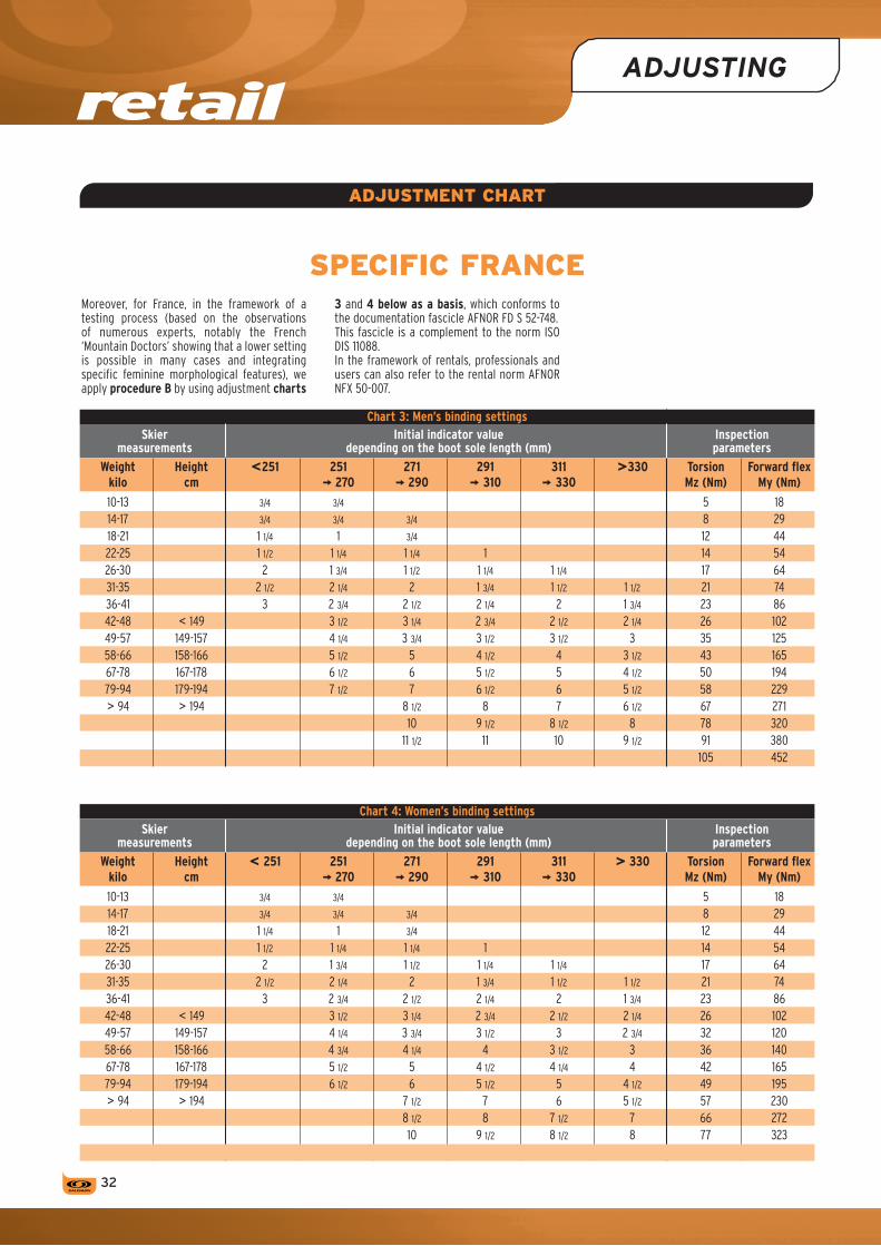
retail
�2
ADJUSTING
Moreover, for France, in the framework of a testing process (based on the observations of numerous experts, notably the French ‘Mountain Doctors’ showing that a lower setting is possible in many cases and integrating specific feminine morphological features), we apply procedure B by using adjustment charts
3 and 4 below as a basis, which conforms to the documentation fascicle AFNOR FD S 52-748. This fascicle is a complement to the norm ISO DIS 11088. In the framework of rentals, professionals and users can also refer to the rental norm AFNOR NFX 50-007.
ADJUSTMENT CHART
SPECIfIC fRANCE
Chart 3: Men’s binding settings Skier Initial indicator value Inspection measurements depending on the boot sole length (mm) parameters
Weight Height <251 251 271 291 311 >330 Torsion Forward flex kilo cm ¬ 270 ¬ 290 ¬ 310 ¬ 330 Mz (Nm) My (Nm)
10-13 3/4 3/4 5 18 14-17 3/4 3/4 3/4 8 29 18-21 1 1/4 1 3/4 12 44 22-25 1 1/2 1 1/4 1 1/4 1 14 54 26-30 2 1 3/4 1 1/2 1 1/4 1 1/4 17 64 31-35 2 1/2 2 1/4 2 1 3/4 1 1/2 1 1/2 21 74 36-41 3 2 3/4 2 1/2 2 1/4 2 1 3/4 23 86 42-48 < 149 3 1/2 3 1/4 2 3/4 2 1/2 2 1/4 26 102 49-57 149-157 4 1/4 3 3/4 3 1/2 3 1/2 3 35 125 58-66 158-166 5 1/2 5 4 1/2 4 3 1/2 43 165 67-78 167-178 6 1/2 6 5 1/2 5 4 1/2 50 194 79-94 179-194 7 1/2 7 6 1/2 6 5 1/2 58 229 > 94 > 194 8 1/2 8 7 6 1/2 67 271 10 9 1/2 8 1/2 8 78 320 11 1/2 11 10 9 1/2 91 380 105 452
Chart 4: Women’s binding settings Skier Initial indicator value Inspection measurements depending on the boot sole length (mm) parameters
Weight Height < 251 251 271 291 311 > 330 Torsion Forward flex kilo cm ¬ 270 ¬ 290 ¬ 310 ¬ 330 Mz (Nm) My (Nm)
10-13 3/4 3/4 5 18 14-17 3/4 3/4 3/4 8 29 18-21 1 1/4 1 3/4 12 44 22-25 1 1/2 1 1/4 1 1/4 1 14 54 26-30 2 1 3/4 1 1/2 1 1/4 1 1/4 17 64 31-35 2 1/2 2 1/4 2 1 3/4 1 1/2 1 1/2 21 74 36-41 3 2 3/4 2 1/2 2 1/4 2 1 3/4 23 86 42-48 < 149 3 1/2 3 1/4 2 3/4 2 1/2 2 1/4 26 102 49-57 149-157 4 1/4 3 3/4 3 1/2 3 2 3/4 32 120 58-66 158-166 4 3/4 4 1/4 4 3 1/2 3 36 140 67-78 167-178 5 1/2 5 4 1/2 4 1/4 4 42 165 79-94 179-194 6 1/2 6 5 1/2 5 4 1/2 49 195 > 94 > 194 7 1/2 7 6 5 1/2 57 230 8 1/2 8 7 1/2 7 66 272 10 9 1/2 8 1/2 8 77 323 89 384

› Sk
i - B
iNDi
NG -
SNOW
BLAD
E
��
FINAL CHECKING
After the bindings have been properly mounted and adjusted, visually inspect the ski/boot/ binding system.
› The boot:Check:- for gross irregularities where the boot contacts
the binding and the AFD (deformation, wear,...),
- that the boot conforms to the norm (DIN, ISO or ASTM markings).If the boots are not marked, check with the supplier.These bindings are not designed to function with boots that do not conform to the norm.
- that the boot has not started to crack or break.
The boot toeCheck for the absence of:- rubber and/or metal tip protectors- mold flashings- a ramp or bevel in front of the AFD area- grid pattern or tread in the AFD area- excessive wear- a toe sole extension with corner radius of less
than 7 mm- asymmetrical shape of the toe sole.The boot heelCheck for:- debris lodged in the sole- scraped or improperly canted boot sole- cut-outs in the heel sole that catch on the
entry pedal- cut-outs in the sole that impede proper brake
function.Note: If you are uncertain of boot compa-tibility, perform the ‘Clean vs Lubricated’ test. Boots that fail this test or violate any of the above points should not be used with any Salomon binding.
› The ski:Check for:- mounting screws protruding through the base- delaminated sidewall. This can be detected by
running your fingers along the sides of the ski.- base plate flush with ski surface- delaminated topskin- pre-drilled holes. Bindings should not be
installed on skis that have already been drilled for three or more sets of bindings.
› The binding:The toe pieceCheck for:- stripped, loose or missing screws- condition and location of the AFD (ripped,
loose, imbedded dirt, boot sole pattern, tread imprint, etc)
- condition of anti-friction inserts (where applicable)
- missing or unreadable adjustment indicators and missing windows
- bent or broken base plate, principal axis or housing
- stripped or jammed toe height and cup adjustment screws
- jammed release adjustment- other visible wear.
The heel pieceCheck for:- stripped, loose or missing screws- improperly installed brake- defective heel track- bent or broken base plate, track or heel guide- missing Delrin inserts in the heel guide- jammed release adjustment- unreadable indicators- other visible wear.
The ski brakeCheck for:- improper installation- broken entry pedals- bent brakearms- strength of ski brake
A brake must not compress totally when the ski is set on a flat surface.
- other visible wear- proper position of brakes
They shouldn’t touch the ski while they are functioning (especially on fat skis).
The complete systemPlace the boot in the binding and check the accuracy of:- toe height adjustment (if applicable)- toe cup width adjustment (if applicable)- forward pressure adjustment- release adjustment settings- symmetrical mounting of bindings to ski center
line (+/- 1 mm)This should be in the same location on both skis.If you discover a correctable problem, repair the problem and re-test. If the system still falls outside the “in-Use range”, perform the ‘Clean vs Lubricated’ test.
A Salomon certified technician must sign or initial the Workshop form indicating that all systems inspections have been performed.
A final check is your quality control measure to verify that all required procedures have been properly completed and involves the following steps:
1. Visual inspection of system components.2. Test for elastic travel and return.3. Release value within specified range and
boot-binding compatibility.
VISUAL AND MECHANICAL INSPECTIONS
VISuAL INSPECTION OF SySTEM COMPONENTSTROuBLESHOOTING PROCEDuRE 1
2
3

FINAL CHECKING
retail
��
TEST fOR ELASTIC TRAVEL AND RETURN
› Laterally:Secure the ski. Hit the forefoot area of the boot with a rubber hammer. Use sufficient force to move the boot off-center, but not hard enough to release the system.The boot should move off-center at least 5 mm and return to center within 2 mm of its original position.› Vertically:Put the boot in the binding, depress the heel lever while pulling forward on the upper cuff of the boot until the boot heel lifts at least 5 mm. Release both hands simultaneously. The boot should go back in place quickly and smoothly.This check can be performed either manually or by using a mechanical device. If a measuring device is used, follow the recommendations of the test device manufacturer for proper procedure.
RELEASE VALUE WITHIN SPECIfIED RANGE
AND BOOT/BINDING COMPATIBILITY
Testing of release values with a test device is recommended (fig. 1).If a test device is not used, the skier should be informed.In addition, the skier must be warned about the risk of possible breakage of boots and bindings that have been subjected to shocks or abnormal stress.› Test the toe:First, exercise the toe by releasing it once in each direction.Then, using test device, measure and record the twist release value in each direction. The measured release value should be considered to be the middle quantitative value of three measured releases.If the first two measured values are the same, there is no need to take a third measurement. See examples of middle quantitative values (Chart. 1).The toe passes this inspection if the middle quantitative values in both directions fall within the ‘Inspection range’.See sample “System inspection ranges” (Chart. 2).Symmetry test noteYou should be aware of the possibility of an asymmetric release.If your tested values for clockwise and counter-clockwise release appear to be at opposite extremes of the inspection range, you may have an installation error or incompatible boot.Troubleshoot the system and re-test after the problem has been corrected.› Test the heel:First, exercise the heel by releasing it once. Using a test device, measure and record the heel release value.
Chart. 1 Three release values Middle quantitative value 45 - 40 - 50 45 60 - 50 - 50 50 30 - 40 - 50 40 55 - 65 - 60 60
Chart. 2 - System inspection ranges
43
50
58
67
78
InspectionTolerance range
ReadjustmentTolerance range
The middle quantitative value of three heel releases should fall within the +/- 15% “inspection range”.› Release value verification - failure:When the technician is satisfied that all required procedures have been completed according to Salomon’s recommendations in this manual, he or she must sign the Workshop Form. (The signing technician must currently be certified by Salomon.)Note: During manufacturing, Salomon precision tests every binding up to 5 times to assure that it functions properly and is calibrated correctly. It is extremely rare that a new component would be out of calibration unless there is damage.› Troubleshooting:Boot/binding systems wear with time. Mechanical inspection allows you to identify when the ski/boot/binding system is not working as it was originally intended. Readjustment of the binding is not a sign of malfunction, but can be a sign of normal wear.› Test for lateral travel - failure:Re-check all binding-to-boot adjustments. Re-inspect the boot and the binding according to the Visual Inspection criteria. If the boot is dirty, clean the sole with a solution of soap and water.If the binding is dirty, clean it according to the procedures described in this chapter under ‘Maintenance’.Re-test the system for elastic travel and return.› Test for vertical elastic travel - failure:Clean the boot sole of any snow, dirt or debris. Check for excessive wear at the boot heel. Repair or replace any non-DIN boot. Check that the boot enters the binding correctly. Align the boot with toe and heel
cups and re-insert the boot. Check the release setting. It should not exceed the minimum or maximum visual indicator setting and should be set appropriately for the skier.If the measured +/- Mz and My values are located outside of the +/- 15% inspection range, consult the manufacturer’s instructionsfor procedures concerning malfunctions. If after this procedure, the measured values are within the readjustment range of +/-30%, the binding can be readjusted.These readjustments should allow you to obtain measured values as close as possible to the selected individual release torque within the +/- 15% range.If the release is still outside the +/- 30% readjustment range after having followed the procedures for malfunctions, do not readjust the binding unless it is specifically authorized by the manufacturer (chart. 1).
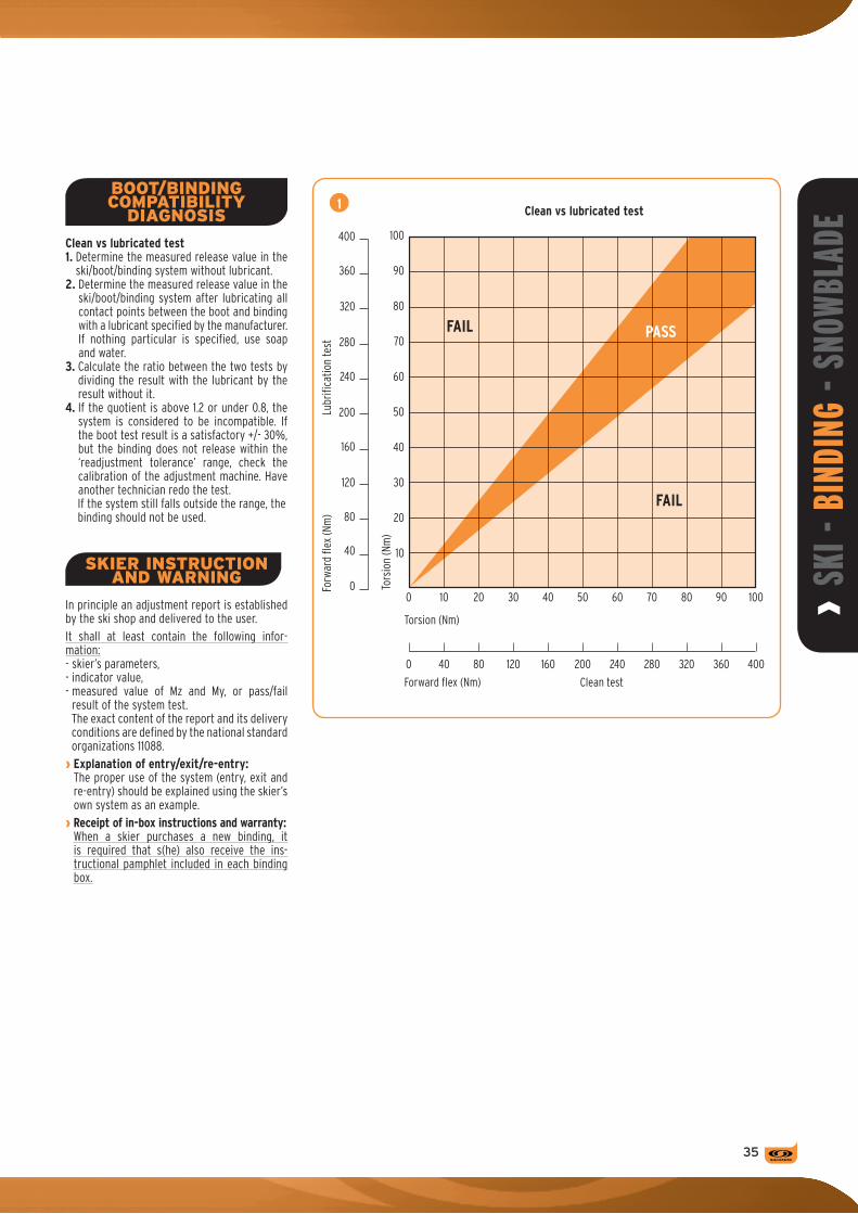
› Sk
i - B
iNDi
NG -
SNOW
BLAD
E
��
0 10
10
20
30
40
50
60
70
80
90
100
20 30 40 50 60 70 80 90 100
0 40 80 120 160 200 240 280 320 360 400
FAIL
FAIL
PASS
Torsion (Nm)
Tors
ion
(Nm
)
Forward flex (Nm) Clean test
0
40
80
120
160
200
240
280
320
360
400
Forw
ard
flex
(Nm
)Lu
brifi
catio
n te
st
1 Clean vs lubricated test
BOOT/BINDING COMPATIBILITY
DIAGNOSIS
Clean vs lubricated test1. Determine the measured release value in the
ski/boot/binding system without lubricant.2. Determine the measured release value in the
ski/boot/binding system after lubricating all contact points between the boot and binding with a lubricant specified by the manufacturer. If nothing particular is specified, use soap and water.
3. Calculate the ratio between the two tests by dividing the result with the lubricant by the result without it.
4. If the quotient is above 1.2 or under 0.8, the system is considered to be incompatible. If the boot test result is a satisfactory +/- 30%, but the binding does not release within the ‘readjustment tolerance’ range, check the calibration of the adjustment machine. Have another technician redo the test.If the system still falls outside the range, thebinding should not be used.
SkIER INSTRUCTION AND WARNING
In principle an adjustment report is established by the ski shop and delivered to the user. It shall at least contain the following infor-mation:- skier’s parameters,- indicator value,- measured value of Mz and My, or pass/fail
result of the system test.The exact content of the report and its delivery conditions are defined by the national standard organizations 11088.
› Explanation of entry/exit/re-entry:The proper use of the system (entry, exit and re-entry) should be explained using the skier’s own system as an example.
› Receipt of in-box instructions and warranty:When a skier purchases a new binding, it is required that s(he) also receive the ins-tructional pamphlet included in each binding box.

rental
��
Brak
e
REF
DIN
scal
e
Heig
ht in
mm
Skie
r w
eigh
t (k
g)
Skie
r w
eigh
t (L
bs)
SCP
(Sal
omon
Con
trol
Ped
al)
Vert
ical
pro
gres
sive
piv
ot
Ski /
bin
ding
inte
rfac
e
High
late
ral T
rans
mis
sion
Adju
stm
ent
rang
e (m
m)
Wei
ght
of 1
/2 p
air
(in
g)
Adju
stm
ent
rang
e (u
S si
zes)
Ti
Seni
or /
Jun
ior
norm
s
Auto
mat
ic w
ing
adju
stm
ent
Rem
ovab
le b
rake
Rental binding range
pre-Mounted
KR z12 Ti B80 554833 4-12 31,5 30-107 66-235 • • + • • 122 15 1031 Ti S
KR z12 Ti B90 554836 4-12 31,5 30-107 66-235 • • + • • 122 15 1032 Ti S
KR z10 B80 554839 3-10 31,5 30-107 66-235 • • + • • 122 15 1305 S
KR z10 B90 554842 3-10 31,5 30-107 66-235 • • + • • 122 15 1308 S
KR 710 B80 554845 3-10 31,5 30-107 66-235 • • • • 122 15 1400 S
JR 610 B80 B80 304344 3-10 31,5 30-107 66-235 • • • 122 15 1400 S
alacarteModelS
NR z12 Ti SC B80 788896 4-12 31,5 42-120 92-264 • • + SC • • 122 15 1233 Ti S
NR z12 Ti SC B90 788897 4-12 31,5 42-120 92-264 • • + SC • • 122 15 1234 Ti S
NR z12 Ti SC B100 788901 4-12 31,5 42-120 92-264 • • + SC • • 122 15 1236 Ti S
NR z10 Ti SC B80 788905 3-10 31,5 30-107 66-235 • • + SC • • 122 15 1220 Ti S
NR z10 Ti SC B90 788906 3-10 31,5 30-107 66-235 • • + SC • • 122 15 1221 Ti S
NR 710 SC B80 788920 3-10 31,5 30-107 66-235 • • SC • • 122 15 1362 S
NR 710 SC B90 788921 3-10 31,5 30-107 66-235 • • SC • • 122 15 1363 S
NR 609 SC B80 788923 2,5-9 31,5 30-100 66-220 • SC • • 122 15 1285 S
NR 609 SR B80 788924 2,5-9 18 30-100 66-220 • SR • • 80 10 1016 S
junior
NR 608 SC B80 788925 2-7,5 31,5 22-85 55-187 • SC • • 122 15 1285 S
NR 607 SR B80 788922 2-7 18 22-80 55-180 • SR • • 80 10 1016 S
NR Tz 5 SC JR 788872 0,5-4,5 22 10-50 22-110 + SC • • 104 13 681 J & S
NR Tz 5 SR JR 788873 0,5-4,5 14 10-50 22-110 + SR • • 56 7 572 J & S
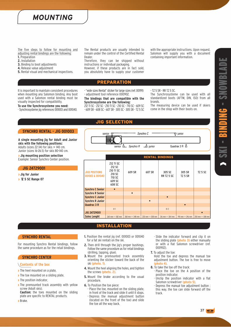
› Sk
i - B
iNDi
NG -
SNOW
BLAD
E
�7
MOUNTING
It is important to maintain consistent procedures when mounting any Salomon binding. Any boot used with a Salomon rental binding must be visually inspected for compatibility.To use the Synchrosysteme you need:- Synchrosysteme jig references 001003 and 001040.
- “wide sizes Rental” sticker for large sizes (ref. 001191)- adjustment tool reference 000902.The bindings that are compatible with the Synchrosysteme are the following:Z12 TI SC - Z12 SC - Z10 TI SC - Z10 SC - 710 SC - 609 SC - 609 SR - 608 SC - 607 SR - 305 SC - 305 SR - TZ 5 SC
JIG SELECTION
The five steps to follow for mounting and adjusting rental bindings are the following:1. Preparation2. Installation3. Binding to boot adjustments4. Release value adjustment5. Rental visual and mechanical inspections.
The Rental products are usually intended to remain under the control of the Certified Rental Dealer.Therefore, they can be shipped without instructions or individual packaging.However, if these products are in fact sold, you absolutely have to supply your customer
with the appropriate instructions. Upon request, Salomon will supply you with a document containing important information.
- TZ 5 SR - RR TZ 5 SC. The Synchrosysteme can be used with all standardized boots (AFTM, DIN, ISO) from all brands. The measuring device can be used if skiers come in the shop with their boots on.
SyNCHRO RENTAL
For mounting Synchro Rental bindings, follow the same procedure as for the retail bindings.
SyNCHRO CENTER
Contents of the box
› The heel mounted on a plate,› The toe mounted on a sliding plate,› The position indicator,› The premounted track assembly with yellow
screw (Adult skis).Caution: the toes mounted on the sliding plate are specific to RENTAL products.
› Brake.
1. Position the rental jig (ref. 001003 or 001040 for a fat ski rental) on the ski.
2. Then drill through the jig’s proper bushings. Follow the same procedure as for retail bindings (drilling, tapping, glue).
3. Mount the premounted track assembly orienting the sticker toward the back of the ski (photo. 1).
4. Mount the heel aligning the holes, and tighten the screws (photo. 2).
5. Mount the brake according to the usual procedure.
6. To Position the toe piece:- Place the toe, mounted on the sliding plate,
in front of the track and slide it until it stops.- Depress the manual adjustment button
(located on the front of the toe) and slide the toe all the way back.
PREPARATION
INSTALLATION
- Slide the indicator forward and clip it on the sliding plate (photo 3) either manually or with a flat Salomon screwdriver (ref. 000902).
7. To adjust the toe: Hold the toe and depress the manual toe adjustment button. The toe is free to move (photo 4).
8. To take the toe off the track:- Place the toe on the A position of the
position indicator.- Unclip the position indicator with a flat
Salomon screwdriver (photo 5).- Depress the manual toe adjustment button ;
this way, the toe can slide forward off the track.
JIGS POSITIONS001003 & 001040
Synchro C SeniorSynchro R SeniorSynchro C JuniorSynchro R Juniorquadrax 3 R
JIG 24729001Soles Lenght
•
@ 1
260 mm <-> 382 mm
•
268 mm <-> 348 mm
•
230 mm <-> 308 mm
•
@ 2
216 mm <-> 304 mm
•
190 mm <-> 246 mm
Z12tiscZ12sc
Z10tiscZ10sc710sc609sc608sc
609sR 607sR 305scRRtZ5sc
305sRtZ5sR
RENTAL BINDINGS
SyNCHRO RENTAL - JIG 001003
A single mounting jig for Adult and Junior skis with the following positions:Adults (sizes 22-34) for skis > 140 cm.Junior (sizes 16-26.5) for skis 80-140 cm.› Jig mounting position selectionExample: Senior Synchro Center position.
JIG 24729001› Jig for Junior› Tz 5 SC Range 07
•200 mm <-> 308 mm
tZ5sc

MOUNTING
rental
1
4
2
5
3
�8
SYNCHRO CENTER
› Binding to boot adjustments without using the Synchrosysteme:Easy glide manual heel adjustment:- Position the boot in the toe piece.- With one finger, simply lift the adjustment
loop at the back of the heel and slide it forward until the binding cup contacts the boot heel.
- Release the loop, push boot down and check the forward pressure adjustment. To do this, you should see a little metal guide in the indicator (fig. F).Note: If a correction is necessary, reopen the heel to move it and then re-check.
› Wing adjustment:Follow the procedure.
› Rental toe height adjustment:Follow the procedure.
› Release value adjustment:All Salomon rental bindings must be adjusted by using the Adjustment chart.
› Rental visual and mechanical inspection:Whenever a binding looks particularly dirtyor if visual inspection reveals that somethingmay be wrong with the system, the systemshould be cleaned, lubricated and subjectedto mechanical inspection.
F
MAINTENANCE
Proper maintenance of rental systems includes a complete inspection of the entire rental inventory prior to the ski season. This should be followed by periodic in-season inspections to help ensure that all components are functioning correctly.› Pre-season:1. Visually inspect and clean all equipment in
inventory.2. Test all bindings using selected reference
boots and a mechanical testing device.3. Test a sampling of boots in inventory using
selected reference bindings and a mechanical testing device.
› In-season:1. At specified intervals, select samples from
inventory to be tested.2. Inspect visually using the same procedures
that apply to pre-season.› End of season:To prepare the rental equipment for summer storage, lower all the binding release adjust-ments to the minimum. Close the binding heel pieces.
Visually inspect, clean, repair and lubricate each rental system:1. To remove the heel, slide the housing
backward off the track.2. Clean the track with a damp rag or cloth. Do
not use solvents, hot water or pressurized water to clean bindings. Solvents may cause permanent damage to the plastic structure by dangerously modifying the products’ technical characteristics. The markings can also be erased.
3. Wipe any dirt from the underside of the heel housing and from the area under the open heel cup.
4. Apply Salomon grease (reference 000905) sparingly to the underside of the heel housing, the heel track and the area under the open heel cup.
5. Replace the heel on the track.6. The brake is removable to facilitate ski
maintenance.7. Store in a cool, dark, ventilated place.
SYNCHRO CENTER

› Sk
i - B
iNDi
NG -
SNOW
BLAD
E
��
INSPECTION
AID FOR APPLICATION OF ISO 13993 concerning - rental ski shop practice - sampling and inspection of complete and incom-plete alpine ski-binding-boot systems in rental
following program (this comes out of the ISO 13993 standard).
applications (this supplement does not replace ISO 13993).To keep your rental equipment in good condition while minimizing liability we recommend the
S ince i t is impract ica l to perform a fu l l inspection each time a system is rented, a routine of preseason and inseason inspections has been developed to verify release indicator accuracy, confirm correct equipment function,
and assure proper assembly and adjustment procedures by the rental shop staff.Fully implemented, the procedures that follow provide rental shop customers a standard
of care equivalent to that provided retail shop customers under current ISO and ASTM standards.
RENTAL INSPECTION SUMMARY
INSEASON INSPECTION
Inseason inspections are performed on complete rental systems to ensure that the equipment is adjusted appropriately and continues to function correctly. Typically 5% of the rental inventory is tested during each two weeks sampling period. The random sample is equally divided between equipment that is available for rental and equipment that has just been rented. The equipment in the ‘as rented’ category is from real skiers in the condition in which it is either dispatched or returned, while the ‘available for rental’ equipment may be set up for fictitious skiers. Only single skis, not pairs, are tested, and testing at the toe is only required in one direction. A count is maintained of test results which exceed allowable limits. The magnitude and frequency of these deviations determines the frequency of future inspections. Shops which fail an inspection must sample daily until the source of the problem is found and corrected. Then, as inspection results improve, the frequency of sampling and inspection is relaxed.
PRESEASON INSPECTION
Preseason inspections are performed on components of the release system: bindings and boots. All rental bindings, new and used, are visually inspected, and then tested using specially selected Reference Boots. Bindings that fail go through a troubleshooting procedure to identify and correct the deviation or malfunction.If this procedure does not correct the problem, the binding is removed from inventory. All rental boots, new and used, are visually inspected for damage, wear, contamination, broken or missing parts, or inferior materials at contact points with the binding. In addition, one boot per ‘cell’ is tested for boots that are new to the rental inventory. A cell is all boots of the same make, model, age, and shell size. A random selection of 5% of all boots, previously accepted into inventory, is also tested. Tests are performed with a test device and a pair of specially selected reference bindings. If a boot fails, all boots from that cell are then tested. Boots that fail and cannot be repaired are removed from inventory.

INSPECTION
rental
IMPORTANT TERMS
Correction FactorThe value that must be added or subtracted from the initial visual indicator setting to bring the test result within the Inspection Tolerance (or Inspection Range).
Directions of ReleaseUnless otherwise specified (see Inseason Inspection), the directions of release to be tested are forward lean and clockwise and counterclockwise in twist.
Test DeviceA device which meets ISO standard 11110 (or ASTM standard F1061) and has been checked and maintained in the manner specified by the device manufacturer.
Test Result or Release TorqueThe middle quantitative value of three tests made in the same direction. (Add other terms from ISO 13993 or ASTM F1064 that are not defined elsewhere in the tech manual).
PRESEASON TEST
Reference Boot Selection
The Reference Boot is a boot of a designated sole length which is otherwise typical of the boot inventory. Use the procedure below if the boot inventory includes several models and a representative boot can not be easily identified.
1. Select five single boots with sole lengths as specified in Chart A for the binding type to be tested: adult, junior, or child.
2. Clean all five boots with a mild detergent and water.
3. Adjust a rental binding to the release indicator setting specified in Chart A for the binding type.
4. Fit the binding to the boots and determine the Release Torque in all three directions of release (forward lean and both directions in twist- three releases in each direction).
5. Average the Release Torque for CW and CCW twist release.
6. Reject and replace any boot with a CW to CCW difference of more than 6 Nm for adult boots or 4 Nm when testing child boot types.
7. Rank the five twist results and select as the Reference Boot for twist, the middle boot.
8. Rank the five forward lean results and select as the Reference Boot for forward lean, the middle boot.
Preseason Binding Inspection
The procedure that follows is an integral part of preseason maintenance. It is also a good way to determine if mainte-nance is adequate and which units have outlived their usefulness and must be removed from inventory.
1. Clean areas of the bindings that contact the boot and perform all preseason binding maintenance.
2. Visually or manually check:a. AFD condition.b. Brakes function.c. Release indicator readability and travel.d. Screw tightness.e. (other product specific inspections if required)
3. Fit each binding to the Reference Boot and adjust the release indicators to the value in Chart A.
4. Check that the heel track and toe track code (if any) agree with the sole length code (if any) of the Reference Boot.
5. With the Reference Boot in the binding, verify elastic travel of the toe piece by striking the boot toe with a mallet or dead hammer and checking that the toe piece returns the boot quickly and completely to center.
6. Verify elastic travel of the heel piece by lifting the boot while depressing the heel piece cocking lever and checking that the heel piece returns the boot quickly and completely to the latched position. (other product specific procedures if required).
7. Manually release the binding 3 times in each direction.
8. Lubricate all boot/binding interfaces with a mild liquid detergent and water solution.
9. With the Ski Binding Test Device determine the Release Torque for each direction of release (forward lean and both directions in twist).
10. Record “PASS” in the binding's maintenance record if Test Results are within the Inspection Ranges provided in Chart A.
11. Set the ski aside if the Test Result in any directions of release is outside the Inspection Range in Chart A.
12. Follow Troubleshooting Procedure for units which have been set aside and retest if changes in the unit's condition or adjustment are made.
13. Record “FAIL” in the binding's maintenance record if, after troubleshooting, test results in any direction of release are outside the In-Use Range. Replace the ‘failed’ unit and retest before returning the ski to service.
14. If after troubleshooting, Test Results are outside the Inspection Range but within the In-Use Range, apply a Correction Factor to the unit and note the Correction Factor for that unit in the binding's maintenance record.
15. If many bindings fail, check the test device and re-inspect the Reference Boot. If necessary, select another boot and retest the bindings.
INSPECTION PROCEDURES
Chart A: Preseason Binding Inspection
Skier Binding Sole Release Reference Reference Twist Forward Twist Forward code type length indicator torque torque inspection inspection in-use in-use mm setting twist forward range range range range Nm Nm Nm Nm Nm Nm
E Children 258 2,0 20 75 17-23 64-87 14-27 52-102
J Junior 306 4.3 43 165 37-50 141-194 31-58 120-229
L Adult 327 5.8 58 229 50-67 194-271 43-78 165-320
�0

› Sk
i - B
iNDi
NG -
SNOW
BLAD
E
�1
Preseason Boot Preparation
The procedure that follows is an integral part of preseason maintenance.
1. Clean all boots with (a mild detergent and water), and repair or replace damaged or missing parts.
2. Visually check:a. Conformance with ISO and other applicable
standards. If the boot contacts the binding, brake, or AFD in areas other than the designated contact points, it may be incompatible with the binding (product specific figure or description).
b. Boot material. If the sole at the contact points with the binding or AFD can be scratched with a finger nail, the boot may be of inferiors quality and incompatible with the binding.
c. Boot sole condition. If the boot sole is damaged, worn, or contaminated at contact points with the binding or AFD in a manner which can not be corrected, the boot may be incompatible with the binding.
d. Brake compatibility with sole. e. Rubber and/or metal sole protectors.
If such materials contact the binding or AFD the boot may be incompatible with the binding.
f. Mold flashings. Flashing which can be seen or felt at contact points with the binding, brake, or AFD must be carefully removed.
3. Remove from inventory all boots that have failed the visual check.
Preseason Boot Sampling
Although sampling eliminates the need to test every boot before the season starts, the sample chosen must be representative of the inventory.
1. For boots that are new to inventory or have never been inspected, take a single boot from each cell (a cell is all boots of the same make, model, year, and shell size).
2. For used boots, take a 5% (but not less than 16 or more than 80) random sample of the entire inventory. Make sure that there is at least one boot from each cell in the sample.
Preseason Boot Inspection
The procedure that follows helps to assure both boot/binding compatibility and boot interchange ability.
Note: when using Chart A, in the Boot Inspection procedured that follow, the Sole Length and Release Indicator Setting Columns should be ignored.
1. Randomly select a pair of bindings that have passed the preseason inspection from each binding type; adult, junior, child.
2. Lubricate all boot/binding contact points with a mild liquid detergent.
3. Without regard to whether the boot is new or used, sort the sample by sole type and length according to the 20 mm Sole Length Categories defined by binding adjustment chart (ISO 11088) .
4. In each Sole Length Category rank the boots by sole length and select the middle boot.
5. In each Sole Length Category fit the appropriate reference bindings to this “typical” boot and adjust the two bindings to release as close as practical to the Reference Torque in Chart A. Use the Reference Torque corresponding to Skier Code (L) for the Adult binding, (J) for the Junior binding, and (E) for the Child binding.
6. Rinse the lubricant from one binding and mark it “clean”. Mark the other “lubricated”.
7. Test each boot in the Sole Length Category with the clean Reference Binding and then the lubricated Reference Binding in both twist and forward lean (only one direction in twist is required for the clean binding).
8. Set aside any boots for which the lubricated Test Result is more than 20% less than the clean Test Result in the same direction of release or the lubricated Test Result in any direction of release is outside of the Inspection Range provided in Chart A for the Skier Code used to set up the Reference Binding (L, J, or E).
9. Repeat the Visual Check on all boots that have been set aside, correct any defects noted, and retest. Remove from inventory boots that fail the retest.
10. Check all other boots from the same cell (make, model, year, and shell size) as those that failed.
Note: On completion of the preseason inspection, clean the liquid detergent from the equipment (and lubricate the binding before returning it to service).

rentalINSPECTION
Sample Frequency
Random sampling is conducted throughout the entire season. Frequency is as follows:
1. After 7 days of operation.2. If the sample passes the next sampling is
taken after another 7 days of operation.3. If two consecutive samples pass, sampling
frequency is increased to 14 days.4. If a sample fails at any time, daily sampling
is instituted until two consecutive samples pass, at which point weekly sampling resumes.
Sample size
Sample size is 5% of inventory but not less than 16 nor more than 80 units as noted in Chart B. Sample size is based on average daily output. If rental output drops below 50% of capacity over the sampling period, the sample size can be reduced proportionately.
Inseason Inspection
1. Take a random sample of the rental inventory as determined by Chart B. Take half the sample from inventory as it is either rented or returned and the remainder from inventory available for rental .
2. Wipe the boot clean and cycle the boot/ binding systems at least once in each direction.
3. Test sample units in Twist (one direction only) and Forward Lean.
4. Compare the Test Results with the Inspection Range for the appropriate Skier Code.
The Inseason Inspection is a test of complete systems and all the procedures used by the rental staff to assemble and adjust the system.
The program uses random samples of rental inventory taken at routine intervals. Any sampling program that gives every unit of
inventory the same chance as every other of being picked is valid.
5. If the results are within the Inspection Range, the unit passes.
6. If the results are outside Inspection Range but within the In-Use Range, count the unit as a Class I Deviation.
7. If the results are outside the In-Use Range, count the unit as a Class II Deviation.
8. Check elastic travel and visually inspect the ski brake function, interface areas between boot and binding, including AFD, lug height adjustment (if appropriate), and forward pressure. Count any deficiencies as Class I Deviations.
9. If more than the maximum number of Class I Deviations given in Chart B are found in the sample, or a single Class II Deviation is detected the sample fails and daily sampling must be conducted until the problem which led to the failed sample is found and corrected. For Troubleshooting Procedures following a Failed Inseason Inspection.
10. Record the date the sample was tested, the number of units tested the number of Class I and Class II (or III) Deviations, whether the sample passed or failed and any actions taken. There is no need to record the identity of units tested or actual Test Results.
Chart B: Sample Size
Inventory Size 100 200 300 400 500 600 700 800 900
Sample Size Units 16 20 30 40 50 60 70 80 80
Maximum Class I Dev. 3 4 6 8 10 12 14 16 16
INSEASON SAMPLING AND INSPECTION
�2

p
› Sk
i - B
iNDi
NG -
SNOW
BLAD
E
��
maintenancerepairs
2
SKI CHECK-uP- Visually check to determine what needs to be
tuned.- Remove major deep scratches on edges with
whetstone.- Remove any traces of wax or grease.
FILL IN ANy HOLES IN THE BASEDepending on the conditions of the base and materials available:a) Grind entire base surface (photo 1).b) Fill-in scratches with base repair material.c) Repair any large damaged areas with base
patch/die.
STONE GRINDINGFor Prolink skis, install the Binding-Bridge kit according to the ‘Maintenance specifics’ paragraph.
a) Surface smoothing– Place the skis on a flat surface.– Eliminate any excess polyethylene on the base
with a hand base plane to decrease the risks of contaminating the stone.b) Semi Finishing
– Stone grind until the base becomes flat and glossy.
– Avoid overheating and use of a dirty stone (lengthwise streaks on base are from stone contaminant).
- Dress the stone regularly to keep it in good condition (when using a belt grinding machine: use 80 grit belt).c) Finishing (photo 2)
- Stone grind to obtain a fine structure (when using a belt grinding machine: use 150 grit belt).
- Do not use a dirty stone which creates fluff/hair.d) Beveled/recessed finish
For skis with beveled/recessed finish, we recommend a straight, fine stone-ground structured base.
Note: always make the last run in this direction: Tip–Tail. Concerning the machine parameters, consult the machine manufacturer.
STONE GRINDING THE SKI BASE
Values from Wintersteiger machines (Micro 81 – Micro 91) or equivalent machines.
Surface Smoothing Semi Finishing Finishing
Grinding Grinding Grinding
Rotation speed Rotation speed Rotation speed 1000 t/mn 800 to 900 t/mn 400 to 500 t/mn
Pressure 2,5 Pressure 2,5 Minimum Pressure Ski feed speed Ski feed speed Ski feed speed 10 m/mn 10 m/mn 10 - 11 m/mn
Dressing Dressing Dressing Dressing rate Dressing rate Dressing rate 9 - 12 mm/s 4 - 16 mm/s 7 - 8 mm/s (dependingontheconditionoftheski)
Dressing speed Dressing speed Dressing speed Micro automatic (1300 t/mn) (1300 t/mn) (1300t/mn)
1
The ski tune-up involves three steps:1. Daily check-up
- at the end of everyday of skiing.2. Machine tuning
- for quick work.3. Complete hand tuning
- for skier’s specific needs.
Good ski maintenance is just as important for the recreational skier as for the racer. A fine-tuned ski lasts longer. A well-prepared ski turns better, grips the snow better and glides better on all types of snow.
CHECk‑UP
- Visually check to see if any rust has developed on the edges.
- Remove any traces with fine, 220-230 grit sandpaper.
- If necessary, sharpen and polish edges using sandpaper wrapped around a file.
- Clean the base and wax with Swix wax.
SkI MAINTENANCE
MACHINE TUNING

pmaintenancerepairs
A
B1 B4
B2 B5
B3
SKI TuNING ON BEVELED/RECESSED EDGES
Parameter of the machine Beveled edge Recessed edge
Program 1 Angle 1° Angle 1°
Program from Wintersteiger machine (Trim Disc).
EDGE FINISHINGWe recommend grinding the edges with a cup grinding wheel see fig. A.- Check the angle adjustment beforehand.- Make sure the stones are well lubricated.- Make sure the edges are not burnt (brown
color).- Check the tuning lengths.- Smooth the edges by hand with a soft stone
(photo B4) or Scotch Brite® (photo B5).- Make sure all burrs are removed and smooth
down again, if necessary.
For non equiped retailers they can do a classic tuning.Lateral finish (photo B1):- Lateral finishing with lubricated 220 belt (or
use the smallest grit possible).- Pass over the edges 1-2 times depending on the
condition of the edges.- A double sided sharpener will maintain the
ski’s proper side cut.- For a performance preparation, polish the base
edge with a polishing stone or whetstone to eliminate any file marks on the edges.
- Remove burrs and polish edges with a lubricated Scotch Brite® belt machine at a slow speed (photo B3).
- Be careful to lubricate sufficiently to avoid burning the base.
- Carefully remove all burrs with a soft stone.- Quickly wipe the ski to avoid staining from the
dried lubricant.
A well-sharpened ski is always sharper underfoot than at the extremities of the ski.
��

› Sk
i - B
iNDi
NG -
SNOW
BLAD
E
��
C1
Tools:- Square- 20 cm (8 inch) file- Whetstone- Soft stone- Scrapers- Brushes- Scotchbrite®
- Sandpaper (220-320 grit)- Central holding vise- Swix waxA true bar is the basic tool for checking and assessing:- ski base flatness,- that the edge is slightly recessed from the base,- the extent of base scratches and appropriate
repair. The edge angle checking tool is used to verify that the edge has an angle of 90°.
SKI CHECK-uP- Check the base and edges of your skis with
a true bar.- If repairs are necessary, see instructions below.
SMOOTHING THE BASE AND EDGES
Classic finish: If damage is only minor, use a file to tune ; otherwise the ski must be tuned on a machine.Beveled/Recessed finish: the recommended bevel is between 1° and 1.5°.
EDGE SHARPENING - Sharpen base edges.- Sharpen side edges.On classic finish: make sure the edges are at 90°.On Beveled/Recessed finish: make sure that the beveled and recessed edge angle is between 1° and 1.5°.- Round off the tip and tail slightly.- Remove any burrs with soft stone or
Scotchbrite®.
POLISHING THE EDGESPolish the edges with a whetstone, starting first on the base and then the sides.
DE-TuNING THE EDGE ANGLE AT THE EXTREMITIES
WAXING, SCRAPING AND BRuSHINGFollow the same instructions as in machine tuning.Important: After all finishing operations (by hand or machine) it is essential to remove any burrs from edges and to polish the edges to ensure good ski performance.
Tools:- Wax remover- Iron with thermostat- Wax applicator- Plastic scraper- Brush
a) Waxing (photo C1)
- It’s best to use melted wax.- Clean the base thoroughly.- Make sure the iron is set at the appropriate
temperature so that only the wax is melted. (Temperature 110 °C +/- 5 oC or 230 °F +/- 10 °F).Excess heat (above 120 °C or 248 °F) can be harmful to both wax and ski, and can even cause permanent loss of glide qualities in the base.
- Choose a wax according to the wax manu-facturer’s recommendations.
- Melt the selected wax over the entire length of the base, and let the wax cool to room temperature.
b) Scraping (photo C2)
- Remove the excess wax with a plastic scraper from tip to tail to leave only a very thin layer.
- Remove wax from the base groove and ski edges as well.
c) Brushing (photo C3)
- Brush the base with a nylon brush (or other type depending on the structure desired) working from tip to tail.
- A rotating brush removes the structure of the base for good glide. Strap the skis together. Position the straps at the base contact points.Note: The skis can be stored ready-waxed (unscraped) for an extended period of time (e.g. between ski seasons).
C2
C3
WAXING, SCRAPING AND BRuSHING
HAND TUNING CLEANING THE SkIS
Pressurized cleaners are prohibited, as well as the following solvents:› Acetone› 95° alcohol(due to risk of damaging the cosmetics of the top surface of the ski).
MAINTENANCE SPECIfICS
Tuning skis with prolink on automatically programmable machines and machines with a lead:To be able to tune skis with the Y and V prolink, we have developed a specific tuning kit in cooperation with the Wintersteiger company.This new Prolink adapter can be mounted on the adjustable Wintersteiger bridge (ref. 2000: 7217-0111-V01) and is available at Wintersteiger under the reference 7217-0111- V05.

pmaintenancerepairs
��
REPAIRING THE SURfACE Of THE SkI
AND SNOWBLADEThere are two methods for repairing the ski surface:1) “One colored” paste + Araldite®
2) “Multi colored” Araldite® + white + coloringMaterials needed:- Araldite® 2011,- Araldite® gun 50 ml,- Araldite® coloring paste for smooth color
(DW 0131 White, DW 0133 Red, DW 0137 Black, DW 0132 Yellow, DW 0134 Green, DW 0135 Blue),
- White paste for undercoating for decoration (DW 0131 White),
- Felt pen to color the design, type 3 points, per-manent (Ref: Pantone 87828 - color number).
Accessories:- Cutter,- Adhesive tape,- Towel,- Sand paper, Grain 600.Repair process:1. With a cutter, outline the area to be repaired,
then cut the top surface (photo B1).2. Result after cutting the top surface (photo B2).3. With a cutter, score area to repair (fibers) to
improve bonding (photos B3).4. To protect top surface, put adhesive tape
around the area to repair (photo B4).5. Prepare Araldite® resin with gun.6. Which type of repair to choose:
a) One-color surface repair b) Multicolored surface repair
7. Add a small quantity of coloring paste to the Araldite® resin. Gently mix (in order to avoid bubbles) to obtain a homogeneous mixture. Add a small quantity of coloring paste (White DW 0131) to the Araldite® resin. White paste is used as a primer in order to have the desired colors afterwards. Gently mix (in order to avoid bubbles) to obtain a homogeneous mixture (photo B5).
8. Apply thicker than top surface of the ski in the areas to be filled. Wait a few moments to eliminate bubbles if necessary (photo B6).
9. Put adhesive tape on the area to avoid running. Let it dry for 12 hours (photo B7).
10. After 12 hours of drying, remove the adhesive tape from the mixture. Do not remove the adhesive tape around the area which protects the top surface from scratches. Use the flat side of a cutter to scrape off the excess mixture (photo B8).
11. Smooth it down with 600 grain sand paper. Remove the adhesive tape (photo B9).
12. Finish sanding gently in order to obtain a smooth surface. Be careful of the ski’s decor/cosmetics.
B4
B5
B6
B7
B8
B9
B1
B2
B3

› Sk
i - B
iNDi
NG -
SNOW
BLAD
E
�7
B10
B11
B12
HOW TO CREATE A DECORATION
13. For the coloring stage, do not try creating tone on tone to create the exact color of the ski. Trying to reproduce a motif of the ski design already present elsewhere is better and easier. The final layer of Araldite® tends to lighten colors (photo B10).
14. Use the Araldite® gun for a varnish finish which will protect the ski surface from cuts from the edges. A small quantity of Araldite® is sufficient.
15. Apply a fine layer of Araldite® with a cutter to avoid excessive thickness (photo B11).
16. Using a dust-free cloth, wipe off the excess Araldite® to obtain a smooth, even surface. Let it dry for 30 minutes. The repair is finished (photo B12).
THE TPP TOP SURfACE
All the adult and Rental models are protected by the TPP (Transparent Polyamide Protection). Regarding the Junior models, they are protected by TP (Transparent Protection). The transparent tops cover the cosmetics underneath, which guarantees the durability of the cosmetics.
BASE REPAIRS
› Superficial scratches:Machine tuning will make the scratch disappear (see the ski maintenance repair).› Not very deep scratches or marks to be
filled by machine:- Pour the polyethylene.- Wait 10 minutes for the material to harden.- Remove the excess polyethylene with a steel
spatula for a flat surface.- Proceed with machine tuning.› Deep cuts:- Cut out the damaged area with the base patch
die.- Cut a piece of the base material with the base
patch die.- Glue it into the damaged area.- Hold it in place with a clamp and press repair
(glue the pieces with Loctite® 406 or slow Araldite®).
- Proceed with machine tuning.
D
C
D1
yES NO
D2
D3
D4
F
E
REPLACING THE TIP PROTECTOR
NEW RENTAL TIP PROTECTOR RANGE 06”Triangle” tip protector (fig. C) compatible with following skis: Crossmax V12, Crossmax V800, Equipe SC Race, Equipe GC Race, Streetracer 800.
“Hexagonal” tip protector (fig. D) compatible with following skis: X-Wing Blast, X-Wing 10.
1. Check that the tip protector is on the right position (Salomon logo on top foil side (fig. D1).2. Set ut the tip protector on the lateral groove with a rubber hammer (fig. D2).3. Set up the tip protector on the central groove (fig. D3).4. Finish the mounting on the second lateral groove with a rubber hammer (fig. D4).
OTHERS RENTALS MODELS uSE RENTAL TIP PROTECTOR RANGE 05
”Triangle” tip protector (fig. E) compatible with following skis: Streetracer 600, Rush 800, Rush 600.
“Hexagonal” tip protector (fig. F) compatible with following skis: X-Wing 700, X-Wing 400, Siam 400, Axess 120.
1. Insert the tip protector on the ski.2. Place the 2 screws in the 2 holes face the running base and screw on (1N.m).
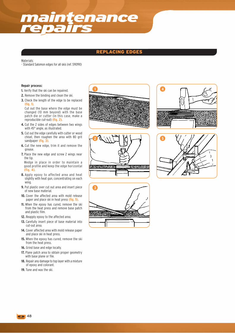
p
�8
REPLACING EDGES
Materials:- Standard Salomon edges for all skis (ref. S90190)
Repair process:1. Verify that the ski can be repaired.2. Remove the binding and clean the ski.3. Check the length of the edge to be replaced
(fig. 1). Cut out the base where the edge must be changed (10 mm beyond) with the base patch die or cutter (in this case, make a reproducible cut-out) (fig. 2).
4. Cut the 2 sides of edges between two wings with 45° angle, as illustrated.
5. Cut out the edge carefully with cutter or wood chisel, then roughen the area with 80 grit sandpaper (fig. 3).
6. Cut the new edge, trim it and remove the grease.
7. Place the new edge and screw 2 wings near the tip. Wedge in place in order to maintain a good profile and keep the edge horizontal (fig. 4).
8. Apply epoxy to affected area and heat slightly with heat gun, concentrating on each wing.
9. Put plastic over cut out area and insert piece of new base material.
10. Cover the affected area with mold release paper and place ski in heat press (fig. 5).
11. When the epoxy has cured, remove the ski from the heat press and remove base patch and plastic film.
12. Reapply epoxy to the affected area.13. Carefully insert piece of base material into
cut-out area.14. Cover affected area with mold release paper
and place ski in heat press.15. When the epoxy has cured, remove the ski
from the heat press.16. Grind base and edge locally.17. Plane patch area to obtain proper geometry
with base plane or file.18. Repair any damage to top layer with a mixture
of epoxy and colorant.19. Tune and wax the ski.
1
2
3
4
5
maintenancerepairs

› Sk
i - B
iNDi
NG -
SNOW
BLAD
E
��
BROkEN MOUNTING SCREW
MOBIL PLATE REPLACEMENT (SCP: Salomon Control Pedal)
STRIPPED SCREWS
Salomon screw extractor kit: it comes with two bits of different lengths. The longer bit is for use with the Salomon jigs for adult skis. The shorter bit should be used with the Salomon jigs for junior skis. The procedures for using both bits are the same.When a screw or tap breaks in a ski, it must be removed carefully to avoid further damage.
On Toes tighten on Interfaces and Skis (SMARTRAK GRIP/GRIP PLuS - SC - ITF): › 78830001 for 914 FIS 20 - 914 › 78830101 for z12 TI - z12 - z12 TI SC - z10
TI AXE+ - z10 TI - z10 FIS 20 - z10 TI SC - z10 - 710 TI - 710 SC - 710 - 710 ITF.
1. Dismount the Toe piece from the Ski or The Interface by completely loosening the mounting screws.
2. Dismount manually the SCP on the Toe piece.3. Take the new SCP and mount it manually
under the Toe piece.4. Tighten the Toe piece on the ski or the
Interface (4Nm Torque).
On Toes SMARTRAK PROLINK /CONTROL/ RESPONSE: › 78829401 for SMARTRAK PROLINK +914› 78829501 for SMARTRAK PROLINK &
SMARTRAK CONTROL+ z12 - z10 - 711› 78829601 for SMARTRAK PROLINK &
SMARTRAK CONTROL+ z12 TI - z10 TI - 710 TI.
Follow this procedure:1. Fit the extractor drill bit into the electric drill
with the shoulder touching the chuck.2. Fasten the appropriate jig onto the ski.3. Position the correct jig bushing directly over
the broken screw.4. Drill slowly around the broken screw using
an up-and-down movement to let the shavings escape. Caution: do not hit the screw.
5. Continue until the chuck touches the bushing of the jig.
6. The broken screw will come out inside the extractor bit.
7. Remove the screw using a pair of pliers.8. Turn the ski over and tap lightly to remove
all shavings.9. Put a drop of glue into the hole.10. Insert a plug from the kit using a hammer.11. Insert binding screw and tighten using a
hand driver. Do not over tighten.12. When a hole simply needs to be widened
to accept the plastic plugs, use an 8 mm diameter bit. Do not drill deeper than 10 mm.
For a stripped screw, use the repair kit 000878.For this operation, use the corresponding jig and position it properly by lining it up with the hole to be repaired.
When drilling, the drill bit must be perpendicular to the surface of the ski.
Make sure you don’t go beyond the plug once it is in place. You can file it down to make it level with the surface.
JUNIOR TZ 5 SC RANGE 07 . Anti friction plate replacement
1. Insert a screwdriver width 6-8 mm at the front of the plate (fig. 1).
2. Move over the screwdriver to eject the plate (fig. 2).
3. Place the new plate and hand clip it (fig. 3 & 4).
1. Put the Toe Piece out the Interface. 2. Dismount the Toe piece from the Set by
completely loosening the mounting screws.3. Dismount manually the SCP+Stirrup on the
Toe piece.4. Take the new Set SCP+Stirrup and mount it
manually under the Toe piece.5. Tighten the Toe piece on the Stirrup (4Nm
Torque).6. Remount the Toe piece on the Interface.
All Salomon bindings have replaceable SCPs.The specific SCP item numbers can be found in the Salomon Spare Parts catalog.ReplacementproceduresforscPsarefollows.
1
3
2
4

�0
notes

MODELS MONDOPOINT SIzES
15 16 17 18 19 20 21 22 23 24 25 26 27 28 29 30 31 32 22.5 23.5 24.5 25.5 26.5 27.5 28.5 29.5 30.5 31.5 33.5
ELIOS/CHARM 265 275 286 295 307 317 328 338 348
FALCON/GuN/SCARLET 265 274 285 295 305 315 326 336FLyER/KITTEN
FALCON 60 240 247 257 267 277 287 295 307
IMPACT/IDOL/FOIL/MyNX 267 277 287 297 307 317 327 337 347 357
MISSION/DIVINE 268 278 288 298 307 317 328 339 350 360
PERFORMA/IRONy 267 277 287 298 307 319 329 339 349 359 380
PERFORMA T3 266 276 285 296 306
PERFORMA T2 240 240 247 259
PERFORMA T1 203 203 223 223
SPK 287 297 307 317 327 337
SyMBIO RENTAL 263 275 284 296 306 317 326 336 345
�1
normsDInISo5355
The Alpine boot soles are standardized and bindings are designed accordingly.The standard norm concerns not only the shape and dimensions as illustrated, but also the friction coefficient of the area of the sole which is in contact with the anti-friction plate on the binding.In practical terms:The boot manufacturers who display one of the following markings: DIN, ISO, ÖN, UNI guarantee that they use standard norms.In the absence of any of these, check first with the boot manufacturer. These boots are designed for use with a pair of classic skis, and not with a monoski, snowboard or skiboard.It is the skier’s own responsibility if (s)he chooses to take the additional risks.When a pair of used boots is brought in, make sure that any worn parts are still within the norm.
Toe of the boot
Boot heel
Adult 70 min, Junior 65 min
BOOT STANDARD ISO 5355
Adult Junior
a 69 +/- 2 62 +/- 4
b 70 65
c 70 50
d 100 <--L = 300 mm* 80 <--L = 240 mm* 120 ›= --L = 300 mm* 90 ›= --L = 240 mm*
e 5 +/- 1 3 +/- 1
f 19 +/- 1 16,5 +/- 1,5
g 30 +/- 2 25 +/- 2
h 30 +/- 1 27,5 +/- 2
i 4 +/- 1 3 +/- 1
RA 41,5 +/- 3,5 35 +/- 3
RB 18 +/- 1,5 16 +/- 2
RC 37 +/- 4 27 +/- 3
RD 36,25 +/- 0,75 34,5 +/- 1
*L = boot sole length
BOOT SOLE LENGTHS
› BO
Ot
1

�2
measurer
THE SALOMON MEASURER
WARNINGSalomon developed a foot measurer that will help you provide better customer service by being able to recommend the size that corresponds to the dimensions (length and width) of the skier’s feet. However, using the measurer can never replace trying on a boot.
The volume fit can be measured in two dimensions. The morphology of the foot and physical sensitivity of each individual, according to his/her sports activities and level (comfort/performance ratio), are also determining factors in the choice of size.The Salomon measurer can be used for all Salomon footwear products (Alpine, X-C, Hiking, In-line skates, Snowboard) and takes into account the two fundamental dimensions of both feet.
› The length (main measurement): it can be read directly on 5 international size scales (US men’s/ US women’s/ UK / EUR / Mondopoint).
› The width in direct correlation with the length measured. The width measurement is particularly useful to refine the measurement in Mondopoint because it orients the customer towards the .0 sizes (narrow feet) or .5 sizes (wide feet).
PROCEDuRE
1. Have your customer take off his/her shoes and make sure that he/she is wearing appropriate ski socks (size and thickness).
2. With your customer standing up, legs parallel and knees slightly bent, make sure his/her heels and medial side of both feet are touching the sides of the measurer.
3. Slowly move the length guide (A) until it touches the tip of one foot.IMPORTANT: When you are moving the black transversal length guide, make sure you don’t put any pressure on the toes when measuring the foot. All you need to do is to barely touch the end of the longest toe. Too much pressure on the toes could lead to errors in reading by a few millimeters.
4. Read the size written vertically where the red line is in the window (B).
For Mondopoint, you have to take the width into account in the following manner: if the length of the foot measured is situated in this zone, this means the foot measures between 260 mm and 269 mm. Then, to choose between 26.0 and 26.5, you must look at the width scale (C) (in this case, make it correspond to the maximum foot width with size 26).
A foot that measures 261 mm would fit in size 26.5 (wide foot), whereas a foot that measures 268 mm can fit in size 26.0 (narrow foot) (D).
NOTE: The increases in Mondopoint sizes represented by two triangles in a rectangle is made to remind you that the boot sole lengths change at the whole sizes, not the half sizes.Remember that the size indicated on the measurer should be used to help the dealer orient the customer towards the proper size.The final choice as to the appropriate size should be left to the customer depending on whether he/she prefers a snug fit or not.In principle, a technical skier who appreciates a snug fit will choose the size indicated on the measurer, while a ‘recreational’ skier will prefer a roomier fit and will choose one size higher.
MAINTENANCE RECOMMENDATIONS
Use a damp cloth to clean the measurer. It is prohibited to use chemical agents, hot water, pressurized water, gasoline, alcohol, detergents, solvents or aerosols, which could permanently damage the plastic materials and erase the marks.
C
A
D
B

gyTECHNICAL FEATURES
Every foot deserves to be warm and comfortable.
TECHNICAL DESCRIPTIONThree-layer construction (fig.1):
A. External layer for contact with the shellFor pressure distribution and thermal insulation- Polyethylene, closed cell foam › insulation, warmth, lightness, better fit
- PVC (Thermic + Rental) › protection, ruggedness, durability
– Sensifit cuff construction for envelopment of the leg
- Supple exterior for contact with the shell and foot envelopment
- Anatomical tongue
B. Middle layerFor foot envelopment and power transmission- Thermoformable PE (CustomFit)
or self-molding PU (Autofit) or pre-formed PE (Thermic Fit) › suppleness
Transmission foam coming from the Neoprene family for quick reactions.
C. Internal layer for foot holdFor warmth and comfort- Polyurethane (PU), open cell foam › envelopment, breathability, comfort
High density CustomFit foam for superior envelopment.
The materials selected for this unique layering system were chosen to correspond to the demands of the different skier ability levels.
Salomon offer different liner models:New CustomFit generation› My CustomFit World Cup:
Best performance- Extra low volume Compact Race liner (3 layers).- Specific World Cup tongue allowing shock
absorbing.› My CustomFit Race:
Best performance- Low volume Compact Race liner (3 layers).- Rigid sole.
› My CustomFit Performance:Better comfort on the heel, metas & sole without altering performance- Two layers liner: thermoformable foam 80%
on all sensitive areas (heel + metas + sole).› My CustomFit Sport:
Better customization of the tibia and ankles- One layer liner: thermoformable foam 70%
on original areas.› My CustomFit Comfort:
Better tibial customization- One layer liner: thermoformable foam 60%
on basic area (tongue).
C B A
7
51
3
2
6
1
4
Old CustomFit generation:› Course CF Pro / CustomFit Pro:
CustomFit technology + bi-material technology.100 % foot hold and contact with the shellDue to a specific 3 layer performance construction.
› 3D CustomFit / CustomFit:Comfort, warmth and ‘customized’ envelopmentThermoformable foams allow the liner to take on the shape of the foot after a heating procedure is performed with a special machine designed by Salomon.+ Thermoformable insole (3D CustomFit)
› AutoCF:- Automoulding foam in the foot envelopment for exceptional comfort.CustomFit tongue for a better tibial customization.
› Autofit:Comfort, warmth, insulation and personalized foot envelopmentSelf-molding foams allow the liner to take on the shape of the foot allowing anatomical adaptation of the foot’s sensitive areas: the tibia, ankle, forefoot and anklebones.
› ThermicFit:Comfort and warmth- Pre-formed zones protect the tibia and
the forefoot.- A pleasure to slip into due to its construction
and materials.
WOMEN’S SPECIfIC fEATURES
Women’s l iner with anatomic tongues made of highly moldable foams for better shin and instep comfort in sensitive foot zones.
Women’s specific features (fig.2)1. Sliding band
Helps the heel slide in.2. Specific tongue
Autofit and CustomFit foams for better shin and forefoot comfort.
3. My CustomFit Performance For a total CustomFit.
4. Polar fleece For more warmth.
5. Fur For extra comfortable and warm liners.
42
2
3
1
5
advancedfittechnologyliner
› BO
Ot
��

��
gy
THERMOfORMINGThermoformable zones
1. Straight and anatomical tongue- A thermoformable internal side that provides
precision and comfort.- An external side that is more rigid on the tibia
and more supple in the flex area for excellent pressure distribution without hindering flex.
2. Opened ankle areaFor ideal morphological adaptation regardless of the size and shape of the bones.
Non-thermoformable zones
3. Asymmetrical and rigid cuffDistributes pressure for instantaneous transmission of efforts.
4. Watertight gusset5. Specific cuts
For women and men to avoid pressure points on the lower calf.
6. More supple zonesAllow for easy entry/exit of the boot.
7. ForefootThe space in front of the metatarsal is not thermoformable, which allows the toes to move freely.
STARTING THE MACHINESet the timer for 15 mins.Warning: For optimal results, it is important that:- the heating process lasts 15 minutes. Using the
machine for more than 15 mins can damage the liner.
- operate the machine with both boots in place.
PuTTING THE BOOT ON1. When thermoforming, you should only use
ski socks that have the fol lowing characteristics:- socks that go higher than the top of the
boot,- socks with at least 45% wool.
Wearing normal, low-cut socks could causeskin reactions to the heating process.2. Remove the boots from the machine.3. Close the hood.4. The machine is now available for thermo-
forming another pair of boots.5. Open the boot buckles.6. The boots must be put on immediately
following the end of the 15 min heating cycle.7. Close the buckles with medium pressure, not
too tight (fig. 2).8. Close the strap more firmly.9. Tap the heel on the floor to make a good
impression of the Achilles’ heel (fig. 3).10. Wait 10 min in a standing position.
If you feel any discomfort whatsoever when stepping-in, take your boots off immediately.
11. Remove the boots.
PRACTICAL ADVICE› Salomon recommends that no CustomFit liner
be thermoformed more than three times.› To optimize the results of the thermoforming
process, it is recommended that you make several flex movements during the 10 minute cooling process to simulate the anklebone movements when skiing (fig. 4).
› It is recommended to wait 1/2 hour before skiing with the boots, to allow for complete stabilization of the thermoformed liner.
Drying with a machineWhen drying the CustomFit liners with a drying machine, it is important to respect the drying time recommended by the manufacturer and that the temperature not exceed 40°C.
THERMOfORMING MACHINE
Before using the machine for the first time, return the guarrantee card to your Customer Service Representative.Follow the instructions for the thermoforming machine closely and pay particular attention to the rules on safety.To guarantee good thermoforming, we have adapted a thermal sensor to our machines. If something is abnormal during the heating process, the machine will work alternately. If this is the case, contact the customer service in your country. Do not take the machine apart.This machine is for exclusive use with Salomon CuSTOMFIT liners. Any other use is forbidden.
PREPARING FOR uSE (fig. 1)
1. Remove the machine from its box and place it on a flat surface. Verify that the voltage used is the same as indicated on the machine.
2. Lift the hood.3. Lift the nozzles using the handles provided.4. Close the boot’s buckles and slide the boots
onto the nozzles. Make sure that the top edge of the boot touches the obturator.
Important: Any insoles used other than the ones received in the boots at the time of purchase should be removed before the heating procedure begins. Re-install them after heating to mold the liners.5. After having read and understood the machine’s
instructions, especially those on safety, you can now plug the machine in.
1
2
3
4
advancedfittechnologyliner
BOOT SOLELENGTHS

��
pbootconcepts
TECHNICAL DESCRIPTION
SPK
1. Loop to tongue 2. Shin pillow 3. Quicklace 4. 55 mm (XXXL) strap 5. Sensifit 6. Toe box 7. Interchangeable rear and front pads 8. PU lower shell and PP cuff 9. 3D shock absorber 10. Micro alu overshaped buckles 11. Extra padded spoiler 12. My CF PRO liner with faux fur
3
2
1
4
5
8 7 6
10
9
11
12
› BO
Ot
SPK
No spare parts available. If needed, please contact the After Sales Service of the subsidiary.

pbootconcepts
FALCON/INSTINCTGUN/SCARLET
��
TECHNICAL DESCRIPTION
FALCON RACE
1. Sensifit liner wings 2. 3D wide (XXL) strap 3. Adjustable buckle teeth 4. 3D buckle 5. Anatomical shell construction like a “second skin” 6. Canting adjustment 7. Custom sole 8. Lower shell and cuff energyzer 9. Canting lock 10. Micro adjustable buckle 11. My CF Race Sensitive liner
10
11
9
8
67 5
4
3
2
1
ADJUSTMENTS AND PERSONALIZATION
Adjustable micro buckle (fig. 1)
Fine-tune the adjustment by turning the buckle to the desired fit.
Adjustable buckle teeth (fig. 2)
Offers a greater range of lower leg adjustment (+/- 20 mm).- Loosen the screw with a 3mm Allen wrench. - Tighten the screw and buckle teeth in the new
position.
3D buckle (fig. 3)
The 3D buckle adjustment allows the position of the instep buckle to be changed for personalised foot hold:- Unscrew the buckle with a 3 mm Allen wrench.- Position the buckle over the plastic lug on
the shell.- Tighten in the alternate position.
3D strap (fig. 4)
The internal part of the strap is vertically adjustable. For the tightness to be situated more centrally on the tongue, unscrew the screw (position 1) with a 3 mm hexagonal key and move the insert into the higher hole (position 2).Re-tighten the screw.
1
3
321
2
4

› BO
Ot
�7
9
FALCON KIT
› Shin plate (fig. 6):Used to reinforce the forward support and stiffens the flex. The height and lateral position are adjustable.- Choose the forward or internal position and
use a 5,5 mm drill bit to drill the 1st hole in the cuff where marked (the shin plate is marked by a cross inside the cuff of the boot).
- Choose the desired height and attach the plate using the “T” insert and bolts provided.
- Align the plate correctly and use as a guide to drill the 2nd hole and attach as shown.
› Rear spoiler (fig. 7):The rear spoiler (from the performance kit) increases rear support (with 3 height settings) and forward lean by + 2°.- Choose the desired height and attach using
the screw provided, in the pre-drilled hole.› Delta H lift (fig. 8):The 4 mm heel lift (from the performance kit) can be used to improve instep/heel hold and put the skiers weight forward for faster initiation.- Remove the liner and position the wedge in the
hole provided in the rear of the Custom Sole.› Softening the boot (fig. 9):Two methods exist to soften the boot:-thereversiblemethod:Remove the canting lock screws. Insert the plugs provided in the holes.-thenonreversiblemethod:This involves cutting out the marked “V” shape in the lower shell and should be performed by your specialised Salomon dealer.
CANTINGADJUSTER
CANTING LOCK+1.5 +3.5
+2.55
6 7
8
Canting (fig. 5)
The lateral insert, canting and canting lock ensure no transmission loss between cuff and shell and allow alignment of the cuff to your lower leg shape.- Loosen the internal and external canting lock
using a 5 mm Allen wrench.- To adjust inwards for a knock kneed stance,
loosen the external canting lock, turn the adjuster 1/2 turn and re-tighten.
- To adjust outwards for a bow legged stance, turn the internal adjuster 1/2 turn.
Nota: Turning both internal and external adjustments raises the cuff without adjusting the canting and is not recommended.

ADJUSTMENTS AND PERSONALIZATION
FOR A PERFECT FIT
SensifitTM (fig. 1)A soft material over the instep for improved envelopment and easier step-in.
3D buckle (fig. 2)The 3D buckle adjustment allows the position of the instep buckle to be changed for personalised foot hold:- Unscrew the buckle with a 3 mm Hexagonal Key.- Position the buckle over the plastic lug on
the shell.- Re-tighten in the alternate position.
Micro adjustable buckles (fig. 3)Fine tune the buckle closure by turning the part that grips the buckle teeth.
Buckle teeth adjustment (fig. 4)For a greater range of lower leg adjustment (+/- 20 mm):- Loosen the screw with a 3 mm Hexagonal Key.- Tighten the screw and buckle tooth in the new
position.
pboot concepts
TECHNICAL DESCRIPTION
IMPACT 10
1. Sensifit liner wings2. Wide strap3. Adjustable buckle teeth4. 3D articulated buckle5. Walkadin pads6. Spaceframe shell profile second skin last
and shell
7. Lower shell and cuff energyzer 8. Canting9. Canting lock10. Micro adjustable buckle11. My CF Pro
21
321
43
IMPACT / IDOLfOIL / Mynx
58
10
9
8
5 6 5
4
3
2
1
7
11

› BO
Ot+1.� +�.�
+2.�5
6
��
FOR A PRECISE TRANSMISSION
Canting (fig. 5)
The lateral insert, Canting and Canting lock ensure no transmission loss between cuff and shell and allow alignment of the cuff to your lower leg shape.- Loosen the internal and external Canting locks
with the Hexagonal Key n° 5.- To adjust inwards to + 1,5° (a knock kneed
stance), turn the external adjuster 1/2 turn,- To adjust externally to + 3,5° (a bow legged
stance), turn the internal adjuster 1/2 turn.
Note: Never turn both internal and external adjustments as this raises the cuff without adjusting the Canting.
Adjustable rear spoiler (fig. 6)
Customisation of the rear support to suit the shape and size of the skier’s leg and increase the rear support:- Loosen the screw with a 5 mm Hexagonal Key,- Choose the height (the higher the spoiler, the
stronger the rear support).- Tighten the screw.

�0
p
21
3
bootconcepts
ADJUSTMENTS AND PERSONALIZATION
Micro adjustable buckle (fig. 1)
Fine tune the buckle closure by turning the part that grips the buckle teeth.
Two extended lever buckles (fig. 2)
For 30% less effort when closing.
Canting (fig. 3)
Allows alignment of the cuff to the skier’s lower leg shape.To adjust the Canting, turn the adjuster 1/2 turn using a 5 mm Hexagonal Key.
Removable rear spoiler
You remove it by clipping.
A tool free catches adjustment (fig. 4)
Upper catches are also adjustable, with or without tools, to adapt the volume of the upper cuff to your calves.- To move upper catches (a), turn them 90°,
move them laterally (+ 15mm), then place them back to their horizontal position.
- To move lower catches (b), loosen the screw with a 3mm Allen wrench, position the catches in the desired position (+/- 20mm) and tighten the screw.
TECHNICAL DESCRIPTION
MISSION 10
1. Sensifit liner wings2. Strap3. Tool free catch adjustment4. 3D sensifit5. Pads6. Wings sole technology7. Canting8. Micro adjustable buckle9. Removable spoiler10. My Cf Pro
MISSION / DIvINE
9
8
7
5 6 5
4
3
2
1
10
4

�1
› BO
Ot
ELIOS / CHARM
ADJUSTMENTS AND PERSONALIZATION
Oversize Sensifit™ (fig. 1)The Oversize Sensifit™, designed with supple material, offers easy entry/exit and an optimum level of comfort.
Adjustable micro buckles (fig. 2)Fine tune the buckle closure by turning the part that grips the buckle teeth.
Buckle teeth adjustment (fig. 3)For a greater range of lower leg adjustment (+/--20 mm).Loosen the screw with a 3mm Allen wrench. Tighten the screw and buckle teeth in the new position.
Ski/walk adjustment (fig. 4)The easy-to-use SKI/WALK button releases the cuff for relaxing and easy walking.
(Push the button down for the WALK position)
Step in strap (fig. 5)The Step-in strap offers the possibility to put the boot on effortlessly, with only one hand.
Therm-ic™ pre-equiped sole Warm your fit ! A therm-ic™ sole is already inside the boot, ready to be connected to any therm-ic battery pack. Use therm-ic™ battery only.
TECHNICAL DESCRIPTION
ELIOS 7
1. Wide strap2. Tool free catch adjustment3. Walkadin pads4. Ski/walk position5. Micro adjustable buckle6. Warmest liner
2
1
5
Autocalf adjustment
The catches move very easily up to 90 mm (without tools) to fit every women's foot. Pull the buckle out of the hole and move it to the desired position.
5
4
3 3
2
1
6
4
SKIWALK
3
1 2 3

p
�2
bootconcepts
�2
PERFORMA / IRONy
Auto 3D buckle (fig. 3)Enables you to manually adjust the angle of the forefoot buckle to personalize comfort and foot hold.
Canting (fig. 4)
Allows alignment of the cuff to the skier’s lower leg shape.To adjust the Canting, turn the adjuster 1/2 turn using a 5 mm Hexagonal Key.
Micro adjustable buckle (fig. 5)
Fine tune the buckle closure by turning the part that grips the buckle teeth.
2
a
b
4
3SPECIfIC fEATURES
Walkadin padsWalking is easy and safe, skiing is compatible with alpine DIN standards.
ADJUSTMENTS AND PERSONALIZATION
Rear support adjustment (fig. 1)Adjust the rear support to suit the shape and size of the skier’s leg and increase the support.- High position: more direct and firmer support.- Low position: softer and more progressive
support.To adjust the height of the rear support(3 or 4 positions depending on the model):- Loosen the plate screw with a 5 mm Hexagonal
Key.- Adjust the plate according to the desired height.- Tighten the screw.
A tool free catches adjustment (fig. 2)Upper catches are also adjustable, with or without tools, to adapt the volume of the upper cuff to your calves.- To move upper catches (a), turn them 90°,
move them laterally (+ 15mm), then place them back to their horizontal position.
- To move lower catches (b), loosen the screw with a 3mm Allen wrench, position the catches in the desired position (+/- 20mm) and tighten the screw.
TECHNICAL DESCRIPTION
PERFORMA 6
1. Overlap shell2. Spaceframe Technology™3. My CustomFit Performance liner4. Adjustable rear wedge5. Wide strap6. Micro alu buckles7. Extended lever buckles8. Adjustable lower leg buckle teeth9. SensifitTM 2D10. Canting11. Walkadin pads
11 11
6
9
8
5
34
2
10
1
1
7
5

› BO
Ot
����
WOMEN’S
SensifitTM 2D (fig. 3)
For easy step-in and improved envelopment.
TECHNICAL DESCRIPTION
IRONy 6
1. Overlap shell2. W My CustomFit Performance liner
- slick fit, - specific tongue, - polar fleece on forefoot. - fur liner,
3. W adjustable rear wedge4. 360° strap5. Micro alu /plastic buckles6. Adjustable lower leg buckle teeth7. Sensifit 2D8. Walkadin pads9. W footboard10. Spaceframe Technology™
2 3
5
3
10
9
8 1 8
7
6
4
2
SPECIfIC fEATURES
Liner (fig. 1)
All our women’s boots are cozy and warm with faux fur or polar fleece lining.
Walkadin pads
Walking is easy and safe, skiing is compatible with alpine DIN standards.
Lower rear support (fig. 2)
Anatomic cuff (all Irony models) with lower rear support for Women’s calves, and adjustable soft spoiler for better fit and comfort.
1

pbootconcepts
SyMBIOTMRENTAL
��
ADJUSTMENTS AND PERSONALIZATION
Lower leg adjustmentIt is possible to change the lower leg adjustment according to the morphology of the skier’s lower leg.
› Adjusting the lower leg cablePlace the lower leg cable in the desired setting of the buckle teeth on the medial side of the boot (fig. 1).Longer or shorter cables are available from the spare parts catalog to adapt to all shapes and sizes.
REPAIRS
Replacing the lower leg buckle tooth insert
1. Remove the liner and open the cuff completely.2. Drill the rivet inside the shell.3. Remove the damaged buckle tooth insert and
its rivet.4. Put a new buckle tooth insert in place and
proceed as follows:› using a T-nut1. Place the threaded insert in the rivet hole on the
inside of the boot.2. Put the buckle into place and install the screw
tightly. The prongs on the threaded insert should be completely imbedded into the cuff material.
3. Loosen the screw.4. Put the washer into place. This will prevent the
tip of the screw from going too far.5. Tighten completely.› using a RivetUse a rivet on the outside and a washer inside and proceed with riveting.
Replacing the buckle and/or forefoot buckle teeth
1. Remove the liner.2. Drill the rivets in the buckle or the damaged
buckle teeth.3. Remove the damaged buckle or the buckle
teeth and the rivet. Save the washer.4. Put in a new buckle or buckle teeth and attach
with a rivet or T-nut.
› using a rivetUse a new rivet and the original washer and proceed with riveting.
› using a T-nutPut the threaded insert into the rivet hole from the inside of the boot. Put the buckle in place and tighten completely. The prongs on the threaded insert should be completely imbedded in the material.
To remove the liner
Turn the clip on the inside of the liner 1/4 turn with a screwdriver.
TECHNICAL DESCRIPTION
SyMBIO 440
1. Plastic buckles.2. PU Shell.3. Replaceable toe and heel pads.4. Adjustable lower leg lever.5. Thermic liner.6. Bar code integrated to the liner.
1
6
3 2 3
5
4
1

› BO
Ot
��
notes

NOTIONS Of ANATOMYA basic knowledge of anatomy of the foot is essential if you are going to understand and solve your customers’ problems and needs since each foot is unique.
1. THE BONES OF THE FOOT(fig. 1)
A. Posterior tarsus1. Calcaneus2. Talus (Astragalus)3. Trochlear surface
B. Anterior tarsus4. Navicular bone (Tarsal Scaphoid)5. Cuboid bone6. 3 cuneiform bones
C. Metatarsus7. 5 metatarsal bones
D. Toes8. 14 phalanges
2. DISTORTION OF FOOT WHEN WEIGHTED
(fig. 2)When the foot is weighted (standing position), it can change in size:- lengthwise, it can get 5 mm longer,- widthwise, it can get 12 mm wider.When the foot is flexed, we notice:- the circumference of the ankle increases about
2 mm,- the axis between the talus (astragalus) and
calcaneus becomes off-centered which increases the surface area at the base of the foot.
Therefore, to be accurate, feet should be measured when the person is standing with his/her weight distributed on both feet and knees slightly flexed.
3. TyPES OF LEGS(fig. 3)Some people naturally have varus or valgus knees. The boot cuff follows the profile of the leg. Therefore, the boot sole forms an angle with the ground (= the ski is not flat).The ski boots can be adapted to the shape of the leg by canting the cuff. The canting adjustment by canting the cuff allows the boot to follow the morphology of the leg to keep skis flat.
footanatomyandfit
1
2
3
A: Normal knees. B: Varus knees. C: Valgus knees.��

› BO
Ot
4
1. Pronated flat foot. 2. Normal foot. 3. Supinated high-arched foot.
4. TyPES OF FEET(fig. 4)A deeper analysis of the customer’s feet is necessary to observe the possible deformations that can become problem areas. Salomon has parts at your disposal that will help you to easily adapt the boots to these deformations.› High arches:The skier needs an arch support that can relieve pressure on ‘overloaded’ areas.Arch supports can be attached to the footboards (fig. A).› Supinated or pronated feet:This is the deviation of the foot’s vertical axis towards the medial or lateral side, which can lead to problems in the areas of the anklebones, navicular bone or talus. To adapt to this deviation of the foot, it is possible to place wedges directly on the footboard.However, this wedge should only be used if the lateral articulation under the ankle bone is mobile (fig. B).› High instep:You can grind the footboard (Falcon and X Wave) to increase the volume. This sole is realized in grindable PU foam. To increase the volume of the boot or to change the position of the foot.Caution, grind on the top surface only.Grinding the base will effect the interface with the Chassis. A depth gauge is marked front and back for even grinding (fig. C).
› Low instep:The height and inclination of the footboard can be modified by adding:– heel lifts (fig. D).
5. RECOMMENDATIONSThe modifications that can be made on the Salomon boots should be considered as the ‘final touch’ of personalization.Before undertaking this type of operation, it is important to observe certain basic rules:- Always proceed step by step, starting with
temporary measures before going on to permanent changes.
- If you decide to proceed with the permanent modifications as a last resort, they are entirely your responsibility.
They require the proper tools and should be undertaken only for big problems and by experienced specialists. For example:- Stretching the shell.- Grinding the liner (not recommended for
manufactured liners).- Grinding the shell.Important: Boots whose lower shell material is not made of Polyurethane (PU), should not be heated (risk of damaging the material).To find out the lower shell materials, see “Shell materials and measurements” chart.
A C
DB
�7

A
Solutions all products:› Stick a chevron (foam pad in the form of an inverted V)
above the calcaneus to push the foot forward in the shell and reduce the pressure on the heel (fig. D).
› It is possible to remove some PU from both sides of the Achilles tendon on the cuff (grinding) and/or on the lower shell (Falcon, X Wave, Ellipse and Performa).
HEEL PRESSuRE Lack of room in the boot.Prominentcalcaneus(exostosis).
D
footanatomyandfit PROBLEMS CAuSES SOLuTIONS
Solutions all products:› Stick adhesive foam around the first metatarsal on the
medial side of the liner (fig. A).› Stretch the shell locally with a heat gun* and other
tools designed for this purpose (such as SIDAS) (except Symbio and Rear Entry).
X Wave, Ellipse, Performa: Be careful not to overheat the Sensifit or instep gusset of the boot during the heating operation (there is a risk of deforming it due to how thin this part is).
Shell too narrow.Prominent firstmetatarsal.
Solutions all products:› Remove the insole (increases volume).› Stick adhesive foam around the painful area to dissipate
the pressure (fig. B).› Stretch the shell locally using a heat gun* and other
tools designed for this purpose (such as SIDAS) (except Symbio and Rear Entry).
X Wave, Performa: Be careful not to overheat the Sensifit or the instep gusset of the boot during the heating operation (there is a risk of deforming it due to how thin this part is).
Shell (or liner) too narrow. Prominent fifth metatarsal.
B
Solutions for Falcon, X Wave, Performa:Special precautions are required when stretching the shell:› Heat* the inside and outside of the cuff and lower
shell simultaneously (so that both will be at the same temperature despite their different thicknesses and layers).
› Place the stretching device on the inside, close the boot during the stretching operation, and proceed with very small successive degrees of stretching to avoid creating a space between the cuff and the shell.
Falcon and X Wave:Be careful not to heat the metal parts (there is a risk of damaging the plastic).Solutions for Rear-Entry models:› Remove the insole to increase the volume.› Stick a C-shaped foam pad in the area around the ankle
bones (on the liner) (fig. C).› Remove some foam from the liner in the area around the
ankle bones.› Add shims to blue heel envelopment plate.
Prominent medialand lateral anklebones.Heel shape.
CANKLEBONE PRESSuREPain/pressure behind one or both ankle bones.
*Caution: The boots whose lower shells aren’t made of Polyurethane (PU) must not be stretched with heat (there is a risk of damaging the material). To find out what the lower shell is made of, see chart on page 60).�8
FIRST METATARSAL PRESSuRE(medial side of the forefoot)
FIFTH METATARSAL PRESSuRE(lateral side of the forefoot)

› BO
Ot
Solutions all products:› Stick a chevron above the calcaneus on the liner (fig. E).› Stick an L-shaped piece of foam under each ankle bone
(for better grip).› Add a shim to the top of the liner (forward position that
pushes the foot backward in the boot and increases pressure on the heel).
› Use a thicker insole.› Add a shim under the footboard.› Add heel lifts (fig. F).
Very narrow heel.Achilles tendon axisvery hollow.Thin ankle.
E
F
HEEL MOVEMENT
Solutions all products:› Make sure the adjustments are not too tight.› Remove the insoles from the liners.› Add a small arch support and varus wedge (or a shim
on the inside of the heel under the footboard from the performance series).
› Grind the footboard.
Poor bloodcirculation causedby pressure on theblood vessels/nerves.Poor footholddistribution(especially withchildren).
INSuLATION AND NuMBNESSCold, numb feet.
��
Solutions all products (fig. H):› Add or remove the arch support.› Add an insole or propose a custom insole.› Remove all shims under the footboard.› Modify the angle of the forward lean to distribute the
skier’s weight differently.› Grind the footboard.› Grinding the Custom Sole:
To increase the volume of the boot or to change the position of the foot. Caution, grind on the top surface only. Grinding the base will affect the interface with the Chassis. A depth gauge is marked front and back for even grinding.
Pronounced arch,high instep or flat foot.Pronated foot.Thick lower leg.
HCRAMPSMuscle pain under the arch,in the calf, pressure points,irritations.
Falcon (fig. I):› Add a shin wedge on the cuff (choose the mounting position
according to the height of the skier).
Lack of pressuredistribution. I
SHIN BITE
PROBLEMS CAuSES SOLuTIONS

yp
SOUND SYSTEM
› Specifications:
- Speaker dimensions: Ø 40 mm- Impedance: 32 ± 15%- Frequency response: 20Hz-20KHz- Sensivity: 89dB ± 3dB at 1kHz- Max input power: 100mw
› Warning:
For use with Salomon snowsports helmets only. Headphones used in snowsports may cause the skier/rider to not hear other skiers/riders. This can lead to an accident and possible injury or death. Always stay in control. Skiers/Riders downhill from you always have priority, so it's your priority to make sure you avoid them. Headphones will also restrict your ability to hear what your edge/edges are doing on the snow and may distract you. They may distract you from focusing on skiing or riding safely which may lead to less control.
› Care and handling:
The earpad sound system is built to handle cold, snowy conditions. However, this system is not waterproof. Do not submerge the Earpad or cord in water or any other liquid. Do not attempt to clean or to disinfect your helmet with the earpad sound system installed.
› Standard technology: an external cap made of ABS combined with an internal cap made of EPS. This technology is commonly used by every helmet manufacturer.
› In Mold technology: an external PC layer molded together with the EPS cap to provide the best ratio lightness / resistance to the helmet.
› Fit foams: All our models are benefiting from specific Fit foams disposed on the anatomical areas to increase head comfort.
› OSFA (fig. 2):
With this adjustment system the helmet is covering several sizes: one helmet for sizes 51-55cm and one helmet for sizes 55-58cm
Salomon channelled all its experience for your protection and pleasure but don’t lose your head !O u r h e l m e t s c o m b i n e o u r re c o g n i z e d professionnalism and pure design to create protection for the senses. Our comprehensive range meets the best safety standards and uses the unique Advanced Fit Technology design for your comfort and performance.Be smart and protect your head in style.
Helmets don’t offer absolute protection, so ride within your limits and take care.
INSTRUCTIONS fOR USE AND MAINTENANCE
- IMPORTANT: the helmet must always be fastened on the head (chin strap buckled under the chin).
- Check the adjustment and the condition of your helmet before each use.
- Always take care of your helmet, even when not using it. Store it away from any heat source and sunlight (since prolonged exposure to the sun weakens all plastic materials, it is recommended to replace your helmet at least every 3 years). Let it dry in a ventilated area.
- For cleaning the outside surface of the skull cap, use soap and water only.
- Do not use any type of gasoline products, solvents or any other chemical substances.
- Do not modify the helmet in any way. Do not varnish it or add any coloring products.
- After receiving an impact, the helmet may be damaged on the point that it is no longer adequate to protect the wearer’s head against further impacts. Even if the damage is not visible, it is necessary to replace the helmet.
!
myperfectfit
1
A Impact test
B Roll of test
C Dynamic fastening device test
D Covered areas measurement
E Visibility measurement
70
2
STANDARDS
All Salomon helmets respect the following standards:
› CE - EN 1077 (helmets for alpine skiers*) - TÜV certified.
› ASTM F2040 (helmets for recreational* snow sports).
* Non motorized winter sports
Examples of the main tests of norms (fig. 1):
MY PERfECT fIT
In order to meet consumer’s needs in terms of safety, head hold and comfort Salomon uses two construction technologies: Standard technology and In Mold technology. Both provide performance in terms of resistance, absorption, deflecting impact and resisting penetration.

› HE
LMEt
71
Choosing your size (see table)
The helmet is a safety product.To ensure an optimal protection, comfort and head hold, the helmet must be chosen in the user convenient size. To choose the good size, it is necessary to measure the cranial perimeter of the head in cm (from the forehead to the most prominent back part of the head).
Helmet adjustment
The helmet must be properdine positioned on, and adjusted to the user’s head to ensure maximum comfort and protection.A properdine positioned helmet must not be too far forward or backwards on the user’s head; the chin strap must always be properdine adjusted and in the closed position.In case of children’s helmets, an adult should always check that the helmet is properdine secured.
6
7
8
9
HEAD MEASURER
› Warning:Salomon has developed a head measurer that will help you to better serve your customer by being able to recommend the helmet size that corresponds to the circumference of his/her head.This measurer can be used for all Salomon Alpine and In Line Skate helmets.Please remember that the size given by the measurer (centimeters) should be used only as an indication to help you orient your customer toward the proper size. The final selection of the appropriate size should be left to the customer.Using the measurer should never replace trying on the helmet.The helmet is a safety product: it must be chosen in the size that is suitable to its user and be properly positioned on his/her head (the chin strap adjusted in the closed position) to ensure optimum protection, comfort and hold.
› Recommendations for use:• Loosen the roller (A) to be able to place the
measurer easily on the head.• Position the measurer on the head according
to fig. n° 6, touching the brow (B) and the occipital bone (C).
Important: Make sure the headband (D) does not compress the ears, which would affect the measurement.• Hold the measurer in this position and turn the
roller (A) (rotate it clockwise).• Turn the roller until it disengages (fig. 7).
• Carefully remove the measurer from the head, pulling the rear upward, while maintaining pressure on the nose (fig. 8).
• Read the measurement on the graduated scale (E) in the window (fig. 9).
• Choose the helmet according to the size given by the measurer.
• Try the helmet on. Switch sizes if there is a problem with the fit.
Salomon has provided for stickers that can be put on the head measurer for a better understanding of how to use the roller.
› Maintenance recommendations:To clean the measurer, you can use a cloth with soap and water.It is prohibited to use chemical products, hot water or pressurized water, gasoline, alcohol, detergents, solvents or aerosols that could permanently damage the plastic materials and erase the markings.
› Warning:Salomon does not cover any damage to the head measurer that is a result of transportation, storage or not abiding by the instructions for use or maintenance.
yOuR SIzE Head perimeter (cm)
ADuLT WOMENDivine Origins, Divine, Icon, Poison, Charm
ADuLT MENX_Wing, Equipe racing,Equipe, Valdez, Pulse, Foil, Ranger
Patrol Ace, Patrol,Impact, Ranger
JuNIOREquipe JR,Mynx, Fierce
Valdez Jr, Choopa, Equipe Racing
51 52 53 54 55 56 57 58 59 60 61 62
XXS (54)
M (58)
XL (61)
XXL (62)
L (59)S (56)
M (58)
XS (54) S (56) M (58)
S (56) M (58)
S (55)
XXS (52)
XS (55)
M (58)
XL (61)
XXL (62)
L (59)S (56)
XS (55)
M (58)
L (59)

CHOOSING YOUR POLE SIZE
- Turn the pole upside down with the tip pointing up.
- Hold the pole right under the basket.- Your arm will form a right angle (90°)
when you have the ideal size.
MAINTENANCE RECOMMENDATIONS
Use a cloth with soap and water to clean the poles. It is prohibited to use chemicals, hot water or pressurized water, gasoline, alcohol, detergents, solvents or aerosols that can permanently damage the plastic materials and erase the cosmetics.
RENTAL POLES- Salomon designed specific poles for rental
adapted to a professional and intense use.
- This warranty will not apply for damages resulting of rental use of poles that was not designed specifically for rental.
MOUNTING THE REPLACEABLE BASkETS
Salomon has made 3 types of replaceable baskets available to you:a • Position the basket according to the two side
pins. • Turn the basket 1/4 times to attach it.b • Mounting: at the same time, screw the basket
on and push it towards the handle of the pole. • Removing: at the same time, unscrew the
basket and pull it toward the tip of the pole.c • Screw the basket on completely until you hear
four clicks (wear gloves as a precaution).
POLES TECHNICAL fEATURES
a a
b c
poletechnicalinformation
72

7�
› PO
LE
notes

HEAD OffICESALOMON S.A.SiègesocialMetz-tessyF-74996 Annecy Cedex 9Tel: 33 450 65 41 41Fax: 33 450 65 42 56 33 450 65 42 57
SUBSIDIARIESDISTRIBUTORS
ARGENTINA Salomon LATel: 54 911 5150 0486
Amer Sports Australia Inc C/OSalomon AustraliaTel: 61 3 8665 6666Toll free: 1 800 651 872Fax: 61 3 9587 2289
AUSTRIA Salomon Österreich GmbH Tel: 43 662/45 55 47 100 Fax: 43 662/45 55 47 471
BELGIUM / LUxEMBOURG Salomon france Tel: 33 450 65 41 41 Fax: 33 450 65 42 61
BRAZIL Amer Sports Brazil Ltda.Tel: 5511 3094 1901Fax: 5511 3032 7442
BULGARIAMTk Sport Ltd.Tel: 359 888 37 23 75Fax : 359 2 686 391
CANADASalomon Canada Sports Ltd.Tel: 001 905 470 9966Fax: 001 905 944 4651
CHILEadidas Chile Ltda.Tel: 56 2 4313800Fax: 56 2 4313860
CZECH REPUBLIC Amer Sports Czech Rep.s.r.o. Tel: 420 272 700 113Fax: 420 272 700 139
DENMARkAmer Sports Danmark ApsTel: 45 455 655 30Fax: 45 455 655 31
ESTONIA, LATVIA, LITHUANIAA & TOVATel: 372 651 88 99Fax: 372 651 88 90
fINLANDSalomon Sports finland OY Tel: 358 207 789 600 Fax: 358 207 789 618
fRANCESalomon france Tel: 33 450 65 41 41 Fax: 33 450 65 42 61
GERMANY Salomon Deutschland Tel: 49 (0) 8000/725 6666Fax: 49 (0) 8000/825 6666
GREAT BRITAINSalomon GB Tel: 44 1 256 479 555 Fax: 44 1 256 465 562
GREECESalomon HellasTel: 30 2 106 838 257Fax: 30 2 106 838 258
HONG kONGAmer Sports Hong kong Ltd.Tel: 86 13 501065203Fax: 86 10 58697697
HUNGARYAmer Sports Magyarországi fióktelepeTel: 36 1 4511 492 Fax: 361 1 4511 401
INDIAJamdpalTel: 33 4 76 61 03 03Fax: 33 4 76 61 35 95
IRANDIZIN Sports Co.Tel : 98 21 837 857Fax : 98 21 255 5199
ISRAËL adidas Israël Ltd. Tel: 972 3 5566 707Fax: 972 3 559 8807
ITALYSalomon Italia SPA Tel: 39 035 22 90 11 Fax: 39 035 22 50 33
JAPANAmer Sports Japan IncSalomon OfficeTel: 81 3 3527 8701Fax: 81 3 3527 8735
kOREAAmer Sports korea Ltd.Salomon OfficeTel: 822 3445 1199Fax: 822 3445 9669
kOSOVONTI SinaTel: 381 38 550 141Fax: 381 38 550 141
LEBANONSports Experts.coTel: (961) 3772 555Fax: (961) 09 321 312
MACEDONIAVRMTel: 389 9 1462 345Fax: 372 6 5188 90
MExICOWilson Sporting Goods MexicoTel: 52 55 9177 9175Fax: 52 55 9177 9181
NETHERLANDS Salomon Netherlands B.V. Tel: 31 33 434 50 70 Fax: 31 33 434 50 75
NEW ZEALANDSnoworld Ltd.Tel: 64 3 366 11 22Fax: 64 3 379 50 99
NORWAYAmer Sports Norge ASTel: 47 67 55 13 30 Fax: 47 67 55 13 31
POLANDAmer Sports Poland SpTel: 48 12 614 52 00Fax: 48 12 614 52 01
REUNION ISLANDLaurent ALLARTTel: 33 6 92 64 62 03Fax: 33 2 62 34 97 31
ROMANIASalomon Romania Srl.Tel: 40 256 491 601Fax: 40 256 494 355
RUSSIAadidas Moscow Ltd.Tel: 7 095 745 2200Fax: 8 085 745 2205
SERBIA AND MONTENEGRO fiteks d.o.o. Tel: 381 11 311 6266Fax: 381 11 311 5645
SLOVAkIAAmer Sports Czech Republic, org zlozkaTel: 42 12 44 64 00 11Fax: 42 12 44 45 90 23
SOUTH AfRICAJames Gilbert SATel: 27 11 7199 990Fax: 27 11 44 44 128
SPAINSalomonTel: 34 935 901 601 Fax: 34 935 901 602
SWEDENAmer Sports Sverige AB Tel: 46 33 23 37 00 Fax : 46 33 23 37 40
SWITZERLANDSalomon Schweiz AG Tel: 41 41 784 12 12Fax: 41 41 784 12 13
TURkEYCMS Sport MalzemeleriTel: 90 533 455 62 98
UkRAINIASC adidas UkrainiaTel: 380 44 490 2830Fax: 380 44 490 2835
USASalomon North America, Inc Tel: 1800 225 6850 Fax: 1971 234 4583
USHUAIA Popper SATel: 54 290 142 22 44Fax: 54 290 143 06 80
OTHER COUNTRIES South Asia – Pacific ‑ Latin AmericaTel: 33 450 65 41 41 Fax: 33 450 65 44 02Eastern Europe ‑ Middle East ‑ AfricaTel: 33 450 65 41 41 Fax: 33 450 65 44 02
printed in ……… - photos: Fabrik d’Images, Studio E. Bergoend, p. Toeroek, Zoom, J.L. Michon, S. Deslandes, J.M. Favre, C. O’Connel, pentaphoto - © SALOMON 07/2007. RCS Annecy B �2� 820 7�1. S.A. à Conseil d’Administration. This document is not contractual. SALOMON reserves the right to modify or discontinue any product. Every product not available in all countries. All rights reserved.
S a l o m o n S p o r t s . c o m