
06858D_T200
474
Operation Manual Mod el T200 Nit ro gen Oxi de Analy zer Also supports operation of: when used in conj unction with: Model T200U Analyzer T200U addendum, PN 06861 Model T200U-NOy Analyzer T200U addendum, PN 06861 and T200U-NOy addendum, PN 07303 T200UP Photolytic Analyzer T200UP addendum, PN 07450 Model T201 Analyzer T201 addendum, PN 07271 Model T265 Analyzer T265 addendum, PN 07337 © TELEDYNE ADVANCED POLLUTION INSTRUMENTATION (TAPI) 9480 CARROLL PARK DRIVE SAN DIEGO, CA 92121-5201 USA Tol l-f ree Phone: 800-324-5190 Phone: 858- 657- 9800 Fax: 858- 657- 9816 Email: [email protected] Website: http://www.teledyne-api.com/ Copyright 2010-2013 06858D DCN6646 Teledyne Advanced Pollution Instrumentati on 01 February 2013
-
Upload
tony-lopez -
Category
Documents
-
view
217 -
download
0
Transcript of 06858D_T200

8/9/2019 06858D_T200
http://slidepdf.com/reader/full/06858dt200 1/476
Operation Manual
Model T200Nitrogen Oxide Analyzer
Also supports operation of: when used in conjunction with:
Model T200U Analyzer T200U addendum, PN 06861
Model T200U-NOy Analyzer T200U addendum, PN 06861 andT200U-NOy addendum, PN 07303
T200UP Photolytic Analyzer T200UP addendum, PN 07450
Model T201 Analyzer T201 addendum, PN 07271
Model T265 Analyzer T265 addendum, PN 07337
© TELEDYNE ADVANCED POLLUTION INSTRUMENTATION (TAPI)
9480 CARROLL PARK DRIVE
SAN DIEGO, CA 92121-5201
USA
Toll-free Phone: 800-324-5190
Phone: 858-657-9800
Fax: 858 657 9816

8/9/2019 06858D_T200
http://slidepdf.com/reader/full/06858dt200 2/476

8/9/2019 06858D_T200
http://slidepdf.com/reader/full/06858dt200 3/476
ABOUT TELEDYNE ADVANCED POLLUTION INSTRUMENTATION (TAPI) Teledyne Advanced Pollution Instrumentation™ (TAPI), a business unit ofTeledyne Instruments, Inc., is a worldwide market leader in the design andmanufacture of precision analytical instrumentation used for air qualitymonitoring, continuous emissions monitoring, and specialty process monitoringapplications. Founded in San Diego, California, in 1988, TAPI introduced acomplete line of Air Quality Monitoring (AQM) instrumentation, which complywith the United States Environmental Protection Administration (EPA) and
international requirements for the measurement of criteria pollutants, includingCO, SO2, NOX and Ozone.
Since 1988 TAPI has combined state-of-the-art technology, proven measuringprinciples, stringent quality assurance systems and world class after-salessupport to deliver the best products and customer satisfaction in the business.
For further information on our company, our complete range of products, andthe applications that they serve, please visit www.teledyne-api.com or [email protected].
NOTICE OF COPYRIGHT
© 2010-2013 Teledyne Advanced Pollution Instrumentation. All rights reserved.
TRADEMARKS
All trademarks, registered trademarks, brand names or product names
appearing in this document are the property of their respective owners and areused herein for identification purposes only.

8/9/2019 06858D_T200
http://slidepdf.com/reader/full/06858dt200 4/476
Teledyne API – T200 NO Analyzer Operation Manual
This page intentionally left blank.

8/9/2019 06858D_T200
http://slidepdf.com/reader/full/06858dt200 5/476
SAFETY MESSAGES
Important safety messages are provided throughout this manual for the purpose of
avoiding personal injury or instrument damage. Please read these messages carefully.
Each safety message is associated with a safety alert symbol, and are placed throughout
this manual and inside the instrument. The symbols with messages are defined as follows:
WARNING: Electrical Shock Hazard
HAZARD: Strong oxidizer
GENERAL WARNING/CAUTION: Read the accompanying message forspecific information.
CAUTION: Hot Surface Warning
Do Not Touch: Touching some parts of the instrument without protection orproper tools could result in damage to the part(s) and/or the instrument.
Technician Symbol: All operations marked with this symbol are to beperformed by qualified maintenance personnel only.
Electrical Ground: This symbol inside the instrument marks the centralsafety grounding point for the instrument.
CAUTIONGENERAL SAFETY HAZARD
The T100 Analyzer should only be used for the purpose and in themanner described in this manual. If you use the T100 in a manner otherthan that for which it was intended, unpredictable behavior could ensue
with possible hazardous consequences.NEVER use any gas analyzer to sample combustible gas(es).
8/9/2019 06858D_T200
http://slidepdf.com/reader/full/06858dt200 6/476
Teledyne API – T200 NO Analyzer Operation Manual
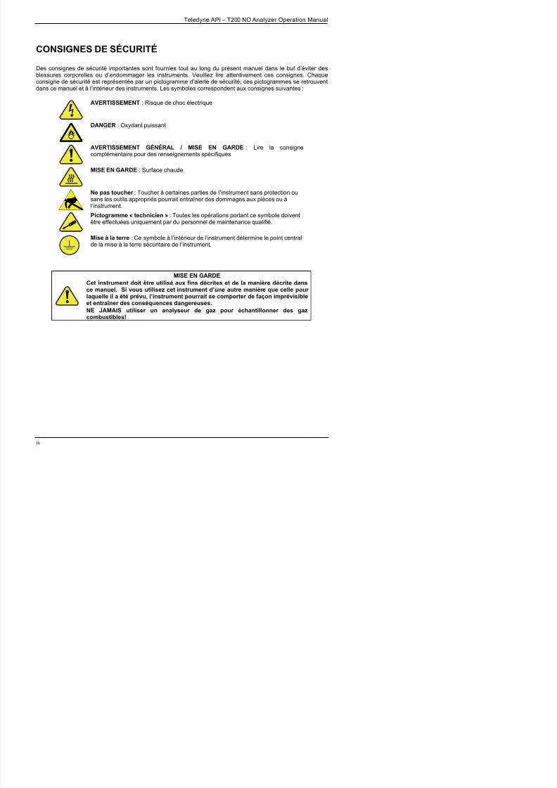
CONSIGNES DE SÉCURITÉ
Des consignes de sécurité importantes sont fournies tout au long du présent manuel dans le but d’éviter desblessures corporelles ou d’endommager les instruments. Veuillez lire attentivement ces consignes. Chaqueconsigne de sécurité est représentée par un pictogramme d’alerte de sécurité; ces pictogrammes se retrouventdans ce manuel et à l’intérieur des instruments. Les symboles correspondent aux consignes suivantes :
AVERTISSEMENT : Risque de choc électrique
DANGER : Oxydant puissant
AVERTISSEMENT GÉNÉRAL / MISE EN GARDE : Lire la consignecomplémentaire pour des renseignements spécifiques
MISE EN GARDE : Surface chaude
Ne pas toucher : Toucher à certaines parties de l’instrument sans protection ousans les outils appropriés pourrait entraîner des dommages aux pièces ou àl’instrument.
Pictogramme « technicien » : Toutes les opérations portant ce symbole doiventêtre effectuées uniquement par du personnel de maintenance qualifié.
Mise à la terre : Ce symbole à l’intérieur de l’instrument détermine le point centralde la mise à la terre sécuritaire de l’instrument.
MISE EN GARDECet instrument doit être utilisé aux fins décrites et de la manière décrite dansce manuel. Si vous utilisez cet instrument d’une autre manière que celle pourlaquelle il a été prévu, l’instrument pourrait se comporter de façon imprévisibleet entraîner des conséquences dangereuses.NE JAMAIS utiliser un analyseur de gaz pour échantillonner des gazcombustibles!

8/9/2019 06858D_T200
http://slidepdf.com/reader/full/06858dt200 7/476
WARRANTYWARRANTY POLICY (02024 F)
Teledyne Advanced Pollution Instrumentation (TAPI), a business unit of Teledyne
Instruments, Inc., provides that:
Prior to shipment, TAPI equipment is thoroughly inspected and tested. Should equipment
failure occur, TAPI assures its customers that prompt service and support will be available.
COVERAGEAfter the warranty period and throughout the equipment lifetime, TAPI stands ready to
provide on-site or in-plant service at reasonable rates similar to those of other manufacturers
in the industry. All maintenance and the first level of field troubleshooting are to be
performed by the customer.
NON-TAPI MANUFACTURED EQUIPMENTEquipment provided but not manufactured by TAPI is warranted and will be repaired to the
extent and according to the current terms and conditions of the respective equipment
manufacturer’s warranty.
PRODUCT RETURNAll units or components returned to Teledyne API should be properly packed for
handling and returned freight prepaid to the nearest designated Service Center. After the
repair, the equipment will be returned, freight prepaid.
The complete Terms and Conditions of Sale can be reviewed at http://www.teledyne-
api.com/terms_and_conditions.asp
CAUTION – Avoid Warranty Invalidation
Failure to comply with proper anti-Electro-Static Discharge (ESD) handling and packing instructionsand Return Merchandise Authorization (RMA) procedures when returning parts for repair orcalibration may void your warranty. For anti-ESD handling and packing instructions please refer to“Packing Components for Return to Teledyne API’s Customer Service” in the Primer on Electro-Static Discharge section of this manual, and for RMA procedures please refer to our Website athttp://www.teledyne-api.com under Customer Support > Return Authorization.

8/9/2019 06858D_T200
http://slidepdf.com/reader/full/06858dt200 8/476
Teledyne API – T200 NO Analyzer Operation Manual
This page intentionally left blank.

8/9/2019 06858D_T200
http://slidepdf.com/reader/full/06858dt200 9/476
ABOUT THIS MANUAL
Presented here is information regarding the documents that are included with this
manual (Structure), its history of release and revisions (Revision History) with a list of
each support document and its revision letter at the time of the initial release of this
manual, how the content is organized (Organization), a description of other information
related to this manual (Related Information), and the conventions used to present the
information in this manual (Conventions Used).
STRUCTURE This T200 manual, PN 06858C, is comprised of multiple documents, assembled in PDF
format, as listed below.
Part No. Rev Name/Description
06858C D Operation Manual, T200 Nitrogen Oxide Analyzer
05295 D Appendix A, Menu Trees and related software documentation
06847 A Spare Parts List (in Appendix B this manual)
04715 D AKIT, Expendables (in Appendix B this manual)
04503 E Appendix C, Repair Questionnaire
069110100 B Interconnect List (in Appendix D this manual)
Schematics (in Appendix D this manual)
06911 B Interconnect Diagram
01669 G SCH, Ozone Gen Driver
04932 C SCH, Thermo-Electric Cooler Driver
03632 C SCH, 0-20mA Driver
03956 A SCH Relay Board
04354 D SCH, Pressure/Flow Transducer Interface
04181 H SCH, PMT Pre-Amplifier Board
04468 B SCH, Analog Output Series Res
04524 E SCH, Relay Board
05803 B SCH, Motherboard, GEN-506698 D SCH, LCD Touch Screen Interface
06882 B SCH, LVDS Transmitter Board
06731 B SCH, Auxilliary-I/O Board

8/9/2019 06858D_T200
http://slidepdf.com/reader/full/06858dt200 10/476
Teledyne API – T200 NO Analyzer Operation Manual
ORGANIZATION
This manual is divided among three main parts and a collection of appendices at the end.
Part I contains introductory information that includes an overview of the analyzer,
specifications, descriptions of the available options, installation and connection
instructions, and the initial calibration and functional checks.
Part II comprises the operating instructions, which include initial functional checks and
calibration, basic, advanced and remote operation, advanced calibration, diagnostics,
testing, and ends with specifics of calibrating for use in EPA monitoring.
Part III provides detailed technical information, starting with maintenance,
troubleshooting and service with Frequently Asked Questions (FAQs), followed by
principles of operation, and a glossary. It also contains a special section dedicated to providing information about electro-static discharge and protecting against its
consequences.
The appendices at the end of this manual provide support information such as, version-
specific software documentation, lists of spare parts and recommended stocking levels,
and schematics.
CONVENTIONS USED
In addition to the safety symbols as presented in the Important Safety Information page,
this manual provides special notices related to the safety and effective use of the
analyzer and other pertinent information.
Special Notices appear as follows:
ATTENTION COULD DAMAGE INSTRUMENT AND VOID WARRANTY
This special notice provides information to avoid damage to yourinstrument and possibly invalidate the warranty.
IMPORTANT IMPACT ON READINGS OR DATA Could either affect accuracy of instrument readings or cause loss of data.
Note Pertinent information associated with the proper care, operation ormaintenance of the analyzer or its parts.

8/9/2019 06858D_T200
http://slidepdf.com/reader/full/06858dt200 11/476
REVISION HISTORY
This section provides information regarding changes to this manual.
T200 Op Manual, PN 06858
Date Rev DCN Change Summary
2013 February 01 D 6646 Correct CE values; misc updates
2012 February 13 C 6213 Technical and Administrative Updates
2011, March 11 B 6018 Administrative Updates
2010 A 5847 Initial Release
The following tabular list captures the Revision of each document included in the T200 Operation Manual at thetime of its initial release:
PN Rev Description
06858C A Operation Manual, T200 Nitrogen Oxide Analyzer
05295 D Appendix A, Menu Trees and related software documentation
06847 A Spare Parts List (in Appendix B this manual)
04414 Q Recommended Spares Stocking Levels (in Appendix B this manual)
04715 D AKIT, Expendables (in Appendix B this manual)
04503 D Appendix C, Repair Questionnaire
06911 A Interconnect Diagram, T200 (in Appendix D this manual)
069110100 A Interconnect List (in Appendix D this manual)
Schematics (in Appendix D this manual)01669 G PCA 016680300, Ozone generator board 04170 with flow meter
04932 C PCA Thermo-electric cooler board
03632 A PCA 03631, 0-20mA Driver
03956 A PCA 039550200, Relay Board
04354 D PCA 04003, Pressure/Flow Transducer Interface
04181 H PCA 041800200, PMT pre-amplifier board
04468 B PCA, 04467, Analog Output Series Res04522 D PCA, Relay, Schematic
04524 D PCB, Relay, Schematic
05803 B SCH, PCA 05802, MOTHERBOARD, GEN-5
06698 D SCH, PCA 06697, INTRFC, LCD TCH SCRN,

8/9/2019 06858D_T200
http://slidepdf.com/reader/full/06858dt200 12/476
TABLE OF CONTENTS
Safety Messages................................................................................................................................................... iii
Warranty................................................................................................................................................................. v About This Manual ............................................................................................................................................... vii Revision History .................................................................................................................................................... ix PART I – GENERAL INFORMATION .................................................................................................................19
1. INTRODUCTION, FEATURES AND OPTIONS ................................................................. 21 1.1. Overview .......................................................................................................................................................21 1.2. Features ........................................................................................................................................................22 1.3. Documentation ..............................................................................................................................................22 1.4. Options..........................................................................................................................................................22
2. SPECIFICATIONS, APPROVALS, & COMPLIANCE ........................................................ 27 2.1. Specifications ................................................................................................................................................27 2.2. EPA Equivalency Designation ......................................................................................................................28 2.3. Approvals and Certifications .........................................................................................................................29
2.3.1. Safety .....................................................................................................................................................29 2.3.2. EMC .......................................................................................................................................................29 2.3.3. Other Type Certifications .......................................................................................................................29
3. GETTING STARTED .......................................................................................................... 31 3.1. Unpacking the T200 Analyzer.......................................................................................................................31
3.1.1. Ventilation Clearance.............................................................................................................................32 3.2. Instrument Layout .........................................................................................................................................33
3.2.1. Front Panel ............................................................................................................................................33 3.2.2. Rear Panel .............................................................................................................................................37 3.2.3. Internal Chassis Layout .........................................................................................................................39
3.3. Connections and Setup.................................................................................................................................41 3.3.1. Electrical Connections ...........................................................................................................................41 3.3.2. Pneumatic Connections .........................................................................................................................55
3.4. Startup, Functional Checks, and Initial Calibration.......................................................................................73
3.4.1. Start Up..................................................................................................................................................73 3.4.2. Warning Messages ................................................................................................................................74 3.4.3. Functional Checks .................................................................................................................................76 3.4.4. Initial Calibration ....................................................................................................................................77 3.4.4.1. Interferents..........................................................................................................................................77
PART II – OPERATING INSTRUCTIONS ..........................................................................................................83
4. OVERVIEW OF OPERATING MODES .............................................................................. 85 4.1. Sample Mode ................................................................................................................................................86
4.1.1. Test Functions .......................................................................................................................................86
4.1.2. Warning Messages ................................................................................................................................89 4.2. Calibration Mode ...........................................................................................................................................90 4.3. Setup Mode...................................................................................................................................................91
4.3.1. Password Security .................................................................................................................................91 4.3.2. Primary Setup Menu ..............................................................................................................................91 4.3.3. Secondary Setup Menu (SETUPMORE) ..........................................................................................92
5. SETUP MENU 93

8/9/2019 06858D_T200
http://slidepdf.com/reader/full/06858dt200 13/476
Teledyne API – T200 NO Analyzer Operation Manual Table of Contents
5.6.2. Adjusting the Internal Clock’s Speed.................................................................................................. 109 5.7. SETUP COMM: Communications Ports................................................................................................ 110
5.7.1. ID (Machine Identification).................................................................................................................. 110 5.7.2. INET (Ethernet)................................................................................................................................... 111
5.7.3. COM1[COM2] (Mode, Baude Rate and Test Port)............................................................................. 111 5.8. SETUP VARS: Variables Setup and Definition..................................................................................... 111 5.9. SETUP Diag: Diagnostics Functions..................................................................................................... 114
5.9.1. Signal I/O ............................................................................................................................................ 116 5.9.2. Analog Output (DIAG AOUT).............................................................................................................. 117 5.9.3. Analog I/O Configuration (DIAG AIO)................................................................................................. 117 5.9.4. Test Chan Output (Selecting a Test Channel Function for Output A4) .............................................. 132 5.9.5. Optic Test............................................................................................................................................ 134 5.9.6. Electrical Test ..................................................................................................................................... 134 5.9.7. Ozone Gen Override........................................................................................................................... 134
5.9.8. Flow Calibration .................................................................................................................................. 134
6. COMMUNICATIONS SETUP AND OPERATION ............................................................ 135 6.1. Data Terminal / Communication Equipment (DTE DEC)........................................................................... 135 6.2. Communication Modes, Baud Rate and Port Testing................................................................................ 135
6.2.1. Communication Modes ....................................................................................................................... 136 6.2.2. Com Port Baud Rate........................................................................................................................... 138 6.2.3. Com Port Testing ................................................................................................................................ 138
6.3. RS-232 ....................................................................................................................................................... 140 6.4. RS-485 (Option) ......................................................................................................................................... 140 6.5. Ethernet...................................................................................................................................................... 141
6.5.1. Configuring Ethernet Communication Manually (Static IP Address) .................................................. 141 6.5.2. Configuring Ethernet Communication Using Dynamic Host Configuration Protocol (DHCP) ............ 143
6.6. USB Port for Remote Access..................................................................................................................... 146 6.7. Communications Protocols ........................................................................................................................ 148
6.7.1. MODBUS ............................................................................................................................................ 148 6.7.2. Hessen................................................................................................................................................ 150
7. DATA ACQUISITION SYSTEM (DAS) AND APICOM..................................................... 159 7.1. DAS Structure ............................................................................................................................................ 160
7.1.1. DAS Channels .................................................................................................................................... 160 7.1.2. Viewing DAS Data and Settings ......................................................................................................... 165 7.1.3. Editing DAS Data Channels................................................................................................................ 166
7.2. Remote DAS Configuration........................................................................................................................ 178 7.2.1. DAS Configuration via APICOM ......................................................................................................... 178 7.2.2. DAS Configuration via Terminal Emulation Programs........................................................................ 180
8. REMOTE OPERATION .................................................................................................... 181 8.1. Computer Mode ......................................................................................................................................... 181
8.1.1. Remote Control via APICOM.............................................................................................................. 181 8.2. Interactive Mode......................................................................................................................................... 182
8.2.1. Remote Control via a Terminal Emulation Program........................................................................... 182 8.3. Remote Access by Modem........................................................................................................................ 184 8.4. Password Security for Serial Remote Communications ............................................................................ 187
9. CALIBRATION PROCEDURES ....................................................................................... 189 9.1. Before Calibration ...................................................................................................................................... 190
9 1 1 R i d E i t S li d E d bl 190

8/9/2019 06858D_T200
http://slidepdf.com/reader/full/06858dt200 14/476
Table of Contents Teledyne API – T200 NO Analyzer Operation Manual
9.3.1. Performing “Precision” Manual Calibration when Internal Span Gas (IZS) Generator Option isPresent.......................................................................................................................................................... 198 9.3.2. Setup for Calibration with the Internal Span Gas Generator .............................................................. 199 9.3.3. CAL On NO2 Feature .......................................................................................................................... 199
9.3.4. Performing a Manual Calibration Check with the Internal Span Gas Generator................................ 201 9.3.5. Performing a Manual Calibration with the Internal Span Gas Generator ........................................... 202 9.4. Manual Calibration and Cal Checks with the Valve Options Installed ....................................................... 205
9.4.1. Setup for Calibration Using Valve Options ......................................................................................... 205 9.4.2. Manual Calibration Checks with Valve Options Installed ................................................................... 206 9.4.3. Manual Calibration Using Valve Options ............................................................................................ 207
9.5. Automatic Zero/Span Cal/Check (AutoCal) ............................................................................................... 209 9.5.1. SETUP ACAL: Programming and AUTO CAL Sequence.............................................................. 212
9.6. Calibration Quality Analysis ....................................................................................................................... 215 9.7. Gas Flow Calibration.................................................................................................................................. 216
10. EPA PROTOCOL CALIBRATION ................................................................................. 217 10.1. T200 Calibration – General Guidelines.................................................................................................... 217 10.2. Calibration Equipment, Supplies, and Expendables................................................................................ 219
10.2.1. Spare Parts and Expendable Supplies............................................................................................. 219 10.2.2. Calibration Gas and Zero Air Sources.............................................................................................. 219 10.2.3. Data Recording Device ..................................................................................................................... 220 10.2.4. Record Keeping ................................................................................................................................ 220
10.3. Calibration Frequency.............................................................................................................................. 220 10.4. Level 1 Calibrations versus Level 2 Checks ............................................................................................ 221 10.5. Gas Phase Titration (GPT)....................................................................................................................... 222
10.5.1. GPT Principle of Operation............................................................................................................... 222 10.5.2. GPT Calibrator Check Procedure..................................................................................................... 222
10.6. GPT Multipoint Calibration Procedure ..................................................................................................... 225 10.6.1. Set Up for GPT Multipoint Calibration of the T200 ........................................................................... 226 10.6.2. Zero Calibration ................................................................................................................................ 227 10.6.3. Span Calibration ............................................................................................................................... 227
10.7. GPT NO2 Check....................................................................................................................................... 228 10.8. Other Quality Assurance Procedures ...................................................................................................... 229
10.8.1. Summary of Quality Assurance Checks ........................................................................................... 229 10.8.2. Short Calibration Checks .................................................................................................................. 230 10.8.3. Zero/Span Check Procedures .......................................................................................................... 231 10.8.4. Precision Check ................................................................................................................................ 231
10.9. Certification of Working Standards .......................................................................................................... 231 10.10. References............................................................................................................................................. 233 PART III – Maintenance and Service................................................................................................................ 235
11. INSTRUMENT MAINTENANCE .................................................................................... 237 11.1. Maintenance Schedule............................................................................................................................. 237
11.2. Predictive Diagnostics.............................................................................................................................. 239 11.3. Maintenance Procedures ......................................................................................................................... 240
11.3.1. Replacing the Sample Particulate Filter............................................................................................ 240 11.3.2. Changing the O3 Dryer Particulate Filter .......................................................................................... 241 11.3.3. Changing the Ozone Cleanser Chemical ......................................................................................... 242 11.3.4. Maintaining the External Sample Pump (Pump Pack)...................................................................... 245 11.3.5. Changing the Pump DFU Filter......................................................................................................... 245

8/9/2019 06858D_T200
http://slidepdf.com/reader/full/06858dt200 15/476
Teledyne API – T200 NO Analyzer Operation Manual Table of Contents
12.1.2. Fault Diagnosis With Test Functions ................................................................................................ 264 12.1.3. DIAG SIGNAL I/O: Using the Diagnostic Signal I/O Function..................................................... 265
12.2. Using the Analog Output Test Channel ................................................................................................... 267 12.3. Using the Internal Electronic Status LEDs............................................................................................... 268
12.3.1. CPU Status Indicator ........................................................................................................................ 268 12.3.2. Relay PCA Status LEDs ................................................................................................................... 268 12.4. Gas Flow Problems.................................................................................................................................. 270
12.4.1. Zero or Low Flow Problems.............................................................................................................. 270 12.5. Calibration Problems................................................................................................................................ 274
12.5.1. Negative Concentrations................................................................................................................... 274 12.5.2. No Response .................................................................................................................................... 275 12.5.3. Unstable Zero and Span................................................................................................................... 275 12.5.4. Inability to Span - No SPAN Button (CALS) ..................................................................................... 276 12.5.5. Inability to Zero - No ZERO Button (CALZ) ...................................................................................... 276 12.5.6. Non-Linear Response ....................................................................................................................... 276 12.5.7. Discrepancy Between Analog Output and Display........................................................................... 278 12.5.8. Discrepancy Between NO and NOX slopes ..................................................................................... 278
12.6. Other Performance Problems .................................................................................................................. 278 12.6.1. Excessive Noise................................................................................................................................ 279 12.6.2. Slow Response ................................................................................................................................. 279 12.6.3. Auto Zero Warnings ......................................................................................................................... 279
12.7. Subsystem Checkout ............................................................................................................................... 280 12.7.1. AC Main Power ................................................................................................................................. 280
12.7.2. DC Power Supply.............................................................................................................................. 281 12.7.3. I
2C Bus .............................................................................................................................................. 282
12.7.4. LCD/Display Module ......................................................................................................................... 283 12.7.5. Relay PCA ........................................................................................................................................ 283 12.7.6. Motherboard...................................................................................................................................... 283 12.7.7. Pressure / Flow Sensor Assembly.................................................................................................... 287 12.7.8. CPU................................................................................................................................................... 288 12.7.9. RS-232 Communications.................................................................................................................. 289 12.7.10. NO2 NO Converter..................................................................................................................... 290
12.7.11. Determining CE by Simplified GPT Calibration .............................................................................. 295 12.7.12. Photomultiplier Tube (PMT) Sensor Module................................................................................... 298 12.7.13. PMT Preamplifier Board.................................................................................................................. 300 12.7.14. PMT Temperature Control PCA...................................................................................................... 301 12.7.15. O3 Generator................................................................................................................................... 302 12.7.16. Internal Span Gas Generator and Valve Options........................................................................... 303 12.7.17. Temperature Sensor....................................................................................................................... 304
12.8. Service Procedures.................................................................................................................................. 306 12.8.1. Disk-On-Module Replacement Procedure........................................................................................ 306 12.8.2. O3 Generator Replacement ..............................................................................................................307 12.8.3. Sample and Ozone (Perma Pure®) Dryer Replacement................................................................... 307 12.8.4. PMT Sensor Hardware Calibration................................................................................................... 308 12.8.5. Replacing the PMT, HVPS or TEC ................................................................................................... 310 12.8.6. Removing / Replacing the Relay PCA from the Instrument.............................................................. 313
12.9. Frequently Asked Questions.................................................................................................................... 314 12.10. Technical Assistance ............................................................................................................................. 316
3

8/9/2019 06858D_T200
http://slidepdf.com/reader/full/06858dt200 16/476
Table of Contents Teledyne API – T200 NO Analyzer Operation Manual
13.2.3. Ozone Gas Generation and Air Flow................................................................................................ 330 13.2.4. Pneumatic Sensors........................................................................................................................... 333
13.3. Electronic Operation................................................................................................................................. 336 13.3.1. Overview ........................................................................................................................................... 336
13.3.2. CPU................................................................................................................................................... 338 13.3.3. Motherboard...................................................................................................................................... 339 13.3.4. Relay PCA ........................................................................................................................................ 344
13.4. Sensor Module, Reaction Cell ................................................................................................................. 350 13.5. Photo Multiplier Tube (PMT) .................................................................................................................... 351
13.5.1. PMT Preamplifier .............................................................................................................................. 352 13.5.2. PMT Cooling System ........................................................................................................................ 354
13.6. Pneumatic Sensor Board ......................................................................................................................... 355 13.7. Power Supply/Circuit Breaker .................................................................................................................. 356
13.7.1. AC Power Configuration ................................................................................................................... 357 13.8. Front Panel Touchscreen/Display Interface............................................................................................. 362
13.8.1. LVDS Transmitter Board................................................................................................................... 363 13.8.2. Front Panel Touchscreen/Display Interface PCA............................................................................. 363
13.9. Software Operation .................................................................................................................................. 363 13.9.1. Adaptive Filter ................................................................................................................................... 364 13.9.2. Temperature/Pressure Compensation (TPC)................................................................................... 364 13.9.3. Calibration - Slope and Offset........................................................................................................... 365
14. A PRIMER ON ELECTRO-STATIC DISCHARGE......................................................... 367 14.1. How Static Charges are Created ............................................................................................................. 367 14.2. How Electro-Static Charges Cause Damage........................................................................................... 368 14.3. Common Myths About ESD Damage ...................................................................................................... 369 14.4. Basic Principles of Static Control ............................................................................................................. 370
14.4.1. General Rules ................................................................................................................................... 370 14.5. Basic anti-ESD Procedures for Analyzer Repair and Maintenance......................................................... 372
14.5.1. Working at the Instrument Rack ....................................................................................................... 372 14.5.2. Working at an Anti-ESD Work Bench ............................................................................................... 372 14.5.3. Transferring Components Between Rack and Bench ...................................................................... 373 14.5.4. Opening Shipments from Teledyne API's Customer Service........................................................... 373
14.5.5. Packing Components for Return to Teledyne API's Customer Service............................................ 374 Glossary ............................................................................................................................................................ 375 Index.................................................................................................................................................................. 379
APPENDIX A - VERSION SPECIFIC SOFTWARE DOCUMENTATIONAPPENDIX B - SPARE PARTSAPPENDIX C - REPAIR QUESTIONNAIRE APPENDIX D - ELECTRONIC SCHEMATICS
FIGURES
Figure 3-1: Front Panel Layout.......................................................................................................................33 Figure 3-2: Display Screen and Touch Control ..............................................................................................34 Figure 3-3: Display/Touch Control Screen Mapped to Menu Charts .............................................................36

8/9/2019 06858D_T200
http://slidepdf.com/reader/full/06858dt200 17/476

8/9/2019 06858D_T200
http://slidepdf.com/reader/full/06858dt200 18/476
Table of Contents Teledyne API – T200 NO Analyzer Operation Manual
Figure 12-10: Relay PCA with AC Relay Retainer In Place............................................................................ 313 Figure 12-11: Relay PCA Mounting Screw Locations .................................................................................... 313 Figure 13-1: Reaction Cell with PMT Tube and Optical Filter ....................................................................... 319 Figure 13-2: T200 Sensitivity Spectrum........................................................................................................ 320
Figure 13-3: NO2 NO Conversion .............................................................................................................. 320 Figure 13-4: Pneumatic Flow During the Auto Zero Cycle............................................................................ 322 Figure 13-7. Vacuum Manifold, Standard Configuration............................................................................... 326 Figure 13-8: Flow Control Assembly & Critical Flow Orifice.......................................................................... 327 Figure 13-9: Location of Flow Control Assemblies & Critical Flow Orifices .................................................. 329 Figure 13-10: Ozone Generator Principle ....................................................................................................... 331 Figure 13-11: Semi-Permeable Membrane Drying Process ........................................................................... 331 Figure 13-12: T200 Perma Pure
® Dryer .......................................................................................................... 332
Figure 13-13: T200 Electronic Block Diagram ................................................................................................ 336 Figure 13-14: CPU Board................................................................................................................................ 338 Figure 13-15: Relay PCA Layout (P/N 045230100) ........................................................................................ 344 Figure 13-16: Relay PCA P/N 045230100 with AC Relay Retainer in Place.................................................. 345 Figure 13-17: Status LED Locations – Relay PCA.......................................................................................... 346 Figure 13-18: Heater Control Loop Block Diagram......................................................................................... 348 Figure 13-19: Thermocouple Configuration Jumper (JP5) Pin-Outs............................................................... 350 Figure 13-20: T200 Sensor Module Assembly................................................................................................ 351 Figure 13-21: Basic PMT Design .................................................................................................................... 352 Figure 13-22: PMT Preamp Block Diagram .................................................................................................... 353 Figure 13-23: Typical Thermo-Electric Cooler ................................................................................................ 354
Figure 13-24: PMT Cooling System Block Diagram........................................................................................ 355 Figure 13-25: Power Distribution Block Diagram ............................................................................................ 357 Figure 13-26: Location of AC power Configuration Jumpers .......................................................................... 358 Figure 13-27: Pump AC Power Jumpers (JP7)............................................................................................... 359 Figure 13-28: Typical Set Up of AC Heater Jumper Set (JP2)........................................................................ 360 Figure 13-29: Typical Jumper Set (JP2) Set Up of Heaters........................................................................... 361 Figure 13-30: Front Panel and Display Interface Block Diagram.................................................................... 362 Figure 13-31: Basic Software Operation......................................................................................................... 363 Figure 14-1: Triboelectric Charging............................................................................................................... 367
Figure 14-2: Basic anti-ESD Workbench....................................................................................................... 370
TABLES
Table 1-1. Analyzer Options..........................................................................................................................23 Table 2-2: Software Settings for EPA Equivalence.......................................................................................28
Table 3-1: Ventilation Clearance...................................................................................................................32 Table 3-5: Analog Output Pin Assignments..................................................................................................43 Table 3-6: Status Output Pin Assignments...................................................................................................46 Table 3-7: Control Input Pin Assignments ....................................................................................................47 Table 3-8: NIST-SRM's Available for Traceability of NOx Calibration Gases ................................................58 Table 3-9: Zero/Span Valves Operating States OPT 50A ............................................................................65 Table 3 10: Valve Operating States OPT 50B installed 69

8/9/2019 06858D_T200
http://slidepdf.com/reader/full/06858dt200 19/476
Teledyne API – T200 NO Analyzer Operation Manual Table of Contents
Table 5-4: Diagnostic Mode (DIAG) Functions .......................................................................................... 114 Table 5-5: DIAG - Analog I/O Functions .................................................................................................... 117 Table 5-6: Analog Output Voltage Range Min/Max ................................................................................... 119 Table 5-7: Voltage Tolerances for the TEST CHANNEL Calibration......................................................... 123
Table 5-8: Current Loop Output Check...................................................................................................... 127 Table 5-9: Test Channels Functions available on the T200’s Analog Output............................................ 132 Table 6-1: COMM Port Communication Modes......................................................................................... 136 Table 6-2: Ethernet Status Indicators......................................................................................................... 141 Table 6-4: RS-232 Communication Parameters for Hessen Protocol ....................................................... 150 Table 6-5: Teledyne API's Hessen Protocol Response Modes ................................................................. 153 Table 6-6: Default Hessen Status Flag Assignments ................................................................................ 157 Table 7-1: Front Panel LED Status Indicators for DAS.............................................................................. 159 Table 7-2: DAS Data Channel Properties.................................................................................................. 161 Table 7-3: DAS Data Parameter Functions ............................................................................................... 169 Table 8-1: Terminal Mode Software Commands ....................................................................................... 182 Table 8-2: Teledyne API's Serial I/O Command Types ............................................................................. 183 Table 9-1: IZS Option Valve States with CAL_ON_NO2 Turned ON......................................................... 199 Table 9-2: AUTOCAL Modes ..................................................................................................................... 209 Table 9-3: AutoCal Attribute Setup Parameters......................................................................................... 210 Table 9-4: Example AutoCal Sequence..................................................................................................... 211 Table 9-5: Calibration Data Quality Evaluation.......................................................................................... 215 Table 10-1: Activity Matrix for EPA Calibration Equipment and Supplies.................................................... 219 Table 10-2: Definition of Level 1 and Level 2 Zero and Span Checks......................................................... 221
Table 10-3: Activity Matrix for Data Quality.................................................................................................. 230 Table 11-1: T200 Maintenance Schedule .................................................................................................... 238 Table 11-2: Predictive Uses for Test Functions ........................................................................................... 239 Table 12-1: Front Panel Warning Messages ............................................................................................... 262 Table 12-2: Test Functions - Indicated Failures........................................................................................... 264 Table 12-3: Test Channel Outputs as Diagnostic Tools .............................................................................. 267 Table 12-4: Relay PCA Watchdog LED Failure Indications......................................................................... 268 Table 12-5: Relay PCA Status LED Failure Indications............................................................................... 269 Table 12-6: DC Power Test Point and Wiring Color Codes......................................................................... 281
Table 12-7: DC Power Supply Acceptable Levels ....................................................................................... 282 Table 12-8: Relay PCA Control Devices...................................................................................................... 283 Table 12-9: Analog Output Test Function - Nominal Values Voltage Outputs ............................................ 284 Table 12-10: Status Outputs Check ............................................................................................................... 286 Table 12-11: T200 Control Input Pin Assignments and Corresponding Signal I/O Functions....................... 286 Table 13-1: List of Interferents ..................................................................................................................... 324 Table 13-2: T200 Valve Cycle Phases......................................................................................................... 327 Table 13-3: T200 Gas Flow Rates ............................................................................................................... 329 Table 13-4: Relay PCA Status LED’s........................................................................................................... 346 Table 13-5: Thermocouple Configuration Jumper (JP5) Pin-Outs............................................................... 349 Table 13-6: AC Power Configuration for Internal Pumps (JP7) ................................................................... 359 Table 13-7: Power Configuration for Standard AC Heaters (JP2) ............................................................... 360 Table 13-8: Power Configuration for Optional Heaters (JP6) ...................................................................... 361 Table 14-1: Static Generation Voltages for Typical Activities...................................................................... 368 Table 14-2: Sensitivity of Electronic Devices to Damage by ESD............................................................... 368

8/9/2019 06858D_T200
http://slidepdf.com/reader/full/06858dt200 20/476
Table of Contents Teledyne API – T200 NO Analyzer Operation Manual
This page intentionally left blank.

8/9/2019 06858D_T200
http://slidepdf.com/reader/full/06858dt200 21/476
PART I –
GENERAL INFORMATION

8/9/2019 06858D_T200
http://slidepdf.com/reader/full/06858dt200 22/476

8/9/2019 06858D_T200
http://slidepdf.com/reader/full/06858dt200 23/476
1. INTRODUCTION, FEATURES AND OPTIONS
1.1. OVERVIEWThe Model T200 (also referred to as T200) Nitrogen Oxides Analyzer uses
chemiluminescence detection, coupled with state-of-the-art microprocessor technology
to provide the sensitivity, stability and ease of use needed for ambient or dilution CEM
monitoring requirements of nitric oxide (NO), nitrogen dioxide (NO2) and the total
nitrogen oxides (NOx). The instrument:
Calculates the amount of NO present by measuring the amount of
chemiluminescence given off when the sample gas is exposed to ozone (O3). Uses a catalytic-reactive converter to convert any NO2 in the sample gas to
NO, which is then measured as above (including the original NO in the samplegas) and reported as NOx.
Since the density of the sample gas effects the brightness of the chemiluminescence
reaction, the T200 software compensates for temperature and pressure changes.
Stability is further enhanced by an Auto-Zero feature which periodically redirects the
gas flow through the analyzer so that no chemiluminescence reaction is present in thesample chamber. The analyzer measures this “dark” condition and uses the results as an
offset, which is subtracted from the sensor readings recorded while the instrument is
measuring NO and NOX. The result gives a sensitive, accurate, and dependable
performance under the harshest operating conditions.
The T200 analyzer’s multi-tasking software gives the ability to track and report a large
number of operational parameters in real time. These readings are compared to
diagnostic limits kept in the analyzers memory and should any fall outside of those
limits the analyzer issues automatic warnings.
Built-in data acquisition capability, using the analyzer's internal memory, allows the
logging of multiple parameters including averaged or instantaneous concentration
values, calibration data, and operating parameters such as pressure and flow rate. Stored
data are easily retrieved through the rear panel serial or Ethernet ports via our APICOM
Introduction Features and Options Teledyne API T200 NO Analyzer Operation Manual

8/9/2019 06858D_T200
http://slidepdf.com/reader/full/06858dt200 24/476
Introduction, Features and Options Teledyne API – T200 NO Analyzer Operation Manual
1.2. FEATURESSome of the other exceptional features of your T200 Nitrogen Oxides Analyzer are:
Ranges, 0-50 ppb to 0-20 ppm, user selectable
Independent ranges and auto ranging
Large, vivid, and durable graphics display with touch screen interface
Microprocessor controlled for versatility
Multi-tasking software to allow viewing test variables while operating
Continuous self checking with alarms
Permeation dryer on ozone generator
Bi-directional RS-232, optional USB and RS-485, and 10/100Base-T Ethernetports for remote operation
Front panel USB ports for peripheral devices and firmware upgrades
Digital status outputs to provide instrument operating condition
Adaptive signal filtering to optimize response time
Temperature and pressure compensation
Converter efficiency correction software
Catalytic ozone destruct
Comprehensive internal data logging with programmable averaging periods
Ability to log virtually any operating parameter
8 analog inputs (optional)
Internal zero and span check (optional)
1.3. DOCUMENTATIONIn addition to this operation manual (part number 06858), two other manuals are
available for download from Teledyne API’s website at http://www.teledyne-
api.com/manuals/, to support the operation of the instrument:
APICOM Software Manual, part number 03945
DAS Manual, part number 02837
1.4. OPTIONSThe options available for your analyzer are present in with name, option number, a
description and/or comments, and if applicable, cross-references to technical details in this
manual, such as setup and calibration. To order these options or to learn more about them,
please contact the Sales Department of Teledyne Advanced Pollution Instruments at:
Teledyne API – T200 NO Analyzer Operation Manual Introduction Features and Options

8/9/2019 06858D_T200
http://slidepdf.com/reader/full/06858dt200 25/476
Teledyne API T200 NO Analyzer Operation Manual Introduction, Features and Options
Table 1-1. Analyzer Options
OptionOptionNumber
Description/Notes Reference
Pumps Pumps meet all typical AC power supply standards while exhibiting samepneumatic performance.
11A Ship without pump N/A
11B Pumpless Pump Pack N/A
12A Internal Pump 115V @ 60 Hz N/A
12B Internal Pump 220V @ 60 Hz N/A
12C Internal Pump 220V @ 50 Hz N/A
Rack MountKits Options for mounting the analyzer in standard 19” racks
20A Rack mount brackets with 26 in. (660 mm) chassis slides N/A
20B Rack mount brackets with 24 in. (610 mm) chassis slides N/A
21 Rack mount brackets only (compatible with carrying strap, Option 29) N/A
23 Rack mount for external pump pack (no slides) N/A
Carrying Strap/Handle Side-mounted strap for hand-carrying analyzer
29
Extends from “flat” position to accommodate hand for carrying.
Recesses to 9mm (3/8”) dimension for storage.Can be used with rack mount brackets, Option 21.
Cannot be used with rack mount slides.
N/A
CAUTION – GENERAL SAFETY HAZARD
THE T200 ANALYZER WEIGHS ABOUT 18 KG (40 POUNDS).
TO AVOID PERSONAL INJURY WE RECOMMEND THAT TWO PERSONS LIFT AND CARRY THEANALYZER. DISCONNECT ALL CABLES AND TUBING FROM THE ANALYZER BEFORE MOVING IT.
Analog Input and USB portUsed for connecting external voltage signals from other instrumentation (such asmeteorological instruments).
64B Also can be used for logging these signals in the analyzer’s internalDAS
Sections 3.3.1.2,and 7
Current Loop AnalogOutputs
Adds isolated, voltage-to-current conversion circuitry to the analyzer’s analogoutputs.
41
Can be configured for any output range between 0 and 20 mA.
May be ordered separately for any of the analog outputs.
Can be installed at the factory or retrofitted in the field.
Sections 3.3.1.4 and 5.9.3.7
Parts Kits Spare parts and expendables
42AExpendables Kit includes a recommended set of expendables forone year of operation of this instrument including replacementsample particulate filters.
Appendix B
43Expendables Kit with IZS includes the items needed to refurbish
A di B
Introduction, Features and Options Teledyne API – T200 NO Analyzer Operation Manual

8/9/2019 06858D_T200
http://slidepdf.com/reader/full/06858dt200 26/476
Introduction, Features and Options Teledyne API T200 NO Analyzer Operation Manual
OptionOptionNumber
Description/Notes Reference
Calibration ValvesUsed to control the flow of calibration gases generated from external sources,
rather than manually switching the rear panel pneumatic connections.
50AAMBIENT ZERO AND AMBIENT SPAN VALVESZero Air and Span Gas input supplied at ambient pressure.
Gases controlled by 2 internal valves; SAMPLE/CAL & ZERO/SPAN. Section 3.3.2.3
50B
AMBIENT ZERO AND PRESSURIZED SPAN VALVESSpan Gas input from external, pressurized source;
Span Gas flow rate maintained at 1 ATM by critical flow orifice & ventedthrough Vent port.
Shutoff valve stops flow of Span Gas when in sample mode to preservepressurized gas source.
Zero Air created via 2-stage scrubber & dry filter unit (DFU).Gases controlled by 2 internal valves; SAMPLE/CAL & ZERO/SPAN.
Section 3.3.2.4
50G
ZERO SCRUBBER AND INTERNAL SPAN SOURCE (IZS)Span Gas generated from internal NO2 permeation tube
Zero Air created by 2-stage scrubber & DFU.
Gases controlled by 2 internal valves: Sample/Cal & Zero/Span.
Sections 3.3.2.5 and 3.3.2.6
NO2 Permeation Tubes Replacement tubes; identical size/shape; different permeation rates.
Permeation Rate
( 25%) Approximate NO2 Concentration @ 50°C
52B 421 ng/min 300ppb – 500 ppb 25% N/A
52G 842 ng/min 0600 – 1000 ppb 25% N/A
Each tube comes with a calibration certificate, traceable to a NIST standard,specifying its actual effusion rate of that tube to within ± 5% @ 0.56 liters perminute, calibration performed at a tube temperature of 50°C.
Section 3.3.2.5
Communication Cables For remote serial, network and Internet communication with the analyzer.
Type Description
60A RS-232
Shielded, straight-through DB-9F to DB-25M cable, about
1.8 m long. Used to interface with older computers orcode activated switches with DB-25 serial connectors.
Section 3.3.1.8
60B RS-232Shielded, straight-through DB-9F to DB-9F cable of about1.8 m length.
Section 3.3.1.8
60C EthernetPatch cable, 2 meters long, used for Internet and LANcommunications.
Section 3.3.1.8
60D USBCable for direct connection between instrument (rearpanel USB port) and personal computer.
Section 3.3.1.8
USB Port For remote connection
64AFor connection to personal computer. (Separate option only whenOption 64B, Analog Input and USB Com Port not elected).
Sections 3.3.1.8 and 6.6
Concentration Alarm Relays Issues warning when gas concentration exceeds limits set by user.
61Four (4) “dry contact” relays on the rear panel of the instrument. Thisrelay option is different from and in addition to the “Contact Closures”that come standard on all TAPI instruments
Section 3.3.1.7
Teledyne API – T200 NO Analyzer Operation Manual Introduction, Features and Options

8/9/2019 06858D_T200
http://slidepdf.com/reader/full/06858dt200 27/476
y y p , p
OptionOptionNumber
Description/Notes Reference
Other Gas Options Second gas sensor and gas conditioners
65A Oxygen (O2) Sensor Figure 3-6
86A Ammonia removal sample conditioner (required for EN Certification) 3.3.2.6, 3.4.4.1
86C External zero air scrubberSections 3.3.2.6,9.1.2.1, 11.3.7, and11.3.7.1, Table 11-1
Special Features Built in features, software activated
N/A
Maintenance Mode Switch, located inside the instrument, placesthe analyzer in maintenance mode where it can continue sampling,yet ignore calibration, diagnostic, and reset instrument commands.This feature is of particular use for instruments connected toMultidrop or Hessen protocol networks.
Call Customer Service for activation.
N/A
N/A
Second Language Switch activates an alternate set of displaymessages in a language other than the instrument’s defaultlanguage.
Call Customer Service for a specially programmed Disk on Module containingthe second language.
N/A
N/A
Dilution Ratio Option allows the user to compensate for diluted
sample gas, such as in continuous emission monitoring (CEM) wherethe quality of gas in a smoke stack is being tested and the samplingmethod used to remove the gas from the stack dilutes the gas.
Call Customer Service for activation.
Section 5.4.3.5
Introduction, Features and Options Teledyne API – T200 NO Analyzer Operation Manual

8/9/2019 06858D_T200
http://slidepdf.com/reader/full/06858dt200 28/476
This page intentionally left blank.

8/9/2019 06858D_T200
http://slidepdf.com/reader/full/06858dt200 29/476
2. SPECIFICATIONS, APPROVALS, & COMPLIANCE
This section presents specifications for the T200, Agency approvals, EPA designation,
and CE mark and safety compliance..
2.1. SPECIFICATIONSTable 2-1 presents the instrument’s parameters and the specifications that each meets.
Table 2-1: T200 Basic Unit Specifications
Parameter Specification
Min/Max Range(Physical Analog Output)
Min: 0-50 ppb Full ScaleMax: 0-20,000 ppb Full Scale (selectable, independent NO, NO2, NOx ranges andauto ranges supported)
Measurement Units ppb, ppm, µg/m3, mg/m
3 (selectable)
Zero Noise1 < 0.2 ppb (RMS)
Span Noise1 < 0.5% of reading (RMS) above 50 ppb
or 0.2 ppb, whichever is greater
Lower Detectable Limit2 0.4 ppb
Zero Drift < 0.5 ppb (at constant temperature and voltage) /24 hours
Span Drift < 0.5% of Full Scale (at constant temperature and voltage) /24 hours
Lag Time1
20 seconds
Rise/Fall Time1 <60 seconds to 95%
Linearity 1% of full scale / 24 hours
Precision 0.5% of reading above 50 ppb
Sample Flow Rate 500 cm3/min ± 10%
AC Power 100-120 V, 60 Hz (3.0 A); 220-240 V, 50 Hz (2.5 A)
Power, Ext Pump 100 V, 50/60 Hz (3.25 A); 115 V, 60 Hz (3.0 A);220-240 V, 50/60 Hz (2.5 A)
Analog Output Ranges10V, 5V, 1V, 0.1V (selectable)All Ranges with 5% Under/Over Range
Specifications, Approvals, & Compliance Teledyne API – T200 NO Analyzer Operation Manual

8/9/2019 06858D_T200
http://slidepdf.com/reader/full/06858dt200 30/476
Parameter SpecificationStandard I/O 1 Ethernet: 10/100Base-T
2 RS-232 (300 – 115,200 baud)
2 USB device ports8 opto-isolated digital status outputs (7 defined, 1 spare)
6 opto-isolated digital control inputs (4 defined, 2 spar)
4 analog outputs
Optional I/O 1 USB com port
1 RS485
8 analog inputs (0-10V, 12-bit)
4 digital alarm outputs
Multidrop RS232
3 4-20mA current outputsDimensions H x W x D 7" x 17" x 23.5" (178mm x 432 mm x 597 mm)
Weight Analyzer: 40 lbs (18 kg)
External Pump Pack: 15 lbs (7 kg)
Operating Temperature Range 5 - 40 C (with EPA equivalency)
Humidity Range 0-95% RH non-condensing
Environmental Conditions Installation Category (Over voltage Category) II Pollution Degree 21 As defined by the US EPA.
2
Defined as twice the zero noise level by the US EPA.
2.2. EPA EQUIVALENCY DESIGNATIONTeledyne API’s T200 nitrogen oxides analyzer is designated as a reference method
(Number RFNA-1104-099) for NO2 measurement, as defined in 40 CFR Part 53, when
operated under the following conditions:
Range: Any full-scale range between 0-0.05 and 0-1.0 ppm (parts per million).
Ambient temperature range of 5 to 40°C.
With 1-micron PTFE filter element installed in the internal filter assembly.
Equipped with ozone supply air filter
Gas flow supplied by External vacuum pump capable of 10 in-Hg-A at 2 standardliters per minute (slpm) or better.
Software Settings, see Table 2-2:
Table 2-2: Software Settings for EPA Equivalence
Parameter Setting
Dynamic Zero OFF or ON
Dynamic Span OFF
CAL-on-NO2 OFF
Teledyne API – T200 NO Analyzer Operation Manual Specifications , Approvals, & Compliance

8/9/2019 06858D_T200
http://slidepdf.com/reader/full/06858dt200 31/476
Under the designation, the Analyzer may be operated with or without the following
options:
Rack mount with or without slides.
Rack mount for external pump.
4-20mA isolated analog outputs.
Zero/Span Valves option.
Internal Zero/Span (IZS) option with:
NO2 permeation tube - 0.4 ppm at 0.7 liter per minute; certified/uncertified (notavailable from Teledyne API).
NO2 permeation tube - 0.8 ppm at 0.7 liter per minute; certified/uncertified (not
available from Teledyne API).
Note Under the designation, the IZS option cannot be used as the source ofcalibration.
2.3. APPROVALS AND CERTIFICATIONSThe Teledyne API Model T200 analyzer was tested and certified for Safety and
Electromagnetic Compatibility (EMC). This section presents the compliance statements
for those requirements and directives.
2.3.1. SAFETY
IEC 61010-1:2001, Safety requirements for electrical equipment for measurement,control, and laboratory use.
CE: 2006/95/EC, Low-Voltage Directive
North American: cNEMKO (Canada): CAN/CSA-C22.2 No. 61010-1-04NEMKO-CCL (US): UL No. 61010-1 (2nd Edition)
2.3.2. EMCEN 61326-1 (IEC 61326-1), Class A Emissions/Industrial Immunity
EN 55011 (CISPR 11), Group 1, Class A Emissions
FCC 47 CFR Part 15B, Class A Emissions
CE: 2004/108/EC, Electromagnetic Compatibility Directive
2.3.3. OTHER TYPE CERTIFICATIONS
Specifications, Approvals, & Compliance Teledyne API – T200 NO Analyzer Operation Manual

8/9/2019 06858D_T200
http://slidepdf.com/reader/full/06858dt200 32/476
This page intentionally left blank.

8/9/2019 06858D_T200
http://slidepdf.com/reader/full/06858dt200 33/476
3. GETTING STARTED
This section addresses the procedures for unpacking the instrument and inspecting for
damage, presents clearance specifications for proper ventilation, introduces theinstrument layout, then presents the procedures for getting started: making electrical and
pneumatic connections, and conducting an initial calibration check.
3.1. UNPACKING THE T200 ANALYZER
CAUTIONGENERAL SAFETY HAZARD
To avoid personal injury, always use two persons to lift and carry the T200.
ATTENTION COULD DAMAGE INSTRUMENT AND VOID WARRANTYPrinted Circuit Assemblies (PCAs) are sensitive to electro-static
discharges too small to be felt by the human nervous system. Failure touse ESD protection when working with electronic assemblies will voidthe instrument warranty. Refer to Section 14 for more information onpreventing ESD damage.
CAUTION!Do not operate this instrument until you’ve removed dust plugs from SAMPLEand EXHAUST ports on the rear panel.
Getting Started Teledyne API – T200 NO Analyzer Operation Manual

8/9/2019 06858D_T200
http://slidepdf.com/reader/full/06858dt200 34/476
Verify that there is no apparent external shipping damage. If damage has occurred,
please advise the shipper first, then Teledyne API.
Included with your analyzer is a printed record of the final performance characterization
performed on your instrument at the factory. This record, titled Final Test andValidation Data Sheet (P/N 04490) is an important quality assurance and calibration
record for this instrument. It should be placed in the quality records file for this
instrument.
With no power to the unit, carefully removed the top cover of the analyzer and check for
internal shipping damage by carrying out the following steps:
1. Carefully remove the top cover of the analyzer and check for internal shipping
damage.2. Remove the setscrew located in the top, center of the Front panel.
3. Slide the cover backwards until it clears the analyzer’s front bezel.
4. Lift the cover straight up.
5. Inspect the interior of the instrument to ensure all circuit boards and othercomponents are in good shape and properly seated.
6. Check the connectors of the various internal wiring harnesses and pneumatic hosesto ensure they are firmly and properly seated.
7. Verify that all of the optional hardware ordered with the unit has been installed.These are listed on the paperwork accompanying the analyzer.
WARNING – ELECTRICAL SHOCK HAZARD
Never disconnect PCAs, wiring harnesses or electronic subassemblieswhile under power.
3.1.1. VENTILATION CLEARANCEWhether the analyzer is set up on a bench or installed into an instrument rack, be sure to
leave sufficient ventilation clearance.
Table 3-1: Ventilation Clearance
AREAMINIMUM REQUIRED
CLEARANCE
Back of the instrument 10 cm / 4 in
Teledyne API – T200 NO Analyzer Operation Manual Getting Started

8/9/2019 06858D_T200
http://slidepdf.com/reader/full/06858dt200 35/476
3.2. INSTRUMENT LAYOUTInstrument layout shows front panel and display, rear panel connectors, and internal
chassis layout.
3.2.1. FRONT PANELFigure 3-1 shows the analyzer’s front panel layout, followed by a close-up of the display
screen in Figure 3-2, which is described in Table 3-2. The two USB ports on the front
panel are provided for the connection of peripheral devices:
plug-in mouse (not included) to be used as an alternative to the touchscreen
interface thumb drive (not included) to download updates to instruction software (contact
TAPI Customer Service for information).
Figure 3-1: Front Panel Layout
Getting Started Teledyne API – T200 NO Analyzer Operation Manual

8/9/2019 06858D_T200
http://slidepdf.com/reader/full/06858dt200 36/476
Figure 3-2: Display Screen and Touch Control
The front panel liquid crystal display screen includes touch control. Upon analyzer start-
up, the screen shows a splash screen and other initialization indicators before the maindisplay appears, similar to Figure 3-2 above. The LEDs on the display screen indicate
the Sample, Calibration and Fault states; also on the screen is the gas concentration field
(Conc), which displays real-time readouts for the primary gases, NO, NO2, and NOx, and
for the secondary gas if installed. The display screen also shows what mode the analyzer
is currently in, as well as messages and data (Param). Along the bottom of the screen is a
row of touch control buttons; only those that are currently applicable will have a label.
Table 3-2 provides detailed information for each component of the screen.
ATTENTION COULD DAMAGE INSTRUMENT AND VOID WARRANTYDo not use hard-surfaced instruments such as pens to touch the controlbuttons
Teledyne API – T200 NO Analyzer Operation Manual Getting Started

8/9/2019 06858D_T200
http://slidepdf.com/reader/full/06858dt200 37/476
Table 3-2: Display Screen and Touch Control Description
Field Description/Function
LEDs indicating the states of Sample, Calibration and Fault, as follows:
Name Color State Definition
SAMPLE Green
Off
On
Blinking
Unit is not operating in sample mode, DAS is disabled.
Sample Mode active; Front Panel Display being updated; DAS databeing stored.
Unit is operating in sample mode, front panel display being updated,DAS hold-off mode is ON, DAS disabled
CAL Yellow
Off
On
Blinking
Auto Cal disabled
Auto Cal enabled
Unit is in calibration mode
Status
FAULT RedOff
Blinking
No warnings exist
Warnings exist
ConcDisplays the actual concentration of the sample gas currently being measured by the analyzer in thecurrently selected units of measure.
Mode Displays the name of the analyzer’s current operating mode
ParamDisplays a variety of informational messages such as warning messages, operational data, test functionvalues and response messages during interactive tasks.
Control Buttons Displays dynamic, context sensitive labels on each button, which is blank when inactive until applicable.
Figure 3-3 shows how the front panel display is mapped to the menu charts illustrated in
this manual. The Mode, Param (parameters), and Conc (gas concentration) fields in the
display screen are represented across the top row of each menu chart. The eight touch
control buttons along the bottom of the display screen are represented in the bottom
row of each menu chart.
Getting Started Teledyne API – T200 NO Analyzer Operation Manual

8/9/2019 06858D_T200
http://slidepdf.com/reader/full/06858dt200 38/476
Figure 3-3: Display/Touch Control Screen Mapped to Menu Charts
Note The menu charts in this manual contain condensed representations of theanalyzer’s display during the various operations being described. Thesemenu charts are not intended to be exact visual representations of the
Teledyne API – T200 NO Analyzer Operation Manual Getting Started

8/9/2019 06858D_T200
http://slidepdf.com/reader/full/06858dt200 39/476
3.2.2. REAR PANEL
Figure 3-4: Rear Panel Layout – Base Unit
Table 3-3 provides a description of each component on the rear panel.
Getting Started Teledyne API – T200 NO Analyzer Operation Manual

8/9/2019 06858D_T200
http://slidepdf.com/reader/full/06858dt200 40/476
Table 3-3: Rear Panel Description
Component Function
cooling fan Pulls ambient air into chassis through side vents and exhausts through rear.
AC powerconnector
Connector for three-prong cord to apply AC power to the analyzer.
CAUTION! The cord’s power specifications (specs) MUST comply with the powerspecs on the analyzer’s rear panel Model number label
Model/specs label Identifies the analyzer model number and provides power specs
TO CONV (not used)
FROM CONV (not used)
MULTI (not used)
TO DRYER (not used)
FROM DRYER Outlet for internal sample gas dryer; connect to external zero air scrubber (for IZS optionsonly).
SAMPLEConnect a gas line from the source of sample gas here.
Calibration gases can also enter here on units without zero/span/shutoff valve optionsinstalled.
EXHAUST
Connect an exhaust gas line of not more than 10 meters long here that leads outside the
shelter or immediate area surrounding the instrument. The line must be ¼” tubing orgreater.
SPAN 1 On units with zero/span/shutoff valves option installed, connect a gas line to the source ofcalibrated span gas here.
SPAN2/VENT On units with pressurized span valve option, used for venting.
ZERO AIR Internal Zero Air: On units with zero/span/shutoff valves option installed but no internalzero air scrubber attach a gas line to the source of zero air here.
RX TX LEDs indicate receive (RX) and transmit (TX) activity on the when blinking.
COM 2 Serial communications port for RS-232 or RS-485.
RS-232 Serial communications port for RS-232 only.
DCE DTE Switch to select either data terminal equipment or data communication equipment duringRS-232 communication.
STATUS For ouputs to devices such as Programmable Logic Controllers (PLCs).
ANALOG OUT For voltage or current loop outputs to a strip chart recorder and/or a data logger.
CONTROL IN For remotely activating the zero and span calibration modes.
ALARM Option for concentration alarms and system warnings.
ETHERNET Connector for network or Internet remote communication, using Ethernet cable
ANALOG IN Option for external voltage signals from other instrumentation and for logging thesesignals
USB Connector for direct connection to laptop computer using USB cable
Teledyne API – T200 NO Analyzer Operation Manual Getting Started

8/9/2019 06858D_T200
http://slidepdf.com/reader/full/06858dt200 41/476
3.2.3. INTERNAL CHASSIS LAYOUTFigure 3-5 and Figure 3-6 show internal chassis configurations with different options.
Getting Started Teledyne API – T200 NO Analyzer Operation Manual

8/9/2019 06858D_T200
http://slidepdf.com/reader/full/06858dt200 42/476
Teledyne API – T200 NO Analyzer Operation Manual Getting Started

8/9/2019 06858D_T200
http://slidepdf.com/reader/full/06858dt200 43/476
3.3. CONNECTIONS AND SETUPThis section presents the electrical (Section 3.3.1) and pneumatic (Section 3.3.2)
connections for setup and preparing for instrument operation.
3.3.1. ELECTRICAL CONNECTIONS
Note To maintain compliance with EMC standards, it is required that the cablelength be no greater than 3 meters for all I/O connections, which includeAnalog In, Analog Out, Status Out, Control In, Ethernet/LAN, USB, RS-232,
and RS-485.
This section presents the electrical connections for AC power and communications.
3.3.1.1. CONNECTING POWER
Attach the power cord to the analyzer and plug it into a power outlet capable of carrying
at least 10 A current at your AC voltage and that it is equipped with a functioning earth
ground.
WARNINGELECTRICAL SHOCK HAZARD
High Voltages are present inside the analyzers case.
Power connection must have functioning ground connection.
Do not defeat the ground wire on power plug.
Turn off analyzer power before disconnecting orconnecting electrical subassemblies.
Do not operate with cover off.
CAUTIONGENERAL SAFETY HAZARD
The T200 analyzer can be configured for both100-130 V and 210-240 V at either 47 or 63 Hz.
To avoid damage to your analyzer ensure that the AC power voltage
Getting Started Teledyne API – T200 NO Analyzer Operation Manual

8/9/2019 06858D_T200
http://slidepdf.com/reader/full/06858dt200 44/476
3.3.1.2. CONNECTING ANALOG INPUTS (OPTION)
The Analog In connector is used for connecting external voltage signals from other
instrumentation (such as meteorological instruments) and for logging these signals in the
analyzer’s internal DAS. The input voltage range for each analog input is 0-10 VDC andinput impedance is nominally 20k Ω in parallel with 0.1µF.
Figure 3-7: Analog In Connector
Pin assignments for the Analog In connector are presented in Table 3-4.
Table 3-4: Analog Input Pin Assignments
PIN DESCRIPTION DASPARAMETER1
1 Analog input # 1 AIN 1
2 Analog input # 2 AIN 2
3 Analog input # 3 AIN 3
4 Analog input # 4 AIN 4
5 Analog input # 5 AIN 5
6 Analog input # 6 AIN 6
7 Analog input # 7 AIN 7
8 Analog input # 8 AIN 8
GND Analog input Ground N/A1 See Section 7 for details on setting up the DAS.
3.3.1.3. CONNECTING ANALOG OUTPUTS
The T200 is equipped with several analog output channels accessible through a
connector on the back panel of the instrument.
Output channels A1, A2 and A3 are assigned to the NOx, NO and NO2 concentration
signals of the analyzer.
The default analog output voltage setting of these channels is 0 to 5 VDC with ati f 0 t 500 b
Teledyne API – T200 NO Analyzer Operation Manual Getting Started

8/9/2019 06858D_T200
http://slidepdf.com/reader/full/06858dt200 45/476
There is no optional Current Loop output available for Channel A4.
To access these signals attach a strip chart recorder and/or data-logger to the appropriate
analog output connections on the rear panel of the analyzer. Pin-outs for the analog
output connector are:
ANALOG OUT
A1 A2 A3 A4
+ - + - + - + -
Figure 3-8: Analog Output Connector
Table 3-5: Analog Output Pin Assignments
PIN ANALOG OUTPUT SIGNALSTANDARD
VOLTAGE OUTPUTCURRENT
LOOP OPTION
1 V Out I Out +2 A1 NOx Concentration
Ground I Out -
3 V Out I Out +
4A2 NO Concentration
Ground I Out -
3 V Out I Out +
4A3 NO2 Concentration
Ground I Out -
7 V Out Not Available
8A41 TEST CHANNEL
Ground Not Available
To change the settings for the analog output channels, see Section 5.9.2.
3.3.1.4. CURRENT LOOP ANALOG OUTPUTS (OPTION 41) SETUP
If your analyzer had this option installed at the factory, there are no further connectons
to be made. Otherwise, it can be installed as a retrofit for each of the analog outputs of
the analyzer . This option converts the DC voltage analog output to a current signal with0-20 mA output current. The outputs can be scaled to any set of limits within that 0-20
mA range. However, most current loop applications call for either 2-20 mA or 4-20 mA
range. All current loop outputs have a +5% over-range. Ranges with the lower limit set
to more than 1 mA (e.g., 2-20 or 4-20 mA) also have a -5% under-range.
Fi 3 9 id i ll i i i d ill l bi i f
Getting Started Teledyne API – T200 NO Analyzer Operation Manual

8/9/2019 06858D_T200
http://slidepdf.com/reader/full/06858dt200 46/476
Figure 3-9: Current Loop Option Installed on the Motherboard
CONVERTING CURRENT LOOP ANALOG OUTPUTS TO STANDARD VOLTAGE
OUTPUTS
CAUTION – AVOID INVALIDATING WARRANTY
Servicing or handling of circuit components requires electrostaticdischarge protection, i.e. ESD grounding straps, mats and containers.Failure to use ESD protection when working with electronic assemblies willvoid the instrument warranty. Refer to Section 14 for more information onpreventing ESD damage.
Teledyne API – T200 NO Analyzer Operation Manual Getting Started
4 R th h ldi th t l ti t th th b d

8/9/2019 06858D_T200
http://slidepdf.com/reader/full/06858dt200 47/476
4. Remove the screw holding the current loop option to the motherboard.
5. Disconnect the current loop option PCA from the appropriate connector on themotherboard (see Figure 3-9).
6. Each connector, J19 and J23, requires two shunts. Place one shunt on the two leftmost pins and the second shunt on the two adjacent pins (see Figure 3-9).
7. Reattach the top case to the analyzer.
The analyzer is now ready to have a voltage-sensing, recording device attached to that
output.
Calibrate the analog output as described in Section 5.9.3.2.
3.3.1.5. CONNECTING THE STATUS OUTPUTS
The status outputs report analyzer conditions via optically isolated NPN transistors,
which sink up to 50 mA of DC current. These outputs can be used interface with
devices that accept logic-level digital inputs, such as Programmable Logic Controllers
(PLCs). Each Status bit is an open collector output that can withstand up to 40 VDC.
All of the emitters of these transistors are tied together and available at pin D.
ATTENTION COULD DAMAGE INSTRUMENT AND VOID WARRANTYMost PLC’s have internal provisions for limiting the current that the inputwill draw from an external device. When connecting to a unit that doesnot have this feature, an external dropping resistor must be used to limitthe current through the transistor output to less than 50 mA. At 50 mA,the transistor will drop approximately 1.2V from its collector to emitter.
The status outputs are accessed via a 12-pin connector on the analyzer’s rear panel
labeled STATUS (Figure 3-4). Pin-outs for this connector are:
STATUS
1 2 3 4 5 6 7 8 D +
S Y S T E M
O K
H I G H
R A N G E
C O N C
V A L I D
Z E R O
C A L
S P A N
C A L
D I A G
M O D E
O 2
C A L
Getting Started Teledyne API – T200 NO Analyzer Operation Manual
Table 3 6: Status Output Pin Assignments

8/9/2019 06858D_T200
http://slidepdf.com/reader/full/06858dt200 48/476
Table 3-6: Status Output Pin Assignments
OUTPUT # STATUS DEFINITION CONDITION
1 SYSTEM OK On if no faults are present.
2 CONC VALID On if O3 concentration measurement is valid.If the O3 concentration measurement is invalid, this bit is OFF.
3 HIGH RANGE On if unit is in high range of DUAL or AUTO Range Modes.
4 ZERO CAL On whenever the instrument is in CALZ mode.
5 SPAN CAL On whenever the instrument is in CALS mode.
6 DIAG MODE On whenever the instrument is in DIAGNOSTIC mode.
7-8 SPARE
D Emitter BUS The emitters of the transistors on pins 1 to 8 are bussed together.
SPARE
+ DC Power + 5 VDC, 300 mA source maximum
Digital GroundThe ground level from the analyzer’s internal DC power supplies. Thisconnection should be used as the ground return when +5VDC power is used.
3.3.1.6. CONNECTING THE CONTROL INPUTS
The analyzer is equipped with three digital control inputs that can be used to remotely
activate the zero and span calibration modes (see Section 9.1.2.4). Access to these inputs
is provided via a 10-pin connector labeled CONTROL IN on the analyzer’s rear panel.
There are two methods for energizing the Control Inputs. The internal +5V available
from the pin labeled “+” is the most convenient method however, to ensure that these
inputs are truly isolated; a separate external 5 VDC power supply should be used.
CONTROL IN
A B C D E F U +
S P A N
Z E R O
CONTROL IN
A B C D E F U +
S P A N
Z E R O
+
Teledyne API – T200 NO Analyzer Operation Manual Getting Started
Table 3 7: Control Input Pin Assignments

8/9/2019 06858D_T200
http://slidepdf.com/reader/full/06858dt200 49/476
Table 3-7: Control Input Pin Assignments
Input #Status
DefinitionON Condition
A REMOTEZERO CAL
The Analyzer is placed in Zero Calibration mode. The mode field of the display willread ZERO CAL R.
BREMOTE
SPAN CALThe Analyzer is placed in Lo Span Calibration mode. The mode field of the display willread SPAN CAL R.
C, D, E& F
Spare
Digital GroundThe ground level from the analyzer’s internal DC Power Supplies (same as chassisground).
UExternal Power
inputInput pin for +5 VDC required to activate pins A – F.
+ 5 VDC outputInternally generated 5V DC power. To activate inputs A – F, place a jumper betweenthis pin and the “U” pin. The maximum amperage through this port is 300 mA(combined with the analog output supply, if used).
3.3.1.7. CONCENTRATION ALARM RELAY (OPTION 61)
The Teledyne API “E” series analyzers have an option for four (4) “dry contact” relays
on the rear panel of the instrument. This relay option is different from and in addition to
the “Contact Closures” that come standard on all TAPI instruments. The relays have 3
pins that have connections on the rear panel (refer Figure 3-12). They are a Common
(C), a Normally Open (NO), & a Normally Closed (NC) pin.
Figure 3-12: Concentration Alarm Relay
Alarm 1 “System OK 2”
Alarm 2 “Conc 1” Alarm 3 “Conc 2” Alarm 4 “Range Bit”
“ALARM 1” RELAY
Getting Started Teledyne API – T200 NO Analyzer Operation Manual
“ALARM 2” RELAY & “ALARM 3” RELAY

8/9/2019 06858D_T200
http://slidepdf.com/reader/full/06858dt200 50/476
ALARM 2 RELAY & ALARM 3 RELAY
The “Alarm 2 Relay” on the rear panel, is associated with the “Concentration Alarm 1”
set point in the software & the “Alarm 3 Relay” on the rear panel is associated with the
“Concentration Alarm 2” set point in the software.
Alarm 2 Relay NO Alarm 1 = xxx PPM Alarm 3 Relay NO2 Alarm 2 = xxx PPM Alarm 2 Relay NOX Alarm 1 = xxx PPM Alarm 3 Relay NOX Alarm 2 = xxx PPM
The Alarm 2 Relay will be turned on any time the concentration set-point is exceeded &
will return to its normal state when the concentration value goes back below the
concentration set-point.
Even though the relay on the rear panel is a NON-Latching alarm & resets when the
concentration goes back below the alarm set point, the warning on the front panel of the
instrument will remain latched until it is cleared. You can clear the warning on the front
panel by either pushing the CLR button on the front panel or through the serial port.
In instruments that sample more than one gas type, there could be more than one gas
type triggering the Concentration 1 Alarm (“Alarm 2” Relay). For example, the T200
instrument can monitor both NO & NO2 gas. The software for this instrument is flexibleenough to allow you to configure the alarms so that you can have 2 alarm levels for each
gas.
NO Alarm 1 = 20 PPMNO Alarm 2 = 100 PPMNO2 Alarm 1 = 20 PPMNO2 Alarm 2 = 100 PPM
In this example, NO Alarm 1 & NO2 Alarm 1 will both be associated with the “Alarm 2”relay on the rear panel. This allows you do have multiple alarm levels for individual
gases.
A more likely configuration for this would be to put one gas on the “Alarm 1” relay and
the other gas on the “Alarm 2” relay.
NO Alarm 1 = 20 PPMNO Alarm 2 = DisabledNO2 Alarm 1 = Disabled
NO2 Alarm 2 = 100 PPM
“ALARM 4” RELAY
This relay is connected to the “range bit”. If the instrument is configured for “Auto
Teledyne API – T200 NO Analyzer Operation Manual Getting Started
3.3.1.8. CONNECTING THE COMMUNICATIONS INTERFACES

8/9/2019 06858D_T200
http://slidepdf.com/reader/full/06858dt200 51/476
3.3.1.8. CONNECTING THE COMMUNICATIONS INTERFACES
The T-Series analyzers are equipped with connectors for remote communications
interfaces: Ethernet, USB, RS-232, RS-232 Multidrop and RS-485 (each described
here). In addition to using the appropriate cables, each type of communication method,must be configured using the SETUP>COMM menu (see Sections 5.7 and 6).
ETHERNET CONNECTION
For network or Internet communication with the analyzer, connect an Ethernet cable
from the analyzer’s rear panel Ethernet interface connector to an Ethernet port. Although
the analyzer is shipped with DHCP enabled by default (Section 6.5.2), it should be
manually assigned a static IP address.
Configuration: (manual, i.e., static) Section 6.5.1.
USB CONNECTION
The USB option can be used for direct communication between the analyzer and a PC;
connect a USB cable between the analyzer and computer USB ports. Baud rates must
match: check the baud rate on either the computer or the instrument and change the
other to match (see Section 6.2.2). This USB connection can only be used when the
COM2 port is not in use except for RS-232 Multidrop communication.
Configuration: Section 6.6.
Note If this option is installed, the rear panel COM2 port cannot be used foranything other than Multidrop communication.
RS-232 CONNECTION
For RS-232 communications with data terminal equipment (DTE) or with data
communication equipment (DCE) connect either a DB9-female-to-DB9-female cable
(Teledyne API part number WR000077) or a DB9-female-to-DB25-male cable (Option
60A, Section 1.4), as applicable, from the analyzer’s rear panel RS-232 port to the
device. Adjust the DCE-DTE switch (Figure 3-4) to select DTE or DCE as appropriate
(Section 6.1).
Configuration: Section 6.3 and Section 6.7.2 (for Hessen protocol).
IMPORTANT IMPACT ON READINGS OR DATA Cables that appear to be compatible because of matching connectors
Getting Started Teledyne API – T200 NO Analyzer Operation Manual

8/9/2019 06858D_T200
http://slidepdf.com/reader/full/06858dt200 52/476
Figure 3-13 Rear Panel Connector Pin-Outs for RS-232 Mode
The signals from these two connectors are routed from the motherboard via a wiring
harness to two 10-pin connectors on the CPU card, J11 and J12 (Figure 3-14).
Teledyne API – T200 NO Analyzer Operation Manual Getting Started

8/9/2019 06858D_T200
http://slidepdf.com/reader/full/06858dt200 53/476
Figure 3-14: Default Pin Assignments for CPU COMM Port Connector (RS-232).
Teledyne API offers two mating cables, one of which should be applicable for your use.
P/N WR000077, a DB-9 female to DB-9 female cable, 6 feet long. Allowsconnection of the serial ports of most personal computers.
P/N WR000024, a DB-9 female to DB-25 male cable. Allows connection to themost common styles of modems (e.g. Hayes-compatible) and code activatedswitches.
Both cables are configured with straight-through wiring and should require no additional
adapters.
Note Cables that appear to be compatible because of matching connectorsmay incorporate internal wiring that makes the link inoperable. Checkcables acquired from sources other than Teledyne API for pinassignments before using.
Getting Started Teledyne API – T200 NO Analyzer Operation Manual
Received from the factory, the analyzer is set up to emulate an RS-232 DCE device.

8/9/2019 06858D_T200
http://slidepdf.com/reader/full/06858dt200 54/476
RS-232 (COM1): RS-232 (fixed) DB-9 male connector
Baud rate: 115200 bits per second (baud)
Data Bits: 8 data bits with 1 stop bit
Parity: None
COM2: RS-232 (configurable to RS 485), DB-9 female connector
Baud rate:19200 bits per second (baud)
Data Bits: 8 data bits with 1 stop bit
Parity: None
RS-232 MULTIDROP (OPTION 62) CONNECTION
When the RS-232 Multidrop option is installed, connection adjustments and
configuration through the menu system are required. This section provides instructions
for the internal connection adjustments, then for external connections, and ends with
instructions for menu-driven configuration.
Note Because the RS-232 Multidrop option uses both the RS232 and COM2DB9 connectors on the analyzer’s rear panel to connect the chain ofinstruments, COM2 port is no longer available for separate RS-232 orRS-485 operation.
ATTENTION COULD DAMAGE INSTRUMENT AND VOID WARRANTY
Printed Circuit Assemblies (PCAs) are sensitive to electro-staticdischarges too small to be felt by the human nervous system. Failure touse ESD protection when working with electronic assemblies will voidthe instrument warranty. Refer to Section 14 for more information onpreventing ESD damage.
In each instrument with the Multidrop option there is a shunt jumpering two pins on the
serial Multidrop and LVDS printed circuit assembly (PCA), as shown in Figure 3-15.
This shunt must be removed from all instruments except that designated as last in the
multidrop chain, which must remain terminated. This requires powering off and opening
each instrument and making the following adjustments:
1. With NO power to the instrument, remove its top cover and lay the rear panel openfor access to the Multidrop/LVDS PCA, which is seated on the CPU.
Teledyne API – T200 NO Analyzer Operation Manual Getting Started

8/9/2019 06858D_T200
http://slidepdf.com/reader/full/06858dt200 55/476
Figure 3-15: Jumper and Cables for Multidrop Mode
(Note: If you are adding an instrument to the end of a previously configured chain,remove the shunt between Pins 21 22 of JP2 on the Multidrop/LVDS PCA in theinstrument that was previously the last instrument in the chain.)
4. Close the instrument.
5. Referring to Figure 3-16 use straight-through DB9 male DB9 female cables tointerconnect the host RS232 port to the first analyzer’s RS232 port; then from thefirst analyzer’s COM2 port to the second analyzer’s RS232 port; from the secondanalyzer’s COM2 port to the third analyzer’s RS232 port, etc., connecting in thisfashion up to eight analyzers, subject to the distance limitations of the RS-232
standard.
6. On the rear panel of each analyzer, adjust the DCE DTE switch so that the greenand the red LEDs (RX and TX) of the COM1 connector (labeled RS232) are bothlit. (Ensure you are using the correct RS-232 cables internally wired specifically forRS-232 communication; see Table 1-1, “Communication Cables” and Section3 3 1 8 C ti th C i ti I t f “RS 232 C ti ”)
Getting Started Teledyne API – T200 NO Analyzer Operation Manual
Female DB9Host

8/9/2019 06858D_T200
http://slidepdf.com/reader/full/06858dt200 56/476
Analyzer Analyzer Analyzer Last Analyzer
Male DB9
RS-232
COM2
RS-232
COM2
RS-232
COM2
RS-232
COM2
Host
RS-232 port
Ensure jumper isinstalled between
JP2 pins 21 22 in
last instrument ofmultidrop chain.
Figure 3-16: RS-232-Multidrop PCA Host /Analyzer Interconnect Diagram
7. BEFORE communicating from the host, power on the instruments and check thatthe Machine ID code is unique for each (Section 5.7.1).
a. In the SETUP Mode menu go to SETUP>MORE>COMM>ID. The default ID istypically the model number or “0”.
b. to change the identification number, press the button below the digit to bechanged.
c. Press/select ENTER to accept the new ID for that instrument.
8. Next, in the SETUP>MORE>COMM>COM1 menu (do not use the COM2 menu formultidrop), edit the COM1 MODE parameter as follows: press/select EDIT and setonly QUIET MODE, COMPUTER MODE, and MULTIDROP MODE to ON. Do notchange any other settings.
9. Press/select ENTER to accept the changed settings, and ensure that COM1 MODEnow shows 35.
10. Press/select SET> to go to the COM1 BAUD RATE menu and ensure it reads thesame for all instruments (edit as needed so that all instruments are set at the samebaud rate).
Teledyne API – T200 NO Analyzer Operation Manual Getting Started
RS-485 CONNECTION

8/9/2019 06858D_T200
http://slidepdf.com/reader/full/06858dt200 57/476
As delivered from the factory, COM2 is configured for RS-232 communications. This
port can be reconfigured for operation as a non-isolated, half-duplex RS-485 port. Using
COM2 for RS-485 communication will disable the USB port. To reconfigure this portfor RS-485 communication, please contact the factory.
3.3.2. PNEUMATIC CONNECTIONSThis section provides not only pneumatic connection information, but also important
information about the gases required for accurate calibration (Section 3.3.2.1); it also
illustrates the pneumatic layouts for the analyzer in its basic configuration and with
options.
Before making the pneumatic connections, carefully note the following cautionary and
additional messages:
CAUTIONGENERAL SAFETY HAZARD
Do not vent calibration gas or sample gas into enclosed areas.
CAUTION – GENERAL SAFETY HAZARD
In units with a permeation tube option installed, vacuum pump must beconnected and powered on to maintain constant gas flow though theanalyzer at all times. Insufficient gas flow allows gas to build up to levels
that will contaminate the instrument or present a safety hazard topersonnel.
Remove permeation tube when taking analyzer out of operation, and storein sealed container (use original container that tube was shipped in).
(See Figure 3-6 for location and Section 11.3.6 for instructions on how to remove the
perm tube when the unit is not in operation).
IMPORTANT IMPACT ON READINGS OR DATA Sample and calibration gases should only come into contact with PTFEt bi
Getting Started Teledyne API – T200 NO Analyzer Operation Manual

8/9/2019 06858D_T200
http://slidepdf.com/reader/full/06858dt200 58/476
ATTENTION COULD DAMAGE INSTRUMENT AND VOID WARRANTY
Venting Pressurized Gas:
In applications where any gas (span gas, zero air supply, sample gas) isreceived from a pressurized manifold, a vent must be provided to equalizethe gas with ambient atmospheric pressure before it enters the analyzer toensure that the gases input do not exceed the maximum inlet pressure ofthe analyzer, as well as to prevent back diffusion and pressure effects.These vents should be:• at least 0.2m long
• no more than 2m long
• vented outside the shelter or immediate area surrounding the instrument.
Dust Plugs:Remove dust plugs from rear panel exhaust and supply line fittings beforepowering on/operating instrument. These plugs should be kept for reuse inthe event of future storage or shipping to prevent debris from entering thepneumatics.
IMPORTANT Leak Check:
Run a leak check once the appropriate pneumatic connections havebeen made; check all pneumatic fittings for leaks using theprocedures defined in Section 11.3.12.1.
Teledyne API – T200 NO Analyzer Operation Manual Getting Started
3.3.2.1. ABOUT ZERO AIR AND CALIBRATION (SPAN) GAS
i d i d f lib i

8/9/2019 06858D_T200
http://slidepdf.com/reader/full/06858dt200 59/476
Zero air and span gas are required for accurate calibration.
Note Zero air and span gases must be supplied at twice the instrument’sspecified gas flow rate. Therefore, the T200 zero and span gases shouldbe supplied to their respective inlets in excess of 1000 cc3/min (500cc3/min x 2).
ZERO AIR
Zero air or zero calibration gas is defined as a gas that is similar in chemical
composition to the measured medium but without the gas to be measured by the
analyzer.
For the T200 this means zero air should be devoid of NO, NO2, CO2, NH3 or H2O vapor.
Note Moderate amounts of NH3 and H2O can be removed from the sample gasstream by installing the optional sample gas dryer/scrubber (see Section3.3.2.6).
If your application is not a measurement in ambient air, the zero calibration gasshould be matched to the composition of the gas being measured.
Pure nitrogen (N2) could be used as a zero gas for applications where NOX ismeasured in nitrogen.
If your analyzer is equipped with an external zero air scrubber option, it is capableof creating zero air from ambient air.
For analyzers without the external zero air scrubber, a zero air generator such asthe Teledyne API’s Model 701 can be used. Please visit the company website for
more information.
CALIBRATION (SPAN) GAS
Calibration gas is a gas specifically mixed to match the chemical composition of the
type of gas being measured at near full scale of the desired reporting range. To measure
NOX with the T200 NOX analyzer, it is recommended that you use a span gas with an
NO concentration equal to 80% of the measurement range for your application
EXAMPLE:
If the application is to measure NOX in ambient air between 0 ppm and 500 ppb, anappropriate span gas would be 400 ppb.
If the application is to measure NOX in ambient air between 0 ppm and 1000 ppb
Getting Started Teledyne API – T200 NO Analyzer Operation Manual
Cylinders of the following types of calibrated NOx and NO gas traceable to NIST
standards specifications (also referred to as EPA protocol calibration gases or Standard

8/9/2019 06858D_T200
http://slidepdf.com/reader/full/06858dt200 60/476
standards specifications (also referred to as EPA protocol calibration gases or Standard
Reference Materials) are commercially available.
Table 3-8: NIST-SRM's Available for Traceability of NOx Calibration Gases
NIST-SRM4 TYPENOMINAL
CONCENTRATION
2627a2628a2629a
Nitric Oxide (NO) in N2
Nitric Oxide (NO) in N2
Nitric Oxide (NO) in N2
5 ppm10 ppm20 ppm
1683b1684b1685b
1686b1687b
Nitric Oxide (NO) in N2
Nitric Oxide (NO) in N2
Nitric Oxide (NO) in N2
Nitric Oxide (NO) in N2
Nitric Oxide (NO) in N2
50 ppm100 ppm250 ppm
5000 ppm1000 ppm
26302631a26352636a
Nitric Oxide (NO) in N2
Nitric Oxide (NO) in N2
Nitric Oxide (NO) in N2
Nitric Oxide (NO) in N2
1500 ppm3000 ppm800 ppm
2000 ppm
2631a1684b
Oxides of Nitrogen (NOx) in N2 Oxides of Nitrogen (NOx) in N2
2500 ppm100 ppm
SPAN GAS FOR MULTIPOINT CALIBRATION
Some applications, such as EPA monitoring, require a multipoint calibration where span
gases of different concentrations are needed. We recommend using an NO gas of higher
concentration combined with a gas dilution calibrator such as a Teledyne API Model
700E. This type of calibrator mixes a high concentration gas with zero air to accurately
produce span gas of the desired concentration. Linearity profiles can be automated with
this model and run unattended overnight.
If a dynamic dilution system such as the Teledyne API Model 700 is used to dilute high
concentration gas standards to low, ambient concentrations, ensure that the NO
concentration of the reference gas matches the dilution range of the calibrator.
Choose the NO gas concentration so that the dynamic dilution system operates in itsmid-range and not at the extremes of its dilution capabilities.
EXAMPLE:
A dilution calibrator with 10-10000 dilution ratio will not be able to accurately dilute a
Note While NO2 permeation tubes may be sufficient for informal calibrationchecks, they are not approved by the US EPA as calibration sources forperforming actual calibration of the analyzer.
Teledyne API – T200 NO Analyzer Operation Manual Getting Started
3.3.2.2. BASIC CONNECTIONS FROM CALIBRATOR, WITHOUT AND WITH SPAN GAS

8/9/2019 06858D_T200
http://slidepdf.com/reader/full/06858dt200 61/476
Figure 3-17: Gas Line Connections from Calibrator – Basic T200 Configuration
Getting Started Teledyne API – T200 NO Analyzer Operation Manual

8/9/2019 06858D_T200
http://slidepdf.com/reader/full/06858dt200 62/476
Figure 3-18: Gas Line Connections from Bottled Span Gas – Basic T200 Configuration
For the T200 nitrogen oxides analyzer in its basic configuration, attach the following pneumatic lines:
SAMPLE GAS SOURCE
Connect a sample gas line to the SAMPLE inlet
Use PTFE tubing; minimum OD ¼”
Sample Gas pressure must equal ambient atmospheric pressure (1.0 psig)
In applications where the sample gas is received from a pressurized manifold andthe analyzer is not equipped with one of the T200’s pressurized span options, avent must be placed on the sample gas line. This vent line must be:
No more than 10 meters long.
Vented outside the shelter or immediate area surrounding the instrument.

8/9/2019 06858D_T200
http://slidepdf.com/reader/full/06858dt200 63/476
Getting Started Teledyne API – T200 NO Analyzer Operation Manual
PNEUMATIC LAYOUT FOR BASIC CONFIGURATION

8/9/2019 06858D_T200
http://slidepdf.com/reader/full/06858dt200 64/476
Figure 3-19: Pneumatics, Basic Configuration
3.3.2.3. CONNECTIONS W/AMBIENT ZERO/AMBIENT SPAN (Z/S) VALVES (OPT 50A)
This valve package includes:
Two solenoid valves located inside the analyzer that allow the user to switch eitherzero, span or sample gas to the instrument’s sensor.
Two additional gas inlet ports (ZERO AIR and SPAN1).
Teledyne API – T200 NO Analyzer Operation Manual Getting Started

8/9/2019 06858D_T200
http://slidepdf.com/reader/full/06858dt200 65/476
Figure 3-20: Rear Panel Layout with Z/S Valve Options (OPT 50A)
Getting Started Teledyne API – T200 NO Analyzer Operation Manual
SAMPLE GAS SOURCE
Attach a sample inlet line to the SAMPLE inlet fitting.

8/9/2019 06858D_T200
http://slidepdf.com/reader/full/06858dt200 66/476
Use PTFE tubing; minimum O.D ¼”.
Sample Gas pressure must equal ambient atmospheric pressure (no greater than1.0 psig).
In applications where the sample gas is received from a pressurized manifold, avent must be placed on the sample gas line. This vent line must be no more than10 meters long.
CALIBRATION GAS SOURCES
SPAN GAS Attach a gas line from the source of calibration gas (e.g. a Teledyne
API's T700 Dynamic Dilution Calibrator) to the SPAN1 inlet (see Figure
3-20). Use PTFE tubing; minimum O.D ¼”.
ZERO AIR Zero air is supplied by the zero air generator such as a Teledyne API's
M701. Attach a gas line from the source of zero air to the ZERO AIR
inlet.
VENTING
In order to prevent back diffusion and pressure effects, both the span gas and zero airsupply lines should be:
Vented outside the enclosure.
Not less than 2 meters in length.
Not greater than 10 meters in length.
EXHAUST OUTLET
Attach an exhaust line to the EXHAUST OUTLET fitting. The exhaust line should be:
¼” PTFE tubing
maximum 10 meters long
Vented outside the T200 analyzer’s enclosure
Note Once the appropriate pneumatic connections have been made, check all
pneumatic fittings for leaks using the procedures defined in Section13.3.12.
To find instructions on calibrating a T200 with this option installed, seesection 10.4.
Teledyne API – T200 NO Analyzer Operation Manual Getting Started
PNEUMATIC LAYOUT FOR AMBIENT ZERO /AMBIENT SPAN VALVES (OPT 50A)

8/9/2019 06858D_T200
http://slidepdf.com/reader/full/06858dt200 67/476
SAMPLE
PRESSURE
SENSOR
VACUUM
PRESSURE
SENSOR
O3 FLOWSENSOR
FLOW PRESSURESENSOR PCA
INSTRUMENT CHASSIS
PMT
PERMAPUREDRYER
E X H A U S T M A N I F O L D
NO/NOX
VALVE
AUTOZERO
VALVE
O3
Destruct
O3GENERATOR
O3
Cleanser
Filter
NO2
Converter
SAMPLE
GAS
INLET
ZERO GASINLET
SPAN
GAS
INLET
SAMPLE/ CALVALVE
ZERO/SPAN
VALVE
Exhaust
Outlet
NO
NC
COM
NC
NO
COM
NO
NC
COM
NO
NC
COM
Orifice Dia.0.010"
Orifice Dia.
0.004"
Orifice Dia.
0.010"
PUMP
N O X
E x h a u s t
S c r u b b e r
OPTION, ZERO/
SPAN VALVES, P/N
042340000
Orifice Dia.
0.004"
Figure 3-22: Pneumatics with Zero/Span Valves OPT 50A
Table 3-9: Zero/Span Valves Operating States OPT 50A
MODE VALVE CONDITIONVALVE PORT
STATUS
Sample/Cal Open to SAMPLE inlet NO COMSAMPLE
Zero/Span Open to ZERO AIR inlet NO COM
Sample/Cal Open to ZERO/SPAN Valve NC COMZERO CAL
Getting Started Teledyne API – T200 NO Analyzer Operation Manual
3.3.2.4. CONNECTIONS W/AMBIENT ZERO/PRESSURIZED SPAN VALVES (OPT 50B)
This calibration valve package is appropriate for applications where Span Gas is being
li d f i d h b l d NIST SRM Thi i

8/9/2019 06858D_T200
http://slidepdf.com/reader/full/06858dt200 68/476
supplied from a pressurized source such as bottled NIST SRM gases. This option
includes:
A critical flow orifice and vent that maintains the Span Gas supply at 1 ATM.
A SHUTOFF valve to preserve the Span Gas source when it is not in use.
Two solenoid valves located inside the analyzer that allow the user to switch eitherzero, span or sample gas to the instrument’s sensor.
Three additional gas inlet ports (ZERO AIR, SPAN and VENT).
Figure 3-23: Rear Panel Layout with Ambient Zero/Pressurized Span Valves OPT 50B
Teledyne API – T200 NO Analyzer Operation Manual Getting Started

8/9/2019 06858D_T200
http://slidepdf.com/reader/full/06858dt200 69/476
Figure 3-24: Gas Line Connection w/Ambient Zero/Pressurized Span Valves (OPT 50B)
SAMPLE GAS SOURCE
Attach a sample inlet line to the SAMPLE inlet fitting.
Use PTFE tubing; minimum O.D ¼”.
Sample Gas pressure must equal ambient atmospheric pressure (29.92 in-Hg).
In applications where the sample gas is received from a pressurized manifold, avent must be placed on the sample gas line. This vent line must be:
No more than 10 meters long.
Vented outside the shelter or immediate area surrounding the instrument.
CALIBRATION GAS SOURCES
SPAN GAS Attach a gas line from the pressurized source of calibration gas (e.g. a
bottle of NISTSRM gas) to the SPAN1 inlet.. Use PTFE tubing;
minimum O.D ¼”.
ZERO AIR (th d l t Ai S bb k i )
Getting Started Teledyne API – T200 NO Analyzer Operation Manual
EXHAUST OUTLET
Attach an exhaust line to the EXHAUST outlet fitting. The exhaust line should be:
¼”
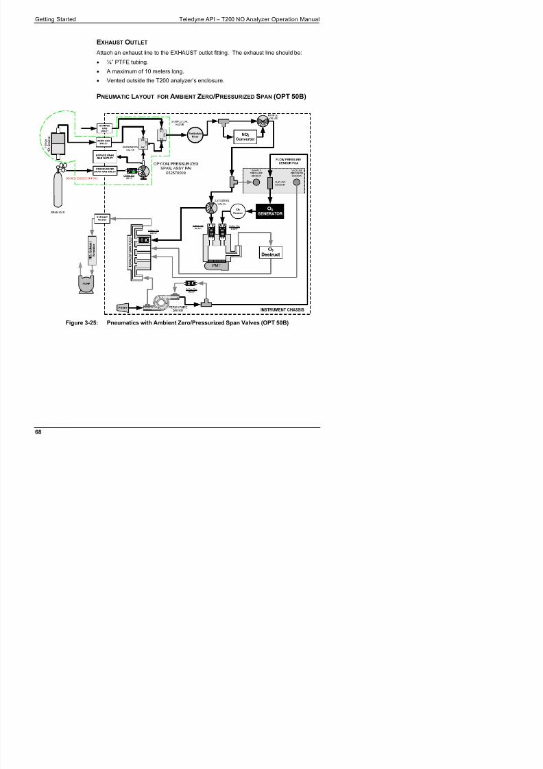
8/9/2019 06858D_T200
http://slidepdf.com/reader/full/06858dt200 70/476
¼” PTFE tubing.
A maximum of 10 meters long. Vented outside the T200 analyzer’s enclosure.
PNEUMATIC LAYOUT FOR AMBIENT ZERO /PRESSURIZED SPAN (OPT 50B)
Figure 3-25: Pneumatics with Ambient Zero/Pressurized Span Valves (OPT 50B)
Teledyne API – T200 NO Analyzer Operation Manual Getting Started
Table 3-10: Valve Operating States OPT 50B installed
MODE VALVE CONDITIONVALVE PORT
STATUS

8/9/2019 06858D_T200
http://slidepdf.com/reader/full/06858dt200 71/476
STATUS
Sample/Cal Open to SAMPLE inlet NO COM
Zero/Span Open to ZERO AIR inlet NO COM
Span Shutoff ClosedSAMPLE
Zero Air Shutoff Closed
Sample/Cal Open to ZERO/SPAN Valve NC COM
Zero/Span Open to ZERO AIR inlet NO COM
Span Shutoff OPENZERO CAL
Zero Air Shutoff 1 Closed
Sample/Cal Open to ZERO/SPAN Valve NC COM
Zero/Span Open to SPAN inlet NC COM
Span Shutoff ClosedSPAN CAL
Zero Air Shutoff OPEN
3.3.2.5. ZERO SCRUBBER AND INTERNAL SPAN SOURCE (IZS) (OPT 50G)
The T200 nitrogen oxides analyzer can also be equipped with an internal NO2 span gas
generator and calibration valve option. This option package is intended for applications
where there is a need for frequent automated calibration checks without access to an
external source of span gas.
This valve package includes:
A 2-stage external scrubber for producing zero air.
50% Purafil Chemisorbant®
(for conversion of NO NO2).
50% charcoal (for removal of the NO2).
A heated enclosure for a NO2 permeation tube.
This option package DOES NOT contain an actual permeation tube. SeeTable 1-1 for information on specifying the correct permeation tube for eachapplication.
A special desorber that removes all HNO3 from the calibration gas stream.
One additional gas inlet port (ZERO AIR).
One additional gas outlet port (FROM DRYER).
Two internal valves for switching between the sample gas inlet and the output of thezero/span subsystem.
Getting Started Teledyne API – T200 NO Analyzer Operation Manual

8/9/2019 06858D_T200
http://slidepdf.com/reader/full/06858dt200 72/476
Figure 3-26: Rear Panel Layout with Internal Span Source (IZS) OPT 50G
INTERNAL SPAN GAS GENERATION
The primary component of the internal span option is a permeation tube containing
liquid NO2. As zero air is passed over a permeable membrane on the end of the tube,
molecules of NO2 slowly pass through the membrane mixing with the zero air.
The resulting concentration of the NO2 span gas is determined by three factors:
Size of the membrane: The larger the area of the membrane, the more permeationoccurs.
Temperature of the NO2: Increasing the temperature of the permeation tubeincreases the pressure inside the tube and therefore increases the rate ofpermeation.
Flow rate of the zero air: If the previous two variables are constant, the permeationrate of the NO2 into the zero air stream will be constant. Therefore, a lower flowrate of zero air produces higher concentrations of NO2.
In the Model T200 the permeation tube enclosure is heated to a constant 50° C (10°
above the maximum operating temperature of the instrument) in order to keep the
permeation rate constant. A thermistor measures the actual temperature and reports it to
h CPU f l f db k
Teledyne API – T200 NO Analyzer Operation Manual Getting Started
NITRIC ACID AND THE CHEMISTRY OF NO2 PERMEATION TUBES
The reaction of H2O with NO2 to form HNO3 (nitric acid) takes place whenever water
and NO2 are present in the same gas mixture. In the T200 this is mitigated as much as

8/9/2019 06858D_T200
http://slidepdf.com/reader/full/06858dt200 73/476
2 p g g
possible by passing the air supply for the span gas generator through a special dryer,
however the permeable membrane of the NO2 tube will still allow H2O from the ambient
environment to slowly collect in the tube at increasingly higher concentrations. Over
time this results in the presence of HNO3 in the permeation tube which is exuded into
the T200’s pneumatics along with NO2.
HNO3 is a liquid at room temperature, so once the HNO3 is released by the permeation
tube it condenses and collects along the T200’s wetted surfaces, While liquid HNO 3
does not directly effect the quality of NOx measurements of the Model T200, it does
give off small amounts of gaseous HNO3 which is converted into NO by the T200’s NOx NO converter resulting in an artificially high NO2 concentration by 8% to 12%. This
is particularly bothersome when T200 is attempting to measure a zero point, such as
during calibration, since the NO2 concentration will only reach a true zero point once the
majority of the HNO3 coating the wetted surfaces has reverted to NO2 and this can take a
very long time.
The T200 includes a special HNO3 desorbed which eliminates any HNO3 given off by
the permeation tube before it can be converted into NO by the analyzer’s converter.
PNEUMATIC LAYOUT FOR ZERO SCRUBBER AND IZS (OPT 50G)
SAMPLEPRESSURE
SENSOR
VACUUMPRESSURE
SENSOR
O3FLOWSENSOR
PMT
E X H A U
S T M
A N I F O L D
NO/NOXVALVE
AUTOZERO
VALVE
SAMPLE/CAL
VALVE
ZERO/SPAN
VALVE
2 - S t a g e
N O X S
c r u b b e r OPTION,IZSW/VALVES,
DESORBERP/N
042310200
Getting Started Teledyne API – T200 NO Analyzer Operation Manual
Table 3-11: Internal Span Gas Generator Valve Operating States OPT 50G
MODE VALVE CONDITIONVALVE PORT
STATUS

8/9/2019 06858D_T200
http://slidepdf.com/reader/full/06858dt200 74/476
Sample/Cal Open to SAMPLE inlet NO COMSAMPLE
Zero/Span Open to ZERO AIR inlet NO COM
Sample/Cal Open to ZERO/SPAN Valve NC COMZERO CAL
Zero/Span Open to ZERO AIR inlet NO COM
Sample/Cal Open to ZERO/SPAN Valve NC COMSPAN CAL
Zero/Span Open to SPAN inlet NC COM
3.3.2.6. GAS CONDITIONER OPTIONS
AMMONIA REMOVAL SAMPLE CONDITIONER (OPT 86A)
The T200 includes a Nafion® permeation gas exchange tube to remove H2O a from the
ozone generator supply gas stream to a dew point of about -20° C (~600 ppm H2O) and
effectively remove concentrations of ammonia (NH3) up to about 1 ppm.
An additional Sample Conditioner can be added to the T200’s sample gas stream.
SAMPLE
PRESSURE
SENSOR
VACUUM
PRESSURE
SENSOR
O3 FLOW
SENSOR
FLOW PRESSURESENSOR PCA
PMT
E X H A U S T M A N I F O L D
NO/NOX
VALVE
AUTOZEROVALVE
O3
Destruct
O3
GENERATORO3
Cleanser
NO2
Converter
Exhaust
Outlet
NO
NC
NO
NC
SAMPLE
GAS
INLET
PERMAPUREDRYER
PUMP
N
O X
E x h a u s t
S c r u b b e r
Orifice Dia.
0.004"
Orifice Dia.
0.010"
Orifice Dia.
0.010"
Orifice Dia.
0.004"
Orifice Dia.
0.004"
OPTION, SAMPLECONDITIONER, P/ N 05994
COM
COM
Teledyne API – T200 NO Analyzer Operation Manual Getting Started
3.4. STARTUP, FUNCTIONAL CHECKS, AND INITIALCALIBRATION

8/9/2019 06858D_T200
http://slidepdf.com/reader/full/06858dt200 75/476
CALIBRATION
If you are unfamiliar with the T200 principles of operation, we recommend that you read
Section 13. For information on navigating the analyzer’s software menus, see the menu
trees described in Appendix A.
3.4.1. START UPAfter the electrical and pneumatic connections are made, an initial functional check is in
order. Turn on the instrument. The pump and exhaust fan should start immediately. Thedisplay will show a splash screen and other information during the initialization process
while the CPU loads the operating system, the firmware and the configuration data.
The analyzer should automatically switch to Sample Mode after completing the boot-up
sequence and start monitoring the gas. However, there is an approximately one hour
warm-up period before reliable gas measurements can be taken. During the warm-up
period, the front panel display may show messages in the parameters (Param) field.
CAUTION!If the presence of ozone is detected at any time, power down the instrument
and contact Teledyne API Customer Service as soon as possible:
800-324-5190 or email: [email protected]
Getting Started Teledyne API – T200 NO Analyzer Operation Manual
3.4.2. WARNING MESSAGESBecause internal temperatures and other conditions may be outside the specified limits

8/9/2019 06858D_T200
http://slidepdf.com/reader/full/06858dt200 76/476
during the analyzer’s warm-up period, the software will suppress most warning
conditions for 30 minutes after power up. If warning messages persist after the 30
minutes warm up period is over, investigate their cause using the troubleshooting
guidelines in Section 12.1.
To view and clear warning messages, press:
Table 3-12 lists brief descriptions of the warning messages that may occur during
start up.
Teledyne API – T200 NO Analyzer Operation Manual Getting Started
Table 3-12: Possible Warning Messages at Start-Up
MESSAGE MEANING
SYSTEM RESET1The computer has rebooted.

8/9/2019 06858D_T200
http://slidepdf.com/reader/full/06858dt200 77/476
ANALOG CAL WARNING The A/D or at least one D/A channel have not been calibrated.
BOX TEMP WARNING The temperature inside the T200 chassis is outside the specified limits.
CANNOT DYN SPAN2Contact closure span calibration failed while DYN_SPAN was set to ON.
CANNOT DYN ZERO3Contact closure zero calibration failed while DYN_ZERO was set to ON.
CONFIG INITIALIZED Configuration storage was reset to factory configuration or erased.
DATA INITIALIZED DAS data storage was erased before the last power up occurred.
OZONE FLOW WARNING Ozone gas flow is too high or too low for accurate NOx, NO and NO2 readings.
OZONE GEN OFF 4
Ozone generator is off.
This is the only warning message that automatically clears itself.
It clears itself when the ozone generator is turned on.
Upon power up the Ozone generator will remain off for 30 minutes. This allows the perma-pure dryer to reach its working dew point.
RCELL PRESS WARN Reaction cell pressure is too high or too low for accurate NOx, NO and NO2 readings.
RCELL TEMP WARNING Reaction cell temperature is too high or too low for accurate NOx, NO and NO2 readings.
IZS TEMP WARNING 5 IZS temperature is too high or too low for efficient O3 production.
CONV TEMP WARNING NO2 to NO Converter temperature too high or too low to efficiently convert NO2 to NO.
PMT TEMP WARNING PMT temperature outside of warning limits specified by PMT_SET variable.
AZERO WARN [XXXX] MV
AutoZero reading too high. The value shown in message indicates auto-zero reading attime warning was displayed.
HVPS WARNING High voltage power supply output is too high or too low for proper operation of the PMT.
REAR BOARD NOT DET CPU unable to communicate with motherboard..
RELAY BOARD WARN CPU is unable to communicate with the relay PCA.
SAMPLE FLOW WARN The flow rate of the sample gas is outside the specified limits.
1 Clears 45 minutes after power up.
2 Clears the next time successful zero calibration is performed.
3 Clears the next time successful span calibration is performed.
4 Clears 30 minutes after power up.
5 Only Appears if the IZS option is installed.
Getting Started Teledyne API – T200 NO Analyzer Operation Manual
3.4.3. FUNCTIONAL CHECKSAfter the analyzer’s components have warmed up for at least 60 minutes, verify that the

8/9/2019 06858D_T200
http://slidepdf.com/reader/full/06858dt200 78/476
y p p , y
software properly supports any hardware options that are installed.
For information on navigating through the analyzer’s software menus, see the menu
trees described in Appendix A.1.
Check to ensure that the analyzer is functioning within allowable operating parameters.
Appendix C includes a list of test functions viewable from the analyzer’s front panelas well as their expected values.
These functions are also useful tools for diagnosing problems with your analyzer.
The enclosed Final Test and Validation Data sheet (P/N 04409) lists these valuesbefore the instrument left the factory.
To view the current values of these parameters press the following button sequence on
the analyzer’s front panel. Remember until the unit has completed its warm up these
parameters may not have stabilized.
Teledyne API – T200 NO Analyzer Operation Manual Getting Started
3.4.4. INITIAL CALIBRATIONTo perform the following calibration you must have sources for zero air and calibration
(span) gas available for input into the inlet/outlet fittings on the back of the analyzer (see
S ti 3 3 2 1)

8/9/2019 06858D_T200
http://slidepdf.com/reader/full/06858dt200 79/476
Section 3.3.2.1).
Note A start-up period of 4-5 hours is recommended prior to performing acalibration on the analyzer.
The method for performing an initial calibration for the T200 nitrogen oxides analyzer
differs slightly depending on the whether or not any of the available internal zero air or
valve options are installed.
See Section 3.4.4.2 for instructions for initial calibration of the T200 analyzers intheir base configuration.
See Section 9.3 for instructions for initial calibration of T200 analyzers possessingan optional Internal Span Gas Generator (OPT 51A).
See Section 9.4 for information regarding setup and calibration of T200 analyzerswith Z/S Valve options.
If you are using the T200 analyzer for EPA monitoring, only the calibration methoddescribed in Section 10 should be used.
3.4.4.1. INTERFERENTS FOR NOX, NO AND NO2 MEASUREMENTSThe chemiluminescence method for detecting NOX is subject to interference from a
number of sources including water vapor (H2O), ammonia (NH3), sulfur dioxide (SO2)
and carbon dioxide (CO2) but the T200 has been designed to reject most of these
interferences.
Ammonia is the most common interferent, which is converted to NO in theanalyzer’s NO2 converter and creates a NOX signal artifact.
If the T200 is installed in an environment with high ammonia, steps should betaken to remove the interferent from the sample gas before it enters the reactioncell.
Teledyne API offers a sample gas conditioning option to remove ammonia andwater vapor (Section 3.3.2.6).
Carbon dioxide (CO2) diminishes the NOX signal when present in highconcentrations.
If the analyzer is used in an application with excess CO2, contact Teledyne API's Customer Service Department (see Section 12.10) for possible solutions.
Excess water vapor can be removed with one of the dryer options described in
Getting Started Teledyne API – T200 NO Analyzer Operation Manual
3.4.4.2. INITIAL CALIBRATION PROCEDURE FOR T200 ANALYZERS WITHOUT OPTIONS
The following procedure assumes that:
The instrument DOES NOT have any of the available calibration valve or gas inletoptions installed;

8/9/2019 06858D_T200
http://slidepdf.com/reader/full/06858dt200 80/476
options installed;
Cal gas will be supplied through the SAMPLE gas inlet on the back of the analyzerand;
The pneumatic setup matches that described in Section 3.3.2.
VERIFYING THE REPORTING RANGE SETTINGS
While it is possible to perform the following procedure with any range setting we
recommend that you perform this initial checkout using following reporting range
settings:
Unit of Measure: PPB
Reporting Range: 500 ppb
Mode Setting: SNGL
While these are the default setting for the T200 analyzer, it is recommended that you
verify them before proceeding with the calibration procedure, by pressing the following
menu button sequence:

8/9/2019 06858D_T200
http://slidepdf.com/reader/full/06858dt200 81/476
Getting Started Teledyne API – T200 NO Analyzer Operation Manual
VERIFYING THE EXPECTED NOX AND NO SPAN GAS CONCENTRATION
IMPORTANT IMPACT ON READINGS OR DATA Verify the PRECISE Concentration Value of the SPAN gases

8/9/2019 06858D_T200
http://slidepdf.com/reader/full/06858dt200 82/476
Verify the PRECISE Concentration Value of the SPAN gasesindependently.
If you supply NO gas to the analyzer, the values for expected NO andNOx MUST be identical.
The NOx and NO span concentration values automatically defaults to 400.0 PPB and it
is recommended that calibration gases of that concentration be used for the initial
calibration of the unit.
To verify that the analyzer span setting is set for 400 PPB, press:
Teledyne API – T200 NO Analyzer Operation Manual Getting Started
INITIAL ZERO /SPAN CALIBRATION PROCEDURE
To perform an initial Calibration of the T200 nitrogen oxides analyzer, press:

8/9/2019 06858D_T200
http://slidepdf.com/reader/full/06858dt200 83/476
Getting Started Teledyne API – T200 NO Analyzer Operation Manual

8/9/2019 06858D_T200
http://slidepdf.com/reader/full/06858dt200 84/476
This page intentionally left blank.

8/9/2019 06858D_T200
http://slidepdf.com/reader/full/06858dt200 85/476

8/9/2019 06858D_T200
http://slidepdf.com/reader/full/06858dt200 86/476

8/9/2019 06858D_T200
http://slidepdf.com/reader/full/06858dt200 87/476
4. OVERVIEW OF OPERATING MODES
To assist in navigating the analyzer’s software, a series of menu trees is available for
reference in Appendix A of this manual.
Note Some control buttons on the touch screen do not appear if they are notapplicable to the menu that you’re in, the task that you are performing, thecommand you are attempting to send, or to incorrect settings input by theuser. For example, the ENTR button may disappear if you input a settingthat is invalid or out of the allowable range for that parameter, such astrying to set the 24-hour clock to 25:00:00. Once you adjust the setting to
an allowable value, the ENTR button will re-appear.
The T200 analyzer software has a variety of operating modes. The most common mode
that the analyzer will be operating in is the SAMPLE mode. In this mode, a continuous
read-out of the NOx concentrations can be viewed on the front panel and output as an
analog voltage from rear panel terminals.
The second most important operating mode is SETUP mode. This mode is used for
configuring the various sub systems of the analyzer such as for the DAS system, the
reporting ranges, or the serial (RS-232 / RS-485 / Ethernet) communication channels.The SETUP mode is also used for performing various diagnostic tests during
troubleshooting.
Overview of Operating Modes Teledyne API – T200 NO Analyzer Operation Manual
The mode field of the front panel display indicates to the user which operating mode the
unit is currently running.
In addition to SAMPLE and SETUP, other modes the analyzer can be operated in are
described in Table 7-1 below.

8/9/2019 06858D_T200
http://slidepdf.com/reader/full/06858dt200 88/476
Table 4-1: Analyzer Operating Modes
MODE EXPLANATION
DIAG One of the analyzer’s diagnostic modes is active.
LO CAL A Unit is performing LOW SPAN (midpoint) calibration initiated automatically by the analyzer’s AUTOCAL feature
LO CAL R Unit is performing LOW SPAN (midpoint) calibration initiated remotely through the COM ports ordigital control inputs.
M-P CAL This is the basic calibration mode of the instrument and is activated by pressing the CAL button.
SAMPLE Sampling normally, flashing text indicates adaptive filter is on.
SAMPLE A Indicates that unit is in SAMPLE mode and AUTOCAL feature is activated.
SETUP X.#2 SETUP mode is being used to configure the analyzer. The gas measurement will continue duringsetup.
SPAN CAL A1 Unit is performing SPAN calibration initiated automatically by the analyzer’s AUTOCAL feature
SPAN CAL M1 Unit is performing SPAN calibration initiated manually by the user.
SPAN CAL R1 Unit is performing SPAN calibration initiated remotely through the COM ports or digital controlinputs.
ZERO CAL A1 Unit is performing ZERO calibration procedure initiated automatically by the AUTOCAL feature
ZERO CAL M1Unit is performing ZERO calibration procedure initiated manually by the user.
ZERO CAL R1 Unit is performing ZERO calibration procedure initiated remotely through the COM ports or digitalcontrol inputs.
1 Only Appears on units with Z/S valve or IZS options.
2 The revision of the analyzer firmware is displayed following the word SETUP, e.g., SETUP G.3.
4.1. SAMPLE MODEThis is the analyzer’s standard operating mode. In this mode, the instrument is a
calculating NOx, NO and NO2 concentrations. These values are displayed in the CONC
field of the analyzer's front panel display. While the instrument is in SAMPLE mode,
this field provides a readout of all the gas concentrations being measured by the T200:
NOx, NO and NO2.
When the analyzer is in sample mode the PARAM field will display warning messagesand test functions that give the user information about the operational status of the
analyzer.
Teledyne API – T200 NO Analyzer Operation Manual Overview of Operating Modes
Table 4-2: Test Functions Defined
DISPLAY PARAMETER UNITS DESCRIPTION
RANGE
The Full Scale limit at which the reporting range of the analyzer’s ANALOGOUTPUTS is currently set.
THIS IS NOT the Physical Range of the instrument. See Section 5.4.1 for
more information

8/9/2019 06858D_T200
http://slidepdf.com/reader/full/06858dt200 89/476
more information.
RANGE1RANGE2
If AUTO Range mode has been selected, two RANGE functions willappear, one for each range:
RANGE1: The range setting for all analog outputs.
RANGE2: The HIGH range setting for all analog outputs.
RANGE1RANGE2RANGE3
RANGE
PPB,PPM,UGM
&MGM If the IND Range mode has been selected, three RANGE functions will
appear, one for each range:
RANGE1: NOx concentration output un A1.
RANGE2: NO concentration output un A2.
RANGE2: NO2 concentration output un A3.
NOX STB STABILITY PPB
The standard deviation of concentration readings of the selected gas.
Data points are recorded every ten seconds. The calculation uses thelast 25 data points.
SAMP FLW SAMPFLOW CC/M Gas flow rate of the sample gas into the reaction cell.
OZONE FL OZONEFLOW CC/M Gas flow rate of O3 gas into the reaction cell.
PMT PMT MV The raw signal output of the PMT.
NORM PMT NORMPMT MVThe signal output of the PMT after is has been normalized for temperature,pressure, auto-zero offset, but not range.
AZERO AUTOZERO MVThe PMT signal with zero NOX, which is usually slightly different from 0 V.This offset is subtracted from the PMT signal and adjusts for variations inthe zero signal.
HVPS HVPS V The output power level of the high voltage power supply.
RCELL TEMP RCELLTEMP C The temperature of the gas inside the reaction cell temperature.
BOX TEMP BOXTEMP C The temperature inside the analyzer chassis.
PMT TEMP PMTTEMP C The temperature of the PMT .
IZS TEMP1IZSTEMP C The temperature of the internal span gas generator's permeation tube.
MOLY TEMP CONVTEMP C The temperature of the analyzer's NO2 NO converter.
RCEL RCELLPRESS IN-HG-AThe current pressure of the sample gas in the reaction cell as measured atthe vacuum manifold.
SAMP SAMPPRESS IN-HG-AThe current pressure of the sample gas as it enters the reaction cell,measured between the NO/NOx and Auto-Zero valves.
NOX SLOPE NOXSLOPE The slope calculated during the most recent NOx zero/span calibration.
NOX OFFS NOXOFFSET MV The offset calculated during the most recent NOx zero/span calibration.
NO SLOPE NOSLOPE The slope calculated during the most recent NO zero/span calibration.
NO OFFS NOOFFSET MV The offset calculated during the most recent NO zero/span calibration.
TEST TESTCHAN MV
Displays the signal level of the Test Function that is currently beingproduced by the Analog Output Channel A4.
TIME CLOCKTIME HH:MM:SSThe current time. This is used to create a time stamp on DAS readings,and by the AutoCal feature to trigger calibration events.
Overview of Operating Modes Teledyne API – T200 NO Analyzer Operation Manual
To view these TEST functions, press,

8/9/2019 06858D_T200
http://slidepdf.com/reader/full/06858dt200 90/476
Figure 4-2: Viewing T200 Test Functions
IMPORTANT IMPACT ON READINGS OR DATA A value of “XXXX” displayed for any of the TEST functions indicates anout-of-range reading or the analyzer’s inability to calculate it. Allpressure measurements are represented in terms of absolute pressure.Absolute, atmospheric pressure is 29.92 in-Hg-A at sea level. Itdecreases about 1 in-Hg per 300 m gain in altitude. A variety of factorssuch as air conditioning and passing storms can cause changes in theabsolute atmospheric pressure.
Teledyne API – T200 NO Analyzer Operation Manual Overview of Operating Modes
4.1.2. WARNING MESSAGESThe most common and serious instrument failures will activate Warning Messages that
are displayed on the analyzer’s Front Panel. They are listed on Table 4-3 as follows:

8/9/2019 06858D_T200
http://slidepdf.com/reader/full/06858dt200 91/476
Table 4-3: Warning Messages Defined
MESSAGE MEANINGANALOG CAL WARNING The A/D or at least one D/A channel has not been calibrated.
AZERO WARN Auto-zero reading above limit specified by AZERO_LIMIT variable. Value shownin message indicates auto-zero reading at time warning was displayed.
BOX TEMP WARNING The temperature inside the T200 chassis is outside the specified limits.
CANNOT DYN SPAN Contact closure span calibration failed while DYN_SPAN was set to ON.CANNOT DYN ZERO Contact closure zero calibration failed while DYN_ZERO was set to ON.
CONFIG INITIALIZED Configuration storage was reset to factory configuration or erased.
CONV TEMP WARNING NO2 NO converter temperature outside of warning limits specified byCONV_SET variable.
DATA INITIALIZED DAS data storage was erased before the last power up occurred.
HVPS WARNING High voltage power supply output outside of warning limits specified byHVPS_SET variable.
IZS TEMP WARNING1
IZS temperature outside of warning limits specified by IZS_SET variable.OZONE FLOW WARNING Ozone flow outside of warning limits specified by OFLOW_SET variable.
OZONE GEN OFF Ozone generator is off. This warning message clears itself when the ozonegenerator is turned on.
PMT TEMP WARNING PMT temperature outside of warning limits specified by PMT_SET variable.
RCELL PRESS WARN Reaction cell pressure outside of warning limits specified byRCELL_PRESS_SET variable.
RCELL TEMP WARNING Reaction cell temperature outside of warning limits specified by RCELL_SET variable.
REAR BOARD NOT DET Motherboard was not detected during power up.
RELAY BOARD WARN CPU is unable to communicate with the relay PCA.
SAMPLE FLOW WARN The flow rate of the sample gas is outside the specified limits.
SYSTEM RESET The computer has rebooted.
1 Only Appears if the Internal Span Gas Generator option is installed.
Overview of Operating Modes Teledyne API – T200 NO Analyzer Operation Manual
4.2. CALIBRATION MODEPressing the CAL button, switches the analyzer into calibration mode. In this mode the
user can, in conjunction with introducing zero or span gases of known concentrationsinto the analyzer cause it to adjust and recalculate the slope (gain) and offset of the its

8/9/2019 06858D_T200
http://slidepdf.com/reader/full/06858dt200 92/476
user can, in conjunction with introducing zero or span gases of known concentrationsinto the analyzer, cause it to adjust and recalculate the slope (gain) and offset of the its
measurement range. This mode is also used to check the current calibration status of the
instrument.
If the instrument includes one of the available zero/span valve options, the SAMPLE
mode display will also include CALZ and CALS buttons. Pressing either of these
buttons also puts the instrument into calibration mode.
The CALZ button is used to initiate a calibration of the analyzer’s zero point using
internally generated zero air.
The CALS button is used to calibrate the span point of the analyzer’s currentreporting range using span gas.
Note It is recommended that this span calibration be performed at 80% of fullscale of the analyzer’s currently selected reporting range.
EXAMPLES:If the reporting range is set for 0 to 500 ppb, an appropriate span pointwould be 400 ppb.
If the of the reporting range is set for 0 to 1000 ppb, an appropriate spanpoint would be 800 ppb.
Due to the critical importance and complexity, calibration operations are described in
detail in other sections of the manual:
Section 9 details setting up and performing standard calibration operations orchecks.
Section 10 details setting up and performing EPA protocol calibrations.
For information on using the automatic calibrations feature (ACAL) in conjunction with
the one of the calibration valve options, see Sections 9.4.3 and 9.5.
IMPORTANT IMPACT ON READINGS OR DATA To avoid inadvertent adjustments to critical settings, activate calibrationsecurity by enabling password protection in the SETUP – PASS menu
Teledyne API – T200 NO Analyzer Operation Manual Overview of Operating Modes
4.3. SETUP MODEThe SETUP Mode contains a variety of choices that are used to configure the analyzer’s
hardware and software features, perform diagnostic procedures, gather information on
the instruments performance and configure or access data from the internal data
acquisition system (DAS). For a visual representation of the software menu trees, refer

8/9/2019 06858D_T200
http://slidepdf.com/reader/full/06858dt200 93/476
q y ( ) p ,to Appendix A.
SETUP Mode is divided between Primary and Secondary Setup menus and can be
protected through password security.
4.3.1. PASSWORD SECURITYSETUP Mode can be protected by password security through the SETUP>PASS menu
(Section 5.5) to prevent unauthorized or inadvertent configuration adjustments.
4.3.2. PRIMARY SETUP MENUThe areas accessed and configured under the primary SETUP Mode menu are shown in
Table 4-4.
Table 4-4: Primary Setup Mode Features and Functions
MODE OR FEATURECONTROLBUTTONLABEL
DESCRIPTIONMANUALSECTION
Analyzer Configuration CFG Lists button hardware and software configuration information. 5.1
Auto Cal Feature ACAL
Used to set up and operate the AutoCal feature.
Only appears if the analyzer has one of the calibration valveoptions installed.
5.2, 9.5
Internal Data Acquisition
(DAS)
DAS Used to set up the DAS system and view recorded data. 7
Analog Output ReportingRange Configuration
RNGEUsed to configure the output signals generated by theinstruments analog outputs.
5.4
Calibration Password Security PASS Turns the calibration password feature ON/OFF. 5.5
Internal Clock Configuration CLK Used to set or adjust the instrument’s internal clock. 5.6
Secondary SETUP Mode
(Advanced SETUP features)MORE This button accesses the instruments secondary setup menu.
SeeTable 4-5
Overview of Operating Modes Teledyne API – T200 NO Analyzer Operation Manual
4.3.3. SECONDARY SETUP MENU (SETUP MORE)The areas accessed and configured under the secondary SETUP Mode menu are shown
in Table 4-5.
Table 4-5: Secondary Setup Mode Features and Functions

8/9/2019 06858D_T200
http://slidepdf.com/reader/full/06858dt200 94/476
y p
MODE OR FEATURECONTROLBUTTONLABEL
DESCRIPTIONMANUALSECTION
External CommunicationChannel Configuration
COMMUsed to set up and operate the analyzer’s various external I/Ochannels including RS-232; RS-485, modem communicationand/or Ethernet access.
8
System Status Variables VARS
Used to view various variables related to the instrumentscurrent operational status.
Changes made to any variable are not acknowledged andrecorded in the instrument’s memory until the ENTR buttonis pressed.
Pressing the EXIT button ignores the new setting.
If the EXIT button is pressed before the ENTR button, theanalyzer will beep alerting the user that the newly enteredvalue has been lost.
5.8
System Diagnostic Features
and Analog Output Configuration DIAG
Used to access a variety of functions that are used to configure,test or diagnose problems with a variety of the analyzer’s basic
systems.Most notably, the menus used to configure the output signalsgenerated by the instruments’ analog outputs are located here.
5.9, 5.9.2
IMPORTANT IMPACT ON READINGS OR DATA Any changes made to a variable during the SETUP procedures are notacknowledged by the instrument until the ENTR button is pressed. If theEXIT button is pressed before the ENTR button, the analyzer will make anaudible signal before exiting the menu, alerting the user that the newlyentered value had not been accepted.

8/9/2019 06858D_T200
http://slidepdf.com/reader/full/06858dt200 95/476
5. SETUP MENU
The SETUP Mode menu is used to set instrument parameters for performing
configuration, calibration, reporting and diagnostics operations according to user needs.
5.1. SETUP CFG: CONFIGURATION INFORMATIONPressing the CFG button displays the instrument configuration information. This display
lists the analyzer model, serial number, firmware revision, software library revision,
CPU type and other information. Use this information to identify the software and
hardware when contacting customer service. Special instrument or software features or
installed options may also be listed here.
Setup Menu Teledyne API – T200 NO Analyzer Operation Manual
5.2. SETUP ACAL: AUTOMATIC CALIBRATION OPTIONThe menu button for this option appears only when the instrument has the zero span
and/or IZS options. See Section 9.5 for details.
5 3 SETUP DAS: INTERNAL DATA ACQUISITION SYSTEM

8/9/2019 06858D_T200
http://slidepdf.com/reader/full/06858dt200 96/476
5.3. SETUP DAS: INTERNAL DATA ACQUISITION SYSTEMUse the SETUP>DAS menu to capture and record data. Refer to Section 7 for
configuration and operation details.
5.4. SETUP RNGE: ANALOG OUTPUT REPORTING RANGECONFIGURATION
Use the SETUP>RNGE menu to configure output reporting ranges, including scaled
reporting ranges to handle data resolution challenges. This section describes
configuration for Single, Dual, and Auto Range modes.
5.4.1. T200 PHYSICAL RANGESThe T200 NOx analyzer measures NOx, NO and NO2 concentrations from 2 to 20,000
ppb.Electronically the T200 analyzer converts the 0-5 volt analog signal output by the PMT
into a digital signal with 4096 counts of resolution. Since its measurement range is 0
ppb to 20,000 ppb, this only allows about 3 ppb per count. While this might be
acceptable for high concentration measurements made in parts per million units (ppm), it
is not good enough for lower level NOx measurements. To overcome this limitation the
T200 is designed with two physical measurement ranges:
A LOW range that measures concentration from 0 ppb to 2,000 ppb with a
resolution of 0.27 ppb per count.
A HIGH range that measures the full 20,000 ppb range of the analyzer.
The analyzer’s CPU chooses the appropriate range based on how the user sets up the
reporting ranges for the instruments analog outputs when an analog range is selected
with a lower limit between 0 and 2000 ppb the analyzer will utilize its low physical
range. When an analog range is in use that has a reporting range with an upper limit set
between 2001 and 20,000 ppb the instrument will operate in its high physical range.
Once both ranges have been using the same span gas values the analyzer’s front panel
will accurately report concentrations between 0 and 20,000 ppb, seamlessly switching
between the low and high physical ranges regardless of the selected analog reporting
range
Teledyne API – T200 NO Analyzer Operation Manual Setup Menu
The T200 solves this problem by allowing the user to select a reporting range for the
analog outputs that only includes that portion of the physical range that covers the
specific application. This increases the reliability and accuracy of the analyzer by
avoiding additional gain-amplification circuitry.
Note Only the reporting range of the analog outputs is scaled.

8/9/2019 06858D_T200
http://slidepdf.com/reader/full/06858dt200 97/476
Note Only the reporting range of the analog outputs is scaled.
Both the DAS values stored in the CPU’s memory and the concentrationvalues reported on the front panel are unaffected by the settings chosenfor the reporting range(s) of the instrument.
5.4.2.1. ANALOG OUTPUT RANGES FOR NOX, NO AND NO2 CONCENTRATIONThe analyzer has three active analog output signals related to NO x, NO and NO2
concentration, accessible through a connector on the rear panel.
NO2 Concentration
ANALOG OUT
A1 A2 A3 A4 + - + - + - + -
Test Channelor O2 concentration(if optional O2 sensor
is installed)
NO Concentration NOx Concentration
Figure 5-1: Analog Output Connector Pin Out
The A1, A2 and A3 channels output a signal that is proportional to the NO x, NO and
NO2 concentrations of the sample gas, respectively. The T200 can be set so that these
outputs operate in one of the three following modes: single range mode, independent
range mode, or automatic range mode (Section 5.4.3).
Additionally, the signal levels of outputs A1, A2 and A3 outputs can be: Configured full scale outputs of: 0 - 0.1 VDC; 0 – 1 VDC; 0 – 5 VDC or; 0 – 10 VDC.
Equipped with optional 0-20 mADC current loop drivers (see Section 3.3.1.4 ) andconfigured for any current output within that range analog output (e.g. 0-20 mA, 2-
Setup Menu Teledyne API – T200 NO Analyzer Operation Manual
A2 OUTPUT: NO Output Signal = 0 – 10 VDC representing 0-500 ppb concentration
values.
A3 OUTPUT: NO2 Output Signal = 0 – 5 VDC representing 0-500 ppb concentration
values.
The user may also add a signal offset independently to each output (see Section 5.9.3.9)to match the electronic input requirements of the recorder or data logger to which the

8/9/2019 06858D_T200
http://slidepdf.com/reader/full/06858dt200 98/476
to match the electronic input requirements of the recorder or data logger to which the
output is connected.
IMPORTANT IMPACT ON READINGS OR DATA The instrument does not remember upper range limits settings associatedwith the individual modes. Changes made to the range limits (e.g. 400 ppb
600 ppb) when in one particular mode will alter the range limit settingsfor the other modes.
When switching between reporting range modes, ALWAYS check andreset the upper range limits for the new mode selection..
5.4.2.2. ANALOG OUTPUT REPORTING RANGE DEFAULT SETTINGS
The default setting for these the reporting ranges of the analog output channels A1, A2 and A3 are:
SNGL mode
0 to 500.0 ppb
0 to 5 VDC
5.4.3. SETUP RNGE MODESingle range mode (SNGL) reports all three of the NOx gas concentrations using the
same reporting range span (see Section 5.4.3.1).
Independent range mode (IND) allows the NOx, NO and NO2 analog outputs to be set
with different reporting range spans (see Section 5.4.3.2).
Automatic range mode (AUTO) allows the analyzer to automatically switch the
reporting range between two user upper span limits (designated LOW and HIGH) based
on the actual concentrations being measured for each (see Section 5.4.3.3). These are not
the same as the analyzer’s low and high physical ranges.
5.4.3.1. SETUP RNGE MODE SNGL: CONFIGURING THE T200 ANALYZER FOR SINGLERANGE MODE
Teledyne API – T200 NO Analyzer Operation Manual Setup Menu
Although all three NOx outputs share the same concentration reporting range, the
electronic signal ranges of the analog outputs may still be configured for different values
(e.g. 0-5 VDC, 0-10 VDC, etc; see Section 5.9.3.1).
To select SNGL range mode and to set the upper limit of the range, press:

8/9/2019 06858D_T200
http://slidepdf.com/reader/full/06858dt200 99/476
Setup Menu Teledyne API – T200 NO Analyzer Operation Manual
5.4.3.2. SETUP RNGE MODE IND: CONFIGURING THE T200 ANALYZER FORINDEPENDENT RANGE MODE
The independent range mode (IND) assigns the three NOx, NO and NO2 concentrations
to individual analog output channels. In IND range mode the RANGE test function
displayed on the front panel will then be replaced by three separate functions:
Table 5 1: IND Mode Analog Output Assignments

8/9/2019 06858D_T200
http://slidepdf.com/reader/full/06858dt200 100/476
Table 5-1: IND Mode Analog Output Assignments
TESTFUNCTION
CONCENTRATIONREPORTED
ANALOG OUTPUTCHANNEL
RANGE1 NOx A1
RANGE2 NO A2
RANGE3 NO2 A3
Each can be configured with a different reporting range upper limit and analog signal
span:
EXAMPLE:
NOx Concentration – RANGE1 Set for 0-800 ppb & output A1 set for 0-10 VDC
NO Concentration – RANGE2 Set for 0-200 ppb & output A2 set for 0-5 VDC
NO2 Concentration – RANGE3 Set for 0-400 ppb & output A3 set for 0-5 VDC
Setting analog range limits to different values does not affect the instrument’s
calibration.
Teledyne API – T200 NO Analyzer Operation Manual Setup Menu
To select the IND range mode, press the following buttons:
Concentration fielddi l ll
SAMPLE RANGE=500.0 PPM NOX= XXXX
<TST TST> CAL SETUP

8/9/2019 06858D_T200
http://slidepdf.com/reader/full/06858dt200 101/476
displays all gases.
SETUP X.X PRIMARY SETUP MENU
CFG DAS RNGE PASS CLK MORE EXIT
SETUP X.X RANGE MODE MENU
MODE SET UNIT DIL EXIT
SETUP X.X RANGE MODE:SNGL
SNGL IND AUTO ENTR EXIT
SETUP X.X RANGE MODE:IND
SNGL IND AUTO ENTR EXIT
SETUP X.X RANGE MODE MENU
MODE SET UNIT DIL EXIT
Setup Menu Teledyne API – T200 NO Analyzer Operation Manual
To set the upper range limit for each independent reporting range, press:

8/9/2019 06858D_T200
http://slidepdf.com/reader/full/06858dt200 102/476
.
Teledyne API – T200 NO Analyzer Operation Manual Setup Menu
5.4.3.3. SETUP RNGE MODE AUTO: CONFIGURING THE T200 ANALYZER FOR AUTORANGE MODE
In AUTO range mode, the analyzer automatically switches the reporting range
between two user-defined ranges (LOW and HIGH). The same low and high spansettings are applied equally to NO, NO2 and NOX readings.

8/9/2019 06858D_T200
http://slidepdf.com/reader/full/06858dt200 103/476
The unit will switch from LOW range to HIGH range when either the NO, or NOX concentration exceeds 98% of the low range span.
The unit will return from HIGH range back to LOW range once both the NO andNOX concentrations fall below 75% of the low range span.
IMPORTANT IMPACT ON READINGS OR DATA The LOW & HIGH ranges referred to here are NOT the same as the low &high physical ranges referred to in Section 5.4.1.
Also the RANGE test function displayed on the front panel will be replaced by two
separate functions:
RANGE1: The LOW range setting for all analog outputs.
RANGE2: The HIGH range setting for all analog outputs.
The LOW/HIGH range status is also reported through the external, digital status bits
(Section 3.3.1.4). To set individual ranges press the following menu sequence.
Setup Menu Teledyne API – T200 NO Analyzer Operation Manual

8/9/2019 06858D_T200
http://slidepdf.com/reader/full/06858dt200 104/476
Teledyne API – T200 NO Analyzer Operation Manual Setup Menu
5.4.3.4. SETUP RNGE UNIT: SETTING THE REPORTING RANGE UNITS OF MEASURE
The T200 can display and report concentrations in ppb, ppm, ug/m3, mg/m3 units.
Changing units affects all of the COMM port values, and all of the display values for all
reporting ranges. To change the units of measure press:

8/9/2019 06858D_T200
http://slidepdf.com/reader/full/06858dt200 105/476
IMPORTANT IMPACT ON READINGS OR DATA Concentrations displayed in mg/m3 and ug/m3 use 0C @ 760 mmHg forStandard Temperature and Pressure (STP).
Consult your local regulations for the STP used by your agency.(Example: US EPA uses 25C as the reference temperature).
Once the Units of Measurement have been changed from volumetric (ppb
or ppm) to mass units (ug/m3 or mg/m3) the analyzer MUST berecalibrated, as the “expected span values” previously in effect will nolonger be valid.
Simply entering new expected span values without running the entire
Setup Menu Teledyne API – T200 NO Analyzer Operation Manual
5.4.3.5. SETUP RNGE DIL: USING THE OPTIONAL DILUTION RATIO FEATURE
The dilution ratio feature is a software utility option designed for applications where the
sample gas is diluted before being analyzed by the T200. Typically this occurs in
continuous emission monitoring (CEM) applications where the quality of gas in a smoke
stack is being tested and the sampling method used to remove the gas from the stack
dilutes the gas. Once the degree of dilution is known, this feature allows the user to add
an appropriate scaling factor to the analyzer’s NO, NO2 and NOx concentration

8/9/2019 06858D_T200
http://slidepdf.com/reader/full/06858dt200 106/476
pp p g y
calculations so that the measurement range and concentration values displayed on the
instrument’s front panel display and reported via the instruments various outputs reflect
the undiluted values.
Using the Dilution Ratio option is a 4-step process:
1. Select the appropriate units of measure (see Section 5.4.3.4).
2. Select the reporting range mode and set the reporting range upper limit (seeSection 5.4.2).
Ensure that the upper span limit entered for the reporting range is the maximumexpected concentration of the UNDILUTED gas.
3. Set the dilution factor as a gain (e.g., a value of 20 means 20 parts diluent and 1part of sample gas):
Teledyne API – T200 NO Analyzer Operation Manual Setup Menu
EXAMPLE: If the reporting range limit is set for 100 ppm and the dilution ratio of
the sample gas is 20 gain, either:
a span gas with the concentration of 100 ppm can be used if the span gaspasses through the same dilution steps as the sample gas, or;
a 5 ppm span gas must be used if the span gas IS NOT routed through thedilution system.

8/9/2019 06858D_T200
http://slidepdf.com/reader/full/06858dt200 107/476
5.5. SETUP PASS: PASSWORD PROTECTIONThe T200 provides password protection of the calibration and setup functions to prevent
unauthorized adjustments. When the passwords have been enabled in the PASS menu
item, the system will prompt the user for a password anytime a password-protected
function (e.g., SETUP) is selected. This allows normal operation of the instrument, but
requires the password (101) to access to the menus under SETUP. When PASSWORD
is disabled (SETUP>OFF), any operator can enter the Primary Setup (SETUP) and
Secondary Setup (SETUP>MORE) menus. Whether PASSWORD is enabled or
disabled, a password (default 818) is required to enter the VARS or DIAG menus in the
SETUP>MORE menu.
There are three levels of password protection, which correspond to operator,
maintenance and configuration functions. Each level allows access to all of the
functions in the previous level.
Table 5-2: Password Levels
PASSWORD LEVEL MENU ACCESS ALLOWED
Null (000) Operation All functions of the MAIN menu: TEST, GEN, initiate SEQ , MSG, CLR
101 Configuration/Maintenance Access to Primary Setup and Secondary SETUP Menus when PASSWORD isenabled.
818 Configuration/Maintenance Access to Secondary SETUP Submenus VARS and DIAG whether PASSWORD
is enabled or disabled.
Setup Menu Teledyne API – T200 NO Analyzer Operation Manual
To enable passwords, press:

8/9/2019 06858D_T200
http://slidepdf.com/reader/full/06858dt200 108/476
Example: If all passwords are enabled, the following touchscreen control sequence
would be required to enter the VARS or DIAG submenus:
Teledyne API – T200 NO Analyzer Operation Manual Setup Menu

8/9/2019 06858D_T200
http://slidepdf.com/reader/full/06858dt200 109/476
Note The instrument still prompts for a password when entering the VARS and
DIAG menus, even if passwords are disabled, but it displays the defaultpassword (818) upon entering these menus. In this case, the user onlyhas to press ENTR to access the password-protected menus.
In order to disable the PASSWORD feature after it has been turned ON, the SETUP
menu first requires a password; once the password has been input and the ENTR button
pressed, the PRIMARY SETUP MENU appears, and now the PASS menu can be
accessed, where pressing the ON button turns PASSWORD ENABLE back to OFF, and pressing the ENTR button accepts the change (Table 5-2).
Setup Menu Teledyne API – T200 NO Analyzer Operation Manual
5.6. SETUP CLK: SETTING THE INTERNAL TIME-OF-DAYCLOCK
The T200 has an internal clock for setting the time and day; it’s speed can be adjusted to
compensate for faster or slower CPU clocks. Press SETUP>CLK to access the clock.
5.6.1. SETTING THE TIME OF DAY

8/9/2019 06858D_T200
http://slidepdf.com/reader/full/06858dt200 110/476
The time-of-day feature of the internal clock supports the DURATION step of the
automatic calibration (ACAL) sequence feature, has a built-in clock for the AutoCal
timer, for the time TEST function, and for time stamps on COM port messages and on
DAS data entries.
To set the clock’s time and date, press:
Teledyne API – T200 NO Analyzer Operation Manual Setup Menu
5.6.2. ADJUSTING THE INTERNAL CLOCK’S SPEEDIn order to compensate for CPU clocks that run fast or slow, you can adjust a variable
called CLOCK_ADJ to speed up or slow down the clock by a fixed amount every day.
The CLOCK_ADJ variable is accessed via the VARS submenu: To change the value of
this variable, press:

8/9/2019 06858D_T200
http://slidepdf.com/reader/full/06858dt200 111/476
Setup Menu Teledyne API – T200 NO Analyzer Operation Manual
5.7. SETUP COMM: COMMUNICATIONS PORTSThis section introduces the communications setup menu; Section 6 provides the setup
instructions and operation information. Press SETUP>ENTR>MORE>COMM to arrive
at the communications menu.

8/9/2019 06858D_T200
http://slidepdf.com/reader/full/06858dt200 112/476
Concentrationfielddisplaysallgases.
SETUPX.X
SETUPX.X
CFG DAS RNGE PASS CLK EXIT
SETUPX.X
VARS DIAG EXIT
Figure 5-2. SETUP – COMM Menu
5.7.1. ID (MACHINE IDENTIFICATION)
In the SETUP>MORE>COMM menu press ID to display and/or change the MachineID, which must be changed to a unique identifier (number) when more than one
instrument of the same model is used:
in an RS-232 multidrop configuration (Sections 3.3.1.8)
on the same Ethernet LAN (Section 6.5)
when applying MODBUS protocol (Section 6.7.1)
when applying Hessen protocol (Section 6.7.2)
The default ID is the same as the model number; for the Model T200, the ID is 0200.
Press any button(s) in the MACHINE ID menu (Figure 5-3) until the Machine ID in the
Parameter field displays the desired identifier.
Teledyne API – T200 NO Analyzer Operation Manual Setup Menu
SETUP X.X COMMUNICATIONS MENU
ID INET COM1 COM2 EXIT
SETUP X. MACHINE ID: 200 ID
0 2 0 0 ENTR EXIT
Toggle to cyclethrough the available
character set: 0-9 ENTR accepts the new
settings
EXIT ignores the newsettings

8/9/2019 06858D_T200
http://slidepdf.com/reader/full/06858dt200 113/476
Figure 5-3. COMM– Machine IDThe ID can be any unique 4-digit number and can also be used to identify analyzers in
any number of ways (e.g. location numbers, company asset number, etc.)
5.7.2. INET (ETHERNET)Use SETUP>COMM>INET to configure Ethernet communications, whether manually
or via DHCP. Please see Section 6.5.2 for configuration details.
5.7.3. COM1[COM2] (MODE, BAUDE RATE AND TEST PORT)Use the SETUP>COMM>COM1[COM2] menus to:
configure communication modes (Section 6.2.1)
view/set the baud rate (Section 6.2.2)
test the connections of the com ports (Section 6.2.3).
Configuring COM1 or COM2 requires setting the DCE DTE switch on the rear panel.
Section 6.1 provides DCE DTE information.
5.8. SETUP VARS: VARIABLES SETUP AND DEFINITIONThrough the SETUP>MORE>VARS menu there are several user-adjustable software
variables that define certain operational parameters. Usually, these variables are
automatically set by the instrument’s firmware, but can be manually re-defined using the
VARS menu.
Table 5-3 lists all variables that are available within the 818 password protected level.
See Appendix A2 for a detailed listing of all of the T200 variables that are accessible
through the remote interface.
Setup Menu Teledyne API – T200 NO Analyzer Operation Manual
Table 5-3: Variable Names (VARS)
NO. VARIABLE DESCRIPTIONALLOWEDVALUES
VARSDEFAULTVALUES
0 DAS_HOLD_OFF
Changes the Internal Data Acquisition System (DAS)
HOLDOFF timer:No data is stored in the DAS channels during situations when thesoftware considers the data to be questionable such as during warmup of just after the instrument returns from one of its calibration
May be set for
intervalsbetween
0.5 – 20 min15 min.

8/9/2019 06858D_T200
http://slidepdf.com/reader/full/06858dt200 114/476
mode to SAMPLE Mode.
1 MEASURE_MODESelects the gas measurement mode in which the instrumentis to operate. NOx only, NO only or NOx and NOsimultaneously.
NO;
NOx;
NOx –NO
NOx –NO
2 STABIL_GAS Selects which gas measurement is displayed when the
STABIL test function is selected
NO; NOx;
NO2;
NOx
3 TPC_ENABLEEnables or disables the Temperature and PressureCompensation (TPC) feature (Section 13.9.2).
ON/OFF ON
4 DYN_ZERO 1Dynamic zero automatically adjusts offset and slope of theNO and NOX response when performing a zero pointcalibration during an AutoCal (see Section 9.5).
ON/OFF OFF
5 DYN_SPAN 1Dynamic span automatically adjusts the offsets and slopes ofthe NO and NOx response when performing a sp pointcalibration during an AutoCal (see Section 9.5).
ON/OFF OFF
6 IZS_SETSets the internal span gas generator’s permeation tube oventemperature. Changing this temperature will impact the NO2 permeation rate (Section 3.3.2.5).
30C - 70C 51C
7 CONC _ PRECISIONSets the number of significant digits to the right of the decimalpoint display of concentration and stability values.
AUTO, 1, 2,3, 4
AUTO
8 CLOCK_ADJ Adjusts the speed of the analyzer’s clock. Choose + sign ifthe clock is too slow; choose - sign if the clock is too fast.
-60 to +60s/day
0 sec
9 CAL_ON_NO2
Allows turning ON and OFF the ability to span the analyzerwith NO2, in which case the instrument acts as if NO and NOX
are spanned, even though it is supplied with NO2.The NO2 concentration is then zero by default.
ON/OFF OFF
10 SERVICE_CLEARResets the service timer. Pressing OFF turns the setting toON. ENTR resets the timer to 0 and returns the setting to OFF.
ON/OFF OFF
11 TIME_SINCE_SVCDisplays number of hours since last service (sinceSERVICE_CLEAR was reset).
0-500000 0 Hrs
12 SVC_INTERVAL Sets the number of hours between service reminders. 0-100000 0 Hrs1
Use of the DYN_ZERO and DYN_SPAN features are not allowed for applications requiring EPA equivalency.
IMPORTANT IMPACT ON READINGS OR DATA There are more VARS available when using the password, 929, forconfiguration. Use caution when pressing any buttons while in this setup.
Teledyne API – T200 NO Analyzer Operation Manual Setup Menu
To access and navigate the VARS menu, use the following button sequence:
Concentration fielddisplays all gases.
SAMP LE RANGE=500.0 P PB NOX= XXX X
<TST TST> CAL SETUP
SETUP X.X PRIMARY SETUP MENU
CFG DAS RNGE PASS CLK MORE EXIT
SETUP X.X SECONDARY SETUP MENU
COMM VARS DIAG EXIT
In all cases:
EXIT discards the new

8/9/2019 06858D_T200
http://slidepdf.com/reader/full/06858dt200 115/476
SETUP X.X 7) CONC_PRECISION=AUTO
PREV NEXT JUMP EDIT PRNT EXITSETUP X.X CONC_PRECISION=AUTO
AUTO 1 2 3 4 ENTR EXIT
Use these buttons to select
SETUP X.X DYN_SPAN=OFF
OFF ENTR EXIT
SETUP X.X TPC_ENABLE=OFF
OFF ENTR EXITToggle this button to turn
the Temperature /
Pressure compensation
feature
ON/OFF.
SETUP X.X DYN_ZERO=OFF
OFF ENTR EXIT
Toggle this button to turn
the Dynamic Zero
calibration feature ON/OFF.
SETUP X.X 0) DAS_HOLD_OFF=15.0 Minutes
PREV NEXT JUMP EDIT PRNT EXIT
SETUP X.X ENTER PASSWORD:818
8 1 8 ENTR EXIT
Toggle these
buttons to enter
the correct
PASSWORD.
setting.
ENTR accepts the
new setting.
SETUP X.X 4) DYN_ZERO=OFF
PREV NEXT JUMP EDIT PRNT EXIT
SETUP X.X 5) DYN_SPAN=OFF
PREV NEXT JUMP EDIT PRNT EXIT
DO NOT CHANGEthese settings unless
specifically instructed to by
Teledyne API’s CustomerService
personnel.
SETUP X.X 6) IZS_SET=50.0 DegC
PREV NEXT JUMP EDIT PRNT EXIT
SETUP X.X DAS_HOLD_OFF=15.0 Minutes
1 5 .0 ENTR EXIT
Toggle these buttons to set
the DAS HOLDOFF time
period in minutes
(MAX = 20 minutes).SETUP X.X 1) MEASURE_MODE=NOX NO
PREV NEXT JUMP EDIT PRNT EXITSETUP X.X MEASURE_MODE=NOX-NO
PREV NEXT ENTR EXIT
Toggle these keys to
choose the gas(es) for
analyzer’s measurement
mode.SETUP X.X 2) STABIL_GAS=NOX
PREV NEXT JUMP EDIT PRNT EXITSETUP X.X STABIL_GAS=NOX
NO NO2 NOX O2 ENTR EXIT Use these buttons to select
which gas will be reported
by the STABIL test
function.
(O2 is only available if the
optional O2 sensor is
installed)
SETUP X.X 3) TPC_ENABLE
PREV NEXT JUMP EDIT PRNT EXIT
Toggle this button to turn
the Dynamic Span
calibration feature ON/OFF.
Setup Menu Teledyne API – T200 NO Analyzer Operation Manual
5.9. SETUP DIAG: DIAGNOSTICS FUNCTIONSA series of diagnostic tools is grouped together under the SETUP MORE DIAG
menu. The parameters are dependent on firmware revision (see Appendix A). These
tools can be used in a variety of troubleshooting and diagnostic procedures and are
referred to in many places of the maintenance and troubleshooting sections of thismanual.
The various operating modes available under the DIAG menu are:

8/9/2019 06858D_T200
http://slidepdf.com/reader/full/06858dt200 116/476
Table 5-4: Diagnostic Mode (DIAG) Functions
DIAG SUBMENU SUBMENU FUNCTIONFront Panel
Mode IndicatorMANUALSECTION
SIGNAL I/O
Allows observation of all digital and analog signals
in the instrument. Allows certain digital signals suchas valves and heaters to be toggled ON and OFF.
DIAG I/O 12.1.3
ANALOG OUTPUT When entered, the analyzer performs an analogoutput step test. This can be used to calibrate achart recorder or to test the analog output accuracy.
DIAG AOUT 12.7.6.1
ANALOG I/O
CONFIGURATION
The signal levels of the instruments analog outputsmay be calibrated (either individually or as a group).Various electronic parameters such as signal span,and offset are available for viewing andconfiguration.
DIAG AIO 5.9.2
TEST CHANOUTPUT
Selects one of the available test channel signals tooutput over the A4 analog output channel.
DIAG TCHN 5.9.4
OPTIC TEST
When activated, the analyzer performs an optic test,which turns on an LED located inside the sensor modulenear the PMT (Figure 13-18). This diagnostic tests theresponse of the PMT without having to supply span gas.
DIAG OPTIC 0
ELECTRICALTEST
When activated, the analyzer performs an electrical test,which generates a current intended to simulate the PMToutput to verify the signal handling and conditioning of thePMT preamp board.
DIAG ELEC 0
OZONE GENOVERRIDE 1
Allows the user to manually turn the O3 generator on oroff. During initial power up TMR (timer) is displayed whilethe Ozone brick remains off for the first 30 minutes.
DIAG OZONE 0
FLOWCALIBRATION 1
This function is used to calibrate the gas flow outputsignals of sample gas and ozone supply. DIAG FCAL 9.7
1These settings are retained after exiting DIAG mode.
Teledyne API – T200 NO Analyzer Operation Manual Setup Menu
To access the various DIAG submenus, press the following buttons:

8/9/2019 06858D_T200
http://slidepdf.com/reader/full/06858dt200 117/476
Setup Menu Teledyne API – T200 NO Analyzer Operation Manual
5.9.1. SIGNAL I/OThe signal I/O diagnostic mode allows a user to review and change the digital and
analog input/output functions of the analyzer. Refer to Appendix A for a complete list
of the parameters available for review under this menu.
IMPORTANT IMPACT ON READINGS OR DATA Any changes of signal I/O settings will remain in effect only until thesignal I/O menu is exited Exceptions are the ozone generator override

8/9/2019 06858D_T200
http://slidepdf.com/reader/full/06858dt200 118/476
signal I/O menu is exited. Exceptions are the ozone generator overrideand the flow sensor calibration, which remain as entered when exiting.
Access the signal I/O test mode from the DIAG Menu (Figure 5-4), then press:
EXAMPLE
DIAG SIGNAL I / O
PREV NEXT JUMP ENTR EXIT
DIAG I / O 0) EXT_ZERO_CAL=OFF
PREV NEXT JUMP PRNT EXIT
Press JUMP to godirectly to a specific
signal
See Appendix A-4 fora complete list of
available SIGNALS
DIAG I / O JUMP TO: 12
1 2 ENTR EXIT EXAMPLE:
Enter 12 to Jump to12) ST_SYSTEM_OK=ON
DIAG I / O 12) ST_SYSTEM_OK = ON
PREV NEXT JUMP ON PRNT EXIT
Exit to returnto the
DIAG menu
Press NEXT & PREV tomove between signal
types.
Pressing the PRNT button will send a formattedprintout to the serial port and can be captured
with a computer or other output device.
Toggle ON/(OFF) button tochange status.
Teledyne API – T200 NO Analyzer Operation Manual Setup Menu
5.9.2. ANALOG OUTPUT (DIAG AOUT)Analog Output is used to verify functionality and accuracy of the analog outputs. The
test forces all analog output channels to produce signals ranging from 0% to 100% of the
full scale range in 20% increments. This test is useful to verify the operation of the data
logging/recording devices attached to the analyzer.
Section 12.7.6.1 presents instructions for use in troubleshooting and service.
5 9 3 ANALOG I/O CONFIGURATION (DIAG AIO)

8/9/2019 06858D_T200
http://slidepdf.com/reader/full/06858dt200 119/476
5.9.3. ANALOG I/O CONFIGURATION (DIAG AIO)The T200 analyzer comes equipped with four analog outputs. The first three outputs
(A1 A2, & A3) carry analog signals that represent the currently measured concentrating
of NOx, NO and NO2 (see Section 5.4.2.1). The fourth output (A4) outputs a signal that
can be set to represent the current value of one of several test functions (see Table 5-9).The following table lists the analog I/O functions that are available in the T200 analyzer.
Table 5-5: DIAG - Analog I/O Functions
SUB MENU FUNCTIONMANUALSECTION
AOUT CALIBRATED
Initiates a calibration of the A1, A2, A3 and A4 analog output channels thatdetermines the slope and offset inherent in the circuitry of each output.
These values are stored and applied to the output signals by the CPUautomatically.
5.9.3.1
CONC_OUT_1
Sets the basic electronic configuration of the A1 output (NOx Concentration).
There are four options:
RANGE1: Selects the signal type (voltage or current loop) and level of the
output
REC OFS: Allows them input of a DC offset to let the user manually adjustthe output level
AUTO CAL: Enables / Disables the AOUT CALIBRATION Feature CALIBRATED: Performs the same calibration as AOUT CALIBRATED, but
on this one channel only.
CONC_OUT_2 Same as for CONC_OUT_1 but for analog channel A2 (NO Concentration)
CONC_OUT_3 Same as for CONC_OUT_1 but for analog channel A3 (NO2 Concentration)
5.9.2
TEST OUTPUT Same as for CONC_OUT_1 but for analog channel A4 (TEST CHANNEL) 5.9.4
AIN CALIBRATED Initiates a calibration of the A-to-D Converter circuit located on the Motherboard. 5.9.3.10
XIN1...
For each of 8 external analog inputs channels, shows the gain, offset,engineering units, and whether the channel is to show up as a Testfunction.
5.9.3.11
Setup Menu Teledyne API – T200 NO Analyzer Operation Manual
To access the ANALOG I/O CONFIGURATION sub menu, press:

8/9/2019 06858D_T200
http://slidepdf.com/reader/full/06858dt200 120/476
Teledyne API – T200 NO Analyzer Operation Manual Setup Menu
5.9.3.1. ANALOG OUTPUT VOLTAGE / CURRENT RANGE SELECTION
In its standard configuration the analog outputs is set to output a 0 – 5 VDC signals.
Several other output ranges are available (see Table 5-6). Each range is usable from -
5% to +5% of the rated span.
Table 5-6: Analog Output Voltage Range Min/Max
RANGE NAME RANGE SPAN MINIMUM OUTPUT MAXIMUM OUTPUT
0.1V 0-100 mVDC -5 mVDC 105 mVDC

8/9/2019 06858D_T200
http://slidepdf.com/reader/full/06858dt200 121/476
1V 0-1 VDC -0.05 VDC 1.05 VDC
5V 0-5 VDC -0.25 VDC 5.25 VDC
10V 0-10 VDC -0.5 VDC 10.5 VDC
The default offset for all VDC ranges is 0-5 VDC.
CURR 0-20 mA 0 mA 20 mA
While these are the physical limits of the current loop modules, typical applications use 2-20 mA or 4-20 mA for the lower and upperlimits. Please specify desired range when ordering this option.
The default offset for all current ranges is 0 mA.
To change the output type and range, select the ANALOG I/O CONFIGURATION
submenu (see Figure 5-5) then press:
Setup Menu Teledyne API – T200 NO Analyzer Operation Manual
5.9.3.2. CALIBRATION OF THE ANALOG OUTPUTS
Analog output calibration should be carried out on first startup of the analyzer
(performed in the factory as part of the configuration process) or whenever recalibration
is required. The analog outputs can be calibrated automatically, either as a group or
individually, or adjusted manually.In its default mode, the instrument is configured for automatic calibration of all
channels, which is useful for clearing any analog calibration warnings associated with
channels that will not be used or connected to any input or recording device, e.g., data

8/9/2019 06858D_T200
http://slidepdf.com/reader/full/06858dt200 122/476
y p g g
logger.
Manual calibration should be used for the 0.1V range or in cases where the outputs must
be closely matched to the characteristics of the recording device. The AUTOCAL
feature must be disabled first for manual calibration.
5.9.3.3. ENABLING OR DISABLING THE AUTOCAL FOR AN INDIVIDUAL ANALOG OUTPUT
To enable or disable the AutoCal feature for an individual analog output, elect the
ANALOG I/O CONFIGURATION submenu (see Figure 5-5) then press:
Teledyne API – T200 NO Analyzer Operation Manual Setup Menu
5.9.3.4. AUTOMATIC GROUP CALIBRATION OF THE ANALOG OUTPUTS
IMPORTANT IMPACT ON READINGS OR DATA Manual calibration should be used for any analog output set for a 0.1Voutput range or in cases where the outputs must be closely matched tothe characteristics of the recording device. (See Sections 5.9.3.2, 5.9.3.3,and 5.9.3.6).

8/9/2019 06858D_T200
http://slidepdf.com/reader/full/06858dt200 123/476
IMPORTANT IMPACT ON READINGS OR DATA Before performing this procedure, ensure that the AUTO CAL for each
analog output is enabled. (See Section 5.9.3.3).
To calibrate the outputs as a group with the AOUTS CALIBRATION command, select
the ANALOG I/O CONFIGURATION submenu (see Figure 5-5) then press:
Setup Menu Teledyne API – T200 NO Analyzer Operation Manual
5.9.3.5. AUTOMATIC INDIVIDUAL CALIBRATION OF THE ANALOG OUTPUTS
To use the AUTO CAL feature to initiate an automatic calibration for an individual
analog output, select the ANALOG I/O CONFIGURATION submenu (see Figure 5-5)
then press:

8/9/2019 06858D_T200
http://slidepdf.com/reader/full/06858dt200 124/476
Teledyne API – T200 NO Analyzer Operation Manual Setup Menu
5.9.3.6. MANUAL CALIBRATION OF THE ANALOG OUTPUTS CONFIGURED FOR VOLTAGERANGES
For highest accuracy, the voltages of the analog outputs can be manually calibrated.
Note The menu for manually adjusting the analog output signal level will onlyappear if the AUTO-CAL feature is turned off for the channel beingadjusted. (See Section 5.9.3.3).

8/9/2019 06858D_T200
http://slidepdf.com/reader/full/06858dt200 125/476
Calibration is performed with a voltmeter connected across the output terminals and by
changing the actual output signal level using the front panel buttons in 100, 10 or 1
count increments. See Figure 3-8 for pin assignments and diagram of the analog output
connector.
V
+DC Gnd
Figure 5-6: Setup for Checking / Calibrating DCV Analog Output Signal Levels
Table 5-7: Voltage Tolerances for the TEST CHANNEL Calibration
FULLSCALE
ZEROTOLERANCE
SPAN VOLTAGESPAN
TOLERANCE
MINIMUMADJUSTMENT
(1 count)
Setup Menu Teledyne API – T200 NO Analyzer Operation Manual
To adjust the signal levels of an analog output channel manually, select the ANALOG
I/O CONFIGURATION submenu (see Figure 5-5) then press:

8/9/2019 06858D_T200
http://slidepdf.com/reader/full/06858dt200 126/476
Teledyne API – T200 NO Analyzer Operation Manual Setup Menu
5.9.3.7. MANUAL ADJUSTMENT OF CURRENT LOOP OUTPUT SPAN AND OFFSET
A current loop option may be purchased for the A1, A2 and A3 Analog outputs of the
analyzer. This option places circuitry in series with the output of the D-to-A converter
on the motherboard that changes the normal DC voltage output to a 0-20 milliamp signal
(See Section 3.3.1.4).
1. The outputs can be ordered scaled to any set of limits within that 0-20 mA range,however most current loop applications call for either 0-20 mA or 4-20 mA rangespans.

8/9/2019 06858D_T200
http://slidepdf.com/reader/full/06858dt200 127/476
p
2. All current loop outputs have a +5% over range. Ranges whose lower limit is set above 1 mA also havea –5% under range.
To switch an analog output from voltage to current loop, follow the instructions in
Section 5.9.3.1 (select CURR from the list of options on the “Output Range” menu).
Adjusting the signal zero and span levels of the current loop output is done by raising or
lowering the voltage output of the D-to-A converter circuitry on the analyzer’s
motherboard. This raises or lowers the signal level produced by the current loop option
circuitry.
The software allows this adjustment to be made in 100, 10 or 1 count increments. Since
the exact amount by which the current signal is changed per D-to-A count varies from
output-to-output and instrument–to–instrument, you will need to measure the change in
the signal levels with a separate, current meter placed in series with the output circuit.See Figure 3-8 for pin assignments and diagram of the analog output connector.
Setup Menu Teledyne API – T200 NO Analyzer Operation Manual
To adjust the zero and span signal levels of the current outputs, select the ANALOG I/O
CONFIGURATION submenu (see Figure 5-5) then press:

8/9/2019 06858D_T200
http://slidepdf.com/reader/full/06858dt200 128/476
Teledyne API – T200 NO Analyzer Operation Manual Setup Menu
An alternate method for measuring the output of the Current Loop converter is to
connect a 250 ohm 1% resistor across the current loop output in lieu of the current
meter (see Figure 3-8 for pin assignments and diagram of the analog output connector).
This allows the use of a voltmeter connected across the resistor to measure converter
output as VDC or mVDC.
V

8/9/2019 06858D_T200
http://slidepdf.com/reader/full/06858dt200 129/476
+DC Gnd
Figure 5-8: Alternative Setup Using 250Ω Resistor for Checking Current Output Signal Levels
In this case, follow the procedure above but adjust the output for the following values:
Table 5-8: Current Loop Output Check
% FSVoltage across
Resistor for 2-20 mAVoltage across
Resistor for 4-20 mA
0 500 mVDC 1000 mVDC
100 5000 mVDC 5000 mVDC
Setup Menu Teledyne API – T200 NO Analyzer Operation Manual
5.9.3.8. TURNING AN ANALOG OUTPUT OVER-RANGE FEATURE ON/OFF
In its default configuration, a ± 5% over-range is available on each of the T200’s analog
outputs. This over-range can be disabled if your recording device is sensitive to excess
voltage or current.
To turn the over-range feature on or off, select the ANALOG I/O CONFIGURATION
submenu (see Figure 5-5) then press:

8/9/2019 06858D_T200
http://slidepdf.com/reader/full/06858dt200 130/476
Teledyne API – T200 NO Analyzer Operation Manual Setup Menu
5.9.3.9. ADDING A RECORDER OFFSET TO AN ANALOG OUTPUT
Some analog signal recorders require that the zero signal be significantly different from
the baseline of the recorder in order to record slightly negative readings from noise
around the zero point. This can be achieved in the T200 by defining a zero offset, a
small voltage (e.g., 10% of span).
To add a zero offset to a specific analog output channel, select the ANALOG I/O
CONFIGURATION submenu (see Figure 5-5) then press:

8/9/2019 06858D_T200
http://slidepdf.com/reader/full/06858dt200 131/476
Setup Menu Teledyne API – T200 NO Analyzer Operation Manual
5.9.3.10. AIN CALIBRATION
This is the submenu to conduct a calibration of the T200 analyzer’s analog inputs. This
calibration should only be necessary after major repair such as a replacement of CPU,
motherboard or power supplies.
To perform an analog input calibration, select the ANALOG I/O CONFIGURATION
submenu (see Figure 5-5) then press:
Fromthe

8/9/2019 06858D_T200
http://slidepdf.com/reader/full/06858dt200 132/476
<SET EXIT
DIAG
PREV NEXT EXIT
Firmwareautomaticallyperformsazeropointcalibration
oftheMotherboard’sanalogInputs
Continuepressing untilyoureachthe
outputtobeconfigured
<SET CAL EXIT
Firmwareautomaticallyperformsaspanpointcalibration
oftheMotherboard’sanalogInputs
Teledyne API – T200 NO Analyzer Operation Manual Setup Menu
5.9.3.11. EXTERNAL ANALOG INPUTS (XIN1…XIN8) OPTION CONFIGURATION
To configure the analyzer’s optional external analog inputs, define for each channel:
gain (number of units represented by 1 volt)
offset (volts)
engineering units to be represented in volts (each press of the touchscreen buttonscrolls the list of alphanumeric characters from A-Z and 0-9)
whether to display the channel in the Test functions
These parameters can also be captured in the internal Data Acquisition System (DAS);

8/9/2019 06858D_T200
http://slidepdf.com/reader/full/06858dt200 133/476
refer to Appendix A for Analog-In DAS parameters.
To adjust settings for the Analog Inputs option parameters press:
DIAG AIO XIN1 GAIN:1.00V/V
SET> EDIT EXIT
DIAG ANALOG I / O CONFIGURATION
PREV NEXT ENTR EXIT
DIAG AIO AOUTS CALIBRATED: NO
< SET SET> CAL EXIT
DIAG AIO XIN1 GAIN:1.00V/V
+ 0 0 1 .0 0 ENTR EXIT
Press to changeGain value
DIAG AIO XIN1:1.00,0.00,V,OFF
< SET SET> EDIT EXIT
Press SET> to scroll to the firstchannel. Continue pressing SET> to view each of 8 channels.
Pressing ENTR records the new settingand returns to the previous menu.
Pressing EXIT ignores the new setting andreturns to the previous menu.
Press EDIT at any channelto to change Gain, Offset,Units and whether to displaythe channel in the Testfunctions (OFF/ON).
DIAG AIO XIN1 OFFSET:0.00V
< SET SET> EDIT EXIT
DIAG AIO XIN1 UNITS:V
< SET SET> EDIT EXIT
DIAG AIO XIN1 DISPLAY:OFF
< SET EDIT EXIT
Setup Menu Teledyne API – T200 NO Analyzer Operation Manual
5.9.4. TEST CHAN OUTPUT (SELECTING A TEST CHANNEL FUNCTIONFOR OUTPUT A4)
The test functions available to be reported are listed in Table 5-9:
Table 5-9: Test Channels Functions available on the T200’s Analog Output
TEST CHANNEL DESCRIPTION ZERO FULL SCALE
NONE TEST CHANNEL IS TURNED OFF

8/9/2019 06858D_T200
http://slidepdf.com/reader/full/06858dt200 134/476
PMT DETECTORThe output of the PMT detectorconverted to a 0 to 5 VDC scale.
0 mV 5000 mV 1
OZONE FLOW
The flow rate of O3 through the analyzer
as measured by the O3 flow sensor. 0 cm
3
/min 1000 cm
3
/min
SAMPLE FLOWThe calculated flow rate for sample gasthrough the analyzer.
0 cm3 /min 1000 cm3 /min
SAMPLE PRESSUREThe pressure of the sample gasmeasured upstream of the Auto ZeroValve.
0 Hg-In-A 40 "Hg-In-A
RCELL PRESSUREThe pressure of gas inside the reactioncell of the sensor module.
0 Hg-In-A 40 Hg-In-A
RCELL TEMPThe temperature of gas inside thereaction cell of the sensor module.
0 C 70 C
MANIFOLD TEMP Not used in the Model T200.
IZS TEMPThe temperature of the permeation tubeoven of the optional internal span gasgenerator.
0 C 70 C
CONV TEMP The temperature NO2 NO converter. 0 C 500 C
PMT TEMP The temperature inside PMT. 0 C 50 CBOX TEMP
The temperature inside the T200’schassis.
0 C 70 C
HVPS VOLTAGERepresents the output voltage of thePMT's high voltage power supply.
0 mV 5000 mV 1
Once a function is selected, the instrument not only begins to output a signal on the
analog output, but also adds TEST to the list of test functions viewable via the front panel display.
Teledyne API – T200 NO Analyzer Operation Manual Setup Menu
To activate the TEST Channel and select a function, press:

8/9/2019 06858D_T200
http://slidepdf.com/reader/full/06858dt200 135/476
Setup Menu Teledyne API – T200 NO Analyzer Operation Manual
5.9.5. OPTIC TESTThe OPTIC TEST function tests the response of the PMT sensor by turning on an LED
located in the cooling block of the PMT. The analyzer uses the light emitted from the
LED to test its photo-electronic subsystem, including the PMT and the current to voltage
converter on the pre-amplifier board. To ensure that the analyzer measures only the light
coming from the LED, the analyzer should be supplied with zero air. The optic testshould produce a PMT signal of about 2000±1000 mV.
Section 12.7.12.1 presents instructions for use in troubleshooting and service.

8/9/2019 06858D_T200
http://slidepdf.com/reader/full/06858dt200 136/476
IMPORTANT IMPACT ON READINGS OR DATA This is a coarse test for functionality and not an accurate calibration tool.The resulting PMT signal can vary significantly over time and alsochanges with low-level calibration.
5.9.6. ELECTRICAL TESTThe ELECTRICAL TEST function creates a current, which substitutes the PMT signal,
and feeds it into the preamplifier board. This signal is generated by circuitry on the pre-
amplifier board itself and tests the filtering and amplification functions of that assembly
along with the A/D converter on the motherboard. It does not test the PMT itself. The
electrical test should produce a PMT signal of about 2000 ±1000 mV.
Section 12.7.12.2 presents instructions for use in troubleshooting and service.
5.9.7. OZONE GEN OVERRIDEThis feature is used to manually turn the ozone generator off and on. Read Section
13.2.3 to understand the ozone generator, and refer to Section 12.7.15.1 for instructions
on using the override feature in troubleshooting and service.
5.9.8. FLOW CALIBRATIONThis function is used to calibrate the gas flow output signals of sample gas and ozone
supply. Section 9.7 presents instructions for flow calibration. Used to adjust the gas flow
calculations made by the CPU based on pressure and flow sensor readings.
6. COMMUNICATIONS SETUP AND OPERATION

8/9/2019 06858D_T200
http://slidepdf.com/reader/full/06858dt200 137/476
This instrument’s rear panel connections include an Ethernet port, a USB port (option)
and two serial communications ports labeled RS232, which is the COM1 port, and
COM2 (refer to Figure 3-4). These ports give the user the ability to communicate with,
issue commands to, and receive data from the analyzer through an external computersystem or terminal. Connection instructions were provided in Section 3.3.1.8.
This section provides pertinent information regarding communication equipment,
describes the instrument’s communications modes, presents configuration instructions
for the communications ports, and provides instructions for their use, including
communications protocol. Data acquisition is presented in Section 7.
6.1. DATA TERMINAL / COMMUNICATION EQUIPMENT (DTE DEC)RS-232 was developed for allowing communications between data terminal equipment
(DTE) and data communication equipment (DCE). Basic terminals always fall into the
DTE category whereas modems are always considered DCE devices. The difference
between the two is the pin assignment of the Data Receive and Data Transmit functions.
DTE devices receive data on pin 2 and transmit data on pin 3.
DCE devices receive data on pin 3 and transmit data on pin 2.
To allow the analyzer to be used with terminals (DTE), modems (DCE) and computers
(which can be either), a switch mounted below the serial ports on the rear panel labeled
DCE DTE (Figure 3-4) allows the user to set the RS-232 configuration for one of these
two data devices. This switch exchanges the Receive and Transmit lines on RS-232
emulating a cross-over or null-modem cable. The switch has no effect on COM2.
6.2. COMMUNICATION MODES, BAUD RATE AND PORT TESTINGUse the SETUP>MORE>COMM menu to configure COM1 (labeled RS232 on
instrument rear panel) and/or COM2 (labeled COM2 on instrument rear panel) for
i ti d b d t d/ t t ti f t ti If i
Communications Setup and Operation Teledyne API – T200 NO Analyzer Operation Manual
6.2.1. COMMUNICATION MODESEach of the analyzer’s serial ports can be configured to operate in a number of different
modes, listed in Table 6-1. As modes are selected, the analyzer sums the mode ID
numbers and displays this combined number on the front panel display. For example, if
quiet mode (01), computer mode (02) and Multi-Drop-Enabled mode (32) are selected,
the analyzer would display a combined MODE ID of 35.
Table 6-1: COMM Port Communication Modes
MODE1 ID DESCRIPTION
Quiet mode suppresses any feedback from the analyzer (such as warning messages)t th t d i d i t i ll d h th t i i ti ith

8/9/2019 06858D_T200
http://slidepdf.com/reader/full/06858dt200 138/476
QUIET 1to the remote device and is typically used when the port is communicating with acomputer program where such intermittent messages might cause communicationproblems.
Such feedback is still available but a command must be issued to receive them.
COMPUTER 2 Computer mode inhibits echoing of typed characters and is used when the port iscommunicating with a computer operated control program.
HESSENPROTOCOL 16
The Hessen communications protocol is used in some European countries. TAPI P/N02252 contains more information on this protocol.
E, 8, 1 8192 When turned on this mode switches the COMM port settings from
No parity; 8 data bits; 1 stop bit to Even parity; 8 data bits; 1 stop bit.
E, 7, 1 2048 When turned on this mode switches the COMM port settings from
No parity; 8 data bits; 1 stop bit to Even parity; 7 data bits; 1 stop bit.
RS-485 1024Configures the COM2 Port for RS-485 communication. RS-485 mode has precedenceover multidrop mode if both are enabled. Also, configuring for RS-485 disables the rearpanel USB port.
SECURITY 4 When enabled, the serial port requires a password before it will respond (see Section5.5). The only command that is active is the help screen (? CR).
MULTIDROPPROTOCOL 32 Multidrop protocol allows a multi-instrument configuration on a single communications
channel. Multidrop requires the use of instrument IDs.
ENABLEMODEM 64 Enables to send a modem initialization string at power-up. Asserts certain lines in the
RS-232 port to enable the modem to communicate.
ERRORCHECKING2 128 Fixes certain types of parity errors at certain Hessen protocol installations.
XON/XOFFHANDSHAKE2 256 Disables XON/XOFF data flow control also known as software handshaking.
HARDWAREHANDSHAKE 8
Enables CTS/RTS style hardwired transmission handshaking. This style of datatransmission handshaking is commonly used with modems or terminal emulationprotocols as well as by Teledyne Instrument’s APICOM software.
HARDWARE
FIFO
2
512 Disables the HARDWARE FIFO (First In – First Out). When FIFO is enabled, it
improves data transfer rate for that COMM port.COMMANDPROMPT 4096 Enables a command prompt when in terminal mode.
1Modes are listed in the order in which they appear in the
Teledyne API – T200 NO Analyzer Operation Manual Communications Setup and Operation
Communication Modes for each COMM port must be configured independently. To turn
on or off the communication modes for either COM1 or COM2, access the
SETUP>MORE.[COM1 OR COM2] menu, and at the COM1 [2] Mode menu press
EDIT.

8/9/2019 06858D_T200
http://slidepdf.com/reader/full/06858dt200 139/476
Communications Setup and Operation Teledyne API – T200 NO Analyzer Operation Manual
6.2.2. COM PORT BAUD RATETo select the baud rate of either COMM Port, go to SETUP>MORE>COMM and select
either COM1 or COM2 as follows (use COM2 to view/match your personal computer
baud rate when using the USB port, Section 6.6):
SETUP X.X COMMUNICATIONS MENU
ID INET COM1 COM2
Select which COMport to configure.
(COM1 for example).

8/9/2019 06858D_T200
http://slidepdf.com/reader/full/06858dt200 140/476
EXAMPLE
SETUP X.X COM1 BAUD RATE:19200
PREV NEXT ENTR EXIT
SETUP X.X COM1 BAUD RATE:9600
NEXT ON ENTR EXIT
SETUP X.X COM1 MODE:0
SET> EDIT EXIT
SETUP X.X COM1 BAUD RATE:19200
<SET SET> EDIT EXIT
Use PREV and NEXT to move between
available baud rates.
300120048009600
19200 3840057600
115200
Press SET> until youreach the COM1
BAUD RATE
ENTR
acceptsthe newsetting
EXIT ignoresthe newsetting
Figure 6-2. COMM – COMM Port Baud Rate
6.2.3. COM PORT TESTINGThe serial ports can be tested for correct connection and output in the COMM menu.
This test sends a string of 256 ‘w’ characters to the selected COMM port. While the test
is running, the red LED on the rear panel of the analyzer should flicker.
Teledyne API – T200 NO Analyzer Operation Manual Communications Setup and Operation
To initiate the test press the following button sequence:
Concentration fielddisplays all gases.
SAMPLE RANGE=500.0 PPB NOX= XXXX
<TST TST> CAL SETUP
SETUP X.X PRIMARY SETUP MENU
CFG DAS RNGE PASS CLK MORE EXIT

8/9/2019 06858D_T200
http://slidepdf.com/reader/full/06858dt200 141/476
SETUP X.X COMMUNICATIONS MENU
ID INET COM1 COM2 EXIT
SETUP X.X COM1 MODE:0
<SET SET> EDIT EXIT
SETUP X.X COM1: TEST PORT
<SET SET> TEST ENTR EXIT
SETUP X.X COM1: TEST PORT
PREV NEXT OFF EXIT
Continue pressing <SET or SET> until ...
SETUP X.X TRANSMITTING TO COM1Test runs
automatically.
SETUP X.X SECONDARY SETUP MENU
COMM VARS DIAG EXIT
Communications Setup and Operation Teledyne API – T200 NO Analyzer Operation Manual
6.3. RS-232The RS232 and COM2 communications (COMM) ports operate on the RS-232 protocol
(default configuration). Possible configurations for these two COMM ports are
summarized as follows:
RS232 port can also be configured to operate in single or RS-232 Multidrop mode(Option 62); refer to Section 3.3.1.8.
COM2 port can be left in its default configuration for standard RS-232 operationincluding multidrop, or it can be reconfigured for half-duplex RS-485 operation(please contact the factory for this configuration).
Note that when the rear panel COM2 port is in use except for multidrop

8/9/2019 06858D_T200
http://slidepdf.com/reader/full/06858dt200 142/476
Note that when the rear panel COM2 port is in use, except for multidrop
communication, the rear panel USB port cannot be used. (Alternatively, when the USB
port is enabled, COM2 port cannot be used except for multidrop).
A code-activated switch (CAS), can also be used on either port to connect typically
between 2 and 16 send/receive instruments (host computer(s) printers, data loggers,
analyzers, monitors, calibrators, etc.) into one communications hub. Contact Teledyne
API Sales for more information on CAS systems.
To configure the analyzer’s communication ports, use the SETUP>MORE>COMM
menu. Refer to Section 5.7 for initial setup, and to Section 6.2 for additional
configuration information.
6.4. RS-485 (OPTION)The COM2 port of the instrument’s rear panel is set up for RS-232 communication but
can be reconfigured for RS-485 communication. Contact Customer Service. If this
option was elected at the time of purchase, the rear panel was preconfigured at the
factory.
Teledyne API – T200 NO Analyzer Operation Manual Communications Setup and Operation
6.5. ETHERNETWhen using the Ethernet interface, the analyzer can be connected to any standard
10BaseT or 100BaseT Ethernet network via low-cost network hubs, switches or routers.
The interface operates as a standard TCP/IP device on port 3000. This allows a remote
computer to connect through the network to the analyzer using APICOM, terminal
emulators or other programs.
The Ethernet connector has two LEDs that are on the connector itself, indicating its
current operating status.
Table 6-2: Ethernet Status Indicators
LED FUNCTION

8/9/2019 06858D_T200
http://slidepdf.com/reader/full/06858dt200 143/476
LED FUNCTION
amber (link) On when connection to the LAN is valid.
green (activity Flickers during any activity on the LAN.
The analyzer is shipped with DHCP enabled by default. This allows the instrument to be
connected to a network or router with a DHCP server. The instrument will automatically
be assigned an IP address by the DHCP server (Section 6.5.2). This configuration is
useful for quickly getting an instrument up and running on a network. However, for
permanent Ethernet connections, a static IP address should be used. Section 6.5.1 below
details how to configure the instrument with a static IP address.
6.5.1. CONFIGURING ETHERNET COMMUNICATION MANUALLY (STATICIP ADDRESS)
To configure Ethernet communication manually:
1. Connect a cable from the analyzer’s Ethernet port to a Local Area Network (LAN) or
Internet port.
2. From the analyzer’s front panel touchscreen, access the Communications Menu
(SETUP>MORE>COMM, see Figure 5-2).
3. Enter the INET menu shown in Figure 6-4, turning DHCP mode to OFF and editing
the Instrument and Gateway IP addresses and Subnet Mask to the desired settings
(default settings showin in Table 6-3).
Alternatively, from the computer, enter the same information through an application
such as HyperTerminal.
Communications Setup and Operation Teledyne API – T200 NO Analyzer Operation Manual
Internet Configuration Button Functions
BUTTON FUNCTION
[0]Location of cursor. Press to cycle through the range ofnumerals and available characters (“0 – 9” & “ . ”)
<CH CH> Moves the cursor one character left or right.
DEL Deletes a character at the cursor location.
ENTR Accepts the new setting and returns to the previousmenu.
EXITIgnores the new setting and returns to the previousmenu.
Some buttons appear only when relevant.
SAMPLE ENTER SETUP PASS : 818
8 1 8 ENTR EXIT
SETUP X.X COMMUNICATIONS MENU
ID INET COM1 COM2 EXIT
DHCP: ON isdefault setting.Skip this stepif it has beenset to OFF.
SETUP X.X DHCP: ON
SET> EDIT EXIT

8/9/2019 06858D_T200
http://slidepdf.com/reader/full/06858dt200 144/476
SETUP X.X DHCP: OFF
SET> EDIT EXIT
SETUP X.X INST IP: 000.000.000.000
<SET SET> EDIT EXIT
SETUP X.X GATEWAY IP: 000.000.000.000
<SET SET> EDIT EXIT
SETUP X.X INST IP: [0] 00.000.000
<CH CH> DEL [0] ENTR EXIT
SETUP X.X SUBNET MASK:255.255.255.0
<SET SET> EDIT EXIT
SETUP X.X SUBNET MASK:[2]55.255.255.0
<CH CH> DEL [?] ENTR EXIT SETUP X.X TCP PORT 3000
<SET EDIT EXIT
The PORT number must remain at 3000.Do not change this setting unless instructed to by
Teledyne Instruments Customer Service personnel.
SETUP X.X GATEWAY IP: [0] 00.000.000
<CH CH> DEL [?] ENTR EXIT
Cursorlocation is
indicated bybrackets
SETUP X.X INITIALIZING INET 0%…
INITIALIZING INET 100%
Pressing EXIT fromany of the abovedisplay menus
causes the Ethernetoption to reinitializeits internal interface
firmware
Teledyne API – T200 NO Analyzer Operation Manual Communications Setup and Operation
Table 6-3. LAN/Ethernet Default Configuration Properties
PROPERTY DEFAULT STATE DESCRIPTION
DHCP ONThis displays whether the DHCP is turned ON or OFF. PressEDIT and toggle ON for automatic configuration after firstconsulting network administrator.
INSTRUMENTIP ADDRESSThis string of four packets of 1 to 3 numbers each (e.g.192.168.76.55.) is the address of the analyzer itself.
GATEWAY IPADDRESS
0.0.0.0Can only be edited when DHCP is set to OFF.
A string of numbers very similar to the Instrument IP address(e.g. 192.168.76.1.) that is the address of the computer used byyour LAN to access the Internet.
O

8/9/2019 06858D_T200
http://slidepdf.com/reader/full/06858dt200 145/476
SUBNET MASK0.0.0.0
Can only be edited when DHCP is set to OFF.
Also a string of four packets of 1 to 3 numbers each (e.g.
255.255.252.0) that identifies the LAN to which the device isconnected.
All addressable devices and computers on a LAN must have thesame subnet mask. Any transmissions sent to devices withdifferent subnets are assumed to be outside of the LAN and arerouted through the gateway computer onto the Internet.
TCP PORT1 3000This number defines the terminal control port by which theinstrument is addressed by terminal emulation software, such asInternet or Teledyne API’s APICOM.
HOST NAME[initially blank]
The name by which your analyzer will appear when addressedfrom other computers on the LAN or via the Internet. To assignor change, see Section 6.5.2.1.
1Do not change the setting for this property unless instructed to by Teledyne API’s Customer Servicepersonnel.
6.5.2. CONFIGURING ETHERNET COMMUNICATION USING DYNAMICHOST CONFIGURATION PROTOCOL (DHCP)
The default Ethernet setting is DHCP.
1. Consult with your network administrator to affirm that your network server is running
DHCP.
2. Access the Communications Menu (SETUP>MORE>COMM, see Figure 5-2).
3. Enter the INET menu and follow the setup sequence as shown in Figure 6-5.
Communications Setup and Operation Teledyne API – T200 NO Analyzer Operation Manual
SETUP X.X COMMUNICATIONS MENU
ID INET COM1 COM2 EXIT From this point on,
EXIT returns toCOMMUNICATIONS
MENU
SAMPLE ENTER SETUP PASS : 818
8 1 8 ENTR EXIT
SETUP X.X DHCP: ON
DHCP: ON isdefault setting.If it has beenset to OFF
SETUP X.X DHCP: OFF
OFF ENTR EXIT

8/9/2019 06858D_T200
http://slidepdf.com/reader/full/06858dt200 146/476
SETUP X.X INST IP: 0.0.0.0
<SET SET> EXIT
SETUP X.X GATEWAY IP: 0.0.0.0
<SET SET> EXIT
SETUP X.X TCP PORT2: 502
<SET SET> EDIT EXIT
EDIT buttondisabled
Do not alter unless
directed to by TeledyneInstruments Customer
Service personnel
SETUP X.X HOSTNAME:
SETUP X.X SUBNET MASK: 0.0.0.0
<SET SET> EXIT
SETUP X.XTCP PORT: 3000
<SET SET> EDIT EXIT
SET> EDIT EXIT
set to OFF,press EDIT
and set to ON. SETUP X.X DHCP: ON
ON ENTR EXIT
Teledyne API – T200 NO Analyzer Operation Manual Communications Setup and Operation
6.5.2.1. CHANGING THE ANALYZER’S HOSTNAME
The HOSTNAME is the name by which the analyzer appears on your network. The
initial default Hostname is blank. To assign or change this name (particularly if you
have more than one T200 analyzer on your network, where each must have a different
Hostname), enter the SETUP>COMM>INET men and scroll to the HOSTNAME menu
as in Figure 6-5; make the changes as shown in Figure 6-6:

8/9/2019 06858D_T200
http://slidepdf.com/reader/full/06858dt200 147/476
Figure 6-6. COMM – Change Hostname
Communications Setup and Operation Teledyne API – T200 NO Analyzer Operation Manual
6.6. USB PORT FOR REMOTE ACCESSThe analyzer can be operated through a personal computer by downloading the TAPI
USB driver and directly connecting their respective USB ports.
1. Install the Teledyne T-Series USB driver on your computer, downloadable from the
Teledyne API website under Help Center>Software Downloads (www.teledyne-
api.com/software).
2. Run the installer file: “TAPIVCPInstaller.exe”

8/9/2019 06858D_T200
http://slidepdf.com/reader/full/06858dt200 148/476
3. Connect the USB cable between the USB ports on your personal computer and your
analyzer. The USB cable should be a Type A – Type B cable, commonly used as a
USB printer cable.
4. Determine the Windows XP Com Port number that was automatically assigned tothe USB connection. (Start → Control Panel → System → Hardware → Device
Manager). This is the com port that should be set in the communications software,
such as APIcom or Hyperterminal.
Teledyne API – T200 NO Analyzer Operation Manual Communications Setup and Operation
Baud Rate: 115200
COM2 Mode Settings:
Quiet Mode ON
Computer Mode ON
MODBUS RTU OFF
MODBUS ASCII OFF
E,8,1 MODE OFFE,7,1 MODE OFF
RS-485 MODE OFF
SECURITY MODE OFF
MULTIDROP MODE OFF
ENABLE MODEM OFF
ERROR CHECKING ON

8/9/2019 06858D_T200
http://slidepdf.com/reader/full/06858dt200 149/476
ERROR CHECKING ON
XON/XOFF HANDSHAKE OFF
HARDWARE HANDSHAKE OFFHARDWARE FIFO ON
COMMAND PROMPT OFF
6. Next, configure your communications software, such as APIcom. Use the COM port
determined in Step 4 and the baud rate set in Step 5. The figures below show how
these parameters would be configured in the Instrument Properties window in
APIcom when configuring a new instrument. See the APIcom manual (PN 07463)
for more details.
Communications Setup and Operation Teledyne API – T200 NO Analyzer Operation Manual
6.7. COMMUNICATIONS PROTOCOLSTwo communications protocols available with the analyzer are MODBUS and Hessen.
MODBUS setup instructions are provided here (Section 6.7.1) and registers are provided
in Appendix A. Hessen setup and operation instructions are provided in Section 6.7.2.
6.7.1. MODBUS The following set of instructions assumes that the user is familiar with MODBUS
communications, and provides minimal information to get started. For additional
instruction, please refer to the Teledyne API MODBUS manual, PN 06276. Also refer to
www.modbus.org for MODBUS communication protocols.
Minimum Requirements
Instrument firmware with MODBUS capabilities installed.

8/9/2019 06858D_T200
http://slidepdf.com/reader/full/06858dt200 150/476
p
MODBUS-compatible software (TAPI uses MODBUS Poll for testing; see
www.modbustools.com) Personal computer
Communications cable (Ethernet or USB or RS232)
Possibly a null modem adapter or cable
Actions
Set Com Mode parameters
Comm
Slave ID
Ethernet: Using the front panel menu, go to SETUP – MORE – COMM – INET; scrollthrough the INET submenu until you reach TCP PORT 2 (the standard setting is502), then continue to TCP PORT 2 MODBUS TCP/IP; press EDIT and toggle
the menu button to change the setting to ON, then press ENTR. (ChangeMachine ID if needed: see “Slave ID”).
USB/RS232: Using the front panel menu, go to SETUP – MORE – COMM – COM2 – EDIT;scroll through the COM2 EDIT submenu until the display shows COM2MODBUS RTU: OFF (press OFF to change the setting to ON. Scroll NEXT toCOM2 MODBUS ASCII and ensure it is set to OFF. Press ENTR to keep thenew settings. (If RTU is not available with your communications equipment, setthe COM2 MODBUS ASCII setting to ON and ensure that COM2 MODBUSRTU is set to OFF. Press ENTR to keep the new settings).
If your analyzer is connected to a network with at least one other analyzer of the same model,
a unique Slave ID must be assigned to each. Using the front panel menu, go to SETUP –MORE – COMM – ID. The MACHINE ID default is the same as the model number. Toggle themenu buttons to change the ID.
Reboot analyzer For the settings to take effect, power down the analyzer, wait 5 seconds, and power up theanalyzer.
Make appropriate cableconnections
Connect your analyzer either:
via its Ethernet or USB port to a PC (this may require a USB-to-RS232 adapter for your PC;if so, also install the sofware driver from the CD supplied with the adapter, and reboot thecomputer if required), or
via its COM2 port to a null modem (this may require a null modem adapter or cable).Specify MODBUS softwaresettings
(examples used here are for
1. Click Setup / [Read / Write Definition] /.
a. In the Read/Write Definition window (see example that follows) select a Function (whatyou wish to read from the analyzer)
Teledyne API – T200 NO Analyzer Operation Manual Communications Setup and Operation
Example Read/Write Definition window:

8/9/2019 06858D_T200
http://slidepdf.com/reader/full/06858dt200 151/476
Example Connection Setup window:
Example MODBUS Poll window:
Communications Setup and Operation Teledyne API – T200 NO Analyzer Operation Manual
6.7.2. HESSENThe Hessen protocol is a multidrop protocol, in which several remote instruments are
connected via a common communications channel to a host computer. The remote
instruments are regarded as slaves of the host computer. The remote instruments are
unaware that they are connected to a multidrop bus and never initiate Hessen protocol
messages. They only respond to commands from the host computer and only when theyreceive a command containing their own unique ID number.
The Hessen protocol is designed to accomplish two things: to obtain the status of remote
instruments, including the concentrations of all the gases measured; and to place remote
instruments into zero or span calibration or measure mode. Teledyne API’s
implementation supports both of these principal features.
Th H l i ll d fi d h f hil T l d API’ li i i

8/9/2019 06858D_T200
http://slidepdf.com/reader/full/06858dt200 152/476
The Hessen protocol is not well defined; therefore, while Teledyne-API’s application is
completely compatible with the protocol itself, it may be different from implementations
by other companies.
6.7.2.1. HESSEN COMM PORT CONFIGURATION
Hessen protocol requires the communication parameters of the T200’s COMM ports to
be set differently than the standard configuration as shown in the table below.
Table 6-4: RS-232 Communication Parameters for Hessen Protocol
PARAMETER STANDARD HESSEN
Baud Rate 300 – 19200 1200
Data Bits 8 7
Stop Bits 1 2
Parity None Even
Duplex Full Half
To change the baud rate of the T200’s COMM ports, See Section 6.2.2.To change the remaining COMM port parameters listed in the table above, see Section
6.2.1, Table 6-1.
Note Ensure that the communication parameters of the host computer are alsoproperly set.
Also, the instrument software has a 200 ms latency period before itresponds to commands issued by the host computer. This latency shouldpresent no problems, but you should be aware of it and not issuecommands to the instrument too frequently.
Teledyne API – T200 NO Analyzer Operation Manual Communications Setup and Operation
6.7.2.2. ACTIVATING HESSEN PROTOCOL
Once the COMM port has been properly configured, the next step in configuring the
T200 in order to operate over a Hessen protocol network is to activate the Hessen mode
for COMM ports and configure the communication parameters for the port(s)
appropriately.
To activate the Hessen Protocol, press:

8/9/2019 06858D_T200
http://slidepdf.com/reader/full/06858dt200 153/476
Communications Setup and Operation Teledyne API – T200 NO Analyzer Operation Manual
6.7.2.3. SELECTING A HESSEN PROTOCOL TYPE
Currently there are two versions of Hessen Protocol in use. The original
implementation, referred to as TYPE 1, and a more recently released version, TYPE 2
that has more flexibility when operating with instruments that can measure more than
one type of gas. For more specific information about the difference between TYPE 1
and TYPE 2 download the Manual Addendum for Hessen Protocol from the Teledyne
API's web site: http://www.teledyne-api.com/manuals/.
To select a Hessen Protocol Type press:

8/9/2019 06858D_T200
http://slidepdf.com/reader/full/06858dt200 154/476
NOTE
While Hessen Protocol Mode can be activated independently for COM1 and COM2, the TYPE selectionaffects both Ports.
Teledyne API – T200 NO Analyzer Operation Manual Communications Setup and Operation
6.7.2.4. SETTING THE HESSEN PROTOCOL RESPONSE MODE
The Teledyne API's implementation of Hessen Protocol allows the user to choose one of
several different modes of response for the analyzer.
Table 6-5: Teledyne API's Hessen Protocol Response Modes
MODE ID MODE DESCRIPTIONCMD This is the Default Setting. Reponses from the instrument are encoded as the traditional
command format. Style and format of responses depend on exact coding of the initiatingcommand.
BCC Responses from the instrument are always delimited with <STX> (at the beginning of theresponse, <ETX> (at the end of the response followed by a 2 digit Block Check Code(checksum), regardless of the command encoding.
TEXT Responses from the instrument are always delimited with <CR> at the beginning and the end of

8/9/2019 06858D_T200
http://slidepdf.com/reader/full/06858dt200 155/476
the string, regardless of the command encoding.
To Select a Hessen response mode, press:
Communications Setup and Operation Teledyne API – T200 NO Analyzer Operation Manual
6.7.2.5. HESSEN PROTOCOL GAS LIST ENTRY FORMAT AND DEFINITIONS
The T200 analyzer keeps a list of available gas types. Each entry in this list is of the
following format.
[GAS TYPE],[RANGE],[GAS ID],[REPORTED]
WHERE:
GAS TYPE The type of gas to be reported (e.g. NOx, NO and NO2 etc.).
RANGE The concentration range for this entry in the gas list. This feature permitsthe user to select which concentration range will be used for this gas listentry. The T200 analyzer has two ranges: RANGE1 or LOW & RANGE2 or HIGH (see Section 5.4).

8/9/2019 06858D_T200
http://slidepdf.com/reader/full/06858dt200 156/476
0 - The HESSEN protocol to use whatever range is currently active.
1 - The HESSEN protocol will always use RANGE1 for this gas listentry
2 - The HESSEN protocol will always use RANGE2 for this gas listentry
3 - Not applicable to the T200 analyzer.
GAS ID An identification number assigned to a specific gas. The T200 analyzer
is a multiple gas instrument that measures NOx, NO and NO2. Their IDnumbers are as follows:
NOx 211NO 212NO2 213
REPORT States whether this list entry is to be reported or not reported when everthis gas type or instrument is polled by the HESSEN network. If the list
entry is not to be reported this field will be blank. It’s default gas listconsists of only reads:
NOX, 0, 211, REPORTEDNO, 0, 212, REPORTEDNO2, 0, 213, REPORTED
These default settings cause the instrument to report the concentration value of the
currently active range. If you wish to have just concentration value stored for a specific
range, this list entry should be edited or additional entries should be added to the list.
EXAMPLE: Changing the above NOx gas list entry to read:
NOX 2 211 REPORTED
Teledyne API – T200 NO Analyzer Operation Manual Communications Setup and Operation
EDITING OR ADDING HESSEN GAS LIST ENTRIES
To add or edit an entry to the Hessen Gas List, press:

8/9/2019 06858D_T200
http://slidepdf.com/reader/full/06858dt200 157/476
Communications Setup and Operation Teledyne API – T200 NO Analyzer Operation Manual
DELETING HESSEN GAS LIST ENTRIES
To delete an entry from the Hessen Gas list, press:

8/9/2019 06858D_T200
http://slidepdf.com/reader/full/06858dt200 158/476
Teledyne API – T200 NO Analyzer Operation Manual Communications Setup and Operation
6.7.2.6. SETTING HESSEN PROTOCOL STATUS FLAGS
Teledyne API's’ implementation of Hessen protocols includes a set of status bits that the
instrument includes in responses to inform the host computer of its condition. Each bit
can be assigned to one operational and warning message flag. The default settings for
these bit/flags are:
Table 6-6: Default Hessen Status Flag Assignments
STATUS FLAG NAME3 DEFAULT BITASSIGNMENT
WARNING FLAGS
SAMPLE FLOW WARNING 0001
OZONE FLOW WARNING 0002
RCEL PRESS WARN 0004

8/9/2019 06858D_T200
http://slidepdf.com/reader/full/06858dt200 159/476
RCEL PRESS WARN 0004
BOX TEMP WARNING 0008
RCELL TEMP WARNING 0010
IZS TEMP WARNING10020
PMT TEMP WARN 0040
CONV TEMP WARNING 0080
INVALID CONC 8000
OPERATIONAL FLAGS
In MANUAL Calibration Mode 0200
In ZERO Calibration Mode 0400
In SPAN Calibration Mode 0800
In WARMUP Mode 1000
UNITS OF MEASURE FLAGS
UGM 0000
MGM 2000
PPB 4000
PPM 6000SPARE/UNUSED BITS 0100
UNASSIGNED FLAGS (0000)
MANIFOLD TEMPERATURE2 HVPS WARNING
OZONE GEN OFF FRONT PANEL WARN
SYSTEM RESET ANALOG CAL WARNING
RELAY BOARD WARNING CANNOT DYN ZERO
REAR BOARD NOT DETECTED CANNOT DYN SPAN
AUTOZERO WARNING Instrument is in MP CAL mode1
Only applicable if the optional internal span gas generator is installed.2
Only applicable if the T200 is equipped with an oxygenator option
Communications Setup and Operation Teledyne API – T200 NO Analyzer Operation Manual
To assign or reset the status flag bit assignments, press:
Concentration fielddisplays all gases.
SAMPLE RANGE=500.0 PPB NOX= XXXX
<TST TST> CAL SETUP
SETUP X.X PRIMARY SETUP MENU
CFG DAS RNGE PASS CLK MORE EXIT
SETUP X.X SECONDARY SETUP MENU
COMM VARS DIAG EXIT

8/9/2019 06858D_T200
http://slidepdf.com/reader/full/06858dt200 160/476
Press the [?] button repeatedly to cycle
through the available character set: 0-9
NOTE: Values of A-F can also be set
but are meaningless.
The <CH and CH>buttons move the
cursor brackets “[ ]”left and right along the
bit string.
SETUP X.X HESSEN STATUS FLAGS
<SET SET> EDIT EXIT
SETUP X.X COMMUNICATIONS MENU
ID HESN COM1 COM2 EXIT
SETUP X.X HESSEN VARIATION:TYPE1
<SET SET> EDIT EXIT
Continue pressing SET until ...
SETUP X.X IZS TEMP WARNING:0020
PREV NEXT EDIT PRNT EXIT
SETUP X.X BOX TEMP WARNING:[0]008
<CH CH> DEL [0] ENTR EXIT
SETUP X.X BOX TEMP WARNING:0008
PREV NEXT EDIT PRNT EXIT
Continue pressing NEXT until desired
flag message is displayed
EXIT discards thenew setting.
ENTR accepts the
new setting.
INS Inserts a the
character at the
current location of the
cursor brackets.
7. DATA ACQUISITION SYSTEM (DAS) AND APICOM
The T200 analyzer contains a flexible and powerful, internal data acquisition system
(DAS) that enables the analyzer to store concentration and calibration data as well as a
host of diagnostic parameters. The DAS feature of the T200 can store a large number of

8/9/2019 06858D_T200
http://slidepdf.com/reader/full/06858dt200 161/476
g p g
data points, which can, depending on individual configurations, cover days, weeks ormonths of valuable measurements. The data records are stored in non-volatile memory
and are retained even when the instrument is powered off. Data are stored in plain text
format for easy retrieval and use in common data analysis programs (such as electronic
spreadsheets).
The DAS is designed to be flexible, users have full control over the type, length and
reporting time of the data. The DAS permits users to access stored data through the
instrument’s front panel or remotely through its communication ports.
The principal use of the DAS is logging data for trend analysis and predictive
diagnostics, which can assist in identifying possible problems before they affect the
functionality of the analyzer. The secondary use is for data analysis, documentation and
archival in electronic format.
To support the DAS functionality, Teledyne API offers APICOM, a program that
provides a visual interface for remote or local setup, configuration and data retrieval of
the DAS. Using APICOM, data can even be retrieved automatically to a remote
computer for further processing. The APICOM manual, included with the program,
contains a more detailed description of the DAS structure and configuration and is
briefly described in this document.
The T200 is configured with a basic DAS configuration already enabled. The data
channels included in this basic structure may be used as is or temporarily disabled for
later or occasional use.
The green SAMPLE LED on the instrument front panel, which indicates the analyzer
status, also indicates certain aspects of the DAS status:
Table 7-1: Front Panel LED Status Indicators for DAS
LED STATE DAS Status
Data Acquisit ion System (DAS) and APICOM Teledyne API – T200 NO Analyzer Operation Manual
IMPORTANT IMPACT ON READINGS OR DATA
DAS operation is suspended whenever its configuration is edited usingthe analyzer’s front panel and therefore data may be lost. To preventsuch data loss, it is recommended to use the APICOM graphical user
interface for DAS changes (Section 7.2.1).
Please be aware that all stored data will be erased if the analyzer’s disk-on-module or CPU board is replaced or if the configuration data storedthere is reset.

8/9/2019 06858D_T200
http://slidepdf.com/reader/full/06858dt200 162/476
Note The DAS can be disabled only by disabling or deleting its individual datachannels.
7.1. DAS STRUCTUREThe DAS is designed around the feature of a “record”. A record is a single data point.
The type of data captured in a record are defined by two properties:
PARAMETER type that defines the kind of data to be stored (e.g. the average ofO3 concentrations measured with three digits of precision). See Section 7.1.3.3.
A TRIGGER event that defines when the record is made (e.g. timer; every time acalibration is performed, etc.). See Section 7.1.3.2.
The specific PARAMETERS and TRIGGER events that describe an individual record
are defined in a construct called a DATA CHANNEL (see Section 7.1.3). Each datachannel relates one or more parameters with a specific trigger event and various other
operational characteristics related to the records being made (e.g. the channels name,
number or records to be made, time period between records, whether or not the record is
exported via the analyzer’s RS-232 port, etc.).
7.1.1. DAS CHANNELSThe key to the flexibility of the DAS is its ability to store a large number of
combinations of triggering events and data parameters in the form of data channels.
Users may create up to 20 data channels and each channel can contain one or more
parameters For each channel the following are selected:
Teledyne API – T200 NO Analyzer Operation Manual Data Acqu isit ion System (DAS) and APICOM
Table 7-2: DAS Data Channel Properties
PROPERTY DESCRIPTIONDEFAULTSETTING
SETTING RANGE
NAME The name of the data channel. “NONE” Up to 6 letters or digits1.
TRIGGERINGEVENT
The event that triggers the data channel tomeasure and store the datum.
ATIMER Any available event(see Appendix A-5).
NUMBER ANDLIST OF
PARAMETERS
A user-configurable list of data types to berecorded in any given channel.
1(PMTDET)
Any available parameter(see Appendix A-5).
REPORT PERIODThe amount of time between each channel datapoint.
000:01:00(1 hour)
000:00:01 to366:23:59
(Days:Hours:Minutes)
NUMBER OFRECORDS
The number of reports that will be stored in thedata file. Once the limit is exceeded, the oldestd t i itt
100
Limited by availablestorage space, which
depends on DAS

8/9/2019 06858D_T200
http://slidepdf.com/reader/full/06858dt200 163/476
data is over-written. depends on DAS
configuration.
RS-232 REPORTEnables the analyzer to automatically reportchannel values to the RS-232 ports.
OFF OFF or ON
CHANNELENABLED
Enables or disables the channel. Allows a channelto be temporarily turned off without deleting it.
ON OFF or ON
CAL HOLD OFFDisables sampling of data parameters whileinstrument is in calibration mode
2.
OFF OFF or ON
1 More with APICOM, but only the first six are displayed on the front panel).
2 When enabled records are not recorded until the DAS_HOLD OFF period is passed after calibration mode. DAS_HOLD OFF SET in
the VARS menu (see Section 5.8).
Data Acquisit ion System (DAS) and APICOM Teledyne API – T200 NO Analyzer Operation Manual
7.1.1.1. DEFAULT DAS CHANNELS
A set of default Data Channels has been included in the analyzer’s software for logging
NOx, NO and NO2 concentrations as well as certain predictive diagnostic data. For the
software revision being shipped with the T200 at the time of this writing, these default
channels are:CONC: Samples NOx concentration at one minute intervals and stores an average every
hour with a time and date stamp. Readings during calibration and calibration hold off
are not included in the data.
By default, the last 800 hourly averages are stored.
CALDAT: Logs new slope and offset of NOX and NO measurements every time a zero
or span calibration is performed and the result changes the value of the slope (triggering

8/9/2019 06858D_T200
http://slidepdf.com/reader/full/06858dt200 164/476
or span calibration is performed and the result changes the value of the slope (triggering
event: SLPCHG). The NOX stability (to evaluate if the calibration value was stable) as
well as the converter efficiency (for trend reference) are also stored.
This data channel will store data from the last 200 calibrations and can be used todocument analyzer calibration and is useful for detect trends in slope and offset(instrument response) when performing predictive diagnostics as part of a regularmaintenance schedule (See Section 11.1).
The CALDAT channel collects data based on events (e.g. a calibration operation)rather than a timed interval and therefore does not represent any specific length of
time. As with all data channels, a date and time stamp is recorded for every loggeddata point.
CALCHECK: This channel logs concentrations and the stability each time a zero or
span check (not calibration) is finished (triggered by exiting any calibration menu).
The data of this channel enable the user to track the quality of zero and spanresponses over time and assist in evaluating the quality of zero and span gases andthe analyzer’s noise specifications.
The STABIL parameter documents if the analyzer response was stable at the pointof the calibration check reading. The last 200 data points are retained.
DIAG: Daily averages of temperature zones, flow and pressure data as well as some
other diagnostic parameters (HVPS, AZERO).
This data is useful for predictive diagnostics and maintenance of the T200.
The last 1100 daily averages are stored to cover more than four years of analyzerperformance.
HIRES: Records one-minute, instantaneous data of all active parameters in the T200.
Sh t t t d ll i l i l l b d t t d d d t d
Teledyne API – T200 NO Analyzer Operation Manual Data Acqu isit ion System (DAS) and APICOM
Appendix A lists the firmware-specific DAS configuration in plain-text format. This
text file can either be loaded into APICOM and then modified and uploaded to the
instrument or can be copied and pasted into a terminal program to be sent to the
analyzer.
IMPORTANT IMPACT ON READINGS OR DATA Sending a DAS configuration to the analyzer through its COM ports willreplace the existing configuration and will delete all stored data. Back upany existing data and the DAS configuration before uploading newsettings.

8/9/2019 06858D_T200
http://slidepdf.com/reader/full/06858dt200 165/476
Data Acquisit ion System (DAS) and APICOM Teledyne API – T200 NO Analyzer Operation Manual
PARAMETER MODE PRECISIONSTORENUM
SAMPLES
ListofParametersListofChannels
Name:
Event:
ReportPeriod:
No.ofRecords:
RS-232Report:
ChannelEnabled:
CalHoldOFF:
Parameters:
Name:
Event:
Parameters:
ON
OFF
NXZSC1 AVG 4 OFF
NOSLP1 AVG 4 OFF
NOZSC1 AVG 4 OFF
NXOFS1 AVG 4 OFF
NXSLP1 AVG 4 OFF
NOXCNC1 AVG 4 OFF
STABIL AVG 4
O2CONC AVG 4N2CNC1 AVG 4 OFF
NOCNC1 AVG 4 OFF

8/9/2019 06858D_T200
http://slidepdf.com/reader/full/06858dt200 166/476
HVPS AVG 1 OFF
No.ofRecords:
RS-232Report:
ChannelEnabled:
CalHoldOFF:
Name:
Event:
No.ofRecords:
RS-232Report:
ChannelEnabled:
CalHoldOFF:
Parameters:
Name:
Event:
ReportPeriod:
No.ofRecords:RS-232Report:
ChannelEnabled:
CalHoldOFF:
Parameters:
Name:
Event:
Parameters:
RCTEMP AVG 2 OFF
PMTTMP AVG 2 OFF
SMPFLW AVG 2 OFF
O3FLOW AVG 2 OFF
STABIL AVG 4 OFF
SMPPRS AVG 2 OFF
RCPRES AVG 2 OFF
NXCNC1 AVG 4 OFF
N2CNC1 AVG 4 OFF
NOCNC1 AVG 4 OFF
SMPPRS AVG 2 OFF
RCPRES AVG 2 OFF
SMPFLW AVG 2 OFF
O3FLOW AVG 2 OFF
AZERO AVG 2 OFF
RCTEMP AVG 2 OFF
PMTTMP AVG 2 OFF
O2TEMP AVG 2 OFF
BOXTMP AVG 2 OFF
MFTEMP AVG 2 OFF
CNVTMP AVG 2 OFF
NXCNC1 AVG 4 OFF
N2CNC1 AVG 4 OFF
NOCNC1 AVG 4 OFF
STABIL AVG 4 OFF
NOOFS1 AVG 4 OFF
STABIL AVG 4 OFF
CNVEF1 AVG 4 OFF
N2ZSC1 AVG 4 OFF
Teledyne API – T200 NO Analyzer Operation Manual Data Acqu isit ion System (DAS) and APICOM
7.1.1.2. DAS CONFIGURATION LIMITS
The number of DAS objects are limited by the instrument’s finite storage capacity. For
information regarding the maximum number of channels, parameters, and records and
how to calculate the file size for each data channel, refer to the DAS manual
downloadable from the TAPI website at http://www.teledyne-api.com/manuals/ under
Special Manuals.
7.1.2. VIEWING DAS DATA AND SETTINGSDAS data and settings can be viewed on the front panel through the following menu
sequence.
SAMPLE RANGE=500 0 PPB NOX= XXXX
SAMPLE RANGE=500 0 PPB NOX= XXXX

8/9/2019 06858D_T200
http://slidepdf.com/reader/full/06858dt200 167/476
SAMPLE RANGE=500.0 PPB NOX= XXXX
<TST TST> CAL SETUP
<PRM
PRM>
PREV
PV10
NEXT
NX10
Button
Selects the previous parameter on the list
Selects the next parameter on the list
Moves the VIEW backward 1 records or channel
Moves the VIEW backward 10 record
Moves the VIEW forward 1 record or channel
Moves the VIEW forward 10 records
FUNCTION
Buttons only appear when applicable.
DAS VIEW – Touchscreen Functions
SETUP X.X PRIMARY SETUP MENU
CFG DAS RNGE PASS CLK MORE EXIT
SETUP X.X DATA ACQUISITION
VIEW EDIT EXIT
SETUP X.X CONC: DATA AVAILABLE
NEXT VIEW EXIT
SETUP X.X 101:21:00 NXCNC1=59.0346 PPB
PV10 PREV NX10 NEXT <PRM PRM> EXIT
SETUP X.X 101:22:00 NXCNC1=000.0000 PPB
PV10 PREV NX10 NEXT <PRM PRM> EXIT
SETUP X.X 101:21:00 NOCNC1=22.0934 PPB
PV10 PREV NX10 NEXT <PRM PRM> EXIT
SETUP X.X CALDAT: DATA AVAILABLE
NEXT VIEW EXIT
SETUP X.X 101:19:45 NXZSC1=401.0346PV10 PREV NX10 NEXT <PRM PRM> EXIT
SAMPLE RANGE=500.0 PPB NOX= XXXX
<TST TST> CAL SETUP
Concentration fielddisplays all gases.
Data Acquisit ion System (DAS) and APICOM Teledyne API – T200 NO Analyzer Operation Manual
7.1.3. EDITING DAS DATA CHANNELSDAS configuration is most conveniently done through the APICOM remote control
program. The following list of button strokes shows how to edit using the front panel.

8/9/2019 06858D_T200
http://slidepdf.com/reader/full/06858dt200 168/476
When editing the data channels, the top line of the display indicates some of the
configuration parameters.
For example, the display line:
0) NXCNC1: ATIMER, 5, 800
Translates to the following configuration:
Channel No.: 0NAME: NXCNC1
Teledyne API – T200 NO Analyzer Operation Manual Data Acqu isit ion System (DAS) and APICOM
7.1.3.1. EDITING DAS DATA CHANNEL NAMES
To edit the name of a DAS data channel, follow the instruction shown in Section 7.1.3
then press:

8/9/2019 06858D_T200
http://slidepdf.com/reader/full/06858dt200 169/476
Data Acquisit ion System (DAS) and APICOM Teledyne API – T200 NO Analyzer Operation Manual
7.1.3.2. EDITING DAS TRIGGERING EVENTS
Triggering events define when and how the DAS records a measurement of any given
data channel. Triggering events are firmware-specific and a complete list of Triggers for
this model analyzer can be found in Appendix A-5. The most commonly used triggering
events are: ATIMER: Sampling at regular intervals specified by an automatic timer. Most
trending information is usually stored at such regular intervals, which can beinstantaneous or averaged.
EXITZR, EXITSP, and SLPCHG (exit zero, exit span, slope change): Sampling atthe end of (irregularly occurring) calibrations or when the response slope changes.These triggering events create instantaneous data points, e.g., for the new slopeand offset (concentration response) values at the end of a calibration. Zero andslope values are valuable to monitor response drift and to document when the

8/9/2019 06858D_T200
http://slidepdf.com/reader/full/06858dt200 170/476
instrument was calibrated.
WARNINGS: Some data may be useful when stored if one of several warningmessages appears such as WTEMPW (GFC wheel temperature warning). This ishelpful for troubleshooting by monitoring when a particular warning occurred.
To edit the list of data parameters associated with a specific data channel, follow the
instruction shown in Section 7.1.3 then press:
Teledyne API – T200 NO Analyzer Operation Manual Data Acqu isit ion System (DAS) and APICOM
7.1.3.3. EDITING DAS PARAMETERS
Data parameters are types of data that may be measured and stored by the DAS. For
each Teledyne API's analyzer model, the list of available data parameters is different,
fully defined and not customizable. Appendix A-5 lists firmware specific data
parameters for the T200. DAS parameters include data such as NOx, NO and NO
2
concentration measurements, temperatures of the various heaters placed around the
analyzer, pressures and flows of the pneumatic subsystem and other diagnostic
measurements as well as calibration data such as stability, slope and offset.
Most data parameters have associated measurement units, such as mV, ppb, cm³/min,
etc., although some parameters have no units (e.g. SLOPE). With the exception of
concentration readings, none of these units of measure can be changed. To change the
units of measure for concentration readings, see Section 5.4.3.4.

8/9/2019 06858D_T200
http://slidepdf.com/reader/full/06858dt200 171/476
Note DAS does not keep track of the units (i.e. PPM or PPB) of eachconcentration value. Therefore, DAS data files may contain concentrationdata recorded in more than one type of unit if the units of measure werechanged during data acquisition
Each data parameter has user-configurable functions that define how the data are
recorded which are listed in Table 7-3:
Table 7-3: DAS Data Parameter Functions
FUNCTION EFFECT
PARAMETER Instrument specific parameter name.
SAMPLE MODE INST: Records instantaneous reading.
AVG: Records average reading during reporting interval.
SDEV: Records the standard deviation of the data points recorded during the reporting interval.
MIN: Records minimum (instantaneous) reading during reporting interval.
MAX: Records maximum (instantaneous) reading during reporting interval.
PRECISION 0 to 4: Sets the number of digits to the right decimal point for each record.
Example: Setting 4; “399.9865 PPB” Setting 0; “400 PPB”
STORE NUM.SAMPLES
OFF: Stores only the average (default).ON: Stores the average and the number of samples in used to compute the value of theparameter. This property is only useful when the AVG sample mode is used. Note that thenumber of samples is the same for all parameters in one channel and needs to be specifiedonly for one of the parameters in that channel.
Users can specify up to 50 parameters per data channel (the T200 provides about 40
parameters). However, the number of parameters and channels is ultimately limited by
Data Acquisit ion System (DAS) and APICOM Teledyne API – T200 NO Analyzer Operation Manual
To modify, add or delete a parameter, follow the instruction shown in Section 7.1.3 then
press:
Starting at the EDIT CHANNEL MENU
SETUP X.X 0) CONC: ATIMER 5, 800
PREV NEXT INS DEL EDIT PRNT EXIT
SETUP X.X NAME: CONC
<SET SE T> EDIT EXIT
Continue pressing <SET or SET> until ...
SETUP X.X PARAMETER:5
<SET SET> EDIT EXIT
PREV
INS
NEXT
DEL
Button
Exports the configuration of all data channels to the
RS-232 interface
Selects the previous data channel or parameter
Inserts a new data channel or parameter into the list
BEFORE the selected channel
Selects the next data channel or parameter
Deletes the currently selected data channel or
parameter
FUNCTION
Buttons only appear when applicable
DAS EDIT – Touchscreen Functions
EDIT Enters EDIT mode
<SET
SET>
Selects the previous property to be edited
Selects the next property to be edited

8/9/2019 06858D_T200
http://slidepdf.com/reader/full/06858dt200 172/476
<SET SET> EDIT EXIT
SETUP X.X 0) PARAM=NXCNC1, MODE=AVG
PREV NEXT INS DEL EDIT EXIT
SETUP X.X EDIT PARAMS (DELETE DATA)?
YES NO YES deletes all data
currently stored for
this data channel and
continues into EDITmode.
NO retains the
data and
returns to the
previous
menu.
SETUP X.X PARAMETER:NXCNC1
<SET SET> EDIT EXIT
SETUP X.X PARAMETER:NXCNC1
PREV NEXT ENTR EXIT
SETUP X.X SAMPLE MODE:AVG
<SET SET> EDIT EXIT
SETUP X.X PARAMETER:NXCNC1
INST AVG SDEV MIN MAX ENTR EXITPress the desired
MODE button.
SETUP X.X PRECISION:4
<SET SET> EDIT EXIT
SETUP X.X PRECISION:5
5 ENTR EXITToggle this button to
set from 1 to 4.
SETUP X.X STOR NUM SAMPLE:OFF
<SET EDIT EXIT
SETUP X.X STOR NUM SAMPLE:OFF
OFF ENTR EXITToggle this button to
Pressing <SETreturns to the
previous Function.
EXIT discards the new
setting.
ENTR accepts thenew setting.
Toggle these buttons to
cycle through the list of
available parameters.
Toggle these
buttons to select a
different parameter.
Teledyne API – T200 NO Analyzer Operation Manual Data Acqu isit ion System (DAS) and APICOM
7.1.3.4. EDITING SAMPLE PERIOD AND REPORT PERIOD
The DAS defines two principal time periods by which sample readings are taken and
permanently recorded:
SAMPLE PERIOD: Determines how often DAS temporarily records a sample
reading of the parameter in volatile memory. SAMPLE PERIOD is only used whenthe DAS parameter’s sample mode is set for AVG, SDEV, MIN or MAX.
The SAMPLE PERIOD is set to one minute by default and generally cannot beaccessed from the standard DAS front panel menu, but is available via theinstruments communication ports by using APICOM or the analyzer’s standardserial data protocol.
REPORT PERIOD: Sets how often the sample readings stored in volatile memoryare processed, (e.g. average, minimum or maximum are calculated) and the resultsstored permanently in the instruments Disk-on-Module (DOM) as well as transmitted
via the analyzer’s communication ports The Report Period may be set from the

8/9/2019 06858D_T200
http://slidepdf.com/reader/full/06858dt200 173/476
via the analyzer s communication ports. The Report Period may be set from thefront panel. If the INST sample mode is selected the instrument stores and reportsan instantaneous reading of the selected parameter at the end of the chosen reportperiod.
Note In AVG, SDEV, MIN or MAX sample modes (see Section 7.1.3.3), thesettings for the Sample Period and the Report Period determine the
number of data points used each time the parameters are calculated,stored and reported to the COMM ports.
The actual sample readings are not stored past the end of the chosenreport period.
When the STORE NUM SAMPLES feature is turned on, the instrument willstore the number of measurements that were used to compute the AVG,SDEV, MIN or MAX value but not the actual measurements themselves.
Data Acquisit ion System (DAS) and APICOM Teledyne API – T200 NO Analyzer Operation Manual
To define the REPORT PERIOD, follow the instruction shown in Section 7.1.3 then
press:

8/9/2019 06858D_T200
http://slidepdf.com/reader/full/06858dt200 174/476
The SAMPLE PERIOD and REPORT PERIOD intervals are synchronized to the
beginning and end of the appropriate interval of the instruments internal clock.
If SAMPLE PERIOD is set for one minute the first reading would occur at thebeginning of the next full minute according to the instrument’s internal clock.
If the REPORT PERIOD is set for of one hour, the first report activity would occur atthe beginning of the next full hour according to the instrument’s internal clock.
Teledyne API – T200 NO Analyzer Operation Manual Data Acqu isit ion System (DAS) and APICOM
7.1.3.5. REPORT PERIODS IN PROGRESS WHEN INSTRUMENT IS POWERED OFF
If the instrument is powered off in the middle of a REPORT PERIOD, the samples
accumulated during that period are lost. Once the instrument is turned back on, the DAS
restarts taking samples and temporarily stores them in volatile memory as part of the
REPORT PERIOD currently active at the time of restart. At the end of this REPORT
PERIOD, only the sample readings taken since the instrument was turned back on will
be included in any AVG, SDEV, MIN or MAX calculation.
The STORE NUM SAMPLES feature will also report the number of sample readings
taken since the instrument was restarted.
7.1.3.6. EDITING THE NUMBER OF RECORDS
The number of data records in the DAS is limited by its configuration (one megabyte of
space on the DOM). However, the actual number of records is also limited by the total
number of parameters and channels and other settings in the DAS configuration Every

8/9/2019 06858D_T200
http://slidepdf.com/reader/full/06858dt200 175/476
number of parameters and channels and other settings in the DAS configuration. Everyadditional data channel, parameter, number of samples setting etc. will reduce the
maximum amount of data points. In general, however, the maximum data capacity is
divided amongst all channels (max: 20) and parameters (max: 50 per channel).
The DAS will check the amount of available data space and prevent the user from
specifying too many records at any given point. If, for example, the DAS memory space
can accommodate 375 more data records, the ENTR button will disappear when trying
to specify more than that number of records. This check for memory space may also
make an upload of a DAS configuration with APICOM or a terminal program fail, if thecombined number of records would be exceeded. In this case, it is suggested to either
try to determine what the maximum number of records available is using the front panel
interface or use trial-and-error in designing the DAS script or calculate the number of
records using the DAS or APICOM manuals.
Data Acquisit ion System (DAS) and APICOM Teledyne API – T200 NO Analyzer Operation Manual
To set the NUMBER OF RECORDS, follow the instruction shown in Section 7.1.3
then press:

8/9/2019 06858D_T200
http://slidepdf.com/reader/full/06858dt200 176/476
Teledyne API – T200 NO Analyzer Operation Manual Data Acqu isit ion System (DAS) and APICOM
7.1.3.7. RS-232 REPORT FUNCTION
The DAS can automatically report data to the communications ports, where they can be
captured with a terminal emulation program or simply viewed by the user using the
APICOM software.
To enable automatic COMM port reporting, follow the instruction shown in Section
7.1.3 then press:
Starting at the EDIT CHANNEL MENU
SETUP X.X 0) CONC: ATIMER 5, 800
PREV NEXT INS DEL EDIT PRNT EXIT
SETUP X X NAME: CONC
Use the PREV and
NEXT buttons to
scroll to the DATACHANNEL to be

8/9/2019 06858D_T200
http://slidepdf.com/reader/full/06858dt200 177/476
SETUP X.X NAME: CONC
<SET SET> EDIT EXIT
Continue pressing <SET or SET> until ...
SETUP X.X RS-232 REPORT: OFF
<SET SET> EDIT PRNT EXIT
CHANNEL to be
edited.
SETUP X.X RS-232 REPORT: OFF
OFF ENTR EXIT EXIT discards the new
setting.
ENTR accepts the
new setting.
Toggle these buttonsto turn the RS-232REPORT feature
ON/OFF.
Data Acquisit ion System (DAS) and APICOM Teledyne API – T200 NO Analyzer Operation Manual
7.1.3.8. HOLDOFF FEATURE
The DAS HOLDOFF feature prevents data collection during calibration operations.
To enable or disable the HOLDOFF, follow the instruction shown in Section 7.1.3 then
press:
Starting at the EDIT CHANNEL MENU
SETUP X.X 0) CONC: ATIMER 5, 800
PREV NEXT INS DEL EDIT PRNT EXIT
SETUP X.X NAME: CONC
<SET SET> EDIT EXIT
Use the PREV and
NEXT buttons to
scroll to the DATACHANNEL to be
edited.

8/9/2019 06858D_T200
http://slidepdf.com/reader/full/06858dt200 178/476
Continue pressing <SET or SET> until ...
SETUP X.X CAL.HOLD OFF: OFF
<SET SET> EDIT EXIT
SETUP X.X CAL.HOLD OFF: OFF
OFF ENTR EXIT EXIT discards the new
setting.
ENTR accepts the
new setting.
Toggle these buttons
to turn the HOLDOFF
feature ON/OFF.
HOLDOFF also prevents DAS measurements from being made at certain times when
the quality of the analyzer’s O3 measurements may be suspect (e.g. while the instrument
is warming up). In this case, the length of time that the HOLDOFF feature is active is
determined by the value of the internal variable (VARS), DAS_HOLDOFF.
To set the length of the DAS_HOLDOFF period, go to the SETUP>MORE>VARSmenu and at the DAS_HOLDOFF parameter (see Table 5-3), press the Edit button.
Teledyne API – T200 NO Analyzer Operation Manual Data Acqu isit ion System (DAS) and APICOM
7.1.3.9. THE COMPACT REPORT FEATURE
When enabled, this option avoids unnecessary line breaks on all RS-232 reports. Instead
of reporting each parameter in one channel on a separate line, up to five parameters are
reported in one line.
The COMPACT DATA REPORT generally cannot be accessed from the standard
DAS front panel menu, but is available via the instrument’s communication ports by
using APICOM or the analyzer’s standard serial data protocol.
7.1.3.10. THE STARTING DATE FEATURE
This option allows the user to specify a starting date for any given channel when the user
wants to start data acquisition only after a certain time and date. If the STARTING
DATE is in the past (the default condition), the DAS ignores this setting and begins
recording data as defined by the REPORT PERIOD setting.

8/9/2019 06858D_T200
http://slidepdf.com/reader/full/06858dt200 179/476
The STARTING DATE generally cannot be accessed from the standard DAS front
panel menu, but is available via the instrument’s communication ports by using
APICOM or the analyzer’s standard serial data protocol.
7.1.3.11. DISABLING/ENABLING DATA CHANNELS
Data channels can be temporarily disabled, which can reduce the read/write wear on the
Disk-on-Module (DOM).
To disable a data channel, go to the DAS>EDIT menu as shown in Section 7.1.3 then
continue as follows:
Data Acquisit ion System (DAS) and APICOM Teledyne API – T200 NO Analyzer Operation Manual
7.2. REMOTE DAS CONFIGURATIONThe DAS can be configured and operated remotely via either the APICOM interface or a
terminal emulation program. Once a DAS configuration is edited (which can be done
offline and without interrupting DAS data collection), it is conveniently uploaded to the
instrument and can be stored on a computer for later review, alteration or documentationand archival.
7.2.1. DAS CONFIGURATION VIA APICOMTable 7-2 shows examples of APICOM’s main interface, which emulates the look and
functionality of the instrument’s actual front panel. Figure 7-3 shows an example of
APICOM being used to remotely configure the DAS feature.
The APICOM user manual (Teledyne API’s P/N 039450000) is included in theAPICOM installation file which can be downloaded at http://www teledyne

8/9/2019 06858D_T200
http://slidepdf.com/reader/full/06858dt200 180/476
APICOM installation file, which can be downloaded at http://www.teledyne-
api.com/software/apicom/.
Figure 7-2: APICOM Remote Control Program Interface
Teledyne API – T200 NO Analyzer Operation Manual Data Acqu isit ion System (DAS) and APICOM

8/9/2019 06858D_T200
http://slidepdf.com/reader/full/06858dt200 181/476
Figure 7-3: Sample APICOM User Interface for Configuring the DAS
Data Acquisit ion System (DAS) and APICOM Teledyne API – T200 NO Analyzer Operation Manual
7.2.2. DAS CONFIGURATION VIA TERMINAL EMULATION PROGRAMSAlthough Teledyne API recommends the use of APICOM, the DAS can also be
accessed and configured through a terminal emulation program such as HyperTerminal
(see Figure 7-4 for example). It is best to start by downloading the default DAS
configuration, getting familiar with its command structure and syntax conventions, andthen altering a copy of the original file offline before uploading the new configuration.

8/9/2019 06858D_T200
http://slidepdf.com/reader/full/06858dt200 182/476
Figure 7-4: DAS Configuration Through a Terminal Emulation Program
See Section 8.2.1 for configuration commands and their strict syntax. Commands can be
pasted in from of an existing text file, which was first edited offline and then uploaded
through a specific transfer procedure.
IMPORTANT IMPACT ON READINGS OR DATA Whereas the editing, adding and deleting of DAS channels andparameters of one channel through the front-panel control buttons canbe done without affecting the other channels, uploading a DASconfiguration script to the analyzer through its communication ports will
erase all data, parameters and channels by replacing them with the newDAS configuration. Backup of data and the original DAS configuration isadvised before attempting any DAS changes.
8. REMOTE OPERATION
This section provides information needed when using external digital and serial I/O for
remote operation. It assumes that the electrical connections have been made as described
in Section 3.3.1.
The T100 can be remotely configured, calibrated or queried for stored data through theserial ports via either Computer mode (using a personal computer) or Interactive

8/9/2019 06858D_T200
http://slidepdf.com/reader/full/06858dt200 183/476
serial ports, via either Computer mode (using a personal computer) or Interactive
mode (using a terminal emulation program).
8.1. COMPUTER MODEComputer Mode is used when the analyzer is connected to a computer with a dedicated
interface program such as APICOM.
8.1.1. REMOTE CONTROL VIA APICOMAPICOM is an easy-to-use, yet powerful interface program that allows the user to access
and control any of Teledyne API's’ main line of ambient and stack-gas instruments from
a remote connection through direct cable, modem or Ethernet. Running APICOM, a
user can:
Establish a link from a remote location to the T200 through direct cable connection
via RS-232 modem or Ethernet.
View the instrument’s front panel and remotely access all functions that could beaccessed manually on the instrument.
Remotely edit system parameters and set points.
Download, view, graph and save data for predictive diagnostics or data analysis.
Retrieve, view, edit, save and upload DAS configurations (Section 7.2.1).
Check on system parameters for troubleshooting and quality control.
APICOM is very helpful for initial setup, data analysis, maintenance and
t bl h ti R f t th APICOM l il bl f d l d f
Remote Operation Teledyne API – T200 NO Analyzer Operation Manual
8.2. INTERACTIVE MODEInteractive mode is used with a terminal emulation programs or a “dumb” computer
terminal.
8.2.1. REMOTE CONTROL VIA A TERMINAL EMULATION PROGRAMStart a terminal emulation programs such as HyperTerminal. All configuration
commands must be created following a strict syntax or be pasted in from a text file,
which was edited offline and then uploaded through a specific transfer procedure. The
commands that are used to operate the analyzer in this mode are listed in Table 8-1 and
in Appendix A.
8.2.1.1. HELP COMMANDS IN INTERACTIVE MODE
Table 8-1: Terminal Mode Software Commands

8/9/2019 06858D_T200
http://slidepdf.com/reader/full/06858dt200 184/476
COMMAND Function
Control-T Switches the analyzer to terminal mode (echo, edit). If mode flags 1 & 2 are OFF, theinterface can be used in interactive mode with a terminal emulation program.
Control-C Switches the analyzer to computer mode (no echo, no edit).
CR(carriage return)
A carriage return is required after each command line is typed into the terminal/computer.The command will not be sent to the analyzer to be executed until this is done. Onpersonal computers, this is achieved by pressing the ENTER button.
BS(backspace)
Erases one character to the left of the cursor location.
ESC(escape)
Erases the entire command line.
?[ID] CR This command prints a complete list of available commands along with the definitions oftheir functionality to the display device of the terminal or computer being used. The IDnumber of the analyzer is only necessary if multiple analyzers are on the samecommunications line, such as the multi-drop setup.
Control-C Pauses the listing of commands.Control-P Restarts the listing of commands.
8.2.1.2. COMMAND SYNTAX
Commands are not case-sensitive and all arguments within one command (i.e. ID
numbers, key words, data values, etc.) must be separated with a space character.
All Commands follow the syntax:
Teledyne API – T200 NO Analyzer Operation Manual Remote Operation
COMMAND is the command designator: This string is the name of the command beingissued (LIST, ABORT, NAME, EXIT, etc.). Some commands may haveadditional arguments that define how the command is to be executed.Press ? <CR> or refer to Appendix A-6 for a list of available commanddesignators
<CR> is a carriage return. All commands must be terminated by a carriage return(usually achieved by pressing the ENTER button on a computer).
Table 8-2: Teledyne API's Serial I/O Command Types
COMMAND COMMAND TYPE
C Calibration
D Diagnostic
L Logon
T Test measurement
V VariableW Warning

8/9/2019 06858D_T200
http://slidepdf.com/reader/full/06858dt200 185/476
8.2.1.3. DATA TYPES
Data types consist of integers, hexadecimal integers, floating-point numbers, Boolean
expressions and text strings.
Integer data are used to indicate integral quantities such as a number of records, a filterlength, etc. They consist of an optional plus or minus sign, followed by one or more
digits. For example, +1, -12, 123 are all valid integers.
Hexadecimal integer data are used for the same purposes as integers. They consist of
the two characters “0x,” followed by one or more hexadecimal digits (0-9, A-F, a-f),
which is the ‘C’ programming language convention. No plus or minus sign is permitted.
For example, 0x1, 0x12, 0x1234abcd are all valid hexadecimal integers.
Floating-point numbers are used to specify continuously variable values such as
temperature set points, time intervals, warning limits, voltages, etc. They consist of an
optional plus or minus sign, followed by zero or more digits, an optional decimal point
and zero or more digits. (At least one digit must appear before or after the decimal
point.) Scientific notation is not permitted. For example, +1.0, 1234.5678, -0.1, 1 are
all valid floating-point numbers.
Boolean expressions are used to specify the value of variables or I/O signals that may
assume only two values. They are denoted by the key words ON and OFF.
Text strings are used to represent data that cannot be easily represented by other datatypes, such as data channel names, which may contain letters and numbers. They
i t f t ti k f ll d b i t bl h t i l di
Remote Operation Teledyne API – T200 NO Analyzer Operation Manual
8.2.1.4. STATUS REPORTING
Reporting of status messages as an audit trail is one of the three principal uses for the
RS-232 interface (the other two being the command line interface for controlling the
instrument and the download of data in electronic format). You can effectively disable
the reporting feature by setting the interface to quiet mode (Section 6.2.1, Table 6-1).
Status reports include warning messages, calibration and diagnostic status messages.
Refer to Appendix A-3 for a list of the possible messages, and this for information on
controlling the instrument through the RS-232 interface.
8.2.1.5. GENERAL MESSAGE FORMAT
All messages from the instrument (including those in response to a command line
request) are in the format:
X DDD:HH:MM [Id] MESSAGE<CRLF>Where:

8/9/2019 06858D_T200
http://slidepdf.com/reader/full/06858dt200 186/476
X is a command type designator, a single character indicating themessage type, as shown in the Table 8-2.
DDD:HH:MM is the time stamp, the date and time when the message was issued. Itconsists of the Day-of-year (DDD) as a number from 1 to 366, the hourof the day (HH) as a number from 00 to 23, and the minute (MM) as a
number from 00 to 59.
[ID] is the analyzer ID, a number with 1 to 4 digits.
MESSAGE is the message content that may contain warning messages, testmeasurements, variable values, etc.
<CRLF> is a carriage return / line feed pair, which terminates the message.
The uniform nature of the output messages makes it easy for a host computer to parse
them into an easy structure. Keep in mind that the front panel display does not give anyinformation on the time a message was issued, hence it is useful to log such messages
for troubleshooting and reference purposes. Terminal emulation programs such as
HyperTerminal can capture these messages to text files for later review.
8.3. REMOTE ACCESS BY MODEMThe T200 can be connected to a modem for remote access. This requires a cable
between the analyzer’s COMM port and the modem, typically a DB-9F to DB-25Mcable (available from Teledyne API with P/N WR0000024).
Teledyne API – T200 NO Analyzer Operation Manual Remote Operation
Once this is completed, the appropriate setup command line for your modem can be
entered into the analyzer. The default setting for this feature is:
AT Y0 D0 H0 I0 S0=0This string can be altered to match your modem’s initialization and can be up to 100
characters long.
To change this setting press:

8/9/2019 06858D_T200
http://slidepdf.com/reader/full/06858dt200 187/476
Figure 8-1: Remote Access by Modem
Remote Operation Teledyne API – T200 NO Analyzer Operation Manual
To initialize the modem press:
Concentration fielddisplays all gases.
SAMPLE RANGE=500.0 PPB NOX= XXXX
<TST TST> CAL SETUP
SETUP X.X COMMUNICATIONS MENU
SETUP X.X PRIMARY SETUP MENU
CFG DAS RNGE PASS CLK MORE EXIT
SETUP X.X SECONDARY SETUP MENU
COMM VARS DIAG EXIT

8/9/2019 06858D_T200
http://slidepdf.com/reader/full/06858dt200 188/476
If there is a problem initializing the
ID COM1 COM2 EXIT
SETUP X.X COM1 MODE:0
<SET SET> EDIT EXIT
SETUP X.X COM1: INITIALIZE MODEM
<SET SET> INIT ENTR EXIT
SETUP X.X MODEM INITIALIZED
PREV NEXT OFF EXIT
Continue pressing <SET or SET> until ...
SETUP X.X INITIALIZING MODE
Test runs
automatically.
Teledyne API – T200 NO Analyzer Operation Manual Remote Operation
8.4. PASSWORD SECURITY FOR SERIAL REMOTECOMMUNICATIONS
In order to provide security for remote access of the T100, a LOGON feature can be
enabled to require a password before the instrument will accept commands. This is done
by turning on the SECURITY MODE (refer to Section 5.5). Once the SECURITY
MODE is enabled, the following items apply. A password is required before the port will respond or pass on commands.
If the port is inactive for one hour, it will automatically logoff, which can also beachieved with the LOGOFF command.
Three unsuccessful attempts to log on with an incorrect password will causesubsequent logins to be disabled for 1 hour, even if the correct password is used.
If not logged on, the only active command is the '?' request for the help screen.
The following messages will be returned at logon:
LOGON SUCCESSFUL - Correct password given
LOGON FAILED P d t i i t

8/9/2019 06858D_T200
http://slidepdf.com/reader/full/06858dt200 189/476
LOGON FAILED - Password not given or incorrect
LOGOFF SUCCESSFUL - Connection terminated successfully
To log on to the T100 analyzer with SECURITY MODE feature enabled, type:
LOGON 940331
940331 is the default password. To change the default password, use the variable RS-232_PASS issued as follows:
V RS-232_PASS=NNNNNN
Where N is any numeral between 0 and 9.
Remote Operation Teledyne API – T200 NO Analyzer Operation Manual

8/9/2019 06858D_T200
http://slidepdf.com/reader/full/06858dt200 190/476
This page intentionally left blank.
9. CALIBRATION PROCEDURES
This section contains information for calibrating a T200 NOx Analyzer as well as other
supporting information. For information on EPA protocol calibration, please refer to
Section 10. This section is organized as follows:
SECTION 9.1 – Before Calibration
This section contains general information you should know before about calibratingthe analyzer.
SECTION 9 2 M l C lib ti Ch k d C lib ti f th T200 A l i it

8/9/2019 06858D_T200
http://slidepdf.com/reader/full/06858dt200 191/476
SECTION 9.2 – Manual Calibration Checks and Calibration of the T200 Analyzer in its
Base Configuration
This section describes:
The procedure for checking the calibrating of the T200 and calibrating theinstrument with no zero/span valves installed or if installed, not operating. Itrequires that zero air and span gas be installed through the Sample port.
Instructions for selecting the reporting range to be calibrated when the T200analyzer is set to operate in either the IND or AUTO reporting range modes.
SECTION 9.3 – Manual Calibration with the Internal Span Gas Generator
This section describes:
The procedure for manually checking the calibration of the instrument withoptional internal span gas generator installed.
The procedure for manually calibrating the instrument using the optionalinternal span gas generator.
This practice is not approved by the US EPA.
SECTION 9.4 – Manual Calibration and Cal Checks with the Valve Options Installed
This section describes:
The procedure for manually checking the calibration of the instrument with
optional zero/span valves option installed. The procedure for manually calibrating the instrument with zero/span valves
and operating
Calibration Procedures Teledyne API – T200 NO Analyzer Operation Manual
The AutoCal feature requires that either the zero/span valve option or theinternal span gas generator option be installed and operating.
SECTION 9.6 – Calibration Quality Analysis
This section describes how to judge the effectiveness of a recently performed
calibration.
SECTION 9.7 – Gas Flow Calibration This section describes how to adjust the gas flow calculations made by the CPU based
on pressure and flow sensor readings.
Note Throughout this Section are various diagrams showing pneumaticconnections between the T200 and various other pieces of equipmentsuch as calibrators and zero air sources.
These diagrams are only intended to be schematic representations ofthese connections and do not reflect actual physical locations ofequipment and fitting location or orientation

8/9/2019 06858D_T200
http://slidepdf.com/reader/full/06858dt200 192/476
equipment and fitting location or orientation.
Contact your regional EPA or other appropriate governing agency formore detailed recommendations.
9.1. BEFORE CALIBRATIONThe calibration procedures in this section assume that the range mode, analog range and
units of measure have already been selected for the analyzer. If this has not been done,
please do so before continuing (see Section 5.4.3 for instructions).
Note If any problems occur while performing the following calibrationprocedures, refer to Section 12.1 for troubleshooting tips.
9.1.1. REQUIRED EQUIPMENT, SUPPLIES, AND EXPENDABLESCalibration of the T200 NOx Analyzer requires:
Zero-air source. Span gas source.
Teledyne API – T200 NO Analyzer Operation Manual Calibration Procedures
9.1.2. CALIBRATION GASES
9.1.2.1. ZERO AIR
Zero air or zero calibration gas is defined as a gas that is similar in chemical
composition to the measured medium but without the gas to be measured by the
analyzer.
For the T200, this means zero air should be devoid of NO, NO2, CO2, NH3 or H2O
vapor.
Note Moderate amounts of NH3 and H2O can be removed from the sample gasstream by installing the optional sample gas dryer/scrubber (see Section3.3.2.6).
If your application is not a measurement in ambient air, the zero calibration gasshould be matched to the composition of the gas being measured

8/9/2019 06858D_T200
http://slidepdf.com/reader/full/06858dt200 193/476
should be matched to the composition of the gas being measured.
Pure nitrogen (N2) could be used as a zero gas for applications where NOX ismeasured in nitrogen.
If your analyzer is equipped with an external zero air scrubber option, it is capableof creating zero air from ambient air.
For analyzers without the external zero air scrubber, a zero air generator such as the
Teledyne API's Model 701 can be used. Please visit the company website for more
information.
If your analyzer is equipped with an external zero air scrubber option, it is capable of
creating zero air from ambient air.
If your application is not a measurement in ambient air, the zero calibration gasshould be matched to the composition of the gas being measured.
Pure nitrogen could be used as a zero gas for applications where NOX is measuredin nitrogen.
9.1.2.2. SPAN GAS
Span calibration gas is a gas specifically mixed to match the chemical composition of
the type of gas being measured at near full scale of the desired reporting range. To
measure NOX with the T200 NOX analyzer, it is recommended that you use a span gas
with an NO concentration equal to 80% of the measurement range for your application
EXAMPLE:
Calibration Procedures Teledyne API – T200 NO Analyzer Operation Manual
Even though NO gas mixed into in nitrogen gas (N2) could be used as a span gas, the
matrix of the balance gas is different and may cause interference problems or yield
incorrect calibrations.
The same applies to gases that contain high concentrations of other compounds(for example, CO2 or H2O).
Note The span gas should match all concentrations of all gases of themeasured medium as closely as possible.
Cylinders of calibrated NOx and NO gas traceable to NIST-standards specifications (also
referred to as EPA protocol calibration gases or Standard Reference Materials) are
commercially available. For a list of these gases see Table 3-8).
9.1.2.3. SPAN GAS FOR MULTIPOINT CALIBRATIONSome applications, such as EPA monitoring, require a multipoint calibration where span
gases of different concentrations are needed We recommend using an NO gas of higher

8/9/2019 06858D_T200
http://slidepdf.com/reader/full/06858dt200 194/476
gases of different concentrations are needed. We recommend using an NO gas of higher
concentration combined with a gas dilution calibrator such as a Teledyne API's Model
T700. For more information see Section 3.3.2.1 and Section 10.
9.1.2.4. NO2 PERMEATION TUBES
Teledyne API offers an optional internal span gas generator that utilizes an NO2 permeation tube as a span gas source. The accuracy of these devices is only about ±5%.
Whereas this may be sufficient for quick, daily calibration checks, we recommend using
certified NO gases for accurate calibration.
Note The use of permeation tubes is not approved by the US EPA as calibrationsources for performing actual calibration of the analyzers used in EPA
mandated monitoring.
CAUTION!
Insufficient gas flow allows gas to build up to levels that will contaminatethe instrument or present a safety hazard to personnel.
In units with a permeation tube option installed, either the tube must beremoved and stored in sealed container (use original container that tubewas shipped in) during periods of non-operation, or vacuum pump must
Teledyne API – T200 NO Analyzer Operation Manual Calibration Procedures
9.1.3. DATA RECORDING DEVICESA strip chart recorder, data acquisition system or digital data acquisition system should
be used to record data from the serial or analog outputs of the T200.
If analog readings are used, the response of the recording system should bechecked against a NIST traceable voltage source or meter.
Data recording devices should be capable of bi-polar operation so that negativereadings can be recorded.
For electronic data recording, the T200 provides an internal data acquisition system
(DAS), which is described in detail in Section 7.
APICOM, a remote control program, is also provided as a convenient and powerful tool
for data handling, download, storage, quick check and plotting (see Sections 7.2.1, and
the APICOM software manual downloadable from:
http://www,tekedtbe-api.com/manuals ).

8/9/2019 06858D_T200
http://slidepdf.com/reader/full/06858dt200 195/476
9.1.4. NO2 CONVERSION EFFICIENCY (CE)In order for the NO2 converter to function properly, oxygen must be present in the
sample stream. In addition, to ensure accurate operation of the T200, it is important to
check the NO2 conversion efficiency (CE) periodically and to update this value asnecessary.
See Section 12.7.10 for instructions on checking or calculating the current NO2 NO converter efficiency using T200’s onboard firmware.
See Section 12.7.11 for instructions on checking or calculating the current NO2 NO converter efficiency using a simplified Gas Phase Titration Method.
9.2. MANUAL CALIBRATION CHECKS AND CALIBRATION OFTHE T200 ANALYZER IN ITS BASE CONFIGURATION
IMPORTANT IMPACT ON READINGS OR DATA
ZERO/SPAN CALIBRATION CHECKS VS. ZERO/SPAN CALIBRATION
Pressing the ENTR button during the following procedure resets the
stored values for OFFSET and SLOPE and alters the instrument’sCalibration.
Calibration Procedures Teledyne API – T200 NO Analyzer Operation Manual
9.2.1. SETUP FOR BASIC CALIBRATION CHECKS AND CALIBRATION OFTHE T200 ANALYZER.
Connect the sources of zero air and span gas as shown below in one of the following
ways:

8/9/2019 06858D_T200
http://slidepdf.com/reader/full/06858dt200 196/476
Figure 9-1: Set up for Manual Calibrations/Checks of T200’s in Base Configuration w/ a Gas DilutionCalibrator
Teledyne API – T200 NO Analyzer Operation Manual Calibration Procedures
9.2.2. PERFORMING A BASIC MANUAL CALIBRATION CHECK

8/9/2019 06858D_T200
http://slidepdf.com/reader/full/06858dt200 197/476

8/9/2019 06858D_T200
http://slidepdf.com/reader/full/06858dt200 198/476
Teledyne API – T200 NO Analyzer Operation Manual Calibration Procedures
9.2.3.2. ZERO/SPAN POINT CALIBRATION PROCEDURE

8/9/2019 06858D_T200
http://slidepdf.com/reader/full/06858dt200 199/476
Calibration Procedures Teledyne API – T200 NO Analyzer Operation Manual
9.3. MANUAL CALIBRATION WITH THE INTERNAL SPAN GASGENERATOR
IMPORTANT IMPACT ON READINGS OR DATA The internal span gas generator’s NO2 permeation tube has a limited
accuracy of about ±5%. In the USA this may be sufficient for informalcalibration checks (Section 9.3.4), but it is NOT approved by the US EPAas a calibration source.
9.3.1. PERFORMING “PRECISION” MANUAL CALIBRATION WHENINTERNAL SPAN GAS (IZS) GENERATOR OPTION IS PRESENT
It is necessary to perform a precision calibration using more accurate zero and span gas
standards prior to IZS span calibration or cal check.
To perform a precision calibration of the T200, connect external sources of zero air and
calibrated span gas (Section 9 1 2) and temporarily disconnect the sample gas source as

8/9/2019 06858D_T200
http://slidepdf.com/reader/full/06858dt200 200/476
calibrated span gas (Section 9.1.2) and temporarily disconnect the sample gas source as
shown below; then follow the procedures described in Section 9.2.3.
Figure 9-3: Pneumatic Connections for T200 Precision Calibration when IZS Generator Present
IMPORTANTIMPACT ON READINGS OR DATA
Teledyne API – T200 NO Analyzer Operation Manual Calibration Procedures
9.3.2. SETUP FOR CALIBRATION WITH THE INTERNAL SPAN GASGENERATOR
Connect the sources of zero air and span gas as shown in Figure 9-4.

8/9/2019 06858D_T200
http://slidepdf.com/reader/full/06858dt200 201/476
Figure 9-4: Pneumatic Connections for Manual Calibration/Checks with the Internal Span Gas
Generator
9.3.3. CAL ON NO2 FEATUREWhen using the IZS option to calibrate the T200, the analyzer’s CAL_ON_NO2 feature
must be turned on. This feature enables a continuous zero gas flow across the IZS
permeation tube and through the NO2 converter. It also programs the analyzer to use the
NO output from the NO2 converter to calibrate the span value of both NO and NOX.
Note This feature should only be enabled when a span calibration or calibrationcheck is performed.
While CAL_ON_NO2 is enabled, the NO2 concentration will always be reported as
zero. This is because the gas is continuously routed through the NO2 converter and the
analyzer’s firmware simulates calibration with NO gas.
Table 9-1: IZS Option Valve States with CAL_ON_NO2 Turned ONValve Condition Valve Port Connections
Calibration Procedures Teledyne API – T200 NO Analyzer Operation Manual
TO turn the CAL_ON_NO2 feature ON/OFF, press:
SAMPLE RANGE=500.0 PPB NO=XXXX
<TST TST> CAL SETUP
SETUP X.X PRIMARY SETUP MENU
CFG DAS RNGE PASS CLK MORE EXIT
SETUP X.X SECONDARY SETUP MENU
COMM VARS DIAG EXIT
SETUP X.X ENTER PASSWORD:818
8 1 8 ENTR EXITPress EXIT
3 times.

8/9/2019 06858D_T200
http://slidepdf.com/reader/full/06858dt200 202/476
Use this button to
turn this feature
ON/OFF.
Continue pressing NEXT until ...
SETUP X.X 0) DAS_HOLD_OFF=15.0 Minutes
<PREV NEXT> JUMP EDIT PRNT EXIT
SETUP X.X 09)CAL_ON_NO2=OFF
<PREV NEXT> JUMP EDIT PRNT EXIT
MODE FLD CAL_ON_NO2=OFF CONC
ON ENTR EXIT
Teledyne API – T200 NO Analyzer Operation Manual Calibration Procedures
9.3.4. PERFORMING A MANUAL CALIBRATION CHECK WITH THEINTERNAL SPAN GAS GENERATOR

8/9/2019 06858D_T200
http://slidepdf.com/reader/full/06858dt200 203/476
Calibration Procedures Teledyne API – T200 NO Analyzer Operation Manual
9.3.5. PERFORMING A MANUAL CALIBRATION WITH THE INTERNALSPAN GAS GENERATOR
If the analyzer’s reporting range is set for the AUTO range mode, a step will appear for
selecting which range is to be calibrated (LOW or HIGH). Each of these two ranges
MUST be calibrated separately.
9.3.5.1. SETTING THE EXPECTED SPAN GAS CONCENTRATION
Note The expected concentrations for both NOx and NO are usually set to thesame value unless the conversion efficiency is not equal to 1.000 or notentered properly in the conversion efficiency setting.
When setting expected concentration values, consider impurities in yourspan gas source (e.g. NO often contains 1-3% NO
2 and vice versa).
When calibrating the instrument using the internal permeation tube as a span gas source,
it is necessary to know, as close as possible, the concentration value of the gas being
d b h b d i hi l

8/9/2019 06858D_T200
http://slidepdf.com/reader/full/06858dt200 204/476
outputted by the tube. To determine this value:
1. Perform a precision calibration of the instrument as describes in Section 9.3.1.
3. Perform a calibration check as described in Section 9.3.4.
Record the value displayed for NO/NOx during the span check portion of the
procedure.
This will be the concentration value used in subsequent calibrations using theinternal span gas source.
It is a good idea to measure the permeation tube output once every 4 to 6months.
4. Ensure that the reporting range span point is set for a value at least 10% higher than the measuredvalue of the permeation tube output
Teledyne API – T200 NO Analyzer Operation Manual Calibration Procedures
To set the span gas concentration, press:

8/9/2019 06858D_T200
http://slidepdf.com/reader/full/06858dt200 205/476
Calibration Procedures Teledyne API – T200 NO Analyzer Operation Manual
9.3.5.2. ZERO/SPAN POINT CALIBRATION PROCEDURE WITH INTERNAL SPAN GASGENERATOR

8/9/2019 06858D_T200
http://slidepdf.com/reader/full/06858dt200 206/476
Teledyne API – T200 NO Analyzer Operation Manual Calibration Procedures
9.4. MANUAL CALIBRATION AND CAL CHECKS WITH THEVALVE OPTIONS INSTALLED
There are a variety of valve options available on the T200 for handling calibration gases
(see Section 1.4 for descriptions of each).
Generally performing calibration checks and zero/span point calibrations on analyzerswith these options installed is similar to the methods discussed in the previous sections.
The primary differences are:
On instruments with Z/S valve options, zero air and span gas is supplied to theanalyzer through other gas inlets besides the sample gas inlet.
The zero and span calibration operations are initiated directly and independentlywith dedicated buttons (CALZ & CALS).
9.4.1. SETUP FOR CALIBRATION USING VALVE OPTIONSEach of the various calibration valve options requires a different pneumatic setup that is
dependent on the exact nature and number of valves present. Refer to the following

8/9/2019 06858D_T200
http://slidepdf.com/reader/full/06858dt200 207/476
depe de o e e ac a u e a d u be o va ves p ese . e e o e o ow g
diagrams for information on each or these valve sets.
Calibration Procedures Teledyne API – T200 NO Analyzer Operation Manual
9.4.2. MANUAL CALIBRATION CHECKS WITH VALVE OPTIONSINSTALLED
SAMPLE
<TST TST> CAL CALS SETUP
SettheDisplaytoshow
the test
function.
Thisfunctioncalculates
thestabilityoftheNO/NOxmeasurement.Toggle buttonuntil...
Analyzerdisplay
continuestocycle
throughallofthe
availablegas
measurements
throughoutthis
procedure.
SAMPLE
<TST CAL CALZ CALS SETUP
Waituntil
fallsbelow 0.5PPB.
Thismaytakeseveral
minutes.

8/9/2019 06858D_T200
http://slidepdf.com/reader/full/06858dt200 208/476
SAMPLE
<TST TST> CAL CALZ SETUP
The and/or
buttonswillappearatvarious
pointsofthisprocess.
Itisnotnecessarytopress
them.
Waituntil
fallsbelow 0.5PPB.
Thismaytakeseveral
minutes.
RecordNOX,NOorNO2zeropointreadings
RecordNOX,NO,NO2 spanpointreadings
Teledyne API – T200 NO Analyzer Operation Manual Calibration Procedures
9.4.3. MANUAL CALIBRATION USING VALVE OPTIONSThe following section describes the basic method for manually calibrating the T200
NOX analyzer.
If the analyzer’s reporting range is set for the AUTO range mode, a step will appear for
selecting which range is to be calibrated (LOW or HIGH). Each of these two ranges
MUST be calibrated separately.
9.4.3.1. SETTING THE EXPECTED SPAN GAS CONCENTRATION
Note The expected concentrations for both NOx and NO are usually set to thesame value unless the conversion efficiency is not equal to 1.000 or notentered properly in the conversion efficiency setting.
When setting expected concentration values, consider impurities in yourspan gas source (e.g. NO often contains 1-3% NO2 and vice versa).

8/9/2019 06858D_T200
http://slidepdf.com/reader/full/06858dt200 209/476
The NO and NOx span gas concentrations should be 80% of range of concentration
values likely to be encountered in your application. The default factory reporting range
setting is 500 ppb and the default span gas concentration is 400.0 ppb.
To set the span gas concentration, press:
Calibration Procedures Teledyne API – T200 NO Analyzer Operation Manual
9.4.3.2. ZERO/SPAN POINT CALIBRATION PROCEDURE

8/9/2019 06858D_T200
http://slidepdf.com/reader/full/06858dt200 210/476
Teledyne API – T200 NO Analyzer Operation Manual Calibration Procedures
9.4.3.3. USE OF ZERO/SPAN VALVE WITH REMOTE CONTACT CLOSURE
Contact closures for controlling calibration and calibration checks are located on the rear
panel CONTROL IN connector. Instructions for setup and use of these contacts are
found in Section 3.3.1.6.
When the contacts are closed for at least 5 seconds, the instrument switches into zero,
low span or high span mode and the internal zero/span valves will be automatically
switched to the appropriate configuration. The remote calibration contact closures may be activated in any order.
It is recommended that contact closures remain closed for at least 10 minutes toestablish a reliable reading.
The instrument will stay in the selected mode for as long as the contacts remainclosed.
If contact closures are being used in conjunction with the analyzer’s AutoCal (see
Section 9.5) feature and the AutoCal attribute “CALIBRATE” is enabled, the T200 willnot re-calibrate the analyzer UNTIL when the contact is opened. At this point, the new
calibration values will be recorded before the instrument returns to SAMPLE mode.
If the AutoCal attribute “CALIBRATE” is disabled, the instrument will return to

8/9/2019 06858D_T200
http://slidepdf.com/reader/full/06858dt200 211/476
,
SAMPLE mode, leaving the instrument’s internal calibration variables unchanged.
9.5. AUTOMATIC ZERO/SPAN CAL/CHECK (AUTOCAL)The AutoCal system allows unattended periodic operation of the ZERO/SPAN valve
options by using the T200’s internal time of day clock. AutoCal operates by executing
SEQUENCES programmed by the user to initiate the various calibration modes of the
analyzer and open and close valves appropriately. It is possible to program and run up
to three separate sequences (SEQ1, SEQ2 and SEQ3). Each sequence can operate in
one of three modes, or be disabled.
Table 9-2: AUTOCAL Modes
MODE NAME ACTION
DISABLED Disables the Sequence.
ZERO Causes the Sequence to perform a Zero calibration/check.
ZERO-SPANCauses the Sequence to perform a Zero pointcalibration/check followed by a Span pointcalibration/check.
SPANCauses the Sequence to perform a Span concentrationcalibration/check only
Calibration Procedures Teledyne API – T200 NO Analyzer Operation Manual
For each mode, there are seven parameters that control operational details of the
SEQUENCE. They are:
Table 9-3: AutoCal Attribute Setup Parameters
ATTRIBUTE ACTION
TIMERENABLED
Turns on the Sequence timer.
STARTING DATE Sequence will operate after Starting Date.
STARTING TIME Time of day sequence will run.
DELTA DAYSNumber of days to skip between each Sequence execution.
If set to 7, for example, the AutoCal feature will be enabled onceevery week on the same day.
DELTA TIME
Number of hours later each “Delta Days” Sequence is to be run.
If set to 0, the sequence will start at the same time each day. DeltaTime is added to Delta Days for the total time between cycles.
This parameter prevents the analyzer from being calibrated at thesame daytime of each calibration day and prevents a lack of data forone particular daytime on the days of calibration
Number of minutes the sequence operates.
This parameter needs to be set such that there is enough time for the

8/9/2019 06858D_T200
http://slidepdf.com/reader/full/06858dt200 212/476
DURATION concentration signal to stabilize.
The STB parameter shows if the analyzer response is stable at theend of the calibration.
This parameter is logged with calibration values in the DAS.
CALIBRATEEnable to do a calibration – Disable to do a cal check only. For analyzers with internal span gas generators installed and
functioning, when used in US EPA applications, this setting must beset to OFF.
RANGE TO CALLOW calibrates the low range, HIGH calibrates the high range. Appliesonly to auto and remote range modes; this property is not available insingle and independent range modes.
IMPORTANT IMPACT ON READINGS OR DATA For US EPA controlled/related applications:
For analyzers used in US EPA controlled applications that have internalspan gas generators option installed, the CALIBRATE attribute mustalways be set to OFF
Calibration of instruments used in US EPA related applications shouldonly be performed using external sources of zero air and span gas with anaccuracy traceable to EPA or NIST standards and supplied through the
Teledyne API – T200 NO Analyzer Operation Manual Calibration Procedures
The following example sets sequence #2 to do a zero-span calibration every other day
starting at 1:00 AM on September 4, 2011, lasting 15 minutes, without calibration. This
will start ½ hour later each iteration.
Table 9-4: Example AutoCal Sequence
MODE ANDATTRIBUTE
VALUE COMMENT
SEQUENCE 2 Define Sequence #2
MODE ZERO-SPAN Select Zero andSpan Mode
TIMER ENABLE ON Enable the timer
STARTING DATE Sept. 4, 2011 Start afterSept 4, 2011
STARTING TIME 1:00 AM First Span starts at
1:00AM
DELTA DAYS 2 Do Sequence #2every other day
DELTA TIME 00:30 Do Sequence #2 ½hr later each day

8/9/2019 06858D_T200
http://slidepdf.com/reader/full/06858dt200 213/476
DURATION 15.0 Operate Span valvefor 15 min
CALIBRATE OFF Calibrate at end ofSequence
IMPORTANT IMPACT ON READINGS OR DATA
The programmed STARTING_TIME must be a minimum of 5 minuteslater than the real time clock for setting real time clock (See Section5.6).
Avoid setting two or more sequences at the same time of the day.
Any new sequence that is initiated whether from a timer, the COMMports or the contact closure inputs will override any sequence that isin progress.
The CALIBRATE attribute must always be set to OFF on analyzers withIZS Options installed and functioning.
Calibration Procedures Teledyne API – T200 NO Analyzer Operation Manual
9.5.1. SETUP ACAL: PROGRAMMING AND AUTO CAL SEQUENCETo program the example sequence shown in Table 9-4, press:
SAMPLE RANGE = 500.0 PPB NOX=XXX.X
< TST TST > CAL CALZ CZLS SETUP
SETUP X.X CFG ACAL DAS RNGE PASS CLK MORE EXIT
SETUP X.X SEQ 1) DISABLED
NEXT MODE EXIT
SETUP X.X SEQ 2) DISABLED
PREV NEXT MODE EXIT
S MODE DISAB ED

8/9/2019 06858D_T200
http://slidepdf.com/reader/full/06858dt200 214/476
SETUP X.X MODE: DISABLED
NEXT ENTR EXIT
SETUP X.X MODE: ZERO
PREV NEXT ENTR EXIT
SETUP X.X SEQ 2) ZERO–SPAN, 1:00:00
PREV NEXT MODE SET EXIT
SETUP X.X TIMER ENABLE: ON
SET> EDIT EXIT
SETUP X.X STARTING DATE: 01–JAN–07
<SET SET> EDIT EXIT
SETUP X.X MODE: ZERO–SPAN
PREV NEXT ENTR EXIT
Teledyne API – T200 NO Analyzer Operation Manual Calibration Procedures
SETUP X.X STARTING DATE: 04–SEP–03
<SET SET> EDIT EXIT
SETUP X.X STARTING TIME:00:00
<SET SET> EDIT EXIT
SETUP X.X STARTING TIME:00:00
1 4 : 1 5 ENTR EXIT
Toggle buttons to settime:
Format : HH:MM
This is a 24 hr clock . PMhours are 13 – 24.
Example 2:15 PM = 14:15
CONTINUED FROM PREVIOUS PAGE -
STARTING DATE
SETUP X.X STARTING TIME:14:15
<SET SET> EDIT EXIT

8/9/2019 06858D_T200
http://slidepdf.com/reader/full/06858dt200 215/476
SETUP X.X DELTA DAYS: 1
<SET SET> EDIT EXIT
SETUP X.X DELTA DAYS: 1
0 0 2 ENTR EXIT
Toggle buttons to setnumber of days between
procedures (1-365).
SETUP X.X DELTA DAYS:2
<SET SET> EDIT EXIT
SETUP X.X DELTA TIME00:00
<SET SET> EDIT EXIT
SETUP X.X DELTA TIME: 00:00
0 0 :3 0 ENTR EXIT
Toggle buttons to setdelay time for each
iteration of the sequence:HH:MM
(0 – 24:00)
Calibration Procedures Teledyne API – T200 NO Analyzer Operation Manual
SETUP DURATION:15.0 MINUTES
<SET SET> EDIT EXIT
SETUP DURATION 15.0MINUTES
3 0 .0 ENTR EXIT
SETUP DURATION:30.0 MINUTES
<SET SET> EDIT EXIT
Toggle buttons to setduration for each iteration
of the sequence:Set in Decimal minutes
from 0.1 – 60.0.
SETUP CALIBRATE: OFF
<SET SET> EDIT EXIT
SETUP CALIBRATE: OFF
CONTINUED FROM PREVIOUS PAGE
DELTA TIME

8/9/2019 06858D_T200
http://slidepdf.com/reader/full/06858dt200 216/476
EXIT returnsto the SETUP
Menu.
SETUP CALIBRATE: OFF
ON ENTR EXIT
SETUP X.X CALIBRATE: ON
<SET SET> EDIT EXIT
Toggle buttonBetween Off and
ON.
SETUP X.X SEQ 2) ZERO–SPAN, 2:00:30
PREV NEXT MODE SET EXIT
Display show:
SEQ 2) ZERO–SPAN, 2:00:30
Sequence Delta Time
MODE Delta Days
Note If at any time an unallowable entry is selected (Example: Delta Days > 367)the ENTR button will disappear from the display.
Teledyne API – T200 NO Analyzer Operation Manual Calibration Procedures
9.6. CALIBRATION QUALITY ANALYSISAfter completing one of the calibration procedures described above, it is important to
evaluate the analyzer’s calibration SLOPE and OFFSET parameters. These values
describe the linear response curve of the analyzer, separately for NO and NOX. The
values for these terms, both individually and relative to each other, indicate the quality
of the calibration.
To perform this quality evaluation, you will need to record the values of the following
test functions (see Section 4.1.1), all of which are automatically stored in the DAS
channel CALDAT for data analysis, documentation and archival.
NO OFFS
NO SLOPE
NOX OFFS
NOX SLOPEEnsure that these parameters are within the limits listed in Table 9-5 and frequently
compare them to those values on the Final Test and Validation Data Sheet (P/N 04490)
that came attached to your manual, which should not be significantly different. If they
are, refer to the troubleshooting Section 12.

8/9/2019 06858D_T200
http://slidepdf.com/reader/full/06858dt200 217/476
g
Table 9-5: Calibration Data Quality Evaluation
Function Minimum Value Optimum Value Maximum Value
NOX SLOPE -0.700 1.000 1.300
NO SLOPE -0.700 1.000 1.300
NOX OFFS -20.0 mV 0.0 mV 150.0 mV
NO OFFS -20.0 mV 0.0 mV 150.0 mV
The default DAS configuration records all calibration values in channel CALDAT as
well as all calibration check (zero and span) values in its internal memory.
Up to 200 data points are stored for up 4 years of data (on weekly calibrationchecks) and a lifetime history of monthly calibrations.
Review these data to see if the zero and span responses change over time.
These channels also store the STB figure (standard deviation of NOX concentration)to evaluate if the analyzer response has properly leveled off during the calibrationprocedure.
Finally, the CALDAT channel also stores the converter efficiency for review and
documentation.
Calibration Procedures Teledyne API – T200 NO Analyzer Operation Manual
9.7. GAS FLOW CALIBRATIONRate of sample gas and O3 flow through the T200 is a key part of the NOx, NO and NO2
concentration calculations. The FLOW CALIBRATION submenu located under the
DIAG menu allows the calibration/ adjustment of these calculations.
Note A separate flow meter is required for this procedure.
To calibrate the flow of gas calculations made by the CPU, press.

8/9/2019 06858D_T200
http://slidepdf.com/reader/full/06858dt200 218/476
10. EPA PROTOCOL CALIBRATION
To ensure high quality, accurate measurements at all times, the T200 analyzer must
be calibrated prior to use. A quality assurance program centered on this aspect and
including attention to the built-in warning features of the analyzer, periodic
inspection, regular zero/span checks, regular evaluation of test parameters for
predictive diagnostics and data analysis and routine maintenance of the instrument
are paramount to achieving this goal.
The US EPA strongly recommends that you obtain a copy of the publication Quality
Assurance Handbook for Air Pollution Measurement Systems (abbreviated, Q.A.
Handbook Vol me II); USEPA Order N mber: EPA454R98004; or NIST Order

8/9/2019 06858D_T200
http://slidepdf.com/reader/full/06858dt200 219/476
Handbook Volume II); USEPA Order Number: EPA454R98004; or NIST Order
Number: PB99-129876.
This manual can be purchased from:
EPA Technology Transfer Network (http://www.epa.gov/ttn/amtic)
National Technical Information Service (NTIS, http://www.ntis.gov/)
Special attention should be paid to Section 2.3 of the handbook 8 which covers the
measurement of NO2. Specific regulations regarding the use and operation of
ambient NOx analyzers can be found in Reference 1 at the end of this Section.
If the T200 is used for EPA compliance monitoring, it must be calibrated in
accordance with the instructions in this section.
A bibliography and references relating to NO2 monitoring are listed in Section
10.10.
10.1. T200 CALIBRATION – GENERAL GUIDELINESIn general, calibration is the process of adjusting the gain and offset of the T200
against a standard with certified, traceable concentration. The reliability of data
derived from the analyzer depends primarily upon its state of calibration.
EPA Protocol Calibration Teledyne API – T200 NO Analyzer Operation Manual
must be traceable to an EPA/ NIST primary standard (see Section 2.0.7 of the Q.A.
Handbook and Table 3-8 of this instruction manual)
All monitoring systems are subject to some drift and variation in internal parameters
and cannot be expected to maintain accurate calibration over long periods of time.
Therefore, it is necessary to dynamically check the calibration relationship on a
predetermined schedule. Zero and span checks must be used to document that the
data remain within control limits. These checks are also used in data reduction andvalidation. The internal data acquisition system of the T200 allows to store all
calibration checks (as well as full calibrations) over long periods of time for
documentation.
Table 10-1 summarizes the initial quality assurance activities for calibratingequipment.
Table 10-2 contains a matrix for the actual, dynamic calibration procedure.
Calibrations should be carried out at the field monitoring site. The analyzer should be in operation for at least several hours (preferably overnight) before calibration so
that it is fully warmed up and its operation has stabilized. During the calibration, the
T200:
Should be in the CAL mode,

8/9/2019 06858D_T200
http://slidepdf.com/reader/full/06858dt200 220/476
The test atmosphere should be supplied through all components used duringnormal ambient sampling and through as much of the ambient air inlet systemas is practicable.
If the instrument will be used on more than one range, it should be calibratedseparately on each applicable range.
Details of documentation, forms and procedures should be maintained witheach analyzer and also in a central backup file as described in Section 12 of theQuality Assurance Handbook.
Personnel, equipment and reference materials used in conducting audits mustbe independent from those normally used in calibrations and operations.
Teledyne API – T200 NO Analyzer Operation Manual EPA Protocol Calibration
10.2. CALIBRATION EQUIPMENT, SUPPLIES, ANDEXPENDABLES
The measurement of NOx, NO and NO2 in ambient air requires a certain amount of
basic sampling equipment and supplemental supplies. These include, but are not
limited to, the following:
Table 10-1: Activity Matrix for EPA Calibration Equipment and Supplies
Equipment/Supplies
Acceptance LimitsFrequency And Method
of MeasurementAction If Requirements
Are Not Met
Recorder Compatible with output signal ofanalyzer; min chart width of 150 mm (6
in) is recommended
Check upon receipt Return equipment to supplier
Sample line andmanifold
Constructed of PTFE, glass or stainlesssteel
Check upon receipt Return equipment to supplier
Calibrationequipment
Meets guidelines and Section 2.3.2 ofQ. A. Handbook
See Section 2.3.9 of Q. A.Handbook
Return equipment/ supplies tosupplier or take corrective
action
Working standardNO cylinder gas
Traceable to NIST-SRM SRM. Meetslimits in traceability protocol for
accuracy and stability. Section 2.0.7 of
Analyzed against NIST-SRM;see protocol in Section 2.0.7,
Q.A. Handbook
Obtain new working standardand check for traceability

8/9/2019 06858D_T200
http://slidepdf.com/reader/full/06858dt200 221/476
Q. A. Handbook
Recording forms Develop standard forms N/A Revise forms as appropriate
Audit equipment Cannot be the same as used for
calibration
System must be checked out
against known standards
Locate problem and correct or
return to supplier
When purchasing these materials, a logbook should be maintained as a reference for
future procurement needs and as a basis for future fiscal planning.
10.2.1. SPARE PARTS AND EXPENDABLE SUPPLIESIn addition to the basic equipment described in the Q.A. Handbook, it is necessary to
maintain an inventory of spare parts and expendable supplies. Section 11 describes
the parts that require periodic replacement and the frequency of replacement.
Appendix B contains a list of spare parts and kits of expendables supplies.
10.2.2. CALIBRATION GAS AND ZERO AIR SOURCES
10.2.2.1. ZERO AIR
Devices that condition ambient air by drying and removal of pollutants are availableon the commercial market such as the Teledyne API M701 zero air generator.
EPA Protocol Calibration Teledyne API – T200 NO Analyzer Operation Manual
In ALL cases, the gases and instrument(s) used must be calibrated and that
calibration must be traceable to an EPA/NIST primary standard.
10.2.3. DATA RECORDING DEVICE
Either a strip chart recorder, data acquisition system, digital data acquisition systemshould be used to record the data from the T200 RS-232 port or analog outputs. If
analog readings are being used, the response of that system should be checked
against a NIST referenced voltage source or meter. Data recording device should be
capable of bi-polar operation so that negative readings can be recorded. Strip chart
recorder should be at least 6” (15 cm) wide.
10.2.4. RECORD KEEPINGRecord keeping is a critical part of all quality assurance programs. Standard forms
similar to those that appear in this manual should be developed for individual
programs. Three things to consider in the development of record forms are:
Does the form serve a necessary function?

8/9/2019 06858D_T200
http://slidepdf.com/reader/full/06858dt200 222/476
Does the form serve a necessary function?
Is the documentation complete?
Will the forms be filed in such a manner that they can easily be retrieved whenneeded?
10.3. CALIBRATION FREQUENCYA system of Level 1 and Level 2 zero/span checks is recommended (see Section
10.4). Level 1 zero and span checks should be conducted at least every two weeks.
Level 2 checks should be conducted in between the Level 1 checks at a frequencydetermined by the user. Span concentrations for both levels should be between 70
and 90% of the reporting range.
To ensure accurate measurements of the NO, NOX, and NO2 concentrations,
calibrate the analyzer at the time of installation, and recalibrate it:
No later than three months after the most recent calibration or performanceaudit that indicated the analyzer calibration to be acceptable.
An interruption of more than a few days in analyzer operation.
Any repairs which might affect its calibration
Teledyne API – T200 NO Analyzer Operation Manual EPA Protocol Calibration
10.4. LEVEL 1 CALIBRATIONS VERSUS LEVEL 2 CHECKSAll monitoring instruments are subject to some drift and variation in internal
parameters and cannot be expected to maintain accurate calibration over long
periods of time the EPA requires a schedule of periodic checks of the analyzer’s
calibration be implemented. Zero and span checks must be used to document that
the data remains within required limits. These checks are also used in data reduction
and system validation.
A Level 1 Span check is used to document that the T200 is within control limits and
must be conducted every 2 weeks. A Level 2 Span Check is to be conducted
between the Level 1 Checks on a schedule to be determined by the user.
Table 10-2: Definition of Level 1 and Level 2 Zero and Span Checks
LEVEL 1 ZERO AND SPAN CALIBRATION
A Level 1 zero and span calibration is a simplified,two-point analyzer calibration used when analyzerlinearity does not need to be checked or verified.(Sometimes when no adjustments are made to theanalyzer, the Level 1 calibration may be called azero/span check, in which case it must not beconfused with a Level 2 zero/span check.) Since
LEVEL 2 ZERO AND SPAN CHECK
A Level 2 zero and span check is an "unofficial" check of ananalyzer's response. It may include dynamic checks made withuncertified test concentrations, artificial stimulation of theanalyzer's detector, electronic or other types of checks of aportion of the analyzer, etc.
Level 2 zero and span checks are not to be used as a basis foranalyzer zero or span adjustments, calibration updates, or

8/9/2019 06858D_T200
http://slidepdf.com/reader/full/06858dt200 223/476
most analyzers have a reliably linear or near-linear output response with concentration, theycan be adequately calibrated with only twoconcentration standards (two-point concentration).Furthermore, one of the standards may be zeroconcentration, which is relatively easily obtainedand need not be certified. Hence, only onecertified concentration standard is needed for thetwo-point (Level 1) zero and span calibration.
Although lacking the advantages of the multipointcalibration, the two-point zero and spancalibration--because of its simplicity--can be (andshould be) carried out much more frequently.
Also, two-point calibrations are easily automated.
Frequency checks or updating of the calibrationrelationship with a two-point zero and spancalibration improves the quality of the monitoringdata by helping to keep the calibration relationshipmore closely matched to any changes (drifts) inthe analyzer response.
y p j padjustment of ambient data. They are intended as quick,convenient checks to be used between zero and spancalibrations to check for possible analyzer malfunction or
calibration drift. Whenever a Level 2 zero or span checkindicates a possible calibration problem, a Level 1 zero andspan (or multipoint) calibration should be carried out before anycorrective action is taken.
If a Level 2 zero and span check is to be used in the qualitycontrol program, a "reference response" for the check should beobtained immediately following a zero and span (or multipoint)calibration while the analyzer's calibration is accurately known.Subsequent Level 2 check responses should then be comparedto the most recent reference response to determine if a changein response has occurred. For automatic Level 2 zero and spanchecks, the first scheduled check following the calibrationshould be used for the reference response. It should be kept inmind that any Level 2 check that involves only part of theanalyzer's system cannot provide information about the portionsof the system not checked and therefore cannot be used as averification of the overall analyzer calibration.
In addition, an independent precision check between 0.08 and 0.10 ppm must be
carried out at least once every two weeks. Table 10-1 summarizes the qualityassurance activities for routine operations. A discussion of each activity appears in
EPA Protocol Calibration Teledyne API – T200 NO Analyzer Operation Manual
10.5. GAS PHASE TITRATION (GPT)
10.5.1. GPT PRINCIPLE OF OPERATIONGas phase titration (GPT) is recommended during calibration of the T200. Those
using a NO2 permeation tube should refer to the CFR 1.
The principle of GPT is based on the rapid gas phase reaction between NO and O3 that produces stoichiometric quantities of NO2 as shown by the following equation:
Equation 10-1
hONOONO 223
Given that the O3 concentration is known for this reaction, the resultant
concentration of NO2 can be determined. Ozone is added to excess NO in adynamic calibration system as shown in Figure 10-1, and the NO channel of thechemiluminescence analyzer detects the changes in NO concentration.
After the addition of O3, the observed decrease in NO concentration on thecalibrated NO channel is equivalent to the concentration of NO2 produced.
Th f d NO b i d b ddi i f O

8/9/2019 06858D_T200
http://slidepdf.com/reader/full/06858dt200 224/476
The amount of generated NO2 may be varied by adding varying amounts of O3 from a stable O3 generator.
All zero air used in this procedure should conform to the requirements stated inSection 10.2 .
Dynamic calibration systems based on this principle are commercially available, or
may be assembled by the user. A recommended calibration system is described in
the Federal Register CFR 1.
10.5.2. GPT CALIBRATOR CHECK PROCEDURE
It has been empirically determined that the NO-O3 reaction is complete (<1%residual O3) if the NO concentration in the reaction cell (ppm) multiplied by the
residence time (min.) of the reactants in the chamber is >2.75 ppm min. The theory
behind the development of this equation is in the Federal Register 1. The following
procedures and equations should be used to determine whether an existing GPT
calibration system will meet required conditions for a specific calibration.
For calibrators that have known pre-set flow rates, use equations Equation 10-6 and
Equation 10-7 below to verify the required conditions.
If the calibrator does not meet specifications, follow the complete procedure to
Teledyne API – T200 NO Analyzer Operation Manual EPA Protocol Calibration
3. Determine the required minimum total flow output (FT) :
Equation 10-2
FT = analyzer f low demand (cm3/min) x110/100
If more than one analyzer is to be calibrated at the same time, multiply FTby the number of analyzers.
4. Calculate the NO concentration [NO]OUT needed to approximate 90% of the URLof the NO2 analyzer to be calibrated:
Equation 10-3
[NO]OUT = URL of analyzer (ppm) x 90/100
5. Calculate the NO flow (FNO) required to generate the NO concentration [NO]OUT:
Equation 10-4
Fx][NO =F
TOUTNO

8/9/2019 06858D_T200
http://slidepdf.com/reader/full/06858dt200 225/476
][NOF
STD
NO
6. Calculate the required flow through the ozone generator (FO):
Equation 10-5
F--ppm2.75
VXFX][NO=F NO
RCNOSTDo
min
7. Verify that the residence time (tR) in the reaction cell is <2 min:
Equation 10-6
min2
NOO
RC
R
FF
Vt
8. Verify that the dynamic parameter specification (PR) of the calibrator's reactioncell is >2.75 ppm-min:
EPA Protocol Calibration Teledyne API – T200 NO Analyzer Operation Manual
Equation 10-7
75.2
NOO
RC
NOO
NO
STDR
FF
V
FF
FNOP
Note If TR is >2 minutes or if PR is <2.75 ppm min, changes in flow conditions(FT, FO, FNO) or in the reaction cell volume (VRC), or both willhave to be made, and TR and PR will have to be recalculated.
9. After Equation 10-5 and Equation 10-6 are satisfied, calculate the diluent airflow (FD):
Equation 10-8
NOOTD FFFF
10.5.2.1. EXAMPLE GPT CALCULATION
Th f ll i i l l l ti th t b d t d t i h th

8/9/2019 06858D_T200
http://slidepdf.com/reader/full/06858dt200 226/476
The following is an example calculation that can be used to determine whether an
existing GPT calibrator will meet the required conditions for a specific calibration.
For this example, it is assumed that only the volume of the reaction cell, V RC, and
the concentration of the NO standard, [NO]STD, are known. All flow settings (F NO,
FO, FT, and FD) will be calculated. In many uses, these flow settings are known and
need only to be substituted in Equations 8-5 and 8-6 to verify the required
conditions. Before doing any calculations, the URL and flow demand of the analyzer
being calibrated must be known. Operating parameters are determined from the
operations manual:
Upper range limit = 0.5 ppm, and
Flow demand = 500 cm3/min. Volume of calibrator reaction cell is determined by physical measurement: VRC
= 180 cm3
The concentration of the NO standard gas to be used is determined byreference against an NIST-SRM SRM (Section 2.0.7, Q.A. Handbook):
[NO]STD = 50.5 ppm
1. Determine the minimum total flow (FT) required at the output manifold:
Teledyne API – T200 NO Analyzer Operation Manual EPA Protocol Calibration
[NO]OUT = 0.5 ppm (90/100) = 0.45 ppm
3. Calculate the NO flow (FNO) required to generate the NO concentration [NO]OUT:
min5.50
min/275045.0/cm24.5
ppm
cmppm=F
33
NO
4. Calculate the required flow rate through ozone generator (FO):
mincm24.5-min-ppm2.75
cm180x/mincm24.5xppm50.5 =F
333
O /
/mincm260=/mincm24.5-min/cm80984= 3326
5. Verify that the residence time (tR) in the reaction cell is <2 min:
min63.0min/5.24min/260
180
cmcm
cm=t
33
3
R

8/9/2019 06858D_T200
http://slidepdf.com/reader/full/06858dt200 227/476
6. Verify the dynamic parameter specification (PR) of the calibrator reaction cell:
min75.2min/5.24min/260
180min/5.24min/260
min/245.50
ppmcmcm
cm cmcm
cmppm=P33
3
33
3R
7. Calculate the diluent airflow (FD) required at the mixing chamber:
FD = 2750 cm3/min - 260 cm
3/min - 24.5 cm
3/min = 2465.5 cm
3/min
10.6. GPT MULTIPOINT CALIBRATION PROCEDUREThe procedure for calibration of chemiluminescence NOx analyzers by GPT is
specified in the Federal Register.1 This section applies the general procedure to the
specific case of the T200.
Calibration must be performed with a calibrator that meets all conditions specified in
the Q.A. Handbook.
Note The user should be sure that all flow meters are calibrated under the
EPA Protocol Calibration Teledyne API – T200 NO Analyzer Operation Manual
NO2 calibration. It is also necessary to calibrate the NOx channel. This can be done
simultaneously with the NO calibration. During the calibration the T200 should be
operating in its normal sampling mode, and the test atmosphere should pass through
all filters, scrubbers, conditioners, and other components used during normal
ambient sampling and as much of the ambient air inlet system as is practicable. All
operational adjustments to the T200 should be completed prior to the calibration.
10.6.1. SET UP FOR GPT MULTIPOINT CALIBRATION OF THE T200The following T200 features must be activated or set before calibration.
Calibrate the NO2 NO converter (see Section 9.1.4).
Set the reporting ranges for Independent mode (see Section 5.4.3.2).
Turn ON the automatic temperature/pressure compensation (TPC) feature (seeSection 5.8).
Set the units of measure to ppb (see Section 5.4.3.4).

8/9/2019 06858D_T200
http://slidepdf.com/reader/full/06858dt200 228/476
Teledyne API – T200 NO Analyzer Operation Manual EPA Protocol Calibration
IMPORTANT IMPACT ON READINGS OR DATA The analyzer should be calibrated on the same range used formonitoring.
Ensure that the GPT calibration system can supply the range ofconcentrations at a sufficient flow over the whole range of
concentrations that will be encountered during calibration.
10.6.2. ZERO CALIBRATIONThe zero point calibration procedure is identical to that described in Sections 9.1,
9.2, 9.4 or 9.5.
10.6.3. SPAN CALIBRATION1. Adjust the NO concentration to approximately 80% of the URL of the NO
channel.
The expected NO and NOX span concentrations can be determined bymeasuring the cylinder and diluent flows and computing the resultingconcentrations.

8/9/2019 06858D_T200
http://slidepdf.com/reader/full/06858dt200 229/476
concentrations.
If there is any NO2 impurity in the NO standard gas it should be taken intoaccount when the NOX concentration is entered during the NO/NOXchannel calibration.
This is done by ADDING the impurity concentration to the NO concentrationto get the NOX concentration for calibration. Calculate the exact NO andNOX concentrations as follows:
Equation 10-9
F
][NOxF =][NO
T
STDNO
OUT
2. Enter the respective concentrations using the procedure in Section 4.2. Theexpected span concentrations need not be re-entered each time a calibration isperformed unless they are changed.
3. Enter the expected NOX and NO span gas concentrations:
4. Sample the generated concentration until the NO and the NOX responses havestabilized.
5. Span the instrument by the following the same method as 9.1, 9.3 or 9.5. The analog voltage output should measure 80% of the voltage range
EPA Protocol Calibration Teledyne API – T200 NO Analyzer Operation Manual
6. After the zero and the 80% upper range limit points have been set, generate fiveapproximately evenly spaced calibration points between zero and 80% upperrange limit without further adjustment to the instrument.
7. Allow the instrument to sample these intermediate concentrations for about 10minutes each and record the instrument NO and NOX responses.
8. Plot the analyzer NO and NOX responses versus the corresponding calculatedconcentrations to obtain the calibration relationships.
Determine the straight line of best fit (y = mx + b) determined by the methodof least squares.
9. After the best-fit line has been drawn for the NO and the NOX calibrations,determine whether the analyzer response is linear.
To be considered linear, no calibration point should differ from the best-fitline by more than 2% of full scale.
10.7. GPT NO2 CHECKThe T200 computes the NO2 concentration by subtracting the NO from the NOX
concentration. Unlike analog instruments, this difference is calculated by the T200's
internal computer software. It is extremely unlikely that the NO2 concentration will
be in error. Therefore this procedure is a confirmation that the NO2 subtraction
algorithm in the computer is operating correctly.

8/9/2019 06858D_T200
http://slidepdf.com/reader/full/06858dt200 230/476
IMPORTANT IMPACT ON READINGS OR DATA Do not make any adjustments to the instrument during this procedure.
1. Generate an NO concentration near 90% of the upper range limit.
Dilution air and O3 generator air flows should be the same as used in thecalculation of specified conditions of the dynamic parameter according toSection 10.5.
2. Sample this NO concentration until the NO and NOx responses stabilize.
Record the NO and NOx concentrations.
3. Turn ON and adjust the O3 generator in the calibrator to produce sufficient O3 todecrease the NO concentration to about 10% of full scale.
This will be equivalent to 80% of the URL of the NO2 channel. After theanalyzer responses stabilize, record the resultant NO, NOX, and NO2 concentrations.
Note If the NOX reading should drop to less than 96% of its starting value
during this step, it indicates the NO2 converter is in need of
Teledyne API – T200 NO Analyzer Operation Manual EPA Protocol Calibration
Equation 10-10
F
]NO[*F + ][NO-][NO = ]NO[
T
IMP2NO
REMORIGOUT2
Where [NO]ORIG is the NO concentration before the GPT ozone is turned on, and
[NO]REM is the NO remaining after GPT.Plot the NO2 concentration output by the instrument on the y-axis against the
generated NO2 [NO2]OUT on the x-axis. The plot should be a straight line within the ±
2% linearity criteria given for the NOx and NO channels. If the plot is not linear, the
most likely cause is that the converter needs replacing. See Section 9.1.4 on NO2
converter efficiency and Section 11.3.8 for changing the converter if needed.
10.8. OTHER QUALITY ASSURANCE PROCEDURESPrecision is determined by a one-point check at least once every two weeks.
Accuracy is determined by a three-point audit once each quarter.
Essential to quality assurance are scheduled checks for verifying the operational
status of the monitoring system. The operator should visit the site at least once each
week. Every two weeks a Level 1 zero and span check must be made on the

8/9/2019 06858D_T200
http://slidepdf.com/reader/full/06858dt200 231/476
y p
analyzer. Level 2 zero and span checks should be conducted at a frequency desired
by the user. Definitions of these terms are given in Table 10-2.
10.8.1. SUMMARY OF QUALITY ASSURANCE CHECKSThe following items should be checked on a regularly scheduled basis to assure high
quality data from the T200. See Table 10-3 for a summary of activities; also the QA
Handbook should be checked for specific procedures.
EPA Protocol Calibration Teledyne API – T200 NO Analyzer Operation Manual
Table 10-3: Activity Matrix for Data Quality
Characteristic Acceptance LimitsFrequency and Method
of MeasurementAction if Requirements
are not Met
Sheltertemperature
Mean temperature between 22C
and 28C (72 and 82 F), daily
fluctuations not greater than 2C
Check thermograph chartweekly for variations greater
than ± 2C (4F)
Mark strip chart for theaffected time period.
Repair or adjusttemperature control.
Sampleintroductionsystem
No moisture, foreign material,leaks, obstructions; sample lineconnected to manifold
Weekly visual inspection Clean, repair, or replace asneeded.
Recorder Adequate ink & paper
Legible ink traces
Correct chart speed and range
Correct time
Weekly visual inspection Replenish ink and papersupply.
Adjust time to agree withclock; note on chart.
Analyzeroperational
settings
TEST measurements at nominalvalues
T200 in SAMPLE mode
Weekly visual inspection Adjust or repair as needed.
Analyzeroperationalcheck
Zero and span within tolerancelimits as described in Section 12 ofthe Q.A. Handbook
6
Level 1 zero/span every2 weeks; Level 2 betweenLevel 1 checks at frequencydesired by user
Find source of error andrepair.
After corrective action, re-calibrate analyzer.
Precision check Assess precision as described inSections 15&18 of the Q.A.
Every 2 weeks, Subsection3.4.3 (Ibid.)
Calc, report precision,Section 12 of the Q.A.

8/9/2019 06858D_T200
http://slidepdf.com/reader/full/06858dt200 232/476
Sections 15&18 of the Q.A.Handbook
6
3.4.3 (Ibid.) Section 12 of the Q.A.Handbook
6.
10.8.2. SHORT CALIBRATION CHECKSA system of Level 1 and Level 2 zero/span checks (Table 10-2) is recommended.
These checks must be conducted in accordance with the specific guidance given in
Section 12 of the Q.A. Handbook 6. Level 1 zero and span checks must be conducted
every two weeks. Level 2 checks should be conducted in between the Level 1 checks
at a frequency desired by the user. Span concentrations for both levels should be between 70 and 90% of the measurement range.
Zero and span data are to be used to:
Provide data to allow analyzer adjustment for zero and span drift;
Provide a decision point on when to calibrate the analyzer;
Provide a decision point on invalidation of monitoring data.
These items are described in detail in Sections 15 & 18 of the Q.A. Handbook 6. Refer
Teledyne API – T200 NO Analyzer Operation Manual EPA Protocol Calibration
10.8.3. ZERO/SPAN CHECK PROCEDURESThe Zero and span calibration can be checked in a variety of different ways. They
include:
Manual zero/span checks can be done from the front panel touchscreen. Theprocedure is in Section 9.2.2 of this manual.
Automatic zero/span checks can be performed every night. See Section 9.5 of
this manual for setup and operation procedures.
Zero/Span checks through remote contact closure can be initiated throughremote contact closures on the rear panel. See Section 9.4.3.3 of this manual.
Zero/span checks can also be controlled through the RS-232 port. See Section8 of this manual for more details on setting up and using the analyzer’s RS-232port.
10.8.4. PRECISION CHECKA periodic check is used to assess the data for precision. A one-point precision
check must be carried out at least once every 2 weeks on each analyzer at an NO 2
concentration between 0.08 and 0.10 ppm.
The analyzer must be operated in its normal sampling mode, and the precisiontest gas must pass through all filters, scrubbers, conditioners, and othercomponents used during normal ambient sampling

8/9/2019 06858D_T200
http://slidepdf.com/reader/full/06858dt200 233/476
components used during normal ambient sampling.
The standards from which precision check test concentrations are obtained
must be traceable to NIST-SRM SRM. Those standards used for calibration orauditing may be used.
10.8.4.1. PRECISION CHECK PROCEDURE
Connect the analyzer to a precision gas that has an NO2 concentration between 0.08
and 0.10 ppm. An NO2 precision gas may be generated by either GPT or a NO 2
permeation tube. If a precision check is made in conjunction with a zero/span check,
it must be made prior to any zero or span adjustments.
Allow the analyzer to sample the precision gas until a stable trace is obtained.
Record this value.
NO and NOX precision checks should also be made if those data are beingreported. Information from the check procedure is used to assess the precisionof the monitoring data; see in Section 12 of the Q.A. Handbook
6 for procedures
for calculating and reporting precision.
EPA Protocol Calibration Teledyne API – T200 NO Analyzer Operation Manual
The measurement process must be in statistical control at the time of themeasurement and;
Any systematic errors, when combined with the random variation in themeasurement process, must result in a suitably small uncertainty.
Evidence of good quality data includes documentation of the quality control checks
and the independent audits of the measurement process by recording data on specific
forms or on a quality control chart and by using materials, instruments, andmeasurement procedures that can be traced to appropriate standards of reference.
To establish traceability, data must be obtained routinely by repeated measurements of
standard reference samples (primary, secondary, and/or working standards). More
specifically, working calibration standards must be traceable to standards of higher
accuracy.
10.9.1.1. CERTIFICATION PROCEDURES OF WORKING STANDARDS
This procedure requires the use of calibrated NO gas traceable to an NIST-SRM
SRM and the gas phase titration calibration procedure (Section 10.5) to calibrate the
NO, NOX, and NO2 responses of the analyzer. Also the efficiency of the analyzer’s
NO2 converter must be determined (Section 9.1.4).
Generate several NO concentrations by diluting the NO working standard. Use the
i l NO li d t ti [NO] t l l t th dil t d

8/9/2019 06858D_T200
http://slidepdf.com/reader/full/06858dt200 234/476
nominal NO cylinder concentration, [NO] NOM, to calculate the diluted
concentrations. Plot the analyzer NO response (in ppm) versus the nominal diluted
NO concentration and determine the slope, S NOM. Calculate the NO concentration ofthe working standard [NO]STD from:
Equation 10-11
[NO]STD = [NO]NOM x SNOM
A more detailed procedure is presented in Reference 1 (Section 10.10).
10.9.1.2. OTHER METHODS OF ESTABLISHING TRACEABILITY
Methods of establishing traceability are:
Using a NO working standard traced to NIST NO2 standard.
Using a NO2 working standard traced to NIST NO2 standard.
Using a NO2 working standard traced to NIST NO standard.
IMPORTANT IMPACT ON READINGS OR DATA
Teledyne API – T200 NO Analyzer Operation Manual EPA Protocol Calibration
10.10. REFERENCES
1. Environmental Protection Agency, Title 40, Code of Federal Regulations, Part 50, Appendix F,Measurement Principle and Calibration Procedure for the Measurement of Nitrogen Dioxide in the
Atmosphere (Gas Phase Chemiluminescence), Federal Register, 41 (232), 52688-52692, December1976 (as amended at 48 FR 2529, Jan 20, 1983).
2. Ellis, Elizabeth C. Technical Assistance Document for the Chemiluminescence Measurement ofNitrogen Dioxide, U.S. Environmental Protection Agency, Research Triangle Park, NC. 83 pages,December 1975. Available online at http://www.epa.gov/ttn/amtic/files/ambient/criteria/reldocs/4-75-003.pdf.
3. Environmental Protection Agency, Title 40, Code of Federal Regulations, Part 58, Appendix A,Measurement Principle and Calibration Procedure for the Measurement of Nitrogen Dioxide in the
Atmosphere (Gas Phase Chemiluminescence), Federal Register, 41 (232), 52688-52692, December1976 (as amended at 48 FR 2529, Jan 20, 1983).
4. Mavrodineanu, R., and Gills, T. E., Standard Reference Materials: Summary of Gas Cylinder andPermeation Tube Standard Reference Materials Issued by the National Bureau of Standards,Document SP260-108, May 1987.
And: Taylor, J. K., Standard Reference Materials: Handbook for SRM Users, Document numberSP260-100, February 1993. Available online at:http://patapsco.nist.gov/srmcatalog/sp_publications/publications.htm
5 Q lit A H db k f Ai P ll ti M t S t V l I “A Fi ld G id t

8/9/2019 06858D_T200
http://slidepdf.com/reader/full/06858dt200 235/476
5. Quality Assurance Handbook for Air Pollution Measurement Systems - Volume I, “A Field Guide toEnvironmental Quality Assurance," EPA-600/R-94/038a, April 1994. Available online at:
http://www.epa.gov/ttn/amtic/qabook.html.
6. Quality Assurance Handbook for Air Pollution Measurement Systems - Volume II, Ambient AirSpecific Methods. EPA-600/4-77/027a, December 1986. US EPA Order Number: 454R98004,available at the National Technical Information Service (NTIS), 5285 Port Royal Rd Springfield, VA22151. Portions are also available at: http://www.epa.gov/ttn/amtic/qabook.html.
7. Environmental Protection Agency, Title 40, Code of Federal Regulations, Part 58, Appendix B,Measurement Principle and Calibration Procedure for the Measurement of Nitrogen Dioxide in the
Atmosphere (Gas Phase Chemiluminescence), Federal Register, 41 (232), 52688-52692, December1976 (as amended at 48 FR 2529, Jan 20, 1983).
8. Quality Assurance Guidance Document. Reference Method for the Determination of NitrogenDioxide in the Atmosphere (Chemiluminescence). Draft document, 58 pages, February 2002. Officeof Air Quality Planning and Standards, Research Triangle Park NC 27711, draft document availableat http://www.epa.gov/ttn/amtic/qabook.html. Guidelines about the measurement of NO2 in thisdocument replace those in the old QA Handbook and should be consulted as the latest reference.
EPA Protocol Calibration Teledyne API – T200 NO Analyzer Operation Manual
This page intentionally left blank.

8/9/2019 06858D_T200
http://slidepdf.com/reader/full/06858dt200 236/476
This page intentionally left blank.
PART III –

8/9/2019 06858D_T200
http://slidepdf.com/reader/full/06858dt200 237/476
MAINTENANCE AND SERVICE
:

8/9/2019 06858D_T200
http://slidepdf.com/reader/full/06858dt200 238/476
11. INSTRUMENT MAINTENANCE
For the most part, the T200 analyzer is maintenance free. However it is recommended
that a minimal number of simple procedures be performed regularly to ensure that the
T200 continues to operate accurately and reliably over its lifetime. In general, the
exterior can be wiped down with a lightly damp cloth; avoid spraying anything directly
onto any part of the analyzer.
Service and troubleshooting are covered in Section Troubleshooting & Service.
11.1. MAINTENANCE SCHEDULETable 11-1 shows a typical maintenance schedule for the T200. Please note that in
certain environments (i.e. dusty, very high ambient pollutant levels) some maintenance

8/9/2019 06858D_T200
http://slidepdf.com/reader/full/06858dt200 239/476
procedures may need to be performed more often than shown.
IMPORTANT IMPACT ON READINGS OR DATA A span and zero calibration check (see CAL CHECK REQ’D Column ofTable 11-1, T200 Maintenance Schedule) must be performed followingsome of the maintenance procedures listed herein.
To perform a CHECK of the instrument’s Zero or Span Calibration, followthe same steps as described in Section 9.3.
DO NOT press the ENTR button at the end of each operation. Pressingthe ENTR button resets the stored values for OFFSET and SLOPE andalters the instrument’s Calibration.
Alternately, use the Auto Cal feature described in Section 9.5 with theCALIBRATE attribute set to OFF.
Instrument Maintenance Teledyne API – T200 NO Analyzer Operation Manual
Table 11-1: T200 Maintenance Schedule
DATE PERFORMEDITEM ACTION FREQ
CALCHECKREQ’D
TESTfunctions
Review andevaluate
Weekly No
Particulatefilter
Changeparticle filter
Weekly (if instack system: As Needed)
No
Zero/spancheck
Evaluateoffset and
slope
Weekly No
Zero/spancalibration
Zero andspan
calibration
Every 3 months Yes
External zeroair scrubber
option
Exchangechemical
Every 3 months No
External
dryer option
Replace
chemical
When indicator
color changes
No
Ozonecleanser
Changechemical
Annually Yes
Reaction cellwindow(“opticalfilter” in
Figure 11-6)
Clean Annually or asnecessary
Yes
DFU filters Change Annually No

8/9/2019 06858D_T200
http://slidepdf.com/reader/full/06858dt200 240/476
DFU filters Changeparticle filter
Annually No
Pneumaticsub-system
Check forleaks in gasflow paths
Annually orafter repairs
involvingpneumatics
Yes if aleak is
repaired
Reaction cellO-rings &sintered
filters
Replace Annually Yes
PMT SensorHardware
Calibration
Low-levelhardware
calibration
On PMT/preamp
changes or ifslope is outsideof 1.0±0.3
Yes
Pump Rebuild head when RCELpressure
exceeds 10 in-Hg-A (at sea
level)
Yes
InlineExhaustScrubber
Replace Annually No
NO2 Replace Every 3 years Yes
Teledyne API – T200 NO Analyzer Operation Manual Instrument Maintenance
11.2. PREDICTIVE DIAGNOSTICSPredictive diagnostic functions including failure warnings and alarms built into the
analyzer’s firmware allow the user to determine when repairs are necessary.
The Test Functions can also be used to predict failures by looking at how their values
change over time. Initially it may be useful to compare the state of these Test Functions
to the values recorded on the printed record of the Final Test and Validation Data Sheet ,
P/N 04490.The following table can be used as a basis for taking action as these values change with
time. The internal data acquisition system (DAS) is a convenient way to record and
track these changes. Use APICOM (Section 8.1.1) to download and review this data
from a remote location.
Table 11-2: Predictive Uses for Test Functions
FUNCTION EXPECTED ACTUAL INTERPRETATION & ACTION
Fluctuating Developing leak in pneumatic system. Check for leaks.RCEL
(pressure) Constant to within
± 0.5 in-Hg-A Slowly increasingPump performance is degrading. Rebuild pump when pressureis above 10 in-Hg-A.
Fluctuating Developing leak in pneumatic system. Check for leaks.
Slowly increasing Flow path is clogging up. Replace orifice filters.SAMP(pressure)
Constant withinatmospheric
changesSlowly decreasing
Developing leak in pneumatic system to vacuum (developingvalve failure). Check for leaks.
OZONE FLConstant to within

8/9/2019 06858D_T200
http://slidepdf.com/reader/full/06858dt200 241/476
OZONE FLConstant to within
± 15Slowly decreasing Flow path is clogging up. Replace orifice filters.
Developing AZERO valve failure. Replace valve.
PMT cooler failure. Check cooler, circuit, and power supplies.
Developing light leak.AZERO
Constant within±20 of check-out
valueSignificantly increasing
O3 air filter cartridge is exhausted. Change chemical.
NO2 (Concentration)
Constant forconstant
concentrations
Slowly decreasingsignal for sameconcentration
Converter efficiency may be degrading. Replace convertercomponents.
Change in instrument response. Low level (hardware) calibratethe sensor.Decreasing over time
Degradation of IZS permeation tube. Change permeation tube.
NO2
with IZS Optioninstalled
(Concentration)
Constantresponse from dayto day
Heavily fluctuating fromday to day
Ambient changes in moisture are affecting the performance. Add a dryer to the zero air inlet.
NO(Concentration)
Constant forconstant
concentrationDecreasing over time
Drift of instrument response; clean RCEL window. Check forflow leaks or irregularities.
Note It is recommended that the above functions be checked weekly.
Instrument Maintenance Teledyne API – T200 NO Analyzer Operation Manual
11.3. MAINTENANCE PROCEDURESThe following procedures are to be performed periodically as part of the standard
maintenance of the T200.
11.3.1. REPLACING THE SAMPLE PARTICULATE FILTERThe particulate filter should be inspected often for signs of plugging or contamination.
We recommend that when you change the filter; handle it and the wetted surfaces of thefilter housing as little as possible. Do not touch any part of the housing, filter element,
PTFE retaining ring, glass cover and the o-ring with your bare hands. Teledyne API
recommends using gloves or PTFE coated tweezers or similar handling to avoid
contamination of the sample filter assembly.
To change the filter:
1. Turn OFF the analyzer to prevent drawing debris into the instrument.
2. Open the T200’s hinged front panel and unscrew the retaining ring on the filterassembly.

8/9/2019 06858D_T200
http://slidepdf.com/reader/full/06858dt200 242/476
Teledyne API – T200 NO Analyzer Operation Manual Instrument Maintenance
5. Reinstall the PTFE o-ring with the notches up; the glass cover, then screw on theretaining ring and hand tighten. Inspect the seal between the edge of filter and theo-ring to assure a proper seal.
6. Restart the Analyzer.
11.3.2. CHANGING THE O3 DRYER PARTICULATE FILTERThe air for the O3 generator passes through a Perma Pure© dryer, which is equipped with
a small particulate filter at its inlet. This filter prevents dust from entering the PermaPure© dryer and degrading the dryer’s performance over time. Change the filter
according to the service interval in Table 11-1 as follows:
1. Before starting the procedure, check and write down the average RCEL pressureand the OZONE FLOW values.
2. Turn off the analyzer, unplug the power cord and remove the cover.
3. Unscrew the nut around the port of the filter using two 5/8” wrenches.
ATTENTION COULD DAMAGE INSTRUMENT AND VOID WARRANTYEnsure to use proper wrenches.
Hold the main dryer fitting with a 5/8” wrench to ensure that it does notturn against the Perma Pure© dryer.
Performing this procedure improperly or with incorrect tools creates a

8/9/2019 06858D_T200
http://slidepdf.com/reader/full/06858dt200 243/476
Performing this procedure improperly or with incorrect tools creates a
risk of causing a significant leak.
4. Take off the old filter element and replace it with a suitable equivalent (Teledyne API P/N FL-3).
Instrument Maintenance Teledyne API – T200 NO Analyzer Operation Manual
5. Holding the main dryer fitting steady with a 5/8” wrench and tighten the nut with yourhands.
If necessary use a second wrench but do not over-tighten the nut.
6. Replace the cover, plug in the power cord and restart the analyzer.
7. Check the O3 flow rate; it should be around 80 cm³/min ± 15.
8. Check the RCEL pressure.
It should be the same value as before.
9. Refer to Section 13.3.12 to leak check after installing the new DFU particle filter.
11.3.3. CHANGING THE OZONE CLEANSER CHEMICALThe ozone (O3) cleanser is located next to the O3 generator (see Figure 3-5) and cleans
the O3 stream from solid and liquid contaminants that are created inside the O 3
generator. The content of the ozone cleanser needs periodical exchange according to
Table 11-1. A rebuild kit is available from the factory (see Appendix B of this manual
lists the part numbers).
To change the ozone cleanser chemical, follow these steps:
1. Turn of power to the analyzer and pump. Remove the analyzer cover and locate theO3 filter in the front of the analyzer next to the O3 generator

8/9/2019 06858D_T200
http://slidepdf.com/reader/full/06858dt200 244/476
O3 filter in the front of the analyzer next to the O3 generator.
2. Use a 7/16” wrench to remove both pieces of 1/8” male nut with tubing from theNPT fittings.
Teledyne API – T200 NO Analyzer Operation Manual Instrument Maintenance

8/9/2019 06858D_T200
http://slidepdf.com/reader/full/06858dt200 245/476
Figure 11-3: Ozone Cleanser Assembly
3. Remove the integrated screws with a Phillips screw driver and remove the scrubbermanifold from the chassis.
4. Using a 9/16” wrench, remove both fittings from the cartridge.
5. Discard the glass wool.
6. Pour the contents of the scrubber manifold onto a sheet of white paper. If
necessary, remove the plug to ensure that all the contents are poured out.N i di l i f h hi h i ll hi d li h l

8/9/2019 06858D_T200
http://slidepdf.com/reader/full/06858dt200 246/476
Teledyne API – T200 NO Analyzer Operation Manual Instrument Maintenance
11.3.4. MAINTAINING THE EXTERNAL SAMPLE PUMP (PUMP PACK)
11.3.4.1. REBUILDING THE PUMP
The sample pump head periodically wears out and must be replaced when the RCEL
pressure exceeds 10 in-Hg-A (at sea level, adjust this value accordingly for elevated
locations).
A pump rebuild kit is available from the factory. Refer to the label on the pump forthe part number. Instructions and diagrams are included in the kit.
A flow and leak check after rebuilding the sample pump is recommended.
A span check and re-calibration after this procedure is necessary as the responseof the analyzer changes with the RCEL pressure.
11.3.4.2. REPLACING THE SCRUBBER
CAUTION!Do NOT attempt to change the contents of the inline exhaust scrubbercartridge; change the entire cartridge.
1. Through the SETUP>MORE>DIAG menu turn OFF the OZONE GEN OVERRIDE.
Wait 10 minutes to allow pump to pull room air through scrubber before proceeding
to step 2.

8/9/2019 06858D_T200
http://slidepdf.com/reader/full/06858dt200 247/476
2. Disconnect exhaust line from analyzer.
3. Turn off (unplug) analyzer sample pump.
4. Disconnect tubing from (NOx or charcoal) scrubber cartridge.
5. Remove scrubber from system.
6. Dispose of according to local laws.
7. Install new scrubber into system.
8. Reconnect tubing to scrubber and analyzer.
9. Turn on pump.
10. Through the SETUP menu (per Step 1 above) turn ON the OZONE GEN
OVERRIDE.
11.3.5. CHANGING THE PUMP DFU FILTER
The exhaust air from the analyzer passes a small particle filter (Dry Filter Unit ( DFU -
Instrument Maintenance Teledyne API – T200 NO Analyzer Operation Manual
3. Remove the analyzer exhaust tube from the dust filter.
4. Remove the particle filter from the pump by pushing the white plastic ring into thefitting and pulling the filter out of the fitting.
If necessary, use needle-nose pliers to pry the filter out of the fittings.
5. Push a new filter into the pump fitting and ensure that the arrow on the filter pointstowards the pump.
6. Push the exhaust tubing onto the filter. Skip the next two steps.
7. For internally mounted filters at the inside rear panel, remove the chassis and locatethe filter between the vacuum manifold and the exhaust port fitting.
8. Disconnect the clear tubing from the filter body and change the filter with the arrowpointing against the gas flow. To remove the hose clamps, slide the two clampends in opposite directions with a needle-nose pliers until the clamp comes apart.Reconnect the tubing by using the same or new clamps and pushing tighteningthem until a good seal is achieved.
9. Restart the pump and clear any error warnings from the front panel display.
10. After about 5 minutes, check the RCEL pressure reading and ensure that it issimilar to its value before changing the filter but less than 10 in-Hg-A.
11.3.5.2. PROCEDURE FOR REPLACING FILTERS ON INTERNAL PUMPS
1. Power down the analyzer and pump.
2. Remove the chassis top and locate the filter between the vacuum manifold and theexhaust port fitting.

8/9/2019 06858D_T200
http://slidepdf.com/reader/full/06858dt200 248/476
3. Disconnect the clear tubing from the filter body and change the filter with the arrowpointing against the gas flow.
4. To remove the hose clamps, slide the two clamp ends in opposite directions with aneedle-nose pliers until the clamp comes apart.
5. Reconnect the tubing by using the same or new clamps and pushing tighteningthem until a good seal is achieved.
6. Restart the pump and clear any error warnings from the front panel display.
7. After about 5 minutes, check the RCEL pressure reading and ensure that it is
similar to its value before changing the filter (but less than 10 in-Hg-A).
11.3.6. CHANGING THE INTERNAL SPAN GAS GENERATOR PERMEATIONTUBE
1. Turn off the analyzer, unplug the power cord and remove the cover.
2. Locate the permeation tube (see Figure 3-5) oven in the rear left of the analyzer.
3. Remove the top layer of insulation if necessary.
4 Unscrew the black aluminum cover of the oven (3 screws) using a medium Phillips-
Teledyne API – T200 NO Analyzer Operation Manual Instrument Maintenance
7. Replace the analyzer cover, plug the power cord back in and turn on the analyzer.
8. Carry out a span check to see if the new permeation device works properly (seeSection 9.3.4).
9. The permeation rate may need several days to stabilize.
ATTENTION COULD DAMAGE INSTRUMENT AND VOID WARRANTYDo not leave instrument turned off for more than 8 hours without
removing the permeation tube. Do not ship the instrument withoutremoving the permeation tube. The tube continues to emit NO2, even atroom temperature and will contaminate the entire instrument.
11.3.7. CHANGING THE EXTERNAL ZERO AIR SCRUBBER (OPT 86C)
The external zero air scrubber that is included with several of the T200’s optionalcalibration valve packages contains two chemicals:
Pink Purafil© (P/N CH 9)that converts NO in the ambient air to NO2, and;
Black, charcoal (P/N CH 1) that absorbs the NO2 thereby creating zero air.
These chemicals need to be replaced periodically (see Table 11-1) or as needed.

8/9/2019 06858D_T200
http://slidepdf.com/reader/full/06858dt200 249/476
IMPORTANT IMPACT ON READINGS OR DATA This procedure can be carried out while the instrument is running,
however ensure that the analyzer is not in ZERO calibration mode.
1. Locate the scrubber on the outside rear panel; Figure 11-4 shows the explodedassembly.
2. Remove the old scrubber by disconnecting the 1/4” plastic tubing from the DFUparticle filter using 9/16” and 1/2" wrenches.
3. Remove the DFU particle filter from the cartridge using 9/16” wrenches.
4. Unscrew the top of the scrubber canister and discard the Purafil
©
and charcoalcontents
CAUTION!The following procedures apply only to the External Zero Air Scrubber and NOTto the inline exhaust scrubber cartridge that is part of the pump pack assembly.
Instrument Maintenance Teledyne API – T200 NO Analyzer Operation Manual
6. It is not necessary to remove the nylon tube fitting from the insert, but if removed,apply Teflon tape (Teledyne API P/N HW36) to the threads of the nylon tube fittingbefore installing on the insert.
7. Refill the scrubber with charcoal at the bottom and the Purafil© chemical at the top.
Use three, white retainer pads to separate the chemicals as shown Figure 11-4
8. Replace the screw-top cap and tighten the cap; hand-tighten only.
9. If necessary, replace the filter with a new unit and discard the old. See Section
11.3.7.1.
The bottom retainer pad should catch most of the dust, the filter should not bevisibly dirty (on the inside).
10. Replace the scrubber assembly into its clips on the rear panel.
11. Reconnect the plastic tubing to the fitting of the DFU particle filter.
12. Adjust the scrubber cartridge such that it does not protrude above or below theanalyzer in case the instrument is mounted in a rack.
If necessary, squeeze the clips for a tighter grip on the cartridge.

8/9/2019 06858D_T200
http://slidepdf.com/reader/full/06858dt200 250/476
Teledyne API – T200 NO Analyzer Operation Manual Instrument Maintenance

8/9/2019 06858D_T200
http://slidepdf.com/reader/full/06858dt200 251/476
Figure 11-4: Zero Air Scrubber Assembly
11.3.7.1. CHANGING THE EXTERNAL SCRUBBER’S DFU FILTER
There is also a DFU filter on the inlet of the external zero air scrubber that is included in
several of the optional calibration valve packages.
To change this filter:
Instrument Maintenance Teledyne API – T200 NO Analyzer Operation Manual
11.3.8. CHANGING THE NO2 CONVERTERThe NO2 converter is located in the center of the instrument, Figure 3-5 for the location,
and Figure 11-5 for the assembly.
The converter is designed for replacement of the cartridge only; the heater with built-in
thermocouple is to be reused.
1. Turn off the analyzer power.
2. Remove the instrument cover and allow the converter to cool.
3. Remove the converter assembly cover as well as the Moly insulation (top layer andcorner cut out layers) until the Moly converter assembly can be seen.
CAUTIONHOT SURFACE HAZARD
The converter operates at 315º C. Severe burns can result if the assembly is notallowed to cool.
Do not handle the assembly until it is at room temperature. This may take several
CAUTION!Wear gloves prior to changing the NO2 Converter to ensure that the fiberglass
insulation does not come into contact with your skin.

8/9/2019 06858D_T200
http://slidepdf.com/reader/full/06858dt200 252/476
hours
4. Remove the tube fittings from the Moly converter assembly.
5. Disconnect the power and the thermocouple from the Moly converter assembly.
6. Unscrew the steel cable clamp (for the power leads) from the converter housingwith a Phillips-head screw driver.
7. Remove the Moly converter assembly (converter cartridge and band heater) fromthe converter housing.
Make a note of the orientation of the tubes relative to the heater cartridge.
8. Unscrew the band heater and loosen it.
9. Remove the old converter cartridge.
Teledyne API – T200 NO Analyzer Operation Manual Instrument Maintenance

8/9/2019 06858D_T200
http://slidepdf.com/reader/full/06858dt200 253/476
Figure 11-5: NO2 Converter Assembly
10. Wrap the band heater around the new replacement converter cartridge and tightenthe screws using a high-temperature anti-seize agent (Teledyne API P/N CH42)such as copper paste.
Ensure to use proper alignment of the heater with respect to the convertertubes.
Instrument Maintenance Teledyne API – T200 NO Analyzer Operation Manual
11.3.9. CLEANING THE REACTION CELLA dirty reaction cell will cause excessive noise, drifting zero or span values, low
response or a combination of all.
To clean the reaction cell, it is necessary to remove it from the sensor housing.
1. Turn off the instrument power and vacuum pump. Refer to Figure 11-6 for thefollowing procedure.
2. Disconnect the black 1/4" exhaust tube and the 1/8” sample and ozone air tubesfrom the reaction cell. Disconnect the heater/thermistor cable.
3. Remove two screws (Teledyne API P/N SN144) and two washers holding thereaction cell to the PMT housing and lift the cell and manifold out.

8/9/2019 06858D_T200
http://slidepdf.com/reader/full/06858dt200 254/476
Teledyne API – T200 NO Analyzer Operation Manual Instrument Maintenance
4. Remove two screws (Teledyne API P/N SN150) and two washers.
5. The reaction cell will separate into two halves, the stainless steel manifold assemblyand the black plastic reaction cell with window gasket, stainless steel reaction cellsleeve, optical filter and O-rings.
6. The reaction cell (both plastic part and stainless steel sleeve) and optical filtershould be cleaned with Distilled Water (DI - Water) and a clean tissue, and driedthereafter.
7. Usually it is not necessary to clean the sample and ozone flow orifices since they
are protected by sintered filters. If tests show that cleaning is necessary, refer to Section 11.3.10 on how to
clean the critical flow orifice.
8. Do not remove the sample and ozone nozzles. They are Teflon threaded andrequire a special tool for reassembly. If necessary, the manifold with nozzlesattached can be cleaned in an ultrasonic bath.
9. Reassemble in proper order and re-attach the reaction cell to the sensor housing.Reconnect pneumatics and heater connections, then re-attach the pneumaticsensor assembly and the cleaning procedure is complete.
10. After cleaning the reaction cell, it is also recommended to exchange the ozonesupply air filter chemical as described in Section 11.3.3.
11. After cleaning, the analyzer span response may drop 10 - 15% in the first 10 daysas the reaction cell window conditions. This is normal and does not require anothercleaning.

8/9/2019 06858D_T200
http://slidepdf.com/reader/full/06858dt200 255/476
Instrument Maintenance Teledyne API – T200 NO Analyzer Operation Manual
11.3.10. REPLACING CRITICAL FLOW ORIFICESThere are several critical flow orifices installed in the T200 (see Figure 13-7 for a
pneumatic location of each orifice). Despite the fact that these flow restrictors are
protected by sintered stainless steel filters, they can, on occasion, clog up, particularly if
the instrument is operated without sample filter or in an environment with very fine,
sub-micron particle-size dust.

8/9/2019 06858D_T200
http://slidepdf.com/reader/full/06858dt200 256/476
Figure 11-7: Critical Flow Orifice Assembly
To clean or replace a critical flow orifice:1. Turn off power to the instrument and vacuum pump.
2. Remove the analyzer cover and locate the reaction cell (Figure 11-5 and Figure11-6).
3. Unscrew the 1/8” sample and ozone air tubes from the reaction cell.
4. For orifices on the reaction cell (Figure 11-6): Unscrew the orifice holder with a9/16” wrench.
This part holds all components of the critical flow assembly as shown in Figure11 7
Teledyne API – T200 NO Analyzer Operation Manual Instrument Maintenance
7. Take out the components of the assembly:
spring
sintered filter
two O-rings
the orifice
Note For the vacuum manifold only, you may need to use a scribe or pressurefrom the vacuum port to get the parts out of the manifold.
8. Discard the two O-rings and the sintered filter and install new ones.
9. Reassemble the parts as shown in Figure 11-7.
10. Reinstall the critical flow orifice assembly into the reaction cell manifold or thevacuum manifold.
11. Reconnect all tubing, power up the analyzer and pump. After a warm-up period of30 minutes, carry out a leak test as described in Section 13.3.12.
11.3.11. CHECKING FOR LIGHT LEAKSWhen re-assembled or operated improperly, the T200 can develop small gaps around the
PMT, which let stray light from the analyzer surrounding into the PMT housing. To find
such light leaks, follow the procedures below.
CAUTION QUALIFIED PERSONNEL ONLY

8/9/2019 06858D_T200
http://slidepdf.com/reader/full/06858dt200 257/476
CAUTION – QUALIFIED PERSONNEL ONLY This procedure is carried out with the analyzer running and its cover removed.
1. Scroll the front panel display to show then test function to PMT.
2. Supply zero gas to the analyzer.
3. With the instrument still running, carefully remove the analyzer cover.
WARNING – ELECTRICAL SHOCK HAZARD
Do NOT touch any of the inside wiring with the metal cover or with your body.Do NOT drop screws or tools into a running analyzer.
4. Shine a powerful flashlight or portable incandescent light at the inlet and outletfitting and at all of the joints of the reaction cell as well as around the PMT housing.
The PMT value should not respond to the light, the PMT signal should remainsteady within its usual noise floor.
5. If there is a PMT response to the external light, symmetrically tighten the reactioncell mounting screws or replace the 1/4” vacuum tubing with new black PTFE
Instrument Maintenance Teledyne API – T200 NO Analyzer Operation Manual
7. Carefully replace the analyzer cover. If tubing was changed, carry out a pneumaticleak check.
11.3.12. CHECKING FOR PNEUMATIC LEAKS
CAUTION - TECHNICAL INFORMATION Do not exceed 15 psi when pressurizing the system during either Simple or
Detailed checks.
11.3.12.1. SIMPLE VACUUM LEAK AND PUMP CHECK
Leaks are the most common cause of analyzer malfunction. This section presents a
simple leak check, whereas the next section details a more thorough procedure. The
method described here is easy, fast and detects, but does not locate, most leaks. It also
verifies the sample pump condition.
1. Turn the analyzer ON, and allow at least 30 minutes for flows to stabilize.
2. Cap the sample inlet port (cap must be wrench-tight).
3. After several minutes, when the pressures have stabilized, note the SAMP (samplepressure) and the RCEL (vacuum pressure) readings.
If both readings are equal to within 10% and less than 10 in-Hg-A, theinstrument is free of large leaks.
It is still possible that the instrument has minor leaks.
If both readings are < 10 in-Hg-A, the pump is in good condition.
A new pump will create a pressure reading of about 4 in-Hg-A (at sea level)

8/9/2019 06858D_T200
http://slidepdf.com/reader/full/06858dt200 258/476
A new pump will create a pressure reading of about 4 in-Hg-A (at sea level).
11.3.12.2. DETAILED PRESSURE LEAK CHECK
If a leak cannot be located by the above procedure, obtain a leak checker similar to
Teledyne API’s P/N 01960, which contains a small pump, shut-off valve, and pressure
gauge to create both over-pressure and vacuum. Alternatively, a tank of pressurized gas,
with the two-stage regulator adjusted to ≤ 15 psi, a shutoff valve and a pressure gauge
may be used.
ATTENTION COULD DAMAGE INSTRUMENT AND VOID WARRANTYOnce tube fittings have been wetted with soap solution under apressurized system, do not apply or reapply vacuum as this will causesoap solution to be sucked into the instrument, contaminating insidesurfaces.
Teledyne API – T200 NO Analyzer Operation Manual Instrument Maintenance
4. Pressurize the instrument with the leak checker or tank gas, allowing enough timeto fully pressurize the instrument through the critical flow orifice.
Check each tube connection (fittings, hose clamps) with soap bubble solution,looking for fine bubbles.
Once the fittings have been wetted with soap solution, do not reapply vacuumas it will draw soap solution into the instrument and contaminate it.
Do not exceed 15 psi pressure.
5. If the instrument has the zero and span valve option, the normally closed ports oneach valve should also be separately checked.
Connect the leak checker to the normally closed ports and check with soapbubble solution.
6. If the analyzer is equipped with an IZS Option Connect the leak checker to the Dry Air inlet and check with soap bubble solution.
7. Once the leak has been located and repaired, the leak-down rate of the indicated
pressure should be less than 1 in-Hg-A (0.4 psi) in 5 minutes after the pressure isturned off.
8. Clean surfaces from soap solution, reconnect the sample and pump lines andreplace the instrument cover.
9. Restart the analyzer.
11.3.12.3. PERFORMING A SAMPLE FLOW CHECK
IMPORTANT I R D

8/9/2019 06858D_T200
http://slidepdf.com/reader/full/06858dt200 259/476
IMPORTANT IMPACT ON READINGS OR DATA Use a separate, calibrated flow meter capable of measuring flows between0 and 1000 cm³/min to measure the gas flow rate though the analyzer. Donot use the built in flow measurement viewable from the front panel of theinstrument.
This value is only calculated, not measured.
Sample flow checks are useful for monitoring the actual flow of the instrument, as the
front panel display shows only a calculated value. A decreasing, actual sample flow
may point to slowly clogging pneumatic paths, most likely critical flow orifices or
sintered filters. To perform a sample flow check:
1. Disconnect the sample inlet tubing from the rear panel SAMPLE port.
2. Attach the outlet port of a flow meter to the sample inlet port on the rear panel.
Ensure that the inlet to the flow meter is at atmospheric pressure
Instrument Maintenance Teledyne API – T200 NO Analyzer Operation Manual
This page intentionally left blank.

8/9/2019 06858D_T200
http://slidepdf.com/reader/full/06858dt200 260/476
12. TROUBLESHOOTING & SERVICEThis section contains a variety of methods for identifying the source of performance
problems with the analyzer. Also included in this section are procedures that are used in
repairing the instrument.
Note: To support your understanding of the technical details of maintenance,Section 13, Principles of Operation, provides information about how theinstrument works.
CAUTION
The operations outlined in this section must be performed by qualifiedmaintenance personnel only.

8/9/2019 06858D_T200
http://slidepdf.com/reader/full/06858dt200 261/476
WARNINGRISK OF ELECTRICAL SHOCK
Some operations need to be carried out with the analyzer open andrunning.
Exercise caution to avoid electrical shocks and electrostatic ormechanical damage to the analyzer.
Do not drop tools into the analyzer or leave those after your procedures.
Do not short or touch electric connections with metallic tools whileoperating inside the analyzer.
Use common sense when operating inside a running analyzer.
Note The front panel of the analyzer is hinged at the bottom and may be
opened to gain access to various components mounted on the panel
Troubleshooting & Service Teledyne API – T200 NO Analyzer Operation Manual
12.1. GENERAL TROUBLESHOOTINGThe T200 Nitrogen oxide analyzer has been designed so that problems can be rapidly
detected, evaluated and repaired. During operation, it continuously performs diagnostic
tests and provides the ability to evaluate its key operating parameters without disturbing
monitoring operations.
A systematic approach to troubleshooting will generally consist of the following five
steps:
1. Note any WARNING MESSAGES and take corrective action as necessary.
2. Examine the values of all TEST functions and compare them to factory values.Note any major deviations from the factory values and take corrective action.
3. Use the internal electronic status LEDs to determine whether the electroniccommunication channels are operating properly.
Verify that the DC power supplies are operating properly by checking thevoltage test points on the relay PCA.
Note that the analyzer’s DC power wiring is color-coded and these colors matchthe color of the corresponding test points on the relay PCA.
4. Suspect a leak first!
Customer service data indicate that the majority of all problems are eventuallytraced to leaks in the internal pneumatics of the analyzer or the diluent gas andsource gases delivery systems.
Check for gas flow problems such as clogged or blocked internal/external gas
lines, damaged seals, punctured gas lines, a damaged / malfunctioning pumps,etc

8/9/2019 06858D_T200
http://slidepdf.com/reader/full/06858dt200 262/476
etc.
5. Follow the procedures defined in Section 3.4.3 to confirm that the analyzer’s vitalfunctions are working (power supplies, CPU, relay PCA, touchscreen, PMT cooler,etc.).
See Figure 3-5 or the general layout of components and sub-assemblies in theanalyzer.
See the wiring interconnect diagram and interconnect list in Appendix D.
12.1.1. FAULT DIAGNOSIS WITH WARNING MESSAGESThe most common and/or serious instrument failures will result in a warning message
being displayed on the front panel. Table 12-1 lists warning messages, along with their
meaning and recommended corrective action.
It should be noted that if more than two or three warning messages occur at the same
time it is often an indication that some fundamental sub system (power supply relay
Teledyne API – T200 NO Analyzer Operation Manual Troubleshooting & Service
The following display/touch screen examples provide an illustration of each:

8/9/2019 06858D_T200
http://slidepdf.com/reader/full/06858dt200 263/476
The analyzer will also alert the user via the Serial I/O COMM port(s).
To view or clear the various warning messages press:
Suppressesthe
warningmessages.
Press toclearthecurrentmessage
Ifawarningmessagepersistsafterseveralattemptstoclearit,themessagemayindicatearealproblemandnotan
artifactofthewarm-upperiod.CAL MSG CLR SETUP
TEST CAL CLR SETUP
TEST CAL MSG SETUP
returnstheactive
warningstothemessage
field.
Troubleshooting & Service Teledyne API – T200 NO Analyzer Operation Manual
Table 12-1: Front Panel Warning Messages
WARNING FAULT CONDITION POSSIBLE CAUSES
AZERO WARNXXX.X MV
Auto-zero reading above 200 mV.
Value shown in message indicatesauto-zero reading at time warning
was displayed.
AZERO valve not working
Valve control driver failed
Bad Relay PCA
Failed +12 VDC power supply
Gas leak across AZERO Valve ports
Dirty Reaction Cell
O3 flow problem to RCELL
BOX TEMP WARNINGBox Temp is < 7C
or > 48C.
Box Temperature typically runs ~7C warmer than ambienttemperature
Poor/blocked ventilation to the analyzer
Stopped Exhaust-Fan
Ambient Temperature outside of specified range
CANNOT DYN SPAN Dynamic Span operation failed.Measured concentration value is too high or low
Concentration Slope value to high or too low
CANNOT DYN ZERO Dynamic Zero operation failed.Measured concentration value is too high
Concentration Offset value to high
CONFIG INITIALIZED Configuration and Calibration datareset to original Factory state.
Failed Disk on Module
User erased data
CONV TEMP WARNINGNO2 NO Converter temperature <
305C or > 325C.
Heater configured for wrong voltage type
Failed converter Temperature Sensor
Relay controlling the Heater is not working
Failed Relay Board
DATA INITIALIZED Data Storage in DAS was erased.Failed Disk-on-Module
User cleared data.
HVPS WARNINGHigh voltage power supply output
outside of warning limits specified byHVPS SET variable
No +15 VDC power supply to Preamplifier PCA
Drive voltage not adjusted properly
Failed PMT Preamplifier PCA
Dirty reaction cell

8/9/2019 06858D_T200
http://slidepdf.com/reader/full/06858dt200 264/476
HVPS_SET variable. Dirty reaction cell
Bad pneumatic flow
IZS TEMP WARNINGPermeation tube oven temperature is
< 45C or > 55C.
Heater configured for wrong voltage type
Failed permeation tube Temperature Sensor
Relay controlling the Heater is not working
Failed Relay Board
OZONE FLOW
WARNING
O3 flow rate is < 50 cc/min or >
150 cc/min.
Failed Sample Pump
Blocked O3 dryer
Blocked inlet/outlet to O3 purifier
Dirty O3 dryer DFULeak downstream of RCELL
Failed O3 Flow Sensor
OZONE GEN OFF
Ozone generator is off. This is theonly warning message that
automatically clears itself. It clearsitself when the ozone generator is
turned on.
O3 generator override is turned ON.
Electrical connection between motherboard and generator isfaulty.
Bad +15VDC power supply
PMT TEMP WARNINGSample temperature is < 5C or >
12C
PMT fan not operating
Failed PMT Temperature Sensor
TEC not functioningF il d PMT P PCA
Teledyne API – T200 NO Analyzer Operation Manual Troubleshooting & Service
WARNING FAULT CONDITION POSSIBLE CAUSES
RCELL PRESS WARN
Sample Pressure is <15 in-Hg or >35 in-Hg
Normally 29.92 in-Hg at sea leveldecreasing at 1 in-Hg per 1000 ft of
altitude (with no flow – pumpdisconnected).
If Sample Pressure is < 15 in-HG:
Blocked Particulate Filter
Blocked Sample Inlet/Gas Line
Failed Pressure Senor/circuitry
If Sample Pressure is > 35 in-HG:
Bad Pressure Sensor/circuitry
Pressure too high at Sample Inlet.
RCELL TEMP WARNINGRCELL temperature is < 45C or >
55C.
Heater configured for wrong voltage type
Failed RCELL Temperature Sensor
Relay controlling the heater is not working
Failed Relay Board
I2C Bus
REAR BOARD NOT DETMotherboard not detected on
power up.
This WARNING only appears on Serial I/O COMM Port(s) FrontPanel Display will be frozen, blank or will not respond.
Failure of Motherboard
RELAY BOARD WARNThe CPU cannot communicate with
the Relay Board.
I2C Bus failure
Failed Relay Board
Loose connectors/wiring
SAMPLE FLOW WARNSample flow rate is < 350 cc/min or >
600 cc/min.
Failed Sample Pump
Blocked Sample Inlet/Gas Line
Dirty Particulate Filter
Leak downstream of RCELL Critical Flow Orifice
Failed Sample Pressure Sensor
Failed Vacuum Pressure Sensor
SYSTEM RESETThe computer has rebooted.
This message occurs at power on.
If it is confirmed that power has not been interrupted:
Failed +5 VDC power
Fatal Error caused software to restart
Loose connector/wiring

8/9/2019 06858D_T200
http://slidepdf.com/reader/full/06858dt200 265/476
Note A failure of the analyzer’s CPU, motherboard or power supplies can resultin any or ALL of the above messages.
Troubleshooting & Service Teledyne API – T200 NO Analyzer Operation Manual
12.1.2. FAULT DIAGNOSIS WITH TEST FUNCTIONSIn addition to being useful as predictive diagnostic tools, the test functions viewable
from the analyzers front panel can be used to isolate and identify many operational
problems when combined with a thorough understanding of the analyzer’s principles of
operation (see Section 13).
The acceptable ranges for these test functions are listed in the “Nominal Range” columnof the analyzer Final Test and Validation Data Sheet (P/N 04490) shipped with the
instrument. Values outside these acceptable ranges indicate a failure of one or more of
the analyzer’s subsystems. Functions whose values are still within acceptable ranges but
have significantly changed from the measurement recorded on the factory data sheet
may also indicate a failure.
A worksheet has been provided in Appendix C to assist in recording the value of these
test functions.
Note A value of “XXXX” displayed for any of these TEST functions indicates anOUT OF RANGE reading.
Note Sample Pressure measurements are represented in terms of ABSOLUTE
pressure because this is the least ambiguous method reporting gaspressure.

8/9/2019 06858D_T200
http://slidepdf.com/reader/full/06858dt200 266/476
p
Absolute atmospheric pressure is about 29.92 in-Hg-A at sea level. Itdecreases about 1 in-Hg per 1000 ft gain in altitude. A variety of factorssuch as air conditioning systems, passing storms, and air temperature,can also cause changes in the absolute atmospheric pressure.
Table 12-2: Test Functions - Indicated Failures
TEST FUNCTION INDICATED FAILURE(S)NOX STB Unstable concentrations; leaks
SAMP FlW Leaks; clogged critical flow orifice
OZONE FL Leaks; clogged critical flow orifice
PMT Calibration off; HVPS problem; no flow (leaks)
NORM PMT Auto Zero too high
Teledyne API – T200 NO Analyzer Operation Manual Troubleshooting & Service
TEST FUNCTION INDICATED FAILURE(S)RCEL (pressure) Leak; malfunctioning valve; malfunctioning pump; clogged flow orifices
SAMP (pressure)Leak; malfunctioning valve; malfunctioning pump; clogged flow orifices; sample inletoverpressure
NOX SLOPEHVPS out of range; low-level (hardware) calibration needs adjustment; span gasconcentration incorrect; leaks
NOX OFFset Incorrect span gas concentration; low-level calibration off
NO SLOPE HVPS out of range; low-level calibration off; span gas concentration incorrect; leaksNO OFFSet Incorrect span gas concentration; low-level calibration off
TIME Internal clock drifting; move across time zones; daylight savings time?
12.1.3. DIAG SIGNAL I/O: USING THE DIAGNOSTIC SIGNAL I/OFUNCTION
The signal I/O diagnostic mode allows access to the digital and analog I/O in the
analyzer. Some of the digital signals can be controlled through the touchscreen. Thesesignals, combined with a thorough understanding of the instrument’s principles of
operation (Section 13), are useful for troubleshooting in three ways:
The technician can view the raw, unprocessed signal level of the analyzer’s criticalinputs and outputs.
Many of the components and functions that are normally under algorithmic controlof the CPU can be manually exercised.
The technician can directly control the signal level Analog and Digital Outputsignals.

8/9/2019 06858D_T200
http://slidepdf.com/reader/full/06858dt200 267/476
This allows the technician to observe systematically the effect of directly controlling
these signals on the operation of the analyzer. Following is an example of how to use
the Signal I/O menu to view the raw voltage of an input signal or to control the state of
an output voltage or control signal.
Troubleshooting & Service Teledyne API – T200 NO Analyzer Operation Manual

8/9/2019 06858D_T200
http://slidepdf.com/reader/full/06858dt200 268/476
Figure 12-1: Example of Signal I/O Function
Note Any I/O signals changed while in the signal I/O menu will remain in effectONLY until signal I/O menu is exited. The Analyzer regains control ofthese signals upon exit.
See Appendix A for a complete list of the parameters available for review
d thi
Teledyne API – T200 NO Analyzer Operation Manual Troubleshooting & Service
12.2. USING THE ANALOG OUTPUT TEST CHANNELThe signals available for output over the T200’s analog output channel can also be used
as diagnostic tools. See Section 5.9.2 for instruction on activating the analog output and
selecting a function.
Table 12-3: Test Channel Outputs as Diagnostic Tools
TESTCHANNEL
DESCRIPTION ZEROFULL
SCALECAUSES OF EXTREMELY
HIGH / LOW READINGS
PMTDETECTOR
The output of the PMTdetector converted to a 0
to 5 VDC scale.0 mV 5000 mV
Failed PMT
PMT Temperature too High/Low
Bad PMT Preamp PCA
Failed HVPS
Misadjusted HVPS drive Voltage
Light Leak in reaction cell
OZONEFLOW
The flow rate of O3
through the analyzer asmeasured by the O3 flow
sensor
0cm3 /min 1000cm3 /minCheck for Gas Flow problems in the O3 gas lines.
SAMPLEFLOW
The calculated flow ratefor sample gas through
the analyzer.
0cm3 /min
1000cm3 /min
Check for Gas Flow problems in the sample gas lines.
SAMPLEPRESSURE
The pressure of thesample gas measuredupstream of the Auto
Zero Valve
0 In-Hg-A 40 In-Hg-A Check for Gas Flow problems in the sample gas lines.
RCELLPRESSURE
The pressure of gasinside the reaction cell ofthe sensor module
0 In-Hg-A 40 In-Hg-A Check for Gas Flow problems in all gas lines.

8/9/2019 06858D_T200
http://slidepdf.com/reader/full/06858dt200 269/476
RCELL TEMPThe temperature of gas
inside the reaction cell ofthe sensor module
0 C 70 C Same as RCELL TEMP WARNING in Table 12-1.
IZS TEMP
The temperature of thepermeation tube oven ofthe optional internal span
gas generator.
0 C 70 C Same as IZS TEMP WARNING in Table 12-1.
CONV TEMP The temperature NO2
NO converter 0 mV 5000 mV Same as CONV TEMP WARNING in Table 12-1.
PMT TEMPThe temperature inside
PMT0 C 50 C Same as PMT TEMP WARNING in Table 12-1.
BOX TEMPThe temperature inside
the T200’s chassis0 C 70 C Same as BOX TEMP WARNING in Table 12-1.
HVPSVOLTAGE
Represents the outputvoltage of the PMT's high
voltage power supply0 mV 5000 mV Same as HVPSWARNING in Table 12-1.
Troubleshooting & Service Teledyne API – T200 NO Analyzer Operation Manual
12.3. USING THE INTERNAL ELECTRONIC STATUS LEDSSeveral LEDs are located inside the instrument to assist in determining if the analyzer’s
CPU, I2C bus and Relay PCA are functioning properly.
12.3.1. CPU STATUS INDICATORDS5, a red LED, that is located on upper portion of the motherboard, just to the right of
the CPU board, flashes when the CPU is running the main program loop. After power-
up, approximately 30 – 60 seconds, DS5 should flash on and off. If characters are
written to the front panel display but DS5 does not flash then the program files have
become corrupted, contact Teledyne API's Customer Service Department (see Section
12.10) because it may be possible to recover operation of the analyzer. If after 30 – 60
seconds, neither DS5 is flashing nor have any characters been written to the front panel
display then the CPU is bad and must be replaced.
Motherboard

8/9/2019 06858D_T200
http://slidepdf.com/reader/full/06858dt200 270/476
CPU Status LED
Figure 12-2: CPU Status Indicator
12.3.2. RELAY PCA STATUS LEDSThere are sixteen LEDs located on the Relay PCA. Some are not used on this model.
12.3.2.1. I2C BUS WATCHDOG STATUS LEDS
The most important is D1 (see Figure 12-3), which indicates the health of the I2C bus.
Table 12-4: Relay PCA Watchdog LED Failure Indications
Teledyne API – T200 NO Analyzer Operation Manual Troubleshooting & Service
12.3.2.2. RELAY PCA STATUS LEDS
D7 (Green) – Optional Zero/Span Valve
D11 (Green) – Optional Dual Span Select Valve
D12 (Green) – Optional Pressurized Span Shutoff Valve
D3 (Yellow) NO2 NO Converter Heater
D5 (Yellow) – Optional Internal Span Gas Gen Heater
D8 (Green) – Optional Sample/Cal Valve
D1 (RED)
Watchdog Indicator
D2 (Yellow) Reaction Cell Heater
D9 (Green) – AutoZero Valve
D10 (Green) – NO/NOx Valve
D13 (Green) – Optional Pressurized Zero Shutoff Valve
Figure 12-3: Relay PCA Status LEDS Used for Troubleshooting
Table 12-5: Relay PCA Status LED Failure Indications
LED COLOR FUNCTION FAULTSTATUS INDICATED FAILURE(S)
LED ROW 1

8/9/2019 06858D_T200
http://slidepdf.com/reader/full/06858dt200 271/476
LED ROW 1
D2
Yellow Reaction Cell heaterContinuouslyON or OFF
Heater broken, thermistor broken
D3 Yellow NO2 converter heaterContinuouslyON or OFF
Heater broken, thermocouple broken
D7 Green Zero/Span valve statusContinuouslyON or OFF
Valve broken or stuck, valve driver chip broken
D8 Green Sample/Cal valve status ContinuouslyON or OFF
Valve broken or stuck, valve driver chip broken
D9
Green Auto-zero valve statusContinuouslyON or OFF
Valve broken or stuck, valve driver chip broken
D10 Green NO/NOx valve statusContinuouslyON or OFF
Valve broken or stuck, valve driver chip broken
LED ROW 2
D5 YellowInternal span gas generator
perm tube heaterContinuouslyON or OFF
Heater broken, thermistor broken
D11 G D l l l Contin o sl
Troubleshooting & Service Teledyne API – T200 NO Analyzer Operation Manual
12.4. GAS FLOW PROBLEMSThe T200 has two main flow paths, the sample flow and the flow of the ozone supply
air. With IZS or zero/span valve option installed, there is a third (zero air) and a fourth
(span gas) flow path, but either one of those is only controlled by critical flow orifices
and not displayed on the front panel or stored to the DAS.
Flow is too high
Flow is greater than zero, but is too low, and/or unstable
Flow is zero (no flow)
When troubleshooting flow problems, it is essential to confirm the actual flow rate
without relying on the analyzer’s flow display. The use of an independent, external flow
meter to perform a flow check as described in Section 11.3.12.3 is essential. Refer to
the pneumatic flow diagrams as needed for reference.
12.4.1. ZERO OR LOW FLOW PROBLEMS
12.4.1.1. SAMPLE FLOW IS ZERO OR LOW
The T200 does not actually measure the sample flow but rather calculates it from a
differential pressure between sample and vacuum manifold. On flow failure, the unit
will display a SAMPLE FLOW WARNING on the front panel display and the
respective test function reports XXXX instead of a value “0”. This message applies to
both a flow rate of zero as well as a flow that is outside the standard range (350-600cm³/min).

8/9/2019 06858D_T200
http://slidepdf.com/reader/full/06858dt200 272/476
If the analyzer displays XXXX for the sample flow, confirm that the external sample
pump is operating and configured for the proper AC voltage.
Whereas the T200 can be internally configured for two different power regimes(100-120 V and 220-240 V, either 50 or 60 Hz), the external pump is physicallydifferent for each of three power regimes (100 V / 50 Hz, 115 V / 60 Hz and 230 V /50 Hz).
If the pump is not running, use an AC Voltmeter to ensure that the pump is suppliedwith the proper AC power. If AC power is supplied properly, but the pump is notrunning, replace the pump.
Note Sample and vacuum pressures mentioned in this chapter refer tooperation of the analyzer at sea level. Pressure values need to beadjusted for elevated locations, as the ambient pressure decreases by
Teledyne API – T200 NO Analyzer Operation Manual Troubleshooting & Service
Place a finger over the inlet and see if it gets sucked in by the vacuum or, moreproperly, use a flow meter to measure the actual flow.
If there is proper flow of around 450-550 cm³/min, contact customer service.
If there is no flow or low flow, continue with the next step.
2. Check pressures.
Check that the sample pressure is at or around 28 in-Hg-A at sea level (adjustas necessary when in elevated location, the pressure should be about 1” belowambient atmospheric pressure) and that the RCEL pressure is below 10 in-Hg-A.
The T200 will calculate a sample flow up to about 14 in-Hg-A RCEL pressurebut a good pump should always provide less than 10 in.
If both pressures are the same and around atmospheric pressure, the pumpdoes not operate properly or is not connected properly. The instrument doesnot get any vacuum.
If both pressures are about the same and low (probably under 10 in-Hg-A, or~20” on sample and 15” on vacuum), there is a cross-leak between sample flow
path and vacuum, most likely through the Perma Pure dryer flow paths. Seetroubleshooting the Perma Pure dryer later in this chapter.
If the sample and vacuum pressures are around their nominal values (28 and<10 in-Hg-A, respectively) and the flow still displays XXXX, carry out a leakcheck as described in Section 13.3.12.
If gas flows through the instrument during the above tests but goes to zero or islow when it is connected to zero air or span gas, the flow problem is not internalto the analyzer but likely caused by the gas source such as
calibrators/generators, empty gas tanks, clogged valves, regulators and gaslines.
If an IZS or Zero/Span valve option is installed in the instrument press CALZ

8/9/2019 06858D_T200
http://slidepdf.com/reader/full/06858dt200 273/476
If an IZS or Zero/Span valve option is installed in the instrument, press CALZ and CALS. If the sample flow increases, suspect a bad Sample/Cal valve.
3. If none of these suggestions help, carry out a detailed leak check of the analyzer asdescribed in Section 11.3.12.2.
12.4.1.2. OZONE FLOW IS ZERO OR LOWIf there is zero or a low (<50 cm³/min) ozone flow, the unit displays an OZONE FLOW
WARNING message on the front panel and a value between 0.0 and 50 cm³/min for the
actual ozone flow as measured by the internal mass flow meter. In this case, carry out
the following steps:
1. Check the actual flow rate through the ozone dryer by using an external flow meterto the inlet port of the dryer.
This inlet port is inside the analyzer at the end of the plastic particle filter
(S ti 11 3 2 f ill t ti )
Troubleshooting & Service Teledyne API – T200 NO Analyzer Operation Manual
3. Check if the particle filter is clogged.
Briefly remove the particle filter to see if this improves the flow.
Be very cautious when handling the Perma Pure dryer fittings (see Section11.3.2 on proper handling instructions).
If the filter is clogged, replace it with a new unit.
If taking off this filter does not solve the problem, continue to the next step.
Do not leave the Perma Pure dryer without filter for more than a few seconds,
as you may draw in dust, which will reduce the performance of the dryer.
4. A leak between the flow meter and the reaction cell (where the flow-determiningcritical orifice is located) may cause a low flow (the system draws in ambient airthrough a leak after the flow meter).
Check for leaks as described in Section 11.3.12.
Repair the leaking fitting, line or valve and re-check.
5. The most likely cause for zero or low ozone flow is a clogged critical flow orifice orsintered filter within the orifice assembly.
The orifice that sets the ozone flow is located on the reaction cell.
Check the actual ozone flow by disconnecting the tube from the reaction celland measuring the flow going into the cell.
If this flow is correct (~80 cm³/min), the orifice works properly.
If this flow is low, replace the sintered filter.
The orifice holder assembly allows a quick and easy replacement of the filter(see Section 11.3.5 and on for replacement procedures).

8/9/2019 06858D_T200
http://slidepdf.com/reader/full/06858dt200 274/476
Appendix B lists a spare part kit with a complete orifice assembly that allows aquick replacement with minimum instrument down-time.
12.4.1.3. HIGH FLOW
Flows that are significantly higher than the allowed operating range (typically ±10-11%
of the nominal flow) should not occur in the T200 unless a pressurized sample, zero orspan gas is supplied to the inlet ports.
Ensure to vent excess pressure and flow just before the analyzer inlet ports.
When supplying sample, zero or span gas at ambient pressure, a high flow would
indicate that one or more of the critical flow orifices are physically broken (very
unlikely case), allowing more than nominal flow, or were replaced with an orifice of
wrong specifications.
If th fl ithi 15% hi h th l d i d
Teledyne API – T200 NO Analyzer Operation Manual Troubleshooting & Service
12.4.1.4. SAMPLE FLOW IS ZERO OR LOW BUT ANALYZER REPORTS CORRECT FLOW Note that the T200 analyzer can report a correct flow rate even if there is no or a low
actual sample flow through the reaction cell.
The sample flow on the T200 is only calculated from the sample pressure andcritical flow condition is verified from the difference between sample pressure andvacuum pressure.
If the critical flow orifice assembly is partially or completely clogged, both the
sample and vacuum pressures are still within their nominal ranges (the pump keepspumping, the sample port is open to the atmosphere), but there is no flow possiblethrough the reaction cell.
Although measuring the actual flow is the best method, in most cases, this fault can also
be diagnosed by evaluating the two pressure values.
Since there is no longer any flow, the sample pressure should be equal to ambientpressure, which is about 1 in-Hg-A higher than the sample pressure under normaloperation.
The reaction cell pressure, on the other hand, is significantly lower than undernormal operation, because the pump no longer has to remove 500 cm³/min ofsample gas and evacuates the reaction cell much better.
Those two indicators, taken together with a zero or low actual flow, indicate aclogged sample orifice.
The T200 features a new orifice holder, which makes switching sample and ozone flow
orifices very easy; refer to Section 11.3.10 on how to change the sample orifices and to
Appendix B for part numbers of these assemblies.
Again, monitoring the pressures and flows regularly will reveal such problems, because

8/9/2019 06858D_T200
http://slidepdf.com/reader/full/06858dt200 275/476
Again, monitoring the pressures and flows regularly will reveal such problems, because
the pressures would slowly or suddenly change from their nominal, mean values.
Teledyne API recommends to review all test data once per week and to do an exhaustive
data analysis for test and concentration values once per month, paying particular
attention to sudden or gradual changes in all parameters that are supposed to remain
constant, such as the flow rates.
Troubleshooting & Service Teledyne API – T200 NO Analyzer Operation Manual
12.5. CALIBRATION PROBLEMSThis section describes possible causes of calibration problems.
12.5.1. NEGATIVE CONCENTRATIONS Negative concentration values can be caused for several reasons:
A slight, negative signal is normal when the analyzer is operating under zero gasand the signal is drifting around the zero calibration point.
This is caused by the analyzer’s zero noise and may cause reportedconcentrations to be negative for a few seconds at a time down to -20 ppb, butshould randomly alternate with similarly high, positive values.
The T200 has a built-in Auto Zero function, which should take care of most ofthese deviations from zero, but may yield a small, residual, negative value.
If larger, negative values persist continuously, check if the Auto Zero functionwas accidentally turned off using the remote variables in Appendix A-2.
In this case, the sensitivity of the analyzer may be drifting negative.
A corruption of the Auto Zero filter may also cause negative concentrations.
If a short, high noise value was detected during the Auto Zero cycle, that higherreading will alter the Auto Zero filter value.
As the value of the Auto Zero filter is subtracted from the current PMTresponse, it will produce a negative concentration reading.
High Auto Zero readings can be caused by
a leaking or stuck Auto Zero valve (replace the valve)

8/9/2019 06858D_T200
http://slidepdf.com/reader/full/06858dt200 276/476
a leaking or stuck Auto Zero valve (replace the valve),
by an electronic fault in the preamplifier causing it to have a voltage on thePMT output pin during the Auto Zero cycle (replace the preamplifier),
by a reaction cell contamination causing high background (>40 mV) PMTreadings (clean the reaction cell),
by a broken PMT temperature control circuit, allowing high zero offset
(repair the faulty PMT cooler). After fixing the cause of a high Auto Zerofilter reading, the T200 will take 15 minutes for the filter to clear itself, or
by an exhausted chemical in the ozone cleanser (see Section 11.3.3).
Calibration error is the most likely explanation for negative concentration values.
If the zero air contained some NO or NO2 gas (contaminated zero air or a worn-out zero air scrubber) and the analyzer was calibrated to that concentration as“zero”, the analyzer may report negative values when measuring air thatcontains little or no NOx.
Teledyne API – T200 NO Analyzer Operation Manual Troubleshooting & Service
12.5.2. NO RESPONSEIf the instrument shows no response (display value is near zero) even though sample gas
is supplied properly and the instrument seems to perform correctly.
1. Carry out an electrical test with the ELECTRICAL TEST procedure in thediagnostics menu, see Section 12.7.12.2.
If this test produces a concentration reading, the analyzer’s electronic signalpath is correct.
2. Carry out an optical test using the OPTIC TEST procedure in the diagnostics menu,see Section 12.7.12.1.
If this test results in a concentration signal, then the PMT sensor and theelectronic signal path are operating properly.
If the T200 passes both ETEST and OTEST, the instrument is capable ofdetecting light and processing the signal to produce a reading.
Therefore, the problem must be in the pneumatics or the ozone generator.
3. Check if the ozone generator is turned on.
Usually, the analyzer issues a warning whenever the ozone generator is turnedoff.
Go to SETUP-MORE-DIAG-ENTR , then scroll to the OZONE GEN OVERRIDE and see if it shows ON.
If it shows OFF, turn it ON and EXIT the DIAG menu.
If this is done and the ozone flow is correct, the analyzer should be properlysupplied with ozone unless the generator itself is broken.
4 Confirm the lack of response b s ppl ing NO or NO2 span gas of abo t 80% of the

8/9/2019 06858D_T200
http://slidepdf.com/reader/full/06858dt200 277/476
4. Confirm the lack of response by supplying NO or NO2 span gas of about 80% of therange value to the analyzer.
5. Check the sample flow and ozone flow rates for proper values.
6. Check for disconnected cables to the sensor module.
7. If NO2 signal is zero while NO signal is correct, check the NO/NOx valve and theNO2 converter for proper operation.
12.5.3. UNSTABLE ZERO AND SPANLeaks in the T200 or in the external gas supply and vacuum systems are the most
common source of unstable and non-repeatable concentration readings.
1. Check for leaks in the pneumatic systems as described in Section 11.3.12.
C
Troubleshooting & Service Teledyne API – T200 NO Analyzer Operation Manual
12.5.4. INABILITY TO SPAN - NO SPAN BUTTON (CALS)In general, the T200 will not display certain buttons whenever the actual value of a
parameter is outside of the expected range for that parameter. If the calibration menu
does not show a SPAN button when carrying out a span calibration, the actual
concentration must be outside of the range of the expected span gas concentration,
which can have several reasons.
1. Verify that the expected concentration is set properly to the actual span gasconcentration in the CONC sub-menu.
2. Confirm that the NOx span gas source is accurate.
This can be done by comparing the source with another calibrated analyzer, orby having the NOx source verified by an independent traceable photometer.
3. Check for leaks in the pneumatic systems as described in Section 11.3.12.
Leaks can dilute the span gas and, hence, the concentration that the analyzermeasures may fall short of the expected concentration defined in the CONCsub-menu.
4. If the low-level, hardware calibration has drifted (changed PMT response) or wasaccidentally altered by the user, a low-level calibration may be necessary to get theanalyzer back into its proper range of expected values.
One possible indicator of this scenario is a slope or offset value that is outsideof its allowed range (0.7-1.3 for slope, -20 to 150 for offsets). See Section
12.8.4 on how to carry out a low-level hardware calibration.
12 5 5 INABILITY TO ZERO - NO ZERO BUTTON (CALZ)

8/9/2019 06858D_T200
http://slidepdf.com/reader/full/06858dt200 278/476
12.5.5. INABILITY TO ZERO NO ZERO BUTTON (CALZ)In general, the T200 will not display certain buttons whenever the actual value of a
parameter is outside of the expected range for that parameter. If the calibration menu
does not show a ZERO button when carrying out a zero calibration, the actual gas
concentration must be significantly different from the actual zero point (as per last
calibration), which may be for any of several reasons.
1. Confirm that there is a good source of zero air. If the IZS option is installed,compare the zero reading from the IZS zero air source to a zero air source usingNOX-free air. Check any zero air scrubber for performance. It may need to bereplaced (Section 11.3.4.2).
2. Check to ensure that there is no ambient air leaking into zero air line. Check forleaks in the pneumatic systems as described in Section 11.3.12.
Teledyne API – T200 NO Analyzer Operation Manual Troubleshooting & Service
The calibration device is in error:
Check flow rates and concentrations, particularly when using lowconcentrations.
If a mass flow calibrator is used and the flow is less than 10% of the full scaleflow on either flow controller, you may need to purchase lower concentrationstandards.
The standard gases may be mislabeled as to type or concentration.
Labeled concentrations may be outside the certified tolerance.
The sample delivery system may be contaminated.
Check for dirt in the sample lines or reaction cell.
Calibration gas source may be contaminated (NO2 in NO gas is common).
Dilution air contains sample or span gas.
Ozone concentration too low because of wet air in the generator.
Generator system needs to be cleaned and dried with dry supply air.
Check the Perma Pure dryer for leaks. This mostly affects linearity at the low end.
Ozone stream may be contaminated with impurities.
An exhausted ozone cleanser chemical will let compounds such as HNO3 andammonia derivatives break through to the reaction cell.
Check the contents of the ozone cleanser and replace as necessary (Section11.3.3).
This also will affect linearity mostly at the low level. Sample inlet may be contaminated with NOx exhaust from this or other analyzers.
Verify proper venting of the pump exhaust.

8/9/2019 06858D_T200
http://slidepdf.com/reader/full/06858dt200 279/476
y p p g p p
Span gas overflow is not properly vented and creates a back-pressure on thesample inlet port.
Also, if the span gas is not vented at all and does not supply enough samplegas, the analyzer may be evacuating the sample line.
Ensure to create and properly vent excess span gas.
Diffusion of oxygen into Teflon-type tubing over long distances.
PTFE or related materials can act as permeation devices. In fact, thepermeable membrane of NO2 permeation tubes is made of PTFE.
When using very long supply lines (> 1 m) between high concentrations spangases and the dilution system, oxygen from ambient air can diffuse into the lineand react with NO to form NO2.
This reaction is dependent on NO concentration and accelerates with increasing NOconcentration, hence, affects linearity only at high NO levels.
Troubleshooting & Service Teledyne API – T200 NO Analyzer Operation Manual
12.5.7. DISCREPANCY BETWEEN ANALOG OUTPUT AND DISPLAYIf the concentration reported through the analog outputs does not agree with the value
reported on the front panel, you may need to recalibrate the analog outputs.
This becomes more likely when using a low concentration or low analog outputrange.
Analog outputs running at 0.1 V full scale should always be calibrated manually.
See Section 5.9.3.2 for a detailed description of this procedure.
12.5.8. DISCREPANCY BETWEEN NO AND NOX SLOPESIf the slopes for NO and NOX are significantly different after software calibration (more
than 1%), consider the following three problems:
NO2 impurities in the NO calibration gas. NO gases often exhibit NO2 on the orderof 1-2% of the NO value.
This will cause differences in the calibration slopes. If the NO2 impurity in NO isknown, it can easily be accounted for by setting the expected values for NO and
NO2 accordingly to different values, e.g., 448 ppb NO and 450 ppb NOX.
This problem is worse if NO gas is stored in a cylinder with balance air insteadof balance gas nitrogen or large amounts of nitrous oxide (N2O).
The oxygen in the air slowly reacts with NO to yield NO2, increasing over time.
The expected concentrations for NO and NOX in the calibration menu are set todifferent values.
If a gas with 100% pure NO is used, this would cause a bias. See Section 9.2.3.1 on how to set expected concentration values.
The converter efficiency parameter has been set to a value not equal to 1 000 even

8/9/2019 06858D_T200
http://slidepdf.com/reader/full/06858dt200 280/476
The converter efficiency parameter has been set to a value not equal to 1.000 eventhough the conversion efficiency is 1.0.
The actual conversion efficiency needs to match the parameter set in the CALmenu.
See Section 9.1.4 for more information on this feature.
An instrument calibration with the IZS option (and expected concentrations set to the
same amount) will always yield identical slopes for NO and NOX, as the instrument
measures only NOX and assumes NO to be the same (with NO2 being zero).
12.6. OTHER PERFORMANCE PROBLEMSDynamic problems (i.e. problems that only manifest themselves when the analyzer is
monitoring sample gas) can be the most difficult and time consuming to isolate and
Teledyne API – T200 NO Analyzer Operation Manual Troubleshooting & Service
12.6.1. EXCESSIVE NOISEExcessive noise levels under normal operation usually indicate leaks in the sample
supply or the analyzer itself. Ensure that the sample or span gas supply is leak-free and
carry out a detailed leak check as described earlier in this chapter.
Another possibility of excessive signal noise may be the preamplifier board, the high
voltage power supply and/or the PMT detector itself.
Contact the factory on troubleshooting these components.
12.6.2. SLOW RESPONSEIf the analyzer starts responding too slow to any changes in sample, zero or span gas,
check for the following:
Dirty or plugged sample filter or sample lines.
Sample inlet line is too long.
Leaking NO/NOX valve. Carry out a leak check.
Dirty or plugged critical flow orifices. Check flows, pressures and, if necessary,change orifices (Section 11.3.10).
Wrong materials in contact with sample - use glass, stainless steel or Teflonmaterials only. Porous materials, in particular, will cause memory effects and slowchanges in response.
Dirty reaction cell. Clean the reaction cell.
Insufficient time allowed for purging of lines upstream of the analyzer. Wait untilstability is low.
Insufficient time allowed for NO or NO2 calibration gas source to become stable.Wait until stability is low

8/9/2019 06858D_T200
http://slidepdf.com/reader/full/06858dt200 281/476
Wait until stability is low.
NO2 converter temperature is too low. Check for proper temperature.
12.6.3. AUTO ZERO WARNINGSAuto Zero warnings occur if the signal measured during an Auto Zero cycle is higher
than 200 mV.
Note The Auto-Zero warning displays the value of the Auto Zero reading whenthe warning occurs.
Troubleshooting & Service Teledyne API – T200 NO Analyzer Operation Manual
If the valve is operating properly, you should be able to hear it switch (once aminute under normal operation or when manually activated from the SIGNALI/O menu):
the PMT value should drop from span gas reading (e.g., 800-900 mV at400 ppb NO) to less than 150 mV and;
the LED on the relay board should light up when the valve is activated.
If the PMT value drops significantly but not to less than 150 mV, the valve isprobably leaking across its ports.
In this case, replace the valve.
If the PMT value does not change at all, the valve is probably not switching atall.
Check the power supply to the valve (12 V to the valve should turn on andoff when measured with a voltmeter).
Note It takes only a small leak across the ports of the valve to show excessive
Auto Zero values when supplying high concentrations of span gas.
Another reason for high (although not necessarily out-of-range) values for Auto Zero
could be the ozone air filter cartridge, if its contents have been exhausted and needs to
be replaced.
This filter cartridge chemicals that can cause chemiluminescence and, if saturated,these chemicals can break through to the reaction cell, causing an erroneously high
Auto Zero value (background noise).
A dirty reaction cell can cause high Auto Zero values.
Clean the reaction cell according to Section 11.3.9.

8/9/2019 06858D_T200
http://slidepdf.com/reader/full/06858dt200 282/476
Finally, a high HVPS voltage value may cause excess background noise and a high
AZERO value.
The HVPS value changes from analyzer to analyzer and could show nominal valuesbetween 450 and 800 V.
Check the low-level hardware calibration of the preamplifier board and, if necessary,recalibrate exactly as described in Section 12.8.4 in order to minimize the HVPS.
12.7. SUBSYSTEM CHECKOUTThe preceding sections of this manual discussed a variety of methods for identifying
possible sources of failures or performance problems within the analyzer. In most cases
this included a list of possible causes and, in some cases, quick solutions or at least a
Teledyne API – T200 NO Analyzer Operation Manual Troubleshooting & Service
Internally, the status LEDs located on the Relay PCA, Motherboard and CPU shouldturn on as soon as the power is supplied.
If they do not, check the circuit breaker built into the ON/OFF switch on theinstruments front panel.
If the instrument is equipped with an internal pump, it will begin to run. If it does not:
Verify that the pump power configuration plug is properly wired (see Section13.7.1.1 and Figure 13-25)
If the configuration plug is set for 230 VAC and the instrument is plugged into
115 VAC or 100 VAC the sample pump will not start.
If the configuration plug is set for 115 or 100 VAC and the unit is plugged into a 230VAC circuit, the circuit breaker built into the ON/OFF Switch on the front panel willtrip to the OFF position immediately after power is switched on.
T200’s without internal pumps that are configured for 230 V will still turn on at 115V, but the heaters may burn out or not heat up fast enough.
WARNING – ELECTRICAL SHOCK HAZARD Should the AC power circuit breaker trip, investigate and correct the condition
causing this situation before turning the analyzer back on.
12.7.2. DC POWER SUPPLYIf you have determined that the analyzer’s AC mains power is working, but the unit is
still not operating properly, there may be a problem with one of the instrument’s
switching power supplies. The supplies can have two faults, namely no DC output, and

8/9/2019 06858D_T200
http://slidepdf.com/reader/full/06858dt200 283/476
noisy output.
To assist tracing DC Power Supply problems, the wiring used to connect the various
printed circuit assemblies and DC Powered components and the associated test points on
the relay PCA follow a standard color-coding scheme as defined in the following table.
Table 12-6: DC Power Test Point and Wiring Color Codes
NAME TEST POINT# COLOR DEFINITION
DGND 1 Black Digital ground
+5V 2 Red
AGND 3 Green Analog ground
+15V 4 Blue
-15V 5 Yellow
Troubleshooting & Service Teledyne API – T200 NO Analyzer Operation Manual
TP1 TP2 TP3 TP4 TP5 TP6 TP7DGND +5V AGND +15V -15V +12R 12V
Figure 12-4: Location of DC Power Test Points on Relay PCA
A voltmeter should be used to verify that the DC voltages are correct per the values in
the table below, and an oscilloscope, in AC mode, with band limiting turned on, can be
used to evaluate if the supplies are producing excessive noise (> 100 mV p-p).
Table 12-7: DC Power Supply Acceptable Levels
VOLTAGE CHECK RELAY BOARD TEST POINTS MIN V MAX VFROM
Test PointTO
Test PointPOWERSUPPLY
# #

8/9/2019 06858D_T200
http://slidepdf.com/reader/full/06858dt200 284/476
NAME # NAME #
PS1 +5 DGND 1 +5 2 +4.85 +5.25
PS1 +15 AGND 3 +15 4 +13.5 +16.0
PS1 -15 AGND 3 -15V 5 -13.5 -16.0
PS1 AGND AGND 3 DGND 1 -0.05 +0.05
PS1 Chassis DGND 1 Chassis N/A -0.05 +0.05
PS2 +12 +12V Ret 6 +12V 7 +11.8 +12.5
PS2 DGND +12V Ret 6 DGND 1 -0.05 +0.05
12.7.3. I2C BUSOperation of the I2C bus can be verified by observing the behavior of D1 on the relay
Teledyne API – T200 NO Analyzer Operation Manual Troubleshooting & Service
12.7.4. LCD/DISPLAY MODULE
TOUCHSCREEN INTERFACE
Assuming that there are no wiring problems and that the DC power supplies are
operating properly, the display screen should light and show the splash screen and other
indications of its state as the CPU goes through its initialization process.
12.7.5. RELAY PCAThe Relay PCA can be most easily checked by observing the condition of the status
LEDs on the Relay PCA (see Section 12.3.2), and using the SIGNAL I/O submenu
under the DIAG menu (see Section 12.1.3) to toggle each LED ON or OFF.
If D1 on the Relay PCA is flashing and the status indicator for the output in question
(Heater power, Valve Drive, etc.) toggles properly using the Signal I/O function, then
the associated control device on the Relay PCA is bad.
Several of the control devices are in sockets and can be easily replaced. The followingtable lists the control device associated with a particular function:
Table 12-8: Relay PCA Control Devices
FUNCTION CONTROL DEVICE SOCKETED
All valves U5 Yes
Reaction Cell Heater K1 Yes
NO2
NO Converter heater K2 YesPermeation Tube Heater for
Optional Internal Span Gas GeneratorK4 Yes

8/9/2019 06858D_T200
http://slidepdf.com/reader/full/06858dt200 285/476
12.7.6. MOTHERBOARD
12.7.6.1. TEST CHANNEL / ANALOG OUTPUTS VOLTAGEThe ANALOG OUTPUT submenu, located under the SETUP MORE DIAG
menu is used to verify that the T200 analyzer’s three analog outputs are working
properly. The test generates a signal on all three outputs simultaneously as shown in the
following table:
Troubleshooting & Service Teledyne API – T200 NO Analyzer Operation Manual
Table 12-9: Analog Output Test Function - Nominal Values Voltage OutputsFULL SCALE OUTPUT OF VOLTAGE RANGE
(see Section 5.9.3.1)
100MV 1V 5V 10V*
STEP % NOMINAL OUTPUT VOLTAGE
1 0 0 0 0 0
2 20 20 mV 0.2 1 2
3 40 40 mV 0.4 2 4
4 60 60 mV 0.6 3 6
5 80 80 mV 0.8 4 8
6 100 100 mV 1.0 5 10
* For 10V output, increase the Analog Output Calibration Limits (AOUT CAL LIM in theDIAG>Analog I/O Config menu) to 4% (offset limit) and 20% (slope limit).
For each of the steps the output should be within 1% of the nominal value listed except
for the 0% step, which should be within 0mV ±2 to 3 mV. Ensure you take into accountany offset that may have been programmed into channel (See Section 5.9.3.9).
If one or more of the steps fails to be within these ranges, it is likely that there has been
a failure of the either or both of the Digital-to-Analog Converters (DACs) and their
associated circuitry on the motherboard. To perform the test connect a voltmeter to the
output in question and perform an analog output step test as follows:
SETUP X XSETUPX.X

8/9/2019 06858D_T200
http://slidepdf.com/reader/full/06858dt200 286/476
DIAG
PREV ENTR EXIT
DIAGAOUT
SETUPX.X
EXIT
DIAGAOUT
· Pressingthe“x%”buttonpausesthetest.Bracketswillappeararoundthe
Performsanalogoutputstep
test0%to100%
SETUPX.X
COMM VARS EXIT
CFG DAS RNGE PASS CLK EXIT
Teledyne API – T200 NO Analyzer Operation Manual Troubleshooting & Service
12.7.6.2. A/D FUNCTIONSThe simplest method to check the operation of the A-to-D converter on the motherboard
is to use the Signal I/O function under the DIAG menu to check the two A/D reference
voltages and input signals that can be easily measured with a voltmeter.
1. Use the Signal I/O function (see Section 12.1.3 and Appendix A) to view the valueof REF_4096_MV and REF_GND.
If both are within 3 mV of nominal (4096 and 0), and are stable, ±0.2 mV thenthe basic A/D is functioning properly. If not then the motherboard is bad.
2. Choose a parameter in the Signal I/O function list (see Section 12.1.3) such asOZONE_FLOW .
Compare this voltages at its origin (see the interconnect drawing andinterconnect list in Appendix D) with the voltage displayed through the signal I/Ofunction.
If the wiring is intact but there is a large difference between the measured anddisplayed voltage (±10 mV) then the motherboard is bad.
12.7.6.3. STATUS OUTPUTS
V
+DC Gnd

8/9/2019 06858D_T200
http://slidepdf.com/reader/full/06858dt200 287/476
Figure 12-5: Typical Set Up of Status Output Test
Troubleshooting & Service Teledyne API – T200 NO Analyzer Operation Manual
4. Under the DIAG Signal I/O menu (see Section 12.1.3), scroll through the inputsand outputs until you get to the output in question.
5. Alternately, turn on and off the output noting the voltage on the voltmeter.
It should vary between 0 volts for ON and 5 volts for OFF.
Table 12-10: Status Outputs Check
PIN (LEFT TO RIGHT) STATUS1 ST_SYSTEM_OK
2 ST_CONC_VALID
3 ST_HIGH_RANGE
4 ST_ZERO_CAL
5 ST_SPAN_CAL
6 ST_DIAG_MODE
7 Not Used on T200
8 ST_O2_CAL
12.7.6.4. CONTROL INPUTS
The control input bits can be tested by applying a trigger voltage to an input and
watching changes in the status of the associated function under the SIGNAL I/O
submenu:
EXAMPLE: to test the “A” control input:
1. Under the DIAG Signal I/O menu (see Section 12.1.3), scroll through the inputsand outputs until you get to the output named EXT_ZERO_CAL.

8/9/2019 06858D_T200
http://slidepdf.com/reader/full/06858dt200 288/476
2. Connect a jumper from the “+” pin on the appropriate connector to the “U” on thesame connector.
3. Connect a second jumper from the “” pin on the connector to the “A” pin.
4. The status of EXT_ZERO_CAL should change to read “ON”.
5. Connect a second jumper from the “” pin on the connector to the “B” pin.6. The status of EXT_ZERO_CAL should change to read “ON”.
Table 12-11: T200 Control Input Pin Assignments and Corresponding Signal I/OFunctions
INPUT CORRESPONDING I/O SIGNAL
A EXT_ZERO_CAL
B EXT_SPAN_CAL1
Teledyne API – T200 NO Analyzer Operation Manual Troubleshooting & Service
12.7.7. PRESSURE / FLOW SENSOR ASSEMBLYThe flow and pressure sensors of the T200 are located on a PCA just behind the PMT
sensor (see Figure 3-5) can be checked with a Voltmeter.

8/9/2019 06858D_T200
http://slidepdf.com/reader/full/06858dt200 289/476
Figure 12-6: Pressure / Flow Sensor Assembly
The following procedure assumes that the wiring is intact and that the motherboard and
power supplies are operating properly:
12.7.7.1. BASIC PCA OPERATION CHECK:
Measure the voltage between TP2 and TP1 C1 it should be 10 VDC ± 0.25 VDC. Ifnot then the board is bad. Replace the PCA.
12.7.7.2. SAMPLE PRESSURE SENSOR CHECK:
Troubleshooting & Service Teledyne API – T200 NO Analyzer Operation Manual
EXAMPLE: If the measured pressure is 20 Hg-in-A, the expected voltage level betweenTP4 and TP1 would be between 2870 mVDC and 3510 mVDC.
EXAMPLE: If the measured pressure is 25 Hg-in-A, the expected voltage level between
TP4 and TP1 would be between 3533 mVDC and 4318 mVDC.
If this voltage is out of range, then either pressure transducer S1 is bad, the board isbad or there is a pneumatic failure preventing the pressure transducer from sensingthe absorption cell pressure properly. Replace the PCA.
12.7.7.3. VACUUM PRESSURE SENSOR CHECK
Measure the pressure on the inlet side of S2 with an external pressure meter.
Measure the voltage across TP5 and TP1.
Evaluate the reading in the same manner as for the sample pressure sensor.
12.7.7.4. O3 FLOW SENSOR CHECK
Measure the voltage across TP3 and TP1.
With proper flow (80 cc3/min through the O3 generator), this should be
approximately 2V ± 0.25 (this voltage will vary with altitude).
With flow stopped (photometer inlet disconnected or pump turned OFF) thevoltage should be approximately 1V.
If the voltage is incorrect, the flow sensor S3 is bad, the board is bad (replacethe PCA) or there is a leak upstream of the sensor.
12.7.8. CPUThere are two major types of CPU board failures, a complete failure and a failure
associated with the Disk On Module (DOM). If either of these failures occurs, contact

8/9/2019 06858D_T200
http://slidepdf.com/reader/full/06858dt200 290/476
( ) ,
the factory.
For complete failures, assuming that the power supplies are operating properly and the
wiring is intact, the CPU is faulty if on power-on, the watchdog LED on the
motherboard is not flashing.
In some rare circumstances, this failure may be caused by a bad IC on themotherboard, specifically U57, the large, 44 pin device on the lower right hand sideof the board. If this is true, removing U57 from its socket will allow the instrument tostart up but the measurements will be invalid.
If the analyzer stops during initialization (the front panel display shows a fault orwarning message), it is likely that the DOM, the firmware or the configuration anddata files have been corrupted.
Teledyne API – T200 NO Analyzer Operation Manual Troubleshooting & Service
12.7.9. RS-232 COMMUNICATIONS
12.7.9.1. GENERAL RS-232 TROUBLESHOOTING
Teledyne API's analyzers use the RS-232 communications protocol to allow the
instrument to be connected to a variety of computer-based equipment. RS-232 has been
used for many years and as equipment has become more advanced, connections between
various types of hardware have become increasingly difficult. Generally, every
manufacturer observes the signal and timing requirements of the protocol very carefully.Problems with RS-232 connections usually center around 4 general areas:
Incorrect cabling and connectors. See Section 3.3.1.8, Figure 3-13 for connectorand pin-out information.
The BAUD rate and protocol are incorrectly configured. See Section 6.2.2.
If a modem is being used, additional configuration and wiring rules must beobserved. See Section 8.3
Incorrect setting of the DTE – DCE Switch. See Section 6.1 to set correctly. Verify that cable (P/N 03596) that connects the serial COMM ports of the CPU to
J12 of the motherboard is properly seated.
12.7.9.2. TROUBLESHOOTING ANALYZER/MODEM OR TERMINAL OPERATION
These are the general steps for troubleshooting problems with a modem connected to a
Teledyne API's analyzer.
1. Check cables for proper connection to the modem, terminal or computer.2. Check to ensure that the DTE-DCE is in the correct position as described in
Section 6.1.
3. Check to ensure that the set up command is correct (see Section 8.3).

8/9/2019 06858D_T200
http://slidepdf.com/reader/full/06858dt200 291/476
4. Verify that the Ready to Send (RTS) signal is at logic high. The T200 sets pin 7(RTS) to greater than 3 volts to enable modem transmission.
5. Ensure that the BAUD rate, word length, and stop bit settings between modem andanalyzer match. See Section 6.2.2.
6. Use the RS-232 test function to send “w” characters to the modem, terminal orcomputer. See Section 6.2.3.
7. Get your terminal, modem or computer to transmit data to the analyzer (holdingdown the space bar is one way); the green LED should flicker as the instrument isreceiving data.
8. Ensure that the communications software or terminal emulation software isfunctioning properly.
Troubleshooting & Service Teledyne API – T200 NO Analyzer Operation Manual
12.7.10. NO2 NO CONVERTERProvided that oxygen was present in the Sample stream during operation for the NO2
converter to function properly, the NO2 converter assembly can fail in two ways:
An electrical failure of the band heater and/or the thermocouple control circuit and;
A performance failure of the converter itself.
12.7.10.1. NO2 NO CONVERTER ELECTRICAL SYSTEM
NO2 converter heater failures can be divided into two possible problems:
Temperature is reported properly but heater does not heat to full temperature.
In this case, the heater is either disconnected or broken or the power relay isbroken.
Disconnect the heater cable coming from the relay board and measurethe resistance between any two of the three heater leads with a multi-meter.
The resistance between A and B should be about 1000 Ω.
That between A and C should be the same as between B and C, about500 Ω each.
If any of these resistances is near zero or without continuity, the heater isbroken.
Temperature reports zero or overload (near 500° C).
This indicates a disconnected or failing thermocouple or a failure of thethermocouple circuit.
Check that the thermocouple is connected properly and the wire does notshow signs of a broken or kinked pathway.
If it appears to be properly connected, disconnect the yellowthermocouple plug (marked K) from the relay board and measure the

8/9/2019 06858D_T200
http://slidepdf.com/reader/full/06858dt200 292/476
thermocouple plug (marked K) from the relay board and measure thevoltage (not resistance) between the two leads with a multi-metercapable of measuring in the low mV range.
The voltage should be about 12 mV (ignore the sign) at 315° C and about0 mV at room temperature.
Measure the continuity with an Ohm-meter.
It should read close to zero Ω. If the thermo-couple does not have continuity, itis broken.
If it reads zero voltage at elevated temperatures, it is broken.
To test the thermocouple at room temperature, heat up the converter can (e.g., witha heat gun) and see if the voltage across the thermocouple leads changes.
If the thermocouple is working properly, the electronic circuit is broken.
Teledyne API – T200 NO Analyzer Operation Manual Troubleshooting & Service
12.7.10.2. NO2 CONVERSION EFFICIENCYThe efficiency at which the NO2 NO converter changes NO2 into NO directly effects
the accuracy of the T200’s NOx, NO and NO2 measurements. The T200 firmware
includes a Converter Efficiency (CE) gain factor that is multiplied by the NO 2 and NOX
measurements to calculate the final concentrations for each. This gain factor is stored in
the analyzer’s memory.
The default setting for the NO2 converter efficiency is 1.0000. Over time, the
molybdenum in the NO2 NO converter oxidizes and it becomes less efficient at
converting NO2 into NO.
To ensure accurate operation of the T200, it is important to check the NO2 conversion
efficiency periodically and to update this value as necessary.
For the analyzer to function correctly, the converter efficiency must be greater than0.9600 (96% conversion efficiency) as per US-EPA requirements.
If the converter’s efficiency is below this limit, the NO2 converter should be replaced.
The current converter efficiency level is also recorded along with the calibration datain the DAS for documentation and performance analysis (Section 7).
12.7.10.3. CALCULATING / CHECKING CONVERTER EFFICIENCY
The T200 automatically calculates the current NO2 conversion efficiency by comparing
a known starting concentration of NO2 gas to the measured NO output of the converter.
This can be accomplished through Gas Phase Titration (GPT), which is the
recommended method (see Section 12.7.11), or by using bottled NO2.
There are three steps to performing the bottled NO2 method:
Step 1:
Supply the analyzer with a known concentration of NO2 gas, to the analyzer.

8/9/2019 06858D_T200
http://slidepdf.com/reader/full/06858dt200 293/476
Troubleshooting & Service Teledyne API – T200 NO Analyzer Operation Manual
Figure 12-7: Setup for determining NO2 NO Efficiency – T200 Base Configuration
Step 2:
Input the starting NO2 concentration value into the T200 by pressing:

8/9/2019 06858D_T200
http://slidepdf.com/reader/full/06858dt200 294/476
Teledyne API – T200 NO Analyzer Operation Manual Troubleshooting & Service
Converter Efficiency Menu
SAMPLE RANGE=500.0 PPB NO=XXXX
<TST TST> CAL SETUP
SAMPLE RANGE TO CAL
LOW HIGH ENTR EXIT
M-P CAL CONCENTRATON MENU
NOX NO CONV EXIT
M-P CAL CONVERTER EFICIENCY MENU
NO2 CAL SET EXIT
M-P CAL NO2 CE CONC: 500.0 Conc
0 4 0 0. 0 0 ENTR EXIT
SAMPLE RANGE=500.0 PPB NO=XXXX
<TST TST> CAL SETUP
This step only appears if the
analyzer’s reporting range is
set for AUTO range mode.
Select LOW and press ENTR.
Repeat entire procedure for
HIGH range.
The expected NO2 spanconcentration value defaults
to 400.0 Conc.
Make sure that you specify
the actual concentration value
Toggle these buttons
to change this value to
Use these buttons to
select the appropriate
range.
Repeat entire procedure
for each range.
SAMPLE RANGE=500.0 PPB NO=XXXX
<TST TST> ZERO CONC SETUP

8/9/2019 06858D_T200
http://slidepdf.com/reader/full/06858dt200 295/476
the actual concentration value
of the NO2 gas.
to change this value to
the concentration of
the NO2 gas being
used.
Troubleshooting & Service Teledyne API – T200 NO Analyzer Operation Manual
STEP 3:To cause the analyzer to calculate and record the NO2 NO converter efficiency, press:
M-PCAL
NO2 CAL EXIT
M-PCAL
M-PCAL
NO2 SET EXIT
SAMPLE
<TST TST> SETUP
SAMPLERANGE=500.0PPBNOX=XXXX
<TST ENTR SETUP
SettheDisplaytoshowthe test
function.
Thisfunctioncalculates
thestabilityoftheNO/NOxmeasurement.
Toggle buttonuntil...
Togglethese
buttonstoinitialize
theconverter
efficiencyat1.0000.

8/9/2019 06858D_T200
http://slidepdf.com/reader/full/06858dt200 296/476
Checkthecalculatedconverter
efficiency gain factor
AllowNO2 gasoftheproperconcetrationtoenter
thesampleportattherearoftheanalyzer.Waituntil
fallsbelow 0.5ppb.
Thismaytakeseveral
minutes.
SAMPLE
<TST TST> SETUP
M-PCAL
NO2 CAL EXIT
Theanalyzer
calculatesthe
converter’s
efficiency.
Teledyne API – T200 NO Analyzer Operation Manual Troubleshooting & Service
12.7.10.4. EVALUATING NO2 NO CONVERTER PERFORMANCEIf the converter appears to have performance problems (conversion efficiency is less
than 96%), check the following:
Recalculate the converter efficiency (see previous section)
Accuracy of NO2 source (GPT or gas tank standard).
NO2 gas standards are typically certified to only ±2% and often change inconcentrations over time. You should get the standard re-certified every year.
If you use the GPT calibration, check the accuracy of the ozone source. Age of the converter.
The NO2 converter has a limited operating life and may need to be replacedevery ~3 years or when necessary (e.g., earlier if used with continuously highNO2 concentrations).
We estimate a lifetime of about 10000 ppm-hours (a cumulative product of theNO2 concentration times the exposure time to that concentration).
This lifetime heavily depends on many factors such as:
Absolute concentration (temporary or permanent poisoning of theconverter is possible).
Sample flow rate and pressure inside the converter.
Converter temperature.
Duty cycle.
This lifetime is only an estimated reference and not a guaranteed lifetime.
In some cases with excessive sample moisture, the oxidized molybdenum metalchips inside the converter cartridge may bake together over time and restrict air flowthrough the converter, in which case it needs to be replaced.
To avoid this problem, we recommend the use of a sample gas conditioner(Section 3.3.2.6).

8/9/2019 06858D_T200
http://slidepdf.com/reader/full/06858dt200 297/476
( )
Section 11.3.8 describes how to replace the NO2 converter cartridge.
With no NO2 in the sample gas and a properly calibrated analyzer, the NO readingis negative, while the NO2 reading remains around zero.
The converter is destroying NO and needs to be replaced.
With no NO2 in the sample gas and a properly calibrated analyzer, the NOX readingis significantly higher than the actual (gas standard) NO concentration.
The converter is producing NO2 and needs to be replaced.
12.7.11. DETERMINING CE BY SIMPLIFIED GPT CALIBRATIONThis section describes how to determine the NO2 NO converter’s efficiency using a
Troubleshooting & Service Teledyne API – T200 NO Analyzer Operation Manual
Note There must be a minimum of 10% more NO than O3 produced.
Example, if the Ozone concentration used is 400 ppb then the NOconcentration must be used must be 440 ppb or more.
PART 1: PREPARATION
1. Leak check machine to ensure that there are no leaks in the analyzer.2. Calibrate the instrument at the same NO span gas value as being used in this
method.
For this example 450 ppb NO span gas
3. If you have input a converter efficiency (CE) factor into the instrument firmware (seeSection 12.7.10.3) other than 100%, change this back to 100% for the duration ofthis test. (CAL>CONC>CONV>SET).
PART 2: DETERMINE THE AMOUNT OF NO OUTGASSED BY THE NO2 NOCONVERTER.
4. Bypass the NO2 NO converter by placing a short piece of tubing in the gasstream in place of the converter.
5. Perform a straight dilution with 445 ppb NO gas & air as a diluent gas.
6. Input the NO gas into the analyzer.
7. Allow the machine to stabilize & write down the NOx value on line 2 of GPT datasheet (Section 12.7.11.1).
8. Remove the converter bypass so that the NO gas is flowing through the NO2 NOconverter
9. Allow the machine to stabilize.
10. Write down your NOx value on your data sheet on lines 3 AND line 5 of the GPT

8/9/2019 06858D_T200
http://slidepdf.com/reader/full/06858dt200 298/476
data sheet.
11. Subtract line 2 from line 3 & write that number down on line 4. Also write the NOvalue on line 8 of the data sheet.
The specification shown on the data sheet is the value that is used by Teledyne API when performing the procedure on new NO2 NO converters.
Older NO2 NO converters might outgas a bit more NO, therefore a slightlywider specification might be in order.
If this value is a constant or changes only slightly over time, this is not aproblem the machine will calibrate this out.
PART 3: PERFORM THE SIMPLIFIED GPT CALCULATION.
Teledyne API – T200 NO Analyzer Operation Manual Troubleshooting & Service
18. Divide A by B & multiply it by 100.19. Write this value it into the blank next to letter C on lines 11 and 12.
20. Subtract that value from 100 & write it in the blank next to the letter D on line 12.
21. This is the converter efficiency.
This value should be >96%.
12.7.11.1. SIMPLIFIED GPT DATA SHEET
Line # TEST RESULT
1 LEAK-CHECK (WHEN HOT) YES / NO
2 NOx RESPONSE (MOLY BYPASSED) __________
3 NOx RESPONSE (MOLY IN-LINE) __________
4 OUT-GASSING (NO – NOX) __________ (>-5 ppb, <5 ppb)
5 (NOx ORIG) (NOx mode, O3 off) __________ ppb
6 (NOx REM) (NOx mode, O3 on) __________ ppb
7 NOx LOSS __________ (A)
(<4% of NO ORIG:

8/9/2019 06858D_T200
http://slidepdf.com/reader/full/06858dt200 299/476
(<4% of NOx ORIG:for 450PP 4% is 18 ppb)
8 (NO ORIG) (NO mode, O3 off) __________ ppb
9 (NO REM) (NO mode, O3 on) __________ ppb
10 NO2 __________ (B) (>300ppb)
Troubleshooting & Service Teledyne API – T200 NO Analyzer Operation Manual
12.7.12. PHOTOMULTIPLIER TUBE (PMT) SENSOR MODULEThe PMT detects the light emitted by the reaction of NO with ozone. It has a gain of
about 500000 to 1000000. It is not possible to test the detector outside of the instrument
in the field. The basic method to diagnose a PMT fault is to eliminate the other
components using ETEST, OTEST and specific tests for other sub-assemblies.
12.7.12.1. OPTIC TEST
The optic test function tests the response of the PMT sensor by turning on an LEDlocated in the cooling block of the PMT (see Figure 13-18). The analyzer uses the light
emitted from the LED to test its photo-electronic subsystem, including the PMT and the
current to voltage converter on the pre-amplifier board.
To ensure that the analyzer measures only the light coming from the LED, theanalyzer should be supplied with zero air.
The optic test should produce a PMT signal of about 2000±1000 mV.
To activate the optics test, press:
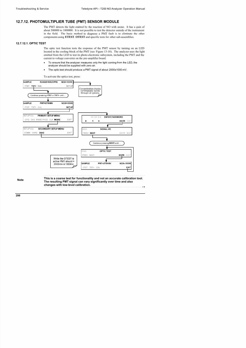
8/9/2019 06858D_T200
http://slidepdf.com/reader/full/06858dt200 300/476
Teledyne API – T200 NO Analyzer Operation Manual Troubleshooting & Service
12.7.12.2. ELECTRICAL TESTThe electrical test function creates a current, which is substituted for the PMT signal and
feeds it into the preamplifier board.
This signal is generated by circuitry on the pre-amplifier board itself and tests thefiltering and amplification functions of that assembly along with the A/D converter onthe motherboard.
It does not test the PMT itself.
The electrical test should produce a PMT signal of about 2000 ±1000 mV.
To activate the electrical test, press:

8/9/2019 06858D_T200
http://slidepdf.com/reader/full/06858dt200 301/476
Troubleshooting & Service Teledyne API – T200 NO Analyzer Operation Manual
12.7.13. PMT PREAMPLIFIER BOARDTo check the correct operation of the preamplifier board, perform an the optics test
(OTEST) and an electrical test (ETEST) described in Sections 12.7.12.1 and 12.7.12.2
above.
If the instrument passes the OTEST but fails the ETEST, the preamplifier boardmay be faulty or need a hardware calibration.
12.7.13.1. HIGH VOLTAGE POWER SUPPLY
The HVPS is located in the interior of the sensor module and is plugged into the PMT
tube. It requires 2 voltage inputs.
The first is +15 V, which powers the supply.
The second is the programming voltage which is generated on the preamplifierboard.
Adjustment of the HVPS is covered in the factory calibration procedure in Section12.8.4.
This power supply has 10 independent power supply steps, one to each pin of the PMT.
The following test procedure below allows you to test each step.
1. Turn off the instrument.
2. Remove the cover and disconnect the 2 connectors at the front of the NOX sensormodule.
3. Remove the end cap from the sensor (4 screws).
4. Remove the HVPS/PMT assembly from the cold block inside the sensor (2 plasticscrews).
5. Disconnect the PMT from the HVPS.
6 R t th 7 i t t th d d th

8/9/2019 06858D_T200
http://slidepdf.com/reader/full/06858dt200 302/476
6. Re-connect the 7 pin connector to the sensor end cap, and power-up theinstrument.
7. Scroll the front panel display to the HVPS test parameter.
8. Divide the displayed HVPS voltage by 10 and test the pairs of connector points asshown in the figure below.
9. Check the overall voltage (should be equal to the HVPS value displayed on the frontpanel and the voltages between each pair of pins of the supply
EXAMPLE
If the HVPS signal is 700 V the pin-to-pin voltages should be 70 V.
Teledyne API – T200 NO Analyzer Operation Manual Troubleshooting & Service
1. Turn off the instrument power, and reconnect the PMT, and then reassemble the sensor.
If any faults are found in the test, you must obtain a new HVPS as there are nouser serviceable parts inside the supply.
12.7.14. PMT TEMPERATURE CONTROL PCAThe TEC control PCA is located on the sensor housing assembly, under the slanted
shroud, next to the cooling fins and directly above the cooling fan.
If the red LED located on the top edge of this assembly is not glowing the control circuit
is not receiving power. Check the analyzers power supply, the relay board’s power
distribution circuitry and the wiring connecting them to the PMT temperature controlPCA.
TEC Control Test Points
Four test points are also located at the top of this assembly they are numbered left to
right start with the T1 point immediately to the right of the power status LED. These

8/9/2019 06858D_T200
http://slidepdf.com/reader/full/06858dt200 303/476
right start with the T1 point immediately to the right of the power status LED. These
test points provide information regarding the functioning of the control circuit.
To determine the current running through the control circuit, measure the voltage
between T1 and T2. Multiply that voltage by 10. To determine the drive voltage being supplied by the control circuit to the TEC,
measure the voltage between T2 and T3.
If this voltage is zero, the TEC circuitry is most likely open.
Or,
If the voltage between T2 and T3 = 0 VDC and the voltage measured betweenT1 and T2 = 0 VDC there is most likely an open circuit or failed op amp on
Troubleshooting & Service Teledyne API – T200 NO Analyzer Operation Manual
12.7.15. O3 GENERATORThe ozone generator can fail in two ways, electronically (printed circuit board) and
functionally (internal generator components). Assuming that air is supplied properly to
the generator, the generator should automatically turn on 30 minutes after the instrument
is powered up or if the instrument is still warm. See Section 13.2.3 for ozone generator
functionality. Accurate performance of the generator can only be determined with an
ozone analyzer connected to the outlet of the generator. However, if the generator
appears to be working properly but the sensitivity or calibration of the instrument is
reduced, suspect a leak in the ozone generator supply air.
A leak in the dryer or between the dryer and the generator can cause moist, ambient air
to leak into the air stream, which significantly reduces the ozone output. The generator
will produce only about half of the nominal O3 concentration when run with moist,
ambient air instead of dried air. In addition, moist supply air will produce large amounts
of nitric acid in the generator, which can cause analyzer components downstream of the
generator to deteriorate and/or causes significant deposit of nitrate deposits on the
reaction cell window, reducing sensitivity and causing performance drift. Carry out a
leak check as described earlier in this Section.
12.7.15.1. O3 GENERATOR OVERRIDE
This feature allows the user to manually turn the ozone generator off and on. This
should be done before disconnecting the generator, to prevent ozone from leaking out, or
after a system restart if the user does not want to wait for 30 minutes during warm-up
time. To access this feature press the following buttons: (Also note that the ozone
generator does not turn on if the ozone flow conditions are out of specification (e.g., ifthere is no flow through the system or the pump is broken).

8/9/2019 06858D_T200
http://slidepdf.com/reader/full/06858dt200 304/476
Teledyne API – T200 NO Analyzer Operation Manual Troubleshooting & Service

8/9/2019 06858D_T200
http://slidepdf.com/reader/full/06858dt200 305/476
Note This is one of the two settings in the DIAG menu that is retained after youexit the menu.
12.7.16. INTERNAL SPAN GAS GENERATOR AND VALVE OPTIONSThe zero/span valves and Internal span gas generator options need to be enabled in the
software (contact the factory on how to do this)
Troubleshooting & Service Teledyne API – T200 NO Analyzer Operation Manual
The semi-permeable PTFE membrane of the permeation tube is severely affected by
humidity. Variations in humidity between day and night are usually enough to yield
very variable output results. If the instrument is installed in an air-conditioned shelter,
the air is usually dry enough to produce good results. If the instrument is installed in an
environment with variable or high humidity, variations in the permeation tube output
will be significant. In this case, a dryer for the supply air is recommended (dew point
should be –20° C or less).
The permeation tube of the internal span gas generator option is heated with a
proportional heater circuit and the temperature is maintained at 50°C ±1C. Check thefront panel display or the IZS_TEMP signal voltage using the SIGNAL I/O function
under the DIAG Menu (Section 5.9.1). At 50° C, the temperature signal from the IZS
thermistor should be around 2500 mV.
12.7.17. TEMPERATURE SENSOR
12.7.17.1. BOX TEMPERATURE SENSOR
The box temperature sensor (thermistor) is mounted on the motherboard below the
bottom edge of the CPU board when looking at it from the front. It cannot be
disconnected to check its resistance.
Box temperature will vary with, but will usually read about 5° C higher than, ambient(room) temperature because of the internal heating zones from the NO2 converter,reaction cell and other devices.
To check the box temperature functionality, we recommend checking the
BOX_TEMP signal voltage using the SIGNAL I/O function under the DIAG Menu(Section 12.1.3).
At about 30° C, the signal should be around 1500 mV.
To check the accuracy of the sensor, use a calibrated external thermometer /temperature sensor to verify the accuracy of the box temperature by:

8/9/2019 06858D_T200
http://slidepdf.com/reader/full/06858dt200 306/476
Placing it inside the chassis, next to the thermistor labeled XT1 (aboveconnector J108) on the motherboard.
Compare its reading to the value of the test function PMT TEMP.
12.7.17.2. PMT TEMPERATURE SENSOR CONTROL
The temperature of the PMT should be low and constant. It is more important that this
temperature is maintained at a constant level than it is to be a specific temperature.
The PMT cooler uses a Peltier, thermo-electric cooler element supplied with 12 V DC
power from the switching power supply PS2. The temperature is controlled by a
proportional temperature controller located on the preamplifier board
Teledyne API – T200 NO Analyzer Operation Manual Troubleshooting & Service
2. Turn on the analyzer.
3. Set the front panel to show the PMT TEMP test function (see Section 4.1.1).
The temperature should fall steadily to 6-10° C.
If the temperature fails to reach this point after 60 minutes, there is a problem inthe cooler circuit.
If the control circuit on the preamplifier board is faulty, a temperature of –1° C will be reported.

8/9/2019 06858D_T200
http://slidepdf.com/reader/full/06858dt200 307/476
Troubleshooting & Service Teledyne API – T200 NO Analyzer Operation Manual
12.8. SERVICE PROCEDURESThis section contains some procedures that may need to be performed when a major
component of the analyzer requires repair or replacement.
Note Maintenance procedures (e.g., replacement of regularly changedexpendables) are discussed in Section 11 (Instrument Maintenance) andare not listed here).
Also, there may be more detailed service notes for some of the belowprocedures. Contact Teledyne API's Customer Service Department.
WARNING – ELECTRICAL SHOCK HAZARD
Unless the procedure being performed requires the instrument be operating, turn it
off and disconnect power before opening the analyzer and removing, adjusting orrepairing any of its components or subsystems.
CAUTION – QUALIFIED TECHNICIAN The operations outlined in this chapter are to be performed by qualified
maintenance personnel only.
12.8.1. DISK-ON-MODULE REPLACEMENT PROCEDURE
Note Servicing of circuit components requires electrostatic discharge

8/9/2019 06858D_T200
http://slidepdf.com/reader/full/06858dt200 308/476
Note Servicing of circuit components requires electrostatic dischargeprotection, i.e. ESD grounding straps, mats and containers. Failure to useESD protection when working with electronic assemblies will void the
instrument warranty. Refer to Section 14 for more information onpreventing ESD damage.
Replacing the Disk-on-Module (DOM) will cause loss of all DAS data; it may also
cause loss of some instrument configuration parameters unless the replacement DOM
carries the exact same firmware version. Whenever changing the version of installed
software, the memory must be reset. Failure to ensure that memory is reset can cause the
analyzer to malfunction, and invalidate measurements. After the memory is reset, the
Teledyne API – T200 NO Analyzer Operation Manual Troubleshooting & Service
3. While looking at the electronic circuits from the back of the analyzer, locate the Disk-
on-Module in the right-most socket of the CPU board.
4. The DOM should carry a label with firmware revision, date and initials of the
programmer.
5. Remove the nylon standoff clip that mounts the DOM over the CPU board, and lift
the DOM off the CPU. Do not bend the connector pins.
6. Install the new Disk-on-Module, making sure the notch at the end of the chip
matches the notch in the socket.7. It may be necessary to straighten the pins somewhat to fit them into the socket.
Press the chip all the way in.
8. Close the rear panel and turn on power to the machine.
9. If the replacement DOM carries a firmware revision, re-enter all of the setup
information.
12.8.2. O3 GENERATOR REPLACEMENTThe ozone generator is a black, brick-shaped device with printed circuit board attached
to its rear and two tubes extending out the right side in the front of the analyzer (see
Figure 3-5). The board has a red LED that, when lit, indicates ozone is being generated.
To replace the ozone generator:
1. Turn off the analyzer power, remove the power cord and the analyzer cover.
2. Disconnect the 1/8” black tube from the ozone cleanser and the ¼” clear tube from
the plastic extension tube at the brass fitting nearest to the ozone generator.3. Unplug the electrical connection on the rear side of the brick.
4. Unscrew the two mounting screws that attach the ozone generator to the chassisand take out the entire assembly.
5. If you received a complete replacement generator with circuit board and mountingbracket attached simply reverse the above steps to replace the current generator

8/9/2019 06858D_T200
http://slidepdf.com/reader/full/06858dt200 309/476
bracket attached, simply reverse the above steps to replace the current generator.
Note Ensure to carry out a leak check (11.3.12) and a recalibration after the
analyzer has warmed up for about 60 minutes.
12.8.3. SAMPLE AND OZONE (PERMA PURE ® ) DRYER REPLACEMENTThe T200 standard configuration is equipped with a dryer for the ozone supply air. An
optional dryer is available for the sample stream and a combined dryer for both gas
Troubleshooting & Service Teledyne API – T200 NO Analyzer Operation Manual
3. Disconnect all tubing that extends out of the dryer assembly.
Take extra care not to twist any of the white plastic fittings on the dryer.
These connect the inner drying tube to the outer purge tube and are delicate.See Sections 13.3.1 and 11.3.2.
4. Note the orientation of the dryer on the bracket.
5. Cut the tie wraps that hold the dryer to the mounting bracket and take out the olddryer.
If necessary, unscrew the two mounting screws on the bracket and take out theentire assembly.
6. Attach the replacement dryer to the mounting bracket in the same orientation as theold dryer.
7. Fix the dryer to the bracket using new tie wraps.
8. Cut off excess length of the wraps.
9. Put the assembly back into the chassis and tighten the mounting screws.
10. Re-attach the tubes to vacuum manifold, flow meter and/or NO/NOx valve using atleast two wrenches.
Take extra care not to twist the dryer’s white plastic fittings, as this will result inlarge leaks that are difficult to trouble-shoot and fix.
11. Carry out a detailed leak check (see Section 11.3.12.2),
12. Close the analyzer.
13. Power up pump and analyzer and re-calibrate the instrument after it stabilizes.
12.8.4. PMT SENSOR HARDWARE CALIBRATIONThe sensor module hardware calibration is used in the factory to adjust the slope and
offset of the PMT output and to optimize the signal output and HVPS.

8/9/2019 06858D_T200
http://slidepdf.com/reader/full/06858dt200 310/476
If the instrument’s slope and offset values are outside of the acceptable range andall other more obvious causes for this problem have been eliminated, the hardware
calibration can be used to adjust the sensor as has been done in the factory. This procedure is also recommended after replacing the PMT or the preamplifier
board.
To calibrate the PMT preamplifier PCA:
1. Perform a full zero point calibration using zero air (see Section 9).
2. Display the NOX STB test function on the front panel (Section 4.1.1).
Teledyne API – T200 NO Analyzer Operation Manual Troubleshooting & Service
6. Feed NO gas into the analyzer.
This should be 90% of the upper limit setting for the T200’s reporting range:
EXAMPLE: if the reporting range is set at 500 ppb, use 450 ppb NO.
7. Wait until the STB value is below 0.5 ppb
Figure 12-8: Pre-Amplifier Board Layout
8. Scroll to the NORM PMT test function on the analyzer’s front panel.
9. With the NO gas concentrations mentioned in Step 5 above, the norm pmt value
should be 900 mV.
10. Set the HVPS coarse adjustment to its minimum setting (0).
11. Set the HVPS fine adjustment switch to its maximum setting (F).
Set the HVPS coarse adjustment switch to the lowest setting that will give you just above the target value for NORM PMT signal.

8/9/2019 06858D_T200
http://slidepdf.com/reader/full/06858dt200 311/476
12. Adjust the HVPS fine adjustment such that the NORM PMT value is close to thetarget value.
It may be necessary to go back and forth between coarse and fine adjustmentsif the proper value is at the threshold of the min/max coarse setting.
ATTENTION COULD DAMAGE INSTRUMENT AND VOID WARRANTYDo not overload the PMT by accidentally setting both adjustment switchesto their maximum setting. Start at the lowest setting and increment
Troubleshooting & Service Teledyne API – T200 NO Analyzer Operation Manual
13. Perform a span point calibration (see Section 9) to normalize the sensor responseto its new PMT sensitivity.
14. Review the slope and offset values:
The slope values should be 1.000±0.300.
The offset values should be approximately 0.0 (-20 to +150 mV is allowed).
12.8.5. REPLACING THE PMT, HVPS OR TECThe photo multiplier tube (PMT) should last for the lifetime of the analyzer, however,
the high voltage power supply (HVPS) or the thermo-electric cooler (TEC) components
may fail. Replacing any of these components requires opening the sensor module. This
is a delicate assembly and it is recommend that you ensure the PMT, HVPS or TEC
modules are, indeed, faulty before unnecessarily opening of the module.
CAUTION QUALIFIED PERSONNEL
While the PMT or HVPS can be removed through the front panel without un-mounting the entire sensor module, we recommend turning off the instrument,
opening its top cover and removing the entire assembly so that further repairs canbe carried out at an anti-ESD workstation.
Follow the guidelines defined in Section14for preventing electrostatic damage toelectronic components.
1. Turn OFF the analyzer and disconnect the power cord.
2. Remove the cover.
3. Disconnect all pneumatic and electrical connections from the sensor assembly.
4. Remove the sensor assembly.
5. If the TEC is to be replaced, remove the reaction cell assembly at this point by

8/9/2019 06858D_T200
http://slidepdf.com/reader/full/06858dt200 312/476
unscrewing two holding screws.
This is necessary only if the repair being performed involves removing the PMT
cold block.
Teledyne API – T200 NO Analyzer Operation Manual Troubleshooting & Service
Figure 12-9: T200 Sensor Assembly
6. Remove the two connectors on the PMT housing end plate facing towards the frontpanel.
7. Remove the end plate itself (4 screws with plastic washers).
Note If the black PMT housing end plate for the Sensor Assembly is removed,ensure to replace the 5 desiccant bags inside the housing.

8/9/2019 06858D_T200
http://slidepdf.com/reader/full/06858dt200 313/476
ensure to replace the 5 desiccant bags inside the housing.
8. Remove the dryer packages inside the PMT housing.9. Unscrew the PMT assembly, which is held to the cold block by two plastic screws.
10. Discard the plastic screws and replace with new screws at the end of this procedure(the threads get stripped easily and it is recommended to use new screws).
11. Along with the plate, slide out the OPTIC TEST LED and the thermistor thatmeasures the PMT temperature.
Thermistor will be coated with a white, thermal conducting paste.
Do not contaminate the inside of the housing with this grease as it may
Troubleshooting & Service Teledyne API – T200 NO Analyzer Operation Manual
15. Remove the end plate with the cooling fins (4 screws) and slide out the PMT cold
block assembly, which contains the TEC.
16. Unscrew the TEC from the cooling fins and the cold block and replace it with a newunit.
17. Reassemble this TEC subassembly in reverse order.
Ensure to use thermal grease between TEC and cooling fins as well as betweenTEC and cold block and that the side opening in the cold block will face thereaction cell when assembled.
Evenly tighten the long mounting screws for good thermal conductivity.
CAUTION QUALIFIED PERSONNEL
The thermo-electric cooler needs to be mounted flat to the heat sink.
If there is any significant gap, the TEC might burn out. Ensure to apply heat sinkpaste before mounting it and tighten the screws evenly and cross-wise.
18. Reinsert the TEC subassembly in reverse order.
Ensure that the O-ring is placed properly and the assembly is tightened evenly.
19. Insert the LED and thermistor into the cold block, insert new drying packages andcarefully replace the end plate by making sure that the O-ring is properly in place.
Improperly placed O-rings will cause leaks, which – in turn – cause moisture tocondense on the inside of the cooler and likely cause a short in the HVPS.
20. Reinsert the PMT/HVPS subassembly in reverse order.
Don’t forget the gasket between HVPS and PMT.
Use new plastic screws to mount the PMT assembly on the PMT cold block.
21. Install new silica gel packets (desiccant bags).
22 Reconnect the cables and the reaction cell (evenly tighten these screws)

8/9/2019 06858D_T200
http://slidepdf.com/reader/full/06858dt200 314/476
22. Reconnect the cables and the reaction cell (evenly tighten these screws).
23. Replace the sensor assembly into the chassis and fasten with four screws and
washers.24. Reconnect all electrical and pneumatic connections.
25. Leak check the system (see Section 13.3.12).
26. Turn ON the analyzer.
27. Verify the basic operation of the analyzer using the ETEST(12.7.12.2) and OTESTfeatures (12.7.12.1) or zero and span gases, then carry out a hardware calibrationof the analyzer followed by a zero/span point calibration (See Section 9.4.3.2).
Teledyne API – T200 NO Analyzer Operation Manual Troubleshooting & Service
12.8.6. REMOVING / REPLACING THE RELAY PCA FROM THEINSTRUMENTThis is the most commonly used version of the Relay PCA. It includes a bank of solid
state AC relays. This version is installed in analyzers where components such as AC
powered heaters must be turned ON & OFF.
A retainer plate is installed over the relay to keep them securely seated in their sockets.
AC RelayRetainer Plate
Retainer
MountingScrews
Figure 12-10: Relay PCA with AC Relay Retainer In Place
The Relay retainer plate installed on the relay PCA covers the lower right mounting
screw of the relay PCA. Therefore, when removing the relay PCA, the retainer plate
must be removed first.

8/9/2019 06858D_T200
http://slidepdf.com/reader/full/06858dt200 315/476
MountingScrews
Troubleshooting & Service Teledyne API – T200 NO Analyzer Operation Manual
12.9. FREQUENTLY ASKED QUESTIONSThe following list was compiled from the Teledyne API's Customer Service
Department’s 10 most commonly asked questions relating to the T200 NOx Analyzer.
QUESTION ANSWER
Why does the ENTR buttonsometimes disappear on the frontpanel display?
Sometimes the ENTR button will disappear if you select a setting that isinvalid or out of the allowable range for that parameter, such as trying to setthe 24-hour clock to 25:00:00 or a range to less than 1 or more than 20000ppb. Once you adjust the setting to an allowable value, the ENTR buttonwill re-appear.
Why is the ZERO or SPAN buttonnot displayed during calibration?
The T200 disables certain these buttons expected span or zero valueentered by the users is too different from the gas concentration actuallymeasured value at the time. This is to prevent the accidental recalibrationof the analyzer to an out-of-range response curve.
EXAMPLE: The span set point is 400 ppb but gas concentration beingmeasured is only 50 ppb.
How do I enter or change thevalue of my Span Gas?
Press the CONC button found under the CAL or CALS buttons of the mainSAMPLE display menus to enter the expected NOx span concentration.
See Section 9.2.3.1 or for more information.
Can I automate the calibration ofmy analyzer?
Any analyzer with zero/span valve or IZS option can be automaticallycalibrated using the instrument’s AutoCal feature.
Can I use the IZS option tocalibrate the analyzer?
Yes. However, the accuracy of the IZS option’s permeation tube is only±5%. Whereas this may be acceptable for basic calibration checks, the IZSoption is not permitted as a calibration source in applications following USEPA protocols.

8/9/2019 06858D_T200
http://slidepdf.com/reader/full/06858dt200 316/476
To achieve highest accuracy, it is recommended to use cylinders of
calibrated span gases in combination with a zero air source.
How do I measure the sampleflow?
Sample flow is measured by attaching a calibrated flow meter to the sampleinlet port when the instrument is operating. The sample flow should be 500
cm³/min 10%.
Section 13.3.12.3 includes detailed instructions on performing a check ofthe sample gas flow.
Teledyne API – T200 NO Analyzer Operation Manual Troubleshooting & Service
QUESTION ANSWER
How long does the sample pumplast?
The sample pump should last one to two years and the pump head shouldbe replaced when necessary. Use the RCEL pressure indicator on the frontpanel to see if the pump needs replacement.
If this value goes above 10 in-Hg-A, on average, the pump head needs tobe rebuilt.
Why does my RS-232 serialconnection not work?
There are several possible reasons:
The wrong cable: please use the provided or a generic “straight-through” cable (do not use a “null-modem” type cable) and ensure thepin assignments are correct (Sections 3.3.1.8 and 6.3).
The DCE/DTE switch on the back of the analyzer is not set properly;ensure that both green and red lights are on (Section 6.1).
The baud rate of the analyzer’s COMM port does not match that of theserial port of your computer/data logger (Section 6.2.2).
How do I make the instrument’sdisplay and my data loggeragree?
This most commonly occurs when an independent metering device is usedbesides the data logger/recorder to determine gas concentration levelswhile calibrating the analyzer. These disagreements result from theanalyzer, the metering device and the data logger having slightly differentground levels.
Use the data logger itself as the metering device during calibrationprocedures.
Do the critical flow orifices of myanalyzer require regularreplacement?
No. The o-rings and the sintered filter associated with them requirereplacement once a year, but the critical flow orifices do not.
See Section 11 for instructions.
How do I set up and use theContact Closures (Control Inputs)
See Section 3.3.1.6.

8/9/2019 06858D_T200
http://slidepdf.com/reader/full/06858dt200 317/476
Contact Closures (Control Inputs)on the Rear Panel of theanalyzer?
Troubleshooting & Service Teledyne API – T200 NO Analyzer Operation Manual
12.10. TECHNICAL ASSISTANCEIf this manual and its troubleshooting & service section do not solve your problems,
technical assistance may be obtained from:
Teledyne API, Technical Support,9480 Carroll Park DriveSan Diego, California 92121-5201USA
Toll-free Phone: 800-324-5190
Phone: 858-657-9800Fax: 858-657-9816
Email: [email protected]
Website: http://www.teledyne-api.com/
Before you contact Teledyne API's Customer Service, fill out the problem report form in
Appendix C, which is also available online for electronic submission at
http://www.teledyne-api.com/manuals/.

8/9/2019 06858D_T200
http://slidepdf.com/reader/full/06858dt200 318/476
13. PRINCIPLES OF OPERATIONThe T200 Nitrogen Oxides Analyzer is a microprocessor controlled instrument that
determines the concentration of nitric oxide (NO), total nitrogen oxides (NOX, the sum
of NO and NO2) and nitrogen dioxide (NO2) in a sample gas drawn through the
instrument.
It requires that sample and calibration gases be supplied at ambient atmospheric
pressure in order to establish a constant gas flow through the reaction cell wherethe sample gas is exposed to ozone (O3), initiating a chemical reaction that gives offlight (hv).
The instrument measures the amount of chemiluminescence to determine theamount of NO in the sample gas.
A catalytic-reactive converter converts NO2 in the sample gas to NO which, alongwith the NO present in the sample is reported as NOX. NO2 is calculated as thedifference between NOX and NO.
Calibration of the instrument is performed in software and usually does not require
physical adjustments to the instrument. During calibration, the microprocessor measures
the sensor output signal when gases with known amounts of NO or NO2 are supplied
and stores these results in memory. The microprocessor uses these calibration values
along with the signal from the sample gas and data of the current temperature and
pressure of the gas to calculate a final NOX concentration.

8/9/2019 06858D_T200
http://slidepdf.com/reader/full/06858dt200 319/476
The concentration values and the original information from which it was calculated are
stored in the unit’s internal data acquisition system (DAS Section 7) and are reported tothe user through a vacuum fluorescence display or several output ports.
13.1. MEASUREMENT PRINCIPLE
13.1.1. CHEMILUMINESCENCE CREATION IN THE T200 REACTION CELLTh T200’ h f NO i b d i h
Principles of Operation Teledyne API – T200 NO Analyzer Operation Manual
Equation 13-1
2*23 ONOONO
The second step occurs because the laws of thermodynamics require that systemsseek the lowest stable energy state available, therefore the excited NO2 moleculequickly returns to its ground state, releasing the excess energy. This release takes
the form of a quantum of light (h). The distribution of wavelengths for these quanta
range between 600 and 3000 nm, with a peak at about 1200 nm.
Equation 13-2
nmhNONO 12002*2
All things being constant (temperature, pressure, amount of ozone present, etc.), the
relationship between the amount of NO present in the reaction cell and the amount of
light emitted from the reaction is very linear. If more NO is present, more IR light is
produced. By measuring the amount of IR light produced with a sensor sensitive in the
near-infrared spectrum (see Figure 13-2) the amount of NO present can be determined.
In addition, sometimes the excited NO2 collides with other gaseous molecules in the
reaction cell chamber or even the molecules of the reaction cell walls and transfers its
excess energy to this collision partner (represented by M in the equation 12-3 below)
without emitting any light at all. In fact, by far the largest portion of the excited NO2 returns to the ground state this way, leaving only a few percent yield of usable
chemiluminescence.
Equation 13-3
MNOMNO 2*2

8/9/2019 06858D_T200
http://slidepdf.com/reader/full/06858dt200 320/476
The probability of a collision between the NO2* molecule and a collision partner M increases proportionally with the reaction cell pressure. This non-radiating collision
with the NO2* molecules is usually referred to as third body quenching, an unwanted
process further described in Section 13.1.5.2.
Even under the best conditions only about 20% of the NO2 that is formed by the reaction
described in equation 12-1 is in the excited state. In order to maximize
chemiluminescence, the reaction cell is maintained at reduced pressure (thereby
reducing the amount of available collision partners) and is supplied with a large
Teledyne API – T200 NO Analyzer Operation Manual Principles of Operation
13.1.2. CHEMILUMINESCENCE DETECTION IN THE T200 REACTION CELL
13.1.2.1. THE PHOTO MULTIPLIER TUBE (PMT)
The T200 uses a special kind of vacuum tube, called a photo-multiplier tube (PMT), to
detect the amount of light created by the NO and O3 reaction in the reaction cell.
Photons enter the PMT and strike a negatively charged photo cathode causing it to emit
electrons. These electrons are accelerated by an applied high voltage and multiplied
through a sequence of similar acceleration steps (dynodes) until a useable current signal
is generated (see Section 13.5 for a more detailed description). The more light present
(in this case photons given off by the chemiluminescent reaction described above), the
more current is produced. Therefore the more NO present in the reaction cell the more
current is produced by the PMT.
The current produced by the PMT is converted to a voltage and amplified by the
preamplifier board and then communicated to the T200’s CPU via the A D converter
circuitry on the analyzer.
13.1.2.2. OPTICAL FILTERA high pass optical filter, only transparent to wavelengths of light above 645nm, placed
between the reaction cell and the PMT (see Figure 13-1) in conjunction with the
response characteristics of the PMT creates a very narrow window of wavelengths of
light to which the T200 will respond.

8/9/2019 06858D_T200
http://slidepdf.com/reader/full/06858dt200 321/476
Figure 13-1: Reaction Cell with PMT Tube and Optical Filter
The narrowness of this band of sensitivity allows the T200 to ignore extraneous light
Principles of Operation Teledyne API – T200 NO Analyzer Operation Manual
0
20
40
60
80
100
120
140
0.5 0.9 1.1 1.3 1.5 1.7 1.9
Wavelength (micrometers)
n
e n s
y ( a r b i t r a r y
u n i t s )
Optical Hi-Pass Filter Performance
NO + O3 Emission Spectrum
Area of Sensitivity
InfraredVisible
Spectrum
PMT
Response
0.7
Figure 13-2: T200 Sensitivity Spectrum
13.1.3. NOX AND NO2 DETERMINATIONThe only gas that is actually measured by the T200 is NO. NO2, and therefore NOx
(which is defined here as the sum of NO and NO2 in the sample gas), contained in the
gas is not detected because NO2 does not react with O3 to create chemiluminescence.
In order to measure the concentration of NO2, and therefore the concentration of NOx,
the T200 periodically switches the sample gas stream so that the pump pulls it through a
special converter cartridge filled with molybdenum (Mo, “moly”) chips that are heated
to a temperature of 315°C.
31
2NO only

8/9/2019 06858D_T200
http://slidepdf.com/reader/full/06858dt200 322/476
NO/NOX
VALVE AUTOZERO
VALVE
NO2 + Mo NO+ MoyOz
at 315˚C
1
13
2
O3 from
O3 Generator MOLYBDENUM
CONVERTER
To Exhaust
Manifold & Pump
Teledyne API – T200 NO Analyzer Operation Manual Principles of Operation
The heated molybdenum reacts with NO2 in the sample gas and produces a NO gas and
a variety of molybdenum.
Equation 13-4
)315(2 CatOMxNOyMoxNO zy
Once the NO2 in the sample gas has been converted to NO, it is routed to the reaction
cell where it undergoes the chemiluminescence reaction described in Equation 13-1 and
Equation 13-2.
By converting the NO2 in the sample gas into NO, the analyzer can measure the total
NOX) content of the sample gas (i.e. the NO present + the converted NO2 present). By
switching the sample gas stream in and out of the “moly” converter every 6 - 10
seconds, the T200 analyzer is able to quasi-continuously measure both the NO and the
total NOX content.
Finally, the NO2 concentration is not directly measured but calculated by subtracting the
known NO content of the sample gas from the known NOX content.
13.1.4. AUTO ZEROInherent in the operation of any PMT is a certain amount of noise. This is due to a
variety of factors such as black body infrared radiation given off by the metal
components of the reaction cell, unit to unit variations in the PMT units and even the
constant universal background radiation that surrounds us at all times. In order to
reduce this amount of noise and offset, the PMT is kept at a constant 7° C (45° F) by aThermo-Electric Cooler (TEC).
While this intrinsic noise and offset is significantly reduced by cooling the PMT, it is
not eradicated. To determine how much noise remains, once every minute for about 8
seconds the T200 diverts the sample gas flow directly to the vacuum manifold without
passing the reaction cell.

8/9/2019 06858D_T200
http://slidepdf.com/reader/full/06858dt200 323/476
During this time, only O3 is present in the reaction cell, effectively turning off the
chemiluminescence reaction. Once the chamber is completely dark, the T200 recordsthe output of the PMT and keeps a running average of these AZERO values. This
average offset value is subtracted from the raw PMT readings while the instrument is
measuring NO and NOX to arrive at an Auto Zero corrected reading.
Principles of Operation Teledyne API – T200 NO Analyzer Operation Manual
Figure 13-4: Pneumatic Flow During the Auto Zero Cycle
13 1 5 MEASUREMENT INTERFERENCES

8/9/2019 06858D_T200
http://slidepdf.com/reader/full/06858dt200 324/476
13.1.5. MEASUREMENT INTERFERENCES
It should be noted that the chemiluminescence method is subject to interferences from anumber of sources. The T200 has been successfully tested for its ability to reject
interference from most of these sources. Table 13-1 list the most common types of
interferents that could affect the performance of your T200.
13.1.5.1. DIRECT INTERFERENCE
Some gases can directly alter the amount of light detected by the PMT due to
Teledyne API – T200 NO Analyzer Operation Manual Principles of Operation
Quenching is an unwanted phenomenon and the extent to which it occurs depends on the
properties of the collision partner.
Larger, more polarized molecules such as H2O and CO2 are the most significantquenching interferents of NO chemiluminescence.
The influence of water vapor on the T200 measurement can be eliminated withan optional, internal sample gas dryer (see Section 3.3.2.6).
The interference of varying CO2 amounts at low concentrations (less that 0.5%)is negligible.
In cases with excessively high CO2 concentrations (larger than 0.5%), the effect
can be calibrated out by using calibration gases with a CO2 content equal to themeasured air.
Only very high and highly variable CO2 concentrations will then cause ameasurable interference. For those applications, it is recommended to useother analyzer models. Please consult Teledyne API's Sales Department or ourwebsite (see Section 12.10).
Smaller less polar and electronically “harder” molecules such as N2 and O2 cancause interference of this type as well, however, the concentrations of N2 and O2 are virtually constant in ambient air measurements, hence provide a constant
amount of quenching that is accounted for in the calibration of the instrument .
13.1.5.3. LIGHT LEAKS
The T200 sensitivity curve includes a small portion of the visible light spectrum (see
Figure 13-2), therefore it is important to ensure that the reaction cell is completely
sealed with respect to light. To ensure this:
All pneumatic tubing leading into the reaction cell is opaque in order to prevent light
from entering the cell. Light penetration is prevented by stainless steel filters and orifices.

8/9/2019 06858D_T200
http://slidepdf.com/reader/full/06858dt200 325/476
Principles of Operation Teledyne API – T200 NO Analyzer Operation Manual
Table 13-1: List of Interferents
Gas Interference Type Rejection Method
Dilution: Viscosity of CO2 molecules causes them tocollect in aperture of Critical Flow Orifice altering flowrate of NO.
CO2 3
rd Body Quenching: CO2 molecules collide with
NO2* molecules absorbing excess energy kineticallyand preventing emission of photons.
If high concentrations of CO2 are suspected,special calibration methods must be performed toaccount for the affects of the CO2.
Contact Teledyne API’s Customer ServiceDepartment (see Section 12.10) for details.
Some SOX variants can also initiate achemiluminescence reaction upon exposure to O3 producing excess light.
Wavelengths of light produced bychemiluminescence of SOX are screened out bythe Optical Filter.
Chemically reacts with NH3, O2 and H2O in O3 generator to create (NH3)2SO4 (ammonium sulfate)and NH3NO2 (ammonium nitrate) which form opaquewhite deposits on optical filter window. Also formshighly corrosive HNO3 (Nitric Acid)
Most of the ammonium sulfate and ammoniumnitrate produced is removed from the sample gasby an air purifier located between the O3 Generator and the reaction cell.SOX
3rd
Body quenching: SOX molecules collide with NO2*molecules absorbing excess energy kinetically andpreventing emission of photons.
If high concentrations of SOX are suspected,special calibration methods must be performed toaccount for the affects of the SO2.
Contact Teledyne API’s Customer Service
Department (see Section 12.10) for details.
3rd
Body quenching: H2O molecules collide with NO2*molecules absorbing excess energy kinetically andpreventing emission of light.
Analyzer’s operating in high humidity areas musthave some drying applied to the sample gas (seeSection 3.3.2.6 for more details).
H2O Water also reacts with NH3 and SOX in the O3 generator to create (NH3)2SO4 (ammonium sulfate)and NH3NO2 (ammonium nitrate) which form opaquewhite deposits on the optical filter window. This alsoforms highly corrosive HNO3 (nitric acid)
Water is effectively removed from the O3 gasstream by the Perma Pure
® Dryer (Section
13.2.3.2 for more details). We offer severalPerma Pure
® dryers for the sample stream (see
Section 3.3.2.6 for more details).
Direct Interference: NH3 is converted to H2O and NOby the NO2 converter. Excess NO reacts with O3 inthe reaction cell creating a chemiluminescenceartifact.
If a high concentration of NH3 is suspected, stepsmust be taken to remove the NH3 from the samplegas prior to its entry into the NO2 converter (seeSection 3.3.2.6 for more details).
NH3 NH3 also reacts with H2O, O2 and SOX in the O3 generator to create (NH3)2SO4 (ammonium sulfate)and NH3NO2 (ammonium nitrate) which form opaquewhite deposits on optical filter window. Also formshighly corrosive HNO3 (nitric acid).
The Perma Pure® dryer built into the T200 is
sufficient for removing typical ambientconcentration levels of NH3.

8/9/2019 06858D_T200
http://slidepdf.com/reader/full/06858dt200 326/476
13.1.5.4. REACTION CELL TEMPERATURE CONTROL
The stability of the chemiluminescence reaction between NO and O3 can be affected by
changes in the temperature and pressure of the O3 and sample gases in the reaction cell.
In order to reduce temperature effects, the reaction cell is maintained at a constant
50 C just above the high end of the instrument’s operation temperature range
Teledyne API – T200 NO Analyzer Operation Manual Principles of Operation
13.2. PNEUMATIC OPERATION
IMPORTANT IMPACT ON READINGS OR DATA Could either affect accuracy of instrument readings or cause loss of data.
Note The sample gas is the most critical flow path in the analyzer. At any pointbefore and in the reaction cell, the integrity of the sample gas cannot becompromised. Therefore, it is important that the sample airflow system isboth leak tight and not pressurized over ambient pressure.
Regular leak checks should be performed on the analyzer as presented in the
maintenance schedule, Table 13-1. Procedures for correctly performing leak checks can
be found in Section 13.3.12.
13.2.1. SAMPLE GAS FLOW
Note In this section of the manual vacuum readings are given in inches ofmercury absolute (In-Hg-A). This pressure value is referenced againstzero (a perfect vacuum).
The gas flow for the T200 is created by a pump that is pneumatically downstream fromthe rest of the instrument’s components. This is either:
An external pump pneumatically connected to the analyzer’s exhaust port locatedon the rear panel. This is the most common configuration for the T200 or,
An optional internal pump pneumatically connected between the vacuum manifoldand the exhaust outlet (special order).
I ith th t f i t l 5 i H A t t d d

8/9/2019 06858D_T200
http://slidepdf.com/reader/full/06858dt200 327/476
In either case the pump creates a vacuum of approximately 5 in-Hg-A at one standard
liter/minute, which is provided to various pneumatic components by a vacuum manifoldlocated just in front of the rear panel (see Figure 3-5).
Gas flow is created by keeping the analyzer’s sample gas inlet near ambient pressure,
usually by means of a small vent installed in the sample line at the inlet, in effect pulling
the gas through the instrument’s pneumatic systems.
By placing the pump downstream from the analyzer’s reaction cell, several problems are
avoided.
Principles of Operation Teledyne API – T200 NO Analyzer Operation Manual
13.2.1.1. VACUUM MANIFOLD
The vacuum created by the analyzer’s pump is supplied to all of the gas streams for the
T200 analyzer through the vacuum manifold (also called the exhaust manifold).
Figure 13-5. Vacuum Manifold, Standard Configuration
Configurations will vary depending on the optional equipment that is installed. For
example:
An T200 with the optional internal span gas generator installed will add another FT8connector and orifice assembly to the manifold where the FT28 fitting is shown inthe above drawing.
An optional sample gas dryer will add a Tee-fitting so that two ¼” tubes can beconnected to the same port.
13.2.1.2. SAMPLE GAS FLOW VALVES AND ROUTING
As discussed in Section 13.1, the measurement of NOx, NO and NO2 requires that the
sample gas flow cycles through different routes that include and exclude various

8/9/2019 06858D_T200
http://slidepdf.com/reader/full/06858dt200 328/476
sample gas flow cycles through different routes that include and exclude various
scrubbers and converters. There are several valves that perform this function:
The NO/NOX valve directs the sample gas either directly to the reaction cell orthrough the unit’s NO2 converter, alternating every ~8 sec.
The Auto Zero valve directs the sample gas stream to completely bypass thereaction cell for dark noise measurement once every minute, which is thensubtracted as a measurement offset from the raw concentration signal.
Teledyne API – T200 NO Analyzer Operation Manual Principles of Operation
Table 13-2: T200 Valve Cycle Phases
Phase
NO/ NOX
ValveStatus
Auto Zero
ValveStatus
TimeIndex Activity Figure
0 - 2 sWait period (NO dwell time). Ensures reaction cell has
been flushed of previous gas.NOMeasure
Open to Auto Zero
valve
Open toreaction cell
2 - 4 s Analyzer measures chemiluminescence in reaction cell.
Figure13-3
4 – 6 sWait period (NOX dwell time). Ensures reaction cell has
been flushed of previous gas.NOX Measure
Open toNO2
converter
Open toreaction cell
6 – 8 s Analyzer measures NO + O3 chemiluminescence in
reaction cell.
Figure13-3
Cycle repeats every ~8 seconds
0 – 4 sWait period (AZERO dwell time). Ensures reaction cell
has been flushed of sample gas and chemi-luminescence reaction is stopped. Auto
Zero
Open to Auto Zero
valve
Open tovacuummanifold
4 - 6 s Analyzer measures background noise without sample
gas
Figure13-4
Cycle repeats every minute
13.2.2. FLOW RATE CONTROL - CRITICAL FLOW ORIFICESSample gas flow in the T200 analyzer is created via the use of several flow control
assemblies (see Figure 13-6 for an example) located in various places in the gas streams
of the instrument. These assemblies consist of:
a critical flow orifice
two o-rings, Located just before and after the critical flow orifice, the o-rings seal the
gap between the walls of assembly housing and the critical flow orifice a sintered filter
a spring (applies mechanical force needed to form the seal between the o-rings, thecritical flow orifice and the assembly housing)

8/9/2019 06858D_T200
http://slidepdf.com/reader/full/06858dt200 329/476
Principles of Operation Teledyne API – T200 NO Analyzer Operation Manual
13.2.2.1. CRITICAL FLOW ORIFICE
The most important component of each flow control assembly is the critical flow orifice.
Critical flow orifices are a simple means to regulate stable gas flow rates. They operate
without moving parts by taking advantage of the laws of fluid dynamics. By restricting
the flow of gas through the orifice, a pressure differential is created. This pressure
differential, created by the analyzer’s external pump, draws the gas through the orifice.
As the pressure on the downstream side of the orifice (the pump side) continues to drop,
the speed that the gas flows though the orifice continues to rise. Once the ratio of
upstream pressure to downstream pressure is greater than 2:1, the velocity of the gas
through the orifice reaches the speed of sound. As long as that ratio stays at least 2:1,the gas flow rate is unaffected by any fluctuations, surges, or changes in downstream
pressure because such variations only travel at the speed of sound themselves and are
therefore cancelled out by the sonic shockwave at the downstream exit of the critical
flow orifice.
The actual flow rate of gas through the orifice (volume of gas per unit of time), depends
on the size and shape of the aperture in the orifice. The larger the hole, the more gas
molecules (moving at the speed of sound) pass through the orifice.
In addition to controlling the gas flow rates into the reaction cell, the two critical flow
orifices at the inlets of the reaction cell also maintain an under-pressure inside it,
effectively reducing the number of molecules in the chamber and the corresponding
incidence of third body quenching (see Section 13.1.5.2) and therefore increasing the
chemiluminescence yield.
The T200 reaches its peak sensitivity at about 2 in-Hg-A, below which the sensitivitydrops due to there being too few molecules present and a corresponding decreasein chemiluminescence.
13.2.2.2. LOCATIONS AND DESCRIPTIONS OF CRITICAL FLOW ORIFICES INSIDE THE T200
The T200 uses several of the following critical flow orifices (Figure 13-7) to create and
maintain the proper flow rate of gas through its various components. (Please note that
Figure 13-7 represents the standard configuration and is provided for reference).

8/9/2019 06858D_T200
http://slidepdf.com/reader/full/06858dt200 330/476
Teledyne API – T200 NO Analyzer Operation Manual Principles of Operation
Figure 13-7: Location of Flow Control Assemblies & Critical Flow Orifices
Table 13-3: T200 Gas Flow Rates
Location PurposeOrifice
DiameterFlow rate(nominal)
Sample gas inlet of reaction cellControls rate of flow of sample gas into thereaction cell.
0.010” (0.25 mm) 500 cm³/min

8/9/2019 06858D_T200
http://slidepdf.com/reader/full/06858dt200 331/476
O3 supply inlet of reaction cellControls rate of flow of ozone gas into thereaction cell. 0.004” (0.10 mm) 80 cm³/min
Dry air return of Perma Pure® dryer
Controls flow rate of dry air return / purgeair of the dryer.
0.004” (0.10 mm) 80 cm³/min
Vacuum manifold, Auto Zero port.Controls rate of sample gas flow whenbypassing the reaction cell during the AutoZero cycle.
0.010” (0.25 mm) 500 cm³/min
Vacuum manifold, Internal span gasgenerator exhaust port
Controls rate of flow of zero purge gasthrough the optional Internal span gasgenerator when it is installed.
0.003” (0.10 mm) 60 cm³/min
Principles of Operation Teledyne API – T200 NO Analyzer Operation Manual
Note The diameter of a critical flow orifice may change with temperature
because of expansion of the orifice material and, hence, the most crucialcritical flow orifices in the T200 (those controlling the sample gas and O3flow into the cell itself) are located in the reaction cell where they can bemaintained at a constant temperature.
13.2.3. OZONE GAS GENERATION AND AIR FLOWThe excess ozone needed for reaction with NO in the reaction cell is generated inside the
analyzer because of the instability and toxicity of ozone. Besides the ozone generator
itself, this requires a dry air supply and filtering of the gas before it is introduced into the
reaction cell.
Due to its toxicity and aggressive chemical behavior, O3 must also be removed from the
gas stream before it can be vented through the exhaust outlet.
CAUTIONGENERAL SAFETY HAZARD
Ozone (O3) is a toxic gas.
Obtain a Material Safety Data Sheet (MSDS) for this gas. Read andrigorously follow the safety guidelines described there.
Always ensure that the plumbing of the O3 generation and supply systemis maintained and leak-free.
13.2.3.1. THE O3 GENERATOR
The T200 uses a dual-dielectric, Corona Discharge (CD) tube for creating its O 3, which
is capable of producing high concentrations of ozone efficiently and with low excess
heat (see Figure 13-8). The primary component of the generator is a glass tube with

8/9/2019 06858D_T200
http://slidepdf.com/reader/full/06858dt200 332/476
( g ) p y p g g
hollow walls of which the outermost and innermost surfaces are coated with electricallyconductive material.
Air flows through the glass tube, between the two conductive coatings, in effect creating
a capacitor with the air and glass acting as the dielectric. The layers of glass also
separate the conductive surfaces from the air stream to prevent reaction with the O3. As
the capacitor charges and discharges, electrons are created and accelerated across the air
gap and collide with the O2 molecules in the air stream splitting them into elemental
Teledyne API – T200 NO Analyzer Operation Manual Principles of Operation
Figure 13-8: Ozone Generator Principle
13.2.3.2. OZONE GENERATOR DRY AIR SUPPLY
Ambient air usually contains enough water vapor to greatly diminishes the yield of
ozone produced by the ozone generator. Water also reacts with chemicals inside the O3
Generator to produce caustic substances such as ammonium sulfate or highly corrosive
nitric acid that will damage the optical filter located between the reaction cell and the
PMT.
To prevent this, the air supply for the O3 generator is dried using a special Perma Pure®
single tube permeation dryer. The dryer consists of a single tube of Nafion® that is
mounted within an outer, flexible plastic tube. Nafion
®
is a co-polymer that absorbswater very well but not most other chemicals. As gas flows through the inner Nafion®
tube, water vapor is absorbed into the membrane walls. The absorbed water is
transported through the membrane wall and evaporated into the dry purge gas flowing
through the outer tube, countercurrent to the gas in the inner tube.

8/9/2019 06858D_T200
http://slidepdf.com/reader/full/06858dt200 333/476
Principles of Operation Teledyne API – T200 NO Analyzer Operation Manual
transfers water through a relatively slow diffusion process, per-evaporation is a simple
kinetic reaction. Therefore, the drying process occurs quickly, typically within
milliseconds.
Because this chemical reaction is based on hydrogen bonds between the water molecule
and the Nafion® material most other chemical components of the gas to be dried are
usually unaffected. Specifically, the gases of interest for the T200, NO and NO2, do not
get absorbed and pass the dryer unaltered.
On the other hand, other small polar gases that are capable of hydrogen bonds such as
ammonia (NH3) can be absorbed this way, too. This is an advantage since gases such as
NH3 can cause interference for the measurement of NOx, NO and NO2 (see Table 13-1).
Figure 13-10: T200 Perma Pure ® Dryer
To provide a dry purge gas for the outer side of the Nafion tube, the T200 returns some
of the dried air from the inner tube to the outer tube. This means that any time the

8/9/2019 06858D_T200
http://slidepdf.com/reader/full/06858dt200 334/476
y
analyzer is turned on after having been OFF for 30 minutes or more, the humiditygradient between the inner and outer tubes is not very large and the dryer’s efficiency is
low. Since it takes a certain amount of time for the humidity gradient to become large
enough for the Perma Pure® Dryer operate efficiently, in such cold start cases the O3
Generator is not turned on until 30 minutes has passed in order to ensure that it is not
operating until its air supply is properly dry. During this 30 minute duration the O3 GEN
OVERRIDE menu displays “TMR” on the front panel screen.
Teledyne API – T200 NO Analyzer Operation Manual Principles of Operation
13.2.3.3. OZONE SUPPLY AIR FILTER
The T200 uses ambient air as the supply gas for the O3 generator and may produce a
variety of byproducts. Small amounts of water, ammonia and various sulfur oxides can
combine to create ammonium sulfate, ammonium nitrate, nitric acid and other
compounds. Whereas sulfates and nitrates can create powdery residues inside the
reaction cell causing sensitivity drift, nitric acid is a very aggressive compound, which
can deteriorate the analyzer’s components. In order to remove these chemical
byproducts from the O3 gas stream, the output of the O3 generator flows through a
special filter between the generator and the reaction cell.
The small amount of NOX produced in the generator (from the reaction of O 2 or O3 and N2 in the air) will not affect the T200’s ability to measure NOx, NO and NO2 as it is
accounted for and removed from the concentration calculations by the analyzer’s Auto
Zero feature (see Section 13.1.4).
13.2.3.4. OZONE DESTRUCT
Even though ozone is unstable and typically reacts to form O2, the break-down is not
quite fast enough to ensure that it is completely removed from the exhaust gas stream of
the T200 by the time the gas exits the analyzer. Due to the high toxicity and reactivityof O3, a highly efficient catalytic converter scrubs or converts all of the O3 from the gas
exiting the reaction cell. The conversion process is very safe. It only converts ozone to
oxygen and does not produce any toxic or hazardous gases.
The O3 destruct is located just inside the NO2 converter. As this is a true catalytic
converter, there are no maintenance requirements as would be required for charcoal-
based ozone destructs.
A certain amount of fine, black dust may exit the catalyst, particularly if the analyzer issubjected to sudden pressure drops (for example, when disconnecting the running pump
without letting the analyzer properly and slowly equilibrate to ambient pressure). To
prevent the dust from entering the reaction cell or the pump, the ozone destruct is
equipped with a quartz wool filter material.
13.2.4. PNEUMATIC SENSORS

8/9/2019 06858D_T200
http://slidepdf.com/reader/full/06858dt200 335/476
Note The T200 displays all pressures in inches of mercury absolute (in-Hg-A),i.e. absolute pressure referenced against zero (a perfect vacuum).
The T200 uses three pneumatic sensors to verify the flow and pressure levels of its gas
streams. They are located on a printed circuit assembly, called the pneumatic
pressure/flow sensor board, located just behind the sensor assembly. The measurements
made by these sensors are used for a variety of important calculations and diagnostics.
Principles of Operation Teledyne API – T200 NO Analyzer Operation Manual
If the Temperature/Pressure Compensation (TPC) feature is turned on (Section13.9.2), the output of this sensor is also used to supply pressure data for that
calculation. The actual pressure value is viewable through the analyzer’s front panel display as
the test function SAMP.
The flow rate of the sample gas is displayed as SAMP FLW and the SIGNAL I/Ofunction SAMPLE_PRESSURE.
13.2.4.2. VACUUM PRESSURE SENSOR
An absolute pressure transducer connected to the exhaust manifold is used to measure
the pressure downstream from and inside the instrument’s reaction cell.
The output of the sensor is used by the CPU to calculate the pressure differentialbetween the gas upstream of the reaction cell and the gas downstream from it andis also used as the main diagnostic for proper pump operation.
If the ratio between the upstream pressure and the downstream pressure fallsbelow 2:1, a warning message (SAMPLE FLOW WARN) is displayed on theanalyzer’s front panel (see Section 4.1.2) and the sample flow rate will displayXXXX instead of an actual value.
If this pressure exceeds 10 in-Hg-A, an RCEL PRESS WARN is issued, eventhough the analyzer will continue to calculate a sample flow up to ~14 in Hg.
If the Temperature/Pressure Compensation (TPC) feature is turned on (see Section13.9.2), the output of this sensor is also used to supply pressure data for thatcalculation.
This measurement is viewable through the analyzer’s front panel as the testfunction RCEL and the SIGNAL I/O function RCELL_PRESSURE.
13.2.4.3. SAMPLE GAS FLOW CALCULATION
Sample gas flow in the T200 analyzer is not a directly measured value, but is rather
calculated based on the measured pressure differential across the sample gas critical
flow orifice. Specifically, the upstream reading of the sample pressure sensor is
compared to the downstream pressure reading of the vacuum pressure sensor and this
differential is used, by the analyzer’s CPU, to derive the gas flow rate through the
reaction cell.

8/9/2019 06858D_T200
http://slidepdf.com/reader/full/06858dt200 336/476
The results of this calculation are viewable from the instruments front panel via thetest functionSAMP FLW.
Since this is a calculated value and not a measured reading there is nocorresponding SIGNALI/O function.
13.2.4.4. O3 SUPPLY AIR FLOW SENSOR

8/9/2019 06858D_T200
http://slidepdf.com/reader/full/06858dt200 337/476
Principles of Operation Teledyne API – T200 NO Analyzer Operation Manual
13.3. ELECTRONIC OPERATION
13.3.1. OVERVIEW
Figure 13-11 shows a block diagram of the major electronic components of the analyzer.
Display
Touchscreen
(I2C Bus)

8/9/2019 06858D_T200
http://slidepdf.com/reader/full/06858dt200 338/476
Teledyne API – T200 NO Analyzer Operation Manual Principles of Operation
The core of the analyzer is a microcomputer/central processing unit (CPU) that controls
various internal processes, interprets data, makes calculations, and reports results using
specialized firmware developed by Teledyne API. It communicates with the user aswell as receives data from and issues commands to a variety of peripheral devices via a
separate printed circuit assembly onto which the CPU is mounted: the motherboard.
The motherboard is directly mounted to the inside rear panel and collects data, performs
signal conditioning duties and routes incoming and outgoing signals between the CPU
and the analyzer’s other major components.
Data are generated by the sensor module which outputs an analog signal corresponding
to the amount of chemiluminescence present in the reaction cell. This signal is
converted into digital data by a unipolar, analog-to-digital converter, located on the
motherboard.
A variety of sensors report the physical and operational status of the analyzer’s major
components, again through the signal processing capabilities of the motherboard. These
status reports are used as data for the various concentration calculations and as trigger
events for certain warning messages and control commands issued by the CPU. This
information is stored in memory by the CPU and in most cases can be viewed by the
user via the front panel display.The CPU issues commands via a series of relays and switches (also over the I 2C bus)
located on a separate printed circuit assembly, called the relay PCA, to control the
function of key electromechanical devices such as heaters and valves. It also issues
some commands directly to the Sensor module (e.g. initiate Electric Test or Optical
Test).
By controlling the state of various valves the CPU directs the flow of sample gas
through the various gas paths of the analyzer (NO measurement path; NOx measurement
path; Auto Zero Path). Based on which path is active, the CPU interprets the sensor
output to derive raw data representing concentrations for NOx, NO and zero (dark
condition), accesses the operational data stored in memory then calculates final
concentrations for NOx, NO and NO2.
The CPU communicates with the user and the outside world in several ways:
Through the analyzer’s front panel LCD touch-screen interface
Through the serial I/O channels

8/9/2019 06858D_T200
http://slidepdf.com/reader/full/06858dt200 339/476
Various analog voltage and current outputs
Several sets of Digital I/O channels
Ethernet

8/9/2019 06858D_T200
http://slidepdf.com/reader/full/06858dt200 340/476
Teledyne API – T200 NO Analyzer Operation Manual Principles of Operation
13.3.3. MOTHERBOARDThis PCA provides a multitude of functions including, A/D conversion, digital
input/output, PC-104 to I2C translation, temperature sensor signal processing and is a
pass through for the RS-232 and RS-485 signals.
13.3.3.1. A TO D CONVERSION
Analog signals, such as the voltages received from the analyzers various sensors, are
converted into digital signals that the CPU can understand and manipulate by the analog
to digital converter (A/D). Under the control of the CPU, this functional block selects a
particular signal input and then coverts the selected voltage into a digital word.
The A/D consists of a Voltage-to-Frequency (V-F) converter, a Programmable Logic
Device (PLD), three multiplexers, several amplifiers and some other associated devices.
The V-F converter produces a frequency proportional to its input voltage. The PLD
counts the output of the V-F during a specified time, and sends the result of that count,
in the form of a binary number, to the CPU.
The A/D can be configured for several different input modes and ranges but in the T200
it is used in unipolar mode with a +5V full scale. The converter includes a 1% over andunder-range. This allows signals from –0.05V to +5.05V to be fully converted.
For calibration purposes, two reference voltages are supplied to the A/D converter:
Reference ground and +4.096 VDC. During calibration, the device measures these two
voltages, outputs their digital equivalent to the CPU. The CPU uses these values to
compute the converter’s offset and slope and uses these factors for subsequent
conversions. See Section 5.9.3.10 for instructions on performing this calibration.
13.3.3.2. SENSOR INPUTS
The key analog sensor signals are coupled to the A/D through the master multiplexer
from two connectors on the motherboard. 100K terminating resistors on each of the
inputs prevent cross talk from appearing on the sensor signals.
PMT DETECTOR OUTPUT: The PMT detector output from the PMT preamplifier is
used in the computation of the NO, NOX and NO2 concentrations displayed on the front
panel display and reported through the instrument’s analog outputs and COMM ports.
Thi i f ti i il bl i l f

8/9/2019 06858D_T200
http://slidepdf.com/reader/full/06858dt200 341/476
This information is available in several forms:
As a raw voltage signal via the test function PMTDET and the SIGNAL I/O function PMT_SIGNAL, or;
Normalized for temperature, pressure and auto-zero offset via the front panel testfunction NORM PMT.
It is recorded by the DAS system in the following parameters:
Principles of Operation Teledyne API – T200 NO Analyzer Operation Manual
HIGH VOLTAGE POWER SUPPLY LEVEL: The PMT high voltage is based on
the drive voltage from the preamplifier board. It is digitized and sent to the CPU where
it is used to calculate the voltage setting of the HVPS. The value of this signal is viewable via the front panel test function HVPS and the
SIGNAL I/O function HVPS_VOLTAGE.
It is recorded by the DAS system as the parameter HVPS.
PMT TEMPERATURE: The PMT temperature is measured with a thermistor inside
the PMT cold block. Its signal is amplified by the PMT temperature feedback circuit on
the preamplifier board and is digitized and sent to the CPU where it is used to calculate
the current temperature of the PMT.
The value of this signal is viewable via the front panel test function PMT TEMP andthe SIGNAL I/O function PMT_TEMP.
It is recorded by the DAS system as the parameter PMTTMP.
SAMPLE GAS PRESSURE SENSOR: This sensor, located on the flow/pressure
sensor PCA, measures the gas pressure in the sample chamber upstream of the sample
gas stream flow control assembly. Its functions are described in Section 13.2.4.1.
The value of this signal is viewable via the front panel test function SAMP and theSIGNAL I/O function SAMPLE_PRESSURE.
It is recorded by the DAS system as the parameter SMPPRS.
VACUUM PRESSURE SENSOR: This sensor, also located on the flow/pressure
sensor PCA, is pneumatically located downstream from the reaction cell and measures
the pressure of the gas mixture inside the reaction cell . Its functions are described in
Section 13.2.4.2. The value of this signal is viewable via the front panel test function RCEL and the
SIGNAL I/O function RCEL_PRESSURE.
It is recorded by the DAS system as the parameter RCPRES.
O3 FLOW SENSOR: This sensor, located on the flow/pressure sensor PCA, measures
the flow rate of the O3 gas stream as it is supplied to the reaction cell. Its functions are
described in Section 13.2.4.4.
Th l f thi i l i i bl i th f t l t t f ti OZONE FLOW

8/9/2019 06858D_T200
http://slidepdf.com/reader/full/06858dt200 342/476
The value of this signal is viewable via the front panel test function OZONE FLOWand the SIGNAL I/O function OZONE_FLOW.
It is recorded by the DAS system as the parameter O3FLOW.
Teledyne API – T200 NO Analyzer Operation Manual Principles of Operation
13.3.3.3. THERMISTOR INTERFACE
This circuit provides excitation, termination and signal selection for several negativecoefficient, thermistor temperature sensors located inside the analyzer. They are:
REACTION CELL TEMPERATURE SENSOR: The reaction cell temperature
sensor is a thermistor embedded in the reaction cell manifold. This temperature is used
by the CPU to control the reaction cell heating circuit and as a parameter in the
temperature/pressure compensation algorithm.
The value of this signal is viewable via the front panel test function RCEL TEMP
and the SIGNAL I/O function RCELL_TEMP. It is recorded by the DAS system as the parameter RCTEMP.
BOX TEMPERATURE SENSOR: A thermistor is attached to the motherboard. It
measures the analyzer’s inside temperature. This information is stored by the CPU and
can be viewed by the user for troubleshooting purposes through the front panel display.
It is also used as part of the NO, NOx and NO2 calculations when the instrument’s
Temperature/Pressure Compensation feature is enabled.
The value of this signal is viewable via the front panel test function BOX TEMP andthe SIGNAL I/O function BOX_TEMP.
It is recorded by the DAS system as the parameter BOXTMP.
INTERNAL SPAN GAS GENERATOR OVEN TEMPERATURE: This thermistor
reports the temperature of the optional internal span gas generator’s NO2 permeation
source to the CPU as part of a control loop that keeps the tube at a high constant
temperature (necessary to ensure that the permeation rate of NO2 is constant). It is
stored and reported as test function IZS TEMP.
The value of this signal is viewable via the front panel test function IZS TEMP andthe SIGNAL I/O function IZS_TEMP.
It is recorded by the DAS system as the parameter IZTEMP.
Note There are two thermistors that monitor the temperature of the PMTassembly:

8/9/2019 06858D_T200
http://slidepdf.com/reader/full/06858dt200 343/476
One is embedded in the cold block of the PMT’s TEC. Its signal isconditioned by the PMT preamplifier PCA and reported to the CPU viathe motherboard (see Section 13.3.3.2).
The second is located on the PMT Preamplifier PCA and is used onlyas a reference for the preamplifier circuitry. Its output is neither
d d
Principles of Operation Teledyne API – T200 NO Analyzer Operation Manual
13.3.3.4. ANALOG OUTPUTS
The analyzer comes equipped with four analog outputs. On the instrument’s rear panel
analog connector (see Figure 3-4), they are labeled A1, A2, A3 and A4.
CONCENTRATION OUTPUTS: Outputs labeled A1, A2 and A3 carry the
concentration signals of NOX, NO and NO2, respectively. A variety of scaling
measurement and electronic factors apply to these signals.
See Sections 3.3.1.3 and 5.4 for information on setting the reporting range type andmeasurement range scaling factors for these output channels.
See Sections 5.9.3.2 for instructions calibrating and scaling the electronic output ofthese channels.
TEST OUTPUT: The fourth analog output, labeled A4 is special. It can be set by the
user (see Section 5.9.4) to carry the current signal level of most of the parameters
accessible through the TEST menu of the unit’s software.
In its standard configuration, the T200 comes with all four of these channels set upto output a DC voltage. However, 4-20mA current loop drivers can be purchased
for the first three of these outputs, A1, A2 and A3.
OUTPUT LOOP-BACK: All of the functioning analog outputs are connected back to
the A/D converter through a Loop-back circuit. This permits the voltage outputs to be
calibrated by the CPU without need for any additional tools or fixtures (see Section
5.9.3.4).
13.3.3.5. EXTERNAL DIGITAL I/O
This external digital I/O performs two functions.
STATUS OUTPUTS: Logic-Level voltages (0-5 VDC) are output through an optically
isolated 8-pin connector located on the rear panel of the analyzer (see Figure 3-4).
These outputs convey good/bad and on/off information about certain analyzer
conditions. They can be used to interface with certain types of programmable devices.
For information on setting up the status outputs (see Section 3.3.1.4).
CONTROL INPUTS: By applying 5V DC power to these digital inputs from an

8/9/2019 06858D_T200
http://slidepdf.com/reader/full/06858dt200 344/476
CONTROL INPUTS: By applying 5V DC power to these digital inputs from an
external source such as a PLC or Data logger zero point and span point calibrations can
be remotely initiated. .
For information on setting up the status inputs (see Section 3.3.1.6).
13.3.3.6. INTERNAL DIGITAL I/O
Teledyne API – T200 NO Analyzer Operation Manual Principles of Operation
OPTICAL TEST (OTEST) CONTROL: When the CPU sets this control signal to
high (ON) the optical test feature is initiated (see Section 8.3).
The OTEST can be initiated by following the procedure in 12.7.12.1, or by settingthe SIGNAL I/O Function OPTIC_TEST to ON.
PMT PREAMPLIFIER RANGE CONTROL: The CPU uses this control switch the
instrument between its LOW and HIGH physical ranges (see Section 5.4.1).
The instrument can be forced into its HIGH physical range setting the SIGNAL I/Ofunction PREAMP_RANGE_HI to ON.
O3 GEN STATUS: The CPU uses this control signal to turn the O3 generator ON/OFF by setting it to HIGH/LOW respectively. The CPU turns OFF the O3 generator if there
is if there is no or low air flow to it as measured by the O3 flow sensor or if the
instrument has been turned off for more than 30 minutes.
The O3 generator can be manually turned ON/OFF by using the OZONEGENERATOR OVERIDE feature (See Section 12.7.15.1) or by setting the SIGNALI/O function O3GEN_STATUS to ON or OFF.
Note Any I/O signals changed while in the signal I/O menu will remain in effectONLY until signal I/O menu is exited.
The analyzer regains control of these signals upon exit and returns themto their normal value/setting.
13.3.3.7. I2C DATA BUS
I2C is a two-way, clocked, bi-directional digital serial I/O bus that is used widely in
commercial and consumer electronic systems. A transceiver on the Motherboard
converts data and control signals from the PC-104 bus to I 2C format. The data is then
fed to the relay board, optional analog input board and valve driver board circuitry.
13 3 3 8 POWER-UP CIRCUIT

8/9/2019 06858D_T200
http://slidepdf.com/reader/full/06858dt200 345/476
13.3.3.8. POWER UP CIRCUITThis circuit monitors the +5V power supply during start-up and sets the analog outputs,
external digital I/O ports, and I2C circuitry to specific values until the CPU boots and the
instrument software can establish control.
Principles of Operation Teledyne API – T200 NO Analyzer Operation Manual
13.3.4. RELAY PCAThe CPU issues commands via a series of relays and switches located on a separate
printed circuit assembly, called the relay PCA (Figure 13-13), to control the function of
key electromechanical devices such as heaters and valves. The relay PCA receives
instructions in the form of digital signals over the I2C bus, interprets these digital
instructions and activates its various switches and relays appropriately.
The relay PCA is located in the right-rear quadrant of the analyzer and is mounted
vertically on the backside of the same bracket as the instrument’s DC power supplies.
PowerConnection
for DCHeaters
Status LED’s(D2 through D16)
DC Power SupplyTest Points
WatchdogStatus LED (D1)(JP5)
ThermocoupleConfiguration
Jumpers
ThermocoupleSignal Output
I2C Connector
Valve ControlDrivers
Pump PowerOutput
Pump ACConfiguration
Jumper
AC PowerIN
DC Power
Valve ControlConnector
TC1 Input
NO2 NO ConverterTemp Sensor
Connector forAC Relays
K1 & K2
Heater AC PowerConfiguration
Jumpers
JP2
J P
6
J15
J16
R16
J17
J2
JP7
J18
T P 1
T P 2
T P 3
T P 4
T P 5
T P 6
T P 7
J21
J19J14
U 5
U 6
J4
J12
J11
J10
J9
J8
J7
J 5
J 1 3
J 3
AC Relay K1(Reaction Cell Heater)
AC Relay K2(NO2 NO Converter Heater)
AC Relay K4(OPT Internal Span Gen Heater)

8/9/2019 06858D_T200
http://slidepdf.com/reader/full/06858dt200 346/476
DistributionConnectors
Connector for AC Relays K4 & K5
Figure 13-13: Relay PCA Layout (P/N 045230100)
CAUTION
Teledyne API – T200 NO Analyzer Operation Manual Principles of Operation
AC RelayRetainer Plate
RetainerMountingScrews
Figure 13-14: Relay PCA P/N 045230100 with AC Relay Retainer in Place
13.3.4.1. STATUS LED’SSixteen LED’s are located on the analyzer’s relay PCA (some are designated “spare”
and are not used) to show the current status on the various control functions performed
by the relay PCA (see Figure 13-15). The LED’s are described in Table 13-4).

8/9/2019 06858D_T200
http://slidepdf.com/reader/full/06858dt200 347/476
Principles of Operation Teledyne API – T200 NO Analyzer Operation Manual
D7 (Green) – Optional Zero/Span Valve
D11 (Green) – Optional Dual Span Select Valve
D12 (Green) – Optional Pressurized Span Shutoff Valve
D3 (Yellow) NO2 NO Converter Heater
D5 (Yellow) – Optional Internal Span Gas Gen Heater
D8 (Green) – Optional Sample/Cal Valve
D1 (RED)
Watchdog Indicator
D2 (Yellow) Reaction Cell Heater
D9 (Green) – AutoZero Valve
D10 (Green) – NO/NOx Valve
D13 (Green) – Optional Pressurized Zero Shutoff Valve
Figure 13-15: Status LED Locations – Relay PCA
Table 13-4: Relay PCA Status LED’s
LED Color Function Status When Lit(Energized State)
Status When Unlit(Default State)
D1 Red Watchdog CircuitCycles ON/OFF every 3 Seconds
under direct control of the analyzer’s CPU.
D2 Yellow Reaction Cell Heater Heating Not Heating
D3 Yellow NO2 NO Converter Heater Heating Not Heating
D4 SPARE
D51
YellowInternal Span Gas Generator
Perm Tube Oven HeaterHeating Not Heating
D6
SPARE
D7 Green Zero/Span Valve Valve OPEN to span gas flow Valve OPEN to zero gas flow
D8 Green Sample/Cal ValveValve OPEN to
calibration gas flowValve OPEN tosample gas flow
D9 Green Auto Zero ValveSample gas flow BYPASSES
the reaction cell
Sample gas flow is routed
THROUGH the reaction cellGas flow routed THROUGH Gas Flow BYPASSES

8/9/2019 06858D_T200
http://slidepdf.com/reader/full/06858dt200 348/476
D10 Green NO/NOx ValveGas flow routed THROUGH
NO2 NO converterGas Flow BYPASSES NO2 NO converter
D112
GreenDual Span Gas
Select ValveValve OPEN to SPAN 1
gas inletValve OPEN to SPAN2 inlet
D123
GreenPressurized Span
Shutoff ValveSpan gas flow SHUTOFF Span gas flow OPEN
D134
GreenPressurized Zero
Shutoff ValveZero gas flow SHUTOFF Zero gas flow OPEN
Teledyne API – T200 NO Analyzer Operation Manual Principles of Operation
13.3.4.2. WATCHDOG CIRCUITRY
The most important of the status LED’s on the relay board is the red I2C bus watch-dog
LED. It is controlled directly by the analyzer’s CPU over the I2C bus. Special circuitryon the relay PCA watches the status of D1. Should this LED ever stay ON or OFF for
30 seconds, indicating that the CPU or I2C bus has stopped functioning, this Watchdog
Circuit automatically shuts all valves and turns off all heaters.
13.3.4.3. VALVE CONTROL
The relay board also hosts two valve driver chips, each of which can drive up fourvalves. The main valve assembly in the T200 is the NO/NOX - Auto-zero solenoid valve
component mounted right in front of the NO2 converter housing (see Figure 3-5).
These two valves are actuated with 12 V supplied from the relay board and underthe control of the CPU through the I
2C bus.
Additional valve sets also controlled by the CPU via the I2C bus and the relay PCA can
be included in the T200 (see Table 1-1 and Sections 3.3.2.3, 3.3.2.4, and 3.3.2.5 for
descriptions of these valve sets).

8/9/2019 06858D_T200
http://slidepdf.com/reader/full/06858dt200 349/476
Principles of Operation Teledyne API – T200 NO Analyzer Operation Manual
13.3.4.4. HEATER CONTROL
For a variety of reasons such as, efficiency of certain chemical reactions, stabilization ofsample gas temperature and pressure, etc., various subcomponents of the T200 are
heated/cooled.
Two types of sensors are used to gather temperature data for the CPU:
THERMISTORS: These are used in areas where the temperature control point is ator near ambient temperature (e.g. the reaction cell temperature, internal chassistemperate).
Thermistors change resistance as they heat up and cool down. A DC signal issent from the Mother board of a sent voltage and current. As the thermistorchanges resistance, the returning voltage rises and falls in direct relationship tothe change in temperature.
The output signal from the thermistors is received by the motherboard,converted into digital data which is forwarded to the CPU.
THERMOCOUPLES: These are used where the target temperature is high such asthe NO2 NO converter.
Thermocouples generate DC voltage that rises and falls as the thermocoupleheats up and cools down.
This DC signal interpreted, conditioned and amplified by the Relay PCA thentransmitted to the motherboard where it is also converted into digital data andforwarded to the CPU.
All of the heaters used in the T200 are AC powered which are turned ON/OFF by AC
Relays located on the relay PCA in response to commands issued by the CPU.

8/9/2019 06858D_T200
http://slidepdf.com/reader/full/06858dt200 350/476
Teledyne API – T200 NO Analyzer Operation Manual Principles of Operation
Note The PMT temperature is maintained by a separate control loop that does
not involve the relay PCA (see Section 13.5.2).
13.3.4.5. THERMOCOUPLE INPUTS AND CONFIGURATION JUMPER (JP5)
Although the relay PCA supports two thermocouple inputs, the current T200 analyzers
only utilize one. It is used to sense the temperature of the NO2 NO converter.
This single thermocouple input is plugged into the TC1 input (J15).
TC2 (J16) is currently not used (see Figure 13-13 for location of J15 and J16).
The type and operating parameters of this thermocouple are set using a jumper plug
(JP5).
The default configuration for this thermocouple is:
Type-K
Temperature compensated for Type-K
Isolated
Table 13-5: Thermocouple Configuration Jumper (JP5) Pin-Outs
TC INPUTJUMPER
PAIRDESCRIPTION FUNCTION
1 – 11 Gain Selector Selects preamp gain factor for J or K TC
OUT = K TC gain factor; IN = J TC gain factor
2 – 12 Output Scale SelectorSelects preamp gain factor for J or K TC
OUT = 10 mV / °C; IN = 5 mV / °C
3 – 13 Type J CompensationWhen present, sets Cold JunctionCompensation for J type Thermocouple
4 – 14 Type K
Compensation When present, sets Cold JunctionCompensation for K type Thermocouple
TC1
5 – 15Termination
Selector
Selects between Isolated and grounded TC
IN = Isolate TC;OUT = Grounded TC

8/9/2019 06858D_T200
http://slidepdf.com/reader/full/06858dt200 351/476
TC2 NOT USED
Principles of Operation Teledyne API – T200 NO Analyzer Operation Manual
I n p u t G ai n
S el e c t or 1 –1 1
T y p eK C om
p en s a t i on4 –1 4
O u t p u t S c a
l e S el e c t or 2 –1 2
T er mi n a t i on S el e c t or 5 –1 5
TC2
Not UsedTC1
T y p e J C om
p en s a t i on 3 –1 3
Purple Jumpers
Figure 13-17: Thermocouple Configuration Jumper (JP5) Pin-Outs
13.4. SENSOR MODULE, REACTION CELLThe T200 sensor assembly consists of several subassemblies, each with different tasks:
The Photo Multiplier Tube (PMT) detects the intensity of the light from thechemiluminescence reaction between NO and O3 in the reaction cell. It outputs acurrent signal that varies in relationship with the amount of light in the reaction cell.
The PMT Preamplifier PCA converts the current output by the PMT into a voltageand amplifies it to a signal strong enough to be usable by the motherboard’s A D
converter. It also supplies the drive voltage and gain adjustment for the PMT’s High Voltage
Power Supply (HVPS)
The Thermo-Electric Cooler (TEC) controls the temperature of the PMT to ensurethe accuracy and stability of the measurements.

8/9/2019 06858D_T200
http://slidepdf.com/reader/full/06858dt200 352/476
Teledyne API – T200 NO Analyzer Operation Manual Principles of Operation
PMT Housing End PlateThis is the entry to the PMT Exchange
PMT Preamp PCA
High voltage Power Supply(HVPS)
PMT
PMT Cold Block
Connector to PMTPre Amp PCA
12V PowerConnector
Cooling FanHousing
TEC Driver PCA
PMT Heat Exchange Fins
Light from ReactionChamber shines
through hole in sideof Cold Block
Insulation Gasket
PMT Power Supply& Aux. Signal
Connector
PMT OutputConnector
Thermo-Electric Cooler(TEC)
PMT TemperatureSensor
O-Test LED
Figure 13-18: T200 Sensor Module Assembly
13.5. PHOTO MULTIPLIER TUBE (PMT)The T200 uses a photo multiplier tube (PMT) to detect the amount of
chemiluminescence created in the Reaction Cell.
A typical PMT is a vacuum tube containing a variety of specially designed electrodes.

8/9/2019 06858D_T200
http://slidepdf.com/reader/full/06858dt200 353/476
Photons from the reaction are filtered by an optical high-pass filter, enter the PMT and
strike a negatively charged photo cathode causing it to emit electrons. A high voltage
potential across these focusing electrodes directs the electrons toward an array of high
voltage dynodes.
The dynodes in this electron multiplier array are designed so that each stage multiplies
Principles of Operation Teledyne API – T200 NO Analyzer Operation Manual
Figure 13-19: Basic PMT Design
A significant performance characteristic of the PMT is the voltage potential across the
electron multiplier. The higher the voltage, the greater the number of electrons emitted
from each dynode of the electron multiplier, in effect, making the PMT more sensitive
and responsive to smaller variations in light intensity but also more noisy (this is
referred to as “dark noise”).
The gain voltage of the PMT used in the T200 is usually set between 400 V and 800V.
This parameter is viewable through the front panel as test function HVPS (seeSection 4.1.1).
For information on when and how to set this voltage, see Section 12.8.4.
The PMT is housed inside the PMT module assembly (see Figure 13-18). This
assembly also includes the high voltage power supply required to drive the PMT, anLED used by the instrument’s optical test function, a thermistor that measures the
temperature of the PMT and various components of the PMT cooling system including
the TEC.
13.5.1. PMT PREAMPLIFIER
The PMT preamplifier board provides a variety of functions:
It amplifies the PMT signal into a useable analog voltage (PMTDET) that can be

8/9/2019 06858D_T200
http://slidepdf.com/reader/full/06858dt200 354/476
It amplifies the PMT signal into a useable analog voltage (PMTDET) that can beprocessed by the motherboard into a digital signal to be used by the CPU tocalculate the NO, NO2 and NOx concentrations of the gas in the sample chamber.
It supplies the drive voltage for the HVPS.
It includes the circuitry for switching between the two physical ranges.
It lifi th i l t t b th PMT t t d f d it b k t
Teledyne API – T200 NO Analyzer Operation Manual Principles of Operation
Note These adjustments should only be performed when encountering
problems with the software calibration that cannot be rectified otherwise.See Section 12.8.4 for more information about this hardware calibration.

8/9/2019 06858D_T200
http://slidepdf.com/reader/full/06858dt200 355/476
Principles of Operation Teledyne API – T200 NO Analyzer Operation Manual
The PMT preamplifier PCA also operates two different tests used to calibrate and check
the performance of the sensor module.
The electrical test (ETEST) circuit generates a constant, electronic signal intendedto simulate the output of the PMT (after conversion from current to voltage). Bybypassing the detector’s actual signal, it is possible to test most of the signalhandling and conditioning circuitry on the PMT preamplifier board. See section12.7.12.2 for instructions on performing this test.
The optical test (OTEST) feature causes an LED inside the PMT cold block tocreate a light signal that can be measured with the PMT. If zero air is supplied tothe analyzer, the entire measurement capability of the sensor module can be testedincluding the PMT and the current to voltage conversion circuit on the PMT
preamplifier board. See Section 12.7.12.1 for instructions on performing this test.
13.5.2. PMT COOLING SYSTEMThe performance of the analyzer’s PMT is significantly affected by temperature.
Variations in PMT temperature are directly reflected in the signal output of the PMT.
Also the signal to noise ratio of the PMT output is radically influenced by temperature
as well. The warmer the PMT is, the noisier its signal becomes until the noise renders
the concentration signal useless.To alleviate this problem a special cooling system exists utilizing a type of electronic
heat pump called a thermo-electric cooler (TEC). A TEC is a solid-state active heat
pump which transfers heat from a heat absorbing “cool” side to a heat releasing “hot”
side via a series of DC powered semiconductor junctions. The effectiveness of the pump
at moving heat away from the cold side is reliant on the amount of current flowing
through the semiconductor junctions and how well the heat from the hot side can be
removed.
HEAT ABSORBING COLD JUNCTION
N P N P N P N P
HEAT RELEASING HOT JUNCTION
ELECTRICALINSULATORELECTRICAL
CONDUCTOR

8/9/2019 06858D_T200
http://slidepdf.com/reader/full/06858dt200 356/476
DC POWER
+ ―
Teledyne API – T200 NO Analyzer Operation Manual Principles of Operation
TECControl
PCA
PMTPreamp
PCA
Thermistoroutputs temp of
cold block to
preamp PCA
Preamp PCA sendsbuffered and
amplified thermistorsignal to TEC PCA
TEC PCA setsappropriate
drive voltage forcooler
Heat form PMT is absorbedby the cold block and
transferred to the heat sinkvia the TEC then bled off
into the cool air stream.
PMT
Cold Block
H e a t S i n k
Cooling Fan
Thermo-Electric Cooler
PMT Temperature Sensor
Figure 13-22: PMT Cooling System Block Diagram
The target temperature at which the TEC system keeps the PMT is approximately 8.0ºC.
Arriving at this temperature may take up to 30 minutes after the instrument is turned on.
The actual temperature of the PMT can be viewed via the front panel as the test function
PMT TEMP (see Section 4.1.1).
13.5.2.1. TEC CONTROL BOARD
The TEC control PCA is located on the sensor housing assembly, under the slanted
shroud, next to the cooling fins and directly above the cooling fan. Using the amplified
PMT temperature signal from the PMT preamplifier board (see Section 10.4.5), it sets
the drive voltage for the thermoelectric cooler. The warmer the PMT gets, the more
current is passed through the TEC causing it to pump more heat to the heat sink.
A red LED located on the top edge of this circuit board indicates that the controlcircuit is receiving power.

8/9/2019 06858D_T200
http://slidepdf.com/reader/full/06858dt200 357/476
circuit is receiving power.
Four test points are also located at the top of this assembly.
For the definitions and acceptable signal levels of these test points see 12.7.14.
Principles of Operation Teledyne API – T200 NO Analyzer Operation Manual
13.7. POWER SUPPLY/CIRCUIT BREAKERThe analyzer operates on 100 VAC, 115 VAC or 230 VAC power at either 50 Hz or
60Hz. Individual instruments are set up at the factory to accept any combination of
these five attributes. A 6.75 amp circuit breaker is built into the ON/OFF switch. In
case of a wiring fault or incorrect supply power, the circuit breaker will automatically
turn off the analyzer.
Under normal operation, the T200 draws about 1.5 A at 115 V and 2.0 A during
start-up.
WARNINGELECTRICAL SHOCK HAZARD
Should the AC power circuit breaker trip, investigate and correct the conditioncausing this situation before turning the analyzer back on.
Power enters the analyzer through a standard International Electrotechnical Commission
(IEC) 320 power receptacle located on the rear panel of the instrument. From there it is
routed through the ON/OFF Switch located in the lower right corner of the front panel.
AC Line power is stepped down and converted to DC power by two DC power supplies
(PS).
One PS provides +5 VDC (3 A) and 15 VDC (1.5/0.5 A) for logic and analogcircuitry as well as the power for the O3 generator.
A second PS provides +12 VDC (5 A), for the PMT’s thermoelectric cooler, fans andas well as the various gas stream valves (both standard and optional).
All AC and DC Voltages are distributed via the relay PCA.

8/9/2019 06858D_T200
http://slidepdf.com/reader/full/06858dt200 358/476
Teledyne API – T200 NO Analyzer Operation Manual Principles of Operation
SENSOR MODULE
LOGIC DEVICES(e.g. CPU, I2C bus,
MotherBoard, etc.)
RELAY PCA
ON / OFFSWITCH
PS 2(+12 VDC)
OPTIONALVALVES
(e.g. Sample/Cal,Zero/Span, Shutoff,
etc.)
MODEL SPECIFICVALVES
(e.g. NOX – NO Valves,Auto-zero valves, etc.)
Fans:TEC andChassis
PUMP(Internal Only)
AC HEATERSNO2 NO
(Converter & Reaction Cell)
Optional
AC HEATERS( Internal Span
Generator Perm Tube
Heater)
PS 1
ANALOG
SENSORS(e.g. Temp
Sensors, FlowSensors)
Pre-Amplifiers& Amplifiers
Sensor Control
& I/O Logic
SolenoidDrivers
KEY
AC POWER
DC POWER
AC
POWER IN
+5 VDC
±15 VDCConfiguration
Jumpers
ConfigurationJumpers
HVPS PMT
O3
Generator
Figure 13-23: Power Distribution Block Diagram
13.7.1. AC POWER CONFIGURATIONThe T200 analyzer’s digital components will operate with any of the specified power
regimes. As long as instrument is connected to 100-120 VAC or 220-240 VAC at either

8/9/2019 06858D_T200
http://slidepdf.com/reader/full/06858dt200 359/476
g g
50 or 60 Hz,. Internally, the status LEDs located on the Relay PCA, Motherboard and
CPU should turn on as soon as the power is supplied.
However, some of the analyzer’s non-digital components, such as the various internal
pump options or the AC powered heaters for the NO2 NO converter the reaction cell
Principles of Operation Teledyne API – T200 NO Analyzer Operation Manual
JP6 Configuration Jumpersfor Optional AC Heaters(O2 Sensor, Internal Perm
Tube Oven Heater)
JP7 Pump
Configuration
(Internal PumpOptions Only)
RELAY PCA
JP2
Configuration Jumpersfor AC Heaters
(NO2 NO converter,Reaction Cell)
Figure 13-24: Location of AC power Configuration Jumpers

8/9/2019 06858D_T200
http://slidepdf.com/reader/full/06858dt200 360/476
Teledyne API – T200 NO Analyzer Operation Manual Principles of Operation
13.7.1.1. AC CONFIGURATION – INTERNAL PUMP (JP7)
If your T200 includes an internal pump the following table, jumper set JP7 is used to
configure the power supplied to it as shown in Figure 13-25.
Table 13-6: AC Power Configuration for Internal Pumps (JP7)
LINEPOWER
LINEFREQUENCY
JUMPERCOLOR
FUNCTIONJUMPER
BETWEENPINS
Connects pump pin 3 to 110 / 115 VAC power line 2 to 7
Connects pump pin 3 to 110 / 115 VAC power line 3 to 860 HZ WHITE
Connects pump pins 2 & 4 to Neutral 4 to 9
Connects pump pin 3 to 110 / 115 VAC power line 2 to 7
Connects pump pin 3 to 110 / 115 VAC power line 3 to 8
110VAC115 VAC
50 HZ1 BLACK
Connects pump pins 2 & 4 to Neutral 4 to 9
Connects pump pins 3 and 4 together 1 to 660 HZ BROWN
Connects pump pin 1 to 220 / 240VAC power line 3 to 8
Connects pump pins 3 and 4 together 1 to 6
220VAC240 VAC
50 HZ1 BLUE Connects pump pin 1 to 220 / 240VAC power line 3 to 8
1 A jumper between pins 5 and 10 may be present on the jumper plug assembly, but has no function on the Model T200.
110 VAC /115 VAC 220 VAC /240 VAC
1
2
3
4
5
6
7
8
9
10
1
2
3
4
5
6
7
8
9
10

8/9/2019 06858D_T200
http://slidepdf.com/reader/full/06858dt200 361/476
5 10 5 10
May be present on 50 Hz version of jumper set, but is not functional on
Principles of Operation Teledyne API – T200 NO Analyzer Operation Manual
13.7.1.2. AC CONFIGURATION – STANDARD HEATERS (JP2)
Power configuration for the AC the standard heaters is set using Jumper set JP2 (see
Figure 13-26 for the location of JP2).
Table 13-7: Power Configuration for Standard AC Heaters (JP2)
LINE VOLTAGEJUMPERCOLOR
HEATER(S)JUMPER
BETWEENPINS
FUNCTION
1 to 8 Common
2 to 7 Neutral to Load
Reaction Cell / SampleChamber Heaters
4 to 9 Neutral to Load
3 to 10 Common
4 to 9 Neutral to Load
110 VAC / 115 VAC50Hz & 60 Hz
WHITE
Moly Converter
6 to 11 Neutral to Load
Reaction Cell / Sample
Chamber Heaters
1 to 7Load
220 VAC / 240 VAC50Hz & 60 Hz BLUEMoly Converter 3 to 9 Load
1
2
3
4
5
6
7
8
9
10
11
12
Reaction Cell
Heaters
NO2 NOConverter Heaters
110 VAC /115 VAC
1
2
3
4
5
6
7
8
9
10
11
12
220 VAC / 240 VAC
Reaction Cell
Heaters
NO2 NOConverter Heaters

8/9/2019 06858D_T200
http://slidepdf.com/reader/full/06858dt200 362/476
Figure 13-26: Typical Set Up of AC Heater Jumper Set (JP2)

8/9/2019 06858D_T200
http://slidepdf.com/reader/full/06858dt200 363/476
Principles of Operation Teledyne API – T200 NO Analyzer Operation Manual
13.8. FRONT PANEL TOUCHSCREEN/DISPLAY INTERFACE
Users can input data and receive information directly through the front paneltouchscreen display. The LCD display is controlled directly by the CPU board. The
touchscreen is interfaced to the CPU by means of a touchscreen controller that connects
to the CPU via the internal USB bus and emulates a computer mouse.
Figure 13-28: Front Panel and Display Interface Block Diagram

8/9/2019 06858D_T200
http://slidepdf.com/reader/full/06858dt200 364/476
Teledyne API – T200 NO Analyzer Operation Manual Principles of Operation
13.8.1. LVDS TRANSMITTER BOARDThe LVDS (low voltage differential signaling) transmitter board converts the parallel
display bus to a serialized, low voltage, differential signal bus in order to transmit the
video signal to the LCD interface PCA.
13.8.2. FRONT PANEL TOUCHSCREEN/DISPLAY INTERFACE PCAThe front panel interface PCA controls the various functions of the display and
touchscreen. For driving the display it provides connection between the CPU video
controller and the LCD display module. This PCA also contains:
power supply circuitry for the LCD display module
a USB hub that is used for communications with the touchscreen controller andthe two front panel USB device ports
the circuitry for powering the display backlight
13.9. SOFTWARE OPERATIONThe T200 NOx Analyzer has a high performance, VortexX86-based microcomputer
running WINDOWS CE. Inside the WINDOWS CE shell, special software developed
by Teledyne API interprets user commands via the various interfaces, performs
procedures and tasks, stores data in the CPU’s various memory devices and calculates
the concentration of the sample gas.

8/9/2019 06858D_T200
http://slidepdf.com/reader/full/06858dt200 365/476
Principles of Operation Teledyne API – T200 NO Analyzer Operation Manual
13.9.1. ADAPTIVE FILTERThe T200 NOX analyzer software processes sample gas concentration data through a
built-in adaptive filter. Unlike other analyzers that average the output signal over a
fixed time period, the T200 averages over a defined number of samples, with samples
being about 8 seconds apart (reflecting the switching time of 4 s each for NO and NOX).
This technique is known as boxcar filtering. During operation, the software may
automatically switch between two different filters lengths based on the conditions at
hand.
During constant or nearly constant concentrations, the software, by default, computes an
average of the last 42 samples, or approximately 5.6 minutes. This provides smooth and
stable readings and averages out a considerable amount of random noise for an overall
less noisy concentration reading.
If the filter detects rapid changes in concentration the filter reduces the averaging to only
6 samples or about 48 seconds to allow the analyzer to respond more quickly. Two
conditions must be simultaneously met to switch to the short filter. First, the
instantaneous concentration must differ from the average in the long filter by at least 50 ppb. Second, the instantaneous concentration must differ from the average in the long
filter by at least 10% of the average in the long filter
13.9.2. TEMPERATURE/PRESSURE COMPENSATION (TPC)The T200 software includes a feature that compensates for some temperature and
pressure changes that might affect measurement of NO and NOX concentrations.
When the TPC feature is enabled (default setting), the analyzer divides the value of the
PMT output signal (PMTDET) by a value called TP_FACTOR, which is calculated
using the following four parameters:
BOX TEMP: The temperature inside the analyzer’s case measured in K. This istypically about 5 K higher than room temperature.
RCELL TEMP: The temperature of the reaction cell, measured in K.
RCEL: The pressure of the gas in the vacuum manifold, measured in in-Hg-A.
SAMP: The pressure of the sample gas before it reaches the reaction cell,measured in in-Hg-A. This measurement is ~1 in-Hg-A lower than atmospheric

8/9/2019 06858D_T200
http://slidepdf.com/reader/full/06858dt200 366/476
g g ppressure.
As RCEL TEMP, BOX TEMP, RCELL and SAMP pressure increase the value of
Teledyne API – T200 NO Analyzer Operation Manual Principles of Operation
13.9.3. CALIBRATION - SLOPE AND OFFSETCalibration of the analyzer is performed exclusively in software. During instrument
calibration, (see Sections 9 and 10) the user enters expected values for zero and span via
the front panel touchscreen control and commands the instrument to make readings of
calibrated sample gases for both levels.
The readings taken are adjusted, linearized and compared to the expected values.
With this information, the software computes values for instrument slope and offsetand stores these values in memory for use in calculating the NO
x, NO and NO
2
concentrations of the sample gas.
The instrument slope and offset values recorded during the last calibration can be
viewed via the instrument’s front panel (see Section 4.1.1).

8/9/2019 06858D_T200
http://slidepdf.com/reader/full/06858dt200 367/476
Principles of Operation Teledyne API – T200 NO Analyzer Operation Manual
This page intentionally left blank.

8/9/2019 06858D_T200
http://slidepdf.com/reader/full/06858dt200 368/476
14. A PRIMER ON ELECTRO-STATIC DISCHARGE
Teledyne API considers the prevention of damage caused by the discharge of static
electricity to be extremely important part of making sure that your analyzer continues to
provide reliable service for a long time. This section describes how static electricity
occurs, why it is so dangerous to electronic components and assemblies as well as how
to prevent that damage from occurring.
14.1. HOW STATIC CHARGES ARE CREATEDModern electronic devices such as the types used in the various electronic assemblies of
your analyzer, are very small, require very little power and operate very quickly.
Unfortunately, the same characteristics that allow them to do these things also make
them very susceptible to damage from the discharge of static electricity. Controlling
electrostatic discharge begins with understanding how electro-static charges occur in the
first place.
Static electricity is the result of something called triboelectric charging which happens
whenever the atoms of the surface layers of two materials rub against each other. As the
atoms of the two surfaces move together and separate, some electrons from one surface
are retained by the other.
+ +
MaterialsMakes
Contact
MaterialsSeparate
+ +

8/9/2019 06858D_T200
http://slidepdf.com/reader/full/06858dt200 369/476
A Primer on Electro-Static Discharge Teledyne API – T200 NO Analyzer Operation Manual
With each step, electrons change places and the resulting electro-static charge builds up,
quickly reaching significant levels. Pushing an epoxy printed circuit board across a
workbench, using a plastic handled screwdriver or even the constant jostling of
StyrofoamTM pellets during shipment can also build hefty static charges.
Table 14-1: Static Generation Voltages for Typical Activities
MEANS OF GENERATION 65-90% RH 10-25% RH
Walking across nylon carpet 1,500V 35,000V
Walking across vinyl tile 250V 12,000V
Worker at bench 100V 6,000V
Poly bag picked up from bench 1,200V 20,000VMoving around in a chair paddedwith urethane foam
1,500V 18,000V
14.2. HOW ELECTRO-STATIC CHARGES CAUSE DAMAGEDamage to components occurs when these static charges come into contact with an
electronic device. Current flows as the charge moves along the conductive circuitry of
the device and the typically very high voltage levels of the charge overheat the delicatetraces of the integrated circuits, melting them or even vaporizing parts of them. When
examined by microscope the damage caused by electro-static discharge looks a lot like
tiny bomb craters littered across the landscape of the component’s circuitry.
A quick comparison of the values in with the those shown in the , listing device
susceptibility levels, shows why Semiconductor Reliability News estimates that
approximately 60% of device failures are the result of damage due to electro-static
discharge.
Table 14-2: Sensitivity of Electronic Devices to Damage by ESD
DAMAGE SUSCEPTIBILITY VOLTAGERANGE
DEVICEDAMAGE BEGINSOCCURRING AT
CATASTROPHICDAMAGE AT
MOSFET 10 100
VMOS 30 1800
NMOS 60 100
GaAsFET 60 2000
EPROM 100 100
JFET 140 7000

8/9/2019 06858D_T200
http://slidepdf.com/reader/full/06858dt200 370/476
JFET 140 7000
SAW 150 500
Op-AMP 190 2500
CMOS 200 3000
Teledyne API – T200 NO Analyzer Operation Manual A Primer on Electro-Static Discharge
Potentially damaging electro-static discharges can occur:
Any time a charged surface (including the human body) discharges to a device.Even simple contact of a finger to the leads of a sensitive device or assembly canallow enough discharge to cause damage. A similar discharge can occur from acharged conductive object, such as a metallic tool or fixture.
When static charges accumulated on a sensitive device discharges from the deviceto another surface such as packaging materials, work surfaces, machine surfacesor other device. In some cases, charged device discharges can be the mostdestructive.
A typical example of this is the simple act of installing an electronic assembly intothe connector or wiring harness of the equipment in which it is to function. If the
assembly is carrying a static charge, as it is connected to ground a discharge willoccur.
Whenever a sensitive device is moved into the field of an existing electro-static field,a charge may be induced on the device in effect discharging the field onto thedevice. If the device is then momentarily grounded while within the electrostaticfield or removed from the region of the electrostatic field and grounded somewhereelse, a second discharge will occur as the charge is transferred from the device toground.
14.3. COMMON MYTHS ABOUT ESD DAMAGE I didn’t feel a shock so there was no electro-static discharge: The human
nervous system isn’t able to feel a static discharge of less than 3500 volts. Mostdevices are damaged by discharge levels much lower than that.
I didn’t touch it so there was no electro-static discharge: Electro Static chargesare fields whose lines of force can extend several inches or sometimes even feet
away from the surface bearing the charge. It still works so there was no damage: Sometimes the damages caused by
electro-static discharge can completely sever a circuit trace causing the device tofail immediately. More likely, the trace will be only partially occluded by the damagecausing degraded performance of the device or worse, weakening the trace. Thisweakened circuit may seem to function fine for a short time, but even the very lowvoltage and current levels of the device’s normal operating levels will eat away atthe defect over time causing the device to fail well before its designed lifetime isreached.
These latent failures are often the most costly since the failure of the equipment inwhich the damaged device is installed causes down time, lost data, lost productivity,as well as possible failure and damage to other pieces of equipment or property.

8/9/2019 06858D_T200
http://slidepdf.com/reader/full/06858dt200 371/476
Static Charges can’t build up on a conductive surface: There are two errors in thisstatement.
Conductive devices can build static charges if they are not grounded. The charge

8/9/2019 06858D_T200
http://slidepdf.com/reader/full/06858dt200 372/476
Teledyne API – T200 NO Analyzer Operation Manual A Primer on Electro-Static Discharge
bags are made of a plastic that is impregnated with a liquid (similar to liquid laundrydetergent) which very slowly sweats onto the surface of the plastic creating aslightly conductive layer over the surface of the bag.
While this layer may equalizes any charges that occur across the whole bag, it doesnot prevent the build up of static charges. If laying on a conductive, groundedsurface, these bags will allow charges to bleed away but the very charges that buildup on the surface of the bag itself can be transferred through the bag by inductiononto the circuits of your ESD sensitive device. Also, the liquid impregnating theplastic is eventually used up after which the bag is as useless for preventingdamage from ESD as any ordinary plastic bag.
Anti-Static bags made of plastic impregnated with metal (usually silvery in color)provide all of the charge equalizing abilities of the pink-poly bags but also, when
properly sealed, create a Faraday cage that completely isolates the contents fromdischarges and the inductive transfer of static charges.
Storage bins made of plastic impregnated with carbon (usually black in color) arealso excellent at dissipating static charges and isolating their contents from fieldeffects and discharges.
Never use ordinary plastic adhesive tape near an ESD sensitive device or toclose an anti-ESD bag. The act of pulling a piece of standard plastic adhesivetape, such as Scotch
® tape, from its roll will generate a static charge of several
thousand or even tens of thousands of volts on the tape itself and an associatedfield effect that can discharge through or be induced upon items up to a foot away.

8/9/2019 06858D_T200
http://slidepdf.com/reader/full/06858dt200 373/476
A Primer on Electro-Static Discharge Teledyne API – T200 NO Analyzer Operation Manual
14.5. BASIC ANTI-ESD PROCEDURES FOR ANALYZER REPAIR
AND MAINTENANCE14.5.1. WORKING AT THE INSTRUMENT RACK
When working on the analyzer while it is in the instrument rack and plugged into a
properly grounded power supply:
1. Attach your anti-ESD wrist strap to ground before doing anything else.
Use a wrist strap terminated with an alligator clip and attach it to a bare metal
portion of the instrument chassis.
This will safely connect you to the same ground level to which the instrumentand all of its components are connected.
2. Pause for a second or two to allow any static charges to bleed away.
3. Open the casing of the analyzer and begin work. Up to this point, the closed metal casing ofyour analyzer has isolated the components and assemblies inside from any conducted orinduced static charges.
4. If you must remove a component from the instrument, do not lay it down on a non-ESDpreventative surface where static charges may lie in wait.
5. Only disconnect your wrist strap after you have finished work and closed the case of theanalyzer.
14.5.2. WORKING AT AN ANTI-ESD WORK BENCHWhen working on an instrument of an electronic assembly while it is resting on a anti-
ESD workbench:
1. Plug your anti-ESD wrist strap into the grounded receptacle of the work stationbefore touching any items on the work station and while standing at least a foot orso away. This will allow any charges you are carrying to bleed away through theground connection of the workstation and prevent discharges due to field effectsand induction from occurring.
6. Pause for a second or two to allow any static charges to bleed away.
7. Only open any anti-ESD storage bins or bags containing sensitive devices or assemblies after
you have plugged your wrist strap into the workstation. Lay the bag or bin on the workbench surface.
Before opening the container, wait several seconds for any static charges onthe outside surface of the container to be bled away by the workstation’s

8/9/2019 06858D_T200
http://slidepdf.com/reader/full/06858dt200 374/476
t e outs de su ace o t e co ta e to be b ed a ay by t e o stat o sgrounded protective mat.
8 Do not pick up tools that may be carrying static charges while also touching or holding an ESD
Teledyne API – T200 NO Analyzer Operation Manual A Primer on Electro-Static Discharge
14.5.3. TRANSFERRING COMPONENTS BETWEEN RACK AND BENCHWhen transferring a sensitive device from an installed Teledyne API's analyzer to an
Anti-ESD workbench or back:1. Follow the instructions listed above for working at the instrument rack and
workstation.
11. Never carry the component or assembly without placing it in an anti-ESD bag or bin.
12. Before using the bag or container allow any surface charges on it to dissipate:
If you are at the instrument rack, hold the bag in one hand while your wrist strapis connected to a ground point.
If you are at an anti-ESD workbench, lay the container down on the conductivework surface.
In either case wait several seconds.
13. Place the item in the container.
14. Seal the container. If using a bag, fold the end over and fastening it with anti-ESD tape.
Folding the open end over isolates the component(s) inside from the effects ofstatic fields.
Leaving the bag open or simply stapling it shut without folding it closed preventsthe bag from forming a complete protective envelope around the device.
15. Once you have arrived at your destination, allow any surface charges that may have built up onthe bag or bin during travel to dissipate:
Connect your wrist strap to ground.
If you are at the instrument rack, hold the bag in one hand while your wrist strapis connected to a ground point.
If you are at a anti-ESD workbench, lay the container down on the conductivework surface.
In either case wait several seconds.
16. Open the container.
14.5.4. OPENING SHIPMENTS FROM TELEDYNE API'S CUSTOMER
SERVICEPacking materials such as bubble pack and Styrofoam pellets are extremely efficient
generators of static electric charges. To prevent damage from ESD, Teledyne API ships
all electronic components and assemblies in properly sealed ant-ESD containers.

8/9/2019 06858D_T200
http://slidepdf.com/reader/full/06858dt200 375/476
Static charges will build up on the outer surface of the anti-ESD container during
shipping as the packing materials vibrate and rub against each other. To prevent these
A Primer on Electro-Static Discharge Teledyne API – T200 NO Analyzer Operation Manual
19. Reserve the anti-ESD container or bag to use when packing electronic components orassemblies to be returned to Teledyne API.
14.5.5. PACKING COMPONENTS FOR RETURN TO TELEDYNE API'SCUSTOMER SERVICE
Always pack electronic components and assemblies to be sent to Teledyne API's
Customer Service in anti-ESD bins, tubes or bags.
CAUTION
ESD Hazard DO NOT use pink-poly bags.
NEVER allow any standard plastic packaging materials to touch theelectronic component/assembly directly.
This includes, but is not limited to, plastic bubble-pack, Styrofoampeanuts, open cell foam, closed cell foam, and adhesive tape.
DO NOT use standard adhesive tape as a sealer. Use ONLY anti-ESD tape.
Never carry the component or assembly without placing it in an anti-ESD bag or bin.
1. Before using the bag or container allow any surface charges on it to dissipate:
If you are at the instrument rack, hold the bag in one hand while your wrist strapis connected to a ground point.
If you are at an anti-ESD workbench, lay the container down on the conductivework surface.
In either case wait several seconds.
20. Place the item in the container.
21. Seal the container. If using a bag, fold the end over and fastening it with anti-ESD tape.
Folding the open end over isolates the component(s) inside from the effects ofstatic fields.
Leaving the bag open or simply stapling it shut without folding it closed preventsthe bag from forming a complete protective envelope around the device.
Note If you do not already have an adequate supply of anti-ESD bags orcontainers available, Teledyne API's Customer Service department will

8/9/2019 06858D_T200
http://slidepdf.com/reader/full/06858dt200 376/476
supply them (see Section 12.10 for contact information). Follow theinstructions listed above for working at the instrument rack andworkstation
GLOSSARY
Term Description/Definition
10BaseT an Ethernet standard that uses twisted (“T”) pairs of copper wires to transmit at10 megabits per second (Mbps)
100BaseT same as 10BaseT except ten times faster (100 Mbps)
APICOM name of a remote control program offered by Teledyne-API to its customers
ASSY Assembly
CAS Code-Activated Switch
CD Corona Discharge, a frequently luminous discharge, at the surface of aconductor or between two conductors of the same transmission line,accompanied by ionization of the surrounding atmosphere and often by a powerloss
CE Converter Efficiency, the percentage of the total amount that is actuallyconverted (e.g., light energy into electricity; NO2 into NO, etc.)
CEM Continuous Emission Monitoring
Chemical formulas that may be included in this document:
CO2 carbon dioxide
C3H8 propane
CH4 methane
H2O water vapor
HC general abbreviation for hydrocarbon
HNO3 nitric acid
H2S hydrogen sulfide
NO nitric oxide
NO2 nitrogen dioxide
NOX nitrogen oxides, here defined as the sum of NO and NO2
NOy nitrogen oxides, often called odd nitrogen: the sum of NOX plus other compounds such asHNO3 (definitions vary widely and may include nitrate (NO3), PAN, N2O and othercompounds as well)
NH3 ammonia
O2 molecular oxygen

8/9/2019 06858D_T200
http://slidepdf.com/reader/full/06858dt200 377/476
O2 molecular oxygen
O3 ozone
SO2 sulfur dioxide
A Primer on Electro-Static Discharge Teledyne API – T200 NO Analyzer Operation Manual
Term Description/Definition
DCE Data Communication Equipment
DFU Dry Filter Unit
DHCP Dynamic Host Configuration Protocol. A protocol used by LAN or Internetservers to automatically set up the interface protocols between themselves andany other addressable device connected to the network
DIAG Diagnostics, the diagnostic settings of the analyzer.
DOM Disk On Module, a 44-pin IDE flash drive with up to 128MB storage capacity forinstrument’s firmware, configuration settings and data
DOS Disk Operating System
DRAM Dynamic Random Access Memory
DR-DOS Digital Research DOS
DTE Data Terminal Equipment
EEPROM Electrically Erasable Programmable Read-Only Memory also referred to as aFLASH chip or drive
ESD Electro-Static Discharge
ETEST Electrical Test
Ethernet a standardized (IEEE 802.3) computer networking technology for local areanetworks (LANs), facilitating communication and sharing resources
FEP Fluorinated Ethylene Propylene polymer, one of the polymers that Du Pont markets as Teflon
®
Flash non-volatile, solid-state memory
FPI Fabry-Perot Interface: a special light filter typically made of a transparent plate
with two reflecting surfaces or two parallel, highly reflective mirrors
GFC Gas Filter Correlation
I2C bus a clocked bi-directional serial bus for communication between individual

8/9/2019 06858D_T200
http://slidepdf.com/reader/full/06858dt200 378/476
I C bus a clocked, bi-directional, serial bus for communication between individualanalyzer components
Teledyne API – T200 NO Analyzer Operation Manual A Primer on Electro-Static Discharge
Term Description/Definition
LCD Liquid Crystal Display
LED Light Emitting Diode
LPM Liters Per Minute
MFC Mass Flow Controller
M/R Measure/Reference
NDIR Non-Dispersive Infrared MOLAR MASS the mass, expressed in grams, of 1 mole of a specific substance. Conversely,
one mole is the amount of the substance needed for the molar mass to be thesame number in grams as the atomic mass of that substance.
EXAMPLE: The atomic weight of Carbon is 12 therefore the molar mass ofCarbon is 12 grams. Conversely, one mole of carbon equals the amount ofcarbon atoms that weighs 12 grams.
Atomic weights can be found on any Periodic Table of Elements.
NDIR Non-Dispersive Infrared
NIST-SRM National Institute of Standards and Technology - Standard Reference Material
PC Personal Computer
PCA Printed Circuit Assembly, the PCB with electronic components, ready to use
PC/AT Personal Computer / Advanced Technology
PCB Printed Circuit Board, the bare board without electronic component
PFA Per-Fluoro-Alkoxy, an inert polymer; one of the polymers that Du Pont marketsas Teflon
®
PLC Programmable Logic Controller , a device that is used to control instrumentsbased on a logic level signal coming from the analyzer
PLD Programmable Logic Device PLL Phase Lock Loop
PMT Photo Multiplier Tube, a vacuum tube of electrodes that multiply electronscollected and charged to create a detectable current signal

8/9/2019 06858D_T200
http://slidepdf.com/reader/full/06858dt200 379/476
co ected a d c a ged to c eate a detectab e cu e t s g a
P/N (or PN) Part Number
A Primer on Electro-Static Discharge Teledyne API – T200 NO Analyzer Operation Manual
Term Description/Definition
RS-232 specification and standard describing a serial communication method between
DTE (Data Terminal Equipment) and DCE (Data Circuit-terminating Equipment)devices, using a maximum cable-length of 50 feet
RS-485 specification and standard describing a binary serial communication methodamong multiple devices at a data rate faster than RS-232 with a much longerdistance between the host and the furthest device
SAROAD Storage and Retrieval of Aerometric Data
SLAMS State and Local Air Monitoring Network Plan
SLPM Standard Liters Per Minute of a gas at standard temperature and pressureSTP Standard Temperature and Pressure
TCP/IP Transfer Control Protocol / Internet Protocol, the standard communicationsprotocol for Ethernet devices
TEC Thermal Electric Cooler
TPC Temperature/Pressure Compensation
USB Universal Serial Bus: a standard connection method to establish communication
between peripheral devices and a host controller, such as a mouse and/orkeyboard and a personal computer or laptop
VARS Variables, the variable settings of the instrument
V-F Voltage-to-Frequency
Z/S Zero / Span

8/9/2019 06858D_T200
http://slidepdf.com/reader/full/06858dt200 380/476
INDEX
A AC Power, 27, 357, 359
115 VAC, 35950 HZ, 35960 Hz, 27, 41, 280, 357, 359
AIN, 130AMBIENT ZERO/SPAN VALVE OPTION, 62 AMBIENT ZERO/SPAN VALVE OPTION
Flow Diagram, 65INTERNAL PNEUMATICS, 65Valve States, 65
Ambient Zero/Span Valve OptionsRear Panel, 63
Ammonia (NH3), 72ANALOG CAL WARNING, 75, 89, 157
Analog Inputs, 130 Analog Outputs, 27, 42, 43, 44, 47, 87, 91, 92, 94,
95, 114, 267, 283, 284, 342 AIN Calibration, 130Configuration & Calibration, 92, 118, 119, 120, 121,
122, 124, 126, 128, 129, 130 Automatic, 35, 91, 122Manual-Current Loop, 125, 127MANUAL-VOLTAGE, 123
Converting Voltage to Current Output, 44
Current Loop, 95Electronic Range Selection, 97, 119IND Mode Assignments, 98OUTPUT LOOP-BACK, 342Reporting Range, 78, 87, 91Test Channel, 42, 43, 132, 267, 283, 342
APICOM, 21, 136, 181and DAS, 159, 161, 163, 166, 171, 173, 175, 177, 179and Ethernet, 141and Failure Prediction, 239
Approvals, 27 ATIMER, 161, 166, 168 AUTO, 101, 189 AutoCal, 28, 87, 91, 189, 209, 210, 211 AutoZero, 21, 244, 264, 274, 279, 280, 309, 321,
327 329 333
B Baud Rate, 150BOX TEMP, 75, 87, 89, 132, 157, 267BOX TEMP WARNING, 75, 89, 157
C CAL Button, 90, 314CAL_ON_NO2, 112CALCHEK, 162CALDAT, 162Calibration
AIN, 130 Analog Ouputs, 35, 91, 122 ANALOG OUTPUTS
Current Loop, 125, 127VOLTAGE, 123
Initial CalibrationBasic Configuration, 77, 78, 81
Calibration Checks, 193, 194, 206Calibration Gases, 191
Span Gas, 57, 58, 60, 64, 66, 67, 77, 80, 94, 114, 189,190, 191, 192, 194, 196, 202, 207, 211, 219, 314Dilution Feature, 104
Standard Reference Materials (SRM’s)
NOx/NO Span Gas, 58, 192Zero Air, 38, 57, 60, 189, 190, 191, 194, 211, 219
Calibration Mode, 90CALS BUTTON, 90, 205, 314CALZ Button, 90, 205CANNOT DYN SPAN, 75, 89, 157CANNOT DYN ZERO, 75, 89, 157Catalytic Converter, 21chemiluminescence, 21, 77, 222, 225, 280, 317,
318, 320, 321, 322, 323, 324, 327, 328, 337, 350Chemiluminescence, 318, 319, 327, 328, 351Circuit Breaker, 356CLOCK_ADJ, 109, 112CO2, 57, 77, 192COMM PORT

8/9/2019 06858D_T200
http://slidepdf.com/reader/full/06858dt200 381/476
327, 329, 333Pneumatic Flow, 322, 337Test Function, 87
COMM PORTDefault Settings, 51
COMM Ports, 136
INDEX Teledyne API – T200 NO Analyzer Operation Manual
Concentration Field, 35CONFIG INITIALIZED, 75, 89Contact Information
Technical Assistance, 373
Continuous Emission Monitoring (CEM), 104Control Buttons Definition Field, 35Control Inputs, 46, 47, 189, 209, 286, 315, 342
SPAN_CAL 1, 286ZERO_CAL, 286
CONV TEMP WARNING, 75, 89, 157CPU, 50, 51, 75, 89, 109, 117, 130, 260, 263, 265,
268, 281, 288, 289, 337, 338, 339, 342, 343, 344,346, 357, 363
Analog to Digital Converter, 75, 89, 117, 285, 339, 342STATUS LED’S, 268
Critical Flow Orifices, 254, 327, 328, 329CriticalflowOrifices, 329CriticalFlowOrifices, 315, 328Current Loop Outputs, 42, 43, 44, 95, 125, 127
Converting from Voltage Output, 44Manual Calibration, 125
D DAS System, 35, 75, 85, 87, 89, 91, 108, 262
and APICOM, 178, 180and Terminal Emulation Programs, 180Channel Names, 167Channels, 160, 164
CALCHEK, 162CALDAT, 162CONC, 162Defaults, 162
DIAG, 162HIRES, 162
Compact Data Report, 177Default Settings, 162HOLD OFF, 112, 161, 176Number of Records, 161, 174Parameters, 160, 161, 169
AZERO, 162HVPS, 162NXCNC1, 166PMTDET, 161STABIL, 162
Precision, 169Report Period, 161, 172, 177Sample Mode
AVG, 169, 170, 171, 173INST 169 170 171 173
DB-25M, 24DB-9F, 24DC Power, 46, 47, 281, 282, 356DC Power Test Points, 281, 282Default Settings
COMM PORT, 51DAS, 161, 162Hessen Protocol, 153, 157VARS, 112
DesorberHNO3, 71
DHCP, 143DIAG
DAS Channel, 162DIAG AIO, 114DIAG AOUT, 114DIAG ELEC, 114DIAG FCAL, 114DIAG I/O, 114DIAG OPTIC, 114DIAG TCHN, 114DIAGNOSTIC MENU (DIAG), 92, 105, 106, 107,
283
Accesing, 115 AIN Calibrated, 117 AIN CALIBRATED, 130 Analog I/O
AOUT CALIBRATED Configuration, 117, 121CONC_OUT_1, 117CONC_OUT_2, 117CONC_OUT_3, 117
Analog I/O Configuration, 114, 118, 119, 120, 121, 122,124, 126, 128, 129, 130
Analog Output Step Test, 114, 284Electrical Test, 114Flow Calibration, 114Optic Test, 114OZONE GEN OVERRIDE, 114Signal I/O, 114SIGNAL I/O, 265, 266, 268, 283, 285, 286, 343Test Chan Ouptut, 114Test Output, 117TEST OUTPUT, 342
Diagnostics, 239Dilution Ratio, 58Display Precision, 112DUAL, 189DYN_SPAN, 112DYN ZERO, 112

8/9/2019 06858D_T200
http://slidepdf.com/reader/full/06858dt200 382/476
INST, 169, 170, 171, 173MAX, 169MIN 169 170 171 173
_ ,Dynamic Span, 28, 112Dynamic Zero, 28, 112
Teledyne API – T200 NO Analyzer Operation Manual INDEX
Ethernet, 21, 92, 141Modem, 184, 289Multidrop, 55Serial/COMM Ports, 49, 51
Electrical Test, 114, 275, 299, 354Electro-Static Discharge, 31, 52, 372
Warning, 374
ENTR Button, 92, 107, 173, 214, 237Environmental Protection Agency(EPA), 28, 58,
190, 192, 221, 314Calibration, 58, 77, 90, 189, 192
Field Operations Guide for Automatic Air MonitoringEquipment, 221
NIST Traceability, 218, 220
Dynamic Calibration, 217EPA Equivalency, 28
Software Settings, 28GPT Calibration
Mulitpoint Procedure, 225QA Handbook, 217, 219, 220, 222, 224, 225, 229, 230,
231, 233Reference Documents, 233Title 40, 233Website, 217
ETEST, 312Ethernet, 85, 141
Configurationusing DHCP, 143
DHCP, 143HOSTNAME, 145
Exhaust Gas, 38Exhaust Gas Outlet, 38, 61, 64, 68Exhaust Manifold, 70EXIT Button, 92
EXITZR, 168
F Final Test and Validation Data Sheet, 32, 76, 239Flash Chip, 338flow control assemblies, 327Flow Diagram
Pressurized Span Gas Inlet Option, 68
Pressurized Zero Air Inlet, 68FROM DRYER OUTLET, 69Front Panel, 33, 315, 363
Concentration Field, 35Display, 114, 132, 262, 263Message Field, 35M d Fi ld 35
ZERO AIR, 62, 64, 66, 69ZERO AIR, 38
Gas Outlets, 41, 77Exhaust, 38, 61, 64, 68
FROM DRYER, 69Gas Phase Titration (GPT), 222–29
Diluent Flow, 224, 225Equipment Set Up, 226Minimum Total Flow, 223, 224NO Concentration Out, 223, 224NO Flow, 223, 225NO2 Concentration, 228Ozone Flow, 223, 225Reaction Cell Dynamic Parameter, 223, 225
Residence Time, 223, 225
H H2O, 57, 77, 192Heaters, 114, 169, 250, 251, 252, 253, 263, 264,
269, 281, 283, 290, 304, 313, 324, 337, 344, 347,348, 357, 360, 361
Hessen Protocol, 136, 150, 152, 153, 157and Reporting Ranges, 154Default Settings, 153Gas List, 155, 156Latency Period, 150SETUP Parameters, 150Status Flag
Default Settings, 157Modes, 157Unassigned Flags, 157Unused Bits, 157Warnings, 157
types, 152High voltage power supply (HVPS), 75, 87HIRES, 162HNO3, 69, 71
Desorber, 71
HVPS, 87DAS Parameter, 162
HVPS WARNING, 75, 89, 157
I I2C, 268, 337, 343, 344Status LED, 268
IND Range Mode, 98, 100Interferents, 77I t l P ti

8/9/2019 06858D_T200
http://slidepdf.com/reader/full/06858dt200 383/476
Mode Field, 35Status LED’s, 35, 159T h D fi iti Fi ld 35
Internal PneumaticsSample Gas Dryer, 72S bb
INDEX Teledyne API – T200 NO Analyzer Operation Manual
Valve States, 72Warning Messages, 75, 89
Internal Zero Air (IZS), 38INVALID CONC, 157
IZE TEMP, 87IZS TEMP WARNING, 75, 89, 157IZS_SET, 112
M Machine ID, 54Maintenance Schedule, 162, 237, 314, 325MANIFOLD TEMP WARN, 157
Material Safety Data Sheet, 330MEASURE_MODE, 112Menu Buttons
CAL, 90, 314CALS, 90, 205, 314CALZ, 90, 205CONC, 112, 286, 314ENTR, 92, 107, 173, 214, 237EXIT, 92
Message Field, 35
Metal Wool Scrubber , 132, 267microcomputer, 337, 363Mode Field, 35Modem, 184, 289MOLY TEMP, 87Motherboard, 89, 117, 125, 263, 268, 281, 283,
337, 339, 343, 357Multidrop, 54, 136, 150
N Nafion
®, 72, 331, 332
National Institute of Standards and Technology(NIST), 211, 218, 220Standard Reference Materials (SRM), 58, 66, 192, 219,
222, 224, 231Handbook, 233NOx/NO, 58
Standard Reference Materials (SRM):, 232
Website, 217NH3, 57, 72, 77, 191, 324, 332(NH3)2SO4, 324
nitric acid, 69, 71NO OFFSET, 87NO SLOPE, 87
O3 Generator, 114, 222, 228, 241, 242, 262, 324,331, 333, 335, 343
O3 OptionRelay PCA
Status LED’s, 268, 269
Offset, 125, 262, 365OFFSET, 237, 365ON/OFF Switch, 281, 356Operating Modes, 114
Calibration Mode, 90, 157, 218Diagnostic Mode (DIAG), 114M-P CAL Mode, 157Sample Mode, 35SAMPLE mode, 85, 86, 112, 209
SAMPLE Mode, 65, 69, 72Secondary Setup, 92SPAN CAL, 65, 69, 72Warm Up Mode, 157ZERO CAL, 65, 69, 72
Optic Test, 114Optical Test, 298 OTEST, 312Ozone, 21, 22, 28, 72, 75, 89, 114, 132, 134, 222,
223, 225, 228, 229, 238, 242, 243, 252, 253, 254,257, 262, 267, 270, 271, 272, 273, 274, 275, 277,280, 295, 298, 302, 307, 317, 318, 329, 330, 331,333, 334, 335
OZONE FL, 87OZONE FLOW WARNING, 75, 89, 157OZONE GEN OFF, 75, 89, 157, 262, 335Ozone Generator, 75OZONE_FLOW, 285, 335, 340
P Particulate Filter, 240, 262, 263, 314Perma Pure
®, 324, 329, 331, 332, 334
Permeation Rate, 70, 112Permeation Tube, 29, 69, 70, 71, 87, 112, 314Photometer
SensorFlow, 288
PRessure, 287Physical Range, 87, 94High Range, 94Low Range, 94
PMT, 75, 264, 267, 287, 298, 304, 308, 309, 319,322, 331, 334, 339, 340, 350, 351, 355(TEC) 260 301 310 341 350 354 355 356

8/9/2019 06858D_T200
http://slidepdf.com/reader/full/06858dt200 384/476
NO2 NO Converter, 75, 77, 87, 89, 199, 228, 229,232, 238, 250, 269, 275, 279, 290, 291, 295, 304,
(TEC), 260, 301, 310, 341, 350, 354, 355, 356Sensor Control, 304
AZERO 239 274
Teledyne API – T200 NO Analyzer Operation Manual INDEX
NORM PMT, 87, 309, 339Offset, 321Optic Test, 114, 298, 354Output, 94, 321, 339, 352, 354
PMT TEMP, 87, 264, 304, 305, 340PMT TEMP WARNING, 89, 157, 262, 267PMTDET, 267, 339, 352, 364Preamplifier, 262, 300, 341, 343, 352, 353PReamplifier, 308Reaction Cell, 319Replacement, 310TEMP, 340Temperature, 75, 311, 349, 352, 355Test Function, 87, 255, 264, 279, 280
Theory of Operation, 351, 352Thermistors, 341Troubleshooting, 262, 274, 275, 276, 279With Zero NOx, 87
PMT Preamp PCA, 114PMT TEMP, 87PMT TEMP WARNING, 75, 157PMTDET, 161Pneumatic Sensors
O3 Flow, 334
Sample Gas Flow, 334Sample Pressure, 333Vacuum Pressure, 334
Pneumatic SetuBasic T200
Bottled Gas, 60
Pneumatic SetupBasic, 59
Preamplifier, 262, 300, 341, 350, 352Predictive Diagnostics, 21, 159, 162, 181
Using DAS, 162Pressurized Span Gas Inlet Option
Rear Panel, 66Valve States, 69
Pressurized Zero Air InletValve States, 69
PTEF, 60, 61, 64, 67, 68Pump
Sample, 262, 263, 359
Purafil Chemisorbant, 69
R RANGE, 87, 154
HIGH, 87LOW, 87
RCEL, 87RCELL PRESS WARN, 75, 89, 157RCELL TEMP, 87RCELL TEMP WARNING, 75, 89, 157Reaction Cel
direct Interferencel, 322
Reaction Cell, 87, 244, 253, 254, 255, 302, 310,312, 324, 325, 327, 329, 331, 333, 337, 340, 357
Auto Zero, 321 Auto Zero Valve, 326, 346 AutoZero, 329 AZERO, 327Chemiluminescence, 319, 327Cleaning, 252, 274, 279, 280Contamination, 274Critical Flow Orifice
Cleaning, 254Critical Flow Orifices, 328, 330Dirty, 252, 262, 274, 277, 279, 280Dwell Time, 327Gas Flow
Troubleshooting, 273Gas Flow Caclulation, 334Gas Inlets, 329
GPT Calibration, 222Heater, 304, 324Interferents, 77Light Leaks, 267, 323Mounting Screws, 255NH3, 324NO/NOX valve, 326Optical Filter, 319Ozone, 87, 329, 330
Scrubber, 333
PMT, 350, 351Pneumatice Leaks, 272Principles of Operation, 318RCELL PRESS WARN, 75RCELL PRESSURE, 267RCELL TEMP, 267, 364RCELL TEMP WARN, 75SAMP, 364SAMP FLOW, 87Sample Pressure Sensor, 333SOx, 324
Temperature, 348Temperature Control, 324Temperature Sensor, 341Test Functions, 132Theory of Operation, 318, 319, 321Thermistor, 324

8/9/2019 06858D_T200
http://slidepdf.com/reader/full/06858dt200 385/476
,
Range ModeAUTO 101 189
Third Body Quenching, 322Troubleshooting, 277, 280
INDEX Teledyne API – T200 NO Analyzer Operation Manual
relay PCA, 75, 89, 260, 281, 313, 337, 344, 345,347, 348, 349, 356, 357
Relay PCA, 343 –50 DC Power Test Points, 282
Status LED’s, 268, 269, 345, 346, 357Troubleshooting, 268, 269, 281, 282, 283
Reporting Range, 78, 91, 94, 96Configuration, 91Dilution Feature, 104HIGH, 101LOW, 101Modes, 104
AUTO, 101IND, 98
SNGL, 96Upper Span Limit, 87, 94, 97, 98, 100, 104, 105
RJ45, 24RS-232, 22, 52, 53, 54, 85, 92, 140, 160, 161, 175,
177, 181, 220, 339 Activity Indicators, 51Troubleshooting, 289
RS-485, 85, 136, 140, 339
S Safety Messages
ELECTRIC SHOCK, 41, 237, 255, 281, 306, 344Electro-Static Discharge, 374General, 23, 31, 41, 55, 125, 330
SAMP, 87SAMP FLW, 87Sample Flow Sensor, 262SAMPLE FLOW WARNING, 75, 89, 157
Sample Gas DryerInternal Pneumatics, 72
Sample Gas Line, 60, 64, 67Sample Inlet, 38Sample Mode, 35SAMPLE mode, 85, 86, 112, 209Sample Pressure Sensor, 263Sample Temperature Sensor, 262, 263Scrubber
NH3
Internal Pneumatics, 72Scubber
Zero Air, 22, 57, 191
SensorsSample Flow, 262Sample Pressure, 263, 340
RS-232, 22, 52, 85, 92, 160, 161, 175, 177, 181, 220,339Troubleshooting, 289
RS-485, 85, 136, 339
Shutoff ValveSpan Gas, 66, 69Zero Air, 69
Signal I/O OZONE_FLOW, 285REF_4096_MV, 285REF_GND, 285
Sintered Filter, 315Slope, 262, 365SLOPE, 237, 365
SLPCHG, 162, 168SNGL, 78, 96SNGL Range Mode, 96SO2, 77SO3 FLOW SENSOR, 340Span Gas, 38, 57, 58, 60, 64, 66, 67, 77, 80, 94,
114, 189, 190, 191, 192, 194, 196, 202, 207, 211,219, 314Dilution Feature, 104
Standard Reference Materials (SRM’s) )NOx/NO Span Gas, 58, 192
Span Inlet, 38, 62, 66SPAN_CAL 1, 286Specifications, 27, 28STABIL
DAS Parameter, 162
STABIL_GAS, 112Standard Reference Materials (SRM), 66, 67, 219,
222, 224, 231, 232
Handbook, 233Standard Temperature and Pressure, 103status LED’s, 347Status LED’s
CPU, 268I2C, 268
Relay PCA, 268, 345, 346, 357O3 Option, 269
Watchdog, 268, 346
Status Outputs, 45, 46, 101, 285, 286, 342
ST_CONC_VALID, 286ST_DIAG, 286ST_HIGH_RANGE, 286ST_O2_CAL, 286ST_SPAN_CAL, 286ST_SYSTEM_OK, 286ST ZERO CAL 286

8/9/2019 06858D_T200
http://slidepdf.com/reader/full/06858dt200 386/476
Sample Temperature, 262, 263Thermistors, 341
ST_ZERO_CAL, 286
STB (Stability Test function), 87, 112
Teledyne API – T200 NO Analyzer Operation Manual INDEX
Website, 316
Temperature and Pressure Compensation (TPC),112
Terminal Mode, 182Command Syntax, 182Computer mode, 136
Test Channel, 42, 43, 114, 117, 132, 267, 283Test Functions, 76, 86, 87, 117, 132, 239, 264,
284 AZERO, 87BOX TEMP, 75, 87, 89, 157HVPS, 87IZE TEMP, 87MOLY TEMP, 87
NO OFFSET, 87NO SLOPE, 87NORM PMT, 87NOX OFFSET, 87OFFSET, 237, 365OZONE FL, 87PMT, 87PMT TEMP, 87RANGE, 87, 154RANGE1, 87, 154
AUTO, 101IND, 98
RANGE2, 87, 154 AUTO, 101IND, 98
RANGE3, 87, 98RCEL, 87RCELL TEMP, 87SAMP, 87SAMP FLW, 87SLOPE, 237, 365STB (Stability), 87, 112TEST4
, 87TIME, 87, 211
TEST4, 87
Thermistors, 341, 348Thermocouples, 250, 264, 269, 290, 348, 349
Inputs, 349
Thermo-Electric Cooler, 321, 350, 352, 354, 355,See
TIME, 87, 211TPC_ENABLE, 112
U Units of Measurement, 78, 103, 104
V l t i U it M U it 103
Valve States, 65Internal Span Gas Generator, 69, 75, 112
AC Power, 361 AutoCal, 210, 211
Calibration, 77EPA Equivalency, 29Flow Diagram, 71Hessen Flags, 157Internal Span Gas Generation, 70permeation Tube, 29Test Channel Functions, 132, 267Valve States, 72Warning Messages, 75, 89
Pressurized Span Gas Inlet Option
Flow Diagram, 68Rear Panel, 66Pressurized Zero Air Inlet
Flow Diagram, 68Valve States, 69
Shutoff ValveSpan Gas, 66, 69Zero Air, 69
Zero/Spanand AutoCal, 189, 209Calibration, 77, 205
EPA Equivalency, 29with Remote Contact Closure, 209
VARS MENU, 92, 105, 106, 107, 109, 112, 113,161, 176VARIABLE DEFAULT VALUES, 112Variable Names
CAL_ON_NO2, 112CLOCK_ADJ, 112CONC_PRECISION, 112DAS_HOLD_OFF, 112
DYN_SPAN, 112DYN_ZERO, 112IZS_SET, 112MEASURE_MODE, 112STABIL_GAS, 112TPC_ENABLE, 112
Ventilation Clearance, 32Venting, 60, 61, 64, 67visible light spectrum, 323
W warm-up period, 74Warning Messages, 74, 75, 89, 260, 262
ANALOG CAL WARNING, 75, 89, 157 AUTOZERO WARNING, 157

8/9/2019 06858D_T200
http://slidepdf.com/reader/full/06858dt200 387/476
Volumetric Units vs Mass Units, 103 AZERO WARN, 75, 89BOX TEMP WARNING 75 89 157
INDEX Teledyne API – T200 NO Analyzer Operation Manual
OZONE FLOW WARNING, 75, 89, 157OZONE GEN OFF, 75, 89, 157PMT TEMP WARNING, 75, 89, 157RCELL PRESS WARN, 75, 89, 157
RCELL TEMP WARNING, 75, 89, 157REAR BOARD NOT DET, 75, 89RELAY BOARD WARN, 75, 89, 157SAMPLE FLOW WARNING, 75, 89, 157SYSTEM RESET, 75, 89, 157
WARNING MESSAGES CONV TEMP WARNING, 89
Watchdog Circuit, 268Status LED, 268, 346
Z Zero Air, 38, 57, 60, 70, 134, 189, 190, 191, 194,
211, 219
ZERO AIR INLET, 62, 64, 66, 69ZERO AIR Inlet, 38Zero Air Scrubber, 57ZERO/SPAN valve, 209ZERO_CAL, 286

8/9/2019 06858D_T200
http://slidepdf.com/reader/full/06858dt200 388/476
Teledyne API - T200 and M200E Series (05295E DCN6646) APPENDIX A: Version Specific Software Documentation
APPENDIX A: Version Specific Software Documentation
APPENDIX A-1: SOFTWARE MENU TREES AND INDEX, VERSION 1.0.4 (T200)/K.7 (200E)...3
APPENDIX A-2: SETUP VARIABLES FOR SERIAL I/O.............................................................9
APPENDIX A-3: WARNINGS AND TEST MEASUREMENTS.....................................................22
APPENDIX A-4: SIGNAL I/O DEFINITIONS.........................................................................26
APPENDIX A-5: TRIGGER EVENTS AND DAS FUNCTIONS ....................................................32
APPENDIX A-6: TERMINAL COMMAND DESIGNATORS ........................................................36
APPENDIX A-7: MODBUS REGISTER MAP............................................................................38

8/9/2019 06858D_T200
http://slidepdf.com/reader/full/06858dt200 389/476
APPENDIX A: Version Specific Software Documentation Teledyne API - T200 and M200E Series (05295E DCN6646)

8/9/2019 06858D_T200
http://slidepdf.com/reader/full/06858dt200 390/476
Teledyne API - T200 and M200E Series (05295E DCN6646) APPENDIX A-1: Software Menu Trees and Index, Version 1.0.4 (T200)/K.7 (200E)
A-3
APPENDIX A-1: Software Menu Trees and Index, Version 1.0.4 (T200)/K.7 (200E)
Figure A-1: Basic Sample Display Menu
06858D DCN6646

8/9/2019 06858D_T200
http://slidepdf.com/reader/full/06858dt200 391/476
APPENDIX A-1: Software Menu Trees and Index, Version 1.0.4 (T200)/K.7 (200E) Teledyne API - T200 and M200E Series (05295E DCN6646)
A-4
Figure A-2: Primary Setup Menu (Except DAS)
06858D DCN6646

8/9/2019 06858D_T200
http://slidepdf.com/reader/full/06858dt200 392/476
APPENDIX A-1: Software Menu Trees and Index, Version 1.0.4 (T200)/K.7 (200E) Teledyne API - T200 and M200E Series (05295E DCN6646)
A-5
Figure A-3: Secondary Setup Menu (COMM & VARS)
06858D DCN6646

8/9/2019 06858D_T200
http://slidepdf.com/reader/full/06858dt200 393/476
APPENDIX A-1: Software Menu Trees and Index, Version 1.0.4 (T200)/K.7 (200E) Teledyne API - T200 and M200E Series (05295E DCN6646)
A-6
SETUP
PASSDAS RNGE CLK MORE ACALCFG
SAMPLE
COMM VARS DIAG
Go to DIAG Menu Tree
HESNINETID ENTER PASSWORD: 818
ENTER PASSWORD: 818ENTER PASSWORD: 818
Go to COMM / VARS Menu
Tree
Go to COMM / VARS Menu
Tree
COM1 COM2
EDITSET><SET
GAS LISTRESPONSE MODEVARIATION STATUS FLAGS
TYPE2TYPE1 CMDTEXTBCC
EDIT PRNTDELINSNEXTPREV
NOYES GAS TYPEGAS ID
REPORTED
ON
OFF
Set/create unique
gas ID number
NOX, 0, 211, REPORTED
NO2, 0, 213, REPORTED
NO, 0, 212, REPORTED
NOX
NO
NO2
Figure A-4: Secondary Setup Menu (HESSEN)
06858D DCN6646

8/9/2019 06858D_T200
http://slidepdf.com/reader/full/06858dt200 394/476
APPENDIX A-1: Software Menu Trees and Index, Version 1.0.4 (T200)/K.7 (200E) Teledyne API - T200 and M200E Series (05295E DCN6646)
A-7
Press
tostartCalibration
Presstostarttest
to
(seeAppendixA)
CAL1
Setsthe
degreeof
offset
1 Onlyappearsifoneofthevoltagerangesisselected.
2 Manualadjustmentmenuonlyappearsifeitherthe AutoCalfeatureis ortherangeissetfor
Press
tostart
Calibration
Press
tostart
Calibration
Figure A-5: Secondary Setup Menu (DIAG)
06858D DCN6646

8/9/2019 06858D_T200
http://slidepdf.com/reader/full/06858dt200 395/476
APPENDIX A-1: Software Menu Trees and Index, Version 1.0.4 (T200)/K.7 (200E) Teledyne API - T200 and M200E Series (05295E DCN6646)
A-8
Figure A-6: Internal Data Acquisition (DAS) Menu
06858D DCN6646

8/9/2019 06858D_T200
http://slidepdf.com/reader/full/06858dt200 396/476
Teledyne API - T200 and M200E Series (05295E DCN6646) APPENDIX A-2: Setup Variables For Serial I/O
APPENDIX A-2: Setup Variables For Serial I/O
Table A-1: T2 Setup Variables, Software Version K.3
Please note that variables listed below under “Setup Variables Available Through serial I/O”should not be changed unless specifically instructed by Teledyne-API customer service or
engineering! Changing those variables may cause significant problems with analyzerperformance. Only those variables listed under “Setup Variables Available through Front
Panel Display And serial I/O” are those see on the front panel display and should be
changed by the user if necessary.
Setup Variable NumericUnits
Default Value ValueRange
Description
Low Access Level Setup Variables (818 password)
DAS_HOLD_OFF Minutes 15 0.5–20 Duration of DAS hold offperiod.
MEASURE_MODE — NO-NOX,
NOX8
NO,
NOX, NOX-NO,
NON-OX
Gas measure mode. Enclosevalue in double quotes (")when setting from the RS-232interface.
STABIL_GAS — NOX NO,
NO2,
NOX,
O214
,
CO215
Selects gas for stabilitymeasurement. Enclose value indouble quotes (") when settingfrom the RS-232 interface.
TPC_ENABLE — ON OFF, ON ON enables temperature/pressure compensation; OFF
disables it.DYN_ZERO — OFF ON, OFF ON enables remote dynamic
zero calibration; OFF disablesit.
DYN_SPAN — OFF ON, OFF ON enables remote dynamicspan calibration; OFF disablesit.
51IZS_SET3 ºC
Warnings:
50–52
30–70 IZS temperature set point andwarning limits.
CONC_PRECISION — AUTO3,
34, 5
AUTO,
0,
1,
2,
Number of digits to display tothe right of the decimal pointfor concentrations on thedisplay. Enclose value indouble quotes (") when settingfrom the RS-232 interface

8/9/2019 06858D_T200
http://slidepdf.com/reader/full/06858dt200 397/476
APPENDIX A-2: Setup Variables For Serial I/O Teledyne API - T200 and M200E Series (05295E DCN6646)
Setup Variable NumericUnits
Default Value ValueRange
Description
REM_CAL_DURATION
8
Minutes 20 1–120 Duration of automaticcalibration initiated from TAIprotocol.
CLOCK_ADJ Sec./Day 0 -60–60 Time-of-day clock speedadjustment.
CAL_ON_NO23 — OFF ON, OFF ON enables span calibration on
pure NO2; OFF disables it.
SERVICE_CLEAR — OFF OFF
ON
ON resets the service
interval timer.TIME_SINCE_SVC Hours 0 0–500000 Time since last service.
SVC_INTERVAL Hours 0 0–100000 Sets the interval betweenservice reminders.
Medium Access Level Setup Variables (929 password)LANGUAGE_SELECT — ENGL ENGL,
SECD,
EXTN
Selects the language to use forthe user interface. Enclosevalue in double quotes (")when setting from the RS-232interface.
MAINT_TIMEOUT Hours 2 0.1–100 Time until automaticallyswitching out of software-controlled maintenance mode.
LATCH_WARNINGS — ON ON, OFF ON enables latchingwarning messages; OFFdisables latching
DAYLIGHTSAVING_E
NABLE
— ON ON, OFF ON enables Daylight
Saving Time change; OFFdisables DST.
BXTEMP_TPC_GAIN — 0 0–10 Box temperature compensationattenuation factor.
RCTEMP_TPC_GAIN — 0 0–10 Reaction cell temperaturecompensation attenuationfactor.
RCPRESS_TPC_GAIN — 1 0–10 Reaction cell pressurecompensation attenuation
factor.SPRESS_TPC_GAIN — 1 0–10 Sample pressure
compensation attenuationfactor.
CE_FACTOR1 — 1 0.8–1.2,
0.1–2 6
Moly converter efficiency factorfor range 1.

8/9/2019 06858D_T200
http://slidepdf.com/reader/full/06858dt200 398/476
Teledyne API - T200 and M200E Series (05295E DCN6646) Appendix A3: Warnings and Test Measurements, Software Version K.3
Setup Variable NumericUnits
Default Value ValueRange
Description
SG_FILT_SIZE Samples 42 1–500 Moving average filter size insingle-gas measure modes.
FILT_ADAPT — ON ON, OFF ON enables adaptive filter;OFF disables it.
FILT_OMIT_DELTA PPM 0.053,
104,
0.035,
0.89
0.005–0.13,5
,
5–1004,
0.1–1009
Absolute change inconcentration to omit readings.
FILT_OMIT_PCT % 103,4
,
85
1–100 Percent change inconcentration to omit readings.
FILT_SHORT_DELT PPM 0.043,
54,
0.0155,
0.59
0.005–0.13,5
,
5–1004,
0.1–1009
Absolute change inconcentration to shorten filter.
FILT_SHORT_PCT % 83,5
,
54
,
79
1–100 Percent change in
concentration to shorten filter.
FILT_ASIZE Samples 3,
24,
45
1–500 Moving average filter size inadaptive mode.
SG_FILT_ASIZE Samples 6,
45
1–500 Moving average filter size inadaptive mode, in single-gasmeasure modes.
FILT_DELAY Seconds 120 3,
604,
2005,
809
0–200 Delay before leaving adaptivefilter mode.
SG_FILT_DELAY Seconds 2005,
60
0–200 Delay before leaving adaptivefilter mode in single-gasmeasure modes.
CO2_DWELL15
Seconds 1 0.1–30 Dwell time before taking each
sample.CO2_FILT_ADAPT15
— ON ON, OFF ON enables CO2 adaptive filter;
OFF disables it.
CO2_FILT_SIZE15
Samples 48 1–300 CO2 moving average filter size.
CO2_FILT_ASIZE15
Samples 12 1–300 CO2 moving average filter sizein adaptive mode.
15

8/9/2019 06858D_T200
http://slidepdf.com/reader/full/06858dt200 399/476
APPENDIX A-2: Setup Variables For Serial I/O Teledyne API - T200 and M200E Series (05295E DCN6646)
Setup Variable NumericUnits
Default Value ValueRange
Description
O2_DWELL 14 Seconds 1 0.1–30 Dwell time before taking eachsample.
O2_FILT_ADAPT14
— ON ON, OFF ON enables O2 adaptive filter;OFF disables it.
O2_FILT_SIZE14
Samples 60 1–500 O2 moving average filter size innormal mode.
O2_FILT_ASIZE14
Samples 10 1–500 O2 moving average filter size inadaptive mode.
O2_FILT_DELTA14
% 2 0.1–100 Absolute change in O2 concentration to shorten filter.
O2_FILT_PCT14
% 2 0.1–100 Relative change in O2 concentration to shorten filter.
O2_FILT_DELAY14
Seconds 20 0–300 Delay before leaving O2 adaptive filter mode.
O2_DIL_FACTOR14
— 1 0.1–1000 Dilution factor for O2. Usedonly if is dilution enabled withFACTORY_OPT variable.
NOX_DWELL Seconds 2.5 3,
4.24,
45,
3.59
0.1–30 Dwell time after switching valveto NOX position.
SG_NOX_DWELL Seconds 45,
1
0.1–30 Dwell time after switching valveto NOX position in single-gasmeasure modes.
NOX_SAMPLE Samples 2 1–30 Number of samples to take in
NOX mode.
SG_NOX_SAMPLE Samples 2 1–30 Number of samples to take inNOX mode in single-gasmeasure modes.
NO_DWELL Seconds 1.53,5
,
4.24,
3.09
0.1–30 Dwell time after switching valveto NO position.
SG_NO_DWELL Seconds 1.55,
1
0.1–30 Dwell time after switching valve
to NO position in single-gasmeasure modes.
NO_SAMPLE Samples 2 1–30 Number of samples to take inNO mode.
SG_NO_SAMPLE Samples 2 1–30 Number of samples to take inNO mode in single-gasmeasure modes.

8/9/2019 06858D_T200
http://slidepdf.com/reader/full/06858dt200 400/476
Teledyne API - T200 and M200E Series (05295E DCN6646) Appendix A3: Warnings and Test Measurements, Software Version K.3
Setup Variable NumericUnits
Default Value ValueRange
Description
AZERO_ENABLE — ON,
OFF8
ON, OFF ON enables auto-zero; OFFdisables it.
AZERO_FREQ Minutes 13,5
,
24
0–60 Auto-zero frequency.
AZERO_DWELL Seconds 23,
44,
1.55
0.1–60 Dwell time after opening auto-zero valve.
AZERO_POST_DWELL
Seconds 23
,4
4,
1.55
0–60 Dwell time after closing auto-zero valve.
AZERO_SAMPLE Samples 2 1–10 Number of auto-zero samplesto average.
SG_AZERO_SAMP Samples 2 1–10 Number of auto-zero samplesto average in single-gasmeasure modes.
AZERO_FSIZE
3,4,6,8
Samples 15
3
,8
4
1–50 Moving average filter size forauto-zero samples.
AZERO_LIMIT mV 2003,
40005
0–10003,
0–50005
Maximum auto-zero offsetallowed.
NOX_TARG_ZERO1 Conc 0 -100–999.99 Target NOX concentrationduring zero calibration of range1.
NOX_SPAN1 Conc. 400,
804
,20
11,
169
0.01–9999.99 Target NOX concentrationduring span calibration ofrange 1.
NO_TARG_ZERO1 Conc 0 -100–999.99 Target NO concentrationduring zero calibration of range1.
NO_SPAN1 Conc. 400,
804,
2011
,16
9
0.01–9999.99 Target NO concentrationduring span calibration ofrange 1.
NO2_SPAN1 Conc. 400,
804,
2011
,
169
0.01–9999.99 Target NO2 concentrationduring converter efficiencycalibration of range 1.

8/9/2019 06858D_T200
http://slidepdf.com/reader/full/06858dt200 401/476
APPENDIX A-2: Setup Variables For Serial I/O Teledyne API - T200 and M200E Series (05295E DCN6646)
Setup Variable NumericUnits
Default Value ValueRange
Description
NOX_SPAN2 Conc. 400,
804,
2011
,
169
0.01–9999.99 Target NOX concentrationduring span calibration ofrange 2.
NO_TARG_ZERO2 Conc 0 -100–999.99 Target NO concentrationduring zero calibration of range2.
NO_SPAN2 Conc. 400,
80 4,
2011
,
169
0.01–9999.99 Target NO concentration
during span calibration ofrange 2.
NO2_SPAN2 Conc. 400,
804,
2011
,
169
0.01–9999.99 Target NO2 concentrationduring converter efficiencycalibration of range 2.
NOX_SLOPE2 PPM/mV 1 0.25–4 NOX slope for range 2.NOX_OFFSET2 mV 0 -10000–10000 NOX offset for range 2.
NO_SLOPE2 PPM/mV 1 0.25–4 NO slope for range 2.
NO_OFFSET2 mV 0 -10000–10000 NO offset for range 2.
CO2_TARG_SP AN_CONC 15
% 12 0.01–100,
0.01–9999.9916
Target CO2 concentrationduring span calibration.
CO2_SLOPE 15 — 1 0.5–5 CO2 slope.
CO2_OFFSET 15 % 0 -10–10,
-100–10016
CO2 offset.
O2_TARG_SPAN_CONC
14
% 20.95 0.1–100 Target O2 concentration duringspan calibration.
O2_SLOPE14
— 1 0.5–2 O2 slope.
O2_OFFSET14
% 0 -10–10 O2 offset.
RANGE_MODE — SNGL SNGL,
IND, AUTO,
REM4,5
Range control mode. Enclosevalue in double quotes (")when setting from the RS-232interface.
PHYS_RANGE1 PPM 2,
209,
5004,
0.1–2500,
5–50009,
5–100004
Low pre-amp range.

8/9/2019 06858D_T200
http://slidepdf.com/reader/full/06858dt200 402/476
Teledyne API - T200 and M200E Series (05295E DCN6646) Appendix A3: Warnings and Test Measurements, Software Version K.3
Setup Variable NumericUnits
Default Value ValueRange
Description
20 9 1–500 9
CONC_RANGE21 Conc. 500,
1004,
2009
1–20000,
1–100004,
1–5009
D/A concentration range 2 orrange for NO.
CONC_RANGE31 Conc. 500,
1004,
209
1–20000,
1–100004,
1–5009
D/A concentration range 3 orrange for NO2.
CO2_RANGE15
% 15 0.1–500 CO2 concentration range.O2_RANGE
14 % 100 0.1–500 O2 concentration range.
503,4
,
405
RCELL_SET ºC
Warnings:
45–55 3,4
,
35–45 5
30–70 Reaction cell temperature setpoint and warning limits.
50 4,6,8
,
405
Manifold temperature set pointand warning limits.
MANIFOLD_SET5 ºC
Warnings:
45–55 4,6,8
,
35–455
30–70
CONV_TYPE — MOLY3,5, 9
,
CONV4,
O3KL 6
NONE, MOLY,
CONV, O3KL
Converter type. “CONV” ismini-hicon. Enclose value indouble quotes (") when settingfrom the RS-232 interface.
Changing this variable changesCONV_SET accordingly.
315,
200 6
CONV_SET ºC
Warnings:
305–325,
190–210 6
0–800 Converter temperature setpoint and warning limits.
30 Nominal box temperature set
point and warning limits.
BOX_SET ºC
Warnings:
7–48
0–70
73,4
,
55
PMT temperature warninglimits. Set point is not used.
PMT_SET ºC 0–403,4
,
-10–405

8/9/2019 06858D_T200
http://slidepdf.com/reader/full/06858dt200 403/476
APPENDIX A-2: Setup Variables For Serial I/O Teledyne API - T200 and M200E Series (05295E DCN6646)
Setup Variable NumericUnits
Default Value ValueRange
Description
500,
2904,
3604+14
,
2509,
3209+14
Sample flow warning limits. Setpoint is not used.
SFLOW_SET cc/m
Warnings:
350–600,
200–600
4,9
,300–700
4+14,
9+14
0–1000,
100–10004, 9
SAMP_FLOW_SLOPE
— 1 0.001–100 Slope term to correct sampleflow rate.
80,
2504, 9
OFLOW_SET cc/m
Warnings:
50–150,
200–6004, 9
0–500,
100–10004, 9
Ozone flow warning limits. Setpoint is not used.
OZONE_FLOW_SLOPE
— 1 0.001–100 Slope term to correct ozoneflow rate.
RCELL_PRESS_CONST2
— 3.6 -99.999– 99.999
Reaction cell pressurecompensation constant #2.
RCELL_PRESS_CONST3
— -1.1 -99.999– 99.999
Reaction cell pressurecompensation constant #3.
PRESS_FILT_SIZE Samples 3,
305
1–20,
1–1205
Sample and reaction cellpressure moving average filtersize.
PRESS_SAMP_FREQ
5
Seconds 20 1–120 Sample and reaction cellpressure sampling frequency.
RS232_MODE — 0 0–65535 RS-232 COM1 mode flags. Add values to combine flags.
1 = quiet mode
2 = computer mode
4 = enable security
16 = enable Hessen protocol12
32 = enable multidrop
64 = enable modem
128 = ignore RS-232 line

8/9/2019 06858D_T200
http://slidepdf.com/reader/full/06858dt200 404/476
Teledyne API - T200 and M200E Series (05295E DCN6646) Appendix A3: Warnings and Test Measurements, Software Version K.3
Setup Variable NumericUnits
Default Value ValueRange
Description
BAUD_RATE — 115200 300,
1200,
2400,
4800,
9600,
19200,
38400,
57600,115200
RS-232 COM1 baud rate.Enclose value in double quotes(") when setting from the RS-232 interface.
MODEM_INIT — “AT Y0 &D0&H0 &I0 S0=2&B0 &N6 &M0E0 Q1 &W0”
Any characterin the allowedcharacter set.Up to 100characterslong.
RS-232 COM1 modeminitialization string. Sentverbatim plus carriage return tomodem on power up ormanually. Enclose value indouble quotes (") when settingfrom the RS-232 interface.
RS232_MODE2 BitFlag 0,
38
0–65535 RS-232 COM2 mode flags.
(Same settings asRS232_MODE, plus thesewhen MODBUS option isinstalled:)
8192 = enable dedicatedMODBUS ASCII protocol
16384 = enable dedicatedMODBUS RTU or TCPprotocol
BAUD_RATE2 — 19200,
96008
300,
1200,
2400,
4800,
9600,
19200,
38400,
57600,
115200
RS-232 COM2 baud rate.Enclose value in double quotes(") when setting from the RS-232 interface.
MODEM_INIT2 — “AT Y0 &D0&H0 &I0 S0=2&B0 &N6 &M0E0 Q1 &W0”
Any characterin the allowedcharacter set.Up to 100characters
RS-232 COM2 modeminitialization string. Sentverbatim plus carriage return tomodem on power up ormanually Enclose value in

8/9/2019 06858D_T200
http://slidepdf.com/reader/full/06858dt200 405/476
APPENDIX A-2: Setup Variables For Serial I/O Teledyne API - T200 and M200E Series (05295E DCN6646)
Setup Variable NumericUnits
Default Value ValueRange
Description
characterslong.
double quotes (") when settingfrom the RS-232 interface.
TEST_CHAN_ID — NONE NONE,
PMT DE-TECTOR,
OZONEFLOW,
SAMPLE
FLOW,SAMPLEPRESSURE,
RCELLPRESSURE,
RCELLTEMP,
MANIFOLD
TEMP,IZS TEMP,
CONVTEMP,
PMT TEMP,
BOX TEMP,
HVPSVOLTAGE
Diagnostic analog output ID.Enclose value in double quotes(") when setting from the RS-232 interface.
REMOTE_CAL_MODE
3
— LOW LOW,
HIGH,
CO2 15
,
O2 14
Range to calibrate duringremote calibration. Enclosevalue in double quotes (")when setting from the RS-232interface.
PASS_ENABLE — OFF ON, OFF ON enables passwords; OFFdisables them.
STABIL_FREQ Seconds 10 1–300 Stability measurement
sampling frequency.STABIL_SAMPLES Samples 25 2–40 Number of samples in
concentration stability reading.
6503,5
,
5504,
6009
HVPS_SET Volts 0–2000 High voltage power supplywarning limits. Set point is notused.

8/9/2019 06858D_T200
http://slidepdf.com/reader/full/06858dt200 406/476
Teledyne API - T200 and M200E Series (05295E DCN6646) Appendix A3: Warnings and Test Measurements, Software Version K.3
Setup Variable NumericUnits
Default Value ValueRange
Description
RCELL_CYCLE Seconds 10 0.5–30 Reaction cell temperaturecontrol cycle period.
RCELL_PROP 1/ºC 1 0–10 Reaction cell PID temperaturecontrol proportional coefficient.
RCELL_INTEG — 0.1 0–10 Reaction cell PID temperaturecontrol integral coefficient.
RCELL_DERIV — 0 (disabled) 0–10 Reaction cell PID temperaturecontrol derivative coefficient.
MANIFOLD_CYCLE5 Seconds 5 0.5–30 Manifold temperature controlcycle period.
MANIFOLD_PROP5 1/ºC 0.2 0–10 Manifold PID temperature
control proportional coefficient.
MANIFOLD_INTEG5 — 0.1 0–10 Manifold PID temperature
control integral coefficient.
MANIFOLD_DERIV5 — 0.5 0–10 Manifold PID temperature
control derivative coefficient.
IZS_CYCLE3 Seconds 2 0.5–30 IZS temperature control cycle
period.
IZS_PROP3 1/ºC 1 0–10 IZS temperature PID
proportional coefficient.
IZS_INTEG3 — 0.03 0–10 IZS temperature PID integral
coefficient.
IZS_DERIV3 — 0 0–10 IZS temperature PID derivative
coefficient.
50CO2_CELL_SET15
ºC
Warnings:
45–55
30–70 CO2 sensor cell temperature
set point and warning limits.
CO2_CELL_CYCLE15
Seconds 10 0.5–30 CO2 cell temperature control
cycle period.
CO2_CELL_PROP15
— 1 0–10 CO2 cell PID temperature
control proportional coefficient.
CO2_CELL_INTEG15
— 0.1 0–10 CO2 cell PID temperature
control integral coefficient.
CO2_CELL_DERIV15
— 0 (disabled) 0–10 CO2 cell PID temperaturecontrol derivative coefficient.
STD_O2_CELL_TEMP
14
ºK 323 1–500 Standard O2 cell temperaturefor temperature compensation.
50O2_CELL_SET14
ºC
Warnings:
30–70 O2 sensor cell temperature setpoint and warning limits.

8/9/2019 06858D_T200
http://slidepdf.com/reader/full/06858dt200 407/476
APPENDIX A-2: Setup Variables For Serial I/O Teledyne API - T200 and M200E Series (05295E DCN6646)
Setup Variable NumericUnits
Default Value ValueRange
Description
STAT_REP_PERIOD
8
Seconds 1 0.5–120 TAI protocol status messagereport period.
SERIAL_NUMBER — “00000000 ” Any characterin the allowedcharacter set.Up to 100characterslong.
Unique serial number forinstrument. Enclose value indouble quotes (") when settingfrom the RS-232 interface.
DISP_INTENSITY — HIGH HIGH,
MED,
LOW,
DIM
Front panel display intensity.
Enclose value in double quotes(") when setting from the RS-232 interface.
I2C_RESET_ENABLE
— ON OFF, ON I2C bus automatic reset enable.
ALARM_TRIGGER17
Cycles 3 1–100 Number of times concentration
must exceed limit to triggeralarm.
CLOCK_FORMAT — “TIME=%H:%M:%S”
Any characterin the allowedcharacter set.Up to 100characterslong.
Time-of-day clock format flags.Enclose value in double quotes(") when setting from the RS-232 interface.
“%a” = Abbreviated weekdayname.
“%b” = Abbreviated monthname.
“%d” = Day of month as
decimal number (01 – 31).“%H” = Hour in 24-hour format(00 – 23).
“%I” = Hour in 12-hour format(01 – 12).
“%j” = Day of year as decimalnumber (001 – 366).
“%m” = Month as decimalnumber (01 – 12).
“%M” = Minute as decimalnumber (00 – 59).
“%p” = A.M./P.M. indicator for12-hour clock.
“%S” = Second as decimalnumber (00 – 59).

8/9/2019 06858D_T200
http://slidepdf.com/reader/full/06858dt200 408/476
Teledyne API - T200 and M200E Series (05295E DCN6646) Appendix A3: Warnings and Test Measurements, Software Version K.3
Setup Variable NumericUnits
Default Value ValueRange
Description
FACTORY_OPT — 0,
5125,6
0–65535 Factory option flags. Addvalues to combine flags.
1 = enable dilution factor
2 = display units inconcentration field
4 = zero/span valves installed
818
= low span valve installed
163 = IZS and zero/span
valves installed32 = enable software-controlled maintenance mode
64 = display temperature inconverter warning message
128 = enable switch-controlledmaintenance mode
256 = not used
512 = enable manifold
temperature control
1024 = enable concentrationalarms
17
2048 = enable Internet option
8192 = enable non-zero offsetcalibration
16384 = enable pressurizedzero calibration
32768 = enable pressurizedspan calibration
1 Multi-range modes.
2 Hessen protocol.
3 T200 and M200E.
4 T200H and M200EH.
5 T200U and M200EU.
6 M200EUP.
7 “De-tuned” instrument.8 TAI protocol
9 T200M AND M200EM.
10 User-configurable D/A output option.
11 SUNLAW special.
12M t l i t t f th ti t f ll t k ff t

8/9/2019 06858D_T200
http://slidepdf.com/reader/full/06858dt200 409/476

8/9/2019 06858D_T200
http://slidepdf.com/reader/full/06858dt200 410/476
Teledyne API - T200 and M200E Series (05295E DCN6646) Appendix A3: Warnings and Test Measurements, Software Version K.3
Name 1 Message Text Descript ion
WAUTOZERO AZERO WRN XXX.X MV Auto-zero reading above limit specified by
AZERO_LIMIT variable. Value shown in messageindicates auto-zero reading at time warning wasdisplayed.
WHVPS HVPS WARNING High voltage power supply output outside ofwarning limits specified by HVPS_SET variable.
WDYNZERO CANNOT DYN ZERO Contact closure zero calibration failed whileDYN_ZERO was set to ON .
WDYNSPAN CANNOT DYN SPAN Contact closure span calibration failed while
DYN_SPAN was set to ON .WREARBOARD REAR BOARD NOT DET Rear board was not detected during power up.
WRELAYBOARD RELAY BOARD WARN Firmware is unable to communicate with the relayboard.
WFRONTPANEL 11 FRONT PANEL WARN Firmware is unable to communicate with the frontpanel.
WANALOGCAL ANALOG CAL WARNING The A/D or at least one D/A channel has not beencalibrated.
1
The name is used to request a message via the RS-232 interface, as in “T BOXTEMP”.2 Engineering firmware only.3 Current instrument units.4 Factory option.5 O2 option.6 User-configurable D/A output option.7 Optional.8
CO2 option.9 Concentration alarm option.10 M200EUP.11 Applies to E-Series.

8/9/2019 06858D_T200
http://slidepdf.com/reader/full/06858dt200 411/476
APPENDIX A-3: Warnings and Test Measurements Teledyne API - T200 and M200E Series (05295E DCN6646)
Table A-3: Test Measurements, Software Version K.3
Name 1
Message Text Descript ionTest Measurements
NONOXCONC NO=396.5 NOX=396.5 3 Simultaneously displays NO and NOXconcentrations.
RANGE not 6 RANGE=500.0 PPB 3 D/A range in single or auto-range modes.
RANGE1 not 6 RANGE1=500.0 PPB 3 D/A #1 range in independent range mode.
RANGE2 not 6 RANGE2=500.0 PPB 3 D/A #2 range in independent range mode.
RANGE3
not 6
RANGE3=500.0 PPB
3
D/A #3 range in independent range mode.STABILITY NOX STB=0.0 PPB 3
O2 STB=0.0 PCT 5
CO2 STB=0.0 PCT 8
Concentration stability (standard deviationbased on setting of STABIL_FREQ andSTABIL_SAMPLES). Select gas withSTABIL_GAS variable.
RESPONSE 2 RSP=8.81(1.30) SEC Instrument response. Length of each signalprocessing loop. Time in parenthesis isstandard deviation.
SAMPFLOW SAMP FLW=460 CC/M Sample flow rate.
OZONEFLOW OZONE FL=87 CC/M Ozone flow rate.
PMT PMT=800.0 MV Raw PMT reading.
NORMPMT NORM PMT=793.0 MV PMT reading normalized for temperature,pressure, auto-zero offset, but not range.
AUTOZERO AZERO=1.3 MV Auto-zero offset.
HVPS HVPS=650 V High voltage power supply output.
RCELLTEMP RCELL TEMP=50.8 C Reaction cell temperature.
BOXTEMP BOX TEMP=28.2 C Internal chassis temperature.
REMBOXTEMP 10 REM BOX TMP=30.1 C Remote chassis temperature.
PMTTEMP PMT TEMP=7.0 C PMT temperature.
MANIFOLDTEMP 4 MF TEMP=50.8 C Bypass or dilution manifold temperature.
CO2CELLTEMP 8 CO2 CELL TEMP=50.8 C CO2 sensor cell temperature.
O2CELLTEMP 5 O2 CELL TEMP=50.8 C O2 sensor cell temperature.
IZSTEMP IZS TEMP=50.8 C IZS temperature.
CONVTEMP MOLY TEMP=315.0 C Converter temperature. Converter type isMOLY , CONV , or O3KL.
SAMPRESTTEMP 10 SMP RST TMP=49.8 C Sample restrictor temperature.
RCELLPRESS RCEL=7.0 IN-HG-A Reaction cell pressure.
SAMPPRESS SAMP=29.9 IN-HG-A Sample pressure.

8/9/2019 06858D_T200
http://slidepdf.com/reader/full/06858dt200 412/476
Teledyne API - T200 and M200E Series (05295E DCN6646) Appendix A3: Warnings and Test Measurements, Software Version K.3
Name 1 Message Text Descript ion
NO2 NO2=0.0 PPB 3 NO2 concentration for current range.
NO2_1 7 NO2_1=0.0 PPB 3 NO2 concentration for range #1.
NO2_2 7 NO2_2=0.0 PPB 3 NO2 concentration for range #2.
NOX NOX=396.5 PPB 3 NOX concentration for current range.
NOX_1 7 NOX_1=396.5 PPB 3 NOX concentration for range #1.
NOX_2 7 NOX_2=396.5 PPB 3 NOX concentration for range #2.
NO NO=396.5 PPB 3 NO concentration for current range.
NO_1 7 NO_1=396.5 PPB 3 NO concentration for range #1.
NO_2 7 NO_2=396.5 PPB 3 NO concentration for range #2.
CO2RANGE 8, not 6 CO2 RANGE=100.00 PCT D/A #4 range for CO2 concentration.
CO2SLOPE 8 CO2 SLOPE=1.000 CO2 slope, computed during zero/spancalibration.
CO2OFFSET 8 CO2 OFFSET=0.000 CO2 offset, computed during zero/spancalibration.
CO2 8 CO2=15.0 % CO2 concentration.
O2RANGE 5, not 6 O2 RANGE=100.00 PCT D/A #4 range for O2 concentration.
O2SLOPE 5 O2 SLOPE=1.000 O2 slope computed during zero/spancalibration.
O2OFFSET 5 O2 OFFSET=0.00 % O2 offset computed during zero/spancalibration.
O2 5 O2=0.00 % O2 concentration.
TESTCHAN 5,6,8 TEST=3627.1 MV Value output to TEST_OUTPUT analog output,selected with TEST_CHAN_ID variable.
CLOCKTIME TIME=10:38:27 Current instrument time of day clock.
1 The name is used to request a message via the RS-232 interface, as in “T BOXTEMP”.2 Engineering firmware only.3 Current instrument units.4 Factory option.5 O2 option.6 User-configurable D/A output option.
7 Optional.8 CO2 option.9 Concentration alarm option.10 M200EUP.

8/9/2019 06858D_T200
http://slidepdf.com/reader/full/06858dt200 413/476

8/9/2019 06858D_T200
http://slidepdf.com/reader/full/06858dt200 414/476

8/9/2019 06858D_T200
http://slidepdf.com/reader/full/06858dt200 415/476
APPENDIX A-4: Signal I/O Definitions Teledyne API - T200 and M200E Series (05295E DCN6646)
Signal Name Bit or ChannelNumber
Description
A status outputs, U24, J1017, pins 1–8 = bits 0–7, default I/O address 323 hex
ST_SYSTEM_OK 0 0 = system OK
1 = any alarm condition
ST_CONC_VALID 1 0 = conc. valid
1 = conc. filters contain no data
ST_HIGH_RANGE 2 0 = high auto-range in use
1 = low auto-range
ST_ZERO_CAL 3 0 = in zero calibration
1 = not in zero
ST_SPAN_CAL 4 0 = in span calibration
1 = not in span
ST_DIAG_MODE 5 0 = in diagnostic mode1 = not in diagnostic mode
ST_LOW_SPAN_CAL 20 6 0 = in low span calibration
1 = not in low spanST_O2_CAL 11 7 0 = in O2 calibration mode
1 = in measure or other calibration mode
B status outputs, U27, J1018, pins 1–8 = bits 0–7, default I/O address 324 hex
ST_CO2_CAL 15 0 0 = in CO2 calibration mode
1 = in measure or other calibration mode
1–7 Spare
Front panel I
2
C keyboard, default I
2
C address 4E hexMAINT_MODE 5 (input) 0 = maintenance mode
1 = normal mode
LANG2_SELECT 6 (input) 0 = select second language
1 = select first language (English)
SAMPLE_LED 8 (output) 0 = sample LED on
1 = off
CAL_LED 9 (output) 0 = cal. LED on1 = off
FAULT_LED 10 (output) 0 = fault LED on
1 = off
AUDIBLE_BEEPER 14 (output) 0 = beeper on (for diagnostic testing only)
1 ff

8/9/2019 06858D_T200
http://slidepdf.com/reader/full/06858dt200 416/476
Teledyne API - T200 and M200E Series (05295E DCN6646) Appendix A3: Warnings and Test Measurements, Software Version K.3
Signal Name Bit or ChannelNumber
Description
Relay board digital output (PCF8575), default I2C address 44 hex
RELAY_WATCHDOG 0 Alternate between 0 and 1 at least every 5seconds to keep relay board active
RCELL_HEATER 1 0 = reaction cell heater on
1 = off
CONV_HEATER 2 0 = converter heater on
1 = off
MANIFOLD_HEATER
10
3 0 = bypass or dilution manifold heater on1 = off
IZS_HEATER 0 = IZS heater on
1 = off
CO2_CELL_HEATER 15
4
0 = CO2 sensor cell heater on
1 = off
O2_CELL_HEATER 11 5 0 = O2 sensor cell heater on
1 = offSPAN_VALVE 0 = let span gas in
1 = let zero gas in
ZERO_VALVE 3
6
0 = let zero gas in
1 = let sample gas in
CAL_VALVE 7 0 = let cal. gas in
1 = let sample gas in
AUTO_ZERO_VALVE 8 0 = let zero air in1 = let sample gas in
NOX_VALVE 0 = let NOX gas into reaction cell
1 = let NO gas into reaction cell
NO2_CONVERTER 4
9
0 = turn on NO2 converter (measure NOx)
1 = turn off NO2 converter (measure NO)
LOW_SPAN_VALVE 20 10 0 = let low span gas in
1 = let high span/sample gas in
SPAN_VALVE 3 11 0 = let span gas in
1 = let sample gas in
NO2_VALVE 16 0 = let NO2 gas into reaction cell
1 = let NOX /NO gas into reaction cell
VENT VALVE 7
12
0 t l

8/9/2019 06858D_T200
http://slidepdf.com/reader/full/06858dt200 417/476
APPENDIX A-4: Signal I/O Definitions Teledyne API - T200 and M200E Series (05295E DCN6646)
Signal Name Bit or ChannelNumber
Description
Rear board primary MUX analog inputs, MUX default I/O address 32A hex
PMT_SIGNAL 0 PMT detector
HVPS_VOLTAGE 1 HV power supply output
PMT_TEMP 2 PMT temperature
CO2_SENSOR 15 3 CO2 concentration sensor
4 Temperature MUX
5 Spare
O2_SENSOR 11 6 O2 concentration sensor
SAMPLE_PRESSURE 7 Sample pressure
RCELL_PRESSURE 8 Reaction cell pressure
REF_4096_MV 9 4.096V reference from MAX6241
OZONE_FLOW 10 Ozone flow rate
TEST_INPUT_11 Diagnostic test input
SAMP_REST_TEMP 4
11
Sample restrictor temperature
CONV_TEMP 12 Converter temperature
TEST_INPUT_13 13 Diagnostic test input
14 DAC loopback MUX
REF_GND 15 Ground reference
Rear board temperature MUX analog inputs, MUX default I/O address 326 hex
BOX_TEMP 0 Internal box temperature
RCELL_TEMP 1 Reaction cell temperature
IZS_TEMP IZS temperature
CO2_CELL_TEMP 15
2
CO2 sensor cell temperature
3 Spare
O2_CELL_TEMP 11 4 O2 sensor cell temperature
TEMP_INPUT_5 Diagnostic temperature input
REM_BOX_TEMP 4
5
Remote box temperature
TEMP_INPUT_6 6 Diagnostic temperature input
MANIFOLD_TEMP 10 7 Bypass or dilution manifold temperature
Rear board DAC MUX analog inputs, MUX default I/O address 327 hex
DAC_CHAN_1 0 DAC channel 0 loopback
DAC_CHAN_2 1 DAC channel 1 loopback
DAC CHAN 3 2 DAC h l 2 l b k

8/9/2019 06858D_T200
http://slidepdf.com/reader/full/06858dt200 418/476
Teledyne API - T200 and M200E Series (05295E DCN6646) Appendix A3: Warnings and Test Measurements, Software Version K.3
Signal Name Bit or ChannelNumber
Description
Rear board analog outputs, default I/O address 327 hex
CONC_OUT_1 Concentration output #1 (NOX)
DATA_OUT_1 6
0
Data output #1
CONC_OUT_2 Concentration output #2 (NO)
DATA_OUT_2 6
1
Data output #2
CONC_OUT_3 Concentration output #3 (NO2)
DATA_OUT_3 6
2
Data output #3
TEST_OUTPUT Test measurement output
CONC_OUT_4 11, 15 Concentration output #4 (CO2 or O2)
DATA_OUT_4 6
3
Data output #4
1 Hessen protocol.2 T200H and M200EH.3 T200U and M200EU.4 M200EUP.
5 Triple-range option.6 User-configurable D/A output option.7 Pressurized zero/span option.8 Dual NOX option.9 MAS special.10 Factory option.11 O2 option.12
Optional13 Probe-select special.15 CO2 option.16 NO2 valve option.17 Concentration alarm option.18 MODBUS option.19 High auto range relay option20
Low span option.21 Remote range control option

8/9/2019 06858D_T200
http://slidepdf.com/reader/full/06858dt200 419/476
APPENDIX A-5: Trigger Events and DAS Functions Teledyne API - T200 and M200E Series (05295E DCN6646)
APPENDIX A-5: Trigger Events and DAS Functions
Table A-5: DAS Trigger Events, Software Version K.3
Name Description
ATIMER Automatic timer expired
EXITZR Exit zero calibration mode
EXITLS 1 Exit low span calibration mode
EXITHS Exit high span calibration mode
EXITMP Exit multi-point calibration mode
EXITC24
Exit CO2 calibration modeEXITO2 3 Exit O2 calibration mode
SLPCHG Slope and offset recalculated
CO2SLC 4 CO2 slope and offset recalculated
O2SLPC 3 O2 slope and offset recalculated
EXITDG Exit diagnostic mode
CONC1W 5 Concentration exceeds limit 1 warning
CONC2W 5 Concentration exceeds limit 2 warning
AZEROW Auto-zero warning
OFLOWW Ozone flow warning
RPRESW Reaction cell pressure warning
RTEMPW Reaction cell temperature warning
MFTMPW 2 Bypass or dilution manifold temperaturewarning
C2TMPW4
CO2 sensor cell temperature warningO2TMPW 3 O2 sensor cell temperature warning
IZTMPW IZS temperature warning
CTEMPW Converter temperature warning
PTEMPW PMT temperature warning
SFLOWW Sample flow warning
BTEMPW Box temperature warning
HVPSW HV power supply warning1 Low span option.2 Factory option.3 O2 option.4 CO2 option.

8/9/2019 06858D_T200
http://slidepdf.com/reader/full/06858dt200 420/476
APPENDIXA5: TriggerEventsandDASFunctions TeledyneAPI T200andM200ESeries(05295EDCN6646)

8/9/2019 06858D_T200
http://slidepdf.com/reader/full/06858dt200 421/476
APPENDIX A-5: Trigger Events and DAS Functions Teledyne API - T200 and M200E Series (05295E DCN6646)
Name Description Units
N2ZSC3 7 NO2 concentration for range #3 during zero/span
calibration, just before computing new slope andoffset
PPB 2
CO2ZSC 5 CO2 concentration during zero/span calibration, justbefore computing new slope and offset
%
O2ZSCN 3 O2 concentration during zero/span calibration, justbefore computing new slope and offset
%
NXCNC1 NOX concentration for range #1 PPB 2
NXCNC2 NOX concentration for range #2 PPB 2
NXCNC3 7 NOX concentration for range #3 PPB 2
NOCNC1 NO concentration for range #1 PPB 2
NOCNC2 NO concentration for range #2 PPB 2
NOCNC3 7 NO concentration for range #3 PPB 2
N2CNC1 NO2 concentration for range #1 PPB 2
N2CNC2 NO2 concentration for range #2 PPB 2
N2CNC3 7 NO2 concentration for range #3 PPB 2
CO2CNC 5 CO2 concentration %
O2CONC 3 O2 concentration %
STABIL Concentration stability PPB 2
AZERO Auto zero offset (range de-normalized) mV
O3FLOW Ozone flow rate cc/m
RCPRES Reaction cell pressure "Hg
RCTEMP Reaction cell temperature °C
MFTEMP 1 Bypass or dilution manifold temperature °C
C2TEMP 5 CO2 sensor cell temperature °C
O2TEMP 3 O2 sensor cell temperature °C
IZTEMP IZS block temperature °C
CNVEF1 Converter efficiency factor for range #1 —
CNVEF2 Converter efficiency factor for range #2 —
CNVEF3 7 Converter efficiency factor for range #3 —
CNVTMP Converter temperature °C
PMTTMP PMT temperature °C
SMPFLW Sample flow rate cc/m
SMPPRS Sample pressure "Hg
SRSTMP 8 S l i °C
Teledyne API T200andM200ESeries (05295E DCN6646) Appendix A3:Warnings andTest Measurements SoftwareVersion K3

8/9/2019 06858D_T200
http://slidepdf.com/reader/full/06858dt200 422/476
Teledyne API - T200 and M200E Series (05295E DCN6646) Appendix A3: Warnings and Test Measurements, Software Version K.3
Name Description Units
XIN1 9 Channel 1 Analog In
XIN1SLPE 9 Channel 1 Analog In Slope
XIN1OFST 9 Channel 1 Analog In Offset
XIN2 9 Channel 2 Analog In
XIN2SLPE 9 Channel 2 Analog In Slope
XIN2OFST 9 Channel 2 Analog In Offset
XIN3 9 Channel 3 Analog In
XIN3SLPE 9 Channel 3 Analog In Slope
XIN3OFST 9
Channel 3 Analog In Offset
XIN4 9 Channel 4 Analog In
XIN4SLPE 9 Channel 4 Analog In Slope
XIN4OFST 9 Channel 4 Analog In Offset
XIN5 9 Channel 5 Analog In
XIN5SLPE 9 Channel 5 Analog In Slope
XIN5OFST 9 Channel 5 Analog In Offset
XIN6 9
Channel 6 Analog InXIN6SLPE
9 Channel 6 Analog In Slope
XIN6OFST 9 Channel 6 Analog In Offset
XIN7 9 Channel 7 Analog In
XIN7SLPE 9 Channel 7 Analog In Slope
XIN7OFST 9 Channel 7 Analog In Offset
XIN8 9 Channel 8 Analog In
XIN8SLPE
9
Channel 8 Analog In SlopeXIN8OFST
9 Channel 8 Analog In Offset
RF4096 4096 mV reference (REF_4096_MV) mV
TEST11 Diagnostic test input (TEST_INPUT_11) mV
TEST13 Diagnostic test input (TEST_INPUT_13) mV
TEMP5 Diagnostic temperature input (TEMP_INPUT_5) °C
TEMP6 Diagnostic temperature input (TEMP_INPUT_6) °C1
Factory option.2 Current instrument units.
3 O2 option.
4 Optional.
5 CO2 option.
6
APPENDIXA-6: TerminalCommandDesignators TeledyneAPI-T200andM200ESeries(05295EDCN6646)

8/9/2019 06858D_T200
http://slidepdf.com/reader/full/06858dt200 423/476
APPENDIX A6: Terminal Command Designators Teledyne API T200 and M200E Series (05295E DCN6646)
APPENDIX A-6: Terminal Command Designators
Table A-7: Terminal Command Designators, Software Version K.3
Command Additional Command Syntax Description
? [ID]Display help screen and this list ofcommands
LOGON [ID] password Establish connection to instrument
LOGOFF [ID] Terminate connection to instrument
SET ALL|name|hexmask Display test(s)
LIST [ALL|name|hexmask] [NAMES|HEX] Print test(s) to screen
name Print single test
T [ID]
CLEAR ALL|name|hexmask Disable test(s)
SET ALL|name|hexmask Display warning(s)
LIST [ALL|name|hexmask] [NAMES|HEX] Print warning(s)
name Clear single warningW [ID]
CLEAR ALL|name|hexmask Clear warning(s)
ZERO|LOWSPAN|SPAN [1|2] Enter calibration mode
ASEQ number Execute automatic sequence
COMPUTE ZERO|SPAN Compute new slope/offsetEXIT Exit calibration mode
C [ID]
ABORT Abort calibration sequence
LIST Print all I/O signals
name[=value] Examine or set I/O signal
LIST NAMES Print names of all diagnostic tests
ENTER name Execute diagnostic test
EXIT Exit diagnostic test
RESET [DATA] [CONFIG] [exitcode] Reset instrumentPRINT ["name"] [SCRIPT] Print DAS configuration
RECORDS ["name"] Print number of DAS records
REPORT ["name"] [RECORDS=number][FROM=<start date>][TO=<enddate>][VERBOSE|COMPACT|HEX] (Print DASrecords)(date format: MM/DD/YYYY(or YY)[HH:MM:SS]
Print DAS records
D [ID]
CANCEL Halt printing DAS records
LIST Print setup variablesname[=value [warn_low [warn_high]]] Modify variable
name="value" Modify enumerated variable
CONFIG Print instrument configuration
MAINT ON|OFF Enter/exit maintenance mode
V [ID]
MODE Print current instrument mode
Teledyne API - T200 and M200E Series (05295E DCN6646) Appendix A3: Warnings and Test Measurements, Software Version K.3

8/9/2019 06858D_T200
http://slidepdf.com/reader/full/06858dt200 424/476
y ( ) pp g ,
The command syntax follows the command type, separated by a space character. Strings in[brackets] are optional designators. The following key assignments also apply.
Terminal Key Assignments
ESC Abort line
CR (ENTER) Execute command
Ctrl-C Switch to computer mode
Computer Mode Key Assignments
LF (line feed) Execute command
Ctrl-T Switch to terminal mode
Teledyne API - T200 and M200E Series (05295E DCN6646) APPENDIX A-7: MODBUS Register Map

8/9/2019 06858D_T200
http://slidepdf.com/reader/full/06858dt200 425/476
y ( ) g p
APPENDIX A-7: MODBUS Register Map
MODBUS Register
Address(decimal, 0-based)
Description10
Units
MODBUS Floating Point Input Registers
(32-bit IEEE 754 format; read in high-word, low-word order; read-only)
0 Instantaneous PMT detector reading mV
2 NOX slope for range #1 —
4 NOX slope for range #2 —
6 NO slope for range #1 —
8 NO slope for range #2 mV
10 NOX offset for range #1 mV
12 NOX offset for range #2 mV
14 NO offset for range #1 mV
16 NO offset for range #2 mV
18 NOX concentration for range #1 during zero/span
calibration, just before computing new slope and offset
PPB
20 NOX concentration for range #2 during zero/spancalibration, just before computing new slope and offset
PPB
22 NO concentration for range #1 during zero/spancalibration, just before computing new slope and offset
PPB
24 NO concentration for range #2 during zero/spancalibration, just before computing new slope and offset
PPB
26 NO2 concentration for range #1 during zero/span
calibration, just before computing new slope and offset
PPB
28 NO2 concentration for range #2 during zero/spancalibration, just before computing new slope and offset
PPB
30 NOX concentration for range #1 PPB
32 NOX concentration for range #2 PPB
34 NO concentration for range #1 PPB
36 NO concentration for range #2 PPB
38 NO2 concentration for range #1 PPB40 NO2 concentration for range #2 PPB
42 Concentration stability PPB
44 Auto zero offset (range de-normalized)
Pre React 11
mV
Teledyne API - T200 and M200E Series (05295E DCN6646) Appendix A3: Warnings and Test Measurements, Software Version K.3

8/9/2019 06858D_T200
http://slidepdf.com/reader/full/06858dt200 426/476
MODBUS Register Address
(decimal, 0-based)
Description10
Units
60 PMT temperature C
62 Sample flow rate cc/m
64 Sample pressure “Hg
66 Internal box temperature C
68 High voltage power supply output Volts
70 Ground reference (REF_GND) mV
72 4096 mV reference (REF_4096_MV) mV
74 Diagnostic test input (TEST_INPUT_13) mV
76 Diagnostic temperature input (TEMP_INPUT_6) °C
78 IZS temperature C
80 9 Sample restrictor temperature C
82 9 Remote box temperature C
80 Diagnostic test input (TEST_INPUT_11) mV
82 Diagnostic temperature input (TEMP_INPUT_5) °C
84 1 Raw PMT detector reading for NOX mV
86 1 Raw PMT detector reading for NO mV
100 3 NOX slope for range #3 —
102 3 NO slope for range #3 mV
104 3 NOX offset for range #3 mV
106 3 NO offset for range #3 mV
108 3 NOX concentration for range #3 during zero/spancalibration, just before computing new slope and offset
PPB
110 3 NO concentration for range #3 during zero/spancalibration, just before computing new slope and offset
PPB
112 3 NO2 concentration for range #3 during zero/spancalibration, just before computing new slope and offset
PPB
114 3 NOX concentration for range #3 PPB
116 3 NO concentration for range #3 PPB
118 3 NO2 concentration for range #3 PPB
120 3 Converter efficiency factor for range #3 —
200 5 O2 concentration %
202 5 O2 concentration during zero/span calibration, just beforecomputing new slope and offset
%
APPENDIX A-7: MODBUS Register Map Teledyne API - T200 and M200E Series (05295E DCN6646)

8/9/2019 06858D_T200
http://slidepdf.com/reader/full/06858dt200 427/476
MODBUS Register Address
(decimal, 0-based)
Description10
Units
306 6 CO2 offset %
308 6 CO2 sensor cell temperature °C
MODBUS Floating Point Holding Registers
(32-bit IEEE 754 format; read/write in high-word, low-word order; read/write)
0 Maps to NOX_SPAN1 variable; target conc. for range #1 Conc. units
2 Maps to NO_SPAN1 variable; target conc. for range #1 Conc. units
4 Maps to NOX_SPAN2 variable; target conc. for range #2 Conc. units
6 Maps to NO_SPAN2 variable; target conc. for range #2 Conc. units
100 3 Maps to NOX_SPAN3 variable; target conc. for range #3 Conc. units
102 3 Maps to NO_SPAN3 variable; target conc. for range #3 Conc. units
200 5 Maps to O2_TARG_SPAN_CONC variable; target conc. forrange O2 gas
%
300 6 Maps to CO2_TARG_SPAN_CONC variable; target conc. forrange CO2 gas
%
MODBUS Discrete Input Registers
(single-bit; read-only)
0 Manifold temperature warning
1 Converter temperature warning
2 Auto-zero warning
3 Box temperature warning
4 PMT detector temperature warning
5 Reaction cell temperature warning
6 Sample flow warning
7 Ozone flow warning
8 Reaction cell pressure warning
9 HVPS warning
10 System reset warning
11 Rear board communication warning12 Relay board communication warning
13 Front panel communication warning
14 Analog calibration warning
15 Dynamic zero warning
Teledyne API - T200 and M200E Series (05295E DCN6646) Appendix A3: Warnings and Test Measurements, Software Version K.3

8/9/2019 06858D_T200
http://slidepdf.com/reader/full/06858dt200 428/476
MODBUS Register Address
(decimal, 0-based)
Description10
Units
23 IZS temperature warning
24 8 In low span calibration mode
25 7 NO concentration alarm limit #1 exceeded
26 7 NO concentration alarm limit #2 exceeded
27 7 NO2 concentration alarm limit #1 exceeded
28 7 NO2 concentration alarm limit #2 exceeded
297
NOX concentration alarm limit #1 exceeded30 7 NOX concentration alarm limit #2 exceeded
200 5 Calibrating O2 gas
201 5 O2 sensor cell temperature warning
202 5+7 O2 concentration alarm limit #1 exceeded
203 5+7 O2 concentration alarm limit #2 exceeded
300 6 Calibrating CO2 gas
301 6 CO2 sensor cell temperature warning
302 6+7 CO2 concentration alarm limit #1 exceeded
303 6+7 CO2 concentration alarm limit #2 exceeded
MODBUS Coil Registers
(single-bit; read/write)
0 Maps to relay output signal 36 (MB_RELAY_36 in signal I/O list)
1 Maps to relay output signal 37 (MB_RELAY_37 in signal I/O list)
2 Maps to relay output signal 38 (MB_RELAY_38 in signal I/O list)
3 Maps to relay output signal 39 (MB_RELAY_39 in signal I/O list)
20 2 Triggers zero calibration of NOX range #1 (on enters cal.; off exits cal.)
21 2 Triggers span calibration of NOX range #1 (on enters cal.; off exits cal.)
22 2 Triggers zero calibration of NOX range #2 (on enters cal.; off exits cal.)
23 2 Triggers span calibration of NOX range #2 (on enters cal.; off exits cal.)
1 Engineering firmware only.
2 Set DYN_ZERO or DYN_SPAN variables to ON to enable calculating new slope or offset. Otherwise acalibration check is performed.
3 Triple-range option.4 Optional.5 O2 option.
APPENDIX A-7: MODBUS Register Map Teledyne API - T200 and M200E Series (05295E DCN6646)

8/9/2019 06858D_T200
http://slidepdf.com/reader/full/06858dt200 429/476
This page intentionally left blank.

8/9/2019 06858D_T200
http://slidepdf.com/reader/full/06858dt200 430/476
APPENDIX B - Spare Parts
NoteUse of replacement parts other than those supplied by T-API may result in noncompliance with European standard EN 61010-1.
NoteDue to the dynamic nature of part numbers, please refer to the Website or callCustomer Service for more recent updates to part numbers.

8/9/2019 06858D_T200
http://slidepdf.com/reader/full/06858dt200 431/476
This page intentionally left blank.

8/9/2019 06858D_T200
http://slidepdf.com/reader/full/06858dt200 432/476
T200 Spare Parts ListPN 06847A DCN5809 08/18/2010
1 of 3 page(s)
Part Number Description000940100 ORIFICE, 3 MIL, DILUTION & VACUUM MANIFOLDS & IZS
000940400 ORIFICE, 4 MIL, OZONE FLOW & O2 OPTION
000940600 ORIFICE, 10 MIL, SAMPLE FLOW & DILUTION & VACUUM MANIFOLDS
001330000 SLEEVE, REACTION CELL
001761800 ASSY, FLOW CTL, 90CC, OZONE DRYER
002270100 AKIT, GASKETS, WINDOW, (12 GASKETS = 1)
002730000 CD, FILTER, 665NM (KB)
004330000 ZERO AIR SCRUBBER (NO/NO2)005960000 KIT, EXPENDABLE, ACTIVATED CHARCOAL (6 LBS)
005970000 KIT, EXPENDABLE, PURAFIL (6 LBS)
008830000 COLD BLOCK (KB)
009690200 AKIT, TFE FLTR ELEM (FL19,100=1) 47mm
009690300 AKIT, TFE FLTR ELEM (FL19, 30=1) 47mm
009810300 ASSY, PUMP PK, 115V/60HZ w/FL34/NO/SO
009810600 ASSY, PUMP PACK, 100V/60HZ w/FL34
009811000 ASSY, PUMP, NOX, 220-240V/50-60HZ FL34011310000 ASSY, OZONE DRYER W/FLOW CONTROL
011340500 ASSY, SENSOR
011420500 ASSY, NOX REACTION CELL
011630000 HVPS INSULATOR GASKET (KB)
011930000 CD, PMT (R928), NOX, (KB)
013140000 ASSY, COOLER FAN (NOX/SOX)
014030000 AKIT, NOX EXPENDABLES, IZS
014080100 ASSY, HVPS, SOX/NOX016290000 WINDOW, SAMPLE FILTER, 47MM (KB)
016300800 ASSY, SAMPLE FILTER, 47MM, ANG BKT, 1UM
018720100 ASSY, MOLY CONVERTER, W/O3 DESTRUCTOR
018720200 ASSY, MOLYCON, w/O3 DEST - EXH *
037860000 ORING, TFE RETAINER, SAMPLE FILTER
039700100 HEATER, BAND, TYPE K, DUAL VOLTAGE(KB)
040010000 ASSY, FAN REAR PANEL
040030800 PCA, FLOW/PRESSURE040400000 ASSY, HEATERS/THERMAL SWITCH, REACTION CELL
040410100 ASSY, VACUUM MANIFOLD
040420200 ASSY, O3 GEN BRK, HIGH-O/P
040900000 ORIFICE HOLDER, REACTION CELL (KB)
C R R

8/9/2019 06858D_T200
http://slidepdf.com/reader/full/06858dt200 433/476
T200 Spare Parts ListPN 06847A DCN5809 08/18/2010
2 of 3 page(s)
Part Number Description045230200 PCA, RELAY CARD W/RELAYS, E SERIES, S/N'S >467
045500100 ASSY, ORIFICE HOLDER, 4 MIL, OZONE FLOW
045500300 ASSY, ORIFICE HOLDER, 10 MIL, SAMPLE FLOW & DIL MANIFOLD
045500400 ASSY, ORIFICE HOLDER, 3 MIL, DIL MANIFOLD
046030000 KIT, EXPENDABLE, DESSICANT, OZONE FILTER
046480000 ASSY, DILUTION MANIFOLD, (KB)
047150000 AKIT, EXPENDABLES, NOX
048830000 AKIT, EXP KIT, EXHAUST CLNSR, SILCA GEL049310100 PCA, TEC CONTROL, E SERIES
049760300 ASSY, TC PROG PLUG, MOLY,TYP K, TC1
050610700 CONFIGURATION PLUGS, 115V, M200E
050610900 CONFIGURATION PLUGS, 220-240V, M200E
050611100 CONFIGURATION PLUGS, 100V, M200E
050700200 KIT, RELAY BD NOX CONFIGURATION
051210000 ASSY, OZONE DESTRUCTOR
051990000 ASSY, SCRUBBER, INLINE, PUMP PACK052820000 ASSY, IZS, HEATER/THERM, NOX
052930200 ASSY, BAND HEATER TYPE K, NOX
055290000 AKIT, PUMP REBUILD, THOMAS 688, SNGL HD
055740000 ASSY, PUMP, NOx PUMP PACK, 115V/60HZ
055740100 ASSY, PUMP, NOx PUMP PACK, 220V/60HZ
055740200 ASSY, PUMP, NOx PUMP PACK, 220V/50HZ
058021100 PCA, E-SERIES MOTHERBD, GEN 5-ICOP (ACCEPTS ACROSSER OR ICOP CPU)
058230000 ASSY, O3 CLEANSER, ALUMINUM059940000 OPTION, SAMPLE GAS CONDITIONER, NOX*
062390000 ASSY, MOLY GUTS w/WOOL
062420200 PCA, SER INTRFACE, ICOP CPU, E- (OPTION) (USE WITH ICOP CPU 062870000)
064540000 ASSY, PUMP NOX INTERNAL, 115V/60HZ
064540100 ASSY, PUMP NOX INTERNAL, 230V/60HZ
064540200 ASSY, PUMP NOX INTERNAL, 230V/50HZ
066970000 PCA, INTRF. LCD TOUCH SCRN, F/P
067240000 CPU, PC-104, VSX-6154E, ICOP *
067300000 PCA, AUX-I/O BD, ETHERNET, ANALOG & USB
067300100 PCA, AUX-I/O BOARD, ETHERNET
067300200 PCA, AUX-I/O BOARD, ETHERNET & USB
067900000 LCD MODULE, W/TOUCHSCREEN
068240100 DOM, w/SOFTWARE, T200 *
068580000 MANUAL T200 OPERATORS
T200 S P t Li t

8/9/2019 06858D_T200
http://slidepdf.com/reader/full/06858dt200 434/476
T200 Spare Parts ListPN 06847A DCN5809 08/18/2010
3 of 3 page(s)
Part Number DescriptionFM0000004 FLOWMETER (KB)
FT0000010 FITTING, FLOW CONTROL
HW0000005 FOOT, CHASSIS/PUMP PACK
HW0000020 SPRING, FLOW CONTROL
HW0000030 ISOLATOR, SENSOR ASSY
HW0000031 FERRULE, SHOCKMOUNT
HW0000099 STANDOFF, #6-32X.5, HEX SS M/F
HW0000101 ISOLATOR, PUMP PACK
HW0000453 SUPPORT, CIRCUIT BD, 3/16" ICOPKIT000051 KIT, REACTION CELL REBUILD
KIT000095 AKIT, REPLACEMENT COOLER
KIT000207 KIT, RELAY RETROFIT
KIT000218 KIT, RELAY RETROFIT, MOLY PLUG
KIT000219 AKIT, 4-20MA CURRENT OUTPUT
KIT000231 KIT, RETROFIT, Z/S VALVE
KIT000253 ASSY & TEST, SPARE PS37
KIT000254 ASSY & TEST, SPARE PS38
OP0000030 OXYGEN TRANSDUCER, PARAMAGNETIC
OR0000001 ORING, FLOW CONTROL/IZS
OR0000002 ORING, REACTION CELL SLEEVE
OR0000025 ORING, ZERO AIR SCRUBBER
OR0000027 ORING, COLD BLOCK/PMT HOUSING & HEATSINK
OR0000034 ORING, (USED W/ FT10)
OR0000039 ORING, FLOW CONTROL
OR0000044 ORING, REACTION CELL MANIFOLD
OR0000046 ORING, PERMEATION OVENOR0000058 ORING, SAMPLE FILTER
OR0000083 ORING, PMT SIGNAL & OPTIC LED
OR0000086 ORING, 2-006, CV-75 COMPOUND(KB)
OR0000094 ORING, SAMPLE FILTER
PU0000005 PUMP, THOMAS 607, 115V/60HZ (KB)
PU0000011 REBUILD KIT, THOMAS 607(KB)
PU0000052 PUMP, THOMAS 688, 220/240V 50HZ/60HZ
PU0000054 PUMP, THOMAS 688, 100V, 50/60HZ
PU0000083 KIT, REBUILD, PU80, PU81, PU82RL0000015 RELAY, DPDT, (KB)
SW0000025 SWITCH, POWER, CIRC BREAK, VDE/CE *
SW0000059 PRESSURE SENSOR, 0-15 PSIA, ALL SEN
WR0000008 POWER CORD, 10A(KB)
Recommended Spare Parts Stocking Levels
Model T200

8/9/2019 06858D_T200
http://slidepdf.com/reader/full/06858dt200 435/476
Model T200(Reference: 07562A DCN6306, 18 Nov 2011)
1 2-5 6-10 11-20 21-30
011310000 ASSY, DRYER, NOX 1 2 3 4
011930000 CD, PMT (R928), NOX, M200A, M200E(KB) 1 1
014080100 ASSY, HVPS, SOX/NOX 1 1
040010000 ASSY, FAN REAR PANEL, E SERIES 1 1 2 4 4
040030800 PCA, PRESS SENSORS (2X), FLOW, E (NOX) 1 2 3
040400000 ASSY, HEATERS/THERMAL SWITCH, RX CELL 1 1 2 2 3
040420200 ASSY, O3 GEN BRK, M200E, HIGH-O/P 1
041800500 PCA, PMT PREAMP, VR, M200E/EH, (KB) 1 1
044610000 ASSY, VALVES, MOLY/HICON, M200E 1 2
045230200 * PCA, RELAY CARD, M100E/200E 1 1 2
045500100 ASSY, ORIFICE HOLDER, 4 MIL 1 1 2 2 4
045500300 ASSY, ORIFICE HOLDER, 10 MIL, (NOX) 1 1 2 2 4
058021100 PCA, E-SERIES MOTHERBOARD, GEN 5-I 1 2
059940000 OPTION, SAMPLE GAS CONDITIONER, M200A/E 1 1 2
KIT000095 AKIT, REPLACEMENT COOLER, A/E SERIES 1 2 3 3
062390000 REPLACEMENT, MOLY CONV WELDED CARTRIDGE 1 1
067240000 CPU, PC-104, VSX-6154E, ICOP *(KB) 1 1
KIT000253 KIT, SPARE PS37, E SERIES 1 1 1 2
KIT000254 KIT, SPARE PS38, E SERIES 1 1 1 2
OR0000034 ORING, 2-011V FT10 2 5 10
OR0000044 ORING, 2-125V 2 5 10
OR0000094 ORING, 2-228V 2 5 10
PU0000005 ** PUMP, THOMAS 607, 115V/60HZ (KB) 1
RL0000015 RELAY, DPDT, (KB) 1 1 1 2 3
067900000 LCD MODULE, W/TOUCHSCREEN(KB) 1 2
066970000 PCA, INTRF. LCD TOUCH SCRN, F/P 1 2
068810000 PCA, LVDS TRANSMITTER BOARD 1 2
072150000 TOUCHSCREEN CONTROL MODULE 1 2 3
1 2-5 6-10 11-20 21-30
KIT000208 M200E RELAY RETRO, GNDED HICON 1 1 2
1 2-5 6-10 11-20 21-30
PU0000006 PUMP, THOMAS 607, 115V/50HZ (KB) 1
Recommended Spare Parts Stocki ng Level: For O2 Option Installed
Units
Recommended Spare Parts Stock ing Level: Standard
Part Number Description
* Recommended Spare Parts Stocking Level: To Upgrade from P/N 039550200 to P/N 045230200
Part Number DescriptionUnits
** Recommended Spare Parts Stocking Level: For Pumps w ith 50 Hz
Part Number DescriptionUnits
Appendix C Warranty/Repair Questionnaire
T200 and M200E

8/9/2019 06858D_T200
http://slidepdf.com/reader/full/06858dt200 436/476
T200 and M200E
(04503E, DCN6611)
CUSTOMER: ____________________________________ PHONE: ___________________________________________
CONTACT NAME: _______________________________ FAX NO. ___________________________________________
SITE ADDRESS: ______________________________________________________________________________________
MODEL SERIAL NO.: ____________________________ FIRMWARE REVISION: _______________________________
1. ARE THERE ANY FAILURE MESSAGES? ____________________________________________________________
_____________________________________________________________________________________________________
_____________________________________________________________________________________________________
PLEASE COMPLETE THE FOLLOWING TABLE: (NOTE: DEPENDING ON OPTIONS INSTALLED, NOT ALL TEST
PARAMETERS SHOWN BELOW WILL BE AVAILABLE IN YOUR INSTRUMENT )
*IF OPTION IS INSTALLED
PARAMETER RECORDED VALUE ACCEPTABLE VALUE
RANGE PPB/PPM 50 PPB TO 20 PPM
NOx STAB PPB/PPM 1 PPB WITH ZERO AIR
SAMPLE FLOW CM3 500 ± 50
OZONE FLOW CM3 80 ± 15
PMT SIGNAL WITH ZEROAIR MV -20 TO 150
PMT SIGNAL AT SPAN GAS
CONC
MV
PPB
0-5000MV
0-20,000 PPB
NORM PMT SIGNAL AT
SPAN GAS CONC
MV
PPB
0-5000MV
0-20000PPB
AZERO MV -20 TO 150
HVPS V 400 – 900
RCELL TEMP ºC 50 ± 1
BOX TEMP ºC AMBIENT ± 5ºC
PMT TEMP ºC 7 ± 2ºC
IZS TEMP* ºC 50 ± 1ºC
MOLY TEMP ºC 315 ± 5ºC
RCEL PRESS IN-HG-A <10
SAMP PRESS IN-HG-A ~ 1” < AMBIENT
NOx SLOPE 1.0 ± 0.3
NOx OFFSET -50 TO 150
NO SLOPE 1.0 ± 0.3
NO OFFSET -50 TO 150
ETEST PMT MV 2000 ± 1000
OTEST PMT MV 2000 ± 1000
Appendix C
Warranty/Repair QuestionnaireT200 and M200E

8/9/2019 06858D_T200
http://slidepdf.com/reader/full/06858dt200 437/476
T200 and M200E
(04503E, DCN6611)
2. WHAT ARE THE RCELL & SAMPLE PRESSURES WITH THE SAMPLE INLET ON REAR OF MACHINE CAPPED?
RCELL PRESS - IN-HG-A SAMPLE PRESSURE - IN-HG-A
3. WHAT ARE THE FAILURE SYMPTOMS? ___________________________________________________________
___________________________________________________________________________________________________
___________________________________________________________________________________________________
4. WHAT TEST(S) HAVE YOU DONE TRYING TO SOLVE THE PROBLEM? ________________________________
___________________________________________________________________________________________________
___________________________________________________________________________________________________
___________________________________________________________________________________________________
___________________________________________________________________________________________________
___________________________________________________________________________________________________
5. IF POSSIBLE, PLEASE INCLUDE A PORTION OF A STRIP CHART PERTAINING TO THE PROBLEM. CIRCLE
PERTINENT DATA.
THANK YOU FOR PROVIDING THIS INFORMATION. YOUR ASSISTANCE ENABLES TELEDYNE API TO RESPOND
FASTER TO THE PROBLEM THAT YOU ARE ENCOUNTERING.

8/9/2019 06858D_T200
http://slidepdf.com/reader/full/06858dt200 438/476
APPENDIX D – Wire List and Electronic Schematics

8/9/2019 06858D_T200
http://slidepdf.com/reader/full/06858dt200 439/476
This page intentionally left blank.

8/9/2019 06858D_T200
http://slidepdf.com/reader/full/06858dt200 440/476
T200X INTERCONNECT LIST(Reference: 0691101B DCN5936)
Cable Part
#
Signal Assembly PN J/P Pin Assembly PN J/P Pin
0364901 CBL, AC POWER
AC Line Power Entry CN0000073 L Power Switch SW0000025 L
AC Neutral Power Entry CN0000073 N Power Switch SW0000025 N
Power Grnd Power Entry CN0000073 Shield SW0000025
Power Grnd Power Entry CN0000073 Chassis
AC Line Switched Power Switch SW0000025 L PS2 (+12) 060820000 SK2 1 AC Neutral Switched Power Switch SW0000025 N PS2 (+12) 060820000 SK2 3
Power Grnd Power Entry CN0000073 PS2 (+12) 060820000 SK2 2
AC Line Switched Power Switch SW0000025 L PS1 (+5, ±15) 068010000 SK2 1
AC Neutral Switched Power Switch SW0000025 N PS1 (+5, ±15) 068010000 SK2 3
Power Grnd Power Entry CN0000073 PS1 (+5, ±15) 068010000 SK2 2
AC Line Switched Power Switch SW0000025 L Relay PCA 045230100 J1 1
AC Neutral Switched Power Switch SW0000025 N Relay PCA 045230100 J1 3
Power Grnd Power Entry CN0000073 Relay PCA 045230100 J1 2
03829 CBL, DC POWER TO MOTHERBOARD
DGND Relay PCA 045230100 P7 1 Motherboard 058021100 P15 1
+5V Relay PCA 045230100 P7 2 Motherboard 058021100 P15 2
AGND Relay PCA 045230100 P7 3 Motherboard 058021100 P15 3+15V Relay PCA 045230100 P7 4 Motherboard 058021100 P15 4
AGND Relay PCA 045230100 P7 5 Motherboard 058021100 P15 5
-15V Relay PCA 045230100 P7 6 Motherboard 058021100 P15 6
+12V RET Relay PCA 045230100 P7 7 Motherboard 058021100 P15 7
+12V Relay PCA 045230100 P7 8 Motherboard 058021100 P15 8
Chassis Gnd Relay PCA 045230100 P7 10 Motherboard 058021100 P15 9
04022 CBL, DC POWER, FANM KEYBOARD, TEC, SENSOR PCA
TEC +12V TEC PCA 049310100 P1 1 Relay PCA 045230100 P10 8
TEC +12V RET TEC PCA 049310100 P1 2 Relay PCA 045230100 P10 7
DGND Relay PCA 045230100 P10 1 LCD Interface PCA 066970000 P14 8
+5V Relay PCA 045230100 P10 2 LCD Interface PCA 066970000 P14 1
DGND LCD Interface PCA 066970000 P14 2 Relay PCA 045230100 P11 1+5V LCD Interface PCA 066970000 P14 3 Relay PCA 045230100 P11 2
+12V RET Relay PCA 045230100 P11 7 Chassis fan 040010000 P1 1
+12V Relay PCA 045230100 P11 8 Chassis fan 040010000 P1 2
P/Flow Sensor AGND Relay PCA 045230100 P11 3 P/Flow Sensor PCA 040030800 P1 3
P/Flow Sensor +15V Relay PCA 045230100 P11 4 P/Flow Sensor PCA 040030800 P1 6
Pressure signal 1 P/Flow Sensor PCA 040030800 P1 2 Motherboard 058021100 P110 6
Pressure signal 2 P/Flow Sensor PCA 040030800 P1 4 Motherboard 058021100 P110 5
Flow signal 1 P/Flow Sensor PCA 040030800 P1 5 Motherboard 058021100 P110 4
Flow signal 2 P/Flow Sensor PCA 040030800 P1 1 Motherboard 058021100 P110 3
Shield P/Flow Sensor PCA 040030800 P1 S Motherboard 058021100 P110 12
Shield Motherboard 058021100 P110 9 Relay PCA 045230100 P17 S
Thermocouple signal 1 Motherboard 058021100 P110 2 Relay PCA 045230100 P17 1
TC 1 signal DGND Motherboard 058021100 P110 8 Relay PCA 045230100 P17 2
Thermocouple signal 2 Motherboard 058021100 P110 1 Relay PCA 045230100 P17 3
TC 2 signal DGND Motherboard 058021100 P110 7 Relay PCA 045230100 P17 4
04023 CBL, I2C, RELAY PCA TO MOTHERBOARD
I2C Serial Clock Motherboard 058021100 P107 3 Relay PCA 045230100 P3 1
I2C Serial Data Motherboard 058021100 P107 5 Relay PCA 045230100 P3 2
I2C Reset Motherboard 058021100 P107 2 Relay PCA 045230100 P3 4
I2C Shi ld M th b d 058021100 P107 6 R l PCA 045230100 P3 5
CONNECTION FROM CONNECTION TO

8/9/2019 06858D_T200
http://slidepdf.com/reader/full/06858dt200 441/476
T200X INTERCONNECT LIST(Reference: 0691101B DCN5936)
Cable Part
#
Signal Assembly PN J/P Pin Assembly PN J/P Pin
CONNECTION FROM CONNECTION TO
0402603 CBL, IZS & O2 SENSOR HEATERS/THERMISTORS, REACTION CELL & MANIFOLD THERMISTORS
Rcell thermistor A Reaction cell thermistor 041920000 P1 2 Motherboard 058021100 P27 7
Rcell thermistor B Reaction cell thermistor 041920000 P1 1 Motherboard 058021100 P27 14
IZS or CO2 thermistor A Motherboard 058021100 P27 6 IZS or CO2 thermistor/htr 05282\06693 P1 2
IZS or CO2 thermistor B Motherboard 058021100 P27 13 IZS or CO2 thermistor/htr 05282\06693 P1 3IZS or CO2 heater L IZS or CO2 thermistor/htr 05282\06693 P1 4 Relay PCA 045230100 P18 1
IZS or CO2 heater L IZS or CO2 thermistor/htr 05282\06693 P1 1 Relay PCA 045230100 P18 2
Shield Relay PCA 045230100 P18 11
O2 sensor heater Relay PCA 045230100 P18 6 O2 sensor therm./heater 043420000 P1 4
O2 sensor heater Relay PCA 045230100 P18 7 O2 sensor therm./heater 043420000 P1 2
Shield Relay PCA 045230100 P18 12 O2 sensor therm./heater 043420000 P1
O2 sensor thermistor A O2 sensor therm./heater 043420000 P1 3 Motherboard 058021100 P27 4
O2 sensor thermistor B O2 sensor therm./heater 043420000 P1 1 Motherboard 058021100 P27 11
Byp/dil. man. thermistor A Motherboard 058021100 P27 1 Manifold thermistor 043420000 P1 1
Byp/dil. man. thermistor B Motherboard 058021100 P27 8 Manifold thermistor 043420000 P1 2
Configuration jumper intern. Relay PCA 045230100 P18 3 Relay PCA 045230100 P18 4
Configuration jumper intern. Relay PCA 045230100 P18 8 Relay PCA 045230100 P18 904027 CBL, NO2 CONVERTER, REACTION CELL & MANIFOLD HEATERS
Bypass/dil. manifold heater L Manifold heater 1 044340000 P1 1 Relay PCA 045230100 P2 11
Bypass/dil. manifold heater N Manifold heater 1 044340000 P1 2 Relay PCA 045230100 P2 12
Bypass/dil. manifold heater L Relay PCA 045230100 P2 11 Manifold heater 2 044340000 P1 1
Bypass/dil. manifold heater N Relay PCA 045230100 P2 15 Manifold heater 2 044340000 P1 2
Moly heater A Relay PCA 045230100 P2 7 Moly heater A 039700100 P1 1
Moly heater C Relay PCA 045230100 P2 6 Moly heater C 039700100 P1 2
Moly heater B Relay PCA 045230100 P2 10 Moly heater B 039700100 P1 3
Configuration jumper intern. Relay PCA 045230100 P2 13 Relay PCA 045230100 P2 14
Configuration jumper intern. Relay PCA 045230100 P2 8 Relay PCA 045230100 P2 9
Reaction cell heater/switch Relay PCA 045230100 P2 1 Reaction cell heater 1B 040400000 P1 4
Reaction cell heater/switch Relay PCA 045230100 P2 1 Reaction cell heater 2B 040400000 P1 6
Reaction cell heater/switch Relay PCA 045230100 P2 2 Reaction cell heater 1A 040400000 P1 3
Reaction cell heater/switch Relay PCA 045230100 P2 3 Reaction cell heat switch 040400000 P1 1
Reaction cell heater/switch Relay PCA 045230100 P2 4 Reaction cell heat switch 040400000 P1 2
Reaction cell heater/switch Relay PCA 045230100 P2 5 Reaction cell heater 2A 040400000 P1 5
04105 CBL, KEYBOARD, DISPLAY TO MOTHERBOARD
Kbd Interrupt LCD Interface PCA 066970000 J1 7 Motherboard 058021100 J106 1
DGND LCD Interface PCA 066970000 J1 2 Motherboard 058021100 J106 8
SDA LCD Interface PCA 066970000 J1 5 Motherboard 058021100 J106 2
SCL LCD Interface PCA 066970000 J1 6 Motherboard 058021100 J106 6
Shld LCD Interface PCA 066970000 J1 10 Motherboard 058021100 J106 5
04176 CBL, DC POWER TO RELAY PCA
DGND Relay PCA 045230100 P8 1 Power Supply Triple 068010000 J1 3
+5V Relay PCA 045230100 P8 2 Power Supply Triple 068010000 J1 1
+15V Relay PCA 045230100 P8 4 Power Supply Triple 068010000 J1 6
AGND Relay PCA 045230100 P8 5 Power Supply Triple 068010000 J1 4
-15V Relay PCA 045230100 P8 6 Power Supply Triple 068010000 J1 5
+12V RET Relay PCA 045230100 P8 7 Power Supply Single 068020000 J1 3
+12V Relay PCA 045230100 P8 8 Power Supply Single 068020000 J1 1
04433 CBL, PREAMPLIFIER TO RELAY PCA
P lifi DGND R l PCA 045230100 P9 1 P PCA 041800500 P5 1

8/9/2019 06858D_T200
http://slidepdf.com/reader/full/06858dt200 442/476
T200X INTERCONNECT LIST(Reference: 0691101B DCN5936)
Cable Part
#
Signal Assembly PN J/P Pin Assembly PN J/P Pin
CONNECTION FROM CONNECTION TO
04671 CBL, MOTHERBOARD TO XMITTER BD (MULTIDROP OPTION)
GND Motherboard 058021100 P12 2 Xmitter bd w/Multidrop 069500000 J4 2
RX0 Motherboard 058021100 P12 14 Xmitter bd w/Multidrop 069500000 J4 14
RTS0 Motherboard 058021100 P12 13 Xmitter bd w/Multidrop 069500000 J4 13
TX0 Motherboard 058021100 P12 12 Xmitter bd w/Multidrop 069500000 J4 12CTS0 Motherboard 058021100 P12 11 Xmitter bd w/Multidrop 069500000 J4 11
RS-GND0 Motherboard 058021100 P12 10 Xmitter bd w/Multidrop 069500000 J4 10
RTS1 Motherboard 058021100 P12 8 Xmitter bd w/Multidrop 069500000 J4 8
CTS1/485- Motherboard 058021100 P12 6 Xmitter bd w/Multidrop 069500000 J4 6
RX1 Motherboard 058021100 P12 9 Xmitter bd w/Multidrop 069500000 J4 9
TX1/485+ Motherboard 058021100 P12 7 Xmitter bd w/Multidrop 069500000 J4 7
RS-GND1 Motherboard 058021100 P12 5 Xmitter bd w/Multidrop 069500000 J4 5
RX1 Motherboard 058021100 P12 9 Xmitter bd w/Multidrop 069500000 J4 9
TX1/485+ Motherboard 058021100 P12 7 Xmitter bd w/Multidrop 069500000 J4 7
RS-GND1 Motherboard 058021100 P12 5 Xmitter bd w/Multidrop 069500000 J4 5
06737 CBL, I2C to AUX I/O (ANALOG IN OPTION)
ATX+ AUX I/O PCA 067300000 J2 1 Motherboard 058021100 J106 1 ATX- AUX I/O PCA 067300000 J2 2 Motherboard 058021100 J106 2
LED0 AUX I/O PCA 067300000 J2 3 Motherboard 058021100 J106 3
ARX+ AUX I/O PCA 067300000 J2 4 Motherboard 058021100 J106 4
ARX- AUX I/O PCA 067300000 J2 5 Motherboard 058021100 J106 5
LED0+ AUX I/O PCA 067300000 J2 6 Motherboard 058021100 J106 6
LED1+ AUX I/O PCA 067300000 J2 8 Motherboard 058021100 J106 8
06738 CBL, CPU COM to AUX I/O (USB OPTION)
RXD1 CPU PCA 067240000 COM1 1 AUX I/O PCA 0673000 or -02 J3 1
DCD1 CPU PCA 067240000 COM1 2 AUX I/O PCA 0673000 or -02 J3 2
DTR1 CPU PCA 067240000 COM1 3 AUX I/O PCA 0673000 or -02 J3 3
TXD1 CPU PCA 067240000 COM1 4 AUX I/O PCA 0673000 or -02 J3 4
DSR1 CPU PCA 067240000 COM1 5 AUX I/O PCA 0673000 or -02 J3 5
GND CPU PCA 067240000 COM1 6 AUX I/O PCA 0673000 or -02 J3 6
CTS1 CPU PCA 067240000 COM1 7 AUX I/O PCA 0673000 or -02 J3 7
RTS1 CPU PCA 067240000 COM1 8 AUX I/O PCA 0673000 or -02 J3 8
RI1 CPU PCA 067240000 COM1 10 AUX I/O PCA 0673000 or -02 J3 10
06738 CBL, CPU COM to AUX I/O (MULTIDROP OPTION)
RXD CPU PCA 067240000 COM1 1 Xmitter bd w/Multidrop 069500000 J3 1
DCD CPU PCA 067240000 COM1 2 Xmitter bd w/Multidrop 069500000 J3 2
DTR CPU PCA 067240000 COM1 3 Xmitter bd w/Multidrop 069500000 J3 3
TXD CPU PCA 067240000 COM1 4 Xmitter bd w/Multidrop 069500000 J3 4
DSR CPU PCA 067240000 COM1 5 Xmitter bd w/Multidrop 069500000 J3 5
GND CPU PCA 067240000 COM1 6 Xmitter bd w/Multidrop 069500000 J3 6
CTS CPU PCA 067240000 COM1 7 Xmitter bd w/Multidrop 069500000 J3 7
RTS CPU PCA 067240000 COM1 8 Xmitter bd w/Multidrop 069500000 J3 8
RI CPU PCA 067240000 COM1 10 Xmitter bd w/Multidrop 069500000 J3 10
06739 CBL, CPU LAN TO AUX I/O PCA
ATX- CPU PCA 067240000 LAN 1 AUX I/O PCA 06730XXXX J2 1
ATX+ CPU PCA 067240000 LAN 2 AUX I/O PCA 06730XXXX J2 2
LED0 CPU PCA 067240000 LAN 3 AUX I/O PCA 06730XXXX J2 3
ARX+ CPU PCA 067240000 LAN 4 AUX I/O PCA 06730XXXX J2 4
ARX CPU PCA 067240000 LAN 5 AUX I/O PCA 06730XXXX J2 5

8/9/2019 06858D_T200
http://slidepdf.com/reader/full/06858dt200 443/476
T200X INTERCONNECT LIST(Reference: 0691101B DCN5936)
Cable Part
#
Signal Assembly PN J/P Pin Assembly PN J/P Pin
CONNECTION FROM CONNECTION TO
06746 CBL, MB TO 06154 CPU
GND Motherboard 058021100 P12 2 Shield
RX0 Motherboard 058021100 P12 14 CPU PCA 067240000 COM1 1
RTS0 Motherboard 058021100 P12 13 CPU PCA 067240000 COM1 8
TX0 Motherboard 058021100 P12 12 CPU PCA 067240000 COM1 4
CTS0 Motherboard 058021100 P12 11 CPU PCA 067240000 COM1 7RS-GND0 Motherboard 058021100 P12 10 CPU PCA 067240000 COM1 6
RTS1 Motherboard 058021100 P12 8 CPU PCA 067240000 COM2 8
CTS1/485- Motherboard 058021100 P12 6 CPU PCA 067240000 COM2 7
RX1 Motherboard 058021100 P12 9 CPU PCA 067240000 COM2 1
TX1/485+ Motherboard 058021100 P12 7 CPU PCA 067240000 COM2 4
RS-GND1 Motherboard 058021100 P12 5 CPU PCA 067240000 COM2 6
RX1 Motherboard 058021100 P12 9 CPU PCA 067240000 485 1
TX1/485+ Motherboard 058021100 P12 7 CPU PCA 067240000 485 2
RS-GND1 Motherboard 058021100 P12 5 CPU PCA 067240000 485 3
06915 CBL, PREAMP, O2 SENSOR, O3 GEN, FAN, RELAY PCA & MOTHERBOARD
+15V Relay PCA 045230100 P12 4 Ozone generator 07228XXXX P1 4
AGND Relay PCA 045230100 P12 3 Ozone generator 07228XXXX P1 5
+12V Relay PCA 045230100 P12 8 PMT cooling fan 013140000 P1 1
+12V RET Relay PCA 045230100 P12 7 PMT cooling fan 013140000 P1 2
O3GEN enable signal Ozone generator 07228XXXX P1 6 Motherboard 058021100 P108 15
ETEST Motherboard 058021100 P108 8 Preamp PCA 041800500 P6 1
OTEST Motherboard 058021100 P108 16 Preamp PCA 041800500 P6 2
PHYSICAL RANGE Motherboard 058021100 P108 7 Preamp PCA 041800500 P6 4
PMT TEMP Preamp PCA 041800500 P6 5 Motherboard 058021100 P109 4
HVPS Preamp PCA 041800500 P6 6 Motherboard 058021100 P109 5
PMT SIGNAL+ Preamp PCA 041800500 P6 7 Motherboard 058021100 P109 6
AGND Preamp PCA 041800500 P6 S Motherboard 058021100 P109 11
AGND Motherboard 058021100 P109 9 O2 Sensor (optional) OP0000030 P1 S
O2 SIGNAL - Motherboard 058021100 P109 7 O2 Sensor (optional) OP0000030 P1 9
O2 SIGNAL + Motherboard 058021100 P109 1 O2 Sensor (optional) OP0000030 P1 10DGND O2 Sensor (optional) OP0000030 P1 5 Relay PCA 045230100 P5 1
+5V O2 Sensor (optional) OP0000030 P1 6 Relay PCA 045230100 P5 2
WR256 CBL, TRANSMITTER TO INTERFACE
LCD Interface PCA 066970000 J15 Transmitter PCA 068810000 J1

8/9/2019 06858D_T200
http://slidepdf.com/reader/full/06858dt200 444/476
06858D DCN6646
654321
VERSION TABLE

8/9/2019 06858D_T200
http://slidepdf.com/reader/full/06858dt200 445/476
1 2 3 4 5 6
A
B
C
DD
C
B
AAPPROVALS
DRAWN
CHECKED
APPROVED
DATE
SIZE DRAWING NO. REVISION
SHEET
Error : LOGO.BMP file not found.
The information herein is the property of API and issubmitted in strictest con-
Unauthorized use by anyonefidence for reference only.
for any other purposes is prohibited. This document or any information containedin it may not be duplicatedwithout proper authorization.
OZON_ GEN
01669 G
1 130-Nov-2006LAST MOD.
B
of
DRIVER
+15V
+15V+15V+15V
+15V
115V
115V
15V
15VD2
1N4007
VR2
100K
TP3
C7
.1
R8
1.2K
R7
10
R6
10
R5
1.2K
TP1
TP2
TP6
C6
100pF
+ C8
1000uF/25V
Q2
IRFZ24
+
C1
1000uF/25V
C2
.01
R9
.1
R10
3K
C11
.22
C12
.22
C10
.1
123456
J1
1234
J2
SD10
VREF16
INV+2
COMP9
RT6
CT7INV-
1
+SEN4
GND8
-SEN5
OSC 3E_A
11E_B
14C_A
12C_B
13VIN
15U1
SG3524B
OUT3
G N D
2
IN1
U2
LM7815
+C4
4.7uF/16V
C5
.1
C3
.1
+ C9
2200uF/35V
TP5TP4
L1
68uH
VR1
1K 20T
R11
150K
Q1
IRFZ924
R1
4.7K 1%
R2
10K 1%
R4
10K 1%
R12
10K 1%
R13
10K 1%
R14
4.7K 1%
R15
4.7K 1%
1
4
32
8
76
5
T1
PWR XFRMR
D1
1N4007
"PW"
"FREQ"
10/15/96 REV. D: Added PTC1,2 secondary overcurrent protection.
PTC2
1.1A
PTC1
1.1A
11/21/96 REV. E: Minor cosmetic fixes
10/01/99 REV. F ADDED VERSION TABLE AT D6
VERSION TABLE
016680000 - CE MARK VERSION
016680100 - NON CE MARK (OBSOLETE)
016680200 - SUB PS 17 SWITCHER FOR LINEAR SUPPLY
016680300 - LOW OUTPUT + FIXED FREQ
016680400 - HI OUTPUT + FIXED FREQ
REPLACE VR2 WITH A WIRE JUMPERREPLACE R4 WITH RS297 127KOHM
REPLACE VR2 WITH A WIRE JUMPERREPLACE R4 WITH RS13 11 KOHM
STD PROD. VERSION UP TO 10/99
DELETE COMPONENTST1, D1, D2, C9, C11, PTC1, PTC2, U2
ADD COMPONENTSPS1
016680600 - HI OUTPUT,E SERIES
Text
Text
Text
DELETE COMPONENTST1,D1,D2,C9,PTC1,PTC2,U2
D-8 06858D DC

8/9/2019 06858D_T200
http://slidepdf.com/reader/full/06858dt200 446/476
1 2 3 4

8/9/2019 06858D_T200
http://slidepdf.com/reader/full/06858dt200 447/476
1 2 3 4
D D
C C
B B
A A
Title
Num ber RevisionSize
A
Date: 6/12/2012 Sheet of Fil e: N: \P CBM GR\ .. \03 63 2- C. Sc hD oc Dra wn By:
+15V
+15V
-15V
+15V
-15V
ISO_+15V
ISO-GND
ISO_-15V
ISO_GND
R1
4.75K
R2
9.76K
C41000pF
C5
220PF
D1
RB520S30
VREF 15
SENSE 12
VRADJ 11
VIN(10) 4
VREFIN 3
VIN(5V) 5
GND 2
16MA9
4MA10
SPAN8
OFFADJ7
GATEDRV14
SSENSE13
SR 1
+V16
OFFADJ6
U3XTR110
ISO_GND
03632 C
R T
S CH , 0 -2 0M A O UT P UT , E S E RI E S
T e le d yn e A P I 9 48 0 C a rr ol l P a rk D ri ve , S a n D ie go , C A 9 21 21
+
C9
1uF
+ C12
1uF
C110.1
ISO_GNDISO_GND +
C6
1uF
+C1
2.2uF
R3
0
GND
ISOV-
ISOV-
ISOV+ ISOV+
ISO_+15V
VS 1
0V 2
0V 5
+VOUT 6
-VOUT 7
SOUT8
SIN14
U1
DCP010515
TP6
GND
TP1
VIN
TP2
VOUT
TP3
ISO_+15V
TP4ISO_-15V
T P5 ISO-GNDC20.47
C10
0.1
IOUT-
+
C8
1uF
27 13
1 5
1
2 2 8
1 6
1 4
+ V S 1
- V S 1
G N D 1
- V S 2
G N D 2
+ V S 2
VIN VOUT
U4
ISO124U
V O U T
+ C7
1uF
V IN
D2
ISOV+
ISOV-
I S O - G N D
1 1
IOUT+
Q1
FDN5618P
ISO-GND
ISO_GND
C30.47
D3
I n s t al l O n B o t t o m- S id e
3
26
1 8 4
7
U2
OPA277U
PR INTED DOC UMENTS AR E UNC ONTR OLLED
D C N: 6 4 15
1 2
3 45 67 8
9 10
J1
HEADER 5X2
D-10 06858D DC
D
654321
D
RN1330
AC_Line
AC_Neutral
1234
J1
4 PIN
General Trace Width Requirements 1. Vcc (+5V) and I2C VCC should be 15 mil 2. Digitial grounds should be at least 20 mils 3. +12V and +12V return should be 30 mils 4. All AC lines (AC Line, AC Neutral, RELAY0 - 4, All signals on J P2) should be 30 mils wid e, with 120 mil isolation/creepage distance aroun d them 5. Traces between J7 - J12 should be top and bottom and at least 140 mils.6. Traces to the test points can be as small as 10 mils.
R1 R2
VCC
RELAY0
RELAY1

8/9/2019 06858D_T200
http://slidepdf.com/reader/full/06858dt200 448/476
1 2 3 4 5 6
A
B
CC
B
ATitle
Number RevisionSize
B
Date: 30-Jun-2004 Sheet ofFile: N:\PCBMGR\RELEASED\03954cc\PROTEL\03954a.ddbDrawn By:
TeTe
03956 A
M100E/M200E Relay PCB
31 3
1 2
U2A
SN74HC04
3 4
U2B
5 6
U2C
11 10
U2E
13 12
1 4
7
U2F
OUT4 1K
2
OUT 33
G N D
4
G N D
5
OUT 26
K 7
OUT 18
IN 19
IN 210
V C C
1 1
G N D
1 2
G N D
1 3
ENABLE14
IN 315 IN 416
U5
UDN2540B(16)
12345
J3
CON5
VBATT1
VOUT2
VCC3
GND4
BATT_ON5
LOW LINE'6
OSC IN7
OSC SEL8
RESET16
RESET'15
WDO'14
CD IN'13
CD OUT'12
WDI 11
PFO'10
PFI9
U4
MAX693C20.001
VCC
R41M
C31
A
A
K
K
D17
RLS4148
VCC
D1
RED
2 1 3 4 5 6 7 8 9 1 0
330
I2C_Vcc
D2
YEL
D3
YEL
D4
YEL
D7
GRN
D8
GRN
D9
GRN
A
A
K
K
D10
GRN
9 8
U2D
VCC
12345678
J4
8 PIN
VALVE0
VALVE1
VALVE2
VALVE3
1
1
2
2
+C6
2000/25
+12V
1234
56789
10
J5
CON10THROUGH
112345678910
J7
CON10THROUGH
112345678910
J8
CON10THROUGH
112345678910
J9
CON10THROUGH
DGNDVCCAGND+15VAGND-15V+12RET+12VEGNDCHS_GND
I2C_Vcc
1 2
JP3
HEADER 1X2
DC PWR IN KEYBRD MTHR BRD SYNC DEMOD SPARE
VCC
1 2
+3
-4
K1
SLD-RLY
1 2
+3
-4
K2
SLD-RLY
1 2
+3
-4
K3
SLD-RLY
I2C_Vcc
123
JP4
WTCDG OVR
+C510/16 1
1
2
2
+ C410/16
C10.1
R320K
123456
78910111213141516
J216 PIN
112345678910
J10
CON10THROUGH
1
TP1DGND
1
TP2+5V
1
TP3AGND
1
TP4+15V
1
TP5-15V
1
TP6+12RT
1
TP7+12V
Q1
IRF7205
RELAY0 RELAY1 RELAY2
1 23 45 6
7 8
JP1
HEADER 4X2
R12.2K
R22.2K
R610K
R5
10K
INT1
A12
A23
SCL22
SDA23
P1013
P004
P015
P026
P037
P048
P059
P0610
P0711
V s s
1 2
A021
P1114
P1215
P1316
P1417
P1518
P1619
P1720
V d d
2 4
U1
PCF8575
I2C_Vcc
IO3IO4
IO10IO11IO12IO13IO14IO15
AC_Neutral
RELAY2
VLV_ENAB
1 2 3 4 5 6 7 8 9 1 0
1 1
1 2
JP2Heater Config Jumper
RELAY0TS0
TS1
TS2
RELAY1
RELAY2
TS0TS1
TS2
112345678910
J11
CON10THROUGH
112345678910
J12
CON10THROUGH
RELAY0
RELAY1
RELAY2WDOG
RL0 RL1 RL2 VA0 VA1 VA2 VA3
COMMON0
COMMON1
COMMON2
LOAD0
LOAD1
LOAD2
REV AUTH DATE
B C AC 1 0/ 3/ 02 C E MA RK L IN EV OLT AG E TR AC E SP AC IN G FI X
APPLIESTO PCB03954
06858D DCN6646 D-11
D
654321
D RN2330
AC_Line
123456
J20
Aux Relay Connector
RELAY3
RELAY4

8/9/2019 06858D_T200
http://slidepdf.com/reader/full/06858dt200 449/476
1 2 3 4 5 6
A
B
CC
B
ATitle
Number RevisionSize
B
Date: 30-Jun-2004 Sheet ofFile: N:\PCBMGR\RELEASED\03954cc\PROTEL\03954a.ddbDrawn By:
TeTe
03956 A
100E/200E/400E RELAY PCB
32 3
1 2
U3A
SN74HC04
9 8
U3D
11 10
U3E
OUT41
K 2
OUT 33
G N D
4
G N D
5
OUT 26
K 7
OUT 18
IN 19
IN 210
V C C
1 1
G N D
1 2
G N D
1 3
ENABLE14
IN 315
IN 416
U6
UDN2540B(16)
2 1 3 4 5 6 7 8 9 1 0
D5YEL
D6YEL
D11GRN
D12GRN
D13GRN
D14GRN
D15GRN
VCC
12345678910
J6
CON10
Valve4
Valve5
Valve6
Valve7
+12V
I2C_Vcc
1 2
+3
-4
K4
SLD-RLY
1 2
+3
-4
K5
SLD-RLY
I2C_Vcc
RELAY3 RELAY4
IO3IO4
IO10IO11IO12
IO13
13 12
1 4
7
U3F
IO14
IO15
MOLEX6
AC_Neutral
VLV_ENAB
A
A
K
K
D16GRN
3 4
U3B
5 6
U3C
12
J13
MINIFIT-2
12
J14
MINIFIT-2
VCC
C130.1
Q2IRL3303
Q3
IRL3303
+12V
+12V
+12RET
Use 50 mil traces
Use 40 mil traces
RL3 RL4 VA4 VA5 VA6 VA7 TR0 TR1
D-12 06858D DCN6646
D
654321
D
ZR1
5.6V
C7
0.1
+15V
R7
2.55K
J15
VDD_TC
+15V
C15
0.1
C160 1 A
A
ZR3

8/9/2019 06858D_T200
http://slidepdf.com/reader/full/06858dt200 450/476
1 2 3 4 5 6
A
B
CC
B
ATitle
Number RevisionSize
B
Date: 30-Jun-2004 Sheet ofFile: N:\PCBMGR\RELEASED\03954cc\PROTEL\03954a.ddbDrawn By:
TeTe
03956 A
100E/200E/400E RELAY PAB
33 3
3
26
1 5
8 7
4
U8LTC1050
A
A
K
K
ZR25.6V
C90.1
-15V
R82.55K
R11249K
R9
1K
12
TYPE J
12
J18
TYPE k
C80.1
K TC Connector
J TC Connector
1234
J17
MICROFIT-4
VEE_TC
3
26
1 5
8 7
4
U9LTC1050
K 7
V i n
2
G n
d
4
J8
TOUT 3
R- 5
U10
LT1025 C120.1
R12
249K R10
1K
12
J16
TYPE J
12
J19TYPE K
C11
0.1
K TC Connector
J TC Connector
VDD_TC
VEE_TC
C100.1
C140.1
R14
676K 1 2
JP6
JUMPER
R13
332K 1 2
JP5
JUMPER
3
21
8
4
U7A
OPA2277
R15
11K
R19
10K C C W
C C W
WW
C W
C
W
C W
R17
5K
-15V
0.1
5
67
U7B
OPA2277
R16
11K
R20
10K
C W
R 1 8
5K
C17
1
C201 uF
A K
K
10V
A
A
K
K
ZR4
10V
R2120k
R22
20k
++
+
+
+
-
-
-
-
06858D DCN6646 D-13
4321
R21.1K
+15V
S1

8/9/2019 06858D_T200
http://slidepdf.com/reader/full/06858dt200 451/476
1 2 3 4
A
B
C
DD
C
B
A
APPROVALS
DRAWN
CHECKED
APPROVED
DATE
SIZE DR AWING NO. REVISION
SHEET
The information herein is the property of API and issubmitted in strictest con-
Unauthorized use by anyonefidence for reference only.
for any other purposes is prohibited. This document or any information containedin it may not be duplicatedwithout proper authorization.
SCH, PCA 04003, PRESS/FLOW, 'E' SERIES
04354 D
1 13-Dec-2007L AST MOD.
B
of
12345
6
S1
ASCX PRESSURE SENSOR
12345
6
S2
ASCX PRESSURE SENSOR
123
S3
FLOW SENSOR
+15V
+15V
TP5
S2_ OUT
TP4
S1/S4_ OUT
TP2
10V _ REF
TP1
GND
TP3
S3_ OUT
2
3
1
VR2
LM4040CIZ
2
3
1
VR1
LM4040CIZ
R1499
123
45
6J1
MINIFIT6
C11.0UF
C21.0UF
1234
S4
CON4
+15V
C31.0
CN _647 X 3
FM_4
D-14 06858D DCN6646
654321

8/9/2019 06858D_T200
http://slidepdf.com/reader/full/06858dt200 452/476
1 2 3 4 5 6
A
B
C
DD
C
B
A
Title
Number RevisionSize
B
Date: 10-May-2007 Sheet ofFile: N:\PCBMGR\04179cc\Source\RevG\04179.ddbDrawn By:
H04181
M100E/200E PMT Preamp PCA
0 3
Interconnections04181H-1-m100e200e.sch
preamp cktry04181H-2-m100e200e.SCH
HVPS Cktry04181H-3-m100e200e.SCH
06858D DCN6646
654321
+15V
PMT TEMPERATURE FEEDBACK
ON JP2:
FOR 100E/200E : SHORT PINS 2 &5 ONLY

8/9/2019 06858D_T200
http://slidepdf.com/reader/full/06858dt200 453/476
1 2 3 4 5 6
A
B
C
DD
C
B
A
Title
Number RevisionSize
B
Date: 10-May-2007 Sheet ofFile: N:\PCBMGR\04179cc\Source\RevG\04179.ddbDrawn By:
R27 499
R8150K
R15SEE TABLE
R32499
R351.0K
R251.1K
b1 c
2
E
3 Q2
PN2222
C23100 pF
+15V
+15V
+15VR710K
R110K
R16100K
R6
100K
R9
2.0K
+12V_REF
+12V_REF
Q3
J176
RT1
C6
0.1 uF
C260.1 uF
5
67
4
8
U3B
LF353
4
8
2
31
U3A
LF353
4
8
2
31
U2A
LF353
+
C1
N/I
R373.3K
+5V_SYS
123
J2
3 PIN INLINE
TP23*
TP24*
TP3*
VREFCOOLER CONTROLAGND
TH1
6.2V
S
GD
R28
50K 12
3
D211DQ05
D16.2V ZENER OPTIC TEST
R18SEE TABLE
FSV
+12V_REF
LED+
THERMISTOR+
R23
4.99K
TO TEC BOARD
PMT_TEMP
OPTIC_TEST
12345678
J6
MICROFIT-8
+5V_SYS
TP16*
TP11*
TP15*
TP14*
TP13*
TP20*
TP21*
TP22*
TP19*
TP25*
TP17*
TP18*
ELEC TESTOPTIC TESTPREAMP RNG BIT2PREAMP RNG BIT1PMT TEMPHVPS VOLTAGEPMT SIGNAL
HVPS
PMT_TEMP
OPTIC_TEST
123456789
J3
INLINE-9-RA
+15V
HVPS
THERMISTOR+
LED+
PREAMP1
100E/200E PMT PREAMP PCA Schematic
H
1 3
04181
HIGAIN
ETEST
123456
78910
J5
MINIFIT-10
Power Connector
Signal Connector
+15V
L2
4.7 uH
+C21
100uFC490.68 uF
-15V
L1
4.7 uH
+
C16
4.7uF, 16vC460.68 uF
R41300K
R10
SEE TABLE
123
456
JP2
PMT TEMP CONFIG JUMPER
TJP1A
TJP1A
TJP2A
TJP2A
-15V
VPMT
24
U13
74AHC1GU04
FOR 100E/200E : SHORT PINS 2 &5 ONLY. FOR 200EU: SHORT PINS 3 & 6 and PINS 2 & 5.
COMP. 100E 200E 0200EU
-----------------------------------------------
R18 10K 10K 14K
R15 55K 55K 47K
R10 8.09K 8.09K 10K
Printed documents are uncontrolled
D-16 06858D DC
654321

8/9/2019 06858D_T200
http://slidepdf.com/reader/full/06858dt200 454/476
1 2 3 4 5 6
A
B
C
DD
C
B
A
Title
Number RevisionSize
B
Date: 10-May-2007 Sheet ofFile: N:\PCBMGR\04179cc\Source\RevG\04179.ddbDrawn By:
R12
1000M
R3
4.99K
R38
N/I
R17SEE TABLE
+C28 10uF/25V
+
C2710uF/25V
C2 100 pF
-15V
+15V
GUARD RING
NOTES: UNLESS OTHERWISE SPECIFIED
3.
2.
1.
RESISTANCE IS IN OHMS.
RESISTORS ARE 1%, 1/4W.
CAPACITANCE IS IN MICROFARADS.
R13 N/I, POT
1
2
3
3
26
8
7
4
U1
OPA124
S P A N A
D J U S T
THIS CIRCUIT MUST BE USEDAS A MATCHED PAIR WITH THETEC CONTROL CIRCUIT
4.
R4
100
R44SEE TABLE
R11 100M
IN11
COM12
NC13
V -
4
G N D
5
NC46
COM47
IN 48
IN 39
COM310
NC311
V ( L )
1 2
V +
1 3
NC214
COM215
IN216
U4
DG444DY
-15V+15V
C4 0.001 uF
+5V_SYS
ETEST
R434.99K
TP6*
VREF
R19
10K, POT
1
2
3
ELECT. TEST
PREAMP1
PREAMP2
PREAMP1 PREAMP2
ETEST
ETEST_SIGNAL
ETEST_SIGNAL
ETEST
24
U17
74AHC1GU04
24
U5
74AHC1GU04
ETEST
HIGAIN
R36
250K
C3
SEE TABLE
5
67
4
8
U2B
LF353, OPAMP
+15V
C48
0.1 uF
C47
0.68 uF
-15V
HIGAIN
VPMT
R5
N/I, SHORTED
FB1
AGND2
V-3
DIV RATIO4
C OSC5
V+6
OUT7
BUFOUT8
U11
LTC1062CN8
+12V_REF-2.5V
C93900 pF, FILM
C11
1.0uF
TP9*
TP1*
TP8*
TP7*
C30 0.68 uF
C5 0.68 uF
R2950k, POT
12
J1
COAX
PMT Signal Connector
PMTGND
PMTGND
PMTGND
PMTGND
5
67
4
8
U16B
LF353, OPAMP
R481K
R46 100
4
8
2
31
U9A
LF353
+15V
-15V
TP2*
C310.68 uF
C290.68 uF
+15V
-15V
R51SEE TABLE
HIGAIN
R50 N/I
H04181
M100E/200E PMT Preamp PCA Schematic
2 3
VERSION TABLE:
0100 - M10XE
0200 - M20XE
COMP. 0100 0200
----------------------------------------------
R17 20.0K 10.0 ohms
R44 39.2K 25.5K
R51 10K not installed
C3 0.1 uF 0.012
C11 11.0 1.0
C360.1 uF
+ C11A22uF/25V
+ C11B22uF/25V
For 1.0 uF use C11.For 11 uF use C11A & C11B.
SEE TABLE
Printed documents are uncontrolled
06858D DCN6646
654321

8/9/2019 06858D_T200
http://slidepdf.com/reader/full/06858dt200 455/476
1 2 3 4 5 6
A
B
C
DD
C
B
A
Title
Number RevisionSize
B
Date: 10-May-2007 Sheet ofFile: N:\PCBMGR\04179cc\Source\RevG\04179.ddbDrawn By:
4
8
2
31
U16A
LF353, OPAMP
R33 4.99K
R47
3.92K
R49
1.0K
C45 100pF
C20
0.68 uF
+12V_REF
+ C15
10uF/25V
+ C50
10uF/25V
-15V
+5V_LOCAL
C330.68 uF
C70.68 uF C32
1.0uF/16V
R42
4.99K
R20
4.99K
1 4 3 6
2 5
S1
1 4 3 6
2 5
S2
+5V_LOCAL
+15V
TP4*
TP10*+5V _LOCAL
VREF
1 12 4 8 2 4 8
HVPS
D611DQ05+ C34
10uF/25V
A
1
K
2
D7
16V
HIGH VOLTAGE SUPPLY
3
2
1
VR1LM336Z-2.5
R242k
-15V
-2.5V
TP12*
TP5*
C420.68 uF
C1410uF/25V
+15V
5
67
4
8
U9B
LF535
C
1012346789
5
RN1
100Kx8
IN1
ON/OFF3
OUT5
NC4
G N D
2
U14
LP2981IM5
+ C22
10uF/25V
IN3
OUT1
G N D
2
U8
LM78L12ACZ(3)
+15V
-15V
C25
0.1 uF
C240.1 uF
H04181
M100E/200E PMT PREAMP PCA Schematic
3 3
C510.1uF/ 50V
CA0000199
CA0000192
IN4
OUT6
G N D
1
G N D
2
U22 LT1790AIS6-5
G N D
6
V c c
1
Iout8
D79
Vrf(-)3
D610
D511
Vrf(+)2
D412
D313
D214
COMP4
D115
D0
16
Vee7
TC
5
U6
DAC0802
Printed documents are uncontrolled
D-18 06858D DC
1 2 3 4

8/9/2019 06858D_T200
http://slidepdf.com/reader/full/06858dt200 456/476
1 2 3 4
D D
C C
B B
A A
Title
Number RevisionSize
A
Date: 6/28/2004 Sheet ofFile: N:\PCBMGR\..\04468B.sch Drawn By:
12345678
JP1
Not UsedR1
22R2
SCH, E-Series Analog Output Isolator, PCA 04467
04468 B
06858D DCN6646

8/9/2019 06858D_T200
http://slidepdf.com/reader/full/06858dt200 457/476

8/9/2019 06858D_T200
http://slidepdf.com/reader/full/06858dt200 458/476
1 2 3 4 5 6

8/9/2019 06858D_T200
http://slidepdf.com/reader/full/06858dt200 459/476
1 2 3 4 5 6
D D
C C
B B
A A
Title
Number Revisi onSize
B
Date: 7/11/2011 Sheet of F il e: N :\ PC BM GR \. . \0 45 24 - E_ p3 . sc hD oc D ra wn B y:
C7
0.1
-15V
+15V
R11 1M
R9
10K
12
J15
THERMOCOUPLE CONNECTOR
C80.01
1234
J17
MICROFIT-4
K 7
V i n
2
G n d
4
J 8
TOUT3
R-5
U10
LT1025
R12
1M
12
J16
THERMOCOUPLE CONNECTOR
C11
0.01
+15V
C140.1
R14
1M
3
21
8
4
U7A
OPA2277
C W
R17
5K
5
67
U7B
OPA2277
A
A
K
K
ZR3
4.7V
ZR4
4.7V
R211k
R22
1k
+
-
R 24
6.81K
C 150.01
1234567891011121314151617
181920
JP5MICROFIT-20
T C PRO G RA MMIN G SO CK E T
R 2514K
R 1510K
R 13
10K
TC1_GND
K 7
V i n
2
G n d
4
J8
TOUT3
R-5
U8
LT1025
+15V
R 10 1M
R 720K
T C1 _J GA IN A T C1 _J GA IN B
TC1_JGAINB
TC1_JGAINA
C100.1
R 23
6.81K C 120.01
TC1_GND
TC1_JCOMPBTC1_KCOMPB
TC1_JCOMPA
TC2_JCOMPB
TC2_KCOMPB
TC2_KCOMPBTC2_JCOMPB
TC2_JCOMPA
T C2_5MVA TC2_5MVB
R27
10K
C W
R28
5K
R 2614.3K
TC2_JGAINA
R 820K
TC2_JGAINB
R 16
10K TC2_GND
R 18
10K
TC2_JGAINA
TC2_JGAINBTC2_5MVB
TC2_5MVA
T C1 _5 MV A T C1 _5 MV B
R 19
3M
R 203M
TC1_5MVA
TC1_5MVB
TC1_KCOMPA
TC1_KCOMPA
TC2_KCOMPA
TC2_GND
* G R O UN D E D T H E R MO C O U PLE S A R E E X PE C T E D B Y D E FA UL T N o extra connections are necessary for grounded thermocouples* FO R U N G R O U N D E D T H E R MO C O UPL E S short T C X _G ND T C A to T C X _G ND T C B* FO R K T H E R MO C O UPL E : 1) Install C N 0000156 for thermocouple connector 2) Short only T C X _K C OMPA to T C X _K CO MPB on T C ProgrammingPlug 4) Leave T C X _JC O MPX pins of the plugunconnected* FO R J T H E R MO C O U PLE : 1) Install C N 0000155 for thermocouple connector 2) Short T C X _JC O MPA to T C X JC O MPB on T C Programming Plug 3) Short T C X _JG AIN A to T C X _JG AIN B on T C ProgrammingPlug 4) L eave TC X _K C OMPX pins of the plugunconnected* D E F AU L T O UT P UT I S 1 0 m V P E R D E G C For 5 mV per degC output, short T CX _5MV A T O T C X _5MV B
TC1_JCOMPA
TC2_KCOMPA
TC2_JCOMPA
C 9
0.1
TC2_GNDTCA
TC1_GNDTCA
TC1_GNDTCB
TC2_GNDTCB
TC2_GNDTCA
TC1_GNDTCA
Z R 13V
Z R 63V
1/8 AMP FU SEF6
1 / 8 A M P F U S EF4
1 / 8 A M P F U S EF3
1/8 AMP FU SEF5
Z R 23V
Z R 5
3V
+
-
12
J15A
THERMOCOUPLE CONNECTOR
+
-
OMEGA
HAMITHERM
12
J16A
THERMOCOUPLE CONNECTOR
+
-
HAMITHERM
OMEGA
Printed documents are uncontrolled
C 200.01
C 21
0.01
C 22100pF
-15V
-15V
3 3
04524 E
T e le d yn e A P IDCN:6161
D-22 06858D DC

8/9/2019 06858D_T200
http://slidepdf.com/reader/full/06858dt200 460/476

8/9/2019 06858D_T200
http://slidepdf.com/reader/full/06858dt200 461/476

8/9/2019 06858D_T200
http://slidepdf.com/reader/full/06858dt200 462/476
06858D DCN6646

8/9/2019 06858D_T200
http://slidepdf.com/reader/full/06858dt200 463/476
D-26 06858D DC

8/9/2019 06858D_T200
http://slidepdf.com/reader/full/06858dt200 464/476
06858D DCN6646

8/9/2019 06858D_T200
http://slidepdf.com/reader/full/06858dt200 465/476
D-28 06858D DC

8/9/2019 06858D_T200
http://slidepdf.com/reader/full/06858dt200 466/476
06858D DCN6646

8/9/2019 06858D_T200
http://slidepdf.com/reader/full/06858dt200 467/476
D-30 06858D DC

8/9/2019 06858D_T200
http://slidepdf.com/reader/full/06858dt200 468/476
06858D DCN6646
1 2 3 4 5 6
MT 1
MT2 MT3 MT4 MT5 MT6 MT7 MT8 MT9 SD A SD A

8/9/2019 06858D_T200
http://slidepdf.com/reader/full/06858dt200 469/476
1 2 3 4 5 6
D D
C C
B B
A A
T itle
N umber R evisionSize
B
Da te: 6/24/2010 Sheet of F i le : N :\ P CB MG R\ . . \0 6 69 6 .P 1 .R 3 .s c hd o c D r aw n B y:
G U I I n t er f a c e
06698 D
1 4
234567
8
1
5152
91011121314
15161718192021
22
23242526272829
3031323334353637
38394041424344
454647484950
GM800480X-70-TTX2NLW
J2
CL586-0529-2
Mode
aVsyncaHSync
3.3V
100K R 7
L /R U /D
aR eset
D ithB
L /R U /DD ithB
10K
R 1
22uF/6.3VC 1
J MK 31 6B J2 26 KL 0 . 00 22CA_112
C 2Mode
aVsyncaHSync
i B a c kL i g ht D r i v e
aB 7aB 6aB 5aB 4aB 3aB 2
aG 7aG 6aG 5aG 4aG 3aG 2
aR 6
aR 5aR 4aR 3aR 2
aR 7
aDCLK
3.3V
1.0C 7
G MK 107B J105K A
B 5B 4B 3B 2
B 1B 0
G 5G 4
G 3G 2G 1G 0
R 4R 3R 2R 1R 0
R 5
D E N
2345678
1
4142
910111213141516
17
181920212223
2425262728293031
32333435363738
3940
N I
J3
CL586-0527-7
B 4
B 2
B 0
G 4
G 2
G 0
R 4
R 2
R 0
B 5
B 3
B 1
G 5
G 3
G 1
R 3
R 1
R 5
D E N
D C L K
L /R
U /D
Mode
3.3V +5V
+5V
5V-GND
13
2
46
5
79
8
1012
11
JP3
4X 3 Jumper
13
2
46
5
79
8
10
1211
1315
14
1618
17
JP2
6X 3 Jumper
B klght+
B klght-
Vcom
V gh
AVdd
Vcom
aG 1aG 0
aR 1aR 0
aB 1aB 0
C H AS S I S C H AS S I S C H AS S I S C H AS S I S T P1
12
38
5
7
4
6
109
J1
0039300100
1 23 4
5 67 89 101 1 1 21 3 1 4
1 5 1 61 7 1 81 9 2 02 1 2 22 3 2 42 5 2 62 7 2 8
2 9 3 0
B 30B -PH DSS (L F)(SN )
J7
1 23 45 6
7 89 1011 1 213 1 415 1 617 1 819 2 0
21 2 2
23 2 425 2 627 2 829 3 0
B 30B -PH DSS (L F)(SN )
N IJ8
FBMH3216HM501NT
FB 1
C H AS S I S C H AS S I S C H AS S I S C H AS S I S C HA S SI S
V gl
Make Model JP2 JP3
FEMA GM800480W 1-2, 4-5, 7-8, 10-11, 13-14, 16-17 1-2, 4-5, 7-8, 10-11
DataImage FG0700A0DSWBG01 3-2, 6-5, 9-8, 12-11, 15-14, 18-17 2-3, 5-6, 8-9, 11-12
United Radiant Tech. UMSH-8173MD-1T 2-3, 4/5/6 NC, 7/8/9 NC, 10-11, 13-14, 16/ 17/ 18NC 2-3, 5-6, 8-9, 11-12
Internal D i theri ng 0 = E n ab l e 1 = D i sa b le
S can D i recti on U / D L / R S c an D i r. 0 1 U D, L R 1 0 D U, R L 0 0 U D, R L 1 1 D U, L R
( 1 = H , 0 = L)
22uF/6.3VC 3
JMK 316B J226K L
22uF/6.3VC 5
JMK 316B J226K L
10K
R 2
10K
R 3
10K
R 4
10K
R 5
10K
R 6
FBMH3216HM501NT
FB 2
FB MH 3216H M501N T
FB 3
FBMH3216HM501NT
FB 4
0.0022CA_112
C 4
0.0022CA_112
C 6
T P3 T P4
R 280
5V-GND
5V-GND
T P2
BACKL
A
B
R 21 jumper
bD C L K
C L
K
N I
R 48R 470
N I
R 46
aB 6
aB 5aB 4aB 3aB 2
aG 7
aG 6aG 5aG 4aG 3aG 2
aR 7
aR 6
aR 5aR 4aR 3
SC L
aB 7
aR 2
a D a t a E n a b l e
aD ata E nable
aB 7aB 6
aB 5aB 4aB 3aB 2
aG 7aG 6
aG 5aG 4aG 3aG 2
aR 7aR 6
aR 5aR 4aR 3aR 2
a D a t a E n a b l e
D efault:R 21B
+5V
5V-GND
12
38
5
7
4
6
109
J14
0039300100
FBMH3216HM501NT
FB16
FB MH 3216H M501N T
FB17SC L
RT
D-32 06858D DC
1 2 3 4 5 6

8/9/2019 06858D_T200
http://slidepdf.com/reader/full/06858dt200 470/476
1 2 3 4 5 6
D D
C C
B B
A A
T itle
N umber R evisionSize
B
Da te: 6/24/2010 Sheet of F i le : N :\ P CB MG R\ . . \0 6 69 6 .P 2 .R 3 .s c hd o c D r aw n B y:
06698 D
2 4
22uH
L 1
V in5
SHDN4
SW1
G N D
2
FB3
U 1
CAT4139TD-GT3
4.7uF/16VC 9
1K
R 12
2.0
R 14
5V-GND
+5V
9.76
R 13
3.9uH
L 2
487K
R 9
309K
R 8
80.6K
R 18
66.5K
R 19
464K
R 16
806K
R 11
A2
K 1
D 2
MBRM120LT1G
0.001C 8
24pf C 13
0.33
C 16
0.220C 20
470pf C 21
22uf/25V
C 12T MK 325B J226MM
0.1
C 26
3.3V
33K
R 23
43pf
C 23
D 3BAT54S
3.3V
B klght+
B klght-
Vcom
V gh
AVdd3.3V
D
3
G1
S
2
Q 1
FDV305N
5V-GND
+5V
D e f au l t : N I
R 2 2 j u m p er
A V dd:+10.4V
T P5
A O1
A 12
A 23
SC L14
SD A15
IN T13
P04
P15
P26
P37
P49
P510
P611
P712
V d d
1 6
V s s
8
U 3
PC F8574
S2
SW_46
Maint_SWL ang_Select
5V-GND
5V-GND
+5V F D L Y
2 4
PGND8
DRVP17
PGND7
DRVN18
VCOM10
SU P
9
COMP22
I N
1 1
V G H15
R E F20
G N D19
S W
6
D L Y 2
3
S W
5
FB1
D L Y 1
2
FB P12
FB N21
A D J
1 4
G D23
CTRL13
C PI16
V
I N
4
TP S 65150P WP
?
HTSNK 25
U 2
D 1CD214A-B140LF
S1
SW_46
O pt. L ang. Sw .
O pt. Main Sw
V gl
22uF/6.3V
C 11
JMK 316B J226K L1.0C 14
GMK107BJ105KA
1.0C 15
GMK107BJ105KA
1.0C 27
G MK 107B J105K A
24pf C 22
43pf
C 24
43pf
C 25
10K
R 10
10K
R 24
10K
R 25
10K
R 26
100K R 15
806K
R 17
0.33
C 17
0.33C 18
0.33
C 19
D 4BAT54S
4.7uF/16V
C 10
V g h: + 1 6 V
T P9
V com:+4V
TP10
V g l : - 7 V
T P7
T P6
T P8
G U I I n t er f a c e
C 35
0.1
5V-GND A B
R 31
10K 3.3V
A
B
R 27 jumper
BACKL
SC LSD A
D efault:R 27B
D efault:R 31B
B a c k l ig h t B r i g h t n e s s C o n t r ol
C o nt r ol M o de R22 R27 R31
R e m o te – V i d e o P o r t N O A N O
Rem ote – I2C YES B NO
F ixed B right (default) NO B B
RT
06858D DCN6646

8/9/2019 06858D_T200
http://slidepdf.com/reader/full/06858dt200 471/476

8/9/2019 06858D_T200
http://slidepdf.com/reader/full/06858dt200 472/476
1 2 3 4
A A
F ro m I CO P C PU T o L CD D is pl ayCHASSIS 0 CHASSIS
MT1 MT2

8/9/2019 06858D_T200
http://slidepdf.com/reader/full/06858dt200 473/476
1 2 3 4
D D
C C
B B
Title
Number RevisionSize
A
Date: 5/7/2010 Shee t of F il e: N :\ PC BM GR \. .\ 06 88 2- P1 -R 0. Sc hD oc D ra wn B y:
L VD S , T r an s mi t te r B o a rd
B
11RT
06882
VAD6VAD7
VAD8VAD9VAD10
VAD11VBD10
VBD11VAD0
VAD1VAD2
VAD3VBD2VBD3
VBD4VBD5
VBD6VBD7
VBDE
Y0_NY0_P
Y1_NY1_PY2_N
Y2_P
CLKOUT_NCLKOUT_P
R2
22.1
p y
D044
D145
D247
D348
D41
D53
D64
D76
D87
D99
D1010
D1112
D1213
D1315
D1416
D1518
D1619
D1720
D1822
D1923
D2025
GND5
GND11
GND17
GND24
GND46
Y2P 34
Y2M 35
Y1P 38
Y1M 39
Y0P 40
Y0M 41
CLKOUTP 32
CLKOUTM 33
CLKIN 26
SHTDN 27
NC 14
NC 43
VCC 2
VCC 8
VCC 21
LVDSVCC 37
PLLVCC 29
VLDSGND 42
VLDSGND 36
VLDSGND 31
PLLGND 30
PLLGND 28
U1
SN75LVDS84A
CHASSIS-0 CHASSIS
1 2
3 45 6
7 89 1011 12
13 1415 16
17 1819 20
21 2223 24
25 2627 28
29 3031 3233 34
35 3637 38
39 40
41 4243 44
J2 H e a d er 2 2 X 2
MH3
MH4
23
45
678
1 MH1
MH2
910
1112
1314
1516
171819
J1
G3168-05000101-00
CHASSIS+3.3V
+3.3V
VAD0 VAD1
VAD2 VAD3
VAD6 VAD7VAD8 VAD9
VAD10 VAD11
VBD2 VBD3VBD4 VBD5
VBD6 VBD7
VBD10 VBD11
VBDEVBGCLK
+3.3V
CLKIN
Y0_N
Y0_PY1_N
Y1_P
Y2_N
Y2_P
CLKOUT_N
CLKOUT_P
10K R1
BACKL
BACKL
C2
0.1
C3
0.01
22uF/6.3V
C1
JMK316BJ226KL
C4
0.1
C6
0.1
C5
0.01
C7
0.01
+3.3V
C8
0.1
C9
0.01
C10
0.1
C11
0.01
1 2
3 4
5 67 8
9 1011 12
13 14
J3
H e a de r 7 X 2
+3.3V
Y0_P Y0_NY1_P Y1_N
CLKOUT_PY2_N
CLKOUT_NY2_P
D-36 06858D DC
1 2 3 4
A A
1
2 5
6
U6
R19
75C18
.01/2KVR13
0R20 CHASSIS

8/9/2019 06858D_T200
http://slidepdf.com/reader/full/06858dt200 474/476
1 2 3 4
D D
C C
B B
Title
Number RevisionSize
A
Date: 5/6/2011 Shee t of F i le : N : \ PC B MG R \ . .\ 0 6 73 1 - 1_ E T HE R N ET . S c hD o cD r a wn B y :
A u x il i a ry I / O B o a rd ( P WR - ET H ER N ET )
B
31RT
06731
STRA I GH T TH RO UG H ETH ERN ET
GND
+5V
SCL
SDA +5V-ISO
+ C17
100uF
GND
DS3
GRN
1
23
45
67
8
P2
H e ad e r 8
3 4
SP3050
R102.2k
L1
47uH
TP1
TP3
TP2
8
2
3
5
7
4
6
1
J2
DF11-8DP-2DS(24)
SDA
SCL
10 9
12 11
12
34
56
78
15
16
14
13
J1
CONN_RJ45_LED
+5V-OUT
ISO-GND
C28
4.7uF
R16
1k
ATX+ATX-
ARX+
ARX-
LED0-
LED0+
LED1+
LED1-
VDD2 5
GND2 7
VDD14
GND11
12
11
14
13
U8
LME0505
1
23
45
67
8
P3
H ea d er 8
075
CHASSIS
PR INTED DOC UMENTS AR E UNC ONTR OLLED
DCN:6092
06858D DCN6646
1 2 3 4
A AV-BUS

8/9/2019 06858D_T200
http://slidepdf.com/reader/full/06858dt200 475/476
1 2 3 4
D D
C C
B B
Title
N umber RevisionSize
A
Date: 5/6/2011 Sheet of F il e: N :\ PC BM GR \. . \0 67 31 - 2_ US B. S ch Do c D ra wn B y:
A u xi l ia r y I / O B o ar d ( U SB )
B
32RT
06731
TXD-A
RTS-ADTR-A
RXD-ACTS-ADSR-ADCD-A
RI-AVBUS
1D -
2D +
3
G N D 4
J4
U SB
G N D
G N D
V-BUS
CHASSIS
G N D
G N D
C1+28
C1-24
C2+1
C2-2
TI114
TI213
TI312
RI3 6
RI2 5
RI1 4
TO 3 11
TO 2 10TO 1
9
RO 2 20
V - 3
V + 27
V CC 26
STAT21
SHTDN22
RI4 7
RI5 8
ONLINE 23
G N D 25
RO 119
RO 218
RO 317
RO 416
RO 515
U 9
SP3243EU
G N DR124.75k
G N D
1
2
nc3
nc 4
5
6
U 11
N U P2202W 1
TXD-B
RXD-BCTS-B
RTS-B
DSR-B
DTR-B
RI-BDCD-B
MT1
MT-HOLE
C24
4.7uF
C26
1uF
C25
0.1uF
C22
0.1uF
C23
0.1uF
C19
0.1uF
C20
0.1uF
C21
0.1uF
D S4
G RN
R112.2k
CHASSIS
MT2
MT-HOLE
R14
0
R150
D CD2
RX D1
TX D4
D TR 3
G N D6
D SR 5
RTS8
CTS7
RI10
N /C9
J3
DF11-10DP-2DS(24)
V-BUS
2 2
2 1
1 9
1 8
D CD 1
RI 2
D TR 28
D SR 27
TX D 26
RX D 25
RTS 24
CTS 23
G N D 3
1 6
1 5
1 3
1 0
1 4
2 0
1 7
VBUS8
VREG-I7
D -5
RST9
SUSPEND11
SUSPEND12
V D D6
D +4
U 10
CP2102
3.3V
D +D -
CHASSIS
PR INTED DOC UMENTS AR E UNC ONTR OLLED
DCN:6092
D-38 06858D DC
1 2 3 4
A A
+5V-ISO
R9
4.99
+5V-ADC

8/9/2019 06858D_T200
http://slidepdf.com/reader/full/06858dt200 476/476
1 2 3 4
D D
C C
B B
Title
Number RevisionSize
A
Date: 5/6/2011 Shee t of F il e: N :\ PC BM GR \. .\ 06 73 1- 3_ AD C. Sc hD oc D ra wn B y:
A ux il i ar y I /O B o ar d ( AD C )
B
33RT
06731
1
23
45
678
9
P1
ANALOG INPUT
CH015
CH116
CH217
CH318
CH419
CH520
CH621
CH723
NC4
NC7
SHTDN 13
VDD 2
VDD 1
SDA 9
SCL 5
A2 10
A1 12
A0 6
REF 27
NC8
AGND14
REF-AJ 26
DGND 3
NC22
NC24
NC 28
NC 25
NC11
U1
MAX1270BCAI+
+5V
GND
GND
+5V-ISO
SCL
SDA
AGND
ISO-GND
ISO-GND
+5V-ISO
1 6
5
2
U4A
NC7W Z17P6X
ISO-GND
+5V-ISO
ISO-GND
1
3
2
4
56
U2
SMS12
C13
0.1uF
C14
0.1uF
C12
0.1uF
C11
0.01uF
BLU
DS1SDA
C80.1uF
C9
0.1uF
C2
0.1uF
C3
0.1uF
C4
0.1uF
C5
0.1uF
C6
0.1uF
C7
0.1uF
C10
4.7uF
AN-CH0AN-CH1
AN-CH2AN-CH3
AN-CH4AN-CH5
AN-CH6AN-CH7
C274.7uF
ISO-GND
ISO-GND
R31K
R52.2k
R62.2k
1
3
2
4
56
U3
SMS12
3 4
U4B NC7W Z17P6X
R41K
BLU
DS2SCL
C15
.01/2KV
GND1 1
NC 2
VDD1 3
NC
4SDA1
5
SCL1 6
GND1 7
NC 8
GND29
NC15
VDD214
NC
13 SDA2
12
SCL211
GND216
NC10
U5
ADuM2250
R1749.9
ISO-GND
TP7
TP8
TP5
TP6
C29
1nF
R1849.9
C30
1nF
AGND
AGNDC1
0.1uF
TP4AGND
ISO-GND
CHASSIS
PR INTED DOC UMENTS AR E UNC ONTR OLLED
DCN:6092
06858D DCN6646


