061219 英語版 SCON Controller MJ0161-3A-Dec1906-1 · CAUTION 1. PC Software and Teaching Pendant...
219
Operation Manual Third Edition SCON Controller
Transcript of 061219 英語版 SCON Controller MJ0161-3A-Dec1906-1 · CAUTION 1. PC Software and Teaching Pendant...

Operation Manual Third Edition
SCON Controller

CAUTION
1. PC Software and Teaching Pendant Models
New functions have been added to the entire SCON controller series. To support these new features, the communication protocol has been changed to the general Modbus (Modbus-compliant) mode. As a result, the existing PC software programs and teaching pendants compatible with RCS/E-Con controllers can no longer be used. If you are using this controller, use a compatible PC software program and/or teaching pendant selected from the following models.
Model Remarks
PC software (with RS232C communication cable) RCM-101-MW
PC software (with USB communication cable) RCM-101-USB
Teaching pendant RCM-T Simple teaching pendant RCM-E Data setting unit RCM-P
All are compatible with existing RCS/E-Con controllers.
2. Recommendation for Backing up Latest Data
This product uses nonvolatile memory to store the position table and parameters. Normally the memory will retain the stored data even after the power is disconnected. However, the data may be lost if the nonvolatile memory becomes faulty. (We strongly recommend that the latest position table and parameter data be backed up so that the data can be restored quickly in the event of power failure, or when the controller must be replaced for a given reason.) The data can be backed up using the following methods: [1] Save to a CD or FD from the PC software. [2] Hand write the position table and parameter table on paper.

Safety Precautions (Please read before using the product.) Before installing, operating, maintaining or inspecting this product, please peruse this operating manual as well as the operating manuals and other related documentations for all equipment and peripheral devices connected to this product in order to ensure the correct use of this product and connected equipment/devices. Those performing installation, operation, maintenance and inspection of the product must have sufficient knowledge of the relevant equipment and their safety. The precautions provided below are designed to help you use the product safely and avoid bodily injury and/or property damage.
In this operating manual, safety precautions are classified as “Danger,” “Warning,” “Caution” and “Note,” according to the degree of risk.
Danger Failure to observe the instruction will result in an imminent danger leading to death or serious injury.
Warning Failure to observe the instruction may result in death or serious injury.
Caution Failure to observe the instruction may result in injury or property damage.
Note The user should take heed of this information to ensure the proper use of the product, although failure to do so will not result in injury.
It should be noted that the instructions under the Caution and Note headings may also lead to serious consequences, if unheeded, depending on the situation. All instructions contained herein provide vital information for ensuring safety. Please read the contents carefully and handle the product with due caution. Please keep this operating manual in a convenient place for quick reference whenever needed, and also make sure that the manual will get to the end-user.
Danger [General]
Do not use this product for the following applications: 1. Medical equipment used to maintain, control or otherwise affect human life or physical health 2. Mechanisms and machinery designed for the purpose of moving or transporting people 3. Important safety parts of machinery This product has not been planned or designed for applications requiring high levels of safety. Use of this product in such applications may jeopardize the safety of human life. The warranty covers only the product as it is delivered.

[Installation]
Do not use this product in a place exposed to ignitable, inflammable or explosive substances. The product may ignite, burn or explode.
Avoid using the product in a place where it may come in contact with water or oil droplets. Never cut and/or reconnect the cables supplied with the product for the purpose of extending or
shortening the cable length. Doing so may result in fire. [Operation]
Do not allow the product to come in contact with water. If the product contacts water or is washed with water, it may operate abnormally and cause injury, electric shock, fire, etc.
[Maintenance, Inspection, Repair]
Never modify the product. Unauthorized modification may cause the product to malfunction, resulting in injury, electric shock, fire, etc.
Do not disassemble and reassemble the product. Doing so may result in injury, electric shock, fire, etc.
Warning [General]
Do not use the product outside the specifications. Using the product outside the specifications may cause it to fail, stop functioning or sustain damage. It may also significantly reduce the service life of the product. In particular, observe the maximum loading capacity and speed.
[Installation]
If the machine will stop in the case of system problem such as emergency stop or power failure, design a safety circuit or other device that will prevent equipment damage or injury.
Be sure to provide Class D grounding for the controller and actuator (formerly Class 3 grounding: Grounding resistance at 100 Ω or less). Leakage current may cause electric shock or malfunction.
Before supplying power to and operating the product, always check the operation area of the equipment to ensure safety. Supplying power to the product carelessly may cause electric shock or injury due to contact with the moving parts.
Wire the product correctly by referring to the operation manual. Securely connect the cables and connectors so that they will not be disconnected or come loose. Failure to do so may cause the product to malfunction or cause fire.
[Operation]
Do not touch the terminal block or various switches while the power is supplied to the product. Failure to observe this instruction may result in electric shock or malfunction.
Before operating the moving parts of the product by hand (for the purpose of manual positioning, etc.), confirm that the servo is turned off (using the teaching pendant). Failure to observe this instruction may result in injury.
Do not scratch the cables. Scratching, forcibly bending, pulling, winding, crushing with heavy object or pinching a cable may cause it to leak current or lose continuity, resulting in fire, electric shock, malfunction, etc.

If the product is generating heat, smoke or a strange smell, turn off the power immediately. Continuing
to use the product may result in product damage or fire. If any of the internal protective devices (alarms) of the product has actuated, turn off the power
immediately. Continuing to use the product may result in product damage or injury due to malfunction. Once the power supply is cut off, investigate and remove the cause and then turn on the power again.
If the LEDs on the product do not illuminate after turning on the power, turn off the power immediately. The protective device (fuse, etc.) on the live side may remain active. Request repair to the IAI sales office from which you purchased the product.
[Maintenance, Inspection, Repair]
Before conducting maintenance/inspection, parts replacement or other operations on the product, completely shut down the power supply. At this time, take the following measures: 1. Display a sign that reads, “WORK IN PROGRESS. DO NOT TURN ON POWER” at a conspicuous
place, in order to prevent a person other than the operator from accidentally turning on the power. 2. When two or more operators are to perform maintenance/inspection together, always call out every
time the power is turned on/off or an axis is moved in order to ensure safety. [Disposal]
Do not throw the product into fire. The product may burst or generate toxic gases.
Caution [Installation]
Do not use the product under direct sunlight (UV ray), in a place exposed to dust, salt or iron powder, in a humid place, or in an atmosphere of organic solvent, phosphate-ester machine oil, etc. The product may lose its function over a short period of time, or exhibit a sudden drop in performance or its service life may be significantly reduced. The product may also malfunction.
Do not use the product in an atmosphere of corrosive gases (sulfuric acid or hydrochloric acid), etc. Rust may form and reduce the structural strength.
When using the product in any of the places specified below, provide a sufficient shield. Failure to do so may result in malfunction: 1. Place where large current or high magnetic field is present 2. Place where welding or other operations are performed that cause arc discharge 3. Place subject to electrostatic noise 4. Place with potential exposure to radiation
Do not install the product in a place subject to large vibration or impact. Doing so may result in the malfunctioning of the product.
Provide an emergency-stop device in a readily accessible position so the device can be actuated immediately upon occurrence of a dangerous situation during operation. Lack of such device in an appropriate position may result in injury.
Provide sufficient maintenance space when installing the product. Routine inspection and maintenance cannot be performed without sufficient space, which will eventually cause the equipment to stop or the product to sustain damage.
Always use IAI’s genuine cables for connection between the controller and the actuator. Also use IAI’s genuine products for the key component units such as the actuator, controller and teaching pendant.

Before installing or adjusting the product or performing other operations on the product, display a sign
that reads, “WORK IN PROGRESS. DO NOT TURN ON POWER.” If the power is turned on inadvertently, injury may result due to electric shock or sudden activation of an actuator.
[Operation]
Turn on the power to individual equipment one by one, starting from the equipment at the highest level in the system hierarchy. Failure to do so may cause the product to start suddenly, resulting in injury or product damage.
Do not insert a finger or object in the openings in the product. It may cause fire, electric shock or injury. [Maintenance, Inspection, Repair]
Do not touch the terminals when performing an insulation resistance test. Electric shock may result.
Note [Installation]
Do not place objects around the controller that will block airflows. Insufficient ventilation may damage the controller.
Do not configure a control circuit that will cause the load to drop in case of power failure. Configure a control circuit that will prevent the table or load from dropping when the power to the machine is cut off or an emergency stop is actuated.
[Installation, Operation, Maintenance]
When handling the product, wear protective gloves, protective goggles, safety shoes or other necessary gear to ensure safety.
[Disposal]
When the product becomes no longer usable or necessary, dispose of it properly as an industrial waste.
Others
IAI shall not be liable whatsoever for any loss or damage arising from a failure to observe the items specified in “Safety Precautions.”
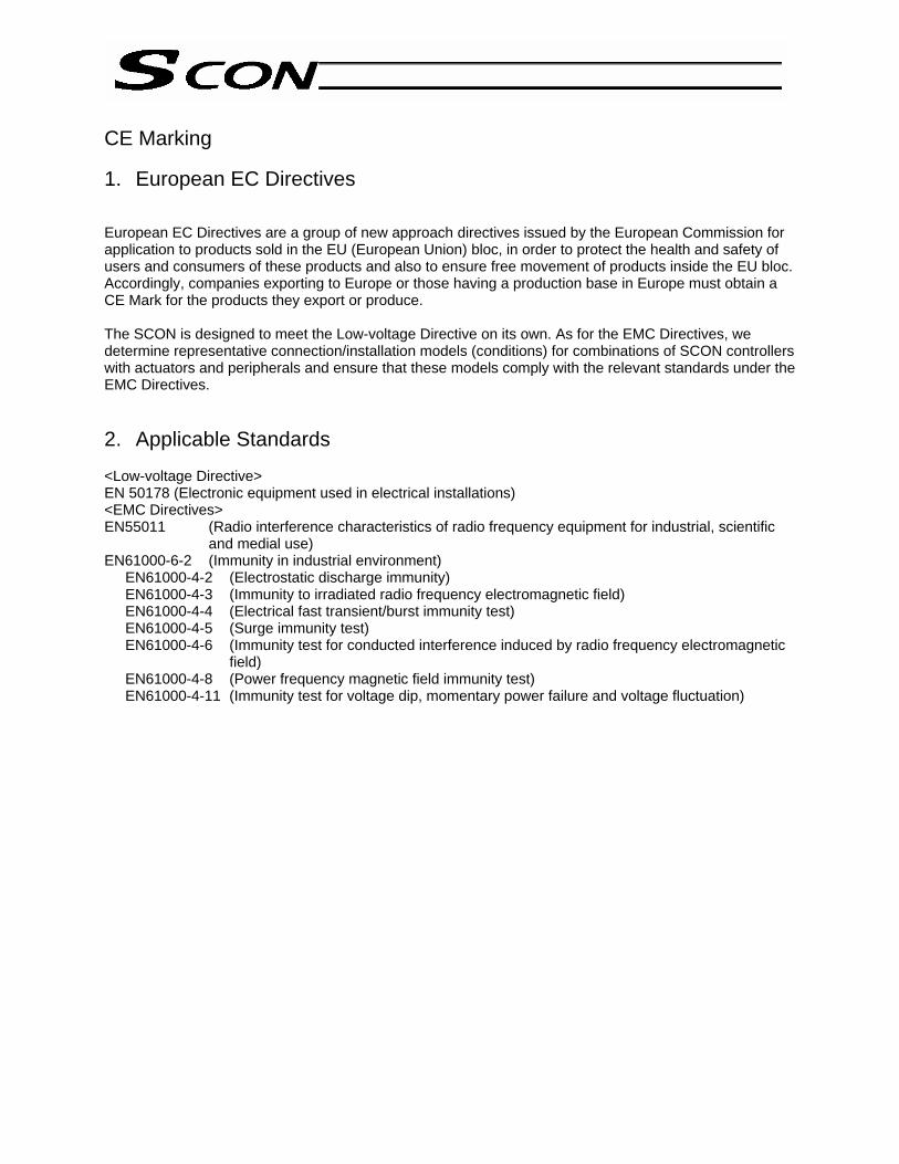
CE Marking 1. European EC Directives European EC Directives are a group of new approach directives issued by the European Commission for application to products sold in the EU (European Union) bloc, in order to protect the health and safety of users and consumers of these products and also to ensure free movement of products inside the EU bloc. Accordingly, companies exporting to Europe or those having a production base in Europe must obtain a CE Mark for the products they export or produce. The SCON is designed to meet the Low-voltage Directive on its own. As for the EMC Directives, we determine representative connection/installation models (conditions) for combinations of SCON controllers with actuators and peripherals and ensure that these models comply with the relevant standards under the EMC Directives. 2. Applicable Standards <Low-voltage Directive> EN 50178 (Electronic equipment used in electrical installations) <EMC Directives> EN55011 (Radio interference characteristics of radio frequency equipment for industrial, scientific
and medial use) EN61000-6-2 (Immunity in industrial environment)
EN61000-4-2 (Electrostatic discharge immunity) EN61000-4-3 (Immunity to irradiated radio frequency electromagnetic field) EN61000-4-4 (Electrical fast transient/burst immunity test) EN61000-4-5 (Surge immunity test) EN61000-4-6 (Immunity test for conducted interference induced by radio frequency electromagnetic
field) EN61000-4-8 (Power frequency magnetic field immunity test) EN61000-4-11 (Immunity test for voltage dip, momentary power failure and voltage fluctuation)

Use Environment
Item Standard Remarks Overvoltage category II Pollution degree II Protection level IP20 Protection class *1 I Altitude 2,000 m max.
*1) Protection class I equipment
Protection class I equipment incorporate an additional safety measure in the form of connection to a protective grounding conductor provided on the plant facility through fixed wiring to ensure safety against electric shock in a manner independent of basic insulation, so that any conductive part that may come in contact with the operator will not remain charged in the event of damage that results in loss of basic insulation. In short, protection class I equipment are equipment that must always be grounded.

3. Configuration of Peripherals (1) Environment
Use the SCON in an environment conforming to pollution degree 2 or 1 as specified in IEC 60664-1. Example) Installation in a control panel whose structure does not permit entry of water, oil, carbon,
dust, etc. (IP54). (2) Power supply
A) Use the SCON in an environment conforming to overvoltage category II as specified in IEC 60664-1. To this end, always install a circuit breaker between the distribution panel and the SCON controller.
B) When supplying power to the I/Os or electromagnetic brake externally, use a 24-VDC power supply whose input and output are protected by reinforced insulation (SELV) and bearing a CE Mark.
(3) Grounding
To prevent electric shock, always connect the protective grounding terminal on the SCON to the protective grounding point (grounding plate) on the control panel.
(4) Earth leakage detection breaker
Install a type BNote) earth leakage detection breaker (RCD) on the primary side of the SCON. Note) Type A: Capable of detecting alternating current and pulses / Type B: Capable of detecting
both alternating current and direct current
Encoder cable
Motor cable Actuator
100 or 200-VAC power supply bus
Control panel
Circuit breaker
Earth leakage detection breaker
Noise filter
Surge protector
Clamp filters
ControllerBrake
24-VDC power supply
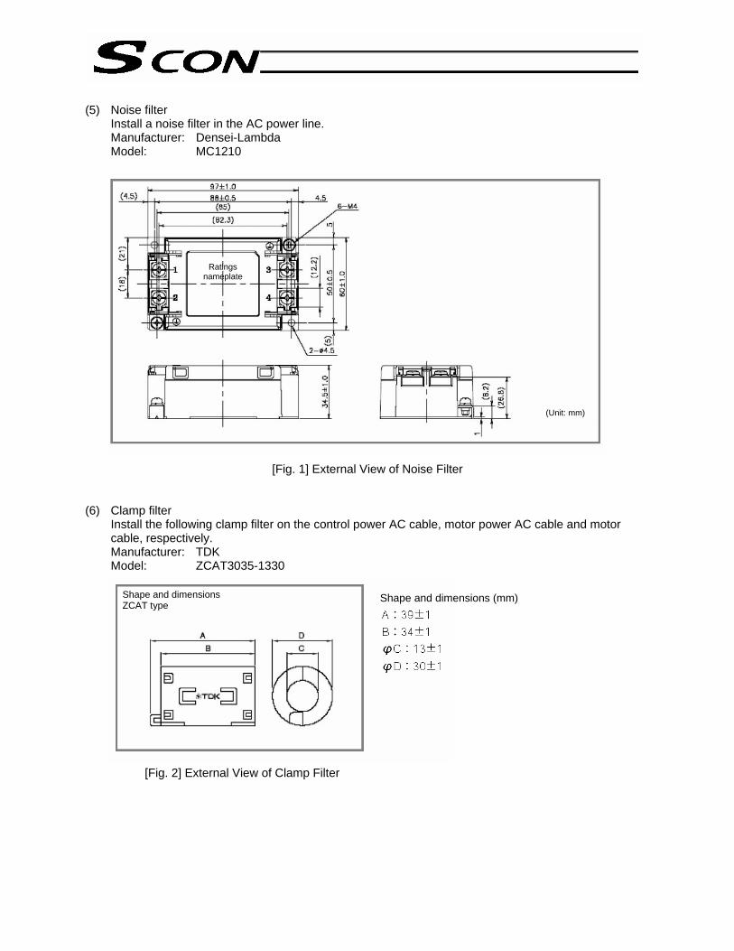
(5) Noise filter
Install a noise filter in the AC power line. Manufacturer: Densei-Lambda Model: MC1210
[Fig. 1] External View of Noise Filter (6) Clamp filter
Install the following clamp filter on the control power AC cable, motor power AC cable and motor cable, respectively. Manufacturer: TDK Model: ZCAT3035-1330
[Fig. 2] External View of Clamp Filter
Ratings nameplate
(Unit: mm)
Shape and dimensions ZCAT type Shape and dimensions (mm)

(7) Surge protector
Install a surge protector on the primary side of the noise filter. Manufacturer: Okaya Electric Industries Model: R-A-V-781BWZ-2A
[Fig. 3] External View of Surge Protector (8) Cable
Take note of the various limitations applicable to cables. A) All cables connected to the SCON, such as the motor cable, encoder cable and various network
cables, must have lengths not exceeding 30 m. B) Use a shielded two-core (single) twisted pair cable with a wire size of AWG16 to 24 for the brake
power cable, and ground its shield on the 24-VDC power supply side. C) If the controller is equipped with a CC-Link unit, use a 110-Ω CC-Link cable of version 1.10 and
install a clamp filter (ZCAT3035-1330) near the controller-end connector on the cable by looping the cable twice around the filter.
BWZ series

Table of Contents
Chapter 1 Introduction ................................................................................ 1
1. Overview ................................................................................................................... 1 1.1 Introduction................................................................................................................ 1 1.2 SCON Functions........................................................................................................ 1 1.3 How to Read the Model Specification........................................................................ 4 1.4 System Configuration ................................................................................................ 5 1.5 Procedure from Unpacking to Test Operation and Adjustment ................................. 6 1.6 Warranty Period and Scope of Warranty................................................................... 8
2. Specifications ............................................................................................................ 9 2.1 Basic Specifications................................................................................................... 9 2.2 Name and Function of Each Part .............................................................................11 2.3 External Dimensions................................................................................................ 22
3. Installation and Wiring ............................................................................................. 24 3.1 Installation Environment .......................................................................................... 24 3.2 Heat Radiation and Installation................................................................................ 24 3.3 Noise Elimination Measures and Grounding ........................................................... 25 3.4 Wiring the Power Supply ......................................................................................... 27 3.5 Connecting the Actuator .......................................................................................... 29 3.6 Connecting the PIO Cable (I/O) .............................................................................. 30 3.7 External Input/Output Specifications ....................................................................... 31 3.8 Connecting the Emergency Stop Input (Wiring to the System I/O Connector) ....... 33 3.9 Connecting the Regenerative Unit (RB) .................................................................. 40
Chapter 2 Positioner Mode ....................................................................... 42 1. I/O Signal Control and Signal Functions.................................................................. 42
1.1 PIO Patterns and Signal Assignments..................................................................... 42 1.2 Connecting the I/O Cable ........................................................................................ 51 1.3 Details of I/O Signal Functions ................................................................................ 57
2. Data Entry <Basics>................................................................................................ 67 2.1 Description of Position Table ................................................................................... 67 2.2 Explanation of Modes .............................................................................................. 74 2.3 Power-saving Modes at Standby Positions ............................................................. 84
3. Operation ................................................................................................................ 86 3.1 How to Start ............................................................................................................. 86 3.2 How Return Operation............................................................................................. 96 3.4 Push & Hold Mode................................................................................................. 100 3.5 Speed Change during Movement.......................................................................... 103 3.6 Operation at Different Acceleration and Deceleration Settings ............................. 105 3.7 Pause..................................................................................................................... 107 3.8 Zone Signal Output................................................................................................ 109 3.9 Incremental Moves .................................................................................................112 3.10 Jogging/Teaching Using PIO ..................................................................................118 3.11 Operation in 7-point Type ...................................................................................... 120 3.12 Operation in 3-point Type ...................................................................................... 124
Chapter 3 Pulse-train Input Mode ........................................................... 128
1. Overview ............................................................................................................... 128 1.1 Features................................................................................................................. 128 1.2 Standard Accessories ............................................................................................ 129 1.3 Options .................................................................................................................. 129
2. Wiring ............................................................................................................... 131 2.1 External Connection Diagram................................................................................ 131 2.2 Command Pulse-train Input Specifications............................................................ 132 2.3 Feedback Pulse Output Part ................................................................................. 133
3. I/O Signal Control and Signal Functions................................................................ 134 3.1 Input Signals.......................................................................................................... 134 3.2 Output Signals ....................................................................................................... 140
4. How to Switch to the Pulse-train Control Mode ..................................................... 144
5. Parameters............................................................................................................ 145 5.1 Parameter Settings Required for Operation .......................................................... 145 5.2 Effective Parameters in the Pulse-train Mode ....................................................... 149
* Appendix.................................................................................................................. 152
1. Actuator Specification List ..................................................................................... 152
2. Battery Backup Function ....................................................................................... 157 2.1 Absolute-encoder Backup Battery......................................................................... 158
3. Parameter Settings................................................................................................ 160 3.1 Parameter Table .................................................................................................... 160 3.2 Detail Explanation of Parameters .......................................................................... 162
4. PC/Teaching Pendant Connection Method in Multi-axis Configurations................ 180 4.1 Connection Example ............................................................................................. 180 4.2 Name and Function of Each Part of the SIO Converter ........................................ 181 4.3 Address Switch...................................................................................................... 183 4.4 Connection Cables ................................................................................................ 183 4.5 Detail Connection Diagram.................................................................................... 184
5. Troubleshooting..................................................................................................... 185 5.1 Action to Be Taken upon Occurrence of Problem ................................................. 185 5.2 Alarm Level Classification ..................................................................................... 186 5.3 Alarm Description Output Using PIO..................................................................... 187 5.4 Alarm Description and Cause/Action..................................................................... 189 5.5 Messages Displayed during Operation Using the Teaching Pendant ................... 198 5.6 Specific Problems .................................................................................................. 200 Recording of Parameters................................................................................................. 202


1
Chapter 1 Introduction
1. Overview 1.1 Introduction Thank you for purchasing the SCON controller. Please read this manual carefully to handle the controller with due care while ensuring the correct operation of the controller. Keep this manual with you so that you can reference the applicable sections whenever necessary. Should you encounter any trouble when actually starting up your system, also refer to the manuals for the teaching pendant, PC software and other components included in your system, in addition to this manual.
This manual does not cover all possible operations other than normal operations, or unexpected events such as complex signal changes resulting from use of critical timings. Accordingly, you should consider items not specifically explained in this manual as “prohibited.”
* We have made every effort to ensure accuracy of the information provided in this manual. Should you
find an error, however, or if you have any comment, please contact IAI. Keep this manual in a convenient place so it can be referenced readily when necessary. 1.2 SCON Functions The SCON is a single-axis AC servo controller capable of controlling actuators in the positioner mode or the pulse-train input mode. The functions of SCON are as follows: The positioner mode and the pulse-train input mode cannot be used at the same time. Switching of modes uses the piano switch located on the front face of the controller.
Positioner mode Pulse-train input mode
Standard type Teaching type 256-point positioning type 512-point positioning type 7-point type 3-point type

2
1.2.1 Features of the Positioner Mode In the positioner mode, one of five PIO patterns is selected using a parameter. The number of positioning points and input/output functions vary depending on the PIO pattern selected. The table below lists the parameter settings and corresponding PIO patterns, as well as the features of each PIO pattern.
Parameter setting Features of PIO pattern 0 Standard type
64 positioning points are supported. Available output functions include the moving output and zone output.
1 Teaching type 64 positioning points are supported. Normal positioning operation can be performed, along with jogging via I/O operation and writing of the current position to the position table. The MODE input signal is used to switch between the normal positioning operation mode and the teaching mode. The zone output (set by parameters) and brake forced-release input accessible in the standard type are not available in this type.
2 256-point positioning type The moving output and zone output (set by parameters) accessible in the standard type are not available in this type.
3 512-point positioning type The moving output and zone output (set by parameters/position data) accessible in the standard type are not available in this type.
4 7-point type Seven positioning points are supported. Direct command inputs and position complete outputs are provided separately for different target positions to simulate air-cylinder control. The moving output accessible in the standard type is not available in this type.
5 3-point type Three positioning points are supported. The function of position complete output signals is different from how these signals function in the 7-point type. The “position detection” function, which operates just like an auto-switch of an air cylinder, is also available.
3
1.2.2 Features of the Pulse-train Input Mode
Dedicated home return signal IAI’s original stroke-end push type home return operation is supported in this mode. When this function is used, home return can be performed automatically without having to program a complex sequence or use an external sensor, etc.
Brake control function
The electromagnetic brake power is supplied to the controller from a power supply different from the main power. Since the controller controls the brake, there is no need to program a separate sequence. Also, the electromagnetic brake can be released freely after the main power has been cut off.
Torque limiting function
The torque can be limited (a desired limit can be set by a parameter) using an external signal. When the torque reaches the specified level, a signal will be output. This function permits push & hold operation, press-fit operation, etc.
Feed-forward control function
With this function, response can be improved in certain situations such as when the load inertia ratio is high. Increasing the parameter value will reduce the deviation (difference between the position command and the position feedback), thereby improving response.
Position-command primary filter function
Soft start and stop can be achieved even when the actuator is operated in the command-pulse input mode where acceleration and deceleration are not considered.
Feedback function
Position detection data is output using pulse trains (differential). The current actuator position can be read in real time from the host controller.
4
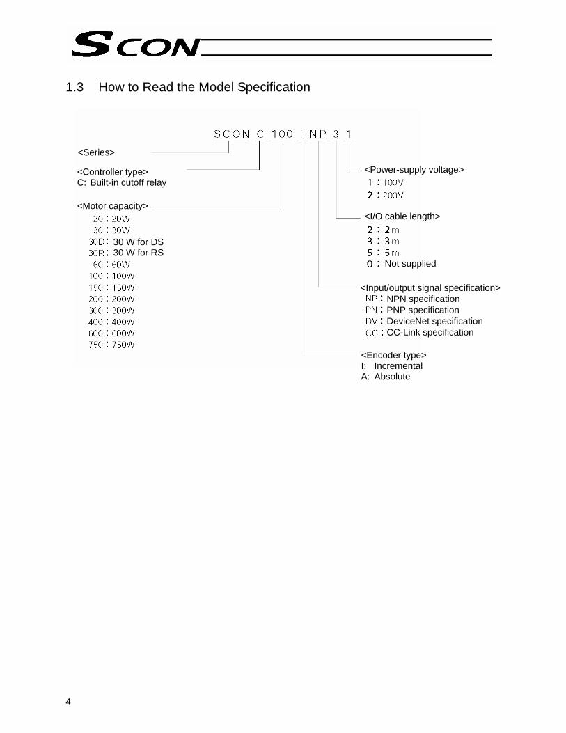
1.3 How to Read the Model Specification
<Series>
<Power-supply voltage> <Controller type> C: Built-in cutoff relay <Motor capacity>
30 W for DS 30 W for RS
<I/O cable length>
Not supplied
<Input/output signal specification> NPN specification PNP specification DeviceNet specification CC-Link specification
<Encoder type> I: Incremental A: Absolute
<Series>

5
1.4 System Configuration Note) The customer must provide a noise filter. A noise filter is always required at the minimum, even
when your system need not conform to the EC Directives. Also add clamp filters, etc., if necessary.
EMG switch
Regenerative resistance unit It may become necessary depending on the use condition.
Breaker Note) Noise filter
MC1210 by Densei-Lambda
Grounded
Teaching pendant
Host control system
Brake power supply
PC
Absolute battery
Actuator

6
1.5 Procedure from Unpacking to Test Operation and Adjustment If you are using this product for the first time, carry out each step by referring to the procedure below to ensure that all necessary items are checked and all wires are connected correctly. The procedure below covers the flow from unpacking to trial operation using a PC or teaching pendant. (1) Check the content in the package If you found any missing part or part specified for a different model, please contact your dealer. • Controller SCON-*- • Motor cable • Encoder cable • I/O flat cable • Pulse-train control connector plug • Pulse-train control connector housing • Pulse converter AK-04 (optional) • Actuator Options • Teaching pendant RCM-T RCM-E RCM-P • PC software RCM-101-MW, RCM-101-USB • Regenerative unit
• System I/O shorting connector • Power connector • Brake connector
(2) Installation [1] Affix the actuator. [2] Install the controller. (3) Wiring/connection • Connect the motor cable and encoder cable. • Wire the AC power supply. • Connect the grounding wire to ground. • Wire the emergency stop circuit. • Connect the I/O flat cable (wiring with the host PLC and 24-V I/O power supply). • Connect the 24-V brake power supply (only if the actuator is equipped with a brake). • Connect the regenerative unit(s). The need for regenerative unit will vary depending on the use
condition. (4) Turn on the power and check for alarms [1] If the SCON is to be used in the positioner mode, set piano switch 1 to the OFF position (right side). [2] Connect the PC or teaching pendant, and then set the AUTO/MANU switch to the MANU position. [3] Input the 24-V I/O power. [4] Input the AC power (control power, drive power).

7
If an emergency stop is actuated, the EMG LED indicator will illuminate in red. If an alarm generates, the ALM LED indicator will illuminate in orange. Check the nature of the alarm using the PC or teaching pendant and remove the cause by referring to Appendix 5, “Troubleshooting.” (5) Set parameters • Before the 24-V I/O power supply is connected, PIO power monitor can be disabled temporarily by
changing the applicable parameter setting. Parameter No. 51, “PIO power monitor”: 0 (Enable) → 1 (Disable) Note) After the 24-V I/O power supply has been connected, be sure to reset parameter No. 51 to “0”
to enable PIO power monitor. • If the host PLC or other host controller is not yet wired and the servo-on signal cannot be input, the
servo-on input can be disabled temporarily by changing the applicable parameter setting. Parameter No. 21, “Servo-on input”: 0 (Enable) → 1 (Disable) Note) After the host PLC, etc., has been wired, be sure to reset parameter No. 21 to “0” to enable the
servo-on input. Change the safety speed, if necessary. The factory-set safety speed is “100 mm/sec.” (If the maximum speed is less than 100 mm/sec, the safety speed conforms to the maximum speed.) • Select a desired PIO pattern using the applicable parameter.
Parameter No. 25, “PIO pattern selection”: 0 to 5 When a parameter has been changed, the new setting will become effective once the power is reconnected or software is reset. (6) Check the servo-on status When the servo turns on, the SV LED indicator will illuminate in green. (In the MANU teaching mode, the servo will not turn on even when the servo-on signal is input after the AC power has been turned on.) If the servo-on input is disabled by the parameter and the controller is in the AUTO mode, the servo will turn on automatically after the controller has started. (7) Operate with the PC or teaching pendant While the servo is on, perform the operation check specified below. For details on the operating method, refer to the operation manual for your PC software or teaching pendant. [1] Use the PC or teaching pendant to set a target position in the “Position” field of the position table. [2] Perform home return. [3] Move the actuator to the specified position. (8) Check the actuation of the emergency stop circuit While the actuator is operating, press the emergency stop button to confirm that an emergency stop will be actuated.

8
1.6 Warranty Period and Scope of Warranty The SCON controller you have purchased passed IAI’s shipping inspection implemented under the strictest standards. The unit is covered by the following warranty: 1. Warranty Period
The warranty period shall be one of the following periods, whichever ends first: • 18 months after shipment from our factory • 12 months after delivery to a specified location
2. Scope of Warranty
If an obvious manufacturing defect is found during the above period under an appropriate condition of use, IAI will repair the defect free of charge. Note, however, that the following items are excluded from the scope of warranty:
• Aging such as natural discoloration of coating • Wear of a consumable part due to use • Noise or other sensory deviation that doesn’t affect the mechanical function • Defect caused by inappropriate handling or use by the user • Defect caused by inappropriate or erroneous maintenance/inspection • Defect caused by use of a part other than IAI’s genuine part • Defect caused by an alteration or other change not approved by IAI or its agent • Defect caused by an act of God, accident, fire, etc.
The warranty covers only the product as it has been delivered and shall not cover any losses arising in connection with the delivered product. The defective product must be brought to our factory for repair.
Please read carefully the above conditions of warranty.

9
2. Specifications 2.1 Basic Specifications
Item SCON, less than 400 W SCON, 400 W or more Applicable motor capacity 20 to 399 [W] 400 to 750 [W] Power-supply voltage Single-phase 100 to 115 V ±
10% Single-phase 200 to 230 V ± 10%
Single-phase 200 to 230 V ± 10%
Power frequency 50/60 Hz ± 5% Standard input/output signal power 24 VDC ± 10%, 1 A (supplied externally) Electromagnetic brake power (when an actuator with brake is used)
24 VDC ± 10%, 1 A (peak) (supplied externally)
Momentary power failure resistance 0.5 cycle (not phase dependent) Motor control method Sine-wave PWM vector current control Supported encoders Incremental serial encoder
Absolute serial encoder ABZ (UVW) parallel encoder
Operation mode Positioner mode/pulser-train control mode (Operation modes are switched using a piano switch.)
Number of positions 512 points (maximum) Positioner mode Standard inputs/outputs 16 dedicated input points / 16 dedicated output points
(Selectable from 5 PIO patterns) Maximum input pulse frequency
500 kpps max. (differential) 200 kpps max. (open-collector)
Command pulse multiplier (electronic gear: A/B)
A, B = 1 to 4,096 1/50 < A/B < 50/1 (set by parameters)
Pulse-train control mode
Standard inputs/outputs 4 command input points / 6 feedback pulse output points (shielded PULSE connector) 8 dedicated input points / 12 dedicated output points (PIO connector)
Serial communication speed 9.6, 14.4, 19.2, 28.8, 38.4, 56.6, 76.8, 115.2, 230.4 kbps Data input method Teaching pendant, PC software Safety category Category B (built-in relay)
* Compliance with up to Category 1 can be achieved by externally connecting a safety relay, etc.
Protective functions Motor overvoltage, motor overcurrent, motor overload, driver temperature error, encoder error, etc.
Air cooling method Natural air cooling Forced air cooling Withstand voltage *1) Between primary and secondary sides: 1,500 VAC, 1 minute
Between primary side and FG: 1,500 VAC, 1 minute Insulation resistance Between secondary side and FG: 500 VDC, 100 MΩ or more

10
Item SCON, less than 400 W SCON, 400 W or more
Weight Approx. 800 g (absolute specification: + approx. 25 g)
Approx. 1,100 g (absolute specification: + approx. 25 g)
External dimensions 58 (W) x 194 (H) x 121 (D) (installation pitch: 184)
72 (W) x 194 (H) x 121 (D) (installation pitch: 184)
*1) The withstand voltage of the motor used in each actuator is 1,000 VAC for 1 minute. When
performing withstand voltage test on your system with the controller connected to the actuator, make sure a voltage exceeding 1,000 VAC will not be applied for more than 1 minute.

11
2.2 Name and Function of Each Part
[1] LED indicators
[2] Rotary switches
[3] Piano switches
[4] System I/O connector
[5] Regenerative unit connector
[6] Motor connector
[7] Power connector
[17] Grounding screw
[8] Dedicated pulse-train control connector
[9] PIO connector
[10] AUTO/MANU selector switch
[11] SIO connector
[12] Brake release switch
[13] Brake power connector
[14] Encoder/sensor connector
[15] Absolute battery connector
[16] Absolute battery holder

12
[1] LED indicators
These LEDs indicate the condition of the controller.
Name Color Description
PWR Green This LED illuminates when the system has become ready (after the power has been input and the CPU has started normally).
SV Green This LED illuminates when the servo has turned on. ALM Orange This LED illuminates while an alarm is present. EMG Red This LED illuminates while an emergency stop is actuated.
[2] Rotary switches
These switches are used to set the controller address. If two or more controllers are linked via serial communication, set a unique address for each controller. * The address set by the switches will become effective after the power is reconnected or software
is reset. [3] Piano switches
These switches are used to set the various modes of the controller system.
Name Description
1 Operation mode selector switch OFF: Positioner mode, ON: Pulse-train control mode * The mode set by the switch will become effective after the power is reconnected.
2
Remote update switch (normally set to the OFF position) OFF: Normal operation mode, ON: Update mode * The mode set by the switch will become effective after the power is reconnected or software
is reset. [4] System I/O connector
This connector is used to connect the emergency stop switch, etc. Connector: MC1.5/4-G-3.5 (Phoenix Contact) Applicable cable diameter: 0.2 to 1.3 mm2 (AWG24 to 16)
Pin No. Signal name Description
1 S1 Emergency-stop switch contact output for teaching pendant 2 S2 Emergency-stop switch contact output for teaching pendant 3 24V 24-V output 4 EMGIN Emergency sop input

13
[5] Regenerative unit connector
This connector is used to connect an external regenerative resistance unit. The need for regenerative unit will vary depending on the use condition.
[6] Motor connector
This connector is used to connect the motor power cable of the actuator.
Motor connector specifications Item Overview Description
Connector GIC2.5/4-STF-7.52 4-pin, 2-piece connector by Phoenix Contact Connector name M1 ~ 2 Motor connector
Cable size 0.75 mm2 (AWG18 or equivalent) Supplied with the actuator
Connected unit Actuator 1 PE Protective grounding wire 2 Out U Motor drive phase U 3 Out V Motor drive phase V
Terminal assignments
4 Out W Motor drive phase W [7] Power connector
This power connector accepts a 100/200-VAC single-phase power supply. The pins are divided into control power inputs and motor power inputs.
Item Specification Remarks Connector 6-pin, 2-piece connector MSTB2.5/6-STF-5.08
connector by Phoenix Contact Control power: 0.75 mm2
(AMG18) Applicable cable size Motor power: 2 mm2
(AMG14)
Recommended stripped wire length: 7 mm
Pin No. Signal name 1 L1 Motor power AC input 2 L2 Motor power AC input 3 L1C Control power AC input 4 L2C Control power AC input 5 NC Not connected
Terminal assignments
6 PE Grounding terminal Signal names are indicated on the mating connector.
[8] Dedicated pulse-train input mode connector
This connector is used when the controller is to be operated in the pulse-train input mode. Do not connect it if the controller is to be operated in the positioner mode.
[9] PIO connector
This connector is used to connect to the host controller (PLC, etc.) via the PIO (parallel input/output) cable. It consists of a 40-pin flat connector and constitutes a DIO group of 16 inputs and 16 outputs.

14
[10] AUTO/MANU switch
The operating mode using the teaching pendant/PC (software) connected to the SIO connector, and PIO input, will change as follows in accordance with the setting of this switch. Prohibition/permission of PIO activation is specified using the PC software/teaching pendant.
PIO activation inhibited
All operations are possible using the PC software/teaching pendant. PIO inputs are not accepted. MANU
PIO activation permitted
Only monitoring operations are possible using the PC software/teaching pendant. PIO inputs are accepted.
AUTO Only monitoring operations are possible using the PC software/teaching pendant. PIO inputs are accepted.
* The emergency stop switch on the teaching pendant is enabled when the switch is connected,
regardless of the AUTO/MANU mode. Take note that although an emergency stop is actuated momentarily when the teaching pendant or SIO cable is removed, this does not indicate an error condition.
[11] SIO connector
This connector is used to connect the dedicated communication cable for teaching pendant/PC. It is also used when two or more controllers are linked via serial communication.
[12] Brake release switch
This switch forcibly releases the electromagnetic brake of an actuator with brake. RLS: Power is supplied to the brake to forcibly release the brake. NOM: The controller controls ON/OFF of the brake. This setting should be used in normal conditions
of use. * A 24-VDC power supply must be connected to drive the brake.
[13] Brake power connector
This connector supplies the 24-VDC brake power. If an actuator with brake is connected, 24 VDC must be supplied externally.
[14] Encoder/sensor connector This connector is used to connect the encoder/sensor cables of the actuator. With the SCON, encoder voltage is adjusted using a parameter (one of four levels is set in
accordance with the encoder type and cable length).
15
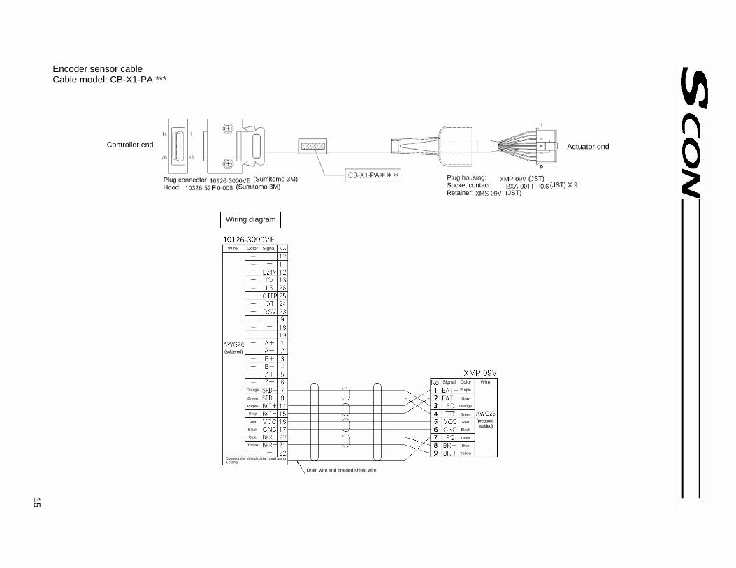
Encoder sensor cable Cable model: CB-X1-PA ***
Purple
Gray
Orange
Green
Red
Black
Drain
Blue
Yellow
Orange
Green
Purple
Gray
Red
Black
Blue
Yellow
Controller end
Plug connector: Hood:
(Sumitomo 3M)(Sumitomo 3M)
Actuator end
Plug housing:Socket contact:Retainer:
(JST)(JST) X 9
(JST)
Wiring diagram
Wire Color Signal
(soldered)
Connect the shield to the hood using a clamp.
Drain wire and braided shield wire
(pressure-welded)
Signal Color Wire

16 Cable model: CB-X1-PLA ***
White/Blue
White/Yellow
White/Red
White/Black
White/Purple
White/Gray
Orange
Green
Purple
Gray
Red
Black
Blue
Yellow
White/Blue
White/Yellow
White/Red
White/Black
White/Purple
White/Gray
Purple
Gray
Orange
Green
Red
Black Drain
Blue
Yellow
Controller end
Plug connector: Hood:
(Sumitomo 3M) (Sumitomo 3M)
Actuator end
Plug housing: Socket contact: Retainer:
(JST) X 9
LS side
(JST) X 6 Plug housing: Socket contact: Retainer:
(soldered)
Connect the shield to the hood using a clamp.
Drain wire and braided shield wire
(pressure-welded)
Signal Color Wire
Signal Color Wire
(pressure-welded)
Wiring diagram
Wire Color Signal
(JST)
(JST)
(JST)
Actuator end
LS side (JST)
17
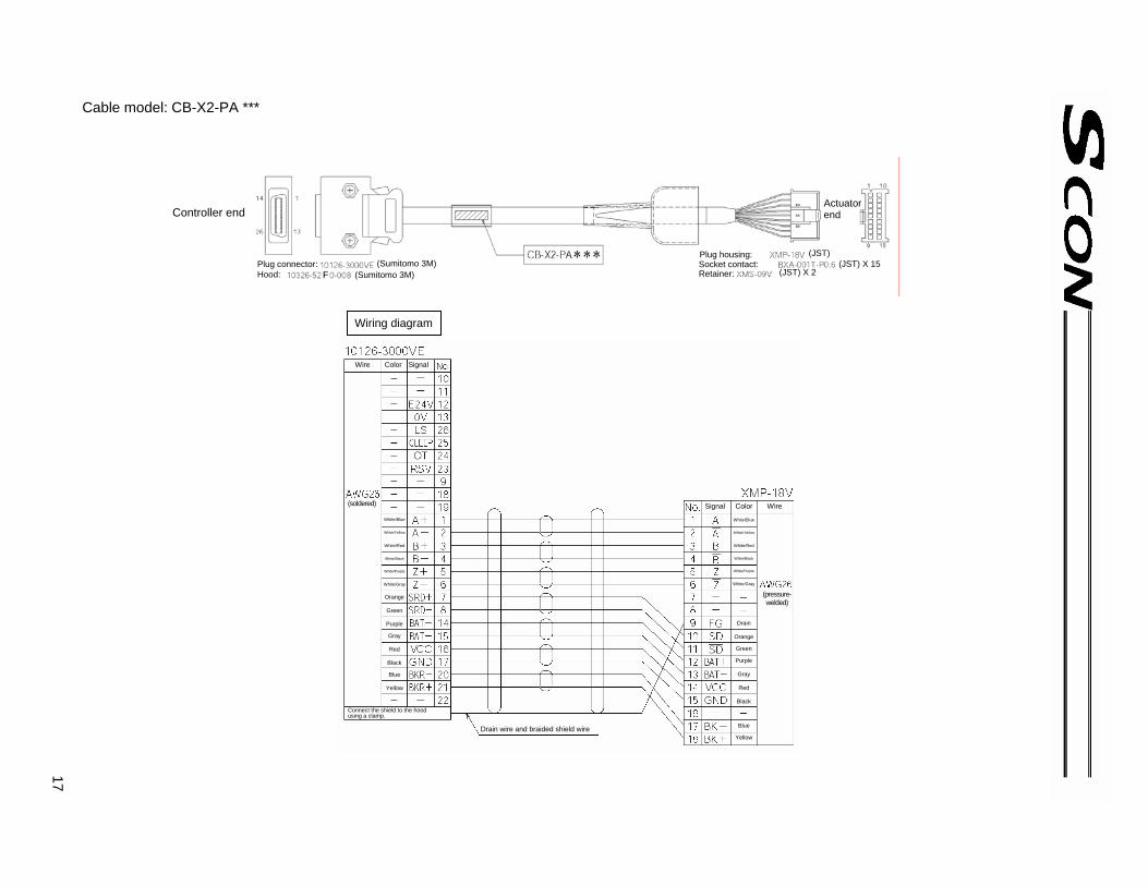
Cable model: CB-X2-PA ***
White/Blue
White/Yellow
White/Red
White/Black
White/Purple
White/Gray
Orange
Green
Purple
Gray
Red
Black
Blue
Yellow
White/Blue
White/Yellow
White/Red
White/Black
White/Purple
White/Gray
Drain
Orange Green Purple
Gray
Red
Black
Blue
Yellow
Controller end
Plug connector: Hood:
(Sumitomo 3M) (Sumitomo 3M)
Actuator end
Plug housing: Socket contact: Retainer:
(JST) X 15
(soldered)
Connect the shield to the hood using a clamp.
Drain wire and braided shield wire
(pressure-welded)
Signal Color Wire
Wiring diagram
Wire Color Signal
(JST) X 2
(JST)

18 Cable model: CB-X2-PLA ***
White/Orange
White/Green
Brown/Blue
Brown/Yellow
Brown/Red
Brown/Black
White/Blue
White/Yellow
White/Red
White/Black
White/Purple
White/Gray
Orange
Green
Purple
Gray
Red
Black
Blue
Yellow
White/Orange
White/Green
Brown/Blue
Brown/Yellow
Brown/Red
Brown/Black
White/Blue
White/Yellow
White/Red
White/Black
White/Purple
White/Gray
Drain Orange
Green
Purple
Gray
Red
Black
Blue
Yellow
Controller end
Plug connector: Hood:
(Sumitomo 3M) (Sumitomo 3M)
Actuator end
Plug housing: Socket contact: Retainer:
(JST) X 15
LS side
(JST) X 6 Plug housing: Socket contact: Retainer:
(soldered)
Connect the shield to the hood using a clamp.
Drain wire and braided shield wire
(pressure-welded)
Signal Color Wire
Signal Color Wire
(pressure-welded)
Wiring diagram
Wire Color Signal
(JST)
(JST)
Actuator end
LS side (JST) X 2
(JST)

19
Cable model: CB-RCS2-PA ***
White/Green
Brown/White
White/Blue
White/Yellow
White/Red
White/Black
White/Purple
White/Gray
Orange
Green
Purple
Gray
Red
Black
Blue
Yellow
Pink
Purple
White
Blue/Red
Orange/White
Green/White
Brown/White
Drain
Blue
Orange
Black
Yellow
Green
Brown
Gray/White
Gray
Red
Controller end
Plug connector: Hood:
(Sumitomo 3M) (Sumitomo 3M)
Actuator end
Plug housing: Socket contact: Retainer:
(JST) X 17 (JST) X 2
(soldered)
Connect the shield to the hood using a clamp.
Drain wire and braided shield wire
(pressure-welded)
Signal Color Wire
Wiring diagram
Wire Color Signal
(JST)

20 Cable model: CB-RCS2-PLA ***
Brown/White
Gray/White
Red/White
Black/White
Yellow/Black
Pink/Black
Pink
Purple
White
Blue/Red
Orange/White
Green/White
Blue
Orange
Black
Yellow
Green
Brown
Gray
Red
BrownWhite
Gray/White
Red/White
Black/White
Yellow/Black
Pnk/Black
Pink
Purple
White
Blue/Red
Orange/White
Green/White
Drain
Blue
Orange
Black
Yellow
Green
Brown
Gray
Red
Controller end
Plug connector: Hood:
(Sumitomo 3M) (Sumitomo 3M)
Actuator end
Plug housing: Socket contact: Retainer:
(JST) X 15
LS side
(JST) X 6 Plug housing: Socket contact: Retainer:
(soldered)
Connect the shield to the hood using a clamp.
Drain wire and braided shield wire
(pressure-welded)
Signal Color Wire
Signal Color Wire
(pressure-welded)
Wiring diagram
Wire Color Signal
(JST)
(JST)
Actuator end
LS side (JST) X 2
(JST)

21
[15] Absolute battery connector
This connector is used to connect the absolute-encoder backup battery (required when the controller is of absolute encoder specification).
[16] Absolute battery holder
This battery holder is used to install the absolute-encoder backup battery. [17] Grounding screw
This screw is used to implement protective grounding. It is connected inside the controller to the PE terminal in the power connector. Use this terminal if protective grounding based on a 2-piece connector is not feasible due to conflict with the safety standard or for any other reason.
Item Description
Cable size 2.0 to 5.5 mm2 or larger Grounding method Class D grounding

22
2.3 External Dimensions External dimensions of models with a power output of less than 400 W
When the absolute battery is installed (absolute encoder specification)

23
External dimensions of models with a power output of 400 W or more
When the absolute battery is installed (absolute encoder specification)
Fan

24
3. Installation and Wiring 3.1 Installation Environment (1) When installing and wiring the controller, do not block the ventilation holes for cooling. (Insufficient
ventilation may not only prevent the controller from demonstrating its design performance fully, but it may also cause a breakdown.)
(2) Prevent foreign matter from entering the controller through the ventilation holes. This controller is not dustproof or splashproof (against water or oil), so avoid using the controller in a place subject to large amounts of dust, oil mist or splashes of cutting fluid.
(3) Keep the controller from direct sunlight or irradiated heat from large heat sources such as heat treatment furnaces.
(4) Use the controller in an environment of 0 to 40°C in ambient temperature and 85% or below in humidity (non-condensing), where the ambient air is free from corrosive or flammable gases.
(5) Use the controller in an environment where it does not receive external vibration or impact. (6) Prevent electrical noise from entering the controller or connected cables. 3.2 Heat Radiation and Installation Design the control panel size, controller layout and cooling method so that the temperatures around the controller will always be kept to 40°C or below. Mount the controller on a wall vertically as shown below. This controller implements cooling by means of forced ventilation (air is blown out from the top). When installing the controller, observe the aforementioned direction and provide a minimum clearance of 100 mm above and 50 mm below the controller, and 30 mm from an adjacent controller. If you are installing multiple controllers side by side, provide a fan on top of the controllers to agitate the airflows as an effective way to keep the ambient temperatures constant. Provide a minimum clearance of 150 mm between the front face of the controller and the wall (cover). If multiple controllers are linked with the controllers arranged vertically, make sure the exhaust air from a given controller is not sucked into the controller above it. Provide a clearance of approx. 50 mm between a controller and a regenerative box, or 10 mm between regenerative boxes.
Air direction
At least 100 mm
At least 50 mm
At least 150 mm
Airflow Regenerative boxes
Fan

25
3.3 Noise Elimination Measures and Grounding The following explains the noise elimination measures that should be taken when using this controller. (1) Wiring and power connection [1] Provide dedicated class-D grounding using a grounding wire with a size of 2.0 to 5.5 mm2 or larger. [2] Cautions on wiring method
Separate the controller wiring from high-power lines of motive power circuits, etc. (Do not tie them together or place in the same cable duct.) If the supplied motor or encoder cable is to be extended, consult IAI’s Engineering Service Section or Sales Engineering Section.
(2) Noise sources and elimination Noise generates from many sources, but the most common sources of noise you should consider when designing a system are solenoid valves, magnet switches and relays. Noise generation from these components can be prevented by the method explained below. [1] AC solenoid valves, magnet switches, relays
Method --- Install a surge absorber in parallel with the coil
Point Connect to each coil over the shortest possible wiring distance. When a surge absorber is installed on the terminal block, etc., its noise elimination effect will decrease if the distance from the coil is long.
Controller Other equip- ment
Controller Other equip- ment
Connect a cable of the largest possible size over the shortest possible distance
Metal enclosure
Class-D grounding Good Avoid this pattern.

26
[2] DC solenoid valve/magnet switch relay
Action --- Install a diode in parallel with the coil. Determine the capacity of the diode in accordance with the load capacity.
In a DC circuit, connecting a diode in reverse polarities may damage the diode, internal controller parts, or DC power supply. Exercise due caution when connecting a diode.

27
3.4 Wiring the Power Supply 3.4.1 Connecting the Power Cable
As shown to the left, insert the stripped end of the cable into the connector and screw in the cable using a screwdriver. Recommended cable diameter Motor power (L1, L2): 2 mm (AWG14) Control power (L1C, L2C): 0.75 mm (AWG18) Recommended stripped wire length: 7 mm As shown to the left, tighten the screws to secure the connector.
Note) Always install a noise filter. Recommended noise filter: MC1210 by Densei-Lambda The power-supply voltage of the controller (100 or 200 V) has been set prior to the shipment.
28
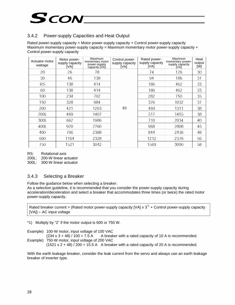
3.4.2 Power-supply Capacities and Heat Output Rated power-supply capacity = Motor power-supply capacity + Control power-supply capacity Maximum momentary power-supply capacity = Maximum momentary motor power-supply capacity + Control power-supply capacity RS: Rotational axis 200L: 200-W linear actuator 300L: 300-W linear actuator 3.4.3 Selecting a Breaker Follow the guidance below when selecting a breaker. As a selection guideline, it is recommended that you consider the power-supply capacity during acceleration/deceleration and select a breaker that accommodates three times (or twice) the rated motor power-supply capacity. Rated breaker current > (Rated motor power-supply capacity [VA] x 3*1 + Control power-supply capacity [VA]) ÷ AC input voltage
*1) Multiply by “2” if the motor output is 600 or 750 W. Example) 100-W motor, input voltage of 100 VAC
(234 x 3 + 48) / 100 = 7.5 A A breaker with a rated capacity of 10 A is recommended. Example) 750-W motor, input voltage of 200 VAC
(1521 x 2 + 48) / 200 = 15.5 A A breaker with a rated capacity of 20 A is recommended. With the earth leakage breaker, consider the leak current from the servo and always use an earth leakage breaker of inverter type.
Actuator motor wattage
Motor power-supply capacity
[VA]
Maximum momentary motor
power-supply capacity [VA]
Control power-supply capacity
[VA]
Rated power-supply capacity
[VA]
Maximum momentary power-
supply capacity [VA]
Heat output
[W]

29
3.5 Connecting the Actuator 3.5.1 Connecting the Motor Cable (MOT1, 2)
Connect the motor cable of the actuator to the motor connector on the front face of the controller. Use a screwdriver to tighten the screws at the top and bottom of the connector to secure the connector.
2. 3.5.2 Connecting the Encoder Cable (PG1, PG2)
Connect the encoder cable of the actuator to the encoder connector on the front face of the controller. Note) If the controller is of absolute specification, disconnect
the absolute battery connector before connecting the encoder cable.
30
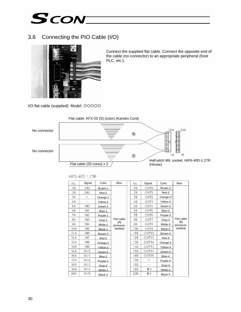
3.6 Connecting the PIO Cable (I/O)
Connect the supplied flat cable. Connect the opposite end of the cable (no connector) to an appropriate peripheral (host PLC, etc.).
I/O flat cable (supplied) Model:
Flat cable: KFX-20 (S) (color) (Kaneko Cord)
No connector No connector
Flat cable (20 cores) x 2Half-pitch MIL socket: HIF6-40D-1.27R (Hirose)
Brown-1 Red-1
Orange-1 Yellow-1 Green-1 Blue-1
Purple-1 Gray-1 White-1 Black-1 Brown-2 Red-2
Orange-2 Yellow-2 Green-2 Blue-2
Purple-2 Gray-2 White-2 Black-2
Brown-3 Red-3
Orange-3 Yellow-3 Green-3 Blue-3
Purple-3 Gray-3 White-3 Black-3 Brown-4 Red-4
Orange-4 Yellow-4 Green-4 Blue-4
Purple-4 Gray-4 White-4 Black-4
Signal Color Wire Signal Color Wire
Flat cable [A]
(pressure-welded)
Flat cable [B]
(pressure-welded)

31
3.7 External Input/Output Specifications The standard interface specification of the controller is NPN, but the PNP specification is also available as an option. To prevent confusion during wiring, the NPN and PNP specifications use the same power line configuration. Accordingly, there is no need to reverse the power signal assignments for a PNP controller. 3.7.1 External Input Specifications
Item Specification Number of input points 16 points
Input voltage 24 VDC ± 10% Input current 4 mA/point
ON voltage: Min. 18 VDC (3.5 mA) ON/OFF voltage OFF voltage: Max. 6 VDC (1 mA)
Insulation method Photocoupler Internal circuit configuration
[NPN specification]
[PNP specification]
Each input
Each input
Internal circuit
Internal circuit
Each input
Each input
Logic circuit
Logic circuit

32
Internal circuit
Each output Load
Load
Internal circuit
Each output
Load
Load
Each output
Each output
3.7.2 External Output Specifications
Item Specification Number of output points 16 points
Rated load voltage 24 VDC Maximum current 100 mA/point 400 mA/8 points Insulation method Photocoupler
Internal circuit configuration
[NPN specification]
[PNP specification]
Logic circuit
Logic circuit

33
3.8 Connecting the Emergency Stop Input (Wiring to the System I/O
Connector)
As shown to the left, insert the stripped end of the cable while pressing down the spring using a screwdriver. Applicable cable diameter: 0.2 to 1.3 mm (AWG24 to 16) Recommended stripped wire length: 10 mm
Emergency stop switch

34
Emergency stop circuit when multiple controllers are linked Internal drive-source cutoff specification (Safety category B) The emergency stop switch on the teaching pendant is effective only with respect to the controller to which the teaching pendant is connected. Connect an emergency-stop status relay for each controller. Be sure to install a surge-absorbing element for the external relay. S1, S2 contact specification: 30 VDC/0.5 A
SIO connector
Main EMG switch
System I/O connector
Power connector Motor power
EMG line control relayTP connected: Open TP not connected: Closed
EMG line control relayTP connected: Open TP not connected: Closed
EMG line control relayTP connected: Open TP not connected: Closed
SIO connector
SIO connector
System I/O connector
System I/O connector
Power connector
Power connector Motor power Motor power

35
Internal drive-source cutoff specification (Safety category B) The emergency stop switch on the teaching pendant is effective with respect to all controllers connected. Connect the main emergency stop switch in series with the teaching-pendant emergency stop line for each controller. Connect an emergency-stop status relay for each controller. Be sure to install a surge-absorbing element for the external relay. S1, S2 contact specification: 30 VDC/0.5 A
SIO connector
Main EMG switch
System I/O connector
Power connector Motor power
EMG line control relayTP connected: Open TP not connected: Closed
EMG line control relayTP connected: Open TP not connected: Closed
EMG line control relayTP connected: Open TP not connected: Closed
SIO connector
SIO connector
System I/O connector
System I/O connector
Power connector
Power connectorMotor power Motor power
36
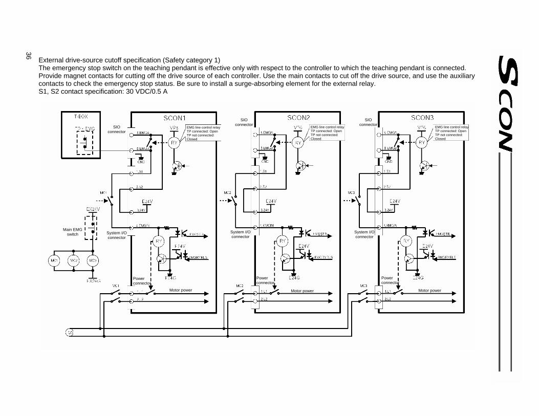
External drive-source cutoff specification (Safety category 1) The emergency stop switch on the teaching pendant is effective only with respect to the controller to which the teaching pendant is connected. Provide magnet contacts for cutting off the drive source of each controller. Use the main contacts to cut off the drive source, and use the auxiliary contacts to check the emergency stop status. Be sure to install a surge-absorbing element for the external relay. S1, S2 contact specification: 30 VDC/0.5 A
SIO connector
Main EMG switch System I/O
connector
Power connector
Motor power
EMG line control relayTP connected: Open TP not connected: Closed
EMG line control relayTP connected: Open TP not connected: Closed
EMG line control relayTP connected: Open TP not connected: Closed
SIO connector
SIO connector
System I/O connector
System I/O connector
Power connector
Power connector
Motor power Motor power

37
External drive-source cutoff specification (Safety category 1) The emergency stop switch on the teaching pendant is effective with respect to all controllers connected. Connect the main emergency stop switch in series with the teaching-pendant emergency stop line for each controller. Provide magnet contacts for cutting off the drive source. Use the main contacts to cut off the drive source, and use the auxiliary contacts to check the emergency stop status. Be sure to install a surge-absorbing element for the external relay. S1, S2 contact specification: 30 VDC/0.5 A
SIO connector
Main EMG switch
System I/O connector
Power connector
Motor power
EMG line control relayTP connected: Open TP not connected: Closed
EMG line control relayTP connected: Open TP not connected: Closed
EMG line control relayTP connected: Open TP not connected: Closed
SIO connector
SIO connector
System I/O connector
System I/O connector
Power connector
Power connector
Motor power Motor power

38
Connecting the Pulse-train Control Cable
Use the pulse-train control cable when the controller is operated in the pulse-train input mode. It should not be connected when the controller is operated in the positioner mode. The pulse-train control cable is optional. (Normally the controller comes only with a plug and a shell.)
Connecting the Brake Power Input (for Actuator with Brake)
As shown to the left, insert the stripped end of the cable into the connector and screw in the cable using a screwdriver. Applicable cable: 0.75 to 1.25 mm Recommended stripped wire length: 7 mm
24 VDC ± 10%, 1 A max.

39
Connecting the Teaching Pendant/PC Software (TP) (Optional)
If the teaching pendant/PC software cable is used, connect it to the teaching connector on the controller. Set the AUTO/MANU selector switch to the MANU position (right side).

40
3.9 Connecting the Regenerative Unit (RB) Regenerative energy produced when the actuator decelerates to a stop or moves downward in vertical installation is absorbed by means of the capacitor or resistor provided in the controller. If the produced regenerative energy cannot be fully absorbed by the controller, an overheat error (error code: 0CA) will generate. If this is the case, connect one or more regenerative resistance units externally. 3.9.1 Number of Units to Be Connected Guideline for number of units to be connected
Motor wattage Horizontal installation Vertical installation
Number of regenerative resistance units to be connected
~ 200W ~ 100W Not required 300 ~ 750W 150 ~ 400W 1
- 600 ~ 750W 2 * The reference figures shown above assume that the actuator is operated back and forth over a 1,000-
mm stroke at 3,000 rpm, 0.3 G, rated load, and operating duty of 50%. * If the operating duty exceeds 50%, the applicable number of regenerative units shown in the table
above must be increased. The maximum number of external regenerative resistance units that can be connected is as follows: Less than 400 W --- 2 units 400 W or more --- 4 units (Never connect external regenerative resistance units more than the limits shown above, as it may result in system failures.)
3.9.2 Connection Method The figure below illustrates how one regenerative unit, and multiple units, should be connected, respectively. When connecting one regenerative unit, connect the unit using cable [1] explained in 3.9.3. When connecting two or more regenerative units, connect the controller with the first regenerative unit using cable [1], and connect the adjacent regenerative units using cable [2].
[1]
[2] [2] [1]

41
3.9.3 Connection Cables The cable used to connect the controller to a regenerative resistance unit is different from the corresponding cable used on conventional controllers (the connectors are not compatible). To connect a regenerative resistance unit to the controller, cable [1] specified below is required. [1] Regenerative resistance connection cable for SCON (CB-SC-REU***) [2] Regenerative resistance connection cable for conventional controllers (X-SEL, E-Con) (CB-ST-
REU***)
Controller end
Wiring diagram
Wire Color Signal Signal Color Wire Light blue
Brown
Green/Yellow
Wire Color Signal Signal Color Wire
Receptacle housing: Receptacle contact:
Sales model nameplate
External regenerative resistance unit end
External regenerative resistance unit end
Plug: (Phoenix Contact)
Light blue
Brown
Green/Yellow
Light blue
Brown
Green/Yellow
Light blue
Brown
Green/Yellow
Plug: (Phoenix Contact)
Plug: (Phoenix Contact)
Sales model nameplate
Controller end
Wiring diagram

42
Chapter 2 Positioner Mode
1. I/O Signal Control and Signal Functions 1.1 PIO Patterns and Signal Assignments This controller provides six PIO pattern types to meet the needs of various applications. To select a desired type, set a corresponding value from 0 to 5 in parameter No. 25 (PIO pattern selection). The features of each PIO pattern are explained below: Parameter No.
25 setting Feature of PIO pattern
0 Standard type A basic type supporting 64 positioning points and two zone outputs. * How to set zone boundaries within which to output a zone signal: Zone boundaries are set using parameter Nos. 1 and 2 for one zone output, and in the position table for another zone output.
1 Teaching type In this type, 64 positioning points and one zone output (boundaries are set in the position table) are supported. In addition to the normal positioning mode, the user can also select the teaching mode in which the actuator can be jogged via I/Os and the current actuator position can be written to a specified position. (Note) Positions can be rewritten by approximately 100,000 times.
2 256-point positioning type The number of positioning points is increased to 256, so only one zone output is available (boundaries are set in the position table).
3 512-point positioning type The number of positioning points is increased to 512, so no zone output is available.
4 7-point type The number of positioning points is limited to seven, but separate direct command inputs and position complete outputs are provided. PLC ladder sequence circuits can be designed easily.
5 3-point type Use of the controller as an air cylinder is assumed in this type. The function of position complete output signals is different from how these signals function in the 7-point type. These signals not only indicate that the position specified by each move command “has been reached,” but the also function as a limit switch. This means that the signals will turn ON even when the actuator is moved by hand.

43
Quick reference table for functions available under each PIO pattern ( : Available, X: Not available)
No. 25 Number of positioning points
Zone output Boundaries set by parameters
Zone output Boundaries set in the position table
Brake release input signal
(BKRL)
Moving output signal (MOVE)
0 64 points 1 64 points x x 2 256 points x x 3 512 points x x x 4 7 points x 5 3 points x

44
1.1.1 Explanation of Signal Names The following explains the signal names, and gives a function overview of each signal. In the explanation of operation timings provided in a later section, each signal is referenced by its self-explanatory name for clarity. If necessary, however, such as when marker tubes are inserted as a termination of the flat cable, use the signal abbreviations.
PIO pattern = 0 [Standard type] Category Signal name Signal
abbreviation Function overview
PC1 PC2 PC4 PC8 PC16
Command position number
PC32
The target position number is input. A command position number must be specified by 6 ms before the start signal (CSTR) turns ON.
Brake release BKRL This signal is used on an actuator equipped with a brake to forcibly release the brake.
Operating mode RMDO This signal switches the operating mode between AUTO and MANU.
Home return HOME Home return operation is started at a rise edge of this signal.
*Pause *STP ON: Actuator can be moved, OFF: Actuator decelerates to a stop
Start CSTR The actuator will start moving at a rise edge of this signal. Alarm reset RES An alarm is reset at a rise edge of this signal.
Input
Servo ON SON The servo remains ON while this signal is ON. The servo remains OFF while this signal is OFF.
PM1 PM2 PM4 PM8 PM16
Completed position number
PM32
The relevant position number is output when positioning has completed. The signal will turn OFF when the next start signal is received. It is used by the PLC to check if the commanded position has definitively been reached, and also to provide a position interlock, etc.
Moving MOVE
This signal will remain ON while the actuator is moving, and OFF while the actuator is standing still. Used to check the operation or determine if the load was missed in push & hold operation.
Zone 1 ZONE1 This signal becomes effective after home return. It will turn ON when the current actuator position enters the range set by the parameters and remain ON until the actuator exits the range.
Position zone PZONE
This signal becomes effective after a position movement command is input. It will turn ON when the current actuator position enters the range specified in the position table and remain ON until the actuator exits the range.
Operating mode status RMDS A signal indicating the operating mode of AUTO or MANU is output.
Home return completion HEND This signal is OFF immediately after the power is input, and turns ON when home return has completed.
Position complete PEND This signal turns ON when the target position was reached and the actuator has entered the specified in-position range. It is used to determine whether positioning has completed.
Servo-on status SV This signal is always output once the servo is turned ON and the controller is ready to operate.
*Emergency stop *EMGS When this signal is OFF, it means that an emergency stop is being actuated.
*Alarm *ALM This signal remains ON in normal conditions of use and turns OFF when an alarm generates.
Output
*Battery alarm *BALM This signal is ON when the absolute battery voltage is normal or an incremental encoder is used.

45
PIO pattern = 1 [Teaching type] Category Signal name Signal
abbreviation Function overview
PC1 PC2 PC4 PC8 PC16
Command position number
PC32
The target position number is input. A command position number must be specified by 6 ms before the start signal (CSTR) turns ON.
Operation mode MODE Mode selection (ON: Teaching mode, OFF: Normal mode) Jog/inching switching JISL OFF: Jog, ON: Inching
+jog/inching movement JOG+ The actuator will start jogging or inching in the positive direction at an ON edge of this signal.
-jog/inching movement JOG- The actuator will start jogging or inching in the negative direction at an ON edge of this signal.
Operating mode RMDO This signal switches the operating mode between AUTO and MANU.
Home return HOME Home return operation is started at a rise edge of this signal.
*Pause *STP ON: Actuator can be moved, OFF: Actuator decelerates to a stop
Start CSTR The actuator will start moving at a rise edge of this signal.
Current-position write PWRT When this signal has remained ON for 20 msec or longer, the current position will be stored under the position number selected by PC1 to PC32.
Alarm reset RES An alarm is reset at a rise edge of this signal.
Input
Servo ON SON The servo remains ON while this signal is ON. The servo remains OFF while this signal is OFF.
PM1 PM2 PM4 PM8 PM16
Completed position number
PM32
The relevant position number is output when positioning has completed. The signal will turn OFF when the next start signal is received.It is used by the PLC to check if the commanded position has definitively been reached, and also to provide a position interlock, etc.
Moving MOVE
This signal will remain ON while the actuator is moving, and OFF while the actuator is standing still. Used to check the operation or determine if the load was missed in push & hold operation.
Mode status MODES ON: Teaching mode, OFF: Normal mode
Position zone PZONE
This signal becomes effective after a position movement command is input. It will turn ON when the current actuator position enters the range specified in the position table and remain ON until the actuator exits the range.
Operating mode status RMDS A signal indicating the operating mode of AUTO or MANU is output.
Home return completion HEND This signal is OFF immediately after the power is input, and
turns ON when home return has completed.
Position complete PEND This signal turns ON when the target position was reached and the actuator has entered the specified in-position range. It is used to determine whether positioning has completed.
Write completion WEND This signal is output upon completion of writing to the nonvolatile memory in response to a current-position write command (PWRT).
Servo-on status SV This signal is always output once the servo is turned ON and the controller is ready to operate.
*Emergency stop *EMGS OFF: Emergency stop has been actuated
*Alarm *ALM This signal remains ON in normal conditions of use and turns OFF when an alarm generates.
Output
*Battery alarm *BALM This signal is ON when the absolute battery voltage is normal or an incremental encoder is used.

46
PIO pattern = 2 [256-point type] Category Signal name Signal
abbreviation Function overview
PC1 PC2 PC4 PC8 PC16 PC32 PC64
Command position number
PC128
The target position number is input. A command position number must be specified by 6 ms before the start signal (CSTR) turns ON.
Brake release BKRL This signal is used on an actuator equipped with a brake to forcibly release the brake.
Operating mode RMDO This signal switches the operating mode between AUTO and MANU.
Home return HOME Home return operation is started at a rise edge of this signal.
*Pause *STP ON: Actuator can be moved, OFF: Actuator decelerates to a stop
Start CSTR The actuator will start moving at a rise edge of this signal. Alarm reset RES An alarm is reset at a rise edge of this signal.
Input
Servo ON SON The servo remains ON while this signal is ON. The servo remains OFF while this signal is OFF.
PM1 PM2 PM4 PM8 PM16 PM32 PM64
Completed position number
PM128
The relevant position number is output when positioning has completed. The signal will turn OFF when the next start signal is received.It is used by the PLC to check if the commanded position has definitively been reached, and also to provide a position interlock, etc.
Position zone PZONE
This signal becomes effective after a position movement command is input. It will turn ON when the current actuator position enters the range specified in the position table and remain ON until the actuator exits the range.
Operating mode status RMDS A signal indicating the operating mode of AUTO or MANU is output.
Home return completion HEND This signal is OFF immediately after the power is input, and
turns ON when home return has completed.
Position complete PEND This signal turns ON when the target position was reached and the actuator has entered the specified in-position range. It is used to determine whether positioning has completed.
Servo-on status SV This signal is always output once the servo is turned ON and the controller is ready to operate.
*Emergency stop *EMGS OFF: Emergency stop has been actuated
*Alarm *ALM This signal remains ON in normal conditions of use and turns OFF when an alarm generates.
Output
*Battery alarm *BALM This signal is ON when the absolute battery voltage is normal or an incremental encoder is used.

47
PIO pattern = 3 [512-point type] Category Signal name Signal
abbreviation Function overview
PC1 PC2 PC4 PC8 PC16 PC32 PC64 PC128
Command position number
PC256
The target position number is input. A command position number must be specified by 6 ms before the start signal (CSTR) turns ON.
Brake release BKRL This signal is used on an actuator equipped with a brake to forcibly release the brake.
Operating mode RMDO This signal switches the operating mode between AUTO and MANU.
Home return HOME Home return operation is started at a rise edge of this signal.
*Pause *STP ON: Actuator can be moved, OFF: Actuator decelerates to a stop
Start CSTR The actuator will start moving at a rise edge of this signal. Alarm reset RES An alarm is reset at a rise edge of this signal.
Input
Servo ON SON The servo remains ON while this signal is ON. The servo remains OFF while this signal is OFF.
PM1 PM2 PM4 PM8 PM16 PM32 PM64 PM128
Completed position number
PC256
The relevant position number is output when positioning has completed. The signal will turn OFF when the next start signal is received.It is used by the PLC to check if the commanded position has definitively been reached, and also to provide a position interlock, etc.
Operating mode status RMDS A signal indicating the operating mode of AUTO or MANU is output.
Home return completion HEND This signal is OFF immediately after the power is input, and
turns ON when home return has completed.
Position complete PEND This signal turns ON when the target position was reached and the actuator has entered the specified in-position range. It is used to determine whether positioning has completed.
Servo-on status SV This signal is always output once the servo is turned ON and the controller is ready to operate.
*Emergency stop *EMGS OFF: Emergency stop has been actuated
*Alarm *ALM This signal remains ON in normal conditions of use and turns OFF when an alarm generates.
Output
*Battery alarm *BALM This signal is ON when the absolute battery voltage is normal or an incremental encoder is used.
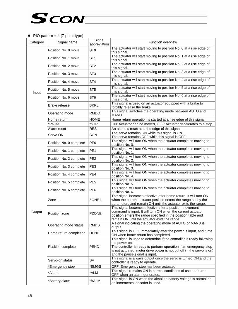
48
PIO pattern = 4 [7-point type] Category Signal name Signal
abbreviation Function overview
Position No. 0 move ST0 The actuator will start moving to position No. 0 at a rise edge of this signal.
Position No. 1 move ST1 The actuator will start moving to position No. 1 at a rise edge of this signal.
Position No. 2 move ST2 The actuator will start moving to position No. 2 at a rise edge of this signal.
Position No. 3 move ST3 The actuator will start moving to position No. 3 at a rise edge of this signal.
Position No. 4 move ST4 The actuator will start moving to position No. 4 at a rise edge of this signal.
Position No. 5 move ST5 The actuator will start moving to position No. 5 at a rise edge of this signal.
Position No. 6 move ST6 The actuator will start moving to position No. 6 at a rise edge of this signal.
Brake release BKRL This signal is used on an actuator equipped with a brake to forcibly release the brake.
Operating mode RMDO This signal switches the operating mode between AUTO and MANU.
Home return HOME Home return operation is started at a rise edge of this signal. *Pause *STP ON: Actuator can be moved, OFF: Actuator decelerates to a stop Alarm reset RES An alarm is reset at a rise edge of this signal.
Input
Servo ON SON The servo remains ON while this signal is ON. The servo remains OFF while this signal is OFF.
Position No. 0 complete PE0 This signal will turn ON when the actuator completes moving to position No. 0.
Position No. 1 complete PE1 This signal will turn ON when the actuator completes moving to position No. 1.
Position No. 2 complete PE2 This signal will turn ON when the actuator completes moving to position No. 2.
Position No. 3 complete PE3 This signal will turn ON when the actuator completes moving to position No. 3.
Position No. 4 complete PE4 This signal will turn ON when the actuator completes moving to position No. 4.
Position No. 5 complete PE5 This signal will turn ON when the actuator completes moving to position No. 5.
Position No. 6 complete PE6 This signal will turn ON when the actuator completes moving to position No. 6.
Zone 1 ZONE1 This signal becomes effective after home return. It will turn ON when the current actuator position enters the range set by the parameters and remain ON until the actuator exits the range.
Position zone PZONE This signal becomes effective after a position movement command is input. It will turn ON when the current actuator position enters the range specified in the position table and remain ON until the actuator exits the range.
Operating mode status RMDS A signal indicating the operating mode of AUTO or MANU is output.
Home return completion HEND This signal is OFF immediately after the power is input, and turns ON when home return has completed.
Position complete PEND
This signal is used to determine if the controller is ready following the power on. The controller is ready to perform operation if an emergency stop is not actuated, motor drive power is not cut off (= the servo is on) and the pause signal is input.
Servo-on status SV This signal is always output once the servo is turned ON and the controller is ready to operate.
*Emergency stop *EMGS OFF: Emergency stop has been actuated
*Alarm *ALM This signal remains ON in normal conditions of use and turns OFF when an alarm generates.
Output
*Battery alarm *BALM This signal is ON when the absolute battery voltage is normal or an incremental encoder is used.

49
PIO pattern = 5 [3-point type] Category Signal name Signal
abbreviation Function overview
Rear end move command ST0 The actuator will move toward the rear end while this signal
remains at ON level. Front end move command ST1 The actuator will move toward the front end while this signal
remains at ON level. Intermediate point move command ST2 The actuator will move toward the intermediate point while this
signal remains at ON level.
Brake release BKRL This signal is used on an actuator equipped with a brake to forcibly release the brake.
Operating mode RMDO This signal switches the operating mode between AUTO and MANU.
Alarm reset RES An alarm is reset at a rise edge of this signal.
Input
Servo ON SON The servo remains ON while this signal is ON. The servo remains OFF while this signal is OFF.
Rear end move command
LS0 This signal will remain ON while the rear end is recognized.
Front end move command
LS1 This signal will remain ON while the front end is recognized.
Intermediate point move command
LS2 This signal will remain ON while the intermediate point is recognized.
Zone 1 ZONE1 This signal becomes effective after home return. It will turn ON when the current actuator position enters the range set by the parameters and remain ON until the actuator exits the range.
Position zone PZONE
This signal becomes effective after a position movement command is input. It will turn ON when the current actuator position enters the range specified in the position table and remain ON until the actuator exits the range.
Operating mode status RMDS A signal indicating the operating mode of AUTO or MANU is output.
Home return completion HEND This signal is OFF immediately after the power is input, and
turns ON when home return has completed.
Servo-on status SV This signal is always output once the servo is turned ON and the controller is ready to operate.
*Emergency stop *EMGS OFF: Emergency stop has been actuated
*Alarm *ALM This signal remains ON in normal conditions of use and turns OFF when an alarm generates.
Output
*Battery alarm *BALM This signal is ON when the absolute battery voltage is normal or an incremental encoder is used.

50
1.1.2 Signal Assignment Table for Respective PIO Patterns When creating a PLC sequence or wiring signals, assign each pin correctly by referring to the assignment table below. When “1 [Teaching type]” is selected, the meaning of each pin number will vary depending on the mode. Accordingly, also pay due attention to the mode switch timings.
Parameter No. 25 setting Pin No. Category Wire color 0 1 2 3 4 5
1A
+24V
Upper stage Brown - 1
2A Red - 1 P24
3A Orange - 1 (Not used) 4A Yellow - 1 (Not used) 5A Green - 1 PC1 PC1 PC1 PC1 ST0 ST0 6A Blue - 1 PC2 PC2 PC2 PC2 ST1 ST1 7A Purple - 1 PC4 PC4 PC4 PC4 ST2 ST2 8A Gray - 1 PC8 PC8 PC8 PC8 ST3 - 9A White - 1 PC16 PC16 PC16 PC16 ST4 - 10A Black - 1 PC32 PC32 PC32 PC32 ST5 - 11A Brown - 2 - MODE PC64 PC64 ST6 - 12A Red - 2 - JISE PC128 PC128 - - 13A Orange - 2 - JOG+ - PC256 - - 14A Yellow - 2 BKRL JOG- BKRL BKRL BKRL BKRL 15A Green - 2 RMOD 16A Blue - 2 HOME - 17A Purple - 2 *STP - 18A Gray - 2 CSTR CSTR/PWRT CSTR CSTR - - 19A White - 2 RES 20A
Input
Black - 2 SON
1B Lower stage
Brown - 3
PM1
PM1
PM1
PM1
PE0
LS0 2B Red - 3 PM2 PM2 PM2 PM2 PE1 LS1 3B Orange - 3 PM4 PM4 PM4 PM4 PE2 LS2 4B Yellow - 3 PM8 PM8 PM8 PM8 PE3 - 5B Green - 3 PM16 PM16 PM16 PM16 PE4 - 6B Blue - 3 PM32 PM32 PM32 PM32 PE5 - 7B Purple - 3 MOVE MOVE PM64 PM64 PE6 - 8B Gray - 3 ZONE1 MODES PM128 PM128 ZONE1 ZONE1 9B White - 3 PZONE PZONE PZONE PM256 PZONE PZONE 10B Black - 3 RMDS 11B Brown - 4 HEND 12B Red - 4 PEND PEND/WND PEND PEND PEND - 13B Orange - 4 SV 14B Yellow - 4 *EMGS 15B Green - 4 *ALM 16B
Output
Blue - 4 *BALM 17B Purple -4 (Not used) 18B Gray - 4 (Not used) 19B White - 4 20B 0V Black - 4 N
Caution: [1] The signals indicated by * in the table (*ALM, *STP, *EMGS and *BALM) are based on the
negative logic, meaning that they remain ON in normal conditions of use. [2] Do not connect pins denoted by “Not used” (orange-1, yellow-1, purple-4, gray-4), but insulate
them instead. [3] The NPN and PNP specifications use the same power line configuration, so there is no need to
reverse the power signal assignments for a PNP controller.

51
1.2 Connecting the I/O Cable
PIO pattern 0 [Standard Type]
Black 4
Brown 1
Brown-1
Red-1
Orange-1
Yellow-1
Green-1
Blue-1
Purple-1
Gray-1
White-1
Black-1
Brown-2
Red-2
Orange-2
Yellow-2
Green-2
Blue-2
Purple-2
Gray-2
White-2
Black-2
Brown-3
Red-3
Orange-3
Yellow-3
Green-3
Blue-3
Purple-3
Gray-3
Wihte-3
Black-3
Brown-4
Red-4
Orange-4
Yellow-4
Green-4
Blue-4
Purple-4
Gray-4
White-4
Black-4
Host system <PLC> end
Control end PIO (signal abbreviation)
Out
put s
ide
Inpu
t sid
e
Command position 1Command position 2Command position 4Command position 8
Command position 16Command position 32
Brake releaseOperating mode
Home returnPause
StartReset
Servo onCompleted position 1Completed position 2Completed position 4Completed position 8
Completed position 16Completed position 32
MovingZone 1
Position zoneOperating mode status
Home return completionPosition complete
Servo-on statusEmergency stop status
AlarmBattery alarm
(Note) *STP, *ALM and *EMGS are negative-logic signals.
Bottom
Top

52
PIO pattern 1 [Teaching Type]
Brown-1
Red-1
Orange-1
Yellow-1
Green-1
Blue-1
Purple-1
Gray-1
White-1
Black-1
Brown-2
Red-2
Orange-2
Yellow-2
Green-2
Blue-2
Purple-2
Gray-2
White-2
Black-2
Brown-3
Red-3
Orange-3
Yellow-3
Green-3
Blue-3
Purple-3
Gray-3
Wihte-3
Black-3
Brown-4
Red-4
Orange-4
Yellow-4
Green-4
Blue-4
Purple-4
Gray-4
White-4
Black-4
Command position 1Command position 2Command position 4Command position 8
Command position 16Command position 32
Operation modeJog/inching switching
+Jog-Jog
Operating modeHome return
PauseStart/position write
ResetServo on
Completed position 1Completed position 2Completed position 4Completed position 8
Completed position 16Completed position 32
MovingZone 1
Position zoneOperating mode status
Home return completionPosition complete/write
completionServo-on status
Emergency stop statusAlarm
Battery alarm
Black 4
Brown 1
(Note) *STP, *ALM and *EMGS are negative-logic signals.
Bottom
Top
Host system <PLC> end
Control end PIO (signal abbreviation)
Out
put s
ide
Inpu
t sid
e
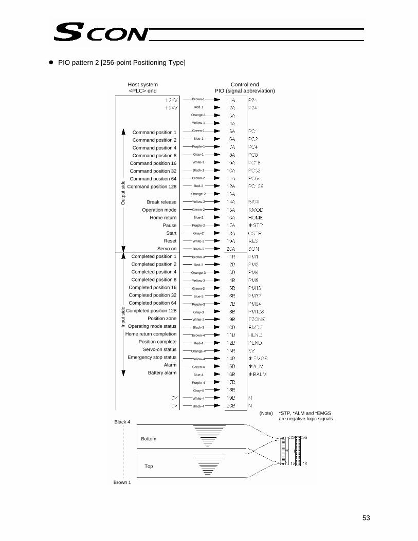
53
PIO pattern 2 [256-point Positioning Type]
Brown-1
Red-1
Orange-1
Yellow-1
Green-1
Blue-1
Purple-1
Gray-1
White-1
Black-1
Brown-2
Red-2
Orange-2
Yellow-2
Green-2
Blue-2
Purple-2
Gray-2
White-2
Black-2
Brown-3
Red-3
Orange-3
Yellow-3
Green-3
Blue-3
Purple-3
Gray-3
Wihte-3
Black-3
Brown-4
Red-4
Orange-4
Yellow-4
Green-4
Blue-4
Purple-4
Gray-4
White-4
Black-4
Command position 1Command position 2Command position 4Command position 8
Command position 16Command position 32Command position 64
Command position 128
Break releaseOperation mode
Home returnPause
StartReset
Servo onCompleted position 1Completed position 2Completed position 4Completed position 8
Completed position 16Completed position 32Completed position 64
Completed position 128Position zone
Operating mode statusHome return completion
Position completeServo-on status
Emergency stop statusAlarm
Battery alarm
Black 4
Brown 1
(Note) *STP, *ALM and *EMGS are negative-logic signals.
Bottom
Top
Host system <PLC> end
Control end PIO (signal abbreviation)
Out
put s
ide
Inpu
t sid
e

54
PIO pattern 3 [512-point Positioning Type]
Brown-1
Red-1
Orange-1
Yellow-1
Green-1
Blue-1
Purple-1
Gray-1
White-1
Black-1
Brown-2
Red-2
Orange-2
Yellow-2
Green-2
Blue-2
Purple-2
Gray-2
White-2
Black-2
Brown-3
Red-3
Orange-3
Yellow-3
Green-3
Blue-3
Purple-3
Gray-3
Wihte-3
Black-3
Brown-4
Red-4
Orange-4
Yellow-4
Green-4
Blue-4
Purple-4
Gray-4
White-4
Black-4
Command position 1Command position 2Command position 4Command position 8
Command position 16Command position 32Command position 64
Command position 128Command position 256
Break releaseOperation mode
Home returnPause
StartReset
Servo onCompleted position 1Completed position 2Completed position 4Completed position 8
Completed position 16Completed position 32Completed position 64
Completed position 128Completed position 256Operating mode status
Home return completionPosition complete
Servo-on statusEmergency stop status
AlarmBattery alarm
Host system <PLC> end
Control end PIO (signal abbreviation)
Black 4
Brown 1
(Note) *STP, *ALM and *EMGS are negative-logic signals.
Bottom
Top
Out
put s
ide
Inpu
t sid
e

55
PIO pattern 4 [7-point Type]
Brown-1
Red-1
Orange-1
Yellow-1
Green-1
Blue-1
Purple-1
Gray-1
White-1
Black-1
Brown-2
Red-2
Orange-2
Yellow-2
Green-2
Blue-2
Purple-2
Gray-2
White-2
Black-2
Brown-3
Red-3
Orange-3
Yellow-3
Green-3
Blue-3
Purple-3
Gray-3
Wihte-3
Black-3
Brown-4
Red-4
Orange-4
Yellow-4
Green-4
Blue-4
Purple-4
Gray-4
White-4
Black-4
Start position 0Start position 1Start position 2Start position 3Start position 4Start position 5Start position 6
Break releaseOperation mode
Home returnPause
ResetServo on
Completed position 0Completed position 1Completed position 2Completed position 3Completed position 4Completed position 5Completed position 6
Zone 1Position zone
Operating mode statusHome return completion
Position completeServo-on status
Emergency stop statusAlarm
Battery alarm
Host system <PLC> end
Control end PIO (signal abbreviation)
Black 4
Brown 1
(Note) *STP, *ALM and *EMGS are negative-logic signals.
Bottom
Top
Out
put s
ide
Inpu
t sid
e

56
PIO pattern 5 [3-point Type]
Brown-1
Red-1
Orange-1
Yellow-1
Green-1
Blue-1
Purple-1
Gray-1
White-1
Black-1
Brown-2
Red-2
Orange-2
Yellow-2
Green-2
Blue-2
Purple-2
Gray-2
White-2
Black-2
Brown-3
Red-3
Orange-3
Yellow-3
Green-3
Blue-3
Purple-3
Gray-3
Wihte-3
Black-3
Brown-4
Red-4
Orange-4
Yellow-4
Green-4
Blue-4
Purple-4
Gray-4
White-4
Black-4
Start position 0Start position 1Start position 2
Break releaseOperation mode
ResetServo on
Rear end detectedFront end detected
Intermediate point detected
Zone 1Position zone
Operating mode statusHome return completion
Servo-on statusEmergency stop status
AlarmBattery alarm
Host system <PLC> end
Control end PIO (signal abbreviation)
Out
put s
ide
Inpu
t sid
e

57
1.3 Details of I/O Signal Functions An input time constant is provided for the input signals of this controller, in order to prevent malfunction due to chattering, noise, etc. Except for certain signals, switching of each input signal will be effected when the signal has been received continuously for at least 6 msec. For example, when an input is switched from OFF to ON, the controller will only recognize that the input signal is ON after 6 msec. The same applies to switching of input signals from ON to OFF (Fig. 1).
Fig. 1 Recognition of Input Signal 1.3.1. Details of Each Input Signal
Command position number (PC1 to PC256) When a movement command is effected upon OFF → ON of the start signal, the nine-bit binary code consisting of signals PC1 to PC256 will be read as the command position number. In the standard or teaching type, six bits of PC1 through PC32 are used. In the 256-point type, eight bits of PC1 to PC128 are used. In the 512-point type, nine bits of PC1 through PC256 are used. The weight of each bit is as follows: 20 for PC1, 21 for PC2, 22 for PC4, …, and 29 for PC256. A desired position number between 0 and 511 (maximum) can be specified.
Brake forced-release signal (BKRL) This signal forcibly releases the brake of an actuator equipped with an electromagnetic brake. If this signal turns ON while the 24-V brake power is supplied to the controller externally and the servo is off, the electromagnetic brake will be forcibly released. This signal is disabled when the actuator is not equipped with electromagnetic brake, 24-V brake power is not supplied externally, servo is on, or brake release switch on the controller is set to the RLS position.
Operating mode (RMOD) This signal is used to switch the internal operating mode of the controller when the AUTO/MANU selector switch on the controller is set to “AUTO.” Turning OFF this signal will switch the operating mode to “AUTO,” while turning it ON will switch the mode to “MANU.” If the selector switch is set to “MANU,” the internal operating mode of the controller will remain “MANU” regardless of the state of this signal. For details on the operating modes, refer to 3, “Operation.”
6 [msec] 6 [msec]
Input signal
Recognition by controller
Not recognized Not recognized

58
Home return (HOME)
The controller will start home return operation upon detection of an OFF → ON edge of this signal. When the home return is complete, the HEND signal will be output. The HOME signal can be input as many times as required. (Note) Even if home return is not performed after the power has been input, the actuator will
automatically perform home return and then move to the target position. Therefore, this signal need not be used at all time. The actuator will move to the home position if “0.00 mm” is set in the position data table. However, this signal is useful when the position data table has no available fields or when the controller is used in the teaching mode.
Pause (*STP)
When this signal turns OFF while the actuator is moving, the actuator will decelerate to a stop. The remaining movement is retained and will be resumed when the signal is turned ON again. If you wish to cancel the move command itself while this signal is OFF, turn the RES signal ON while this signal is OFF to cancel the remaining travel distance. The *STP signal can be used for the following purposes: [1] Provide a low-level safety measure to stop the axis while the servo is ON, such as a sensor that
detects a person approaching the system [2] Prevent contact with other equipment [3] Perform positioning based on sensor or LS detection (Note) If the *STP signal is input while the actuator is performing home return, the movement command
will be retained if the actuator is yet to contact a mechanical end. If the signal is input after the actuator has reversed upon contacting a mechanical end, home return will be performed again from the beginning.
Start (CSTR)
Upon detecting an OFF → ON rise edge of this signal, the controller will read the target point number as a binary code consisting of PC1 to PC32, PC128 and PC256, and execute positioning to the target position of the corresponding position data. Before executing this command, the target position, speed and other operation data must be set in the position table using a PC/teaching pendant. If a start command is issued when home return operation has not been performed yet after the power was input (the HEND output signal is OFF), the controller will automatically perform home return operation before positioning to the target position.
Alarm reset (RES) This signal provides two functions. [1] Reset the alarm output signal (*ALM) that turned OFF due to an alarm
If an alarm has generated, turn ON this signal after confirming the nature of the alarm. The controller will reset the alarm upon detection of a rise edge of the RES signal. (Note) Certain alarms cannot be reset by the RES signal. For details, refer to Appendix 5,
“Troubleshooting.” [2] Cancel the remaining movement when the pause signal is OFF
This function is used when the remaining movement must be cancelled to allow for incremental moves (movements at a constant increment) from the position where the actuator stopped following a sensor detection.

59
Servo ON (SON)
The servo remains ON while this signal is ON. Use this signal if servo ON/OFF control must be performed by the PLC as part of a safety circuit covering the entire system. Whether this signal is enabled or disabled is defined by parameter No. 21, “Servo ON input.” This parameter must always be set. Set “0: [Enable]” if the SON signal is used, or “1: [Disable]” if the signal is not used. (Note) If the SON signal is turned OFF during movement in case of error, the actuator will decelerate to a stop at the emergency-stop torque and then the servo will turn OFF.
Operation mode (MODE) This signal is enabled when parameter No. 25 is set to “1” (= when the teaching type is selected). When this signal is turned ON, the normal operation mode will switch to the teaching mode. (Note) For the controller to switch modes, the *STP, CSTR and RES input signals must also be OFF.
Once the modes have been switched, the MODES output signal turns ON. The PLC should be programmed in such a way that it will confirm that the MODES output signal is ON before accepting any PWRT operation command. To switch the controller back to the normal operation mode, turn this signal OFF. The PLC should be programmed in such a way that it will confirm that the MODES output signal is OFF before accepting any operation command in the normal operation mode.
(Note) The controller will not return to the normal operation mode unless the PWRT input signal is OFF.
Jog/inching switching signal (JISL) When this signal is OFF, the actuator will jog upon detecting the ON edge of the JOG+ or JOG- signal. If this signal is switched while the actuator is jogging, the actuator will decelerate to a stop. When this signal is ON, the actuator will inch upon detecting the ON edge of the JOG+ or JOG- signal. The actuator will continue with the inching operation even after this signal is switched while the actuator is inching. * If the actuator is jogged or inched before home return is completed, the actuator may collide with a
mechanical end because the software stroke limits are not yet effective. Exercise due caution not to perform jogging or inching until home return is completed.
Jog (JOG+, JOG-)
The actuator will jog toward the +/- software stroke limit upon detection of an ON edge of this signal while the JISL signal is OFF. The speed of this jogging movement corresponds to the value set in parameter No. 26, “PIO jog speed.” If both the JOG+ and JOG- signals turn ON at the same time, the actuator will decelerate to a stop if currently moving. If an OFF edge of this signal is detected while the actuator is jogging, the actuator will decelerate to a stop. The actuator will inch in the positive/negative direction upon detection of an ON edge of this signal while the JISL signal is ON. The speed and travel distance of this inching movement correspond to the values set in parameter No. 26, “PIO jog speed” and parameter No. 36, “PIO inching distance,” respectively. The actuator will continue with its inching movement even after an OFF edge of this signal is detected or both the JOG+ and JOG- signals become ON. * If jogging/inching is performed before home return is completed, the actuator may collide with a
mechanical end because the software stroke limits are not yet effective. Exercise due caution. Turning ON the start (CSTR) signal while the actuator is jogging will cause the actuator to decelerate to a stop. If the jog signal is turned ON during normal operation, the actuator will continue with its normal operation (the jog signal will be ignored).

60
Current-position write (PWRT)
This signal is enabled when the aforementioned MODES output signal is ON. If this signal remains ON for 20 msec or more, the controller will read a position number consisting of the binary code specified by PC1 to PC32 that are currently detected, and write the current position data as a target position in the position data table under the corresponding position number. If data other than the target position (speed, acceleration/deceleration, positioning band, etc.) are yet to be defined, the default parameter settings will be written. When the writing completes successfully, the WEND output signal will turn ON. Configure the system in such a way that the PLC will turn OFF the PWRT signal when WEND turns ON. The controller will turn OFF WEND once the PWRT signal turns OFF. (Note) An alarm will generate if a write command is issued when home return has not been performed yet or while the actuator is moving. • Required condition when the servo is on:
This signal is enabled when both the JOG+ and JOG- input signals are OFF, HEND output signal is ON, and MOVE output signal is OFF.
• Required condition when the servo is off: This signal is enabled as long as the HEND output signal is ON. In this condition, however, whether the actuator is being moved by hand or stopped cannot be distinguished. Therefore, this signal should be input after physically checking the actuator operation to confirm that the actuator is stopped.
Start position number (ST0 to ST6) [7-point type]
These signals are effective when “4” is set in parameter No. 25 (= when the air-cylinder type is selected). Upon detection of an OFF → ON rise edge of this signal, the actuator will move to the target position set in the corresponding position data. Before executing this command, the target position, speed and other operation data must be set in the position table using a PC/teaching pendant. If two or more ON edges are detected at the same time, priority will be given to the position command of the smallest number among all detected commands. (Example: If ON edges of ST0 and ST1 are detected at the same time, the actuator will start moving to position 0.) Although commands are executed upon detection of ON signal edge, priority is given to the command that was specified the earliest. In other words, a signal input will not be accepted while the actuator is moving. Even if a different position signal is turned ON while the actuator is moving, the actuator will not commence moving to the new position even after reaching the target position.
Correspondence table of input signals and command positions
Input signal Command position ST0 Position No. 0 ST1 Position No. 1 ST2 Position No. 2 ST3 Position No. 3 ST4 Position No. 4 ST5 Position No. 5 ST6 Position No. 6
If a movement command is issued when the first home return is not yet completed after the power was input, home return will be performed automatically to establish the coordinates first, after which the actuator will move to the target position.
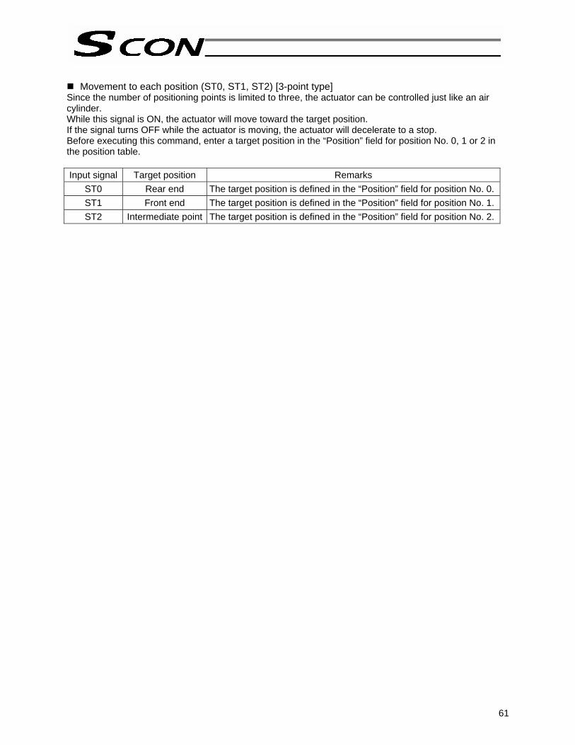
61
Movement to each position (ST0, ST1, ST2) [3-point type]
Since the number of positioning points is limited to three, the actuator can be controlled just like an air cylinder. While this signal is ON, the actuator will move toward the target position. If the signal turns OFF while the actuator is moving, the actuator will decelerate to a stop. Before executing this command, enter a target position in the “Position” field for position No. 0, 1 or 2 in the position table. Input signal Target position Remarks
ST0 Rear end The target position is defined in the “Position” field for position No. 0. ST1 Front end The target position is defined in the “Position” field for position No. 1. ST2 Intermediate point The target position is defined in the “Position” field for position No. 2.

62
1.3.2 Details of Each Output Signal
Completed position number (PM1 to PM256) These signals can be used to check the completed position number when the PEND signal turns ON. The signals are output as a binary code. Immediately after the power is input, all of the PM1 to PM256 signals are OFF. In the standard or teaching type, six bits of PM1 through PM32 are used. In the 256-point type, eight bits of PM1 through PM128 are used. In the 512-point type, nine bits of PM1 through PM256 are used. All of these signals are OFF also when the actuator is moving. As described above, this signal is output only when positioning is completed. (Note) All of these signals will turn OFF when the servo is turned OFF or an emergency stop is actuated.
They will return to the ON status when the servo is turned ON again, provided that the current position is inside the in-position range with respect to the target position. If the current position is outside the range, the signals will remain OFF. When the power is input, the PEND signal will turn ON. These signals are all OFF, this condition is the same as one achieved after positioning to position “0” is completed. Check the position of position 0 after the movement command has completed.
If an alarm is present, the corresponding alarm code (abbreviated form) consisting of four bits from PM1 to PM8 will be output. The meanings of these signals vary between the normal condition and the alarm condition, so be careful not to use them wrongly in the sequence.
Moving (MOVE) This signal is output while the servo is ON and the actuator is moving (also during home return, push & hold operation or jogging). Use the MOVE signal together with the PEND signal to allow the PLC to determine the actuator status. The MOVE signal will turn OFF after positioning or home return is completed or a judgment is made during push & hold operation that the load is being contacted.
Zone (ZONE1) This signal will remain ON while the current actuator position is inside the zone specified by parameters No. 1, “ZONM” and No. 2, “ZONL,” or OFF while the actuator is outside this range. This signal is always effective once home return has been completed and is not affected by the servo status or presence of an alarm. (Note) This signal becomes effective only after the coordinate system has been established following a
completion of home return. It will not be output immediately after the power is turned on. As long as home return has been completed, this signal is enabled even when the servo is off or while an emergency stop is actuated.
Position zone signal (PZONE)
This signal will turn ON when the current actuator position enters the area between the zone boundaries set in the position table. After the current position movement command is completed, the signal will remain effective until the next position movement command is received.
Operating mode status (RMDS) The internal operating mode of the controller is output based on the AUTO/MANU selector switch on the controller and the RMOD signal received by the input port. If the selector switch is set to “AUTO” and the RMOD signal is OFF (AUTO), the controller is in the AUTO (OFF) mode. If the selector switch is set to “MANU” and/or the RMOD signal is ON (MANU), the controller is in the MANU (ON) mode. If the RMOD input is disabled by parameter No. 41, the MODE switch status will be output by this signal.

63
Home return completion (HEND)
This signal is OFF immediately after the power is input, and turns ON in either of the following two conditions: [1] Home return operation has completed with respect to the first movement command issued with the
start signal. [2] Home return operation has completed following an input of the home return signal. Once turned ON, the HEND signal will not turn OFF unless the input power supply is cut off, a soft reset is executed, or the home return signal is input again. The HEND signal can be used for the following purposes: [1] Check prior to establishing the home if movement toward the home direction is permitted, in cases
where an obstacle is located in the direction of the home [2] Use as a condition for writing the current position in the teaching mode [3] Use as a condition for enabling the zone output signal
Position complete (PEND) This signal indicates that the target position was reached and positioning has completed. Use the PEND signal together with the MOVE signal to allow the PLC to determine the positioning status. When the controller becomes ready after the power was input and the servo has turned ON, this signal will turn ON if the position deviation is within the in-position range. Then, when a movement command is issued by turning ON the start signal, the PEND signal will turn OFF. It will turn ON again when the deviation from the target position falls within the in-position range. Once turned ON, the PEND signal will not turn OFF even when the position deviation subsequently exceeds the in-position range. (Note) If the start signal remains ON, the PEND signal will not turn OFF even when the deviation from the target position falls within the in-position range: it will turn ON when the start signal turns OFF. Even when the motor is stopped, the PEND signal will remain OFF if the pause signal is input or the servo is OFF.
Ready (SV) This is a monitor signal indicating that the servo is ON and the motor is ready. The ON/OFF state of this signal is synchronized with the lit/unlit state of the “SV” LED on the front face of the controller enclosure. Use this signal as a condition for starting a movement command on the PLC side. For the signal timings after the power is input, refer to 3.1, “How to Start.”

64
Emergency stop (*EMGS)
This signal remains ON in a normal condition, and will turn OFF if the emergency stop switch is pressed. Program the PLC so that it will monitor this signal and implement appropriate safety measures for the entire system if the signal turns OFF.
Alarm (*ALM) This signal remains ON while the controller is operating properly, and turns OFF when an alarm has generated. Provide an appropriate safety measure for the entire system by allowing the PLC to monitor the OFF status of this signal. For details of alarms, refer to Appendix 5, “Troubleshooting.”
Absolute-battery voltage low warning signal (*BALM) This signal remains ON while the absolute battery voltage is normal when controller is of absolute specification, or when the controller is of incremental specification. It will turn OFF once the absolute battery voltage drops to 3.1 V. If the voltage drops further to 2.5 V, an alarm will generate and the controller will no longer be able to retain position information. As long as the aforementioned alarm is not present, the controller still retains position information and thus operations can be performed properly even when this signal is OFF.
Current operation mode (MODES) This signal is enabled when the teaching type is selected. The MODES signal will turn ON when the teaching mode is enabled upon selection of the teaching mode via the operation mode input signal (MODE signal ON). Thereafter, the MODES signal will remain ON until the MODE signal turns OFF. Configure the system in such a way that the PLC will start teaching operation after confirming that the MODES signal has turned ON.
Write completion (WEND) This signal is enabled only when the teaching type is selected. The WEND signal is OFF immediately after the controller has switched to the teaching mode. It will turn ON when the writing of position data in response to the current-position write signal is completed. When the current-position write signal turns OFF, this signal will also turn OFF. Configure the system in such a way that the PLC will acknowledge completion of writing when the WEND signal turns OFF.
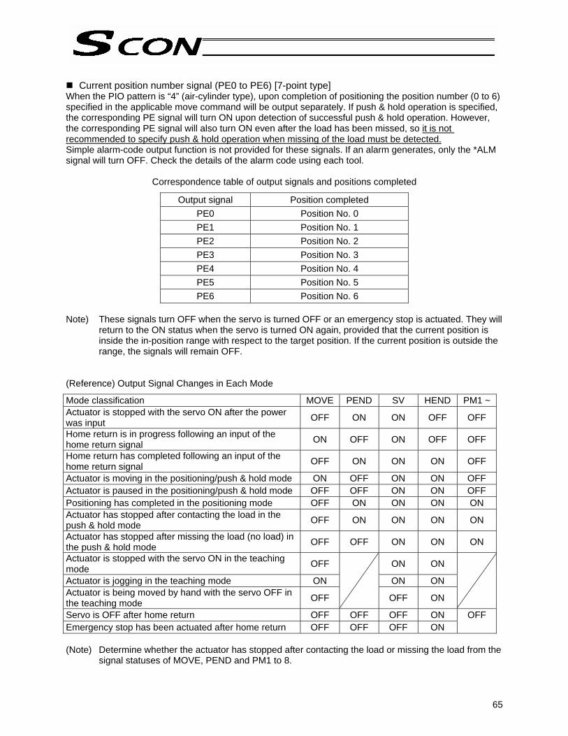
65
Current position number signal (PE0 to PE6) [7-point type]
When the PIO pattern is “4” (air-cylinder type), upon completion of positioning the position number (0 to 6) specified in the applicable move command will be output separately. If push & hold operation is specified, the corresponding PE signal will turn ON upon detection of successful push & hold operation. However, the corresponding PE signal will also turn ON even after the load has been missed, so it is not recommended to specify push & hold operation when missing of the load must be detected. Simple alarm-code output function is not provided for these signals. If an alarm generates, only the *ALM signal will turn OFF. Check the details of the alarm code using each tool.
Correspondence table of output signals and positions completed
Output signal Position completed PE0 Position No. 0 PE1 Position No. 1 PE2 Position No. 2 PE3 Position No. 3 PE4 Position No. 4 PE5 Position No. 5 PE6 Position No. 6
Note) These signals turn OFF when the servo is turned OFF or an emergency stop is actuated. They will
return to the ON status when the servo is turned ON again, provided that the current position is inside the in-position range with respect to the target position. If the current position is outside the range, the signals will remain OFF.
(Reference) Output Signal Changes in Each Mode
Mode classification MOVE PEND SV HEND PM1 ~ Actuator is stopped with the servo ON after the power was input OFF ON ON OFF OFF
Home return is in progress following an input of the home return signal ON OFF ON OFF OFF
Home return has completed following an input of the home return signal OFF ON ON ON OFF
Actuator is moving in the positioning/push & hold mode ON OFF ON ON OFF Actuator is paused in the positioning/push & hold mode OFF OFF ON ON OFF Positioning has completed in the positioning mode OFF ON ON ON ON Actuator has stopped after contacting the load in the push & hold mode OFF ON ON ON ON
Actuator has stopped after missing the load (no load) in the push & hold mode OFF OFF ON ON ON
Actuator is stopped with the servo ON in the teaching mode OFF ON ON
Actuator is jogging in the teaching mode ON ON ON Actuator is being moved by hand with the servo OFF in the teaching mode OFF
OFF ON
Servo is OFF after home return OFF OFF OFF ON OFF Emergency stop has been actuated after home return OFF OFF OFF ON (Note) Determine whether the actuator has stopped after contacting the load or missing the load from the
signal statuses of MOVE, PEND and PM1 to 8.

66
Position detection output at each position (LS0, LS1, LS2) [3-point type]
These signals have the same meanings as the LS signals of an air cylinder. Each signal will turn ON when the current position enters the positioning band of the target position. (Note) Even if the servo turns off or an emergency stop is actuated while the actuator is stopped at the
target position, the signal will remain ON as long as the actuator is inside the positioning band. Output signal Position detected Remarks
LS0 Rear end The detection position is defined in the “Position” and “Positioning band” fields for position No. 0.
LS1 Front end The detection position is defined in the “Position” and “Positioning band” fields for position No. 1.
LS2 Intermediate point The detection position is defined in the “Position” and “Positioning band” fields for position No. 2.

67
2. Data Entry <Basics> To move the actuator to a specified position, a target position must be entered in the “Position” field. A target position can be specified in the absolute mode where a distance from the home is entered, or in the incremental mode where a relative travel from the current position is entered. Once a target position is entered, all other fields will be automatically populated with their default values set by the applicable parameters. The default values vary depending on the characteristics of the actuator. 2.1 Description of Position Table The position table is explained using an example on the PC software screen. (The items displayed on the teaching pendant are different.)
No. Position [mm]
Speed [mm/s]
Acceleration[G]
Deceleration[G]
Push [%]
Threshold [%]
Positioning band [mm]
0 5.00 300.00 0.30 0.30 0 0 0.10 1 380.00 300.00 0.30 0.10 0 0 0.10 2 200.00 300.00 0.30 0.10 0 0 0.10
Zone+ [mm]
Zone- [mm]
Acceleration/deceleration
mode Incremental Command
mode Standstill
mode Comment
0.00 100.00 0 0 0 300.00 400.00 0 0 0 150.00 250.00 0 0 0
(1) No.
• Indicate the position data number. When data is input using the teaching pendant, the “=” sign will be
shown between the “No.” field and the “Position” field. To enter an incremental travel distance, press the minus key here. Nothing needs to be done in the absolute coordinate specification
mode.
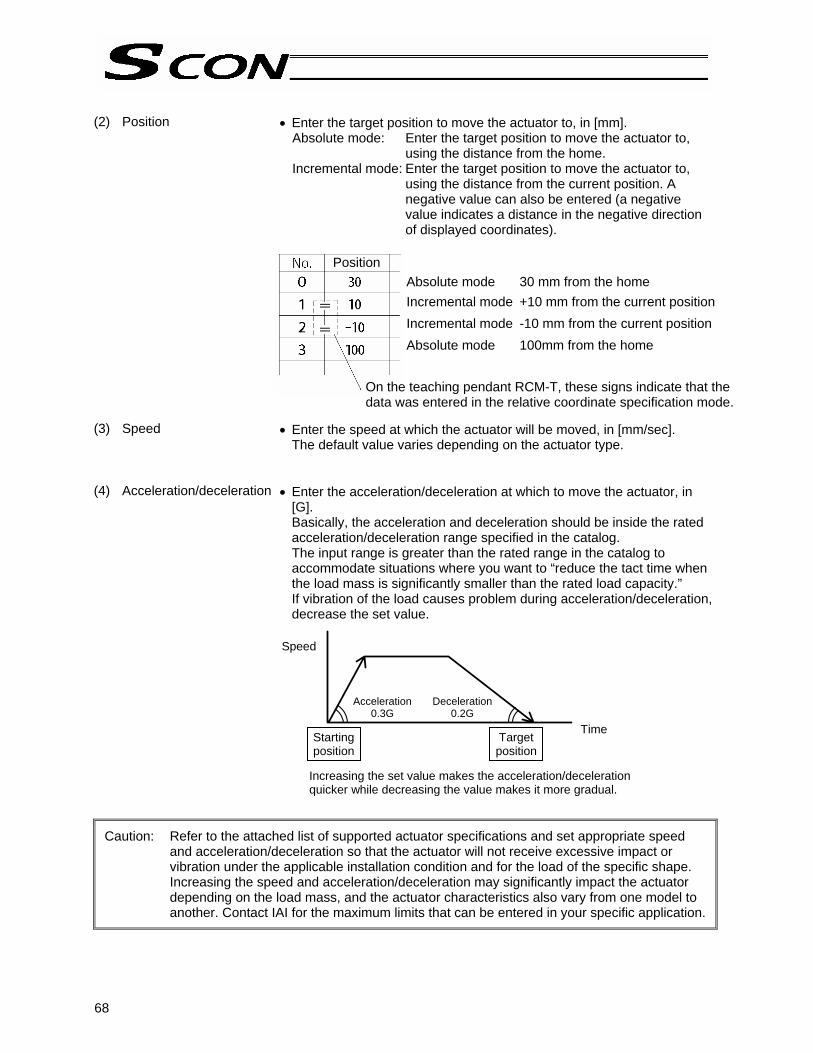
68
(2) Position • Enter the target position to move the actuator to, in [mm].
Absolute mode: Enter the target position to move the actuator to, using the distance from the home.
Incremental mode: Enter the target position to move the actuator to, using the distance from the current position. A negative value can also be entered (a negative value indicates a distance in the negative direction of displayed coordinates).
(3) Speed
• Enter the speed at which the actuator will be moved, in [mm/sec]. The default value varies depending on the actuator type.
(4) Acceleration/deceleration
• Enter the acceleration/deceleration at which to move the actuator, in [G]. Basically, the acceleration and deceleration should be inside the rated acceleration/deceleration range specified in the catalog. The input range is greater than the rated range in the catalog to accommodate situations where you want to “reduce the tact time when the load mass is significantly smaller than the rated load capacity.” If vibration of the load causes problem during acceleration/deceleration, decrease the set value.
Caution: Refer to the attached list of supported actuator specifications and set appropriate speed and acceleration/deceleration so that the actuator will not receive excessive impact or vibration under the applicable installation condition and for the load of the specific shape. Increasing the speed and acceleration/deceleration may significantly impact the actuator depending on the load mass, and the actuator characteristics also vary from one model to another. Contact IAI for the maximum limits that can be entered in your specific application.
Speed
Acceleration0.3G
Deceleration0.2G
Time Starting position
Target position
Increasing the set value makes the acceleration/deceleration quicker while decreasing the value makes it more gradual.
Absolute mode 30 mm from the home Incremental mode +10 mm from the current positionIncremental mode -10 mm from the current position Absolute mode 100mm from the home
On the teaching pendant RCM-T, these signs indicate that the data was entered in the relative coordinate specification mode.
Position

69
(5) Push
• Select either the positioning mode or push & hold mode. The default setting is “0.” 0: Positioning mode (= normal operation) Other than 0: Push & hold mode [%]
• If the push & hold mode is selected, enter the current-limiting value to be applied to limit the AC servo motor current during push & hold operation.
Caution: Take note that if the push force is too small, a false detection may occur during push & hold operation due to sliding resistance, etc.
(6) Threshold • This field is not used for this controller.
The factory setting is “0.”
(7) Positioning band • The meaning of this field varies between “positioning operation” and “push & hold operation.” “Positioning operation”: This field defines how much before the target position the completion signal will turn ON. Increasing the positioning band allows the next operation in the sequence to be started early, and consequently the tact time can be reduced. Set an optimal value by checking the overall balance of the system.
“Push & hold operation”
This field defines the maximum push distance after reaching the target position in push & hold operation. Consider possible mechanical variation of the load and set an appropriate positioning band that will prevent the positioning from completing before the load is contacted.
The position complete signal turns ON here, as completion of push action is recognized after the load has been contacted.
Load
Target positionPositioning band (maximum push distance)
The position complete signal turns ON here.
Positioning band
Target position

70
(8) Zone +/- • This field defines the zone in which PZONE (zone output signal) will
turn ON during operations in PIO pattern 0, 1, 2, 4 or 5. To add flexibility, a different zone can now be set for each target position. [Setting example]
No. Position [mm]
Zone+ [mm]
Zone- [mm]
0 5.00 0.00 100.00 1 380.00 300.00 400.00 2 200.00 150.00 250.00
(9) Acceleration/deceleration
mode
• This field defines the acceleration/deceleration pattern characteristics. The factory setting is “0.” 0: Trapezoid pattern 1: Primary delay filter 2: S-motion
* Set desired acceleration and deceleration in the “Acceleration” and “Deceleration” fields of the position table.
Movement command to position No. 0
Home Target position
Target position
Target position
+ limit Movement command to position No. 1
Movement command to position No. 2
Trapezoid pattern
Speed
Acceleration Deceleration
Time

71
The actuator operates along acceleration/deceleration curves that are more gradual than those of linear acceleration/deceleration (trapezoid pattern). Use this mode in situations where you wish to prevent the load from receiving micro-vibration during acceleration or deceleration. Note, however, that this setting is not reflected in jogging or inching using a PC or teaching pendant.
* Set a desired primary delay in parameter No. 55, “Position-command primary filter time constant.” The setting unit is 0.1 msec, while the setting range is 0.0 to 100.0. The primary delay filter is disabled when “0” is set.
During acceleration, the actuator operates along an acceleration curve that gradually rises until a certain point, and then increases sharply. Use this mode if you wish to set high acceleration/deceleration to meet the required tact time, while still allowing the actuator to accelerate gradually immediately after it starts moving and immediately before stopping. Note, however, that this setting is not reflected in jogging or inching using a PC or teaching pendant.
* Set a desired S-motion level in parameter No. 56, “S-motion ratio setting.” The setting unit is %, while the setting range is 0 to 100. (The graph above assumes an S-motion ratio of 100%.) The S-motion function is disabled when “0” is set.
Primary delay filter
Speed
Time
S-motion
Speed
Time

72
(10) Incremental command
• This field defines whether the position is specified in the absolute mode or incremental mode. The factory setting is “0.” 0: Absolute mode 1: Incremental mode
(11) Command mode
• This field is not used for this controller. The factory setting is “0.”
(12) Standstill mode
• Set a desired power-saving mode to be applied while the actuator stands by after completion of positioning. To save energy when the actuator stands by for a long period of time, this controller provides a mode in which to reduce the power consumption while the actuator is at standstill. The factory setting is “0” (disabled). 0: Power-saving mode is disabled 1: Automatic servo-off mode, with the delay time defined by parameter
No. 36 2: Automatic servo-off mode, with the delay time defined by parameter
No. 37 3: Automatic servo-off mode, with the delay time defined by parameter
No. 38
Automatic servo-off mode
After positioning is completed, the servo will turn off automatically upon elapse of a specified time. (Power is not consumed because holding current does not flow.) When the next movement command is received from the PLC, the servo will turn on and the actuator will start moving.
Servo on
Automatic servo-off mode Green LED (SV) blinks.
T: Delay time (seconds) after positioning is completed until the servo turns off
Start Position complete Servo-on status Actuator movement
When the setting is 1: T corresponds to the value set in parameter No. 36. When the setting is 2: T corresponds to the value set in parameter No. 37. When the setting is 3: T corresponds to the value set in parameter No. 38.

73
Warning: If the next move command is an incremental command (constant pitch feed), never use the automatic servo-off mode. The current position may shift slightly when the servo turns off and then on again.
Caution: • In push & hold operation, the automatic servo-off mode is disabled if push & hold operation has completed successfully. This mode is enabled if the actuator has missed the load. As a basic rule of thumb, do not use the automatic servo-off mode in push & hold operation.
• If the MANU teaching mode, the automatic servo-off mode is disabled.

74
2.2 Explanation of Modes 2.2.1 Positioning Mode Push = 0 The actuator moves to the target position set in the “Position” field of the position table. 2.2.2 Push & Hold Mode Push = Other than 0 (1) Load was contacted successfully Upon reaching the target position set in the “Position” field of the position table, the actuator moves at the push speed for the distance set in the “Positioning band” field. If the actuator contacts the load while moving and the controller recognizes that “push action has completed,” the position complete signal will turn ON.
The push speed is set by parameter No. 34. The factory setting varies with each actuator in accordance with the actuator’s characteristics. Set an appropriate speed by considering the material and shape of the load, among others. Since the maximum speed is 20 mm/s, operate the actuator at a speed not exceeding this value.
Set a positioning band slightly longer than the last position, in order to absorb possible mechanical variation of the load.
“Completion of push action” is determined based on a combination of the current-limiting value set in the “Push” field of the position table and the push completion judgment time set by parameter No. 6. Set an appropriate condition by considering the material and shape of the load, among others. For details, refer to Appendix 3, “Parameter Settings.”
Warning
• If the actuator contacts the load before reaching the target position, an overload or deviation overflow alarm will generate. Pay due attention to the relationship of the target position and the load position.
• The actuator continues to push the load at the push force at standstill determined by the current-limiting value. Since the actuator is not inactive, exercise due caution when handling the machine in this condition.
Speed
Moving distance
Positioning band
Time
Target position
The position complete signal turns ON here.
Speed
Moving distance
Target position
Positioning band (maximum push distance)
The position complete signal turns ON here, as completion of push action is recognized after the load has been contacted.

75
(2) Load was not contacted (missed) If the actuator does not still contact the load after having moved the distance specified in the “Positioning band” field, the position complete signal will not turn ON. Therefore, include timeout check processing in the sequence circuit on the PLC side. • It is recommended that a zone signal be also used as a “simple ruler” to supplement the judgment of
missed load. (3) Load moves during push & hold operation [1] Load moves in the pushed direction
If the load moves in the pushed direction after completion of push action, the actuator will chase the load within the positioning band. If the current drops to below the current-limiting value set in the “Push” field of the position table while the actuator is moving, the position complete signal will turn OFF. The position complete signal will turn ON when the current-limiting value increases to the specified level again.
[2] Load moves in the opposite direction
(Actuator is pushed back by the strong reactive force of the load) If the actuator is pushed back after completion of push action because the reactive force of the load is greater than the thrust force of the actuator, the actuator will be pushed back until its push force balances out with the reactive force of the load. The position complete signal will remain ON.
(Note) If the actuator is pushed back to the target position, an “out of push & hold operation range” alarm will generate.
Speed
Moving distance
Target position
Positioning band (maximum push distance)
The position complete signal will not turn ON if the load has not been contacted.
Speed
Moving distance
Target position
Completion of push action is recognized here.
If the load moves in the pushed direction, the actuator will chase it within the positioning band.
Positioning band (maximum push distance)
Speed
Moving distance
Target position
Completion of push action is recognized here.
Positioning band (maximum push distance)

76
(4) Positioning band was entered with a wrong sign Take note that if a value with a wrong sign is set in the “Positioning band” field of the position table, the operation will deviate by a distance corresponding to “positioning band x 2,” as shown below. 2.2.3 Speed Change during Movement Speed control involving multiple speed levels is possible in a single operation. The actuator speed can be decreased or increased at a certain point during movement. However, the position at which to implement each speed change must be set. 2.2.4 Operation at Different Acceleration and Deceleration Settings If the load is a CCD camera or other precision equipment, the deceleration curb at stop must be made as gradual as possible. To accommodate these sensitive applications, the position table has separate fields for “acceleration” and “deceleration.” For example, you can set the deceleration differently from the acceleration, such as setting 0.3 G (rated acceleration) in “Acceleration” and 0.1 G in “Deceleration.”
Caution: Basically, the acceleration and deceleration should be inside the rated acceleration/deceleration range specified in the catalog. The input range is greater than the rated range in the catalog, but this is only to accommodate situations where you want to “reduce the tact time when the load mass is significantly smaller than the rated load capacity.” If you want to use acceleration/deceleration settings greater than the rating, consult IAI beforehand because it may affect the life of the actuator.
Speed
Moving distance
Positioning band
Positioning band
Positioning band
Actual position reached (the load was missed)
Target position
Position 1 Position 2 Position 1 Position 2 Position 1 Position 2 Position 3
Speed
Acceleration: 0.3 G
Deceleration: 0.1 G
Starting position
Target position
Time

77
ON ON
OFF *STP
Actuator operation Target position
Zone output (ZONE1)
Actuator operation
+ direction Home
Value set in parameter No. 2
Value set in parameter No. 1
2.2.5 Pause The actuator can be paused during movement using an external input signal (*STP). The pause signal uses the contact b logic (always ON) to ensure safety. Turning the *STP signal OFF causes the actuator to decelerate to a stop. When *STP is turned ON subsequently, the actuator will resume the remaining movement. (Note) The deceleration corresponds to the value set in the “Deceleration” field for the current position
number in the position table. 2.2.6 Zone Signal Output The zone output is suitable for the following applications, because a signal can be output when the actuator enters a specified zone during movement: [1] Issue a trigger signal to surrounding equipment to reduce the tact time [2] Prevent contact with surrounding equipment [3] Use as a “simple ruler” in push & hold operation A different method is used for the zone output signal, and for the position zone output signal, to set the zone within which the signal will turn ON.
Zone output signal (ZONE1) Set the signal ON zone using parameters. Parameter No. 1 = Zone boundary+, Parameter No. 2 = Zone boundary-
Position zone output signal (PZONE) Set the signal ON zone using the “Zone boundary-“ and “Zone boundary+” fields of the position table.
Zone output (PZONE)
Actuator operation
+ direction Home
Value set in “Zone boundary-”
Value set in “Zone boundary+”

78
2.2.7 Home Return After the power is turned on, home return must be performed to establish the home position. The method of home return varies depending on the PIO pattern.
When a dedicated input is used [PIO pattern ≠ 5] Home return is performed using the home return (HOME) input. The actuator will return home regardless of whether or not home return has been completed once before. When home return is completed, the home return complete (HEND) output signal will turn ON.
When a dedicated input is not used [PIO pattern = 5]
When a rear end move command is input while home return is not yet completed, the actuator will perform home return first and then move to the rear end.
Η For details, refer to 3.2, “How to Execute Home Return.”
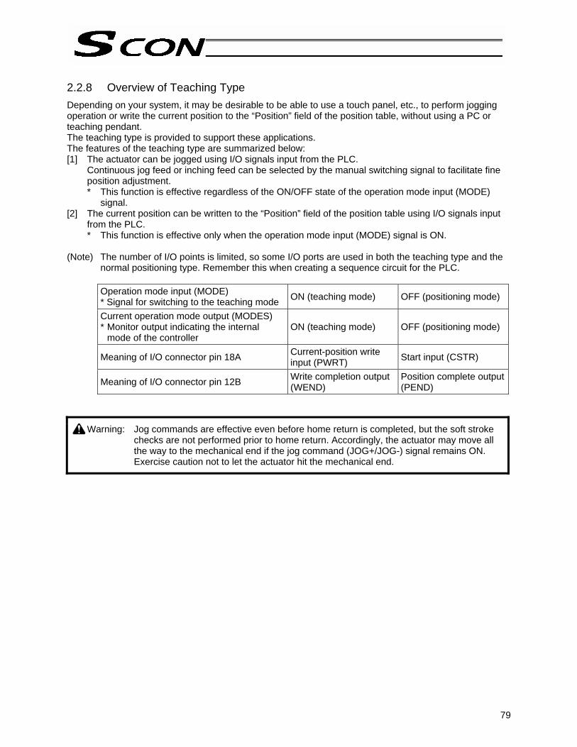
79
2.2.8 Overview of Teaching Type Depending on your system, it may be desirable to be able to use a touch panel, etc., to perform jogging operation or write the current position to the “Position” field of the position table, without using a PC or teaching pendant. The teaching type is provided to support these applications. The features of the teaching type are summarized below: [1] The actuator can be jogged using I/O signals input from the PLC.
Continuous jog feed or inching feed can be selected by the manual switching signal to facilitate fine position adjustment. * This function is effective regardless of the ON/OFF state of the operation mode input (MODE)
signal. [2] The current position can be written to the “Position” field of the position table using I/O signals input
from the PLC. * This function is effective only when the operation mode input (MODE) signal is ON.
(Note) The number of I/O points is limited, so some I/O ports are used in both the teaching type and the
normal positioning type. Remember this when creating a sequence circuit for the PLC.
Operation mode input (MODE) * Signal for switching to the teaching mode ON (teaching mode) OFF (positioning mode)
Current operation mode output (MODES) * Monitor output indicating the internal
mode of the controller ON (teaching mode) OFF (positioning mode)
Meaning of I/O connector pin 18A Current-position write input (PWRT) Start input (CSTR)
Meaning of I/O connector pin 12B Write completion output (WEND)
Position complete output (PEND)
Warning: Jog commands are effective even before home return is completed, but the soft stroke checks are not performed prior to home return. Accordingly, the actuator may move all the way to the mechanical end if the jog command (JOG+/JOG-) signal remains ON. Exercise caution not to let the actuator hit the mechanical end.

80
2.2.9 Overview of 7-point Type The number of positioning points is kept small, or specifically to seven or less. This type assumes simple applications where the PLC ladder sequence only requires a simple circuit configuration. I/O signals provide separate command inputs and movement complete outputs for respective position numbers. Accordingly, the signal pattern is different from the one in the 64-point positioning type (PIO pattern = 0). Example) The differences are explained by using an example of moving the actuator to the target
position for position No. 5. [1] 7-point type * In the 64-point type, a position command input (binary) signal and a start input signal must be turned
ON at staggered timings to initiate movement (refer to the next page). In this type, however, there is only one input signal that needs to be turned ON.
Explanation of I/O signals
Signal name Category Function explanation Direct position command 0 (ST0) Movement command to the target position for position No. 0 Direct position command 1 (ST1) Movement command to the target position for position No. 1 Direct position command 2 (ST2) Movement command to the target position for position No. 2 Direct position command 3 (ST3) Movement command to the target position for position No. 3 Direct position command 4 (ST4) Movement command to the target position for position No. 4 Direct position command 5 (ST5) Movement command to the target position for position No. 5 Direct position command 6 (ST6)
Input
Movement command to the target position for position No. 6 Movement complete 0 (PE0) Indicates that the actuator reached the target position for position No. 0. Movement complete 1 (PE1) Indicates that the actuator reached the target position for position No. 1. Movement complete 2 (PE2) Indicates that the actuator reached the target position for position No. 2. Movement complete 3 (PE3) Indicates that the actuator reached the target position for position No. 3. Movement complete 4 (PE4) Indicates that the actuator reached the target position for position No. 4. Movement complete 5 (PE5) Indicates that the actuator reached the target position for position No. 5. Movement complete 6 (PE6)
Output
Indicates that the actuator reached the target position for position No. 6.
Combination of dedicated movement command input and complete output
Direct position command 5 input (ST5) Movement complete 5 output (PE5) Position complete output (PEND)
No more than 6 msec
Actuator movement
Starting position of movement
Target position

81
[2] 64-point type
Command position 1 input (PC1)
Command position 2 input (PC2) Command position 4 input (PC4)
“5” is indicated by a binary code.
* All other command position inputs (PC8, PC16 and PC32) turn OFF.
At least 6 msec of delay time is needed (ensured by a timer setting on the PLC side).
Start input (CSTR) Completed position 1 output (PM1) Completed position 2 output (PM2) Completed position 4 output (PM4) Position complete output (PEND)
(Remains OFF) The PLC checks these 3 signals to confirm that the completed position number is “5.”
Not to exceed 6 msec
Actuator movement
Starting position of movement
Target position

82
2.2.10 Overview of 3-point Type This type provides a control method adjusted to that of an air cylinder by assuming that the controller is used as an air cylinder. The key differences between this controller and an air cylinder are summarized in the table below. Program appropriate controls by referring to this table.
Item Air cylinder SCON Drive method Air pressure supplied
via electromagnetic valve control
Ball-screw or timing-belt drive using an AC servo motor, or linear-motor drive
Target position setting
Mechanical stopper (including shock absorber)
Desired coordinates are entered in the [Position] field of the position table. Coordinates can be entered from the PC/teaching pendant using the keyboard/keys, or the actuator can be moved to the desired position to read the achieved coordinates directly. Example) 400-mm stroke
Position No. Position 0 5 (mm) Rear end 1 400 (mm) Front end 2 200 (mm) Intermediate point
Target position detection
An external detection sensor, such as a reed switch, is installed.
Determined based on the internal coordinates provided by the position information from the position detector (encoder). Accordingly, external detection sensor is not required.
Speed setting Adjusted by a speed controller.
A desired feed speed is entered in the [Speed] field of the position table (unit: mm/sec). Note that the rated speed is automatically set as the initial value.
Acceleration/ deceleration setting
Determined in accordance with the load, supplied air volume, as well as the performance of the speed controller and electromagnetic valve.
Desired acceleration/deceleration are entered in the [Acceleration] and [Deceleration] fields of the position table (minimum setting unit: 0.01 G). Reference: 1 G = Gravitational acceleration Note that the rated acceleration/deceleration is automatically set as the initial value. Since the acceleration/deceleration can be set in fine steps, a gradual acceleration/deceleration curve can be programmed. Setting a larger value makes the curve steeper, while setting a smaller value makes the curb more gradual.
0.3G 0.1G
Acceleration Deceleration
Starting position of movement
Ending position
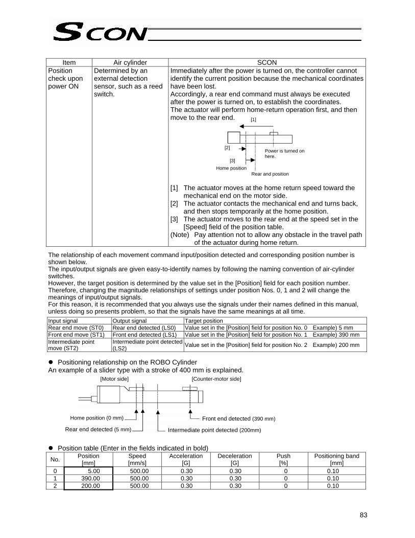
83
Item Air cylinder SCON
Position check upon power ON
Determined by an external detection sensor, such as a reed switch.
Immediately after the power is turned on, the controller cannot identify the current position because the mechanical coordinates have been lost. Accordingly, a rear end command must always be executed after the power is turned on, to establish the coordinates. The actuator will perform home-return operation first, and then move to the rear end. [1] The actuator moves at the home return speed toward the
mechanical end on the motor side. [2] The actuator contacts the mechanical end and turns back,
and then stops temporarily at the home position. [3] The actuator moves to the rear end at the speed set in the
[Speed] field of the position table. (Note) Pay attention not to allow any obstacle in the travel path
of the actuator during home return. The relationship of each movement command input/position detected and corresponding position number is shown below. The input/output signals are given easy-to-identify names by following the naming convention of air-cylinder switches. However, the target position is determined by the value set in the [Position] field for each position number. Therefore, changing the magnitude relationships of settings under position Nos. 0, 1 and 2 will change the meanings of input/output signals. For this reason, it is recommended that you always use the signals under their names defined in this manual, unless doing so presents problem, so that the signals have the same meanings at all time.
Input signal Output signal Target position Rear end move (ST0) Rear end detected (LS0) Value set in the [Position] field for position No. 0 Example) 5 mm Front end move (ST1) Front end detected (LS1) Value set in the [Position] field for position No. 1 Example) 390 mm Intermediate point move (ST2)
Intermediate point detected (LS2) Value set in the [Position] field for position No. 2 Example) 200 mm
Positioning relationship on the ROBO Cylinder
An example of a slider type with a stroke of 400 mm is explained.
Position table (Enter in the fields indicated in bold) No. Position
[mm] Speed [mm/s]
Acceleration [G]
Deceleration [G]
Push [%]
Positioning band [mm]
0 5.00 500.00 0.30 0.30 0 0.10 1 390.00 500.00 0.30 0.30 0 0.10 2 200.00 500.00 0.30 0.30 0 0.10
[1]
[2]
[3] Home position
Rear and position
Power is turned on here.
Home position (0 mm)
Rear end detected (5 mm)
Front end detected (390 mm)
Intermediate point detected (200mm)
[Motor side] [Counter-motor side]

84
2.3 Power-saving Modes at Standby Positions To save energy when the actuator stands by for a long period of time, this controller provides a mode in which to reduce the power consumption while the actuator is at standstill. Use this mode after confirming that it will not present problems to any part of your system. The actuator stands by after completing the home return operation effected by the HOME input signal In this condition, you can select the power-saving mode using parameter No. 53 (Default standstill mode). (This setting is not affected by the value in the “Standstill mode” field of the position table.) The actuator stands by after completing the positioning to the target position set in the “Position” field for the applicable position number In this condition, you can select the power-saving mode based on the value in the “Standstill mode” field of the position table. (This setting is not affected by the value of parameter No. 53.) Meanings of values set in the “Standstill mode” field of the position table and in parameter No. 53 Setting All power-saving modes are disabled. (The actuator is completely stopped.) 0 Automatic servo-off mode. The delay time is defined by parameter No. 36. 1 Automatic servo-off mode. The delay time is defined by parameter No. 37. 2 Automatic servo-off mode. The delay time is defined by parameter No. 38. 3
Automatic servo-off mode After positioning is completed, the servo will turn off automatically upon elapse of a specified time. (Since no holding current flows, power consumption will decrease.) When the next movement command is received from the PLC, the servo will turn on and the actuator will start moving. * Since the servo turns off once, some position deviation may occur. Do not use this function at standby
positions where position deviation will cause problem.
(Note) The automatic servo-off function is disabled in the MANU teaching mode.
Movement command Servo status Actuator movement
Servo on
Automatic servo-off mode (A green LED blinks.)
Target position T: Delay time (seconds) after positioning is
completed until the servo turns off
Position complete signal (parameter No. 39 = 0) Position complete signal (parameter No. 39 = 1)

85
When the PIO pattern is 0, 1, 2, 3 or 4, the servo will turn off and therefore the position complete signal (PEND), completed position number signals (PM1 to PM256) and movement complete signals at respective positions (PE0 to PE6) will turn OFF. However, you can keep the complete signals ON using a parameter in situations where the PLC sequence circuit is designed in such a way that problems will occur if the complete signals turn OFF. Setting of parameter No. 39
(Output mode of position complete signal)
[1] PIO pattern = 0 to 3 Position complete (PEND) signal status, completed position number (PM1 to PM256) signal status [2] PIO pattern = 4 Position complete (PEND) signal status, movement complete (PE0 to PE6) signal status
0 [PEND] The signal will turn OFF unconditionally when the servo turns off. Even when the next movement command is issued and the servo turns on again, the actuator has already started moving to the next target position, so the signal still remains OFF.
1 [INP] Even when the servo is off, the signal turns ON if the current position is within the range set by the “Positioning band” field of the position table, with respect to the target position, and turns OFF if the current position is outside this range.
(Note) The factory setting is “0 [PEND].”
Warning: If the next movement command is specified in the incremental mode (based on constant pitch feed), never use the automatic servo-off mode. The current position may deviate slightly as the servo turns off and then on again.
Caution: In push & hold operation, the automatic servo-off mode is disabled if push & hold operation has completed successfully. This mode is enabled if the actuator has missed the load. As a basic rule of thumb, do not use the automatic servo-off mode in push & hold operation.
86
3. Operation 3.1 How to Start 3.1.1 Incremental Specification
Procedure after initial startup until actuator adjustment [1] Connect the motor relay cable to the MOT connector and encoder relay connector to the PG
connector. [2] Connect the supplied flat cable to the PIO connector (for connection between the host PLC and I/O
unit). [3] Reset the emergency stop or enable the supply of motor drive power. [4] Supply the 24-VDC I/O power (1A/2A pins (+24 V) and 19B/20B pins (0 V) in the PIO connector). [5] Supply the control power and motor power simultaneously (from the same power supply).
* The controller has started properly if the monitor LED [PWR] on the front panel illuminates. If [ALM] illuminates in orange, an alarm has generated. In this case, connect a PC or teaching pendant to check the nature of the alarm and then remove the cause of the alarm by referring to Appendix 5, “Troubleshooting.”
[6] Set the minimum set of required parameters initially. Set the mode selector switch on the front panel to the “MANU” side. On the PC or teaching pendant, set the MANU operation mode to “Teaching mode: Enable safety speed]. Change the necessary parameters in this condition. (Example) • Use a PIO pattern other than “Standard type” → Parameter No. 25 (PIO pattern
selection) • Reduce the safety jog speed → Parameter No. 35 (Safety speed)
[7] Turn on the servo. Turn on the servo using the “servo ON function” of the PC software or teaching pendant. If the actuator enters a servo lock mode and the monitor LED [SV] on the front panel illuminates in green, the controller is functioning properly.
[8] Check the operation of the safety circuit. Confirm that the emergency stop circuit (or motor drive-power cutoff circuit) operates properly.
[9] Perform home return. Overview of operation on the teaching pendant • On the RCM-T, select the “Edit/Teach” screen, bring the cursor to “*Home” in the sub display
area, and then press the Return key. • On the RCM-E, select the “Teach/Play” screen, scroll until “*Home Return” is displayed, and
then press the Return key.

87
[10] Set a target position in the “Position” field of the position table.
Set a target position in the “Position” field of each position table. Determine a desired target position by fine-adjusting the load and hand via jogging or inching. Also adjust the servo gain, if necessary. * Once a target position has been set, other fields (speed, acceleration/deceleration, positioning
band, etc.) will be automatically populated by their default values. Set optimal values for the speed, acceleration/deceleration, positioning band, etc.
* For safety reasons, it is recommended that the safety speed be enabled during the initial movement. To move the actuator at the actual speed set in the “Speed” field of the position table, change the MANU operation mode to [Teaching mode: Disable safety speed].
Home return operation
Hom
e po
sitio
n
Mec
hani
cal e
nd
Pow
er o
n po
sitio
n
Emergency stop not actuated (motor drive power supplied) Safety circuit condition
Supply of 24-VDC I/O power Supply of control power and motor power to controller Servo ON operation Monitor LED [SV/ALM] Ready (SV)
Initial parameter settings
170 msec or less
Green
Set a target position in the “Position” field of the position table via PC or teaching pendant operation Also set optimal values for other items.

88
3.1.2 Absolute Specification (Absolute Reset) (1) Connect the motor cable and encoder cable to the controller. (2) Connect the host PLC to the PIO connector using the supplied flat cable. (3) If two or more controller axes are linked, set the address of each controller using the axis setting
switches. For details, refer to Appendix 4, “PC/Teaching Pendant Connection Method in Multi-axis Configurations.”
(4) Actuate an emergency stop. (5) Connect the battery connector. (6) Supply 24 V for PIO from the flat cable. If an actuator with brake is used, supply 24-V brake power to
the applicable connector on the controller. (7) Supply the control power and motor power simultaneously (from the same power supply).
The alarm output signal (*ALM) turns OFF, an alarm code “0EE” or “0EF” generates, the PIO alarm output signals (PM8 to PM1) become “1101,” and the ALM lamp illuminates. Also, the message “Absolute encoder (2)” appears on the PC/teaching pendant.
(8) Connect a PC or teaching pendant to set the minimum parameters required. • Parameter No. 25, “PIO pattern selection” • If the air-cylinder type is selected, also set parameter No. 27, “Move command type.” For details, refer to Appendix 3, “Parameter Settings.”
(9) Reset the alarm. Operation using the teaching pendant • If you are using the RCM-T or RCM-E, press the BEGIN/END key.
Operation using the PC software Select position data in the main screen, and then click the Alarm button.
The message “Absolute encoder error (2)” disappears. The alarm output signal (*ALM) turns ON, while the alarm code output signals (PM8 to PM1) turn OFF. (Note) The “0EE” and “0EF” alarms cannot be reset via PIO.
(10) Cancel the emergency stop. The EMG lamp turns off.
(11) Input the pause signal (*STP) and servo-on signal (SON) from the PLC (if each signal is enabled). The controller servo turns on, and the SV lamp (LED) illuminates. Also, the position complete output (PEND) and ready output (SV) turn ON.
If the ALM lamp illuminates, an error is present. Refer to the alarm list.

89
(12) Perform home return.
Overview of operation using the teaching pendant • If you are using the RCM-T, select the “Edit/Teach” screen, bring the cursor to “*Home” in the
sub display area, and then press the Return key. • If you are using the RCM-E, select the “Teach/Play” screen, scroll until “*Home Return” is
displayed, and then press the Return key. Overview of operation using the PC software
Select position data in the main screen, and then click the Home button. For details, refer to the operation manual for your teaching pendant or the PC software.
Using a PLC command Refer to 3.1.2, “Absolute Specification” to perform the necessary signal processing corresponding to the PIO pattern currently selected.
Issue a command after confirming that the position complete signal (PEND) is ON.
If home return cannot be executed, check if the *STP and SON signals are ON, if the safety circuit has been reset, and if any error message is displayed, among others.
Once the home return is completed, the home position will be established and stored as position data. This position data will be retained by a battery even after the power is cut off, so home return will not be needed after the power is reconnected.
(13) Set desired data for the target position, speed, acceleration/deceleration, positioning band, etc., in
the position table. For the method to set these data, refer to the operation manual for the teaching pendant or PC software.
The controller is now ready to perform automatic operation with the PLC.

90
Startup Timing Chart Note 1) Always input the 24-V PIO power (and the 24-V brake power if the actuator is equipped with a
brake) before the control power and motor power. Note 2) Supply the control power and motor power simultaneously from the same power supply.
Hom
e po
sitio
n
Mec
hani
cal e
nd
24-V PIO power input
Control power input
Motor power input
Emergency stop status(*EMGS)
Alarm reset • RCM-T/E: Press the
BEGIN/END key. • PC software: Click the
Alarm button.
Alarm output(*ALM)
Alarm code output(PM8 to PM1)
ALM lamp
*Pause input(STP)
Servo-on input(SON)
Servo-on status(SRDY)
Position complete output(PEND)
Home return completion output(HEND)
Home return operation
Sta
rt of
mov
emen
t
Create a position table via operation using the teaching pendant or PC.
Note 1 Note 2
Pause is cancelled.

91
3.1.3 Normal Operation Procedure Normally, the operation procedure follows the steps below:
[1] Cancel the emergency stop or enable the motor drive power supply. [2] Supply the 24-VDC I/O power. [3] Supply the control power and motor power to the controller.
* The controller has started properly if the monitor LED [PWR] on the front panel illuminates. If [ALM] illuminates in red, an alarm has generated. In this case, connect a PC or teaching pendant to check the nature of the alarm and then remove the cause of the alarm by referring to Appendix 5, “Troubleshooting.”
[4] Set the mode selector switch on the front panel of the controller to the “AUTO” side. [5] Input the servo-on signal and pause signal from the PLC. [6] If the controller is of incremental specification, input the home return signal from the PLC to
perform home return operation. [7] Start automatic operation.
Caution: When operating the controller using I/O signals exchanged with the PLC, be sure to set the mode selector switch on the front panel to the “AUTO” side.
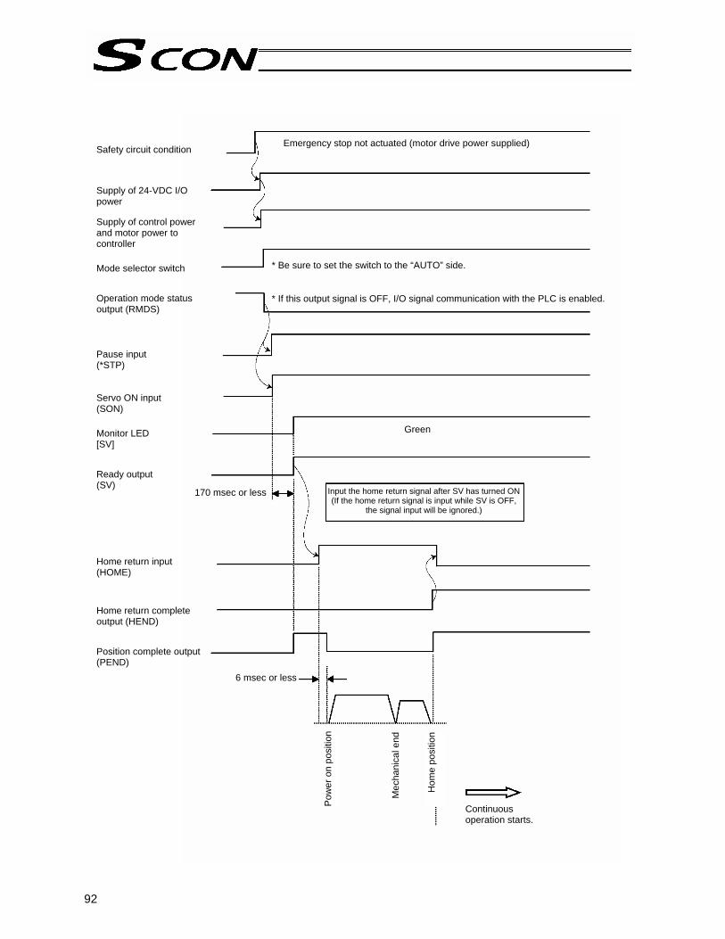
92
Hom
e po
sitio
n
Mec
hani
cal e
nd
Pow
er o
n po
sitio
n
Emergency stop not actuated (motor drive power supplied) Safety circuit condition Supply of 24-VDC I/O power Supply of control power and motor power to controller Mode selector switch Operation mode status output (RMDS) Pause input (*STP) Servo ON input (SON)
Monitor LED [SV] Ready output (SV) Home return input (HOME) Home return complete output (HEND)
Position complete output (PEND)
170 msec or less
Green
* Be sure to set the switch to the “AUTO” side.
* If this output signal is OFF, I/O signal communication with the PLC is enabled.
Input the home return signal after SV has turned ON (If the home return signal is input while SV is OFF,
the signal input will be ignored.)
Continuous operation starts.
6 msec or less
93
3.1.4 Position Table and Parameter Settings Required for Operation
Startup adjustment Immediately after the system has been started, the moving speed can be reduced by the methods specified below to ensure safety of operators and prevent damage to jigs, etc. Change the applicable parameters, if necessary. → For details on the setting-change operations, refer to the operation manual for your PC
software/teaching pendant.
Safety speed during manual feed
To move the actuator using the PC/teaching pendant, set the mode selector switch on the front panel of the controller to the “MANU” side. For safety reasons, it is recommended that the actuator be moved at the safety speed during manual feed. To do this, change the MANU operation mode to [Teaching mode: Enable safety speed] on the PC/teaching pendant. The safety speed is defined by parameter No. 35. Change the parameter value, if necessary. Take note that the maximum speed is limited to 250 mm/s or below. The factory setting is “100 mm/s” or below.
Speed override for movement commands from the PLC
You can lower the feed speed to be applied when the actuator is moved by the movement commands output from the PLC. To lower the speed to below the level set in the “Speed” field of the position table, you can use parameter No. 46 to override the “Speed” field. Actual moving speed = [Speed set in the position table] x [Value of parameter No. 46] ÷ 100 Example) Value in the “Speed” field of the position table 500 (mm/s)
Value of parameter No. 46 20 (%) Under the above settings, the actual moving speed becomes 100 mm/s.
The minimum setting unit is “1%,” while the input range is “1 to 100 %.” The factory setting is “100 %.”

94
Full-scale operation
This product provides energy-saving modes to reduce power consumption in situations where the actuator remains standstill for a long period at a standby position. You can also select the status of position complete signal to be applied if the servo turns off or “position deviation” occurs while the actuator is standing still after completing positioning. Use these functions after confirming that they will not present problems to any part of your system.
Saving energy when the actuator stands by after completing the home return operation effected by the HOME input signal
Applicable to PIO pattern = 0 to 4 In this condition, you can select the automatic servo-off mode using parameter No. 53 (Default standstill mode). (This setting is not affected by the value in the “Standstill mode” field of the position table.)
Saving energy when the actuator stands by for a long time at the target position Common to all PIO patterns
In this condition, you can select the automatic servo-off mode based on the value in the “Standstill mode” field of the position table. (This setting is not affected by the value of parameter No. 53.) → For details, refer to 2.3, “Power-saving Modes at Standby Positions” and Appendix 3.2.2, “Parameters
Relating to Actuator Operating Characteristics.”
Output mode of complete signal
Applicable to PIO pattern = 0 to 4 You can select the status of position complete signal to be applied if the servo turns off or “position deviation” occurs while the actuator is standing still after completing positioning. This setting uses parameter No. 39. Consider the characteristics of the control you need and select an appropriate mode. → For details, refer to Appendix 3.2.3, “Parameters Relating to the External Interface.”

95
Command position 1 to 256 input (PC1 ~ PC256)
Start input (CSTR)
Home return complete output (HEND)
Completed position output (PM1 ~ PM256)
Position complete output
(PEND)
Moving output (MOVE)
Mechanical end
Home position
Target position
Actuator movement
(Note) If the home is not yet established immediately after the power has been turned on, directly
inputting the command position signal and start signal without inputting the home return signal (HOME) first will cause the actuator to perform home return operation and then move to the target position. However, it is recommended that the PLC sequence circuit use the home return signal (HOME) to prevent errors.
[1] PIO pattern = 0 to 3 [2] PIO pattern = 4
Direct position command input (One of ST0 to ST6)
Home return complete output (HEND)
Movement complete output (One of PE0 to PE6)
Mechanical end
Home position
Target position

96
3.2 How Return Operation 3.2.1 Method Using the HOME Input Signal (PIO Pattern = 0 to 4) Since the home return signal (HOME) is provided in PIO patterns 0 to 4, perform home return using this signal. • When the home return signal (HOME) turns ON, the actuator starts moving toward the mechanical end
on the home side. Once the mechanical end is contacted, the actuator reverses its direction and moves, and then stops at the home position.
• At the start of movement, the position complete output (PEND) turns OFF while the moving output (MOVE) turns ON.
• When the actuator stops at the home position, the position complete output (PEND) and home return complete output (HEND) turn ON. On the other hand, the moving output (MOVE) turns OFF.
• On the PLC side, turn OFF the home return signal (HOME) after the home return complete output (HEND) has turned ON. With an absolute type controller, home return operation is not a requirement because the home return completion output (HEND) will turn ON after the power is input to the controller.
Caution: When performing home return, pay attention to the following: [1] Confirm that no obstacle is present in the home return direction. [2] If any obstacle is present in the home return direction, review the PLC sequence
circuit and change the circuit so that home return will be executed only when there is no obstacle.
Mechanical end
Home return input (HOME)
Home return complete output (HEND)
Position complete output
(PEND)
Moving output
(MOVE) Effective in PIO pattern 0 or 1.
Actuator movement
Stops at the home position.
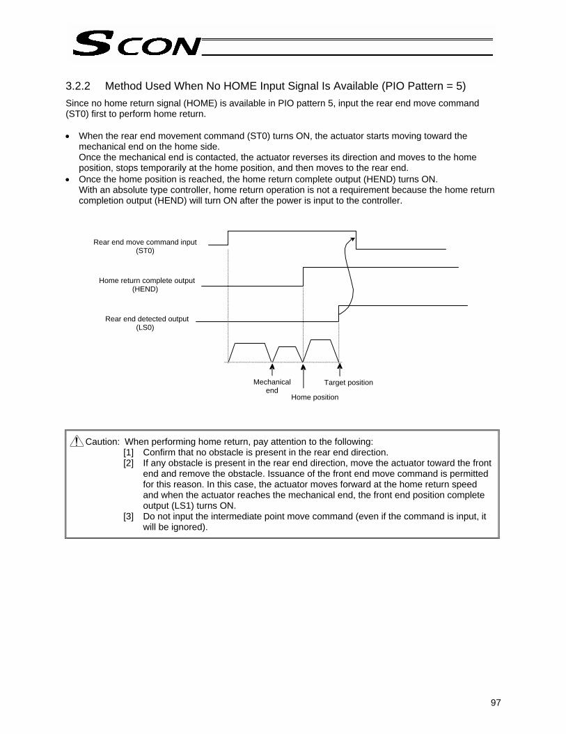
97
3.2.2 Method Used When No HOME Input Signal Is Available (PIO Pattern = 5) Since no home return signal (HOME) is available in PIO pattern 5, input the rear end move command (ST0) first to perform home return. • When the rear end movement command (ST0) turns ON, the actuator starts moving toward the
mechanical end on the home side. Once the mechanical end is contacted, the actuator reverses its direction and moves to the home position, stops temporarily at the home position, and then moves to the rear end.
• Once the home position is reached, the home return complete output (HEND) turns ON. With an absolute type controller, home return operation is not a requirement because the home return completion output (HEND) will turn ON after the power is input to the controller.
Caution: When performing home return, pay attention to the following: [1] Confirm that no obstacle is present in the rear end direction. [2] If any obstacle is present in the rear end direction, move the actuator toward the front
end and remove the obstacle. Issuance of the front end move command is permitted for this reason. In this case, the actuator moves forward at the home return speed and when the actuator reaches the mechanical end, the front end position complete output (LS1) turns ON.
[3] Do not input the intermediate point move command (even if the command is input, it will be ignored).
Rear end move command input (ST0)
Home return complete output (HEND)
Rear end detected output (LS0)
Mechanical end
Home position
Target position

98
3.3 Positioning Mode (Back and Forth Movement between Two Points) Example of use in operation) The actuator moves back and forth between two positions. The position 250
mm from the home is set as position 1, and the position 100 mm from the home is set as position 2. The travel speed to position 1 is set as 200 mm/sec, and to position 2 is set as 100 mm/sec.
Controller
[13] [10] [5] [2]
[1]
[9]
[7]
[15]
[14] [11] [6] [3]
[16] [12] [8] [4]
[1]
[2]
[3]
[4]
[5]
[6]
[7]
[8]
[9]
[10]
[11]
[12]
[13]
[14]
[15]
[16]
P L C
PIO
Signal name
Start
Command position 1
Command position 2
Command position 4
Command position 8
Command position 16
Command position 32
Completed position 1
Completed position 2
Completed position 4
Completed position 8
Completed position 16
Completed position 32
Position complete
Moving
Category
Input
Output
Reference flow
Select/enter command position 1.
Start input ON
Movement to position 1 starts.
Completed position OFF
Position complete output OFF
Moving output ON
Start input OFF
Position complete output ON
Completed position 1 is output.
Moving output OFF
Select/enter command position 2.
Movement to position 1 completes.
Start input ON
Movement to position 2 starts.
Completed position OFF
Position complete output OFF
Moving output ON
Start input OFF
Position complete output ON
Completed position 2 is output.
Moving output OFF
Movement to position 2 completes.

99
Start
Position complete
Moving
Actuator
Movement is complete.
Position table (Field(s) within thick line must be entered.)
No. Position [mm]
Speed [mm/s]
Acceleration [G]
Deceleration [G]
Push [%]
Positioning band [mm]
0 * * * * * * 1 250.00 200.00 0.30 0.30 0 0.10 2 100.00 100.00 0.30 0.30 0 0.10 :
T1: 6 msec or more; time after selecting/entering a command position until the start input turns ON (The scan time of the host controller must be considered.) Each command position must be input after the position complete output has turned ON for the movement to the previous position.
Caution: When the start signal turns ON, the position complete output will turn OFF and the moving output will turn ON. Always turn OFF the start signal after confirming that the start signal is currently ON and the position complete output has turned OFF. If the start input remains ON as shown below, the position complete output will not turn ON even when the actuator movement is completed.
Command position
Start
Position complete
Moving
Completed position
Actuator movement
Speed
Position 1 Position 2 Position 1
Note Note Note
Position 1 Position 2 Position 1
T1 T1 T1 T1
1 msec or less

100
3.4 Push & Hold Mode Example of use in operation) The actuator is caused to move back and forth in the push & hold mode and
positioning mode. The position 280 mm from the home is set as position 1, and the position 40 mm from the home is set as position 2. Movement to position 1 is performed in the push & hold mode (the actuator is caused to contact the load and push it in the counter-motor direction). The maximum push amount at position 1 is set as 15 mm, and the current-limiting value during the push & hold operation by the stepper motor is set as 50%. Movement to position 2 is performed in the positioning mode. The travel speed to position 1 is set as 200 mm/sec, and that to position 2 is set as 100 mm/sec.
Controller
[13] [10] [5] [2]
[1]
[9]
[7]
[15]
[14] [11] [6] [3]
[16] [12] [8] [4]
[1]
[2]
[3]
[4]
[5]
[6]
[7]
[8]
[9]
[10]
[11]
[12]
[13]
[14]
[15]
[16]
P L C
PIO
Signal name
Start
Command position 1
Command position 2
Command position 4
Command position 8
Command position 16
Command position 32
Completed position 1
Completed position 2
Completed position 4
Completed position 8
Completed position 16
Completed position 32
Position complete
Moving
Category
Input
Output
Reference flow
Select/enter command position 1.
Start input ON
Movement to position 1 starts.
Completed position OFF
Position complete output OFF
Moving output ON
Start input OFF
Position complete output ON
Completed position 1 is output.
Moving output OFF
Select/enter command position 2.
Start input ON
Movement to position 2 starts.
Completed position OFF
Position complete output OFF
Moving output ON
Start input OFF
Completed position 2 is output.
Moving output OFF
Movement to position 2 completes.
Move at slow speed after passing position 1.
Load is pushed. Stepper motor current rises to the current-limiting value.
Position complete output turns ON 0.1 mm before position 2.

101
Position table (Field(s) within thick line must be entered.)
No. Position [mm]
Speed [mm/s]
Acceleration [G]
Deceleration [G]
Push [%]
Positioning band [mm]
0 * * * * * * 1 280.00 200.00 0.30 0.30 50 15.00 2 40.00 100.00 0.30 0.30 0 0.10 :
T1: 6 msec or more; time after selecting/entering a command position until the start input turns ON
(The scan time of the host controller must be considered.) Each command position must be input after the position complete output has turned ON for the movement to the previous position.
Conditions for determining completion of push & hold operation Push & hold operation is deemed to have completed upon elapse of the time set by parameter No. 6 (Push completion judgment time) after the motor current reached the current-limiting value set in the “Push” field of the position table. Set an appropriate value by considering the material and shape of the load, and so on. The minimum setting unit is “1 msec,” while the maximum value is “9999 msec.” The factory setting is “255 msec.” (Note) The chart below explains how completion of push & hold operation is determined if the load
shifted during the judgment and the current has changed as a result, based on a judgment time of 255 msec.
If the motor current remains at or above the push current for 200 msec and then drops below this level for 20 msec, the count will decrease by 20. When the push current is reached again thereafter, counting will start from 180. If the motor current remains at or above the push current for 75 msec, the count will increase to 255 and thus push & hold operation will be deemed to have completed. In total, 295 msec was required for the judgment.
T1 T1 T1
Command position
Start
Position complete
Moving
Completed position
Actuator movement
Position 1 Position 2 Position 1
Note Note Note
Position 1 Position 2 Position 1 Speed
Push current
Starting position Target position Counting starts.
The count increases to 200. The count decreases to 180.
The count increases to 255.
Push & hold operation is deemed to have completed.
20 msec
75 msec

102
Speed
Return action
Returned position250.34 mm
Target position 280 mm
Position where the push & hold operation completed
290.34 mm
3.4.1 Return Action after Push & Hold by Relative Coordinate Specification
Positioning mode The reference position is the target position for the position number used in the applicable push & hold operation. In the aforementioned example, the actuator moves to the 240-mm position if position No. 2 is set to -40 mm in the incremental mode (280 – 40 = 240 mm).
Push & hold mode The reference position is the position where the push & hold operation completed. In the aforementioned example, the actuator moves to the 250.34-mm position if position No. 2 is set to -40 mm in the incremental mode and the push & hold operation completed at 290. 34 mm (290.34 – 40 = 250.34 mm). (Note) In this case, the controller determines that the actuator has missed the load and thus does not
turn ON the position complete signal. It is therefore recommended that the zone output signal be used to determine completion of push & hold operation on the PLC side.
Caution: When the start signal turns ON, the position complete output will turn OFF and the moving output will turn ON. Always turn OFF the start signal after confirming that the start signal is currently ON and the position complete output has turned OFF. If the actuator has missed the load, the position complete output will not turn ON as shown below. The completed position will be output and the moving output will turn OFF.
Command position
Start
Position complete
Moving
Completed position
Actuator movement
Position 1 Position 2 Position 1
Position 1 Position 2 Position 1
If the actuator has missed the load, the position complete output will not turn ON.
Speed
Speed
Return action
Returned position240 mm
Position where the push & hold operation completed
Target position 200 mm

103
3.5 Speed Change during Movement Example of use in operation) The actuator speed is reduced at a certain point during movement.
The position 150 mm from the home is set as position 1, and the position 200 mm from the home is set as position 2. The actuator is initially located between the home and position 1. The actuator is moved to position 2 being the target position, at a travel speed of 200 mm/sec to position 1 and that of 100 mm/sec from position 1 to position 2.
Method) In this example, the actuator is caused to move to position 1 and to position 2 successively. Before the actuator is stopped at position 1, command position 2 must be selected/entered and the start signal must be input. To do this, set a wide positioning band at position 1 and cause the start signal for movement to position 2 to be input immediately after the completion signal for movement to position 1 is output. (Command position 2 should be entered while the actuator is moving to position 1.)
Controller
[11] [9] [5] [2]
[1]
[6]
[8]
[13]
[12] [10] [7] [3]
[14] [4]
[1]
[2]
[3]
[4]
[5]
[6]
[7]
[8]
[9]
[10]
[11]
[12]
[13]
[14]
P L C
PIO
Signal name
Start
Command position 1
Command position 2
Command position 4
Command position 8
Command position 16
Command position 32
Completed position 1
Completed position 2
Completed position 4
Completed position 8
Completed position 16
Completed position 32
Position complete
Moving
Category
Input
Output
Reference flow Select/enter command position 1.
Start input ON
Movement to position 1 starts at 200 mm/sec.
Completed position OFF
Position complete output OFF
Moving output ON
Start input OFF
Select/enter command position 2.
Start input ON
Completed position OFF
Position complete output OFF
Start input OFF
Completed position 1 is output.
Moving output OFF
Movement to position 2 completes.
Position complete output turns ON 10 mm before position 1.
Movement to position 2 starts at 100 mm/sec.
Position complete output turns ON 0.1 mm before position 2.
Completed position 2 is output.

104
Position table (Field(s) within thick line must be entered.)
No. Position [mm]
Speed [mm/s]
Acceleration [G]
Deceleration [G]
Push [%]
Positioning band [mm]
0 * * * * * * 1 150.00 200.00 0.30 0.30 0 10.00 2 200.00 100.00 0.30 0.30 0 0.10 :
T1: 6 msec or more; time after selecting/entering a command position until the start input turns ON (The scan time of the host controller must be considered.)
Caution: When the start signal turns ON, the position complete output will turn OFF and the moving output will turn ON. Always turn OFF the start signal after confirming that the start signal is currently ON and the position complete output has turned OFF.
Speed
Position 1 Position 2
Position 1
T1 T1
Position 2
Note Note
Command position
Start
Position complete
Completed position
Moving
Actuator movement
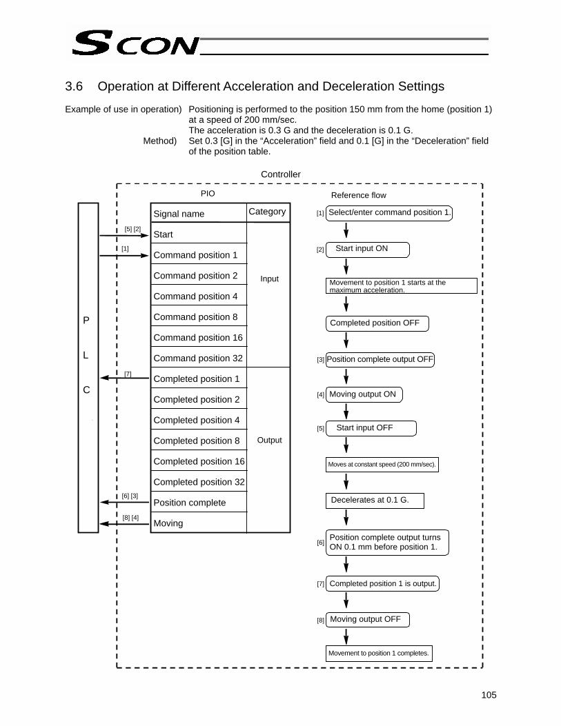
105
3.6 Operation at Different Acceleration and Deceleration Settings Example of use in operation) Positioning is performed to the position 150 mm from the home (position 1)
at a speed of 200 mm/sec. The acceleration is 0.3 G and the deceleration is 0.1 G.
Method) Set 0.3 [G] in the “Acceleration” field and 0.1 [G] in the “Deceleration” field of the position table.
Controller
[5] [2]
[1]
[7]
[6] [3]
[8] [4]
[1]
[2]
[3]
[4]
[5]
[6]
[7]
[8]
P L C
PIO
Signal name
Start
Command position 1
Command position 2
Command position 4
Command position 8
Command position 16
Command position 32
Completed position 1
Completed position 2
Completed position 4
Completed position 8
Completed position 16
Completed position 32
Position complete
Moving
Category
Input
Output
Reference flow
Select/enter command position 1.
Start input ON
Completed position OFF
Position complete output OFF
Moving output ON
Start input OFF
Moving output OFF
Movement to position 1 completes.
Position complete output turns ON 0.1 mm before position 1.
Completed position 1 is output.
Movement to position 1 starts at the maximum acceleration.
Moves at constant speed (200 mm/sec).
Decelerates at 0.1 G.

106
1 msec or less
Start
Position complete
Moving
Actuator
Movement is complete.
Position table (Field(s) within thick line must be entered.)
No. Position [mm]
Speed [mm/s]
Acceleration [G]
Deceleration [G]
Push [%]
Positioning band [mm]
0 * * * * * * 1 150.00 200.00 0.30 0.10 0 0.10 :
T1: 6 msec or more; time after selecting/entering a command position until the start input turns ON (The scan time of the host controller must be considered.)
Caution: When the start signal turns ON, the position complete output will turn OFF and the moving output will turn ON. Always turn OFF the start signal after confirming that the start signal is currently ON and the position complete output has turned OFF. If the start input remains ON as shown below, the position complete output will not turn ON even when the actuator movement is completed.
Speed
Position 1
Position 1
T1
Command position
Start
Position complete
Completed position
Moving
Actuator movement
Deceleration 0.1 G
Positioning band
Acceleration 0.3 G

107
3.7 Pause Example of use in operation) Pause the actuator during movement. [Effective in PIO pattern = 0 to 4]
Method) Use the pause input.
Controller
PIO
Signal name
Start
Command position 1
Command position 2
Command position 4
Command position 8
Command position 16
Command position 32
*Pause
Completed position 1
Completed position 2
Completed position 4
Completed position 8
Completed position 16
Completed position 32
Position complete
Moving
Category
Input
Output
Reference flow
Select/enter a desired command position.
Start input ON
Completed position OFF
Position complete output OFF
Moving output ON
Start input OFF
Moving output OFF
Movement to the selected position completes.
Position complete output ON
Completed position is output.
Movement to the selected position starts.
Pause input OFF (Actuator decelerates to a stop.)
Pause input ON (Movement starts.)
[12][9] [7] [4]
Moving output OFF
Moving output ON
[5][2]
[1]
[8][6]
[11]
[10][3]
[1]
[2]
[3]
[4]
[5]
[6]
[7]
[8]
[9]
[10]
[11]
[12]

108
Command position
Start
Position complete
Completed position
Pause
Moving
Actuator movement
6 msec or more
Command position
Start
Position complete
Completed position
Pause
Reset
Moving
Actuator movement
T1: 6 msec or more; time after selecting/entering a command position until the start input turns ON
(The scan time of the host controller must be considered.)
Caution: When the start signal turns ON, the position complete output will turn OFF and the moving output will turn ON. Always turn OFF the start signal after confirming that the start signal is currently ON and the position complete output has turned OFF.
The remaining movement can be cancelled by turning ON the reset input during pause. (The controller will detect a rise of the reset signal and cancel the remaining movement.)
Speed
4 msec or less
Note
Deceleration to a stop Start of remaining movement
Speed

109
3.8 Zone Signal Output Two types of zone output signals are available: zone output (ZONE1) and position zone output (PZONE). The boundaries defining the signal ON range are set differently for each zone output. [1] Zone output (ZONE1) --- Set by parameter No. 1/No. 2. [2] Position zone output (PZONE) --- Set in the “Zone boundary-“ and “Zone boundary+” fields of the
position table. Whether these signals are available or not varies depending on the PIO pattern, as shown below.
: Available / x: Not available PIO pattern Signal classification
0 1 2 3 4 5 Zone output (ZONE1) x x x Position zone output (PZONE) x Example of use in operation) Move the actuator from the home to the 150-mm position (position 1) and
output a zone signal once the actuator enters the range between 40 mm and 120 mm.
Method) • Zone output (ZONE1) The signal ON range is set by the “Zone boundary+” and “Zone boundary-” parameters.
Parameter No. 1 Zone boundary+ 120 (mm) Parameter No. 2 Zone boundary– 40 (mm)
• Position zone output (PZONE)
The signal ON range is set in the “Zone boundary+” and “Zone boundary-” fields of the position table.
No. Position [mm]
Zone boundary+ [mm]
Zone boundary- [mm]
0 * * * 1 150.00 120.00 40.00
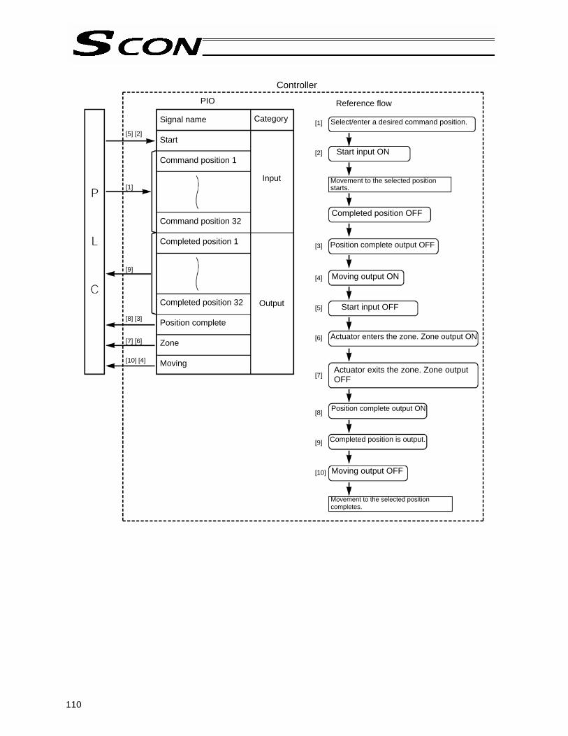
110
Controller
[5] [2]
[1] [9]
[8] [3] [7] [6]
[10] [4]
PIO
Signal name
Start
Command position 1
Command position 32
Completed position 1
Completed position 32
Position complete
Zone
Moving
Category
Input
Output
Reference flow
Select/enter a desired command position.[1] [2] [3] [4] [5] [6] [7] [8] [9] [10]
Start input ON
Completed position OFF
Position complete output OFF
Moving output ON
Start input OFF
Moving output OFF
Movement to the selected position completes.
Position complete output ON
Completed position is output.
Movement to the selected position starts.
Actuator enters the zone. Zone output ON
Actuator exits the zone. Zone output OFF

111
T1: 6 msec or more; time after selecting/entering a command position until the start input turns ON (The scan time of the host controller must be considered.)
Caution: When the start signal turns ON, the position complete output will turn OFF and the moving output will turn ON. Always turn OFF the start signal after confirming that the start signal is currently ON and the position complete output has turned OFF.
Example of other zone output)
Zone output at 120 or more Zone output at 40 or less
Zone boundary+ Maximum stroke length Zone boundary+ 40
Zone boundary– 120 Zone boundary– 0
Zone Zone
120 40
T1
Command position
Start
Position complete
Completed position
Zone
Moving
Actuator movement
Speed
Note
0 mm 40 mm 120 mm 150 mm
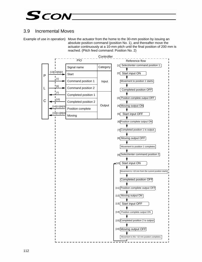
112
[13][10][5][2]
[1]
[1]
[2]
[3]
[4]
[5]
[6]
[7]
[8]
[10]
[9]
[7]
[15]
[14][11][6][3]
[16][11][8][4]
[9]
[11]
[12]
[13]
[14]
[15]
[16]
3.9 Incremental Moves Example of use in operation) Move the actuator from the home to the 30-mm position by issuing an
absolute position command (position No. 1), and thereafter move the actuator continuously at a 10-mm pitch until the final position of 200 mm is reached. (Pitch feed command: Position No. 2)
Controller
P L C
PIO
Signal name
Start
Command position 1
Command position 2
Completed position 1
Completed position 2
Position complete
Moving
Category
Input
Output
Reference flow Select/enter command position 1.
Start input ON
Movement to position 1 starts.
Completed position OFF
Position complete output OFF
Moving output ON
Start input OFF
Position complete output ON
Completed position 1 is output.
Moving output OFF
Select/enter command position 2.
Start input ON
Completed position OFF
Position complete output OFF
Moving output ON
Start input OFF
Completed position 2 is output.
Moving output OFF
Movement to the +10 mm position completes.
Position complete output ON
Movement to position 1 completes.
Movement to +10 mm from the current position starts.

113
Start
Position complete
Moving
Actuator
1 msec or less
Position table (Field(s) within thick line must be entered.)
T1: 6 msec or more; time after selecting/entering a command position until the start input turns ON
(The scan time of the host controller must be considered.)
Caution 1: When the start signal turns ON, the position complete output will turn OFF and the moving output will turn ON. Always turn OFF the start signal after confirming that the start signal is currently ON and the position complete output has turned OFF. If the start input remains ON as shown below, the position complete output will not turn ON even when the actuator movement is completed.
Caution 2: When a soft limit is reached as a result of repeated incremental moves, the actuator will
stop at that position and the position complete signal will be output.
Position [mm]
Speed [mm/ss]
Positioning band [mm]
Zone + [mm]
Zone - [mm] Incremental
* On the teaching pendant screen, this sign indicates that the position is specified in the incremental mode.
0
1
2
…
30.00 10.00 =
100.00 20.00
0.10
0.10
0
190.50
0
29.50
0
1 Incremental feed
Command position
Start
Position complete
Completed position
Moving
Actuator movement
Speed
Position 1 Position 2
Note 1
Note 2
Position 1 Position 2 Position 2
Time
Distance from home
T1 T1
30 40 50 60 70
Movement is complete.
No.
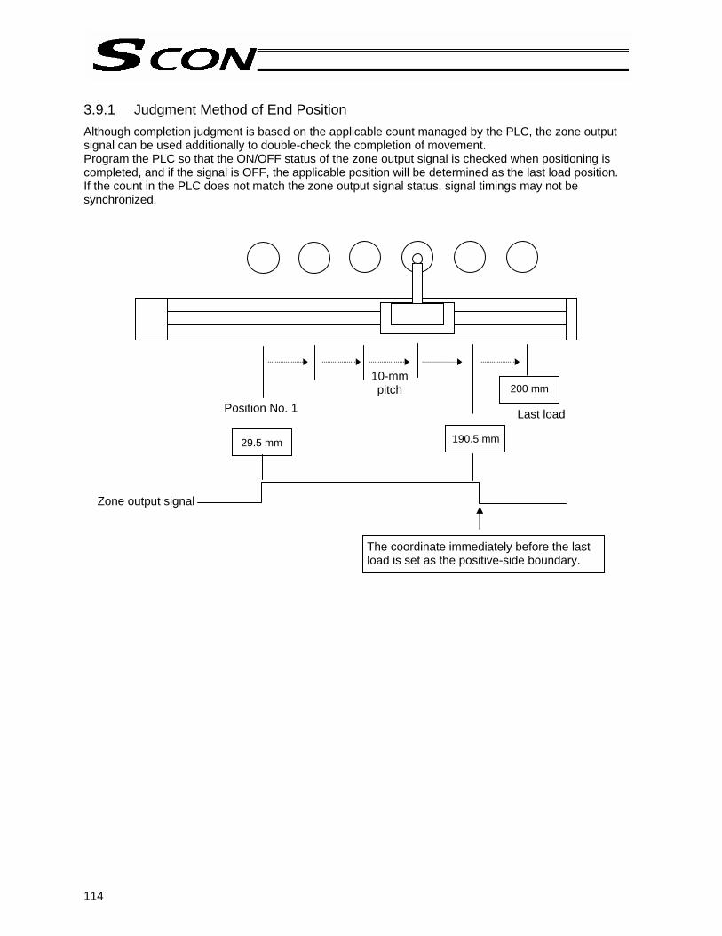
114
3.9.1 Judgment Method of End Position Although completion judgment is based on the applicable count managed by the PLC, the zone output signal can be used additionally to double-check the completion of movement. Program the PLC so that the ON/OFF status of the zone output signal is checked when positioning is completed, and if the signal is OFF, the applicable position will be determined as the last load position. If the count in the PLC does not match the zone output signal status, signal timings may not be synchronized.
29.5 mm 190.5 mm
200 mm
Zone output signal
Position No. 1
10-mm pitch
Last load
The coordinate immediately before the last load is set as the positive-side boundary.

115
3.9.2 Notes on Incremental Mode (1) Positioning mode
If any incremental position number is selected and input and then a start signal is input while positioning is in progress, the actuator will move to the position corresponding to the target position of the initial command plus the incremental distance. (If the incremental distance is a negative value, the actuator will move to the position corresponding to the target position minus the incremental distance.) Example) If the start signal for movement to position 2 is input while the actuator is moving to
position 1, the actuator will move to the position 215 mm from the home.
Position table (Field(s) within thick line must be entered.)
If the start signal for movement to an incremental position number is input multiple times during positioning, the actuator will move to the position corresponding to the initial position plus the “increment x number of times the signal was input.” Example) If the start signal for movement to position 2 is input twice while the actuator is moving to
position 1, the actuator will move to the position 230 mm from the home.
Command position
Start
Position complete
Actuator movement
Speed
Position from home: 230 mm Distance
Position 1 Position 2
Distance Position from home: 215 mm
Command position
Start
Position complete
Actuator movement
Speed
Position 1 Position 2
0 1
2
…
200.00 15.00 =
100.0020.00
0.10
0.10
0
0
0
1
Position [mm]
Speed [mm/ss]
Positioning band [mm]
Incremental Push [%]
* On the teaching pendant screen, this sign indicates that the position is specified in the incremental mode.
Incremental feed
No.
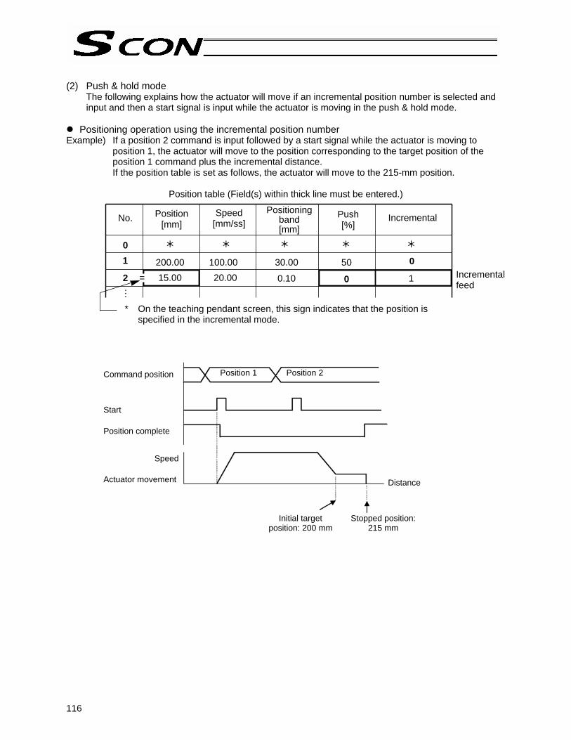
116
(2) Push & hold mode
The following explains how the actuator will move if an incremental position number is selected and input and then a start signal is input while the actuator is moving in the push & hold mode.
Positioning operation using the incremental position number
Example) If a position 2 command is input followed by a start signal while the actuator is moving to position 1, the actuator will move to the position corresponding to the target position of the position 1 command plus the incremental distance. If the position table is set as follows, the actuator will move to the 215-mm position.
Position table (Field(s) within thick line must be entered.)
0 1
2
…
200.00 15.00 =
100.0020.00
30.00
0.10
50
0
0
1
Position [mm]
Speed [mm/ss]
Positioning band [mm]
Incremental Push [%]
* On the teaching pendant screen, this sign indicates that the position is specified in the incremental mode.
Incremental feed
Distance
Command position Start Position complete Actuator movement
Speed
Position 1 Position 2
Initial target position: 200 mm
Stopped position: 215 mm
No.

117
Push & hold operation using the incremental position number
Example) If a position 2 command is input followed by a start signal while the actuator is moving to position 1, a new target position will be set by adding the incremental distance to the current position where the start input was received. Since the target position is indeterminable, never use this method.
Position table (Field(s) within thick line must be entered.)
0 1
2
…
200.00 15.00 =
100.0020.00
30.00
60.00
50
50
0
1
Position [mm]
Speed [mm/ss]
Positioning band [mm]
Push [%]
Incremental
* On the teaching pendant screen, this sign indicates that the position is specified in the incremental mode.
Incremental feed
Command position Start Position complete Actuator movement
15 mm
Distance
Speed
Position 1 Position 2
Initial target position: 200 mm
Position where the start input was received
Position where the push & hold operation completed
No.

118
3.10 Jogging/Teaching Using PIO If the teaching type is selected, you can jog the actuator via operation from the PLC. You can also write the current actuator position to the “Position” field of the position table under a specified position number via operation from the PLC. If the actuator position is written to a blank “Position” field where no position has yet been defined, the positioning band and other fields will be automatically populated by their default values set in the applicable parameters. Example of use in operation) Move the actuator to the target position by inputting a jog command from
the PLC and write the achieved position to position No. 1.
Controller
[1]
[1]
[2]
[3]
[4]
[5]
[6]
[7]
[8]
[4]
[6] [8]
[2]
[4]
[5]
[3]
[7]
P L C
PIO
Signal name
Command position 1
Operation mode
Manual operation switching
Jog+
Jog-
Current-position write
Current operation mode
Moving
Write completion
Category
Input
Output
Operation mode input ON
Reference flow
Current operation mode output ON
Manual operation switching input ON, if manual feed operation is inching feed
Move the actuator to the target position using the Jog+ input or Jog- input. Moving output ON
Command position 1 input ON
Current-position write input ON
Write completion output ON
Current-position write input OFF

119
Jogging/teaching timing
T1: 20 msec or more; time after the current-position write input is turned ON until writing of the current
position is started When the operation mode (MODE) input is turned ON, the current operation mode (MODES) output will turn ON and the teaching mode permitting PIO teaching will become effective. The teaching mode will not become effective unless the operation mode (MODE) input is turned ON while the actuator is stopped. To confirm that the teaching mode is effective, check if the current operation mode (MODES) output is ON. If both the Jog+ input and Jog- input turn ON at the same time, the actuator will stop. In this case, turn both inputs OFF and then restart jogging. The manual operation switching (JISL) input is ON during inching and OFF during jogging. The inching distance is set by parameter No. 48, while the jog speed is set by parameter No. 26. If the current-position write (PWRT) input has remained ON for 20 msec or longer, the current actuator position will be written to the selected command position number. When writing is completed, the write complete (WEND) output will turn ON. When the current-position write (PWRT) input is subsequently turned OFF, the write complete (WEND) output will turn OFF.
If a signal to be written is input from the PLC while the position table screen is open on the PC or teaching pendant, the position data display will not be refreshed. Perform one of the following operations to check the retrieved position data: PC --- Click the button. Teaching pendant --- Open the user adjustment screen and enter “4” as the adjustment number to
reset the software.
Operation mode
Current operationmode
Manual operationswitching
+Jog
-Jog
Command position
Current-position write
Write completion
Position 1

120
3.11 Operation in 7-point Type Separate movement command inputs are provided for the target positions for position Nos. 0 to 6, so simply turn ON the input signal corresponding to the position you wish to move the actuator to, and the actuator will start moving. Example of use in operation) Move the actuator to position No. 0 (5 mm), position No. 1 (200 mm) and
position No. 2 (390 mm) in sequence.
Controller
[1] [4]
[4] [7]
[7] [1]
[3] [5]
[6] [8]
[9] [2]
[1]
[2]
[3]
[4]
[5]
[6]
[7]
[8]
[9]
P L C
Signal name
Direct position command 0
Direct position command 1
Direct position command 2
Movement complete 0
Movement complete 1
Movement complete 2
Category
Input
Output
Reference flow PIO
Direct position command 2 input turns OFF. Direct position command 0 input turns ON.
Starts moving to position No. 0 (5 mm).Movement complete 2 output turns OFF.
Reaches position No. 0 (5 mm). Movement complete 0 output turns ON.
Direct position command 0 input turns OFF. Direct position command 1 input turns ON.
Starts moving to position No. 1 (200 mm). Movement complete 0 output turns OFF.
Reaches position No. 1 (200 mm). Movement complete 1 output turns ON.
Direct position command 1 input turns OFF. Direct position command 2 input turns ON.
Starts moving to position No. 2 (390 mm). Movement complete 1 output turns OFF.
Reaches position No. 2 (390 mm). Movement complete 2 output turns ON.

121
Caution: Movement commands are executed based on the rise edge, so input each signal continuously for 6 msec or more. If two or more movement commands are input simultaneously, they will be executed according to the following priorities: The priorities follow the command numbers in ascending order: [1] Direct position command 0, [2] Direct position command 1, …, [7] Direct position command 6. The sequence circuit on the PLC side must ensure only one command is input at a time.
Direct position command 0 input (ST0)
Direct position command 1 input (ST1)
Direct position command 2 input (ST2)
Movement complete 0 output (PE0)
Movement complete 1 output (PE1)
Movement complete 2 output (PE2)
Actuator movement
Position No. 0 (5 mm)
Position No. 1 (200 mm)
Position No. 2 (390 mm)
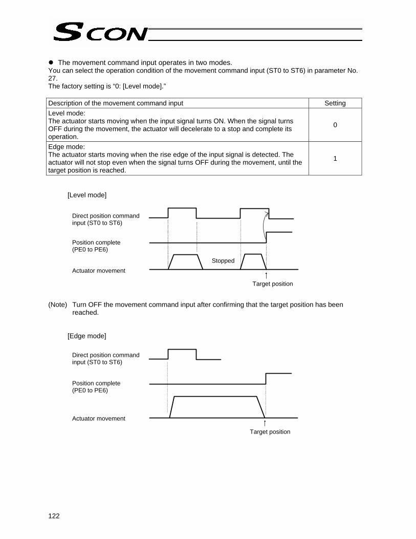
122
The movement command input operates in two modes.
You can select the operation condition of the movement command input (ST0 to ST6) in parameter No. 27. The factory setting is “0: [Level mode].” Description of the movement command input Setting Level mode: The actuator starts moving when the input signal turns ON. When the signal turns OFF during the movement, the actuator will decelerate to a stop and complete its operation.
0
Edge mode: The actuator starts moving when the rise edge of the input signal is detected. The actuator will not stop even when the signal turns OFF during the movement, until the target position is reached.
1
[Level mode] (Note) Turn OFF the movement command input after confirming that the target position has been
reached.
[Edge mode]
Direct position command input (ST0 to ST6) Position complete (PE0 to PE6) Actuator movement
Stopped
Target position
Direct position command input (ST0 to ST6) Position complete (PE0 to PE6) Actuator movement
Target position

123
Handling of the pause (*STP) signal
This signal is a contact B signal, meaning that it must remain ON while the actuator is moving. If the pause signal turns OFF while the actuator is moving, the actuator will decelerate to a stop. The actuator will start moving when the signal turns ON again. Use this signal as an interlock that actuates when an operator entry prohibition sensor or contact prevention sensor is activated.
If the pause signal is not to be used, set parameter No. 15 (Pause input disable selection) to “1,” and the actuator will move even when this signal is OFF.
(Note) When the “edge mode” is selected as the movement command type, you can change the target position while the actuator is stopped with this signal turned OFF, as follows:
[1] Input a reset signal (RES) for 6 msec or more to cancel the remaining travel. Next, turn ON the pause signal, and then input a movement command specifying the new target position. (Example) Turn OFF the pause signal while the actuator is moving under direct position command
1. The actuator decelerates to a stop. → Turn OFF direct position command 1, and turn ON the reset signal for 6 msec or
more. → Turn ON the pause signal again, and input direct position command 2.
[2] After inputting a movement command specifying the new target position, turn ON the pause input. (Example) Turn OFF the pause signal while the actuator is moving under direct position command
1. The actuator decelerates to a stop. → Turn OFF direct position command 1, and turn ON direct position command 2. → Turn ON the pause signal again. The front end is recognized as the new target
position.
Direct position command 1
Direct position command 2
Reset
Pause
Movement complete 2
Actuator movement
(ON for 6 msec or more)
Stopped
The target position is where movement complete 2 turns ON.
Stopped
The target position is where movement complete 2 turns ON.
Direct position command 1
Direct position command 2
Pause
Movement complete 2
Actuator movement

124
3.12 Operation in 3-point Type After the power has been turned on, input the rear end move command first to complete home return, and then perform continuous operation. Example of use in operation) How to move the actuator from the rear end to the front end is explained. Although the actuator does not stop at the intermediate point, you can
increase the positioning band and use the intermediate point detected output signal (LS2) as a quasi zone output signal.
Example of position table
No. Position [mm]
Speed [mm/s]
Acceleration [G]
Deceleration [G]
Push [%]
Positioning band [mm]
Remarks
0 5.00 300.00 0.30 0.30 0 0.10 Rear end 1 380.00 300.00 0.30 0.30 0 0.10 Front end
2 200.00 300.00 0.30 0.30 0 50.00 Intermediate point
Operation timings PLC processing 1: Turn OFF the rear end move command signal (ST0) and intermediate point move
command signal (ST2), and turn ON the front end move command signal (ST1). Operation: [1] The actuator starts moving toward the front end.
[2] When the current position passes 5.1 mm, the rear end detected output (LS0) turns OFF.
[3] When the current position reaches 150 mm, the intermediate point detected output (LS2) turns ON. Once 250 mm is passed, LS2 turns OFF.
PLC processing 2: If necessary, use the intermediate point detected output (LS2) as a trigger signal with respect to surrounding equipment. [4] When the current position reaches 379.9 mm, the front end detected output (LS1)
turns ON. [5] When the current position reaches 380 mm, the actuator stops.
PLC processing 3: Once the front end detected output (LS1) turns ON, the sequence processing at the front end is executed. Upon completion of the sequence processing, the front end move command signal (ST1) turns OFF.
Caution: Provide a ladder sequence circuit where only one move command signal turns ON at a time. If two or more signals are input at the same time, the signals will be processed in the following priorities: Priorities: [1] Rear end, [2] Front end, [3] Intermediate point
365 mm
0.2 mm
100 mm
0.2 mm
Front end move command input (ST1)
Rear end detected output
(LS0)
Intermediate point detected output (LS2)
Front end detected output
(LS1) Speed
Rear end: 5 mm
Intermediate point: 200 mm
Front end: 380 mm
Execution of sequence at the front end
Time
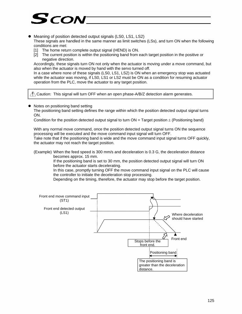
125
Meaning of position detected output signals (LS0, LS1, LS2)
These signals are handled in the same manner as limit switches (LSs), and turn ON when the following conditions are met: [1] The home return complete output signal (HEND) is ON. [2] The current position is within the positioning band from each target position in the positive or
negative direction. Accordingly, these signals turn ON not only when the actuator is moving under a move command, but also when the actuator is moved by hand with the servo turned off. In a case where none of these signals (LS0, LS1, LS2) is ON when an emergency stop was actuated while the actuator was moving, if LS0, LS1 or LS2 must be ON as a condition for resuming actuator operation from the PLC, move the actuator to any target position.
Caution: This signal will turn OFF when an open phase-A/B/Z detection alarm generates.
Notes on positioning band setting
The positioning band setting defines the range within which the position detected output signal turns ON. Condition for the position detected output signal to turn ON = Target position ± (Positioning band) With any normal move command, once the position detected output signal turns ON the sequence processing will be executed and the move command input signal will turn OFF. Take note that if the positioning band is wide and the move command input signal turns OFF quickly, the actuator may not reach the target position.
(Example) When the feed speed is 300 mm/s and deceleration is 0.3 G, the deceleration distance
becomes approx. 15 mm. If the positioning band is set to 30 mm, the position detected output signal will turn ON before the actuator starts decelerating. In this case, promptly turning OFF the move command input signal on the PLC will cause the controller to initiate the deceleration stop processing. Depending on the timing, therefore, the actuator may stop before the target position.
Front end move command input (ST1)
Front end detected output
(LS1) Where deceleration should have started
Stops before the front end.
Front end
Positioning band
The positioning band is greater than the deceleration distance.
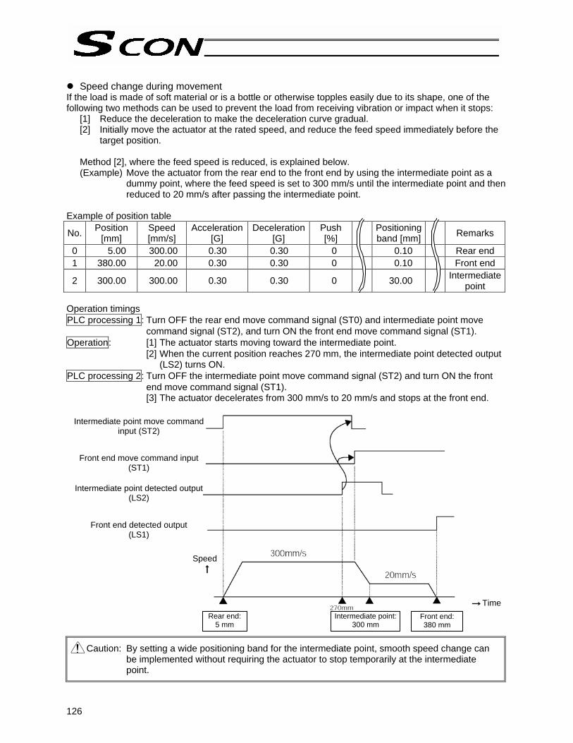
126
Speed change during movement
If the load is made of soft material or is a bottle or otherwise topples easily due to its shape, one of the following two methods can be used to prevent the load from receiving vibration or impact when it stops:
[1] Reduce the deceleration to make the deceleration curve gradual. [2] Initially move the actuator at the rated speed, and reduce the feed speed immediately before the
target position.
Method [2], where the feed speed is reduced, is explained below. (Example) Move the actuator from the rear end to the front end by using the intermediate point as a
dummy point, where the feed speed is set to 300 mm/s until the intermediate point and then reduced to 20 mm/s after passing the intermediate point.
Example of position table
No. Position [mm]
Speed [mm/s]
Acceleration[G]
Deceleration[G]
Push [%]
Positioning band [mm]
Remarks
0 5.00 300.00 0.30 0.30 0 0.10 Rear end 1 380.00 20.00 0.30 0.30 0 0.10 Front end
2 300.00 300.00 0.30 0.30 0 30.00 Intermediate point
Operation timings PLC processing 1: Turn OFF the rear end move command signal (ST0) and intermediate point move
command signal (ST2), and turn ON the front end move command signal (ST1). Operation: [1] The actuator starts moving toward the intermediate point.
[2] When the current position reaches 270 mm, the intermediate point detected output (LS2) turns ON.
PLC processing 2: Turn OFF the intermediate point move command signal (ST2) and turn ON the front end move command signal (ST1). [3] The actuator decelerates from 300 mm/s to 20 mm/s and stops at the front end.
Caution: By setting a wide positioning band for the intermediate point, smooth speed change can be implemented without requiring the actuator to stop temporarily at the intermediate point.
Intermediate point move command input (ST2)
Front end move command input (ST1)
Intermediate point detected output
(LS2)
Front end detected output (LS1)
Speed
Rear end: 5 mm
Intermediate point: 300 mm
Front end: 380 mm
Time
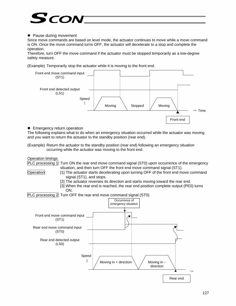
127
Pause during movement
Since move commands are based on level mode, the actuator continues to move while a move command is ON. Once the move command turns OFF, the actuator will decelerate to a stop and complete the operation. Therefore, turn OFF the move command if the actuator must be stopped temporarily as a low-degree safety measure. (Example) Temporarily stop the actuator while it is moving to the front end.
Emergency return operation The following explains what to do when an emergency situation occurred while the actuator was moving and you want to return the actuator to the standby position (rear end). (Example) Return the actuator to the standby position (rear end) following an emergency situation
occurring while the actuator was moving to the front end. Operation timings PLC processing 1: Turn ON the rear end move command signal (ST0) upon occurrence of the emergency
situation, and then turn OFF the front end move command signal (ST1). Operation: [1] The actuator starts decelerating upon turning OFF of the front end move command
signal (ST1), and stops. [2] The actuator reverses its direction and starts moving toward the rear end. [3] When the rear end is reached, the rear end position complete output (PE0) turns
ON. PLC processing 2: Turn OFF the rear end move command signal (ST0).
Front end move command input (ST1)
Front end detected output (LS1)
Speed
Moving Stopped Moving
Front end
Time
Occurrence of emergency situation
Front end move command input (ST1)
Rear end move command input
(ST0)
Rear end detected output (LS0)
Speed
Moving in + direction Moving in – direction
Rear end

128
Chapter 3 Pulse-train Input Mode
1. Overview In this mode, the actuator can be controlled using the positioning control function (pulse-train input) of the host controller (PLC). 1.1 Features
Dedicated home return signal IAI’s original stroke-end push type home return operation is supported in this mode. When this function is used, home return can be performed automatically without having to program a complex sequence or use an external sensor, etc.
Brake control function
The electromagnetic brake power is supplied to the controller from a power supply different from the main power. Since the controller controls the brake, there is no need to program a separate sequence. Also, the electromagnetic brake can be released freely after the main power has been cut off.
Torque limiting function
The torque can be limited (a desired limit can be set by a parameter) using an external signal. When the torque reaches the specified level, a signal will be output. This function permits push & hold operation, press-fit operation, etc.
Feed-forward control function
With this function, response can be improved in certain situations such as when the load inertia ratio is high. Increasing the parameter value will reduce the deviation (difference between the position command and the position feedback), thereby improving response.
Position-command primary filter function
Soft start and stop can be achieved even when the actuator is operated in the command-pulse input mode where acceleration and deceleration are not considered.
Feedback function
Position detection data is output using pulse trains (differential). The current actuator position can be read in real time from the host controller. * The controller is shipped with the feedback pulse output disabled. To use the feedback function, set
user parameter No. 68 to “0 (Enable).”

129
1.2 Standard Accessories (1) Pulse-train control service connector Description: Plug (10114-3000PE by Sumitomo 3M) Shell (10314-52F0-008 by Sumitomo 3M) 1.3 Options
Pulse converter Model: AK-04 Description: Pulse converter + Input/output e-CON connector Use this converter when the host controller outputs open-collector pulses. This converter is used to convert open-collector command pulses output from the host controller, to differential pulses. Converting open-collector pulses to differential pulses has the effect of improving noise resistance. The converter outputs two phases of differential pulses corresponding to those of the line driver 26C31. It comes with an e-CON input/output connector that makes field wiring easy. Basic specifications • Input power supply: 24 VDC ± 10% (50 mA max.) • Input pulse: Open-collector (collector power supply: 12 mA max.) • Input frequency: 200 kHz max. • Output pulse: Corresponding to 26C31 differential output (10 mA max.) • External dimensions: Refer to the figure below (cable connector not included). • Weight: 10 g max. (cable connector not included) • Accessory: Input/output e-CON connector 37104-3122-000L by 3M
Applicable wire: AWG24 to 26, 0.14 to 0.3 mm (max.) EMBED Equation 3 Final outer diameter: ∅1.0 to 1.2 mm
Caution: • Minimize the wiring distance between the host controller and the AK-04. • The input/output connector of the AK-04 can be installed in either direction. Be sure to
connect the correct side. • Exercise caution as the surface temperature of the AK-04 will rise during operation (∆T
≅ 30°C). • When using the AK-04, make sure the converter will not receive any excessive
external force.

130
Pulse-train control service cable
Model: CB-SC-PIOS * Enter the cable length in . Lengths up to 10 m can be specified. Example) 020 = 2 m (The maximum cable length is 2 m if the AK-04 is used to convert open-collector pulses.) Description: Plug + Shell + Shielded cable Use this cable to connect pulse-train control signals to the host equipment. The cable does not have a connector on the host equipment end. The customer should connect the cable to the host equipment by processing the host equipment end of the cable in accordance with the equipment to be connected.
Description: (10114-3000PE by) (10314-52F0-008 by Sumitomo 3M)
Wire Color Symbol Signal name
Connect the shield to the hood using a clamp.
Black White/Black
Red White/Red
Green White/Green
Yellow White/Yellow
Brown White/Brown
Blue White/Blue
Gray White/Gray
0.2 sq., soldered
Pulse-train input
Line-driver output line for feedback pulse output
Host equipment end
Shield
Plug: (Sumitomo 3M) Shell: (Sumitomo 3M)
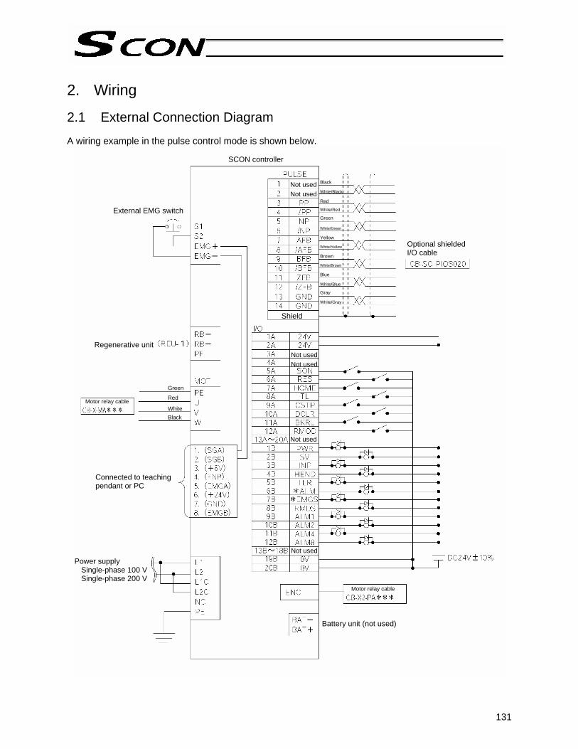
131
2. Wiring 2.1 External Connection Diagram A wiring example in the pulse control mode is shown below.
SCON controller
Connected to teaching pendant or PC
External EMG switch
Motor relay cable
Shield
Motor relay cable
Green
Red White
Black
Black White/Black Red White/Red
Green White/Green Yellow White/Yellow Brown White/Brown Blue White/Blue
Gray White/Gray
Not usedNot used
Optional shielded I/O cable
Not usedNot used
Not used
Not used
Regenerative unit
Power supply Single-phase 100 V Single-phase 200 V
Battery unit (not used)

132
2.2 Command Pulse-train Input Specifications [Differential line-driver input] Applicable line driver: 26C31 or equivalent [Open-collector input]
Caution: • Use a host controller conforming to the figure shown above. • If environmental noise is anticipated, use a host controller of differential line-driver output
specification. If the host controller is of open-collector specification, use the pulse converter AK-04. For details on the pulser converter AK-04, refer to “Pulse converter (Model: AK-04)” in 1.3, “Options.”
Shield
Pulse converter
Host controller

133
2.3 Feedback Pulse Output Part Applicable line receiver: 26C32 or equivalent
Caution: The range in which feedback pulses can be output linearly in accordance with the actuator speed is 0 to 109 kpps. Therefore, use feedback pulses in this range in applications where positions must be read accurately while the actuator is moving, such as when performing closed-loop control or displaying positions during movement. If 109 kpps is exceeded, the pulses corresponding to the traveled distance will still be output.If position data need not follow the speed accurately, such as when checking positions achieved by positioning operations, feedback pulses beyond the above range, but not exceeding 500 kpps, can be used without problem.
Pin No.
Pin No.

134
3. I/O Signal Control and Signal Functions 3.1 Input Signals The input signals of this controller incorporate an input time constant to prevent malfunction due to chattering, noise, etc. (The external forced stop signal (CSTP) and command pulse-train input (PP•/PP, NP•/NP) are excluded.) Accordingly, each input signal should remain ON for at least 6 ms before the signal is recognized. 3.1.1 Servo-on Signal (SON) This signal puts the actuator’s servo motor in a ready state.
The actuator can operate while the SON signal is ON. While this signal is OFF, the actuator cannot be operated even when the controller power is supplied. If this signal turns OFF while the actuator is operating, the actuator will decelerate to a stop at the forced stop torque. After the actuator has stopped, the servo will turn off and the motor will enter a free-run state. At this time, the function selected by the applicable parameter (dynamic brake, electromagnetic brake or deviation counter clearing) is implemented.
Input signal Input signal
Recognized
Not recognized
Dynamic brake
Servo on
Electromagnetic brake

135
Servo-off status
1. Once the actuator stops, no holding torque will be supplied. 2. The pulse-train input, HOME (home return signal), TL (torque-limiting selection signal) and CSTP
(external forced stop signal) are all ignored. 3. The output signals SV (ready signal), INP (position complete signal), HEND (home return
completion signal) and TLR (torque limiting signal) are all cleared (turned OFF). Related parameter The SON signal can be disabled (so that the servo always remains on) using parameter No. 21. When the SON signal is disabled, the servo will turn on automatically once the controller power is input.
3.1.2 Reset Signal (RES) This signal resets the alarms detected by the controller. Function Alarms detected by the controller can be reset when the RES signal is turned ON.
Caution: • If a cold-start level error generates, turning the RES signal ON while the SON (servo-on) signal is OFF will clear the error display. However, the alarm will generate again once the SON signal is turned ON again.
• Identify the cause of the alarm and remove the cause, before restarting the controller.

136
3.1.3 Home Return Signal (HOME) This command signal is used to implement automatic home return. When the HOME signal is turned ON, the command will be processed at the leading edge (ON edge) of the signal and the actuator will perform home return operation automatically. Once the home return is completed, the HEND (home return completion) output signal will turn ON. Program a sequence so that the home will be set (“0” will be entered) in the current value register of the host controller (PLC) using the current-value preset function, etc., when the HOME signal turns ON. * This signal is always enabled while the servo is on. * Even after home return has been completed once, the actuator will perform home return again every
time the HOME signal is turned ON.
Caution: • The HOME signal is given priority over any pulse-train command. Even when the actuator is moving with a pulse-train command, it will start home return once the HOME signal is turned ON.
• The HOME signal is processed only at the leading edge (ON edge) of the signal. • If the SON signal is turned OFF or an alarm is detected during home return, the home
return operation will stop. If the servo is turned off, the home return command will be cancelled even when the HOME signal remains ON. To perform home return again, therefore, turn the HOME signal OFF and then turn it ON again.
• The actuator can be operated without using this function. If this function is not used, however, management of position data will solely be dependent on the host controller.
In this case, take the necessary measures to prevent an over-stroke, such as not sending pulse commands with travel distances exceeding the effective stroke or providing external limit switches, etc., to forcibly stop the actuator upon reaching the stroke ends.

137
3.1.4 Torque-limiting Selection Signal (TL) This signal limits the motor torque. Function While this signal is ON, the actuator thrust (motor torque) can be limited to the torque limit set by the applicable speed/current control parameter. While the TL signal is ON, the TLR (torque limiting) output signal will turn ON once the torque limit is reached. The TL signal is disabled during home return and while the actuator is forcibly stopped.
Caution: • Do not turn OFF the TL signal while the TLR signal is ON. • An excessive deviation (accumulated pulses) may generate while torque is being limited
(the TL signal is ON) (for example, the actuator may receive a load just like it receives a push force in push & hold operation and therefore become no longer operable). If the TL signal is turned OFF in this condition, actuator control will start at the maximum torque the moment the signal changes, thus causing the actuator to move suddenly or run uncontrollably. After the TL signal has turned ON (upon completion of push & hold operation, etc.), always move the actuator in the opposite direction and confirm that the TLR signal turns OFF. If moving the actuator in the opposite direction is difficult, turn off the servo.
Related parameter The TL signal can be disabled using parameter No. 61. If the TL signal is not used, disabled the signal.
3.1.5 Forced Stop Signal (CSTP) This signal is used to forcibly stop the actuator. Function Turn the CSTP signal ON for at least 10 ms continuously to input the signal. When the CSTP signal is received, the controller will decelerate the actuator at the forced stop torque until it stops, and then turn off the servo. At this time, the function (dynamic brake, electromagnetic brake or deviation counter clearing) set by the actuator parameter for forced stop input (0: Enable/1: Disable) will be implemented. For the servo-off status and relevant processing, refer to 3.1.1, “Servo-on Signal (SON).”
Related parameter The forced stop signal (CSTP) can be disabled using parameter No. 67.

138
3.1.6 Deviation-counter Clear Signal (DCLR) This signal is used to clear the deviation counter. Function If a deviation generates while the TL signal is ON, this signal can be used to clear the deviation.
Caution: The actuator will operate if a pulse train is input while the DCLR signal is ON. If DCLR is used, turn this signal ON only when the deviation counter is cleared.
Related parameter The deviation-counter clear signal (DCLR) can be disabled using parameter No. 60.
3.1.7 Brake Forced-release Signal (BKLS) As long as the controller is receiving the 24-V brake power externally for the controlled actuator equipped with an electromagnetic brake, turning this signal ON while the servo is off will forcibly release the electromagnetic brake.
Caution: If the actuator is used in a vertical application, exercise caution when using this signal, because turning off the servo while the brake release signal is ON will cause the actuator to drop.
3.1.8 Operating Mode (RMOD) This signal is used to switch from the AUTO mode to the MANU mode, and vice versa. Function This signal switches the internal operating modes of the controller while the MODE switch on the controller is set to AUTO. Turning this signal OFF will switch the controller to the AUTO mode, while turning it ON will switch the controller to the MANU mode. If the MODE switch is set to MANU, the internal mode of the controller will remain MANU regardless of the state of this signal.
Caution: Once the operating mode switches to MANU, PIO activation will be inhibited. If a tool is connected, however, the PIO activation permission/inhibition setting and safety speed enable/disable setting will follow the selections made for the tool. In the AUTO mode, the settings selected for the tool are disabled. If PIO activation is permitted (monitor mode) in the AUTO mode or MANU mode, actuator operation commands and parameter write commands from the tool are inhibited (limited by the tool).
The operating mode signal (RMOD) can be disabled using parameter No. 41.

139
3.1.9 Command Pulse Input Pulses up to 200 kpps in the open-collector mode, or up to 500 kpps in the differential line-driver mode, can be input. Available command pulses include the 90° phase-difference (phase-A/B x4) signal, pulse train + forward/reverse signal and forward pulse/reverse pulse, and either the positive logic or negative logic can be selected as the input pattern for each pulse signal.
Caution: • The actuator will move in the negative direction (with the motor operating in the forward direction) when a forward pulse is input, or in the positive direction (with the motor operating in the reverse direction) when a reverse pulse is input. (The directions become opposite with the motor-reversing type.)
• As for the forward/reverse directions, pay attention to the host controller setting or PP•/PP and NP•/NP connection.
• Set the actuator acceleration/deceleration on the host controller side. • The actuator acceleration/deceleration should not exceed the rated
acceleration/deceleration of the applicable actuator. (The rated acceleration/deceleration of each actuator is specified in the actuator’s catalog.)
* The rotating direction of the motor is defined so that the counterclockwise direction as viewed from the end of the load shaft represents the forward direction.
Related parameter Six command pulse patterns can be set in the command-pulse input mode.
Command pulse-train pattern Input terminal Forward Reverse
Neg
ativ
e lo
gic
Posi
tive
logi
c
Forward pulse train
Reverse pulse train A forward pulse train indicates motor revolutions in the forward direction, while a reverse pulse train indicates motor revolutions in the negative direction.
Pulse train
Sign
Command pulses indicate motor revolutions, while a command sign indicates a rotating direction.
Phase-A/B pulse train
Phase-A/B x4 pulses with a 90° phase difference indicate motor revolutions and a rotating direction.
Forward pulse train
Reverse pulse train
Pulse train
Sign
Phase-A/B pulse train

140
3.2 Output Signals 3.2.1 System Ready Signal (PWR) After the main power has been input, this signal will turn ON once the SCON enters a ready state. Function The signal will turn ON once the SCON enters a ready state after the main power has been input and the controller has been initialized successfully, regardless of the servo status or whether an alarm is present, etc. Even if an alarm is present, this signal is ON as long as the SCON is ready. This signal is synchronized with the illumination of the PWR lamp (green) on the front face of the controller. 3.2.2 Servo-on Status Signal (SV) This signal is output when the servo is on. Function When the SON (servo-on) signal turns ON, the servo will turn on and the controller will become ready (pulse-train inputs can be accepted) (pulse-train inputs can be accepted = pulse mode). The SV signal turns ON in this condition. It will turn OFF when the servo is turned off due to a SON signal OFF. This signal is synchronized with the illumination of the SV lamp (green) on the front face of the controller. 3.2.3 Position Complete Signal (INP) This signal will turn ON when the deviation (accumulated pulses) on the deviation counter enters the in-position range, and remain ON while the deviation is inside this range. Function This signal will turn ON when the accumulated pulses on the deviation counter enter the range of pulses set in the position control parameter for in-position band, and remain ON while the accumulated pulses remain inside this range. This signal is OFF while the servo is off.
Caution: • This signal will turn ON when the servo turns on (because positioning is executed at the current position where the servo turns on).
• Since this signal turns ON only based on the deviation (accumulated pulses), setting an excessively large value in the position control parameter for in-position band will cause the signal to turn ON while the actuator is still operating at slow speed (i.e., positioning is not yet completed) as long as the current actuator position is inside the in-position band.

141
3.2.4 Home Return Completion Signal (HEND) This signal will turn ON when home return is completed and the coordinate system is established. Function This signal will turn ON when the home return initiated by the applicable signal, teaching pendant or PC software is completed. The signal will turn OFF once the servo turns off. After the servo is turned off, perform home return again.
Caution: • The software stroke limits set by the actuator parameters remain effective only while this signal is ON.
• Although the actuator can be operated without using this function, if this function is not used the necessary measures must be taken such as not sending pulse commands with travel distances exceeding the effective stroke or providing external limit switches to forcibly stop the actuator upon reaching the stroke ends.
3.2.5 Torque Limiting Signal (TLR) This signal will turn ON when the torque reaches the limit while torque is being limited. Function This signal will turn ON when the actuator thrust (motor torque) reaches the torque limit set by the torque limit parameter while the TL (Torque-limiting selection) signal is ON. This signal will turn OFF when the motor torque lowers.
Caution: • Even if the TL signal is turned ON, the TLR signal will not turn ON unless the actuator torque reaches the specified torque.
• Do not turn the TL signal OFF while this signal is ON. (For details, refer to “Caution” in 3.1.4, “Torque-limiting Selection Signal (TL).”)

142
3.2.6 Alarm/Failure Signal (*ALM) This signal will turn OFF when the SCON’s protective circuit (function) detects an error. Function This signal will turn OFF when any of the controller’s protective circuits (functions) actuates upon detecting an alarm and the base cutoff function is executed. Once the cause of the alarm has been removed, this signal can be turned ON by turning the RES (reset) signal ON. (This does not apply to cold-start level alarms.) When an alarm is detected, the ALM LED on the front face of the controller will illuminate. This LED remains unlit in a normal state.
Caution: • If a cold-start level error generates, turning the RES signal ON while the SON (servo-on) signal is OFF will clear the error display. However, the alarm will generate again once the SON signal is turned ON again.
• Alarm codes can be checked using the teaching pendant or PC software. The controller can store up to 16 past alarms, with each alarm shown with the time of occurrence, to let you identify which alarm occurred when.
Controller alarm list (PC software)
Alarm code Alarm message Time of occurrence

143
3.2.7 Feedback-pulse Output Signals (AFB•/AFB, BFB•/BFB, ZFB•/ZFB, GND) Data of detected positions are output using differential pulses. Function Data of detected positions are output using differential pulses (phases A, B and Z). The host controller can read the current actuator position in real time using a counter function, etc.
Related parameter The resolution of output pulses is determined based on the electronic gear ratio of input pulses set by the applicable position control parameters, where the resolution of output pulses is the same as that of command pulses. A desired feedback-pulse output pattern can be set using the user parameter for feedback pulse pattern. These pulse signals can be disabled using user parameter No. 68, “Enable/disable feedback pulses.” Set this parameter to “Disable” if the feedback pulses are not used.
Caution: • If these signals are to be read by the host controller to set a closed loop, set a logically consistent sequence to implement the applicable processing.
• If the actuator encoder is not a serial encoder, the phase-Z signal is output directly. If the actuator uses a serial encoder, the phase-Z pulse is output within a mechanical-angle range of ±0.5° from the zero (home) position. Based on the communication cycle with the encoder, this accuracy can be assured when the motor speed is 100 rpm or below.

144
4. How to Switch to the Pulse-train Control Mode Change the position of the piano switch located on the front panel of the controller. Piano switches
Name Description
1 Operation mode selector switch OFF: Positioner mode, ON: Pulse-train mode * The setting will become effective after the power is reconnected.
2 Used by the manufacturer for adjustment purposes. Keep the switch in the OFF position.
Front panel
[1] Set SW1 to the ON position (tilt the switch to the left) when the power is still off.
[2] Turn on the power.

145
5. Parameters 5.1 Parameter Settings Required for Operation Parameters can be set or changed using the teaching pendant or PC software. After a parameter has been changed, the new setting will become effective once a “software reset” is performed using the teaching pendant or PC software or the power is reconnected. 5.1.1 Basic Settings The parameters that must be set before the actuator can be operated are explained below. (The following parameters are all you need to set, if the actuator performs only positioning operation.) (1) Electronic gear User parameter Nos. 65/66, “Electronic gear numerator/denominator”
Name Symbol Unit Input range Default setting (reference)
Electronic gear numerator CNUM - 1 ~ 4096 2048
Electronic gear denominator CDEN - 1 ~ 4096 125
These parameters are used to determine the unit travel distance of the actuator per each command pulse-train input pulse. Unit travel distance for linear axis = Minimum travel unit (1, 0.1, 0.01 mm, etc.) per pulse Unit travel distance for rotational axis = Minimum travel unit (1, 0.1, 0.01 deg, etc.) per pulse
Electronic-gear calculation formula Linear axis Rotational axis Reference The actuator speed is calculated by the formula below:
Speed = Unit travel distance x Input pulse frequency (Hz) Take note that setting the unit travel distance too small may prevent the actuator from reaching the maximum speed in certain conditions.
(mm/pulse) distance lUnit trave(mm/rev) lead screw Ball
v)(pulses/re pulsesencoder ofNumber (CDEN)r denominatogear Electronic
(CNUM)numerator gear Electronic×=
)(deg/pulse distance lUnit traveaxis rotational of ratioGear (deg/rev) 360v)(pulses/re pulsesencoder ofNumber
(CDEN)r denominatogear Electronic(CNUM)numerator gear Electronic
××
=
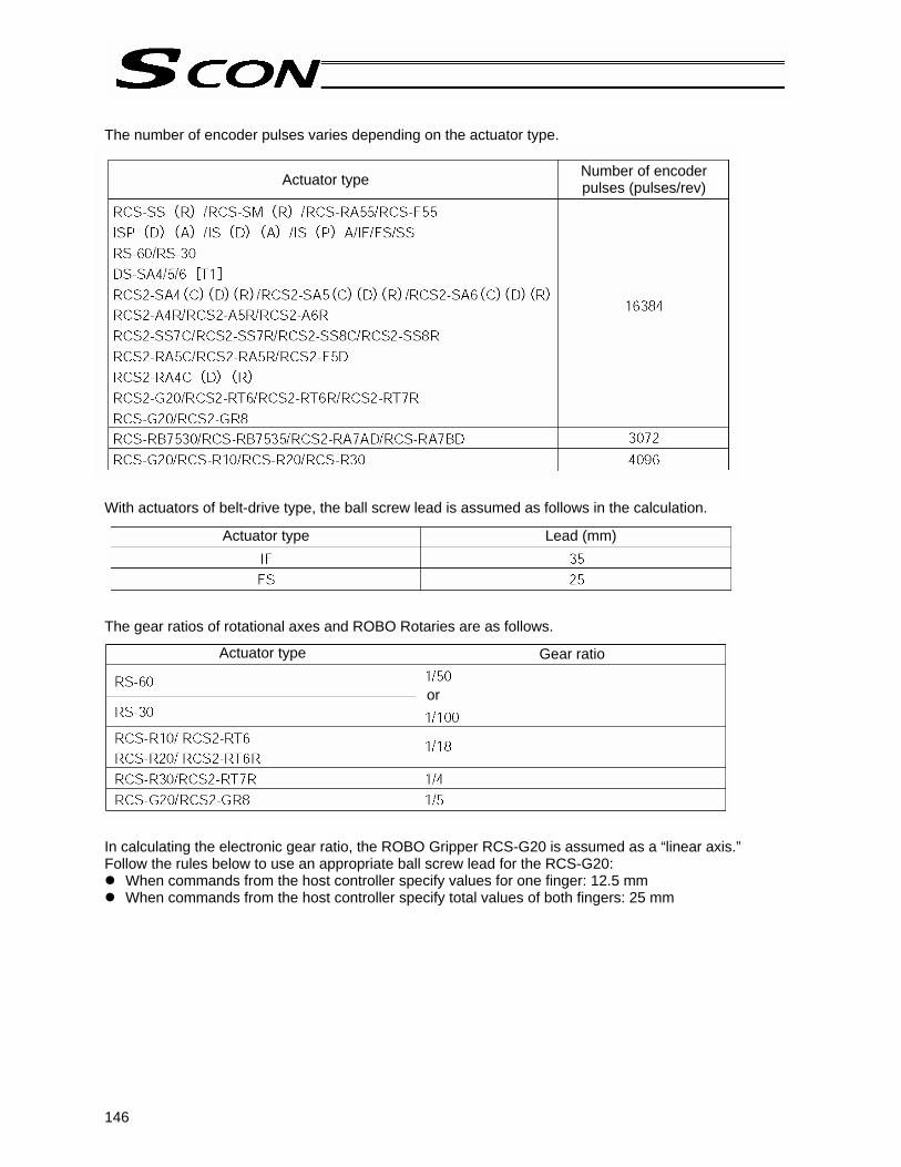
146
The number of encoder pulses varies depending on the actuator type. With actuators of belt-drive type, the ball screw lead is assumed as follows in the calculation. The gear ratios of rotational axes and ROBO Rotaries are as follows. In calculating the electronic gear ratio, the ROBO Gripper RCS-G20 is assumed as a “linear axis.” Follow the rules below to use an appropriate ball screw lead for the RCS-G20:
When commands from the host controller specify values for one finger: 12.5 mm When commands from the host controller specify total values of both fingers: 25 mm
Actuator type Number of encoder pulses (pulses/rev)
Actuator type Lead (mm)
Actuator type Gear ratio
or

147
Calculation example
To set the unit travel distance to 0.01 (1/100) (mm) for an actuator with a ball screw lead of 10 (mm), equipped with an encoder of 16,384 (pulses/rev). The electronic gear numerator (CNUM) is calculated as 2,048, while the electronic gear denominator (CDEN) is calculated as 125. Based on these settings, the travel distance per each command pulse-train input pulse becomes 0.01 (mm).
Caution: • Reduce the electronic gear numerator (CNUM) and electronic gear denominator (CDEN) using the largest possible common divisor so that the two will become integers of 4,096 or below. CNUM and CDEN must also satisfy the relational expressions specified below:
• Do not set a minimum travel unit smaller than the encoder resolution. The actuator will not move until command pulses equal to or greater than the encoder resolution accumulate.
(mm/pulse) distance lUnit trave(mm/rev) lead screw Ball
v)(pulses/re pulsesencoder ofNumber (CDEN)r denominatogear Electronic
(CNUM)numerator gear Electronic×=
(CNUM)(pulses) pulsesencoder ofNumber v)(pulses/re lead screw Ball
(mm) Stroke2 ××≥
(CDEM)(pulses) pulsesencoder ofNumber v)(pulses/re lead screw Ball
(mm) Stroke2 ××≥
v)(pulses/re pulsesencoder ofNumber (mm/rev) lead screw Ball(mm/pulse) axislinear for resolutionEncoder =
v)(pulses/re pulsesencoder ofNumber axis rotational of ratioGear (deg/rev) 360)(deg/pulse axis rotationalfor resolutionEncoder ×
=

148
(2) Command pulse mode User parameter No. 63, “Command-pulse input mode”
Name Symbol Unit Input range Default setting (reference)
Command-pulse input mode CPMD - 0 ~ 2 1
Set a desired pulse-train input pattern for command pulse input (PP•/PP, NP•/NP). * Whether to apply the positive logic or negative logic is set in accordance with (3), “Input polarity in the
command pulse mode.” (3) Input polarity in the command pulse mode User parameter No. 64, “Command-pulse input mode polarity”
Name Symbol Unit Input range Default setting (reference)
Command-pulse input mode polarity POLE - 0 ~ 1 0
Setting Positive logic: 0 Negative logic: 1
Command pulse-train pattern Input terminal Forward Reverse
Neg
ativ
e lo
gic
Posi
tive
logi
c
Forward pulse train
Reverse pulse train A forward pulse train indicates motor revolutions in the forward direction, while a reverse pulse train indicates motor revolutions in the negative direction.
Pulse train
Sign
Command pulses indicate motor revolutions, while a command sign indicates a rotating direction.
Phase-A/B pulse train
Phase-A/B x4 pulses with a 90° phase difference indicate motor revolutions and a rotating direction.
Forward pulse train
Reverse pulse train
Pulse train
Sign
Phase-A/B pulse train
Setting
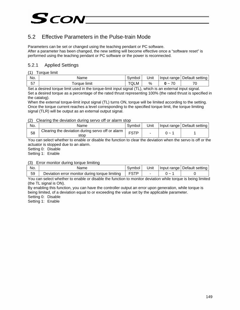
149
5.2 Effective Parameters in the Pulse-train Mode Parameters can be set or changed using the teaching pendant or PC software. After a parameter has been changed, the new setting will become effective once a “software reset” is performed using the teaching pendant or PC software or the power is reconnected. 5.2.1 Applied Settings (1) Torque limit No. Name Symbol Unit Input range Default setting57 Torque limit TQLM % 0 ~ 70 70
Set a desired torque limit used in the torque-limit input signal (TL), which is an external input signal. Set a desired torque as a percentage of the rated thrust representing 100% (the rated thrust is specified in the catalog). When the external torque-limit input signal (TL) turns ON, torque will be limited according to the setting. Once the torque current reaches a level corresponding to the specified torque limit, the torque limiting signal (TLR) will be output as an external output signal. (2) Clearing the deviation during servo off or alarm stop No. Name Symbol Unit Input range Default setting
58 Clearing the deviation during servo off or alarm stop FSTP - 0 ~ 1 1
You can select whether to enable or disable the function to clear the deviation when the servo is off or the actuator is stopped due to an alarm. Setting 0: Disable Setting 1: Enable (3) Error monitor during torque limiting No. Name Symbol Unit Input range Default setting59 Deviation error monitor during torque limiting FSTP - 0 ~ 1 0
You can select whether to enable or disable the function to monitor deviation while torque is being limited (the TL signal is ON). By enabling this function, you can have the controller output an error upon generation, while torque is being limited, of a deviation equal to or exceeding the value set by the applicable parameter. Setting 0: Disable Setting 1: Enable
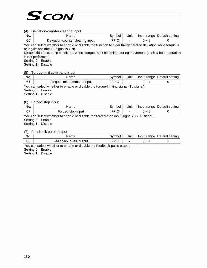
150
(4) Deviation-counter clearing input No. Name Symbol Unit Input range Default setting60 Deviation-counter clearing input FPIO - 0 ~ 1 0
You can select whether to enable or disable the function to clear the generated deviation while torque is being limited (the TL signal is ON). Disable this function in conditions where torque must be limited during movement (push & hold operation is not performed). Setting 0: Enable Setting 1: Disable (5) Torque-limit command input No. Name Symbol Unit Input range Default setting61 Torque-limit command input FPIO - 0 ~ 1 0
You can select whether to enable or disable the torque-limiting signal (TL signal). Setting 0: Enable Setting 1: Disable (6) Forced stop input No. Name Symbol Unit Input range Default setting67 Forced stop input FPIO - 0 ~ 1 0
You can select whether to enable or disable the forced-stop input signal (CSTP signal). Setting 0: Enable Setting 1: Disable (7) Feedback pulse output No. Name Symbol Unit Input range Default setting68 Feedback pulse output FPIO - 0 ~ 1 1
You can select whether to enable or disable the feedback pulse output. Setting 0: Enable Setting 1: Disable

151
(8) Feedback pulse pattern No. Name Symbol Unit Input range Default setting69 Feedback pulse pattern FBPT - 0 ~ 1 0
You can set a desired pattern in which to output feedback pulses. (9) Feedback-pulse pattern polarity No. Name Symbol Unit Input range Default setting70 Feedback-pulse pattern polarity FBPT - 0 ~ 1 0
You can set a desired polarity to be applied to the feedback pulse pattern. Setting 0: Positive logic Setting 1: Negative logic
Command pulse-train pattern Input terminal Forward Reverse
Neg
ativ
e lo
gic
Posi
tive
logi
c
Forward pulse train
Reverse pulse train A forward pulse train indicates motor revolutions in the forward direction, while a reverse pulse train indicates motor revolutions in the negative direction.
Pulse train
Sign
Command pulses indicate motor revolutions, while a command sign indicates a rotating direction.
Phase-A/B pulse train
Phase-A/B x4 pulses with a 90° phase difference indicate motor revolutions and a rotating direction.
Forward pulse train
Reverse pulse train
Pulse train
Sign
Phase-A/B pulse train
Setting

152
Appendix
* Appendix
1. Actuator Specification List
*1: The figure in the elongated circle indicates the maximum speed for each stroke. *2: The loading capacity is calculated by assuming actuator operation at the rated acceleration.
Model Stroke (mm), maximum speed (mm/sec) *1 Loading capacity *2 Rated acceleration
Horizontal Vertical Horizontal Vertical
(Slid
er ty
pe)
(Rod
type
) (A
rm/fl
at ty
pe)

153
Appendix
*1: The figure in the elongated circle indicates the maximum speed for each stroke. *2: The loading capacity is calculated by assuming actuator operation at the rated acceleration.
500°/sec
500°/sec
500°/sec
Model Stroke (mm), maximum speed (mm/sec) *1
Loading capacity *2 Rated acceleration
Horizontal Vertical Horizontal Vertical
(Rot
ary
type
) (S
lider
type
) (D
ustp
roof
/spl
ash-
proo
f typ
e)

154
Appendix
*1: The figure in the elongated circle indicates the maximum speed for each stroke. *2: The loading capacity is calculated by assuming actuator operation at the rated acceleration.
Model Stroke (mm), maximum speed (mm/sec) *1
Loading capacity *2 Rated acceleration
Horizontal Vertical Horizontal Vertical
(Slid
er ty
pe)
(Rod
type
) (F
lat t
ype)
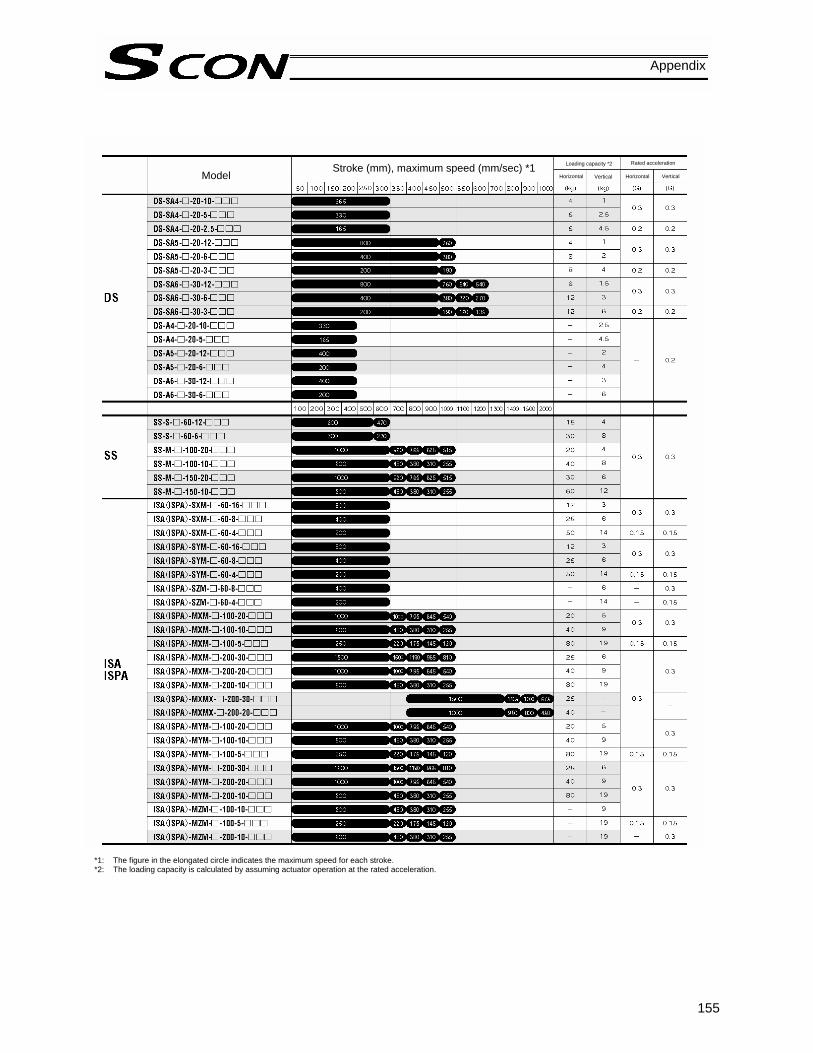
155
Appendix
*1: The figure in the elongated circle indicates the maximum speed for each stroke. *2: The loading capacity is calculated by assuming actuator operation at the rated acceleration.
Model Stroke (mm), maximum speed (mm/sec) *1 Loading capacity *2 Rated acceleration
Horizontal Vertical Horizontal Vertical
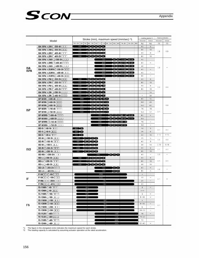
156
Appendix
*1: The figure in the elongated circle indicates the maximum speed for each stroke. *2: The loading capacity is calculated by assuming actuator operation at the rated acceleration.
Model Stroke (mm), maximum speed (mm/sec) *1 Loading capacity *2 Rated acceleration
Horizontal Vertical Horizontal Vertical

157
Appendix
2. Battery Backup Function The SCON controller uses the following battery: • Absolute-encoder backup battery
This battery is used to retain the rotation data of the absolute encoder, so that the motor rotation data will be retained, and thus can be updated, after the controller power has been cut off. Each controller to which an absolute type actuator is connected is shipped with this backup battery. The following pages describe the details of this function.

158
Appendix
2.1 Absolute-encoder Backup Battery If the SCON controller is to drive/control an absolute type actuator, an absolute-encoder backup battery must be installed in the controller. An absolute encoder is designed to retain rotation data and detect rotations using the power supplied from the absolute-encoder backup battery, even when the controller’s control power is not supplied. This allows the controller to resume positioning control immediately after the controller power is restored, without performing home return. <Backup Time> The recommended replacement interval for the absolute-encoder backup battery is two years. This may be a little misleading. It means that if the battery is left at an ambient temperature of 40°C, it will retain the stored data for two years. In normal operating conditions, the battery can retain data for a longer period. As a guide, the battery will last for around four years if the controller is used at an ambient temperature of 40°C with the controller powered up 50% of the time. <Battery Replacement> To replace the absolute-encoder backup battery, unplug the battery connector at the bottom of the controller and replace the battery in the battery holder. It is recommended that the battery be replaced regularly in accordance with the frequency/duration of usage. The battery must be replaced as soon as the controller’s battery voltage monitor function generates a battery voltage low alarm. After an alarm is detected, a battery error will occur in approx. 10 days at an ambient temperature of 20°C if the power is supplied to the controller continuously. Once a battery error occurs, operations can no longer be performed unless the battery is replaced and an absolute reset is performed. If the controller is not operated, the above period should be reduced to 70% at 20°C or to 60% at 40°C. The controller is designed so that the data will not be lost for at least 15 minutes without a battery if the controller is not detecting a battery error. Remember to complete the battery replacement within 15 minutes (i.e., the controller should not be without a battery for more than 15 minutes). The absolute-encoder backup battery is replaced differently depending on whether a battery error has generated or not. If an error has not been detected, only the battery needs to be replaced and an absolute reset is not required. If an error has been detected, an absolute reset will be required.

159
Appendix
The table below lists the absolute-encoder backup specifications. List of absolute-encoder backup functions Battery model AB-5 (by IAI) Battery voltage 3.6 V Current capacity 2000 mAH Detection voltage for battery voltage low alarm (Typical) 3.1 V, 3.0 V ~ 3.2 V
Detection voltage for battery voltage low error (Typical) 2.5V, 2.3V ~ 2.7V
Time after alarm detection until error detection (reference)
10 days if the controller is operated continuously at 20°C, or 7 days if no power is supplied 10 days if the controller is operated continuously at 40°C, or 2.5 days if no power is supplied
Minimum data retention voltage 2.7 V min. (Varies depending on the encoder characteristics.) Time after alarm detection until data loss (reference)
With an absolute encoder, absolute reset must always be performed once an error has been detected.
Data assurance limit during battery replacement
15 minutes (Maximum time during which data can be retained without any battery in the battery holder)
Data is retained by the super capacitor in the absolute brake unit.
Temperature 40°C, power supplied 0% of the time 2 years
Reference battery replacement interval Temperature 40°C, power
supplied 50% of the time 4 years

160
Appendix
3. Parameter Settings 3.1 Parameter Table The parameters are classified into the following five types based on what they are for: Category: a: Parameter relating to the actuator stroke range
b: Parameter relating to the actuator operating characteristics c: Parameter relating to the external interface d: Servo gain adjustment e: Parameters relating to controller monitoring
No. Category Name Unit Default factory setting 1 a Zone boundary 1+ mm Effective actuator length 2 a Zone boundary 1– mm Effective actuator length 3 a Soft limit+ mm Effective actuator length 4 a Soft limit– mm Effective actuator length
5 a Home return direction [0: Reverse / 1: Forward] - (In accordance with the specification at the time of order)
6 b Push & hold stop judgment period msec 255
7 d Servo gain number - Set individually in accordance with the actuator characteristics.
8 b Default speed mm/sec Set individually in accordance with the actuator characteristics.
9 b Default acceleration/deceleration G Set individually in accordance with the actuator characteristics.
10 b Default positioning band (in-position) mm 0.10
13 b Current-limiting value during home return % Set individually in accordance with the actuator characteristics.
14 b Dynamic brake [0: Disable / 1: Enable] - 0 [Disable]
15 c Pause input disable selection [0: Enable / 1: Disable] - 0 [Enable]
16 c SIO communication speed bps 38400
17 c Minimum delay time for slave transmitter activation msec 5
18 b Home-sensor input polarity - (In accordance with the specification at the time of order)19 b Overrun-sensor input polarity - (In accordance with the specification at the time of order)20 b Creep-sensor input polarity - (In accordance with the specification at the time of order)
21 c Servo ON input disable selection [0: Enable / 1: Disable] - 0 [Enable]
22 a Home return offset mm Set individually in accordance with the actuator characteristics.
23 a Zone boundary 2+ mm Effective actuator length 24 a Zone boundary 2– mm Effective actuator length 25 c PIO pattern selection - 0 [Standard type] 26 b PIO jog speed mm/sec 100
27 c Movement command type [0: Level / 1: Edge] - 0 [Level]
31 d Speed loop proportional gain - Set individually in accordance with the actuator characteristics.
32 d Speed loop integral gain - Set individually in accordance with the actuator characteristics.
33 d Torque filter time constant - Set individually in accordance with the actuator characteristics.
34 b Push speed mm/sec Set individually in accordance with the actuator characteristics.
35 b Safety speed mm/sec 100 36 b Automatic servo-off delay time 1 sec 0 37 b Automatic servo-off delay time 2 sec 0 38 b Automatic servo-off delay time 3 sec 0

161
Appendix
No. Category Name Unit Default factory setting
39 c Output mode of position complete signal [0: PEND / 1: INP] - 0 [PEND]
40 c Home-return input disable selection [0: Enable / 1: Disable] - 0 [Enable]
41 c Operating-mode input disable selection [0: Enable / 1: Disable] - 0 [Enable]
42 b Enable function [0: Enable/1: Disable] - 1 [Disable] 45 c Silent interval multiplier time 0 [Do not apply multiplier] 46 b Speed override % 100 47 b PIO jog speed 2 mm/sec 100 48 b PIO inching distance mm 0.1 49 b PIO inching distance 2 mm 0.1 50 b Load output judgment time msec 0 52 b Default acceleration/deceleration mode - 0 [Trapezoid] 53 b Default standstill mode - 0 [Complete stop]
54 d Current-control band number - Set individually in accordance with the actuator characteristics.
55 b Position-command primary filter time constant msec 0
56 b S-motion ratio setting % 0
72 e Timer period for emergency-stop relay fusing monitor msec 0
73 e Encoder voltage level - (In accordance with the specification at the time of order)
74 e PIO power monitor [0: Enable / 1: Disable] - 0 [Enable]
75 e Electromagnetic-brake power monitor [0: Disable / 1: Enable] - 0 [Disable]
(Note) The numbers are displayed in the PC software, but not on the teaching pendant. Skipped
numbers are not used and therefore omitted. The classification codes are provided for the sake of convenience and are not displayed either in the PC software or on the teaching pendant.
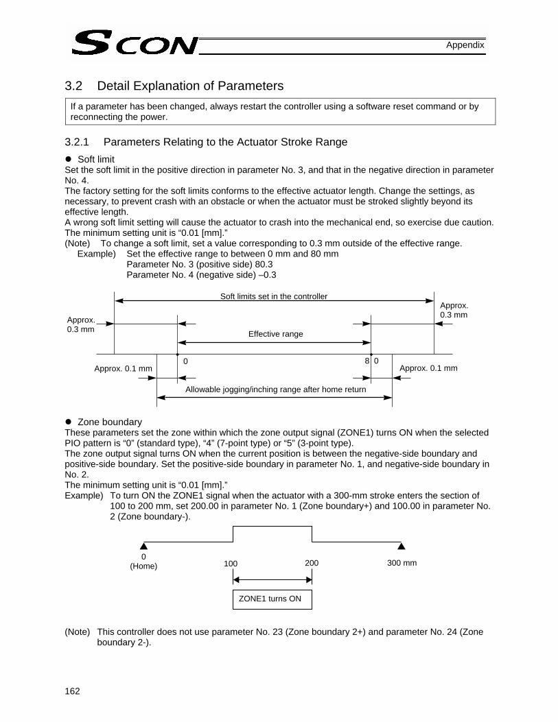
162
Appendix
3.2 Detail Explanation of Parameters
If a parameter has been changed, always restart the controller using a software reset command or by reconnecting the power.
3.2.1 Parameters Relating to the Actuator Stroke Range
Soft limit Set the soft limit in the positive direction in parameter No. 3, and that in the negative direction in parameter No. 4. The factory setting for the soft limits conforms to the effective actuator length. Change the settings, as necessary, to prevent crash with an obstacle or when the actuator must be stroked slightly beyond its effective length. A wrong soft limit setting will cause the actuator to crash into the mechanical end, so exercise due caution. The minimum setting unit is “0.01 [mm].” (Note) To change a soft limit, set a value corresponding to 0.3 mm outside of the effective range.
Example) Set the effective range to between 0 mm and 80 mm Parameter No. 3 (positive side) 80.3 Parameter No. 4 (negative side) –0.3
Zone boundary These parameters set the zone within which the zone output signal (ZONE1) turns ON when the selected PIO pattern is “0” (standard type), “4” (7-point type) or “5” (3-point type). The zone output signal turns ON when the current position is between the negative-side boundary and positive-side boundary. Set the positive-side boundary in parameter No. 1, and negative-side boundary in No. 2. The minimum setting unit is “0.01 [mm].” Example) To turn ON the ZONE1 signal when the actuator with a 300-mm stroke enters the section of
100 to 200 mm, set 200.00 in parameter No. 1 (Zone boundary+) and 100.00 in parameter No. 2 (Zone boundary-).
(Note) This controller does not use parameter No. 23 (Zone boundary 2+) and parameter No. 24 (Zone
boundary 2-).
Soft limits set in the controllerApprox. 0.3 mm
Effective range
Allowable jogging/inching range after home return
8 0 Approx. 0.1 mm Approx. 0.1 mm
0
Approx. 0.3 mm
0 (Home)
ZONE1 turns ON
100 200 300 mm
163
Appendix
Home return direction
Unless specified by the user, the home return direction is set to the motor direction at the factory. Should a need arise to change the home direction after the actuator has been assembled into your system, reverse the setting in parameter No. 5 between “0” and “1.” If necessary, also change the home return offset, soft limit and excited-phase signal detection direction parameters.
Caution: The home direction cannot be reversed for a rod-type actuator.
Home return offset The controller is shipped from the factory with an optimal value set in parameter No. 22, so the distance from each mechanical end to the home becomes uniform. The minimum setting unit is “0.01 [mm].” The home return offset can be adjusted in the following conditions: [1] Want to align the actuator home and the system’s mechanical home after the actuator has been
assembled into the system [2] Want to set a new home after reversing the factory-set home direction [3] Want to eliminate a slight deviation generated after replacing the actuator
Caution: If the home return offset has been changed, the soft limit parameters must also be adjusted accordingly.
164
Appendix
3.2.2 Parameters Relating to the Actuator Operating Characteristics
PIO jog speed When the selected PIO pattern is “1” (teaching type), this parameter defines the jog speed to be applied when jog input commands are received from the PLC. The factory setting is “100 [mm/sec].” Set an appropriate value in parameter No. 26 in accordance with the purpose of use. The maximum speed is limited to “250 [mm/sec].” (Note) Parameter No. 47 (PIO jog speed 2) is not used for this controller.
PIO inching distance When the selected PIO pattern is “1” (teaching type), this parameter defines the inching distance to be applied when inching input commands are received from the PLC. The factory setting is “0.1 [mm].” Set an appropriate value in parameter No. 48 in accordance with the purpose of use. The maximum limit is limited to “1 [mm].” (Note) Parameter No. 49 (PIO inching distance 2) is not used for this controller.
Default speed The factory setting is the rated speed of the actuator. When a target position is set in an unregistered position table, the setting in this parameter will be used as the speed data for the applicable position number. To reduce the default speed from the rated speed, change the setting in parameter No. 8.
Default acceleration/deceleration The factory setting is the rated acceleration/deceleration of the actuator. This value is treated as the acceleration/deceleration data corresponding to the applicable position number when a target position has been written to the unregistered position table. To reduce the default acceleration/deceleration from the rated acceleration/deceleration, change the setting in parameter No. 9.
Default positioning band (in-position) The factory setting is “0.10 [mm].” This value is treated as the positioning band data corresponding to the applicable position number when a target position has been written to the unregistered position table. Increasing the default positioning band will allow the position complete signal to be output early. Change the setting in parameter No. 10, as necessary.

165
Appendix
Default acceleration/deceleration mode
This value is treated as the data in the “Acceleration/deceleration mode” field corresponding to the applicable position number when a target position has been written to the unregistered position table. The factory setting is “0 [Trapezoid]. To change the default acceleration/deceleration pattern, set an applicable value in parameter No. 52 as shown below. Setting Trapezoid pattern 0 Primary delay filter 1 S-motion 2
Current-limiting value during home return
The factory setting conforms to the standard specification of the actuator. Increasing this setting will increase the home return torque. This setting need not be changed in normal conditions of use. However, if an increased slide resistance causes the home return to complete before the correct position depending on the affixing method, load condition or other factor when the actuator is used in a vertical application, the value set in parameter No. 13 must be increased. Please contact IAI.
Speed override Use this parameter when moving the actuator at a slower speed to prevent danger when the system is initially started for test operation. When move commands are issued from the PLC, the moving speed set in the “Speed” field of the position table can be overridden by the value set by parameter No. 46. Actual moving speed = [Speed set in the position table] x [Value of parameter No. 46] ÷ 100 Example) Value in the “Speed” field of the position table 500 (mm/s) Value of parameter No. 46 20 (%) Under the above settings, the actual moving speed becomes 100 mm/s. The minimum setting unit is “1 [%],” while the input range is “1 to 100 [%].” The factory setting is “100 [%].” (Note) This parameter is ignored for move commands from the PC and teaching pendant.
Safety speed This parameter defines the feed speed to be applied during manual operation. The factory setting is “100 [mm/sec].” To change this speed, set an optimal value in parameter No. 35. Take note that the maximum speed is limited to “250 [mm/s]” and that you should set a speed not exceeding this value.

166
Appendix
Move command
Servo status
Actuator movement
Servo on
Automatic servo-off mode (A green LED blinks.)
Target position T: Delay time (seconds) after positioning is completed until the servo turns off
Automatic servo-off delay time
This parameter defines the delay time after the positioning is completed until the servo turns off automatically, when the “Standstill mode” field of the position table is set to “1,” “2” or “3” (automatic servo-off control enabled) or parameter No. 53 (Default standstill mode) is set to “1,” “2” or “3”(automatic servo-off control enabled). Meaning of settings: 1: T becomes the value set by parameter No. 36.
2: T becomes the value set by parameter No. 37. 3: T becomes the value set by parameter No. 38.
The factory setting is “0 [sec].”
Default standstill mode [1] If the PIO pattern is 0, 1, 2, 3 or 4, the automatic servo-off mode can be selected to save current
consumption when the actuator is standing by for a long time after completing the home return effected by the HOME input signal.
[2] If the PIO pattern is 5, this value is treated as the setting in the “Standstill mode” field corresponding to the applicable position number when a target position has been written to the unregistered position table.
A value of “1,” “2” or “3” must be set in parameter No. 53 in order to enable the automatic servo-off function.
The factory setting is “0 [Disable].”
Setting All power-saving modes are disabled. 0 Automatic servo-off mode. The delay time is defined by parameter No. 36. 1 Automatic servo-off mode. The delay time is defined by parameter No. 37. 2 Automatic servo-off mode. The delay time is defined by parameter No. 38. 3
Automatic servo-off mode
After positioning is completed, the servo will turn off automatically upon elapse of a specified time. (Since no holding current flows, power consumption will decrease.) When the next movement command is received from the PLC, the servo will turn on and the actuator will start moving. Refer to the above timing chart.
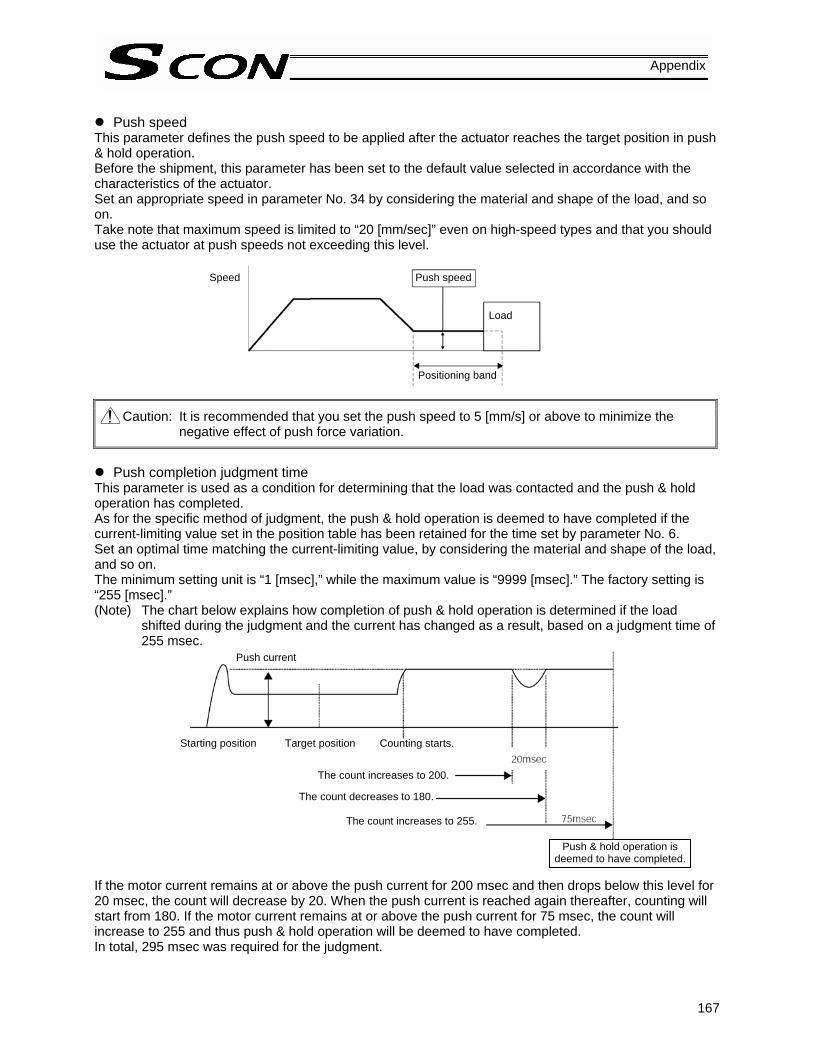
167
Appendix
Push speed
This parameter defines the push speed to be applied after the actuator reaches the target position in push & hold operation. Before the shipment, this parameter has been set to the default value selected in accordance with the characteristics of the actuator. Set an appropriate speed in parameter No. 34 by considering the material and shape of the load, and so on. Take note that maximum speed is limited to “20 [mm/sec]” even on high-speed types and that you should use the actuator at push speeds not exceeding this level.
Caution: It is recommended that you set the push speed to 5 [mm/s] or above to minimize the negative effect of push force variation.
Push completion judgment time
This parameter is used as a condition for determining that the load was contacted and the push & hold operation has completed. As for the specific method of judgment, the push & hold operation is deemed to have completed if the current-limiting value set in the position table has been retained for the time set by parameter No. 6. Set an optimal time matching the current-limiting value, by considering the material and shape of the load, and so on. The minimum setting unit is “1 [msec],” while the maximum value is “9999 [msec].” The factory setting is “255 [msec].” (Note) The chart below explains how completion of push & hold operation is determined if the load
shifted during the judgment and the current has changed as a result, based on a judgment time of 255 msec.
If the motor current remains at or above the push current for 200 msec and then drops below this level for 20 msec, the count will decrease by 20. When the push current is reached again thereafter, counting will start from 180. If the motor current remains at or above the push current for 75 msec, the count will increase to 255 and thus push & hold operation will be deemed to have completed. In total, 295 msec was required for the judgment.
Speed Push speed
Load
Positioning band
Push current
Starting position Target position Counting starts.
The count increases to 200. The count decreases to 180.
The count increases to 255.
Push & hold operation is deemed to have completed.

168
Appendix
Enable function
Whether to enable or disable the deadman switch function on an ANSI-type teaching pendant is defined by parameter No. 42. * An ANSI-type teaching pendant will be developed in the future. Setting Enable (Use) 0 Disable (Do not use) 1 The factory setting is “1 [Disable].”
Polarity of home check sensor input The home check sensor is not included in the standard specification, but it can be installed as an option. Normally this parameter need not be changed, but if the customer wishes to change the mode after the shipment, change the value of Parameter No. 18. Definition of settings: 0 (Standard specification without home check sensor)
1 (Use the home check sensor based on contact-a sensor polarity) 2 (Use the home check sensor based on contact-b sensor polarity)

169
Appendix
Overrun-sensor input polarity
The overtravel detection sensor is not included in the standard specification, but it can be installed as an option. This parameter is set properly prior to the shipment according to the customer’s specification and thus normally it need not be changed, but if the customer wishes to change the mode after the shipment, change the value of parameter No. 19. Definition of settings: 0 (Standard specification without sensor)
1 (Use the overtravel detection sensor based on contact-a sensor polarity) 2 (Use the overtravel detection sensor based on contact-b sensor polarity)
Creep-sensor input polarity
The travel speed of home return is normally set to a low level, or 20 mm/s to be specific. Therefore, an actuator with a long stroke will take a longer time to complete home return if the actuator was away from the home when the power was cut off. To save time in this situation, an optional creep sensor is available. The actuator moves at the creep speed (100 mm/s or below) until a creep sensor signal is detected, upon which the actuator will decelerate to the home return speed (20 mm/s). This parameter is set properly prior to the shipment according to the customer’s specification and thus normally it need not be changed, but if the customer wishes to change the mode after the shipment, change the value of parameter No. 20. Definition of settings: 0 (Standard specification without sensor)
1 (Creep sensor used based on contact-a sensor polarity) 2 (Creep sensor used based on contact-b sensor polarity)
Dynamic brake
This parameter defines whether the dynamic brake is enabled or disabled while the actuator is at standstill. The factory setting is “1 (Enable).” Normally this parameter need not be changed, but there are situations where the actuator with a short ball screw lead does not move smoothly, such as when the actuator is moved by hand with the servo turned off. In these situations, changing the value of parameter No. 14 to “0 (Disable)” will release the dynamic brake and allow the actuator to move more smoothly.
Caution: Before returning to normal operation, be sure to reset this parameter to “1 (Enable).”
Mechanical end
Home return speed
Creep sensor
Creep speed
Position at which the power is input
The actuator starts to decelerate upon detection of a creep sensor signal.

170
Appendix
Position-command primary filter time constant
Parameter No. 55 defines the delay to be applied when “1 [Primary delay filter]” is set in the “Acceleration/deceleration mode” field of the position table. The setting unit is 0.1 mm, while the setting range is 0.0 to 100.00. The factory setting is “0” [msec]. * The primary delay filter is disabled when “0” is set.
The greater the value set in this parameter, the longer the delay becomes.
S-motion ratio setting Parameter No. 56 defines the S-motion level to be applied when “2 [S-motion]” is set in the “Acceleration/deceleration mode” field of the position table. The setting unit is %, while the setting range is 0.0 to 100. The factory setting is “0” [%]. * The S-motion function is disabled when “0” is set.
The greater the value set in this parameter, the closer the acceleration/deceleration curb becomes to the letter “S.” (The graph below assumes an S-motion ratio of 100%.)
Load-output judgment time This parameter is not used with this controller.
Speed
Speed
Time
Time

171
Appendix
3.2.3 Parameters Relating to the External Interface
PIO pattern selection Select the PIO operation pattern in parameter No. 25. This setting forms the basis of operation, so be sure to set this parameter at the beginning. The factory setting is “0 [Standard type].” Parameter No.
25 setting Feature of PIO pattern
0 Standard type A basic type supporting 64 positioning points and two zone outputs. * How to set zone boundaries within which to output a zone signal: Zone boundaries are set using parameter Nos. 1 and 2 for one zone output, and in the position table for another zone output.
1 Teaching type In this type, 64 positioning points and one zone output (boundaries are set in the position table) are supported. In addition to the normal positioning mode, the user can also select the teaching mode in which the actuator can be jogged via commands from a PLC and the current actuator position can be written to a specified position. (Note 1) Jog commands from a PLC are also accepted in the positioning mode. (Note 2) Positions can be rewritten by approximately 100,000 times.
2 256-point positioning type The number of positioning points is increased to 256, so only one zone output is available (boundaries are set in the position table).
3 512-point positioning type The number of positioning points is increased to 512, so no zone output is available.
4 7-point type The number of positioning points is limited to seven to offer separate direct command inputs and movement complete outputs for respective positions. PLC ladder sequence circuits can be designed easily.
5 3-point type Use of the controller as an air cylinder is assumed in this type. Movement complete output signals function differently in this type, compared to the 7-point type. Specifically, the signal functions not only to “indicate movement complete,” but also to “detect a position” in the same manner as auto-switches of an air cylinder.
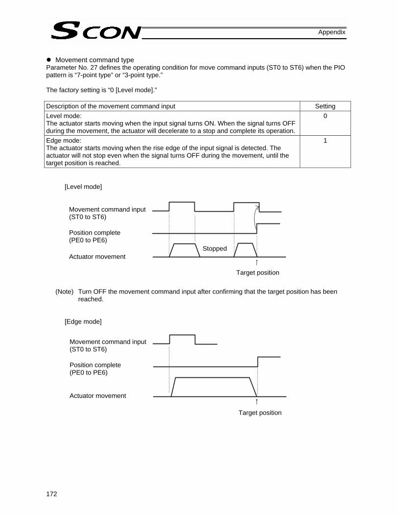
172
Appendix
Movement command type
Parameter No. 27 defines the operating condition for move command inputs (ST0 to ST6) when the PIO pattern is “7-point type” or “3-point type.” The factory setting is “0 [Level mode].” Description of the movement command input Setting Level mode: The actuator starts moving when the input signal turns ON. When the signal turns OFF during the movement, the actuator will decelerate to a stop and complete its operation.
0
Edge mode: The actuator starts moving when the rise edge of the input signal is detected. The actuator will not stop even when the signal turns OFF during the movement, until the target position is reached.
1
[Level mode]
(Note) Turn OFF the movement command input after confirming that the target position has been reached.
[Edge mode]
Movement command input (ST0 to ST6) Position complete (PE0 to PE6) Actuator movement
Stopped
Target position
Movement command input (ST0 to ST6) Position complete (PE0 to PE6)
Actuator movement
Target position

173
Appendix
Pause input disable selection
Parameter No. 15 defines whether the pause input signal is disabled or enabled. Setting
Enable (use) 0 Disable (do not use) the signal 1 The factory setting is “0 [Enable].”
Servo ON input disable selection Parameter No. 21 defines whether the servo ON input signal is disabled or enabled.
Setting Enable (use) 0 Disable (do not use) 1 The factory setting is “0 [Enable].”
Home-return input disable selection Parameter No. 40 defines whether the home-return input signal is disabled or enabled.
Setting Enable (use) 0 Disable (do not use) 1 The factory setting is “0 [Enable].”
Operating-mode input disable selection Parameter No. 41 defines whether the operating-mode input signal is disabled or enabled.
Setting Enable (use) 0 Disable (do not use) 1 The factory setting is “0 [Enable].”

174
Appendix
Output mode of position complete signal
This parameter is effective when any PIO pattern other than “5” [3-point type] is selected. It defines the status of completed position number signals [PM1 to PM256], movement complete signals at respective positions [PE0 to PE6] and position complete signal [PEND] to be applied if the servo turns off or “position deviation” occurs while the actuator is standing still after completing positioning. The following two conditions can be considered: [1] The position has deviated, due to external force and while the servo was on, beyond the value set in
the “Positioning band” field of the position table. [2] The position has deviated, due to external force and while the servo was off, beyond the value set in
the “Positioning band” field of the position table. This parameter is provided to permit flexible specification of how the “position complete status” is monitored in accordance with the characteristics of the system or sequence circuit on the PLC side. The ON/OFF status of each position complete signal is controlled as follows in accordance with the setting of parameter No. 39. Setting of parameter No. 39
Definition of completed position number signals [PM1 to PM256], movement complete signals at respective positions [PE0 to PE6] and position complete signal [PEND]
0 [PEND] [1] The servo is on The signal remains ON even after the current position has exited the range set by the “Positioning band” field of the position table, with respect to the target position. [2] The servo is off The signal is OFF unconditionally regardless of the current position.
1 [INP] Regardless of the servo on/off status, the signal turns ON if the current position is within the range set by the “Positioning band” field of the position table, with respect to the target position, and turns OFF if the current position is outside this range. * In this mode, the applicable signals are used as limit switches.
The factory setting is “0 [PEND].”
175
Appendix
SIO communication speed
This parameter is used for controllers of serial communication type. Set the communication speed to be used when the control is performed via serial communication using the PLC’s communication module. Set an appropriate value in parameter No. 16 in accordance with the specification of the communication module. One of 9600, 19200, 38400, 115200 and 230400 bps can be selected as the communication speed. The factory setting is “38400 [bps].”
Minimum delay time for slave transmitter activation This parameter is used for controllers of serial communication type. This parameter defines the minimum delay until the controller’s transmitter will be activated after completion of command reception, when serial communication is performed using the PLC’s communication module. The factory setting is “5 [msec],” but other necessary delay time must be set in parameter No. 17 if the specification of the communication module exceeds 5 msec.
Silent interval multiplier It is applied to controllers of RS485 serial communication type. If specified, this parameter defines the multiplier to be applied to the silent interval time for delimiter judgment in the RTU mode. The default setting is the communication time corresponding to 3.5 characters in accordance with the Modbus specification. This setting need not be changed for normal operations performed with a PC or teaching pendant. If the scan time of the PLC is not optimal and the character transmission interval exceeds the silent interval, the silent interval time can be extended using parameter No. 45. The minimum setting unit is “1 [time],” while the input range is “0 to 10.” If “0” is set, no multiplier is applied.

176
Appendix
3.2.4 Servo Gain Adjustment Before the shipment, the servo has been adjusted in accordance with the standard specification of the actuator. Accordingly, the servo settings need not be changed in normal conditions. Nonetheless, the parameters relating to servo adjustment are made accessible by the customer so that speedy actions can be taken in situations where vibration or noise occurs due to the affixing method of the actuator, load condition, or the like. In particular, custom types (having a longer ball screw lead or stroke than standard types) are more vulnerable to vibration and noise due to external conditions. In these circumstances, the following parameters must be changed. Contact IAI for details.
Servo gain number Parameter No. Unit Input range Default
7 5 rad/sec 0 ~ 31 5 This parameter determines the response when a position control loop is used. Increasing the set value improves the tracking performance with respect to the position command. However, increasing the parameter value excessively increases the chances of overshooting. If the set value is small, the tracking performance with respect to the position command drops and positioning takes a longer time.
Speed loop proportional gain Parameter No. Unit Input range Default
31 --- 1 ~ 27661 Set individually in accordance with the actuator characteristics.
This parameter determines the response when a speed control loop is used. Increasing the set value improves the tracking performance with respect to the speed command (i.e., servo rigidity increases). The greater the load inertia, the larger this parameter value should be. However, increasing the parameter value excessively makes the actuator more vulnerable to overshooting or shaking, leading to mechanical vibration.
Speed Set value is large (overshooting).
Set value is small.
Time
Speed Set value is large (overshooting).
Set value is small.
Time

177
Appendix
Speed loop integral gain
Parameter No. Unit Input range Default
32 --- 1 ~ 217270 Set individually in accordance with the actuator characteristics.
This parameter determines the response when a speed control loop is used. Increasing the set value lowers the response with respect to the speed command, while also decreasing the reactive force that generates upon load change. Decreasing the parameter value excessively makes the actuator more vulnerable to overshooting or shaking, leading to mechanical vibration. If the set value is small, the tracking performance with respect to the position command drops and positioning takes a longer time.
Torque filter time constant Parameter No. Unit Input range Default
33 --- 1 ~ 2500 Set individually in accordance with the actuator characteristics.
This parameter determines the filter time constant for torque commands. If the resonance frequency of the machine is smaller than the response frequency of the servo loop, the motor vibrates. This mechanical resonance can be suppressed by increasing the value set in this parameter. However, increasing the parameter value excessively may reduce the stability of control.
Current-control band number Parameter No. Unit Input range Default
54 --- 0 ~ 7 Set individually in accordance with the actuator characteristics.
This parameter sets the control band for PI current control. Normally this parameter need not be changed, so the customer is advised not to change the setting. If the parameter is changed carelessly, control safety may be adversely affected and a very dangerous situation may result. However, changing this parameter may be effective in certain situations, such as when the actuator generates resonance noise that can be suppressed by changing this parameter. Even in this case, the customer is advised to consult IAI and change the parameter according to the instruction given.
Speed
Set value is large
Set value is small. (overshooting).
Time

178
Appendix
Feed-forward gain
Parameter No. Unit Input range Default
71 --- 0 ~ 100 Set individually in accordance with the actuator characteristics.
This parameter sets the level of feed-forward gain to be applied to position control. Setting this parameter will increase the servo gain, thereby improving the response in operations based on a position control loop. Use this parameter if you wish to improve the response of your system having low mechanical rigidity or whose mechanical configuration is subject to a high load inertia ratio. As a guide, set a value between 10 and 50. Increasing the value set in this parameter will reduce the deviation and therefore improve the response. Take note, however, that setting a larger value may result in vibration or noise.

179
Appendix
3.2.5 Parameters Relating to Controller Monitoring
Timer period for emergency-stop relay fusing monitor The controller has a built-in emergency stop relay for cutting off the motor drive power, so fusing of this relay is detected. If the motor AC power is not cut off after elapse of the timer period set by this parameter following the cutoff of the driver power, the controller will recognize that the relay has been fused and generate an alarm. Normally this parameter need not be changed. If you have installed an additional drive-power cutoff relay, etc., with a timer and are using the relay with a timer period longer than the factory setting, however, the value of parameter No. 72 should be changed accordingly. The factory setting is “3,000” [msec]. If a value between 0 and 9 is set, fusing of the relay will not be detected.
Encoder voltage level To stabilize encoder detection signals, this parameter sets the voltage supplied to the encoder circuit to one of four levels in accordance with the encoder type and the length of the encoder relay cable. Normally this parameter need not be changed. If you have changed the length of the encoder relay cable supplied with the controller, however, the value of parameter No. 73 must be changed accordingly. If you wish to change this parameter, always consult IAI in advance. (If set inappropriately, this parameter may cause problems such as an encoder failure.)
PIO power monitor [0: Enable /1: Disable] A power monitor function is provided to prevent burning of the I/O board or breakdown of parts caused by an abnormal voltage of the 24-V PIO power supply. Although it is recommended to enable this function, it can be disabled in certain situations such as when making adjustments during trial operation. To disable the function, set parameter No. 74 to “1 [Disable].” The factory setting is “0 [Enable].” * If a fieldbus module (such as a CC-Link or DeviceNet module) is installed, the controller will not
perform PIO power monitor regardless of the setting of this parameter.
Electromagnetic-brake power monitor [0: Disable /1: Enable] A power monitor function is provided to prevent actuator malfunction or breakdown of parts caused by an abnormal voltage of the 24-V brake power supply when an actuator with brake is used. Normally this parameter need not be changed because it has been set properly prior to the shipment in accordance with the actuator, i.e., whether or not the actuator is equipped with a brake. If you have changed the original actuator specification, however, change the value of parameter No. 75 accordingly. The factory setting is “0 [Disable]” if the actuator has no brake, and “1 [Enable]” if the actuator is equipped with a brake.

180
Appendix
4. PC/Teaching Pendant Connection Method in Multi-axis Configurations
This section explains the method to permanently connect a PC/teaching pendant in configurations consisting of multiple axes, so that the PC/teaching pendant connector need not be removed/inserted each time. The connector is connected to a SIO converter, and the SIO converter sends/receives data to/from each controller via RS485 serial communication. The basic specifications are as follow: [1] Maximum number of connected axes: 16 [2] Maximum length of serial communication cable: 100 m or less [3] Terminal resistor: 220 Ω (Be sure to install a terminal resistor for the last axis to prevent the effect
of radiating noise.)
4.1 Connection Example
Caution: Do not connect the teaching pendant and PC at the same time. If both are connected at the same time, a communication error (message level) will occur.
Teaching pendant [RCM-T]
PC software (Optional)
RS232C cross cable (Provided by the user)
Components:
SIO converter (with built-in terminal resistor) <RCB-TU-SIO-A> Vertical type <RCB-TU-SIO-B> Horizontal type
Input power supply
Controller power supply
Terminal resistor R = 220 Ω
Controller link cable<CB-RCB-CTL002>
ADRS switch: 0
Controller 1
ADRS switch: 1
Controller 2
ADRS switch: n-1
Controller n
E-Con connector (AMP 4-1473562-4: housing color green)
E-Con connector (AMP 3-1473562-4: housing color orange)
Junction (AMP 5-1473574-4)
Green Green Green
(Note) External equipment communication cable <CB-RCA-SIO-***> cannot be used for connection to a PC.
RS232C type <RCM-101-MW> USB type <RCM-101-USB>

181
Appendix
4.2 Name and Function of Each Part of the SIO Converter This is a converter unit conforming to RS485/232C. [1] Power/emergency-stop terminal block (TB2)
EMG1, EMG2 Provide a contact output for the emergency-stop switch on the teaching pendant. EMG1 and EMG2 connect to the emergency-stop switch on the teaching pendant when the PORT switch is ON, or are shorted when the PORT switch is OFF. These terminals comprise an interlock with a safety circuit provided by the user.
24V Positive side of the 24-V power supply (power supply for the teaching pendant and conversion circuit)
0V Negative side of the 24-V power supply FG FG of the 24-V power supply
(Note) 0V connects to pin 7 (GND) in the controller’s communication connector.
Connection method Use a connection cable satisfying the following specifications:
Item Specification
Applicable wire size Single wire: ∅0.8 to 1.2 mm / Stranded: AWG size 20 to 18 (end is soldered) Stripped wire length 10 mm
[2] Link-connection terminal block (TB1) [1] Power/emergency-stop terminal block (TB2)
[6] Monitor LEDs
[3] D-sub, 9-pin connector [4] Mini DIN, 8-pin connector
[5] PORT switch
Used for continuity check Insert a flathead screwdriver with a bit size of approx. 2.6 mm.
Connection cable
[6] e-CON connector

182
Appendix
[2] Link-connection terminal block (TB1)
A connection port for linking the controller. “A” on the left side connects to pin 1 (SGA) in the controller’s communication connector. “B” on the right side connects to pin 2 (SGB) in the controller’s communication connector. (Note) Be sure to use twisted pair wires for the above two connections (SGA/SGB).
[3] D-sub, 9-pin connector
A connection port with the PC. [4] Mini DIN, 8-pin connector
A connection port with the teaching pendant. [5] PORT switch
A switch for enabling/disabling the teaching pendant. Set the switch to ON when a teaching pendant is used, or OFF when teaching pendant is not used.
[6] Monitor LEDs
LED1 --- Lit when the controller is transmitting LED2 --- Lit when the RS232 is transmitting
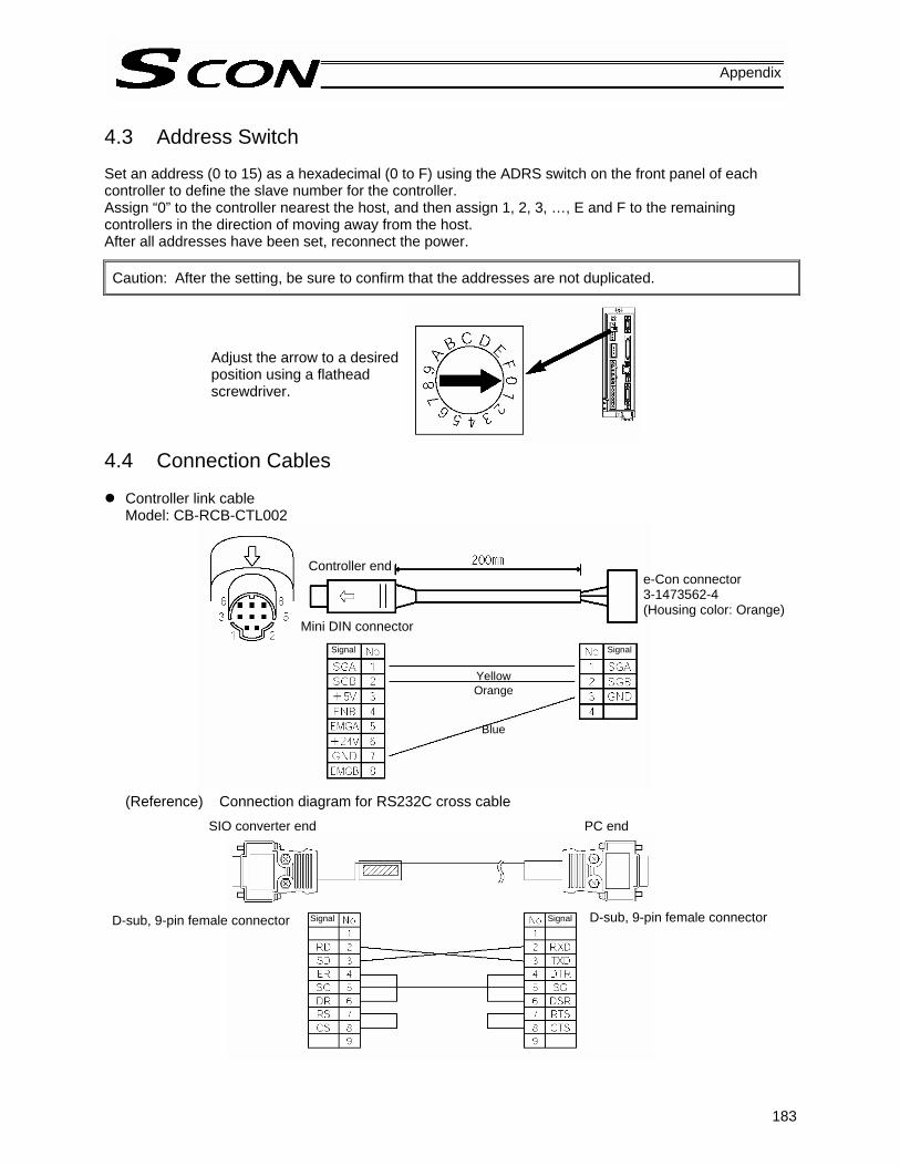
183
Appendix
4.3 Address Switch Set an address (0 to 15) as a hexadecimal (0 to F) using the ADRS switch on the front panel of each controller to define the slave number for the controller. Assign “0” to the controller nearest the host, and then assign 1, 2, 3, …, E and F to the remaining controllers in the direction of moving away from the host. After all addresses have been set, reconnect the power.
Caution: After the setting, be sure to confirm that the addresses are not duplicated.
4.4 Connection Cables
Controller link cable Model: CB-RCB-CTL002
(Reference) Connection diagram for RS232C cross cable
SIO converter end PC end
Adjust the arrow to a desired position using a flathead screwdriver.
D-sub, 9-pin female connector D-sub, 9-pin female connector
Controller end
Mini DIN connector
e-Con connector 3-1473562-4 (Housing color: Orange)
Yellow Orange
Blue
Signal Signal
Signal Signal

184
Appendix
4.5 Detail Connection Diagram (Note) The user must provide the two-paired shielded cable.
If cables other than the recommended brands are connected to [1] and [2], use those with a cable-sheath outer diameter of 1.35 to 1.60 mm.
Accessories (Optional): [1] Controller link cable CB-RCB-CTL002 (connector on both ends), length 200 mm [2] Four-way junction, made by AMP: 5-1473574-4 [3] e-Con connector, made by AMP: 4-1473562-4 (green) [4] Terminal resistor 220 Ω (with e-Con connector) Of the above, [2], [3] and [4] are provided for the same number as the controller link cables. Therefore, not all units are needed when multiple axes are used.
1 2
SIO converter
Two-paired shielded cable Recommended brand: Taiyo Electric Wire & Cable HK-SB/20276XL 2PX22AWG
Four-way junction (AMP: 5-1473574-4)
A
B
EMG2EMG1
24V0VFG
1
2
3
4
1
2
7
1
2
7
SGA
SGB
GND
Yellow
Orange
Blue
Yellow
Orange
Blue
Housing color: Green
Controller link cable CB-RCB-CTL002
e-Con connector (AMP: 4-1473562-4)
Controller 1 e-Con connector (AMP: 3-1473562-4)
Housing color: Orange
TB1
TB2
Controller 2
[B]
1
2
3
4
1
2
3
4
1
2
3
4
SGA
SGB
GND
[A]

185
Appendix
5. Troubleshooting 5.1 Action to Be Taken upon Occurrence of Problem
Upon occurrence of a problem, take an appropriate action according to the procedure below in order to ensure speedy recovery and prevent recurrence of the problem. a. Check the status indicator lamps.
SV (green) --- The servo is ON. ALM (orange) --- An alarm is present or the motor drive power is cut off. EMG (red) --- An emergency stop is actuated.
b. Check for error in the host controller. c. Check the voltage of the main power supply (control power, motor power). d. Check the voltage of the 24-VDC power supply for input/output signals as well as the 24-VDC power
supply for brake (if the actuator is equipped with a brake). e. Check for alarm.
Confirm the details of error on the PC or teaching pendant. f. Check the cables for connection error, disconnection or pinching.
Before performing a continuity check, turn off the power (to prevent a runaway actuator) and disconnect the cables (to prevent accidental power connection due to a sneak current path).
g. Check the I/O signals. h. Check the noise elimination measures (grounding, installation of surge killer, etc.). i. Review the events leading to the occurrence of problem, as well as the operating condition at the time
of occurrence. j. Check the serial numbers of the controller and actuator. k. Analyze the cause. l. Take action.
Please check items a through j before contacting IAI.
(Note 2) The *ALM output signal is a contact-b signal.
After the power is turned on, this signal remains ON while the controller is normal. It remains OFF while the power is cut off. It cannot be used as a contact-b interlock when the power is cut off.

186
Appendix
5.2 Alarm Level Classification Alarms are classified into two levels based on the corresponding symptoms.
Alarm level ALM lamp *ALM signal What happens when alarm generates How to reset
Operation cancellation Lit Output
The actuator decelerates to a stop and then the servo turns OFF.
Reset by the PC/teaching pendant.
Cold start Lit Output The actuator decelerates to a stop and then the servo turns OFF.
Reconnect the power.
Caution: Reset each alarm after identifying and removing the cause of the alarm. If the cause of the
alarm cannot be removed or the alarm still persists after the cause has been removed, contact IAI. If the same error occurs again after resetting the alarm, it means that the cause of the alarm still remains.

187
Appendix
5.3 Alarm Description Output Using PIO In PIO patterns 0 to 3 (64 to 512-point positioning type), alarm information can be output using the ports for completed position output signals (four bits of PM1 to PM8) so that when an alarm occurs, the nature of the alarm can be identified on the PLC side. Program the PLC so that whether a given output is a completed position number or alarm can be identified based on the status of the alarm output signal (*ALM). Bit assignment table for alarm description ( = OFF, = ON) ∗ALM PM8 PM4 PM2 PM1 Description: Code number in ( )
x x x x Normal Software reset during servo on (090)
PWRT signal detected during movement (092) PWRT signal detected before completion of home return (093)
Move command during servo off (080) Absolute position move command before completion of home return (083) Move command during home return (084) Position number error during movement (085) Position command data error (0A3) Deceleration command error (0A7)
PCB mismatch error (0F4) Parameter data error (0A1)
Position data error (0A2) Magnetic pole not confirmed (0B7)
Home sensor not detected (0BA) Home return timeout (0BE) Creep sensor not detected (0BF)
Excessive actual speed (0C0) Overrun detected (0C2)
Electromagnetic brake not released (0A5) Dynamic brake not released (0A6) Overcurrent (0C8) Overheating (0CA) Current-sensor offset adjustment error (0CB) Emergency stop relay fused (0CD) Control power-supply voltage low (0CE) 24-V I/O power-supply error (0CF)
Command counter overflow (0A4) Deviation overflow (0D8) Software stroke limit exceeded (0D9) Feedback pulse error (0DA) Out of push & hold operation range error (0DC)
Motor power-supply voltage excessive (0D2) Motor power-supply voltage low (0D3) Overload (0E0) Driver logic error (0F0)

188
Appendix
∗ALM PM8 PM4 PM2 PM1 Description: Code number in ( )
Encoder send error (0E4) Encoder receive error (0E5) Encoder count error (0E6) Open phase A/B/Z (0E7) Absolute encoder error detected 2 (0EE) Absolute encoder error detected 3 (0EF)
CPU error (0FA) FPGA error (0FB)
Nonvolatile memory write verification error (0F5) Nonvolatile memory write timeout (0F6) Damaged nonvolatile memory data (0F8)

189
Appendix
5.4 Alarm Description and Cause/Action (1) Operation-cancellation level alarms Code Error name Cause/Action 080 Move command
during servo off Cause: A move command was issued by numerical specification when
the servo was off. Action: Issue a command after confirming that the servo is on (SV or
PEND is “1”). 083 Numerical command
before completion of home return
Cause: An absolute position command was issued by numerical specification before home return was completed. (This does not present a problem in the position number specification mode.)
Action: Issue a move command by numerical specification after completing the home return operation and confirming that the complete signal (HEND) has turned ON.
084 Move command during home return
Cause: A move command was issued by numerical specification when home return was still in progress.
Action: Issue a move command by numerical specification after completing the home return operation and confirming that the complete signal (HEND) has turned ON.
085 Position number error during movement
Cause: A position number not yet registered in the position table was specified in the position number specification mode.
Action: Check the position table again. 090 Soft reset during
servo on Cause: A soft reset command was received when the servo was on. Action: Send a soft reset command to the controller after confirming that
the servo is off (SV is “0”).

190
Appendix
Code Error name Cause/Action 092 PWRT signal detected
during movement Cause: The current-position write signal (PWRT) was input in the
teaching mode while the actuator was jogging. Action: Input the PWRT signal after confirming that the jog button is not
pressed and the actuator is stopped (MOVE output signal is OFF).093 PWRT signal detected
before completion of home return
Cause: The current-position write signal (PWRT) was input in the teaching mode when home return was not yet completed.
Action: Input the HOME signal first to perform home return, and then input the PWRT signal after confirming that home return has completed (HEND output signal is ON).
0A1 Parameter data error Cause: The input range of parameter range data is not appropriate. (Example) This error occurs when the magnitude relationship of a
pair of range parameters is inappropriate, such as when the value of soft limit- is mistakenly set to 300 mm when the value of soft limit+ is 200.3 mm.
Action: Change the parameters to appropriate values. 0A2 Position data error Cause: [1] A move command was input when no target position was set in
the “Position” field. [2] The target position in the “Position” field exceeds a soft limit
setting. [3] An incremental target position was specified in the “Position”
field in the 3-point type. Action: [1] Set a target position first.
[2] Change the target position to a value inside the soft limit setting.
[3] Specify an absolute target position. 0A3 Position command
data error Cause: The speed or acceleration/deceleration specified by the numerical
command exceeds the maximum value that can be set. Action: Change the applicable setting to an appropriate value.
0A4 Command counter overflow
Cause: The number of input command pulses exceeded the range of -134217728 to +134217728 (H’F8000000 to H’07FFFFFF).
Action: Raise the electronic gear ratio to increase the unit travel distance. 0A5 Electromagnetic brake
not released Cause: The brake cannot be released when an electromagnetic brake is
equipped. Action: Check the 24-V electromagnetic-brake power supply.
0A6 Dynamic brake not released
Cause: The dynamic brake cannot be released when the servo is on due to noise, electrostatic, etc.
Action: Eliminate the noise or electrostatic. 0A7 Deceleration
command error If a position command is issued while the actuator is moving where the target position corresponding to the position number is located near a soft limit and the deceleration is also set low, the actuator may move past the soft limit. Cause: When the speed was changed during movement, the next move
command was not issued quick enough. Action: Quicken the speed change timing so that the actuator will not
overshoot the soft limit.
Deceleration starting position not resulting in soft limit overshoot If a command is issued here,
soft limit overshoot will occur.
Soft limit

191
Appendix
Code Error name Cause/Action 0B7 Magnetic pole not
confirmed This controller detects the magnetic-pole phase when the servo is turned on for the first time after turning on the power. This error indicates that a magnetic-pole phase cannot be detected after a specified period. Cause: [1] The connector of the motor relay cable is loose or its circuit is
open. [2] If the actuator is equipped with a brake, the brake cannot be
released. [3] The motor load increased due to application of external force. [4] The sliding distance of the actuator itself is high.
Action: [1] Check the wiring condition of the motor relay cable. [2] Check the wiring condition of the brake cable, and also turn
on/off the brake release switch to check if “click” sound is heard.
[3] Check the assembly condition of mechanical parts for any abnormality.
[4] If the load is normal, cut off the power and move the actuator by hand to check the sliding resistance.
If the actuator itself is suspected as the cause, contact IAI. 0BA Home sensor not
detected This error indicates that the actuator equipped with the home check sensor has not yet successfully completed the home return operation. Cause: [1] The load contacted any surrounding equipment or structure
during home return. [2] The slide resistance of the actuator is high in some location. [3] The home check sensor is not properly installed, faulty or
open. Action: If the load is not contacting any surrounding equipment or
structure, [2] or [3] is suspected. Please contact IAI. 0BE Home return timeout Cause: Home return does not complete after elapse of the time set by the
applicable manufacturer’s parameter following the start of home return operation. (This error does not occur in normal operations.)
Action: The controller and actuator combination is wrong, among others. Please contact IAI.
0BF Creep sensor not detected
This error indicates during home return operation using a creep sensor a home-sensor detection signal was output or mechanical end was reached before a creep sensor signal was detected (or the actuator cannot move due to an excessive load). Cause: [1] Signal is not detected because the creep sensor is not
installed in an appropriate position. [2] The cable is disconnected or the connector is not plugged in
properly. [3] The load is receiving an external force.
Action: [1] Readjust the sensor installation position. [2] Perform continuity check to see if the cable is disconnected.
Also check if the connector is plugged in properly. [3] Review the mechanisms around the load and prevent the load
from receiving any strong external force. If the cause cannot be specified, contact IAI.

192
Appendix
Code Error name Cause/Action 0C0 Excessive actual
speed Cause: The motor speed exceeded the maximum level set by the
applicable manufacturer’s parameter. Although this error does not occur in normal operations, it may occur if the load decreased before a servo error was detected and the actuator moved quickly as a result, which can be caused by various reasons including the following: [1] The slide resistance of the actuator is high in some location. [2] The load increased due to momentary application of external
force. Action: Check the assembly condition of mechanical parts for any
abnormality. If the actuator itself is suspected as the cause, please contact IAI.
0C2 Overrun sensor signal detected
This error indicates that a signal from the OT sensor installed at a mechanical end was detected.
Cause: [1] The actuator was moved by hand or received an external force while the servo was off (normal detection).
[2] The actuator was jogged in a condition where the home coordinates were not yet established and thus the soft stroke check did not function correctly (normal detection).
[3] The home position achieved by home return is not correct, or in the case of an absolute type controller the coordinates have shifted due to an inappropriate absolute reset position.
[4] The sensor characteristics do not match the setting of sensor parameter No. 19, or the sensor is wired wrongly.
[5] The controller and actuator combination is wrong, or the soft limit or screw lead set in the controller is not appropriate.
Action: If [1] or [2] is suspected, move the actuator in the opposite direction by hand. If this error occurred inside the effective stroke range, [3], [4] or [5] is a likely cause. Check the home position, parameter setting, wiring, etc. If the cause cannot be specified, contact IAI.
0C8 Overcurrent Cause: The output current in the power-supply circuit became abnormally high. This error should not occur in normal conditions of use. If it occurs, insulation of the motor coil may have deteriorated.
Action: Measure the resistance among motor wire phases U, V and W, as well as the insulation with respect to ground. to check if insulation has deteriorated. Contact IAI before performing the above measurement.
0CA Overheating This error indicates that the temperature around the power transistor in the controller is excessively high (95°C or above). Cause: [1] The ambient temperature is high.
[2] A faulty part inside the controller. Action: [1] Lower the ambient temperature.
[2] Add one or more regenerative boxes. 0CE Control power-supply
voltage low Cause: [1] The AC power-supply voltage is low.
[2] A faulty part inside the controller. Action: Check the input power-supply voltage.
If the voltage is normal, please contact IAI.
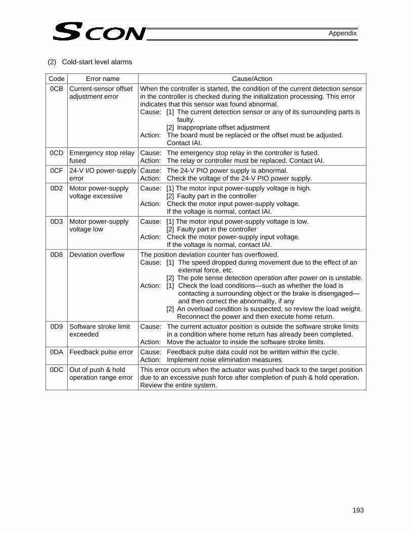
193
Appendix
(2) Cold-start level alarms Code Error name Cause/Action 0CB Current-sensor offset
adjustment error When the controller is started, the condition of the current detection sensor in the controller is checked during the initialization processing. This error indicates that this sensor was found abnormal. Cause: [1] The current detection sensor or any of its surrounding parts is
faulty. [2] Inappropriate offset adjustment
Action: The board must be replaced or the offset must be adjusted. Contact IAI.
0CD Emergency stop relay fused
Cause: The emergency stop relay in the controller is fused. Action: The relay or controller must be replaced. Contact IAI.
0CF 24-V I/O power-supply error
Cause: The 24-V PIO power supply is abnormal. Action: Check the voltage of the 24-V PIO power supply.
0D2 Motor power-supply voltage excessive
Cause: [1] The motor input power-supply voltage is high. [2] Faulty part in the controller
Action: Check the motor input power-supply voltage. If the voltage is normal, contact IAI.
0D3 Motor power-supply voltage low
Cause: [1] The motor input power-supply voltage is low. [2] Faulty part in the controller
Action: Check the motor power-supply input voltage. If the voltage is normal, contact IAI.
0D8 Deviation overflow The position deviation counter has overflowed. Cause: [1] The speed dropped during movement due to the effect of an
external force, etc. [2] The pole sense detection operation after power on is unstable.
Action: [1] Check the load conditions—such as whether the load is contacting a surrounding object or the brake is disengaged—and then correct the abnormality, if any
[2] An overload condition is suspected, so review the load weight. Reconnect the power and then execute home return.
0D9 Software stroke limit exceeded
Cause: The current actuator position is outside the software stroke limits in a condition where home return has already been completed.
Action: Move the actuator to inside the software stroke limits. 0DA Feedback pulse error Cause: Feedback pulse data could not be written within the cycle.
Action: Implement noise elimination measures. 0DC Out of push & hold
operation range error This error occurs when the actuator was pushed back to the target position due to an excessive push force after completion of push & hold operation. Review the entire system.

194
Appendix
Code Error name Cause/Action 0E0 Overload Cause: [1] The load increased due to application of external force.
[2] If the actuator is equipped with a brake, the brake cannot be released.
[3] The sliding resistance of the actuator is large in some areas. Action: [1] Check the load and its surrounding area. If the load is
receiving an abnormal external force, make the necessary correction to remove the external force.
[2] Turn on the brake release switch to see if the brake is released. If the brake is not released, the brake itself may be faulty, cable may be disconnected, or there may be a faulty brake circuit component in the controller, among others.
[3] If the load can be moved by hand, move the load to check if the sliding resistance increases at a given point.
If [2] or [3] is suspected, contact IAI. Caution: Be sure to remove the cause of the error before resuming the
operation. If the power was cut off, wait for at least 30 minutes before turning on the power to prevent the motor coil from burning.
0E4 Encoder send error The controller and encoder exchange position data with each other via serial communication. This error indicates that the encoder could not successfully receive data sent by the controller. Cause: [1] Data turned garbage due to noise.
[2] The communication IC installed on the encoder board is faulty.[3] The communication IC installed on the controller board is
faulty. Action: [1] Cut off the power to all peripherals and operate the controller
and actuator only. If the error no longer occurs, noise may have triggered the error.
If [2] or [3] is the case, the encoder or controller must be replaced.If the cause cannot be specified, contact IAI.

195
Appendix
Code Error name Cause/Action 0E5 Encoder receive error The controller and encoder exchange position data with each other via
serial communication. This error indicates that the encoder did not return correct data in response to a request from the controller, or the battery voltage is low. Cause: [1] The battery voltage is low. (If the controller is of absolute
specification, this error will always occur when the power is turned on for the first time, because the controller is not shipped with the encoder cable connected.)
[2] The encoder relay cable or supplied actuator cable is disconnected or its connector is not plugged in correctly.
[3] Data turned garbage due to noise. [4] The communication IC installed on the encoder board is faulty.[5] The communication IC installed on the controller board is
faulty. Action: [1] If this was the first time the power was turned on, be sure to
perform an absolute reset. If the I/O output signal “*Battery alarm” is OFF, the battery voltage is low. Replace the battery as soon as possible.
[2] Check the connector for open circuit or examine its connection condition. (Conduct continuity check by referring to the explanation of the encoder sensor cable in 2.2, “Name and Function of Each Part” of Chapter 1.)
[3] Cut off the power to all peripherals and operate the controller and actuator only. If the error no longer occurs, noise may have triggered the error.
If [4] or [5] is the case, the encoder or controller must be replaced.If the cause cannot be specified, contact IAI.
0E6 Encoder count error This error indicates that the ASIC board installed in the encoder cannot detect position information correctly. Cause: [1] Foreign matter is deposited on the code wheel.
[2] The position relationship of the code wheel and photo-sensor changed due to misalignment caused by application of excessive external force, etc.
[3] Faulty encoder board component Action: It is necessary to clean the code wheel (by air blow), readjust its
installation position, or replace the motor unit or actuator. In any case, contact IAI.
0E7 Open phase A/B/Z Encoder signals cannot be detected correctly. Cause: [1] The encoder relay cable or supplied actuator cable is
disconnected or its connector is not plugged in properly. [2] The encoder itself is faulty.
Action: [1] Check the connector for open circuit or examine its connection condition. (Conduct continuity check by referring to the explanation of the applicable accessory cable in 2.5.) If the cables are normal, a faulty encoder is suspected. Contact IAI.

196
Appendix
Code Error name Cause/Action 0EE Absolute encoder
error detected 2 This error indicates that the ASIC board installed in the encoder cannot detect position information correctly. Cause: [1] The voltage of the absolute-encoder backup battery is low.
[2] The encoder cable is disconnected. Action: [1] Check the PIO battery alarm output. If the output is OFF,
replace the absolute-encoder backup battery. [2] Connect the encoder cable. Whichever action is taken under [1] or [2], an absolute reset must be performed.
0EF Absolute encoder error detected 3
This error indicates that the ASIC board installed in the encoder cannot detect position information correctly (absolute-encoder overspeed error). Example of cause: In the case of an absolute actuator installed vertically, the actuator dropped suddenly because the brake was released when the power was cut off, and the acceleration exceeded the allowable limit as a result. (This condition should not occur in normal conditions of use, but it may happen if an external force is applied to the load from above.)
0F0 Driver logic error Cause: Possible causes include overload, unmatched parameter (motor type), noise, and faulty controller.
Action: Contact IAI. 0F4 Unmatched PCB This controller uses a different motor drive circuit depending on the motor
capacity, and thus adopts a different printed circuit board (PCB) appropriate for each motor capacity. For this reason, whether the motor type set by the applicable manufacturer’s parameter matches the board is checked in the initialization process after startup. This error indicates that the two do not match. Cause: The parameter was not entered correctly or the correct board was
not assembled. Action: Should this error occur, please contact IAI.
0F5 Nonvolatile memory write verification error
When data has been written to the nonvolatile memory, the written data is read again to check (verify) if it matches the original data. This error indicates that the two data do not match. Cause: [1] Faulty nonvolatile memory
[2] The memory has been rewritten more than 100,000 times. (The nominal rewrite limit of the nonvolatile memory is around 100,000 times.)
Action: If the alarm generates again after reconnecting the power, please contact IAI.
0F6 Nonvolatile memory write timeout
This error indicates that response is not received within the specified time after data was written to the nonvolatile memory. Cause: [1] Faulty nonvolatile memory
[2] The memory has been rewritten more than 100,000 times. (The nominal rewrite limit of the nonvolatile memory is around 100,000 times.)
Action: If the alarm generates again after reconnecting the power, please contact IAI.
0F8 Damaged nonvolatile memory
Abnormal data was detected during the nonvolatile memory check after starting. Cause: [1] Faulty nonvolatile memory
[2] The memory has been rewritten more than 100,000 times. (The nominal rewrite limit of the nonvolatile memory is around 100,000 times.)
Action: If the alarm generates again after reconnecting the power, please contact IAI.

197
Appendix
Code Error name Cause/Action 0FA CPU error The CPU is not operating properly.
Cause: [1] Faulty CPU [2] Malfunction due to noise
Action: If the alarm generates again after reconnecting the power, please contact IAI.
0FB FPGA error When the controller is of absolute specification, the FPGA (gate array) is not operating correctly. Cause: [1] Malfunction due to the effect of noise, etc.
[2] The FPGA itself is faulty. [3] Faulty circuit component around the FPGA [4] Inappropriate board installation in the controller
Action: Reconnect the power. If the error occurs again, check for presence of noise. If a spare controller is available, replace the problem controller with the spare controller. A recurring error with the spare controller suggests presence of noise. If the cause cannot be identified, contact IAI.
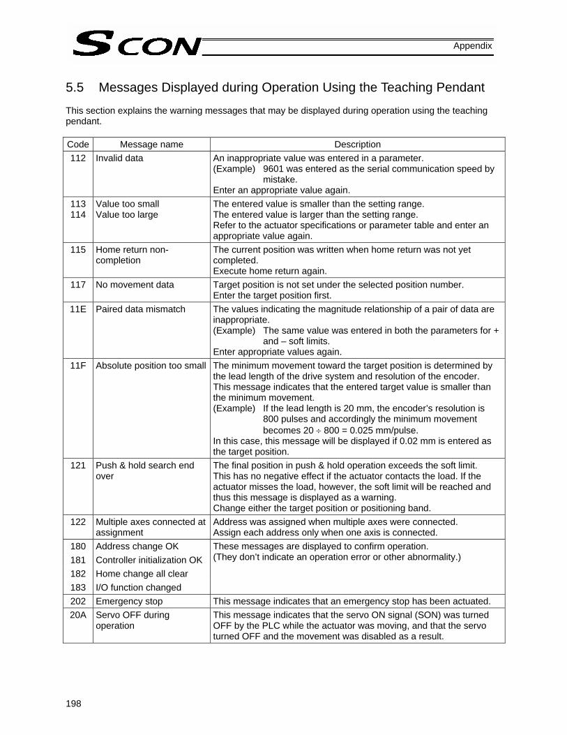
198
Appendix
5.5 Messages Displayed during Operation Using the Teaching Pendant This section explains the warning messages that may be displayed during operation using the teaching pendant. Code Message name Description 112 Invalid data An inappropriate value was entered in a parameter.
(Example) 9601 was entered as the serial communication speed by mistake.
Enter an appropriate value again. 113 114
Value too small Value too large
The entered value is smaller than the setting range. The entered value is larger than the setting range. Refer to the actuator specifications or parameter table and enter an appropriate value again.
115 Home return non-completion
The current position was written when home return was not yet completed. Execute home return again.
117 No movement data Target position is not set under the selected position number. Enter the target position first.
11E Paired data mismatch The values indicating the magnitude relationship of a pair of data are inappropriate. (Example) The same value was entered in both the parameters for +
and – soft limits. Enter appropriate values again.
11F Absolute position too small The minimum movement toward the target position is determined by the lead length of the drive system and resolution of the encoder. This message indicates that the entered target value is smaller than the minimum movement. (Example) If the lead length is 20 mm, the encoder’s resolution is
800 pulses and accordingly the minimum movement becomes 20 ÷ 800 = 0.025 mm/pulse.
In this case, this message will be displayed if 0.02 mm is entered as the target position.
121 Push & hold search end over
The final position in push & hold operation exceeds the soft limit. This has no negative effect if the actuator contacts the load. If the actuator misses the load, however, the soft limit will be reached and thus this message is displayed as a warning. Change either the target position or positioning band.
122 Multiple axes connected at assignment
Address was assigned when multiple axes were connected. Assign each address only when one axis is connected.
180 Address change OK 181 Controller initialization OK 182 Home change all clear 183 I/O function changed
These messages are displayed to confirm operation. (They don’t indicate an operation error or other abnormality.)
202 Emergency stop This message indicates that an emergency stop has been actuated. 20A Servo OFF during
operation This message indicates that the servo ON signal (SON) was turned OFF by the PLC while the actuator was moving, and that the servo turned OFF and the movement was disabled as a result.

199
Appendix
Code Message name Description 20C CSTR-ON during operation This message indicates that a movement command signal was turned
ON by the PLC while the actuator was moving, and that duplicate movement commands occurred as a result.
20E Soft limit over This message indicates that a soft limit was reached. 221 Write prohibited in monitor
mode This message indicates that an attempt was made to write data to the position table or any parameter in the monitor mode.
223 Operation prohibited in monitor mode
This message indicates that an attempt was made to move the actuator in the monitor mode.
301 Overrun error (M) 302 Framing error (M) 304 SCIR-QUE OV (M) 305 SCIS-QUE OV (M) 306 R-BF OV 308 Response timeout (M) 30A Packet R-QUE OV 30B Packet S-QUE OV
These messages indicate an error in the serial communication with the controller. Cause: [1] Garbage data due to the effect of noise
[2] Duplicate slave numbers when multiple controllers are controlled by serial communication
Action: [1] Adjust the wiring in a manner eliminating the effect of noise and review the installation of equipment, etc.
[2] Change the slave numbers to avoid duplication. If the message is still displayed after taking the above actions, please contact IAI.
307 Memory command refused This message indicates that the command was refused in the serial communication with the controller.
309 Write address error This message indicates that an indeterminate WRITE address error occurred in the serial communication with the controller. These conditions do not occur in normal operation. Should they occur, record the entire error list before cutting off the power for use in the cause investigation. Also contact IAI.
30C No connected axis This message indicates that no controller address is recognized. Cause: [1] The controller is not operating properly.
[2] Only the supplied communication cable (SGA/SGB) is disconnected.
[3] If a SIO converter is used, 24V is supplied to the converter but the link cable is not connected.
[4] The ADRS switch settings are duplicated by mistake when multiple controllers are linked.
Action: [1] Check if the RDY lamp on the controller is lit. If the lamp is not lit, the controller is faulty.
[2] If a spare teaching pendant is available, replace the current pendant with the spare unit, or with a PC, and see if the message disappears.
[3] Supply power after connecting the link cable between the converter and controller.
[4] Make sure the ADRS switch settings are not duplicated. If the message is still displayed after taking the above actions, please contact IAI.
200
Appendix
5.6 Specific Problems
I/O signals cannot be exchanged with the PLC. Cause: [1] The 24-V I/O power supply is connected in reverse.
(In this case, the input circuits are not affected, but the output circuits will be damaged.) [2] If the problem is with an output circuit, a circuit component may have been damaged due
to a large load that caused the current flowing into the circuit to exceed the maximum current.
[3] Contact failure in the connector or relay terminal block on the PLC end. [4] Contact failure between the female pins in the flat cable connector and the male pins on
the controller due to expanded female pins. Action: Check the connection condition of the power supply and connector, as well as the load on the
output side. If the cause is identified as [1] or [2], the controller must be replaced. If there is a possibility of [4], the flat cable must be replaced. Please contact IAI.
Warning: When performing a continuity check of the flat cable, pay due attention not to expand the female pins in the connector. It may cause contact failure and disable normal operation of the controller.
The ALM lamp illuminates when the power is input. (An alarm is present or the motor power is cut off.) * If the ALM output signal is OFF, an alarm is present. Connect a PC or teaching pendant to check
the nature of the error and then remove the cause. [1] Is the emergency-stop switch on the operation panel pressed or any necessary interlock
released? [2] Is parameter No. 42 (Enable function) enabled by mistake by connecting a teaching pendant not
supporting the enable switch? [3] If multiple controllers are connected, is the crossover wiring correct?
The SV lamp does not illuminate when the servo ON signal is input after the power was input.
(The servo does not turn ON.) Cause: [1] Contact failure of the flat cable
[2] Faulty controller Check the servo ON signal (SON) on the I/O monitor screen of the PC or teaching pendant. If the signal is input, probably the controller is faulty. Please contact IAI.

201
Appendix
Home return ends in the middle in a vertical application.
Cause: [1] The load exceeds the rating. [2] The ball screw is receiving torsional stress due to the affixing method of the actuator,
tightening of bolts only on one side, etc. [3] The slide resistance of the actuator itself is large.
Action: [1] Increase the value set in parameter No. 13 (Current-limiting value during home return). Increasing this value will cause the home return torque to increase, so do not increase the parameter setting above 75%.
[2] Loosen the fixing bolts and check if the slider moves smoothly. If the slider moves smoothly, review the affixing method and bolt tightening condition.
[3] If the slide resistance of the actuator itself is large, please contact IAI.
The actuator overshoots when decelerated to a stop. Cause: The load inertia is high due to an inappropriate balance of load and deceleration. Action: Decrease the acceleration/deceleration setting.
The home and target positions sometimes shift.
Cause: [1] The encoder waveform is disturbed by the effect of noise. [2] In the case of a rod-type actuator, the non-rotation accuracy increased due to application
of rotating moment to the rod. Action: [1] Check if the grounding is implemented correctly. Also check for any equipment being a
potential noise source. [2] The actuator may have to be replaced in some cases. Please contact IAI.
The actuator moves only a half of, or twice as much as, the specified movement.
Cause: [1] The combination of controller and actuator is wrong. The lead length of the ball screw varies depending on the actuator type, so a wrong combination will cause the movement and speed to change.
[2] Factory setting error at IAI Action: [1] If multiple actuators of different types must be used, confirm using the identification labels,
etc., that the correct actuator is connected to the controller. [2] Please contact IAI.
The SV lamp blinks.
The automatic servo-off mode is active. (This is not an error or fault.)

202
Appendix
Recording of Parameters
Recorded date: No. Category Name Unit Recorded data 1 a Zone boundary 1+ mm 2 a Zone boundary 1– mm 3 a Soft limit+ mm 4 a Soft limit– mm
5 a Home return direction [0: Reverse / 1: Forward] -
6 b Push & hold stop judgment period msec 7 d Servo gain number - 8 b Default speed mm/sec 9 b Default acceleration/deceleration G
10 b Default positioning band (in-position) mm 13 b Current-limiting value during home return % 14 b Dynamic brake [0: Disable / 1: Enable] -
15 c Pause input disable selection [0: Enable / 1: Disable] -
16 c SIO communication speed bps
17 c Minimum delay time for slave transmitter activation msec
18 b Home-sensor input polarity - 19 b Overrun-sensor input polarity - 20 b Creep-sensor input polarity -
21 c Servo ON input disable selection [0: Enable / 1: Disable] -
22 a Home return offset mm 23 a Zone boundary 2+ mm 24 a Zone boundary 2– mm 25 c PIO pattern selection - 26 b PIO jog speed mm/sec
27 c Movement command type [0: Level / 1: Edge] -
31 d Speed loop proportional gain - 32 d Speed loop integral gain - 33 d Torque filter time constant - 34 b Push speed mm/sec 35 b Safety speed mm/sec 36 b Automatic servo-off delay time 1 sec 37 b Automatic servo-off delay time 2 sec 38 b Automatic servo-off delay time 3 sec
39 c Output mode of position complete signal [0: PEND / 1: INP] -
40 c Home-return input disable selection [0: Enable / 1: Disable] -
41 c Operating-mode input disable selection [0: Enable / 1: Disable] -
42 b Enable function [0: Enable / 1: Disable] - 45 c Silent interval multiplier time 46 b Speed override % 47 b PIO jog speed 2 mm/sec 48 b PIO inching distance mm 49 b PIO inching distance 2 mm 50 b Load output judgment time msec 52 b Default acceleration/deceleration mode - 53 b Default standstill mode -

203
Appendix
No. Category Name Unit Recorded data 54 d Current-control band number -
55 b Position-command primary filter time constant msec
56 b S-motion ratio setting %
72 e Timer period for emergency-stop relay fusing monitor msec
73 e Encoder voltage level - 74 e PIO power monitor [0: Enable / 1: Disable] -
75 e Electromagnetic-brake power monitor [0: Disable / 1: Enable] -

204

Catalog No.: MJ0161-3A-Dec1906-1
Head Office: 2690 W. 237th Street, Torrance, CA 90505 TEL (310) 891-6015 FAX (310) 891-0815
Chicago Office: 1261 Hamilton Parkway, Itasca, IL 60143 TEL (630) 467-9900 FAX (630) 467-9912
New Jersey Office: 7 South Main St., Suite-F, Marlboro, NJ 07746 TEL (732) 683-9101 FAX (732) 683-9103
Website: www.intelligentactuator.com
Ober der Röth 4, D-65824 Schwalbach am Taunus, Germany TEL 06196-88950 FAX 06196-889524
The information contained in this document is subject to change without notice for the purpose of product improvement. Copyright © 2006. Nov. IAI Corporation. All rights reserved.


![ROBO CYLINDER Series PCON, ACON, SCON, ERC2 Communication... · Operation Manual, Second Edition ROBO CYLINDER Series PCON, ACON, SCON, ERC2 Serial Communication [Modbus Version]](https://static.fdocuments.us/doc/165x107/5a9d9c787f8b9a42488b7b3e/robo-cylinder-series-pcon-acon-scon-communicationoperation-manual-second.jpg)