06/04/2014 Update on 52 Weldability. - nrc.gov · • Example of hot cracks in 152 weld metal at...
30
Steve McCracken and Jon Tatman EPRI Welding & Repair Technology Center Update on 52 Weldability Influence of High Si-S Stainless Steels on the Solidification Cracking Susceptibility of High Chromium Nickel-Base Metals Industry/U.S. NRC Materials Program Technical Information Exchange Meeting Rockville, MD Wednesday June 4, 2014
Transcript of 06/04/2014 Update on 52 Weldability. - nrc.gov · • Example of hot cracks in 152 weld metal at...
Steve McCracken and Jon Tatman EPRI Welding & Repair Technology Center
Update on 52 Weldability
Influence of High Si-S Stainless Steels on the Solidification Cracking Susceptibility of High Chromium Nickel-Base Metals
Industry/U.S. NRC Materials Program Technical
Information Exchange Meeting
Rockville, MD Wednesday June 4, 2014

2 © 2014 Electric Power Research Institute, Inc. All rights reserved. Welding and Repair Technology Center
WRTC Roadmap: Alloy 52 Weldability Solution
52 Weldability Testing New High Cr Ni-Base Alloy ASME Code & NRC Support Magnetic Stir Welding 52M on CASS Studies Low Dilution LBW Underwater LBW Friction Stir Welding Effective Heat Input Equation Effective Dilution Equation Inlay/Onlay Repair Excavate & Weld Repair New Simplified DDC Test

3 © 2014 Electric Power Research Institute, Inc. All rights reserved. Welding and Repair Technology Center
EPRI Report 1025167
• Measures to Minimize 52M Hot Cracking on Stainless Steel Base Materials
• Publication Date: December 2012 – Background on hot cracking
experience – Focus on 52M – Hot cracking testing approach
and test results – Discussion with measures to
minimize hot cracking – Dilution control & buffer layer
options – Future work
4 © 2014 Electric Power Research Institute, Inc. All rights reserved. Welding and Repair Technology Center
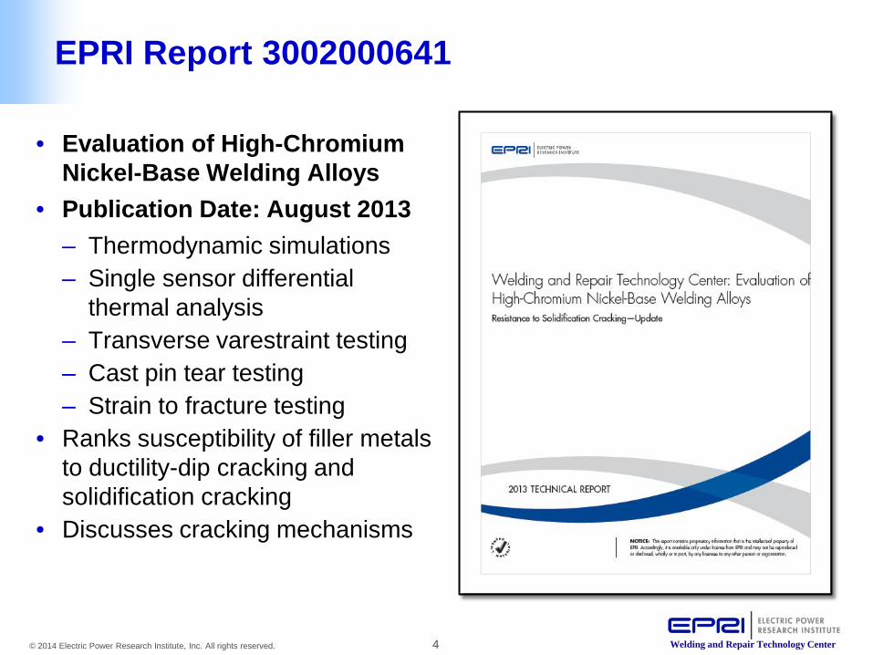
• Evaluation of High-Chromium Nickel-Base Welding Alloys
• Publication Date: August 2013 – Thermodynamic simulations – Single sensor differential
thermal analysis – Transverse varestraint testing – Cast pin tear testing – Strain to fracture testing
• Ranks susceptibility of filler metals to ductility-dip cracking and solidification cracking
• Discusses cracking mechanisms
EPRI Report 3002000641
5 © 2014 Electric Power Research Institute, Inc. All rights reserved. Welding and Repair Technology Center
52M Hot Cracking on Stainless Steel Presentation Outline
• Background and Motivation
• Test Design and Approach
• Test Results and Observations - Hot Crack Ranking of Filler Metals Tested - Influence of Si and S on Hot Cracking - Influence of Si and S on Dilution and Bead Shape - Safe Dilution Threshold - Safe Si and S+P Limits
• Conclusions and Guidelines
6 © 2014 Electric Power Research Institute, Inc. All rights reserved. Welding and Repair Technology Center
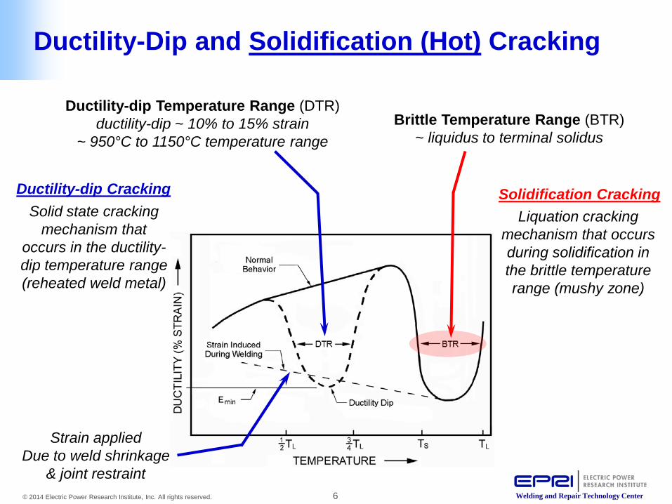
Ductility-Dip and Solidification (Hot) Cracking
Ductility-dip Temperature Range (DTR) ductility-dip ~ 10% to 15% strain
~ 950°C to 1150°C temperature range Brittle Temperature Range (BTR)
~ liquidus to terminal solidus
Strain applied Due to weld shrinkage
& joint restraint
Liquation cracking mechanism that occurs during solidification in the brittle temperature range (mushy zone)
Solidification Cracking Solid state cracking
mechanism that occurs in the ductility-dip temperature range (reheated weld metal)
Ductility-dip Cracking
7 © 2014 Electric Power Research Institute, Inc. All rights reserved. Welding and Repair Technology Center
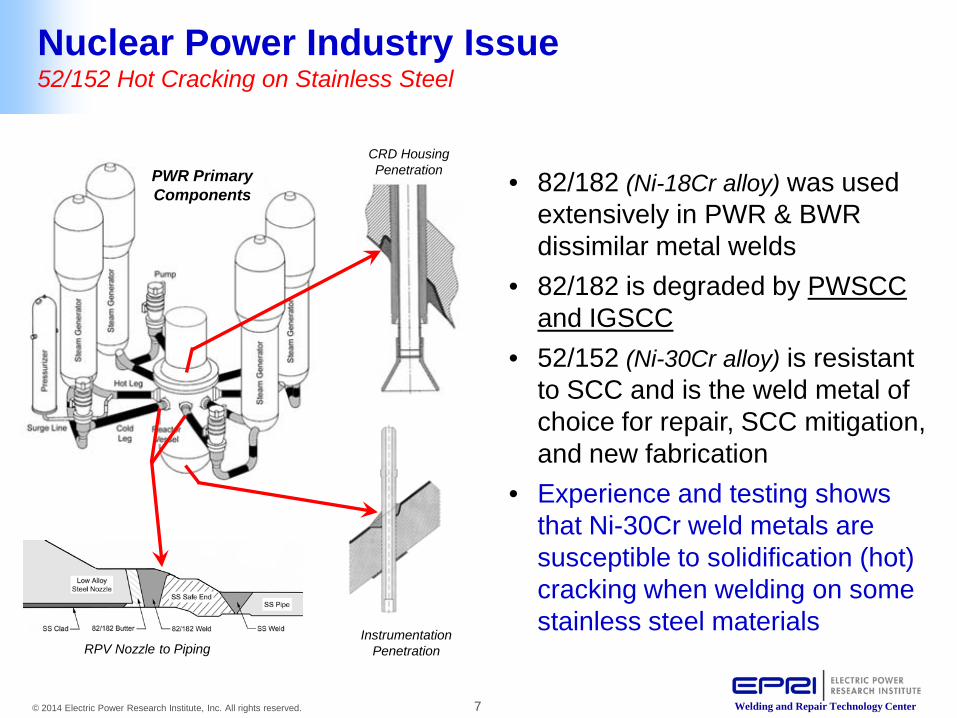
Nuclear Power Industry Issue 52/152 Hot Cracking on Stainless Steel
• 82/182 (Ni-18Cr alloy) was used extensively in PWR & BWR dissimilar metal welds
• 82/182 is degraded by PWSCC and IGSCC
• 52/152 (Ni-30Cr alloy) is resistant to SCC and is the weld metal of choice for repair, SCC mitigation, and new fabrication
• Experience and testing shows that Ni-30Cr weld metals are susceptible to solidification (hot) cracking when welding on some stainless steel materials
PWR Primary Components
CRD Housing Penetration
Instrumentation Penetration RPV Nozzle to Piping
8 © 2014 Electric Power Research Institute, Inc. All rights reserved. Welding and Repair Technology Center
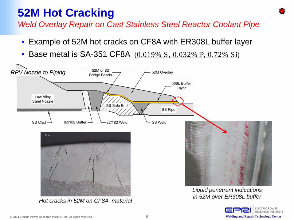
52M Hot Cracking Weld Overlay Repair on Cast Stainless Steel Reactor Coolant Pipe
• Example of 52M hot cracks on CF8A with ER308L buffer layer • Base metal is SA-351 CF8A (0.019% S, 0.032% P, 0.72% Si)
Liquid penetrant indications in 52M over ER308L buffer
Hot cracks in 52M on CF8A material
RPV Nozzle to Piping

9 © 2014 Electric Power Research Institute, Inc. All rights reserved. Welding and Repair Technology Center
152 Hot Cracking Buttering in J-groove Pocket on Reactor Vessel Head
• Example of hot cracks in 152 weld metal at interface between J-groove weld butter and SAW strip clad deposit
• SAW clad deposit is EQ308L (0.012% S, 0.014% P, 0.96% Si)
SA-508 Gr3 Cl1
EQ308L/309L SAW Strip Clad
Alloy 152 Butter
Liquid penetrant indications at 152 / EQ308L interface
Replication of hot crack
CRD Housing 152 Butter

10 © 2014 Electric Power Research Institute, Inc. All rights reserved. Welding and Repair Technology Center
• Background and Motivation
• Test Design and Approach
• Test Results and Observations - Hot Crack Ranking of Filler Metals Tested - Influence of Si and S on Hot Cracking - Influence of Si and S on Dilution and Bead Shape - Safe Dilution Threshold - Safe Si and S+P Limits
• Conclusions and Recommendations
52M Hot Cracking on Stainless Steel Presentation Outline
11 © 2014 Electric Power Research Institute, Inc. All rights reserved. Welding and Repair Technology Center
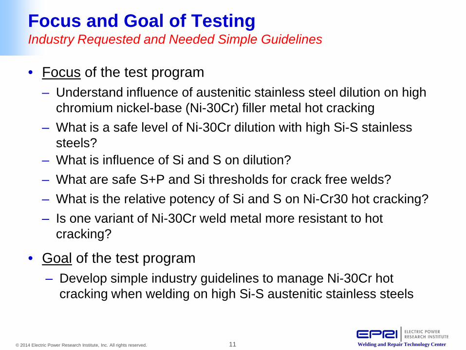
Focus and Goal of Testing Industry Requested and Needed Simple Guidelines
• Focus of the test program – Understand influence of austenitic stainless steel dilution on high
chromium nickel-base (Ni-30Cr) filler metal hot cracking – What is a safe level of Ni-30Cr dilution with high Si-S stainless
steels? – What is influence of Si and S on dilution? – What are safe S+P and Si thresholds for crack free welds? – What is the relative potency of Si and S on Ni-Cr30 hot cracking? – Is one variant of Ni-30Cr weld metal more resistant to hot
cracking?
• Goal of the test program – Develop simple industry guidelines to manage Ni-30Cr hot
cracking when welding on high Si-S austenitic stainless steels
12 © 2014 Electric Power Research Institute, Inc. All rights reserved. Welding and Repair Technology Center
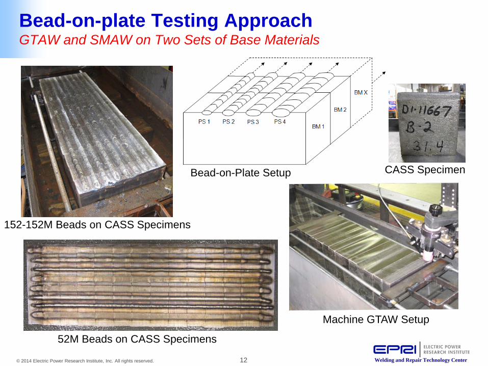
Machine GTAW Setup
52M Beads on CASS Specimens
CASS Specimen Bead-on-Plate Setup
152-152M Beads on CASS Specimens
Bead-on-plate Testing Approach GTAW and SMAW on Two Sets of Base Materials
13 © 2014 Electric Power Research Institute, Inc. All rights reserved. Welding and Repair Technology Center
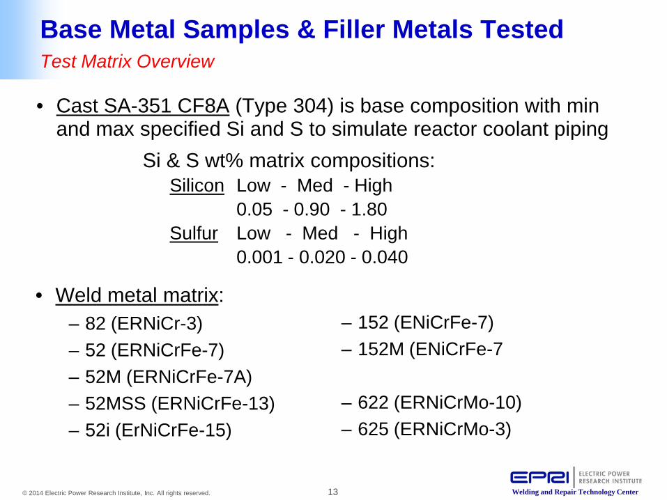
Base Metal Samples & Filler Metals Tested Test Matrix Overview
• Cast SA-351 CF8A (Type 304) is base composition with min and max specified Si and S to simulate reactor coolant piping
Si & S wt% matrix compositions: Silicon Low - Med - High 0.05 - 0.90 - 1.80 Sulfur Low - Med - High 0.001 - 0.020 - 0.040
• Weld metal matrix: – 82 (ERNiCr-3) – 52 (ERNiCrFe-7) – 52M (ERNiCrFe-7A) – 52MSS (ERNiCrFe-13) – 52i (ErNiCrFe-15)
– 152 (ENiCrFe-7) – 152M (ENiCrFe-7
– 622 (ERNiCrMo-10) – 625 (ERNiCrMo-3)
14 © 2014 Electric Power Research Institute, Inc. All rights reserved. Welding and Repair Technology Center
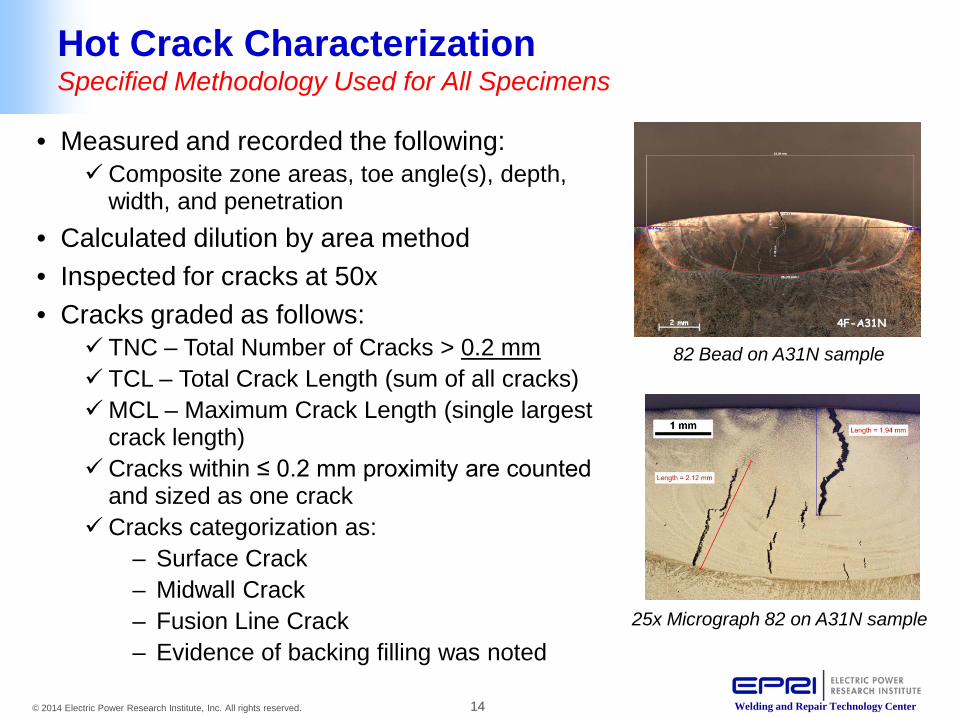
Hot Crack Characterization Specified Methodology Used for All Specimens
82 Bead on A31N sample
25x Micrograph 82 on A31N sample
• Measured and recorded the following: Composite zone areas, toe angle(s), depth,
width, and penetration • Calculated dilution by area method • Inspected for cracks at 50x • Cracks graded as follows:
TNC – Total Number of Cracks > 0.2 mm TCL – Total Crack Length (sum of all cracks) MCL – Maximum Crack Length (single largest
crack length) Cracks within ≤ 0.2 mm proximity are counted
and sized as one crack Cracks categorization as:
– Surface Crack – Midwall Crack – Fusion Line Crack – Evidence of backing filling was noted

15 © 2014 Electric Power Research Institute, Inc. All rights reserved. Welding and Repair Technology Center
• Background and Motivation
• Testing Design and Approach
• Test Results and Observations - Hot Crack Ranking of Filler Metals Tested - Influence of Si and S on Hot Cracking - Influence of Si and S on Dilution and Bead Shape - Safe Dilution Threshold - Safe Si and S+P Limits
• Conclusions and Recommendations
52M Hot Cracking on Stainless Steel Presentation Outline

16 © 2014 Electric Power Research Institute, Inc. All rights reserved. Welding and Repair Technology Center
Hot Crack Response Comparison by Filler Metal Phase 2 CF8A CASS-b Set (169.0 KW/in2)

17 © 2014 Electric Power Research Institute, Inc. All rights reserved. Welding and Repair Technology Center
Hot Crack Response Comparison by Filler Metal Phase 2 CF8A CASS-b Set (213.6 KW/in2)
All Cracks Healed by Backfilling in 625
Limited Backfilling Observed at Crack
Tips in 52MSS

18 © 2014 Electric Power Research Institute, Inc. All rights reserved. Welding and Repair Technology Center
Crack Susceptibility Plot with Sulfur (S) GTAW – 52M-B on CASS-b material set
CF8A CASS Samples
19 © 2014 Electric Power Research Institute, Inc. All rights reserved. Welding and Repair Technology Center
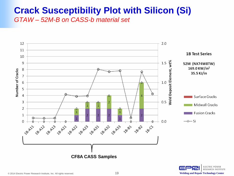
CF8A CASS Samples
Crack Susceptibility Plot with Silicon (Si) GTAW – 52M-B on CASS-b material set
20 © 2014 Electric Power Research Institute, Inc. All rights reserved. Welding and Repair Technology Center
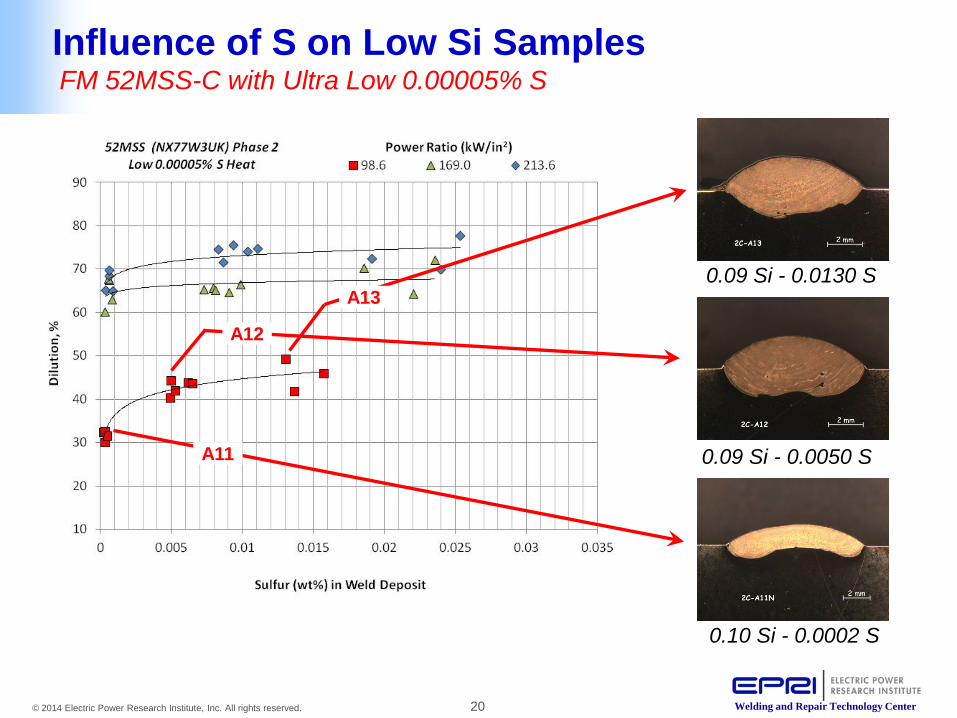
No. Dil Si S A11N 32.5 0.101097 0.000199 A12 44.4 0.093869 0.004961 A13 49.3 0.093437 0.013039
Influence of S on Low Si Samples FM 52MSS-C with Ultra Low 0.00005% S
A13
A12
A11
0.09 Si - 0.0130 S
0.09 Si - 0.0050 S
0.10 Si - 0.0002 S
21 © 2014 Electric Power Research Institute, Inc. All rights reserved. Welding and Repair Technology Center
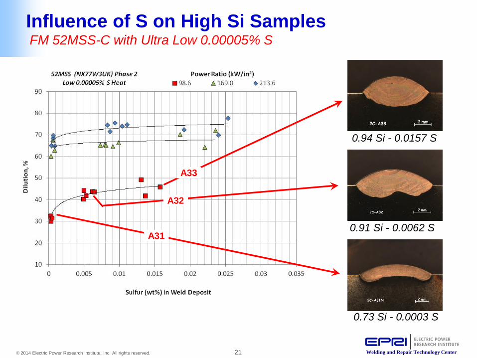
Sample Dil Si S 2C-A33 45.9 0.941227 0.015733 2C-A32 43.8 0.9166 0.006165
2C-A31N 32.5 0.730888 0.00031
0.94 Si - 0.0157 S
0.91 Si - 0.0062 S
0.73 Si - 0.0003 S
Influence of S on High Si Samples FM 52MSS-C with Ultra Low 0.00005% S
A33
A32
A31

22 © 2014 Electric Power Research Institute, Inc. All rights reserved. Welding and Repair Technology Center
Influence of Si and S on Bead Shape 52MSS-C (0.00005% S Wire with Power Ratio 98.6 kW/in2)
Increasing Si
Incr
easi
ng S
23 © 2014 Electric Power Research Institute, Inc. All rights reserved. Welding and Repair Technology Center
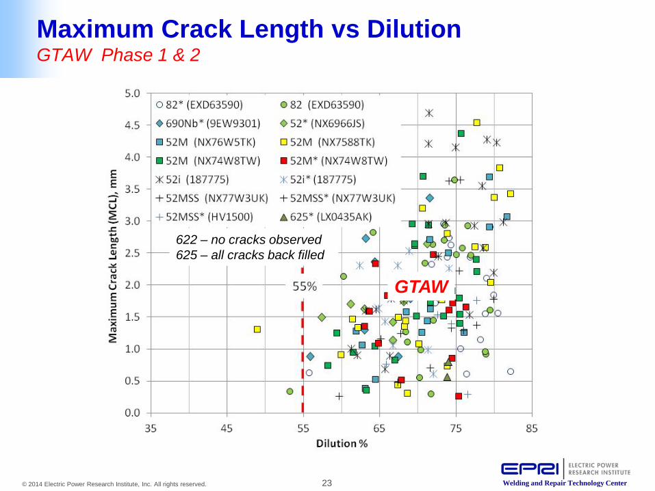
Maximum Crack Length vs Dilution GTAW Phase 1 & 2
52M-d Si S Dil 2d-2Si 0.520209 0.021149 48.93
82-f Si S Dil 2f-67 1.101413 0.002064 53.19
GTAW
622 – no cracks observed 625 – all cracks back filled

24 © 2014 Electric Power Research Institute, Inc. All rights reserved. Welding and Repair Technology Center
Maximum Crack Length vs Dilution GTAW Phase 1 & SMAW Phase 3
SMAW GTAW
25 © 2014 Electric Power Research Institute, Inc. All rights reserved. Welding and Repair Technology Center
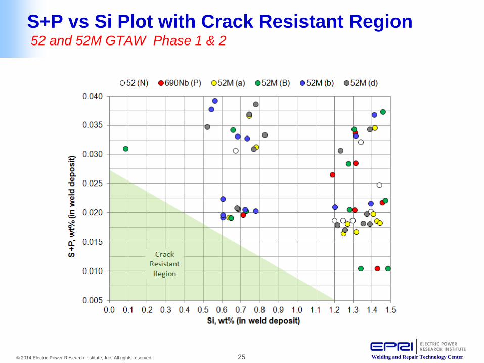
S+P vs Si Plot with Crack Resistant Region 52 and 52M GTAW Phase 1 & 2
26 © 2014 Electric Power Research Institute, Inc. All rights reserved. Welding and Repair Technology Center
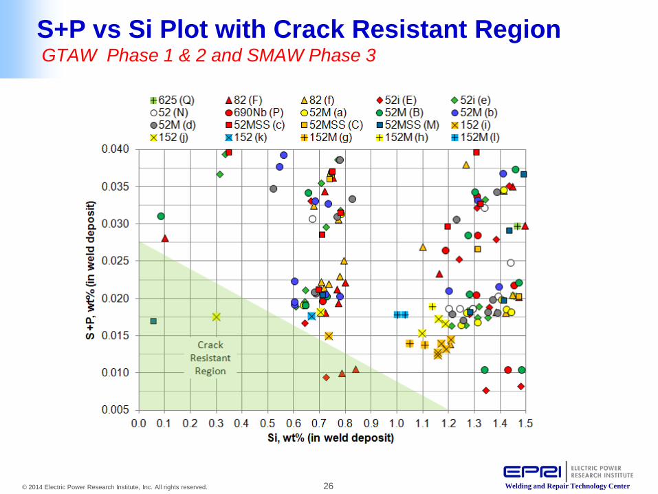
S+P vs Si Plot with Crack Resistant Region GTAW Phase 1 & 2 and SMAW Phase 3

27 © 2014 Electric Power Research Institute, Inc. All rights reserved. Welding and Repair Technology Center
• Background and Motivation
• Test Design and Approach
• Test Results and Observations - Hot Crack Ranking of Filler Metals Tested - Influence of Si and S on Hot Cracking - Influence of Si and S on Dilution and Bead Shape - Safe Dilution Threshold - Safe Si and S+P Limits
• Conclusions and Recommendations
52M Hot Cracking on Stainless Steel Presentation Outline

28 © 2014 Electric Power Research Institute, Inc. All rights reserved. Welding and Repair Technology Center
Conclusions Hot Cracking From Dilution with Stainless Steel
• Ranking of filler metals tested from most to least resistant 622 (crack free) < 625 (back filled) < 52MSS < 52 < 52M <52i
• High silicon in austenitic stainless steel promotes hot cracking in high Cr Nickel-base filler metals
• High sulfur did not strongly promote hot cracking • Dilution can vary as much as 25% between 0.00005% and
0.034% S base materials • Dilution control (≤ 55% for GTAW and ≤ 35% for SMAW) is
an effective tool to prevent hot cracking of Ni-30Cr weld metals when welding on high Si-S stainless steel
29 © 2014 Electric Power Research Institute, Inc. All rights reserved. Welding and Repair Technology Center
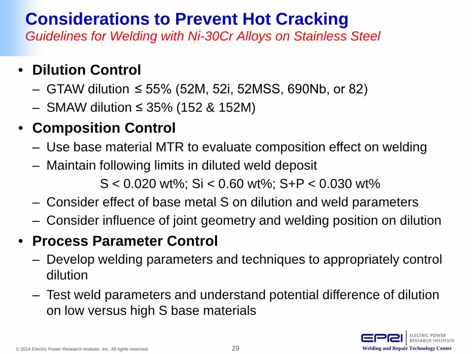
• Dilution Control – GTAW dilution ≤ 55% (52M, 52i, 52MSS, 690Nb, or 82) – SMAW dilution ≤ 35% (152 & 152M)
• Composition Control – Use base material MTR to evaluate composition effect on welding – Maintain following limits in diluted weld deposit
S < 0.020 wt%; Si < 0.60 wt%; S+P < 0.030 wt% – Consider effect of base metal S on dilution and weld parameters – Consider influence of joint geometry and welding position on dilution
• Process Parameter Control – Develop welding parameters and techniques to appropriately control
dilution – Test weld parameters and understand potential difference of dilution
on low versus high S base materials
Considerations to Prevent Hot Cracking Guidelines for Welding with Ni-30Cr Alloys on Stainless Steel
30 © 2014 Electric Power Research Institute, Inc. All rights reserved. Welding and Repair Technology Center
Together…Shaping the Future of Electricity
EPRI Contacts: Steve McCracken – [email protected] 704-595-2627
Jon Tatman – [email protected] 704-595-2762