05 Ra41235en06gla1 Ue States and Ltesae Signaling
83
RA41235EN06GLA1 UE States and LTE/SAE Signaling 1
-
Upload
gio-zakradze -
Category
Documents
-
view
10 -
download
2
description
05 Ra41235en06gla1 Ue States and Ltesae Signaling
Transcript of 05 Ra41235en06gla1 Ue States and Ltesae Signaling

RA41235EN06GLA1
UE States and LTE/SAE Signaling
1
RA41235EN06GLA1
UE States and LTE/SAE Signaling
2
RA41235EN06GLA1
UE States and LTE/SAE Signaling
4

RA41235EN06GLA1
UE States and LTE/SAE Signaling
5
RA41235EN06GLA1
UE States and LTE/SAE Signaling
6
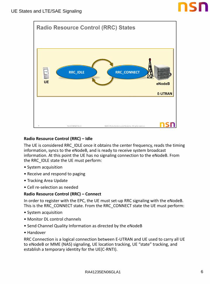
Radio Resource Control (RRC) – Idle
The UE is considered RRC_IDLE once it obtains the center frequency, reads the timing information, syncs to the eNodeB, and is ready to receive system broadcast information. At this point the UE has no signaling connection to the eNodeB. From the RRC_IDLE state the UE must perform:
• System acquisition
• Receive and respond to paging
• Tracking Area Update
• Cell re-selection as needed
Radio Resource Control (RRC) – Connect
In order to register with the EPC, the UE must set-up RRC signaling with the eNodeB. This is the RRC_CONNECT state. From the RRC_CONNECT state the UE must perform:
• System acquisition
• Monitor DL control channels
• Send Channel Quality Information as directed by the eNodeB
• Handover
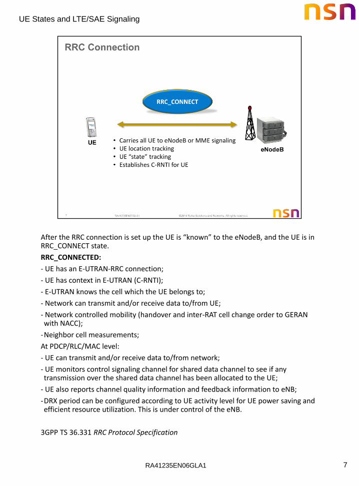
RRC Connection is a logical connection between E-UTRAN and UE used to carry all UE to eNodeB or MME (NAS) signaling, UE location tracking, UE “state” tracking, and establish a temporary identity for the UE(C-RNTI).
RA41235EN06GLA1
UE States and LTE/SAE Signaling
7
After the RRC connection is set up the UE is “known” to the eNodeB, and the UE is in RRC_CONNECT state.
RRC_CONNECTED:
- UE has an E-UTRAN-RRC connection;
- UE has context in E-UTRAN (C-RNTI);
- E-UTRAN knows the cell which the UE belongs to;
- Network can transmit and/or receive data to/from UE;
- Network controlled mobility (handover and inter-RAT cell change order to GERAN with NACC);
-Neighbor cell measurements;
At PDCP/RLC/MAC level:
- UE can transmit and/or receive data to/from network;
- UE monitors control signaling channel for shared data channel to see if any transmission over the shared data channel has been allocated to the UE;
- UE also reports channel quality information and feedback information to eNB;
-DRX period can be configured according to UE activity level for UE power saving and efficient resource utilization. This is under control of the eNB.
3GPP TS 36.331 RRC Protocol Specification
RA41235EN06GLA1
UE States and LTE/SAE Signaling
8
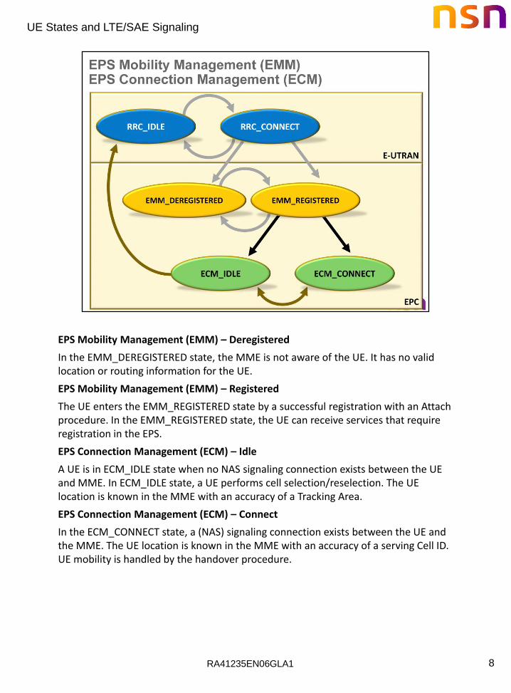
EPS Mobility Management (EMM) – Deregistered
In the EMM_DEREGISTERED state, the MME is not aware of the UE. It has no valid location or routing information for the UE.
EPS Mobility Management (EMM) – Registered
The UE enters the EMM_REGISTERED state by a successful registration with an Attach procedure. In the EMM_REGISTERED state, the UE can receive services that require registration in the EPS.
EPS Connection Management (ECM) – Idle
A UE is in ECM_IDLE state when no NAS signaling connection exists between the UE and MME. In ECM_IDLE state, a UE performs cell selection/reselection. The UE location is known in the MME with an accuracy of a Tracking Area.
EPS Connection Management (ECM) – Connect
In the ECM_CONNECT state, a (NAS) signaling connection exists between the UE and the MME. The UE location is known in the MME with an accuracy of a serving Cell ID. UE mobility is handled by the handover procedure.
RA41235EN06GLA1
UE States and LTE/SAE Signaling
9
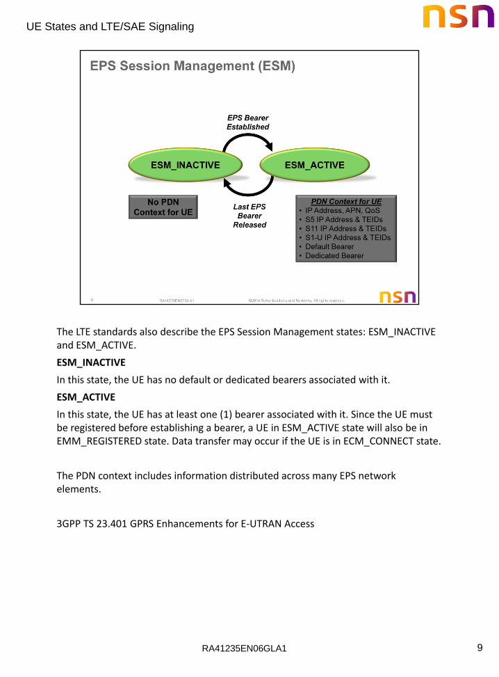
The LTE standards also describe the EPS Session Management states: ESM_INACTIVE and ESM_ACTIVE.
ESM_INACTIVE
In this state, the UE has no default or dedicated bearers associated with it.
ESM_ACTIVE
In this state, the UE has at least one (1) bearer associated with it. Since the UE must be registered before establishing a bearer, a UE in ESM_ACTIVE state will also be in EMM_REGISTERED state. Data transfer may occur if the UE is in ECM_CONNECT state.
The PDN context includes information distributed across many EPS network elements.
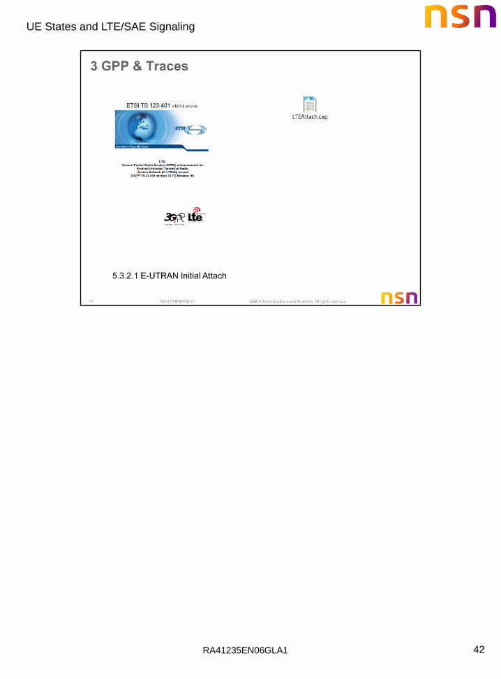
3GPP TS 23.401 GPRS Enhancements for E-UTRAN Access
RA41235EN06GLA1
UE States and LTE/SAE Signaling
10
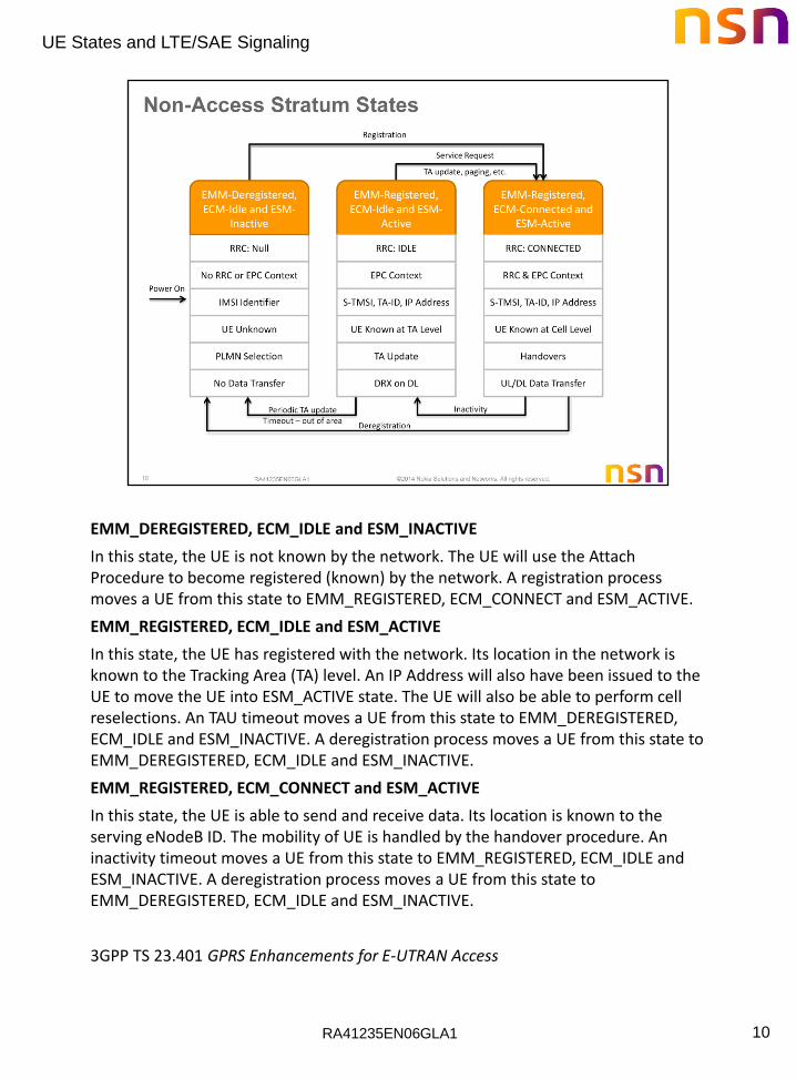
EMM_DEREGISTERED, ECM_IDLE and ESM_INACTIVE
In this state, the UE is not known by the network. The UE will use the Attach Procedure to become registered (known) by the network. A registration process moves a UE from this state to EMM_REGISTERED, ECM_CONNECT and ESM_ACTIVE.
EMM_REGISTERED, ECM_IDLE and ESM_ACTIVE
In this state, the UE has registered with the network. Its location in the network is known to the Tracking Area (TA) level. An IP Address will also have been issued to the UE to move the UE into ESM_ACTIVE state. The UE will also be able to perform cell reselections. An TAU timeout moves a UE from this state to EMM_DEREGISTERED, ECM_IDLE and ESM_INACTIVE. A deregistration process moves a UE from this state to EMM_DEREGISTERED, ECM_IDLE and ESM_INACTIVE.
EMM_REGISTERED, ECM_CONNECT and ESM_ACTIVE
In this state, the UE is able to send and receive data. Its location is known to the serving eNodeB ID. The mobility of UE is handled by the handover procedure. An inactivity timeout moves a UE from this state to EMM_REGISTERED, ECM_IDLE and ESM_INACTIVE. A deregistration process moves a UE from this state to EMM_DEREGISTERED, ECM_IDLE and ESM_INACTIVE.
3GPP TS 23.401 GPRS Enhancements for E-UTRAN Access
RA41235EN06GLA1
UE States and LTE/SAE Signaling
11
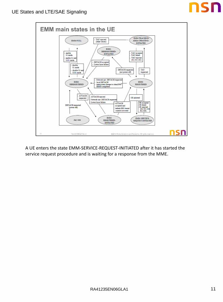
A UE enters the state EMM-SERVICE-REQUEST-INITIATED after it has started the service request procedure and is waiting for a response from the MME.
RA41235EN06GLA1
UE States and LTE/SAE Signaling
12

RA41235EN06GLA1
UE States and LTE/SAE Signaling
13
Selected Context Information in the HSS
General UE Context Information PDN Subscription Request
IMSI Context Identifier
MSISDN (Telephone Number) IP Address(es)
IMEI / IMEI-SV Access Point Name (APN)
Serving MME Address EPS Subscribed QoS profile
MME Capabilities Subscribed-APN-Bandwidth
Operator Determined Barring status EPS Bearer Context Charging Characteristics
Access Restriction Visited PLMN P-GW allowed?
EPS Subscribed Charging Characteristics P-GW Identity
Trace Information
Subscribed-UE-non GBR
Bandwidth
APN-Domain Name
3GPP TS 23.401 GPRS Enhancements for E-UTRAN Access

RA41235EN06GLA1
UE States and LTE/SAE Signaling
14
Selected Context Information in the UE
General UE Context PDN Subscription Context EPS Bearer within PDN
Information Connection
IMSI IP Address(es) EPS Bearer ID
IMEI / IMEI-SV Access Point Name (APN) Transaction ID
Mobility Management State Bandwidth for Non-GBR EPS Bearer QoS
Bearers
GUTI EPS Bearer ID for Default UL Traffic Flow Template
Bearer
Tracking Area List
Last Visited Tracking Area ID
UE – specific DRX
Parameters
Security Parameters
3GPP TS 23.401 GPRS Enhancements for E-UTRAN Access

RA41235EN06GLA1
UE States and LTE/SAE Signaling
15
Selected Context information in the MME
General UE Context Information Active PDN Connection
IMSI, IMEI/IMEI-SV UE IP Address(es)
Mobility Management State APN in use and subscribed
GUTI Bandwidth for Non-GBR Bearers
Tracking Area List Bearer info for Default Bearer
Last Reported Tracking Area ID P-GW info for S5/S8 (Control Plane)
Security Parameters EPS Bearer within PDN Connection
Selected Core Network ID EPS Bearer ID
MME/S-GW info for S11 (CP) Transaction ID
eNodeB/MME UE S1AP IDs EPS Bearer QoS
eNodeB Address in use S-GW info for S1-U (User Plane)
E-UTRAN Cell Global ID (ECGI) S-GW/P-GW info for S5/S8 (User Plane)
Charging Information Charging Information
RA41235EN06GLA1
UE States and LTE/SAE Signaling
16
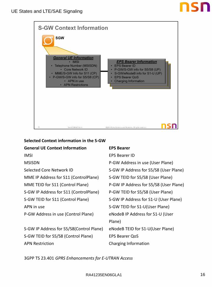
Selected Context information in the S-GW
General UE Context Information EPS Bearer
IMSI EPS Bearer ID
MSISDN P-GW Address in use (User Plane)
Selected Core Network ID S-GW IP Address for S5/S8 (User Plane)
MME IP Address for S11 (ControlPlane) S-GW TEID for S5/S8 (User Plane)
MME TEID for S11 (Control Plane) P-GW IP Address for S5/S8 (User Plane)
S-GW IP Address for S11 (ControlPlane) P-GW TEID for S5/S8 (User Plane)
S-GW TEID for S11 (Control Plane) S-GW IP Address for S1-U (User Plane)
APN in use S-GW TEID for S1-U(User Plane)
P-GW Address in use (Control Plane) eNodeB IP Address for S1-U (User
Plane)
S-GW IP Address for S5/S8(Control Plane) eNodeB TEID for S1-U(User Plane)
S-GW TEID for S5/S8 (Control Plane) EPS Bearer QoS
APN Restriction Charging Information
3GPP TS 23.401 GPRS Enhancements for E-UTRAN Access
RA41235EN06GLA1
UE States and LTE/SAE Signaling
17
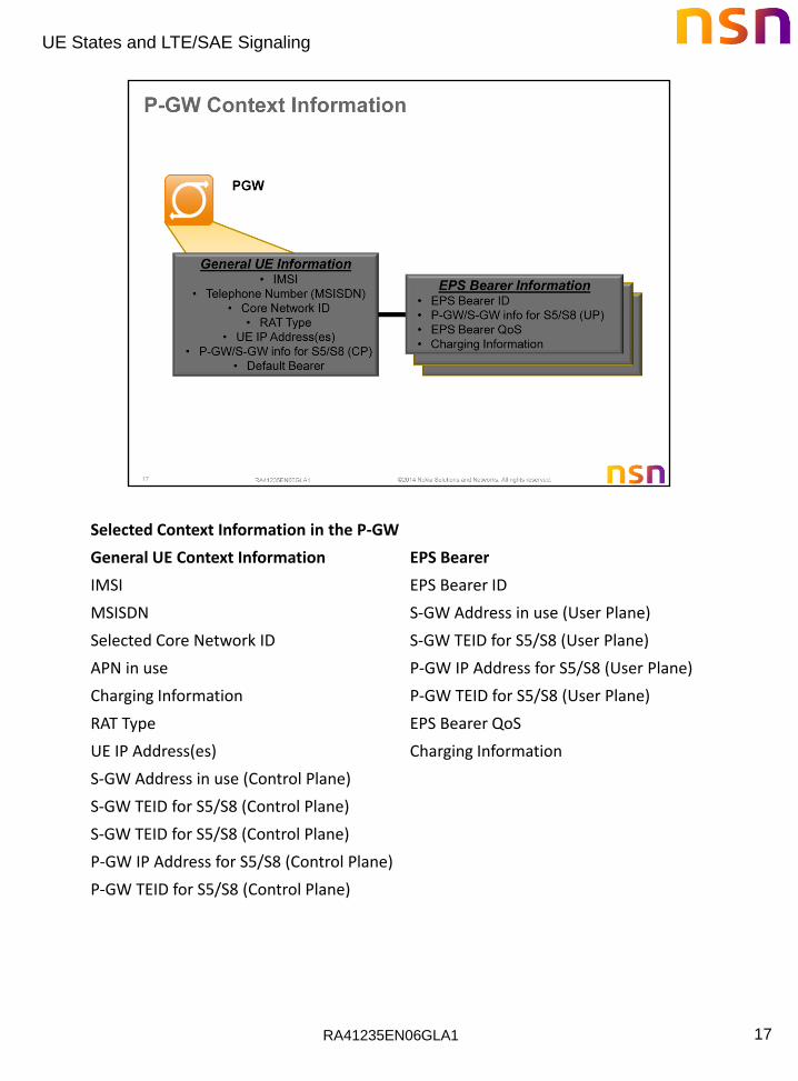
Selected Context Information in the P-GW
General UE Context Information EPS Bearer
IMSI EPS Bearer ID
MSISDN S-GW Address in use (User Plane)
Selected Core Network ID S-GW TEID for S5/S8 (User Plane)
APN in use P-GW IP Address for S5/S8 (User Plane)
Charging Information P-GW TEID for S5/S8 (User Plane)
RAT Type EPS Bearer QoS
UE IP Address(es) Charging Information
S-GW Address in use (Control Plane)
S-GW TEID for S5/S8 (Control Plane)
S-GW TEID for S5/S8 (Control Plane)
P-GW IP Address for S5/S8 (Control Plane)
P-GW TEID for S5/S8 (Control Plane)

RA41235EN06GLA1
UE States and LTE/SAE Signaling
18

RA41235EN06GLA1
UE States and LTE/SAE Signaling
19
Five (5) basic procedures:
• Attach
• Service Requests
• Tracking Area Update
• Handover
• Detach

RA41235EN06GLA1
UE States and LTE/SAE Signaling
20
In order to send and receive data, the UE has to attach to both the E-UTRAN and the EPC.
Attaching to the E-UTRAN synchronizes the UE to the eNodeB allowing the UE to receive system broadcast information to continue with the network attachment process.
Attaching to the EPC provides the UE with an IP address, sets-up QoS, and establishes bearer service.
Here is a simplified view of the Network Attach process we will be discussing in this lesson.
Attach – synchronizes UE to eNodeB and allows the UE to receive system broadcast information to continue with the network attachment process.
Authenticate – UE is authenticated on the system.
MME Registration – UE is “assigned” to and registered on an MME.
P-GW Select – a P-GW is assigned. An IP address for the UE is also assigned during this step.
MME / S-GW Accept – the MME and S-GW “accept” the QoS parameters, bearers, and other system information that was negotiated during the attach process and passes this information to the UE.
UE Ack Network Attach – UE acknowledges the MME / S-GW accept and attaches to the LTE Network.

RA41235EN06GLA1
UE States and LTE/SAE Signaling
21
When the UE powers-up, it looks for and acquires the RF center frequency. Once it obtains the center frequency, it reads the timing information and syncs to the eNodeB. With the UE synchronized to the eNodeB, it can receive system broadcast information. The UE is now considered in the RRC_IDLE state.

RA41235EN06GLA1
UE States and LTE/SAE Signaling
22
System information is broadcast in System Information (SI) Radio Resource Control (RRC) messages. The SI-M carries the Master Information Block (MIB). It is transmitted on the BCH/PBCH and contains:
• DL system bandwidth
• Number of transmit antennas
• System frame number
The SI-1 carries the System Information Block Type 1 (SIB Type 1). It is transmitted on the DL-SCH/PDSCH and contains:
• PLMN identity
• Tracking Area code
• Cell identity
• Cell barring status
• Other SIB scheduling and mapping information

RA41235EN06GLA1
UE States and LTE/SAE Signaling
23
3GPP TS 36.331 RRC Protocol Specification

RA41235EN06GLA1
UE States and LTE/SAE Signaling
24
3GPP TS 36.331 RRC Protocol Specification

RA41235EN06GLA1
UE States and LTE/SAE Signaling
25
Cell Service Types
Each cell supports one of the following service levels.
• Suitable Cell – a cell on which the UE may obtain normal service
• Acceptable Cell – a cell on which the UE may obtain limited service (originate emergency calls)
• Barred and Reserved Cells – a cell is barred or reserved if indicated in SIB1
UE Service Levels
What type of service does the UE require? The levels of service defined for the UE are:
• Normal service (for public use on a suitable cell)
• Limited service (emergency calls on an acceptable cell)
• Operator service (for operators only on a reserved cell)
Based on information received in System Information messages, the UE searches the frequency bands to find a suitable cell. A suitable cell is one that meets cell selection criteria and is not barred or reserved. Once it finds a suitable cell, it camps on the cell and continues with the EPC attach procedure.
Cell Selection Techniques
There are two cell selection procedures:
• Stored Information Cell Selection – Requires stored information of carrier frequencies and optionally cell parameters from previously received measurement control information elements or from previously detected cells. If a suitable cell is found, the UE selects it. If no suitable cell is found, the UE starts the Initial Cell Selection procedure.
• Initial Cell Selection – Requires no knowledge of which RF channels are E-UTRA carriers. The UE scans all RF channels in the E-UTRA bands. On each carrier frequency, the UE searches for the strongest cell. If a suitable cell is found, that cell is selected
RA41235EN06GLA1
UE States and LTE/SAE Signaling
26
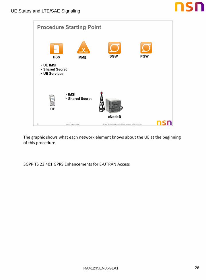
The graphic shows what each network element knows about the UE at the beginning of this procedure.
3GPP TS 23.401 GPRS Enhancements for E-UTRAN Access

RA41235EN06GLA1
UE States and LTE/SAE Signaling
27
The diagram above illustrates UE Initial Access from an RRC-IDLE state.
If the UE supports CS fallback, or the UE is configured to support IMS voice, or both, the UE shall include the information element "Voice domain preference and UE's usage setting" in Attach Request, Tracking Area Update Request and Routing Area Update Request messages. The purpose of this information element is to signal to the network the UE's usage setting and voice domain preference for E-UTRAN. The UE's usage setting indicates whether the UE behaves in a voice centric or data centric way (as defined in TS 23.221). The voice domain preference for E-UTRAN indicates whether the UE is configured as CS Voice only, CS Voice preferred and IMS PS Voice as secondary, IMS PS Voice preferred and CS Voice as secondary, or IMS PS Voice only (as defined in TS 23.221).
a.Depending on operator's configuration, the UE's usage setting and voice domain preference for E-UTRAN can be used by the network to choose RAT/Frequency Selection Priority(RFSP) Index in use. As an example, this enables the enforcement of selective idle mode camping over GERAN/UTRAN for voice centric UEs relying on CS Fallback for voice support in E-UTRAN.
b.For an Emergency Attach the UE shall set both the Attach Type and the Request Type to "Emergency" and the IMSI shall be included if the UE does not have a valid GUTI or a valid P-TMSI available. The IMEI shall be included when the UE has no IMSI, no valid GUTI and no valid P-TMSI.
c.Closed Subscriber Group identifies a group of subscribers who are permitted to access one or more CSG cells of the PLMN as a member of the CSG for a HeNB.

RA41235EN06GLA1
UE States and LTE/SAE Signaling
28
Steps
1. UE sends a Random Access Preamble on the PRACH. eNodeB sends a Random Access Response on PDSCH. The RAR contains the RA Preamble code, temporary C-RNTI, timing advance, and an initial UL grant. UE sends an RRC Connection Request to eNodeB on the PUSCH. eNodeB sends an RRC Connection Setup request on the PDSCH.
2. UE sends an RRC Connection Setup Complete containing a NAS Attach Request to eNodeB on PUSCH. The Attach Request contains IMSI, UE Network Capability, PDN Type, Protocol Configuration Options, and the selected network.
3. The eNodeB sends an S1AP INITIAL UE MESSAGE containing a NAS Attach Request to the MME. Attach Request contains the Selected Network, and Tracking Area Identity and E-UTRAN Global Cell Identity (TAI+ECGI) of the cell from where it received the message to the MME.
4. The MME and UE will perform an authentication handshake. Initial authentication key information is stored in the UE and HSS.
5. The MME will update the location with the HSS.
6. The HSS will respond with update location response with the MME.
RA41235EN06GLA1
UE States and LTE/SAE Signaling
29
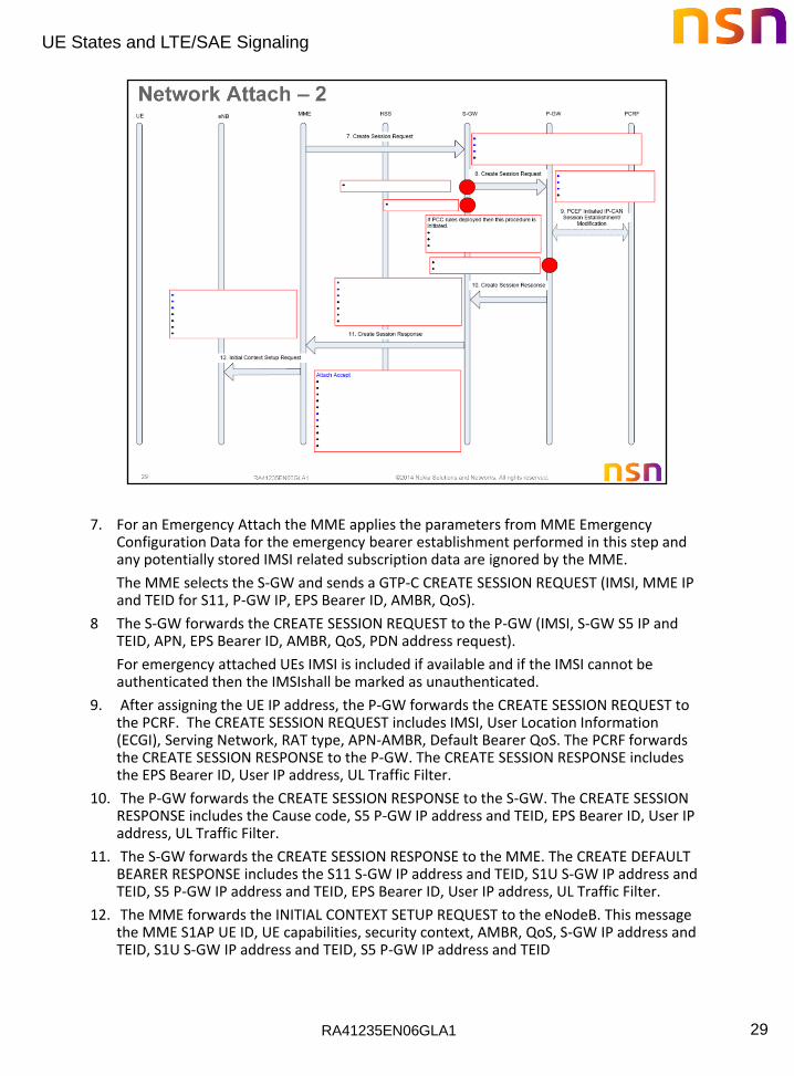
7. For an Emergency Attach the MME applies the parameters from MME Emergency Configuration Data for the emergency bearer establishment performed in this step and any potentially stored IMSI related subscription data are ignored by the MME.
The MME selects the S-GW and sends a GTP-C CREATE SESSION REQUEST (IMSI, MME IP and TEID for S11, P-GW IP, EPS Bearer ID, AMBR, QoS).
8 The S-GW forwards the CREATE SESSION REQUEST to the P-GW (IMSI, S-GW S5 IP and TEID, APN, EPS Bearer ID, AMBR, QoS, PDN address request).
For emergency attached UEs IMSI is included if available and if the IMSI cannot be authenticated then the IMSIshall be marked as unauthenticated.
9. After assigning the UE IP address, the P-GW forwards the CREATE SESSION REQUEST to the PCRF. The CREATE SESSION REQUEST includes IMSI, User Location Information (ECGI), Serving Network, RAT type, APN-AMBR, Default Bearer QoS. The PCRF forwards the CREATE SESSION RESPONSE to the P-GW. The CREATE SESSION RESPONSE includes the EPS Bearer ID, User IP address, UL Traffic Filter.
10. The P-GW forwards the CREATE SESSION RESPONSE to the S-GW. The CREATE SESSION RESPONSE includes the Cause code, S5 P-GW IP address and TEID, EPS Bearer ID, User IP address, UL Traffic Filter.
11. The S-GW forwards the CREATE SESSION RESPONSE to the MME. The CREATE DEFAULT BEARER RESPONSE includes the S11 S-GW IP address and TEID, S1U S-GW IP address and TEID, S5 P-GW IP address and TEID, EPS Bearer ID, User IP address, UL Traffic Filter.
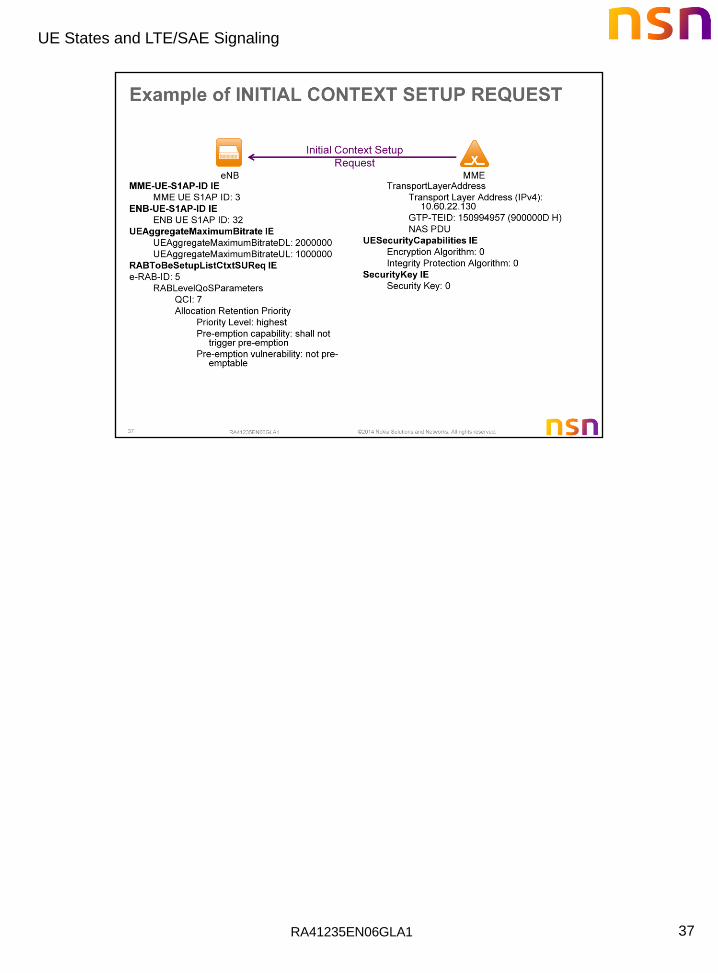
12. The MME forwards the INITIAL CONTEXT SETUP REQUEST to the eNodeB. This message the MME S1AP UE ID, UE capabilities, security context, AMBR, QoS, S-GW IP address and TEID, S1U S-GW IP address and TEID, S5 P-GW IP address and TEID

RA41235EN06GLA1
UE States and LTE/SAE Signaling
30
For an emergency attached UE, i.e. for UEs that have only emergency EPS bearers established, there is no AS security context information included in the S1 control messages and there is no NAS level security when the UE cannot be authenticated. The Emergency Service Support indicator informs the UE that Emergency bearer services are supported, i.e. the UE is allowed to request PDN connectivity for emergency services.
13 The RRC RECONFIG configures Data Radio Bearer PDCP/RLC/MAC/PHY parameters, and measurement configurations.
14 The RRC CONNECTION RECONFIG COMPLETE confirms that the RRC Connection Reconfiguration has been completed.
15 The INITIAL CONTEXT SETUP RESP carries the eNodeB & MME S1AP UE ID, eNodeB IP & TEID (S1-U), EPS Bearer ID.
16 The UE sends the NAS Attach Complete message (EPS Bearer Identity,
NAS sequence number, NAS-MAC).
17 The eNodeB forwards the NAS Attach Complete message to the new MME in an Uplink NAS Transport message. After the Attach Accept message and once the UE has obtained a PDN Address, the UE can then send uplink packets towards the eNodeB which will then be tunnelled to the S-GW and P-GW.
18 UL Packets can now be tunnelled towards the P-GW.
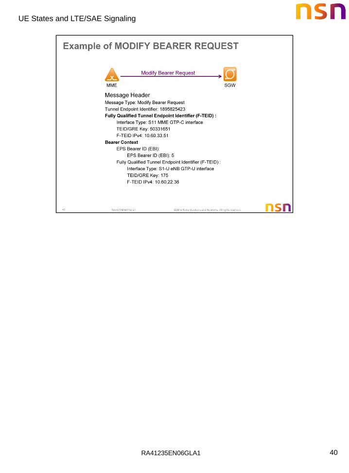
19 The MME sends an MODIFY BEARER REQ to the S-GW (eNodeB IP & TEID, EPS Bearer ID).
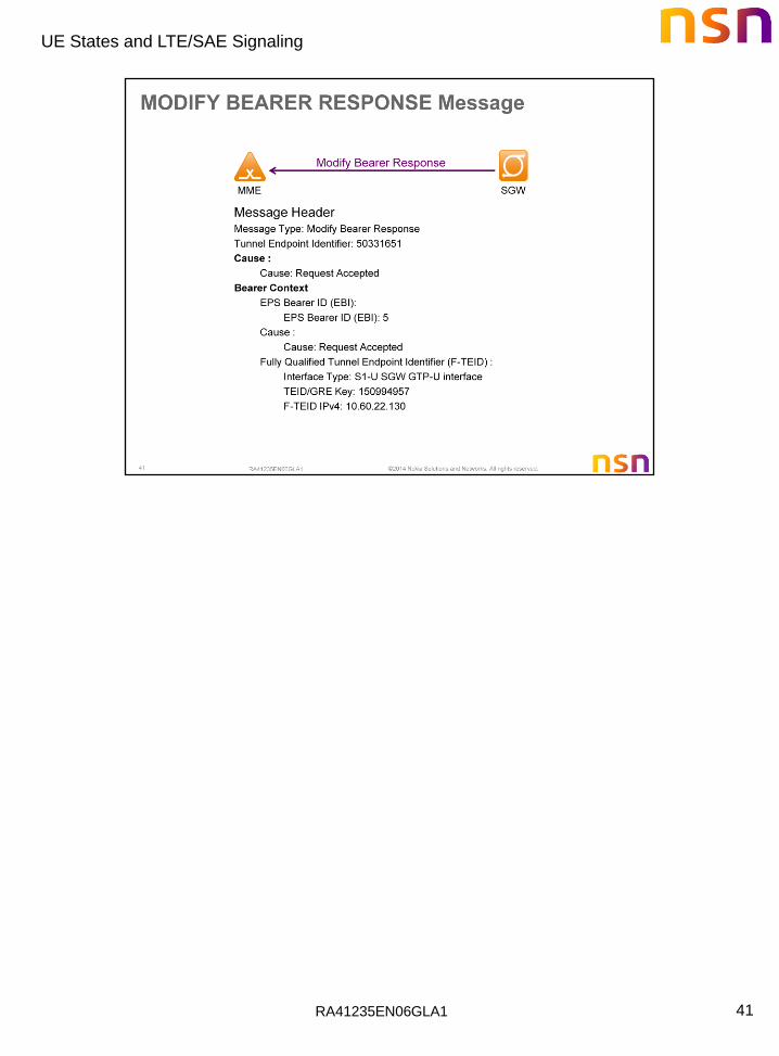
20 The S-GW returns an MODIFY BEARER RESP. - Includes Cause, EPS Bearer ID.
21 DL Packets can now be tunnelled towards the Ue.
RA41235EN06GLA1
UE States and LTE/SAE Signaling
31
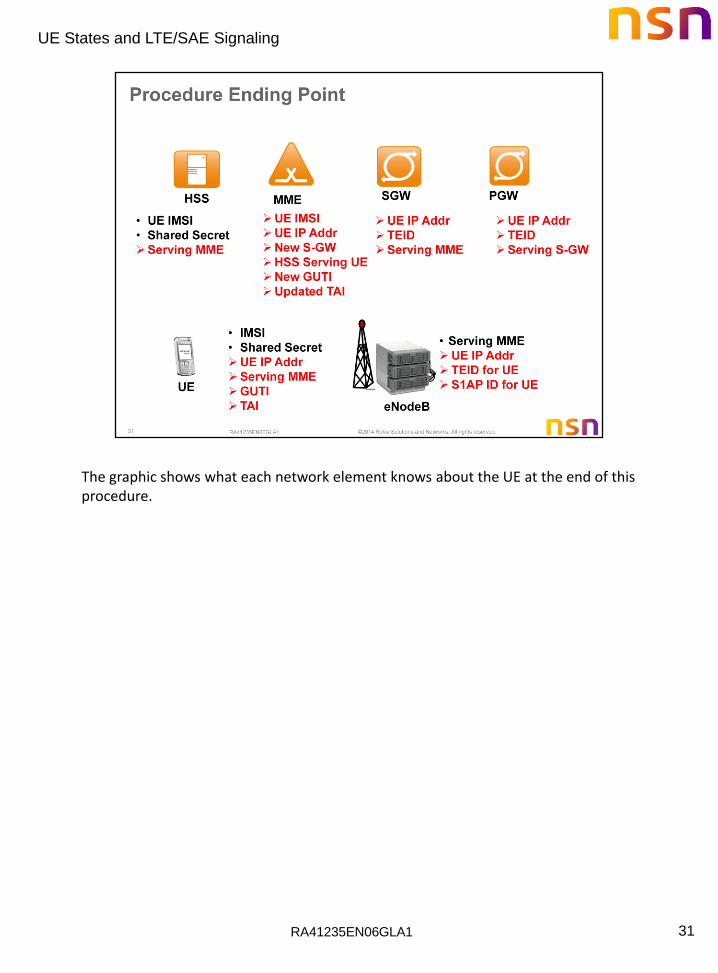
The graphic shows what each network element knows about the UE at the end of this procedure.

RA41235EN06GLA1
UE States and LTE/SAE Signaling
32
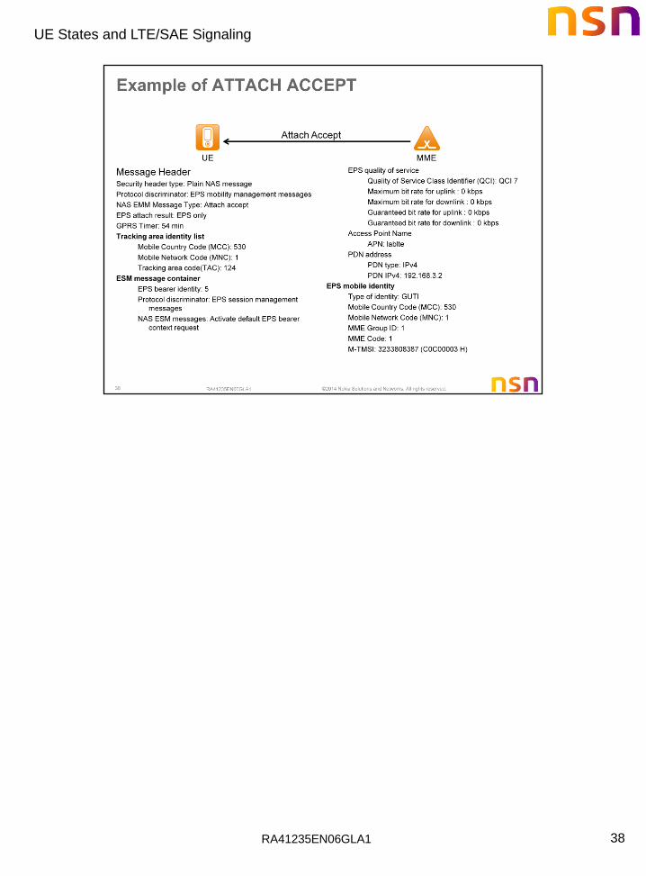
The MME shall initiate the default bearer context activation procedure by sending an ACTIVATE DEFAULT EPS BEARER CONTEXT REQUEST message. When the default bearer is activated as part of the attach procedure, the MME shall send the ACTIVATE DEFAULT EPS BEARER CONTEXT REQUEST message together with ATTACH ACCEPT.
When the default bearer is activated as the response to a stand-alone PDN CONNECTIVITY REQUEST message apart from the attach procedure, the MME shall send the ACTIVATE DEFAULT EPS BEARER CONTEXT REQUEST message alone.
The MME shall assign and include an EPS bearer identity in the ACTIVATE DEFAULT EPS BEARER CONTEXT REQUEST message. The MME shall retrieve the Procedure Transaction Identity (PTI) from the PDN CONNECTIVITY REQUEST message and include it in the ACTIVATE DEFAULT EPS BEARER CONTEXT REQUEST message. Both the network identifier part and the operator identifier part shall be included in the Access Point Name IE.

RA41235EN06GLA1
UE States and LTE/SAE Signaling
33

RA41235EN06GLA1
UE States and LTE/SAE Signaling
34

RA41235EN06GLA1
UE States and LTE/SAE Signaling
35

RA41235EN06GLA1
UE States and LTE/SAE Signaling
36
RA41235EN06GLA1
UE States and LTE/SAE Signaling
37
RA41235EN06GLA1
UE States and LTE/SAE Signaling
38

RA41235EN06GLA1
UE States and LTE/SAE Signaling
39
RA41235EN06GLA1
UE States and LTE/SAE Signaling
40
RA41235EN06GLA1
UE States and LTE/SAE Signaling
41
RA41235EN06GLA1
UE States and LTE/SAE Signaling
42
RA41235EN06GLA1
UE States and LTE/SAE Signaling
43

RA41235EN06GLA1
UE States and LTE/SAE Signaling
44
1. The eNB can send the message S1 RELEASE REQUEST (S1-AP) to the MME to request the release of all EUTRAN resources for a UE. The message can for instance be triggered by detection of a period of inactivity.
2. When the MME gets a trigger to release the UE from EUTRAN, it will release the S1 tunnels allocated for the SAE bearers of the UE. This is done by sending an UPDATE BEARER REQUEST message (GTP-C) to the Serving GW. In the message the indication of the release of the S1 resources.
3. In parallel to the previous step the MME will send the S1-AP message S1 RELEASE COMMAND to the eNB. It will trigger the release of the UE on the air interface with message RRC CONNECTION RELEASE (RRC). This will bring the UE to RRC_IDLE state and with that also to ECM_IDLE state. The UE acknowledges with RRC CONNECTION RELEASE ACK.
RA41235EN06GLA1
UE States and LTE/SAE Signaling
45

RA41235EN06GLA1
UE States and LTE/SAE Signaling
46
The MME shall initiate the dedicated bearer context activation procedure by sending an ACTIVATE DEDICATED EPS BEARER CONTEXT REQUEST message.
The MME allocates the EPS bearer identity and includes it in the ACTIVATE DEDICATED EPS BEARER CONTEXT REQUEST message. The MME shall include the EPS bearer identity of the associated default bearer as the linked EPS bearer identity in the ACTIVATE DEDICATED EPS BEARER CONTEXT REQUEST message. The ACTIVATE DEDICATED EPS BEARER CONTEXT REQUEST message shall also include a procedure transaction identity (PTI), if this procedure was initiated by a UE requested bearer resource allocation procedure or a UE requested bearer resource modification procedure.

RA41235EN06GLA1
UE States and LTE/SAE Signaling
47
1. If dynamic PCC is deployed, the PCRF sends a PCC decision provision (QoS policy) message to the PDN GW.
2. The PDN GW uses this QoS policy to assign the EPS Bearer QoS, i.e., it assigns the values to the bearer level QoS parameters QCI, ARP, GBR and MBR. The PGW generates a Charging Id for the dedicated bearer. The PDN GW sends a Create Bearer Request message (IMSI, PTI, EPS Bearer QoS, TFT, S5/S8 TEID, Charging Id, LBI, Protocol Configuration Options) to the Serving GW, the Linked EPS Bearer Identity (LBI) is the EPS Bearer Identity of the default bearer.
3. The Serving GW sends the Create Bearer Request (IMSI, PTI, EPS Bearer QoS, TFT, S1-TEID, PDN GW TEID (GTP-based S5/S8), LBI, Protocol Configuration Options) message to the MME. If the UE is in ECM-IDLE state the MME will trigger the Network Triggered Service Request from step 3. In that case the following steps 4-7 may be combined into Network Triggered Service Request procedure or be performed standalone.
4. The MME selects an EPS Bearer Identity, which has not yet been assigned to the UE. The MME then builds a Session Management Request including the PTI, TFT, EPS Bearer QoS parameters (excluding ARP), Protocol Configuration Options, the EPS Bearer Identity and the Linked EPS Bearer Identity (LBI). The MME then signals the Bearer Setup Request (EPS Bearer Identity, EPS Bearer QoS, Session Management Request, S1-TEID) message to the eNodeB.
RA41235EN06GLA1
UE States and LTE/SAE Signaling
48
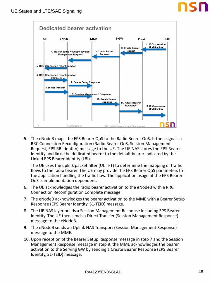
5. The eNodeB maps the EPS Bearer QoS to the Radio Bearer QoS. It then signals a RRC Connection Reconfiguration (Radio Bearer QoS, Session Management Request, EPS RB Identity) message to the UE. The UE NAS stores the EPS Bearer Identity and links the dedicated bearer to the default bearer indicated by the Linked EPS Bearer Identity (LBI).
The UE uses the uplink packet filter (UL TFT) to determine the mapping of traffic flows to the radio bearer. The UE may provide the EPS Bearer QoS parameters to the application handling the traffic flow. The application usage of the EPS Bearer QoS is implementation dependent.
6. The UE acknowledges the radio bearer activation to the eNodeB with a RRC Connection Reconfiguration Complete message.
7. The eNodeB acknowledges the bearer activation to the MME with a Bearer Setup Response (EPS Bearer Identity, S1-TEID) message.
8. The UE NAS layer builds a Session Management Response including EPS Bearer Identity. The UE then sends a Direct Transfer (Session Management Response) message to the eNodeB.
9. The eNodeB sends an Uplink NAS Transport (Session Management Response) message to the MME.
10. Upon reception of the Bearer Setup Response message in step 7 and the Session Management Response message in step 9, the MME acknowledges the bearer activation to the Serving GW by sending a Create Bearer Response (EPS Bearer Identity, S1-TEID) message.
RA41235EN06GLA1
UE States and LTE/SAE Signaling
49
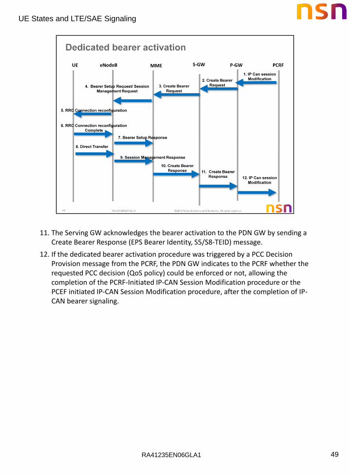
11. The Serving GW acknowledges the bearer activation to the PDN GW by sending a Create Bearer Response (EPS Bearer Identity, S5/S8-TEID) message.
12. If the dedicated bearer activation procedure was triggered by a PCC Decision Provision message from the PCRF, the PDN GW indicates to the PCRF whether the requested PCC decision (QoS policy) could be enforced or not, allowing the completion of the PCRF-Initiated IP-CAN Session Modification procedure or the PCEF initiated IP-CAN Session Modification procedure, after the completion of IP-CAN bearer signaling.

RA41235EN06GLA1
UE States and LTE/SAE Signaling
50

RA41235EN06GLA1
UE States and LTE/SAE Signaling
51
1. UE sends a Random Access Preamble on the PRACH. eNodeB sends a Random Access Response on PDSCH. The RAR contains the RA Preamble code, temporary C-RNTI, timing advance, and an initial UL grant. UE sends an RRC Connection Request to eNodeB on the PUSCH. eNodeB sends an RRC Connection Setup request on the PDSCH
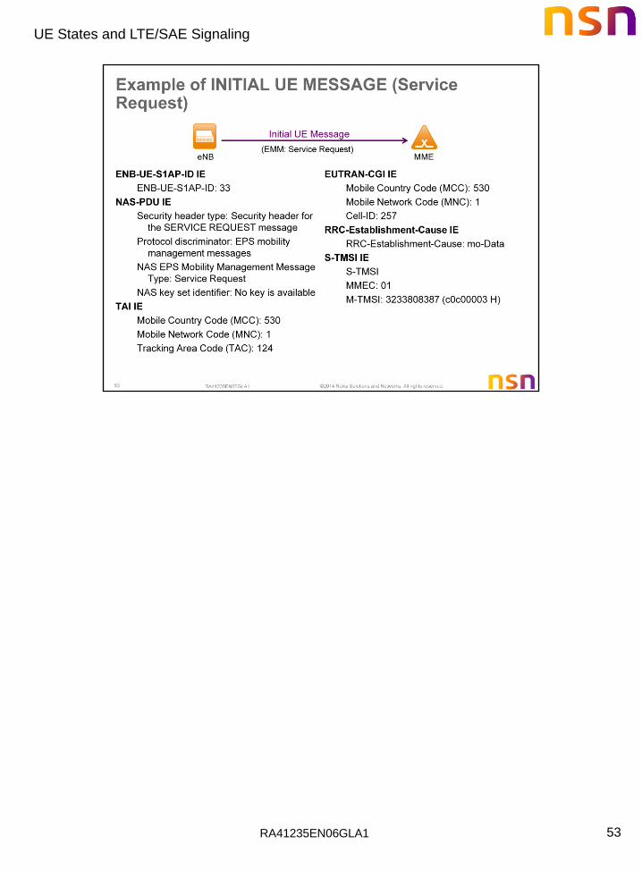
2. The UE sends NAS SERVICE REQUEST (S-TMSI) message toward the MME encapsulated in an RRC message to the eNodeB.
3. The eNodeB forwards the NAS message to the MME. The NAS message is encapsulated in an S1-AP: INITIAL UE MESSAGE (NAS message, TAI+ECGI of the serving cell).
4. If needed, UE authentication may be performed.
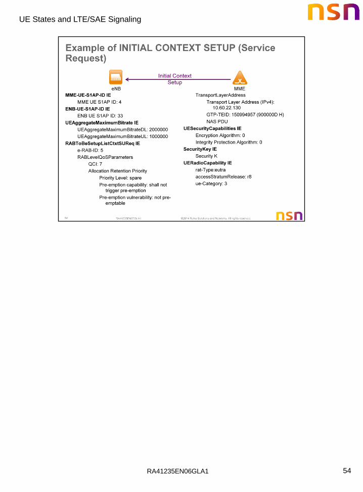
5. The MME sends S1-AP INITIAL CONTEXT SETUP REQUEST (S-GW address, S1-TEID(s) (UL), Bearer QoS(s), Security Context, MME Signaling Connection Id, Handover Restriction List) to the eNodeB. This step activates the radio and S1 bearers for all the active EPS Bearers. The eNodeB stores the Security Context, MME Signaling Connection Id, Bearer QoS profile(s) and S1-TEID(s).
6. The eNodeB performs the radio bearer establishment procedure. When the user plane radio bearers are setup the Service Request is complete and EPS bearer state is synchronized between the UE and the network.
7. The uplink data from the UE can now be forwarded by eNodeB to the Serving GW. The eNodeB sends the uplink data to the S-GW address and TEID provided in the step 5.
RA41235EN06GLA1
UE States and LTE/SAE Signaling
52
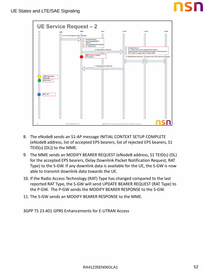
8. The eNodeB sends an S1-AP message INITIAL CONTEXT SETUP COMPLETE (eNodeB address, list of accepted EPS bearers, list of rejected EPS bearers, S1 TEID(s) (DL)) to the MME.
9. The MME sends an MODIFY BEARER REQUEST (eNodeB address, S1 TEID(s) (DL) for the accepted EPS bearers, Delay Downlink Packet Notification Request, RAT Type) to the S-GW. If any downlink data is available for the UE, the S-GW is now able to transmit downlink data towards the UE.
10. If the Radio Access Technology (RAT) Type has changed compared to the last reported RAT Type, the S-GW will send UPDATE BEARER REQUEST (RAT Type) to the P-GW. The P-GW sends the MODIFY BEARER RESPONSE to the S-GW.
11. The S-GW sends an MODIFY BEARER RESPONSE to the MME.
3GPP TS 23.401 GPRS Enhancements for E-UTRAN Access
RA41235EN06GLA1
UE States and LTE/SAE Signaling
53
RA41235EN06GLA1
UE States and LTE/SAE Signaling
54

RA41235EN06GLA1
UE States and LTE/SAE Signaling
55

RA41235EN06GLA1
UE States and LTE/SAE Signaling
56
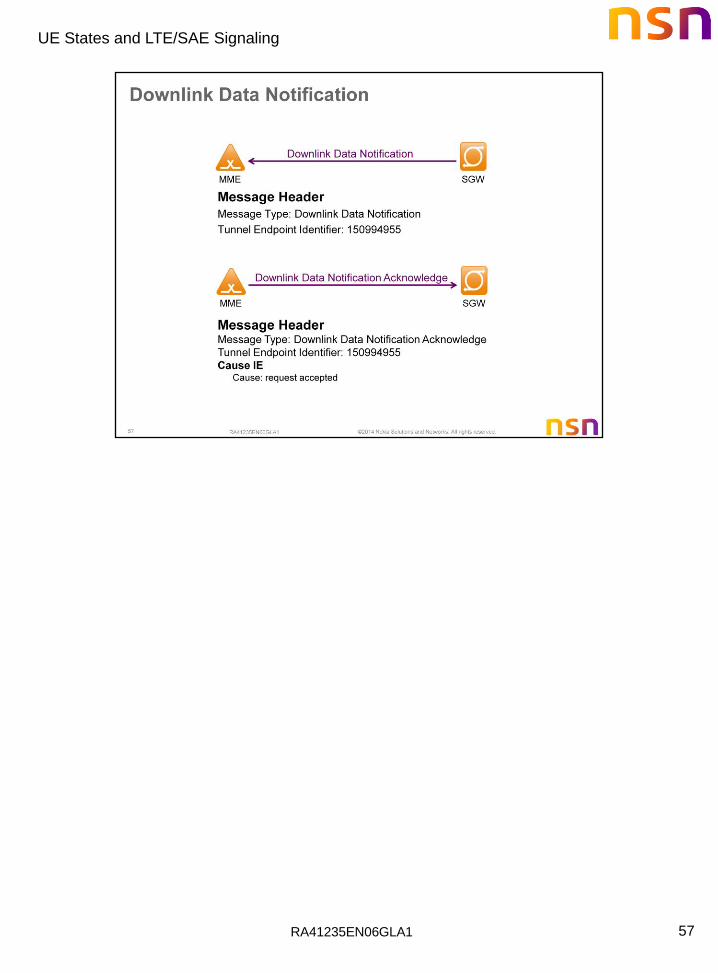
When the S-GW receives data for a UE, it buffers the data and identifies which MME is serving the UE.
1. The S-GW sends a DOWNLINK DATA NOTIFICATION message to the MME which has control plane connectivity for the given UE.
2. The MME responds to the S-GW with a DOWNLINK DATA NOTIFICATION ACK message.
3. If the UE is registered in the MME, the MME sends a PAGING message (NAS Paging ID, TAI(s), and Paging DRX ID) to each eNodeB belonging to the Tracking Area(s) in which the UE is registered.
4. The eNodeBs (in the specified Tracking Area(s)), receive the PAGING messages from the MME and page the UE.
5. When the PAGING message is received by the UE, it sends a PAGING RESPONSE back to the eNodeB and initiates the UE Triggered Service Request procedure we just discussed.
6. The S-GW sends a STOP PAGING message to the MME.
7. The buffered data is sent towards the UE.
3GPP TS 23.401 GPRS Enhancements for E-UTRAN Access
RA41235EN06GLA1
UE States and LTE/SAE Signaling
57

RA41235EN06GLA1
UE States and LTE/SAE Signaling
58
RA41235EN06GLA1
UE States and LTE/SAE Signaling
59

RA41235EN06GLA1
UE States and LTE/SAE Signaling
60
RA41235EN06GLA1
UE States and LTE/SAE Signaling
61
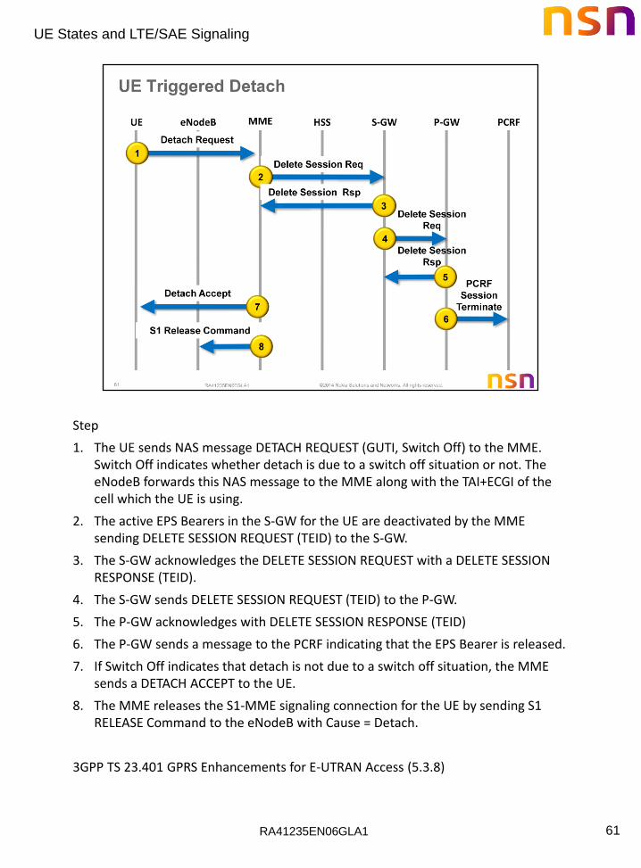
Step
1. The UE sends NAS message DETACH REQUEST (GUTI, Switch Off) to the MME. Switch Off indicates whether detach is due to a switch off situation or not. The eNodeB forwards this NAS message to the MME along with the TAI+ECGI of the cell which the UE is using.
2. The active EPS Bearers in the S-GW for the UE are deactivated by the MME sending DELETE SESSION REQUEST (TEID) to the S-GW.
3. The S-GW acknowledges the DELETE SESSION REQUEST with a DELETE SESSION RESPONSE (TEID).
4. The S-GW sends DELETE SESSION REQUEST (TEID) to the P-GW.
5. The P-GW acknowledges with DELETE SESSION RESPONSE (TEID)
6. The P-GW sends a message to the PCRF indicating that the EPS Bearer is released.
7. If Switch Off indicates that detach is not due to a switch off situation, the MME sends a DETACH ACCEPT to the UE.
8. The MME releases the S1-MME signaling connection for the UE by sending S1 RELEASE Command to the eNodeB with Cause = Detach.
3GPP TS 23.401 GPRS Enhancements for E-UTRAN Access (5.3.8)
RA41235EN06GLA1
UE States and LTE/SAE Signaling
62
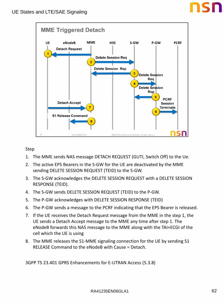
Step
1. The MME sends NAS message DETACH REQUEST (GUTI, Switch Off) to the Ue.
2. The active EPS Bearers in the S-GW for the UE are deactivated by the MME sending DELETE SESSION REQUEST (TEID) to the S-GW.
3. The S-GW acknowledges the DELETE SESSION REQUEST with a DELETE SESSION RESPONSE (TEID).
4. The S-GW sends DELETE SESSION REQUEST (TEID) to the P-GW.
5. The P-GW acknowledges with DELETE SESSION RESPONSE (TEID)
6. The P-GW sends a message to the PCRF indicating that the EPS Bearer is released.
7. If the UE receives the Detach Request message from the MME in the step 1, the UE sends a Detach Accept message to the MME any time after step 1. The eNodeB forwards this NAS message to the MME along with the TAI+ECGI of the cell which the UE is using
8. The MME releases the S1-MME signaling connection for the UE by sending S1 RELEASE Command to the eNodeB with Cause = Detach.
3GPP TS 23.401 GPRS Enhancements for E-UTRAN Access (5.3.8)
RA41235EN06GLA1
UE States and LTE/SAE Signaling
63

RA41235EN06GLA1
UE States and LTE/SAE Signaling
64
RA41235EN06GLA1
UE States and LTE/SAE Signaling
65
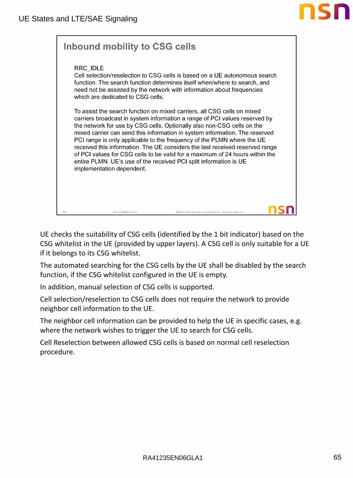
UE checks the suitability of CSG cells (identified by the 1 bit indicator) based on the CSG whitelist in the UE (provided by upper layers). A CSG cell is only suitable for a UE if it belongs to its CSG whitelist.
The automated searching for the CSG cells by the UE shall be disabled by the search function, if the CSG whitelist configured in the UE is empty.
In addition, manual selection of CSG cells is supported.
Cell selection/reselection to CSG cells does not require the network to provide neighbor cell information to the UE.
The neighbor cell information can be provided to help the UE in specific cases, e.g. where the network wishes to trigger the UE to search for CSG cells.
Cell Reselection between allowed CSG cells is based on normal cell reselection procedure.
RA41235EN06GLA1
UE States and LTE/SAE Signaling
66
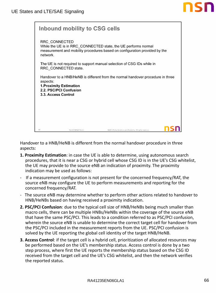
Handover to a HNB/HeNB is different from the normal handover procedure in three aspects:
1. Proximity Estimation: in case the UE is able to determine, using autonomous search procedures, that it is near a CSG or hybrid cell whose CSG ID is in the UE’s CSG whitelist, the UE may provide to the source eNB an indication of proximity. The proximity indication may be used as follows:
- If a measurement configuration is not present for the concerned frequency/RAT, the source eNB may configure the UE to perform measurements and reporting for the concerned frequency/RAT.
- The source eNB may determine whether to perform other actions related to handover to HNB/HeNBs based on having received a proximity indication.
2. PSC/PCI Confusion: due to the typical cell size of HNB/HeNBs being much smaller than macro cells, there can be multiple HNBs/HeNBs within the coverage of the source eNB that have the same PSC/PCI. This leads to a condition referred to as PSC/PCI confusion, wherein the source eNB is unable to determine the correct target cell for handover from the PSC/PCI included in the measurement reports from the UE. PSC/PCI confusion is solved by the UE reporting the global cell identity of the target HNB/HeNB.
3. Access Control: if the target cell is a hybrid cell, prioritization of allocated resources may be performed based on the UE’s membership status. Access control is done by a two step process, where first the UE reports the membership status based on the CSG ID received from the target cell and the UE’s CSG whitelist, and then the network verifies the reported status.

RA41235EN06GLA1
UE States and LTE/SAE Signaling
67

RA41235EN06GLA1
UE States and LTE/SAE Signaling
68
shows a simplified version of the attach procedure for the RN. The procedure is the same as the normal UE attach procedure [with the exception that:
− The DeNB has been made aware of which MMEs support RN functionality via the S1 Setup Response message earlier received from the MMEs;
− The RN sends an RN indication to the DeNB during RRC connection establishment;
− After receiving the RN indication from the RN, the DeNB sends the RN indicator and the IP address of the S-GW/P-GW function embedded in the DeNB to an MME supporting RN functionality within the Initial UE Message;
− MME selects S-GW/P-GW for the RN based on the IP address included in the Initial UE Message;
− During the attach procedure, the EPC checks if the RN is authorized for relay operation; only if the RN is authorized, the EPC accepts the attach and sets up a context with the DeNB; otherwise the EPC rejects the attach.
− The RN is preconfigured with information about which cells (DeNBs) it is allowed to access.
RA41235EN06GLA1
UE States and LTE/SAE Signaling
69
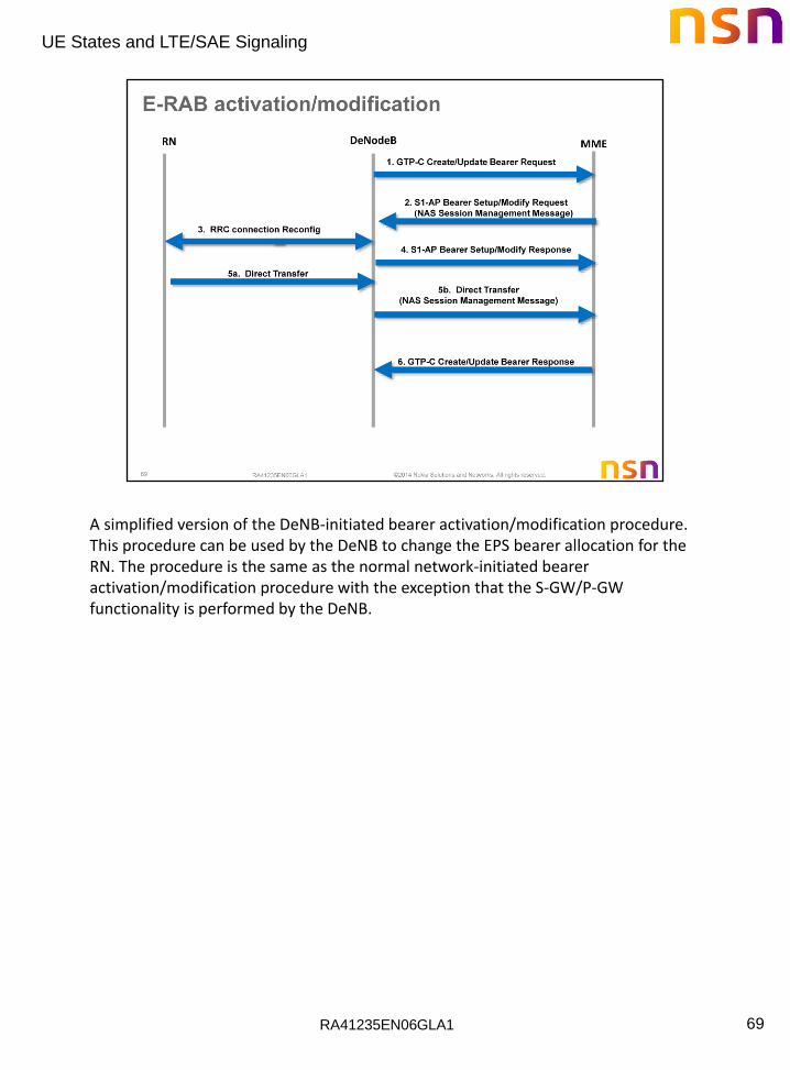
A simplified version of the DeNB-initiated bearer activation/modification procedure. This procedure can be used by the DeNB to change the EPS bearer allocation for the RN. The procedure is the same as the normal network-initiated bearer activation/modification procedure with the exception that the S-GW/P-GW functionality is performed by the DeNB.
RA41235EN06GLA1
UE States and LTE/SAE Signaling
70
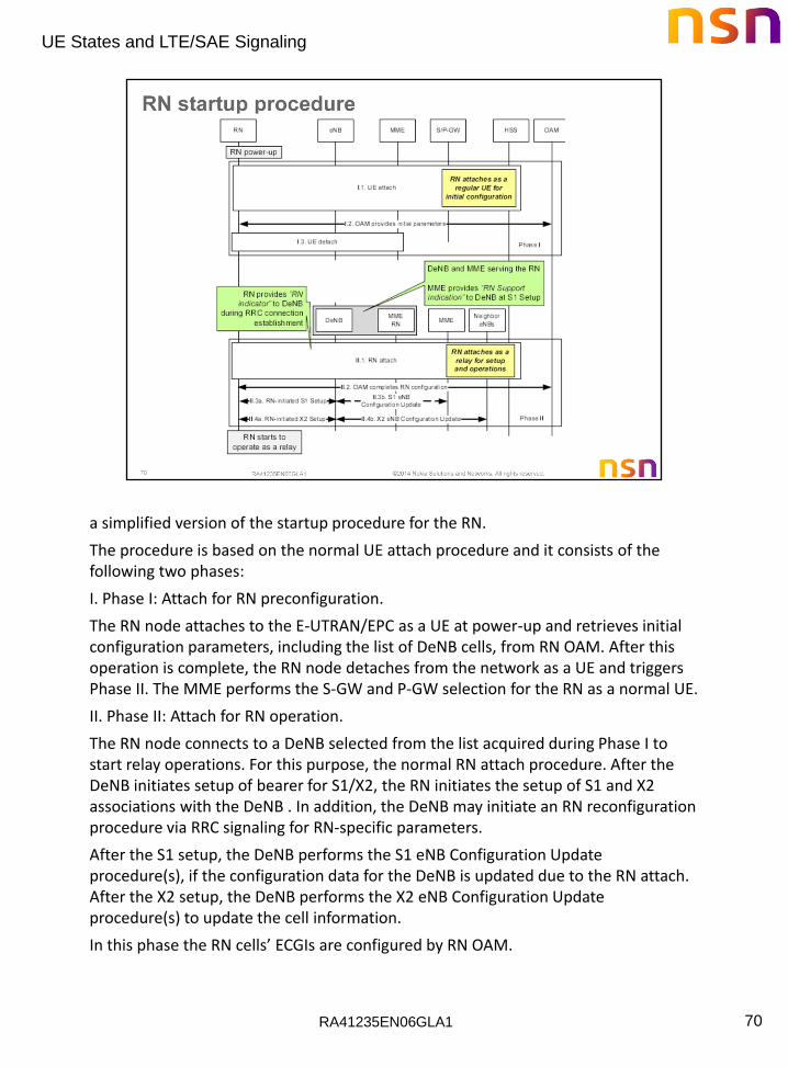
a simplified version of the startup procedure for the RN.
The procedure is based on the normal UE attach procedure and it consists of the following two phases:
I. Phase I: Attach for RN preconfiguration.
The RN node attaches to the E-UTRAN/EPC as a UE at power-up and retrieves initial configuration parameters, including the list of DeNB cells, from RN OAM. After this operation is complete, the RN node detaches from the network as a UE and triggers Phase II. The MME performs the S-GW and P-GW selection for the RN as a normal UE.
II. Phase II: Attach for RN operation.
The RN node connects to a DeNB selected from the list acquired during Phase I to start relay operations. For this purpose, the normal RN attach procedure. After the DeNB initiates setup of bearer for S1/X2, the RN initiates the setup of S1 and X2 associations with the DeNB . In addition, the DeNB may initiate an RN reconfiguration procedure via RRC signaling for RN-specific parameters.
After the S1 setup, the DeNB performs the S1 eNB Configuration Update procedure(s), if the configuration data for the DeNB is updated due to the RN attach. After the X2 setup, the DeNB performs the X2 eNB Configuration Update procedure(s) to update the cell information.
In this phase the RN cells’ ECGIs are configured by RN OAM.
RA41235EN06GLA1
UE States and LTE/SAE Signaling
71

RA41235EN06GLA1
UE States and LTE/SAE Signaling
72
Let’s take a brief look at the user security methods employed in LTE.
User data and RRC signaling between the UE and the eNodeB is protected by ciphering and integrity methods. The security keys used are forwarded to the eNodeB by the MME to the eNodeB after the Universal Subscriber Identity Module (USIM) and the MME have been authenticated. NAS signaling is also cipher and integrity protected between the UE and MME using separate keys.
There are three types of security protections employed within the EPS:
• Ciphering –protects data from being “overheard.” This applies to user data as well as signaling messages.
• Integrity –ensures that the receiving network element is able to verify that the signaling data has not been modified since it was transmitted by the sending network element.
• Mutual Authentication – confirms the UE’s identity to the network, and the network’s identity to the UE.

RA41235EN06GLA1
UE States and LTE/SAE Signaling
73
The 3GPP LTE standard introduces new security keys to ensure the correct protection is applied for the different information flows.
K – secret key permanently stored in the USIM and the HSS.
CK, IK – Ciphering Key and Integrity Key computed in the UE and HSS.
KASME (Access Security Management Entity) – derived by the UE and HSS from CK and IK during the Authentication process. KASME is responsible for establishing and maintaining security associations with UEs based on keys received from the HSS. In LTE, the ASME function is provided by the MME.
KeNB – derived by UE and MME from KASME and is used by the eNodeB to derive the keys for RRC and User Plane traffic.
This key is derived by UE and eNB from KeNB, as well as an identifier for the encryption algorithm.
-KRRCint is a key, which shall only be used for the protection of RRC traffic with a particular integrity algorithm. KRRCint is derived by UE and eNB from KeNB, as well as an identifier for the integrity algorithm.
KRRCenc is a key, which shall only be used for the protection of RRC traffic with a particular encryption algorithm. KRRCenc is derived by UE and eNB from KeNB as well as an identifier for the encryption algorithm.
Next Hop (NH) is used by UE and eNB in the derivation of KeNB* for the provision of "forward security“ NH is derived by UE and MME from KASME and KeNB when the security context is established, or from KASME and previous NH, otherwise.
Next Hop Chaining Count (NCC) is a counter related to NH (i.e. the amount of Key chaining that has been performed) which allow the UE to be synchronized with the eNB and to determine whether the next KeNB* needs to be based on the current KeNB or a fresh NH.
Using those keys, the other keys are produced to ensure integrity and privacy of:
• NAS signaling between the UE and MME
• AS (Access Stratum) signaling between the UE and eNodeB
• User Plane data between UE and S-GW. KUP enc is a key, which shall only be used for the protection of UP traffic with a particular encryption algorithm.
RA41235EN06GLA1
UE States and LTE/SAE Signaling
74
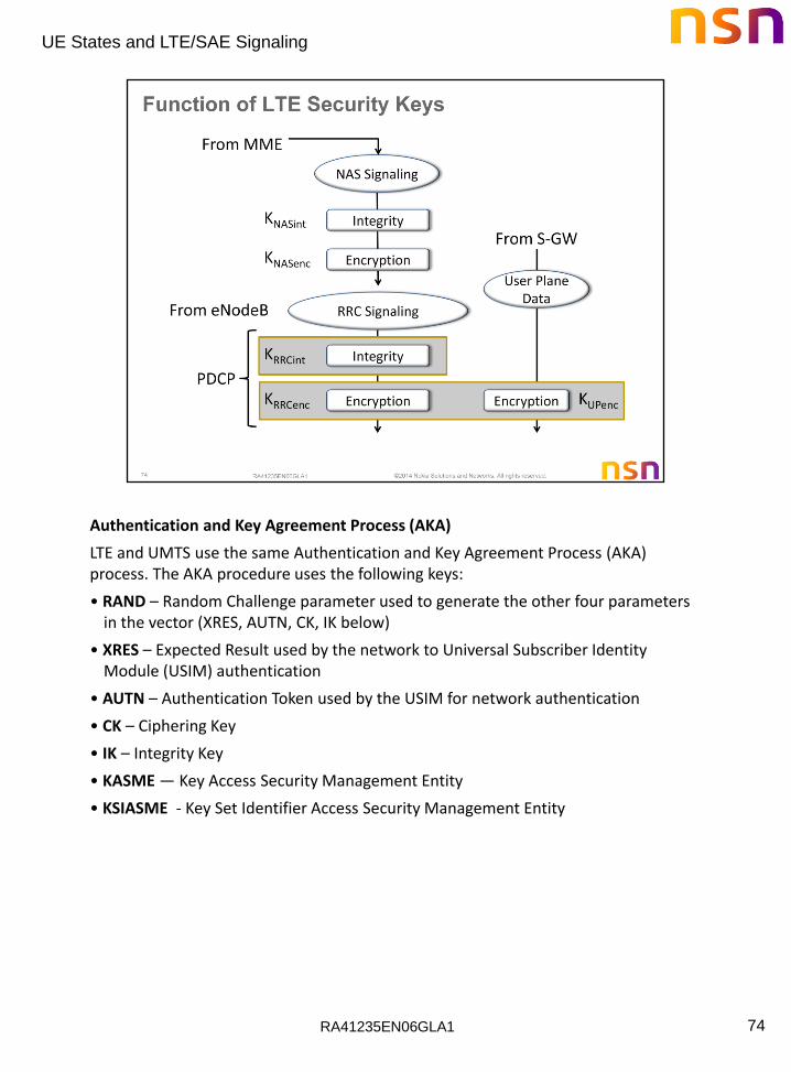
Authentication and Key Agreement Process (AKA)
LTE and UMTS use the same Authentication and Key Agreement Process (AKA) process. The AKA procedure uses the following keys:
• RAND – Random Challenge parameter used to generate the other four parameters in the vector (XRES, AUTN, CK, IK below)
• XRES – Expected Result used by the network to Universal Subscriber Identity Module (USIM) authentication
• AUTN – Authentication Token used by the USIM for network authentication
• CK – Ciphering Key
• IK – Integrity Key
• KASME — Key Access Security Management Entity
• KSIASME - Key Set Identifier Access Security Management Entity
RA41235EN06GLA1
UE States and LTE/SAE Signaling
75
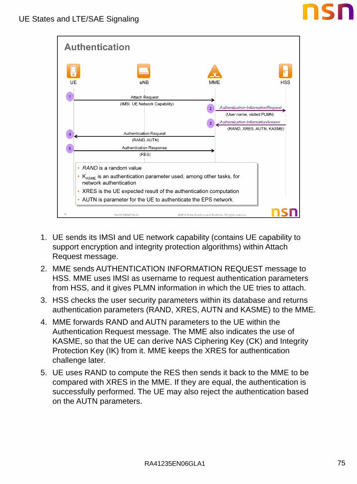
1. UE sends its IMSI and UE network capability (contains UE capability to
support encryption and integrity protection algorithms) within Attach
Request message.
2. MME sends AUTHENTICATION INFORMATION REQUEST message to
HSS. MME uses IMSI as username to request authentication parameters
from HSS, and it gives PLMN information in which the UE tries to attach.
3. HSS checks the user security parameters within its database and returns
authentication parameters (RAND, XRES, AUTN and KASME) to the MME.
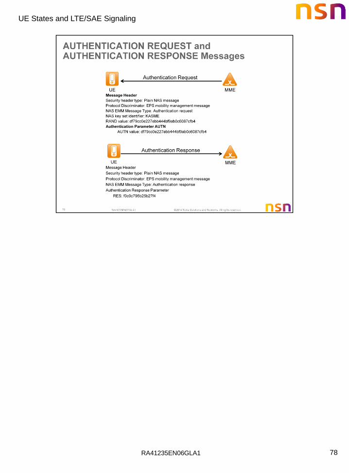
4. MME forwards RAND and AUTN parameters to the UE within the
Authentication Request message. The MME also indicates the use of
KASME, so that the UE can derive NAS Ciphering Key (CK) and Integrity
Protection Key (IK) from it. MME keeps the XRES for authentication
challenge later.
5. UE uses RAND to compute the RES then sends it back to the MME to be
compared with XRES in the MME. If they are equal, the authentication is
successfully performed. The UE may also reject the authentication based
on the AUTN parameters.
RA41235EN06GLA1
UE States and LTE/SAE Signaling
76
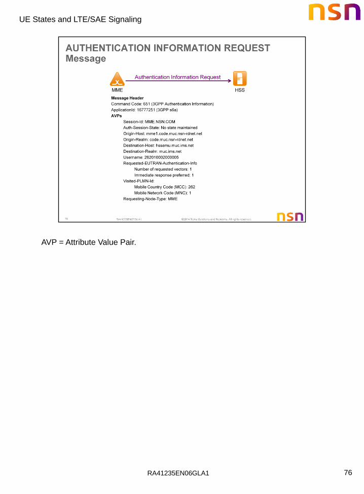
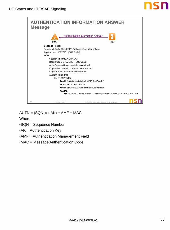
AVP = Attribute Value Pair.
RA41235EN06GLA1
UE States and LTE/SAE Signaling
77
AUTN = (SQN xor AK) + AMF + MAC.
Where,
•SQN = Sequence Number
•AK = Authentication Key
•AMF = Authentication Management Field
•MAC = Message Authentication Code.
RA41235EN06GLA1
UE States and LTE/SAE Signaling
78

RA41235EN06GLA1
UE States and LTE/SAE Signaling
79

RA41235EN06GLA1
UE States and LTE/SAE Signaling
80
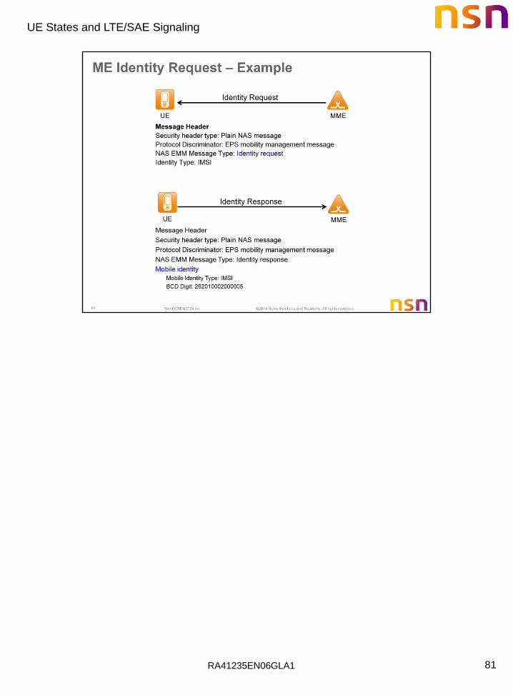
1. The MME sends Identity Request (Identity Type) to the UE.
2. The UE responds with Identity Response (Mobile Identity).
3. If the MME is configured to check the IMEI against the EIR, it sends ME
Identity Check (ME Identity, IMSI) to EIR.
4. The EIR responds with ME Identity Check Ack (Result).
RA41235EN06GLA1
UE States and LTE/SAE Signaling
81
RA41235EN06GLA1
UE States and LTE/SAE Signaling
82

RA41235EN06GLA1
UE States and LTE/SAE Signaling
83

RA41235EN06GLA1
UE States and LTE/SAE Signaling
84