03 escort
184
Introduction 4 Instrument Cluster 10 Warning and control lights 10 Gauges 12 Entertainment Systems 14 AM/FM stereo cassette 14 AM/FM stereo with CD 19 Climate Controls 28 Heater only 28 Manual heating and air conditioning 29 Lights 33 Headlamps 33 Turn signal control 36 Bulb replacement 37 Driver Controls 43 Windshield wiper/washer control 43 Steering wheel adjustment 44 Power windows 44 Mirrors 45 Speed control 45 Locks and Security 51 Keys 51 Locks 51 Anti-theft system 53 Table of Contents 1
Transcript of 03 escort

Introduction 4
Instrument Cluster 10
Warning and control lights 10Gauges 12
Entertainment Systems 14
AM/FM stereo cassette 14AM/FM stereo with CD 19
Climate Controls 28
Heater only 28Manual heating and air conditioning 29
Lights 33
Headlamps 33Turn signal control 36Bulb replacement 37
Driver Controls 43
Windshield wiper/washer control 43Steering wheel adjustment 44Power windows 44Mirrors 45Speed control 45
Locks and Security 51
Keys 51Locks 51Anti-theft system 53
Table of Contents
1

Seating and Safety Restraints 58
Seating 58Safety restraints 60Air bags 69Child restraints 73
Driving 84
Starting 84Brakes 88Transmission operation 91Vehicle loading 99Trailer towing 100
Roadside Emergencies 103
Getting roadside assistance 103Hazard flasher switch 104Fuel pump shut-off switch 104Fuses and relays 105Changing tires 110Jump starting 114Wrecker towing 119
Customer Assistance 120
Reporting safety defects (U.S. only) 129
Cleaning 130
Table of Contents
2
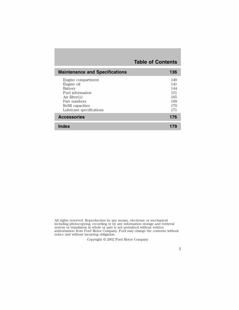
Maintenance and Specifications 136
Engine compartment 140Engine oil 141Battery 144Fuel information 151Air filter(s) 165Part numbers 169Refill capacities 170Lubricant specifications 171
Accessories 176
Index 179
All rights reserved. Reproduction by any means, electronic or mechanicalincluding photocopying, recording or by any information storage and retrievalsystem or translation in whole or part is not permitted without writtenauthorization from Ford Motor Company. Ford may change the contents withoutnotice and without incurring obligation.
Copyright © 2002 Ford Motor Company
Table of Contents
3

CALIFORNIA Proposition 65 Warning
WARNING: Engine exhaust, some of its constituents, andcertain vehicle components contain or emit chemicals known to
the State of California to cause cancer and birth defects or otherreproductive harm. In addition, certain fluids contained in vehicles andcertain products of component wear contain or emit chemicals knownto the State of California to cause cancer and birth defects or otherreproductive harm.
CONGRATULATIONSCongratulations on acquiring your new Ford Motor Company product.Please take the time to get well acquainted with your vehicle by readingthis handbook. The more you know and understand about your vehiclethe greater the safety and pleasure you will derive from driving it.
For more information on Ford Motor Company and its products visit thefollowing website:
• In the United States: www.ford.com
• In Canada: www.ford.ca
• In Mexico: www.ford.com.mx
• In Australia: www.ford.com.au
Additional owner information is given in separate publications.
This Owner’s Guide describes every option and model variant availableand therefore some of the items covered may not apply to yourparticular vehicle. Furthermore, due to printing cycles it may describeoptions before they are generally available.
Remember to pass on the Owner’s Guide when reselling the vehicle. It isan integral part of the vehicle.
Introduction
4

Fuel pump shut-off switch In the event of an accident thesafety switch will automatically cut off the fuel supply to the
engine. The switch can also be activated through sudden vibration (e.g.collision when parking). To reset the switch, refer to the Fuel pumpshut-off switch in the Roadside emergencies chapter.
SAFETY AND ENVIRONMENT PROTECTION
Warning symbols in this guide
How can you reduce the risk of personal injury and prevent possibledamage to others, your vehicle and its equipment? In this guide, answersto such questions are contained in comments highlighted by the warningtriangle symbol. These comments should be read and observed.
Warning symbols on your vehicle
When you see this symbol, it isimperative that you consult therelevant section of this guide beforetouching or attempting adjustmentof any kind.
Protecting the environmentWe must all play our part inprotecting the environment. Correctvehicle usage and the authorizeddisposal of waste cleaning andlubrication materials are significantsteps towards this aim. Information in this respect is highlighted in thisguide with the tree symbol.
Introduction
5

BREAKING-IN YOUR VEHICLEYour vehicle does not need an extensive break-in. Try not to drivecontinuously at the same speed for the first 1,600 km (1,000 miles) ofnew vehicle operation. Vary your speed to allow parts to adjustthemselves to other parts.
Drive your new vehicle at least 800 km (500 miles) before towing atrailer.
Do not add friction modifier compounds or special break-in oils duringthe first few thousand kilometers (miles) of operation, since theseadditives may prevent piston ring seating. See Engine oil in theMaintenance and care chapter for more information on oil usage.
SPECIAL NOTICES
Emission warrantyThe New Vehicle Limited Warranty includes Bumper-to-BumperCoverage, Safety Restraint Coverage, Corrosion Coverage, and 7.3LPower Stroke Diesel Engine Coverage. In addition, your vehicle is eligiblefor Emissions Defect and Emissions Performance Warranties. For adetailed description of what is covered and what is not covered, refer tothe Warranty Guide that is provided to you along with your Owner’sGuide.
Special instructionsFor your added safety, your vehicle is fitted with sophisticated electroniccontrols.
Please read the section Air bag in the Seating and safetyrestraints chapter. Failure to follow the specific warnings and
instructions could result in personal injury.
Front seat mounted rear facing child or infant seats shouldNEVER be used in front of a passenger side air bag unless the
air bag can be and is turned OFF.
Introduction
6
Data RecordingComputers in your vehicle are capable of recording detailed datapotentially including but not limited to information such as:
• the use of restraint systems including seat belts by the driver andpassengers,
• information about the performance of various systems and modules inthe vehicle, and
• information related to engine, throttle, steering, brake or other systemstatus.
Any of this information could potentially including information regardinghow the driver operates the vehicle potentially including but not limitedto information regarding vehicle speed, brake or accelerator applicationor steering input. This information may be stored during regularoperation or in a crash or near crash event.
This stored information may be read out and used by:
• Ford Motor Company.
• service and repair facilities.
• law enforcement or government agencies.
• others who may assert a right or obtain your consent to know suchinformation.
Introduction
7

These are some of the symbols you may see on your vehicle.
Vehicle Symbol Glossary
Safety Alert See Owner’s Guide
Fasten Safety Belt Air Bag-Front
Air Bag-Side Child Seat
Child Seat InstallationWarning
Child Seat LowerAnchor
Child Seat TetherAnchor
Brake System
Anti-Lock Brake SystemBrake Fluid -Non-Petroleum Based
Traction Control AdvanceTrac
Master Lighting Switch Hazard Warning Flasher
Fog Lamps-Front Fuse Compartment
Fuel Pump Reset Windshield Wash/Wipe
WindshieldDefrost/Demist
Rear WindowDefrost/Demist
Introduction
8

Vehicle Symbol Glossary
Power WindowsFront/Rear
Power Window Lockout
Child Safety DoorLock/Unlock
Interior LuggageCompartment ReleaseSymbol
Panic Alarm Engine Oil
Engine CoolantEngine CoolantTemperature
Do Not Open When Hot Battery
Avoid Smoking, Flames,or Sparks
Battery Acid
Explosive Gas Fan Warning
Power Steering FluidMaintain Correct FluidLevel
MAX
MIN
Emission System Engine Air Filter
Passenger CompartmentAir Filter
Jack
Check fuel cap Low tire warning
Introduction
9

WARNING LIGHTS AND CHIMES
Warning lights and gauges can alert you to a vehicle condition that maybecome serious enough to cause expensive repairs. A warning light mayilluminate when a problem exists with one of your vehicle’s functions.Many lights will illuminate when you start your vehicle to make sure thebulb works. If any light remains on after starting the vehicle, have therespective system inspected immediately.
Service engine soon: If this lightilluminates while driving, it is apossible indication that one of theengine’s emission control systemshas failed.
Check fuel cap: Illuminates whenthe fuel cap may not be properlyinstalled. Continued driving withthis light on may cause the Serviceengine soon light to come on.
Brake system warning light: Toconfirm the brake system warninglight is functional, it willmomentarily illuminate when theignition is turned to the ON positionwhen the engine is not running, or in a position between ON and START,or by applying the parking brake when the ignition is turned to the ONposition. If the brake system warning light does not illuminate at thistime, seek service immediately from your dealership. Illumination afterreleasing the parking brake indicates low brake fluid level and the brakesystem should be inspected immediately by your servicing dealership.
!
THEFT
LOWFUEL
SERVICEENGINESOON
CHECKFUELCAP
PBRAKE ABS+–
MPH
20
5060 70
FUELFILL
E F C H12/ RPMx1000
12
34 5
678
30
40
80
90
100
110
12010 20
40
60
80
100 120
140
160
180
km/h
0
0
00 000
0 0 0
SERVICEENGINESOON
CHECKFUELCAP
P !BRAKE
Instrument Cluster
10

Driving a vehicle with the brake system warning light on isdangerous. A significant decrease in braking performance may
occur. It will take you longer to stop the vehicle. Have the vehiclechecked by your dealer immediately.
Anti-lock brake system: If the ABSlight stays illuminated or continues toflash, a malfunction has beendetected, have the system servicedimmediately. Normal braking is stillfunctional unless the brake warning light also is illuminated.
Air bag readiness: If this light failsto illuminate when ignition is turnedto ON, continues to flash or remainson, have the system servicedimmediately. A chime will alsosound when a malfunction in the supplemental restraint system has beendetected.
Safety belt: Reminds you to fastenyour safety belt. A chime will alsosound to remind you to fasten yoursafety belt.
Charging system: Illuminates whenthe battery is not charging properly.
Engine oil pressure: Illuminateswhen the oil pressure falls below thenormal range. Refer to Engine oilin the Maintenance andSpecifications chapter.
Low fuel: Illuminates when the fuellevel in the fuel tank is at, or nearempty (refer to Fuel gauge in thischapter).
Turn signal: Illuminates when theleft or right turn signal or thehazard lights are turned on. If theindicators stay on or flash faster, check for a burned out bulb.
ABS
LOWFUEL
Instrument Cluster
11

High beams: Illuminates when thehigh beam headlamps are turned on.
Key-in-ignition warning chime: Sounds when the key is left in theignition in the OFF/LOCK or ACC position and the driver’s door isopened.Headlamps on warning chime: Sounds when the headlamps or parkinglamps are on, the ignition is off (and the key is not in the ignition) andthe driver’s door is opened.GAUGES
Speedometer: Indicates thecurrent vehicle speed.
Engine coolant temperaturegauge: Indicates engine coolanttemperature. At normal operatingtemperature, the needle will be in thenormal range (between “H” and “C”).If it enters the red section, the engineis overheating. Stop the vehicle assoon as safely possible, switch off the engine and let the engine cool.
THEFT
LOWFUEL
SERVICEENGINESOON
CHECKFUELCAP
ABS+–
MPH
20
5060 70
FUELFILL
E F C H12/ RPMx1000
12
34 5
678
30
40
80
90
100
110
12010 20
40
60
80
100 120
140
160
180
km/h
0
0
00 000
0 0 0
!PBRAKE
Instrument Cluster
12
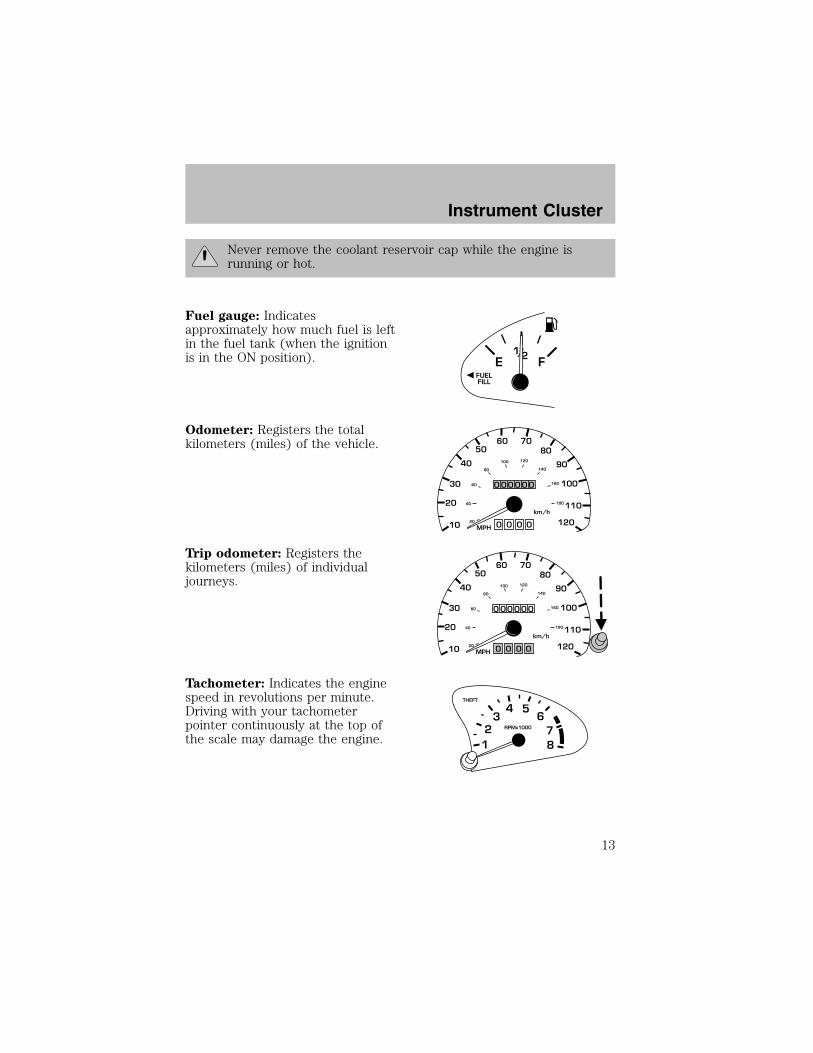
Never remove the coolant reservoir cap while the engine isrunning or hot.
Fuel gauge: Indicatesapproximately how much fuel is leftin the fuel tank (when the ignitionis in the ON position).
Odometer: Registers the totalkilometers (miles) of the vehicle.
Trip odometer: Registers thekilometers (miles) of individualjourneys.
Tachometer: Indicates the enginespeed in revolutions per minute.Driving with your tachometerpointer continuously at the top ofthe scale may damage the engine.
Instrument Cluster
13
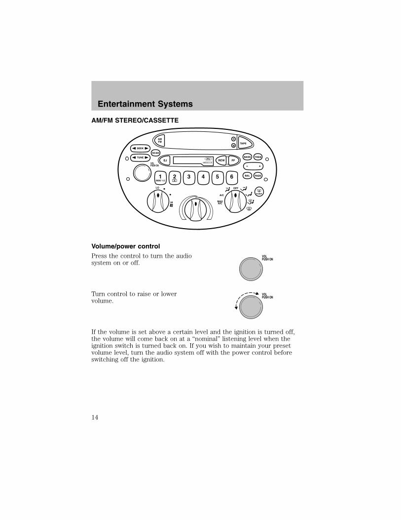
AM/FM STEREO/CASSETTE
Volume/power controlPress the control to turn the audiosystem on or off.
Turn control to raise or lowervolume.
If the volume is set above a certain level and the ignition is turned off,the volume will come back on at a “nominal” listening level when theignition switch is turned back on. If you wish to maintain your presetvolume level, turn the audio system off with the power control beforeswitching off the ignition.
OFF
R.DEFA/C
MAXA/CHI
LO
TUNE
SEEK
SCAN
AMFM
1SIDE 1-2
2 3 4 5 6
EJ REW FF
TAPE
H
M
+
BAL FADE
BASS TREB
DOLBY B NRVOLPUSH ON
VOLPUSH ON
VOLPUSH ON
Entertainment Systems
14

Bass/treble adjust• The bass adjust control allowsyou to increase or decrease theaudio system’s bass output.
• The treble adjust control allowsyou to increase or decrease theaudio system’s treble output.
Speaker balance/fade adjust• Speaker sound distribution can beadjusted between the right andleft speakers.
• Press the BAL control. Togglebetween the + and — control toadjust the speaker sound.
• Speaker sound can be adjusted between the front and rear speakers.• Press the FADE control. Toggle between the + and — control toadjust the speaker sound.
Seek functionThe seek function control works inradio or tape mode.
Seek function in radio mode• Press to find the next listenable station down the frequency band.• Press to find the next listenable station up the frequency band.
Seek function in tape mode• Press to listen to the previous selection on the tape.• Press to listen to the next selection on the tape.
Scan functionThe scan function works in radio ortape mode.
Scan function in radio modePress the SCAN control to hear a brief sampling of all listenable stationson the frequency band. Press the control again to stop the scan mode.
Entertainment Systems
15
Scan function in tape mode
Press the SCAN control to hear a short sampling of all selections on thetape. (The tape scans in a forward direction. At the end of the tape’sfirst side, direction automatically reverses to the opposite side of thetape.) To stop on a particular selection, press the control again.
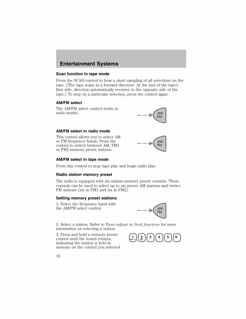
AM/FM selectThe AM/FM select control works inradio modes.
AM/FM select in radio modeThis control allows you to select AMor FM frequency bands. Press thecontrol to switch between AM, FM1or FM2 memory preset stations.
AM/FM select in tape mode
Press this control to stop tape play and begin radio play.
Radio station memory preset
The radio is equipped with six station memory preset controls. Thesecontrols can be used to select up to six preset AM stations and twelveFM stations (six in FM1 and six in FM2).
Setting memory preset stations1. Select the frequency band withthe AM/FM select control.
2. Select a station. Refer to Tune adjust or Seek function for moreinformation on selecting a station.
3. Press and hold a memory presetcontrol until the sound returns,indicating the station is held inmemory on the control you selected.
AMFM
AMFM
AMFM
1SIDE 1-2
2 3 4 5 6
Entertainment Systems
16

Setting the clockTo set the hour, press the hour (H)control and press :
• (+) to increase hour and
• (−) to decrease hour
To set the minute, press the minute(M) control and press:
• (+) to increase minutes and
• (−) to decrease minutes.
Tune adjustThe tune control works in radiomode.
Tune adjust in radio mode
• Press the to move to the nextfrequency down the band(whether or not a listenablestation is located there). Holdthe to move through the frequencies quickly.
• Press the to move to the next frequency up the band (whether ornot a listenable station is located there). Hold for quickmovement.
+
H
M
12:
+
H
M
:01
Entertainment Systems
17

Inserting a tapePush only slightly when inserting acassette tape (with the open edgeto the right). A cassette deckloading mechanism pulls the tape inthe rest of the way.
You can switch from radio to tape play by inserting a tape into thecassette deck.
Tape play select
Insert a tape to begin tape play.
Push only slightly when inserting a cassette tape (with the open edge tothe right). A cassette deck loading mechanism pulls the tape in the restof the way.
RewindThe rewind control works in tapemode.
• In tape mode, radio play willcontinue until rewind is stopped (with the TAPE control) or thebeginning of the tape is reached.
Fast forwardThe fast forward control works intape mode.
• In the tape mode, tape directionwill automatically reverse when the end of the tape is reached.
Tape side selectPress this control to play thealternate side of a tape.
Eject functionPress the control to stop and eject atape.
EJ REW FFDOLBY B NR
EJ
Entertainment Systems
18

Dolby� noise reductionDolby� noise reduction operatesonly in tape mode. Dolby� noisereduction reduces the amount ofhiss and static during tape playback.
Press the control to activate (and deactivate) Dolby� noise reduction.
Dolby� noise reduction manufactured under license from Dolby�Laboratories Licensing Corporation. “Dolby�” and the double-D symbolare registered trademarks of Dolby� Laboratories Licensing Corporation.
AM/FM RADIO WITH COMPACT DISC PLAYER
Volume/power controlEnsure that the ignition switch is inthe ACC or ON position.
Press the control to turn the audiosystem on. Turn the control to raiseor lower the volume.
Press the control again to turn theaudio system off.
NOTE: To prevent the battery from being discharged, do not leave theaudio system on for a long period when the engine is not running.
AM/FM selectThe AM/FM control works in radiomode.
CLOCK
PUSHPOWER-VOL
AUDIO DISC1
RDM2
RPT SCAN AUTOM
AMFM
CDH
M
TUNESEEK
TRACK3 4 5
DISC IN
PUSHPOWER-VOL
AMFM
Entertainment Systems
19
AM/FM select in radio mode
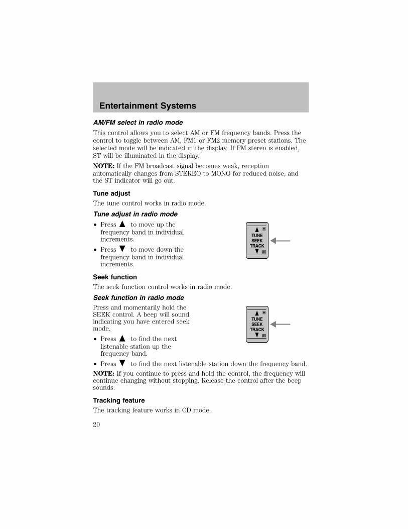
This control allows you to select AM or FM frequency bands. Press thecontrol to toggle between AM, FM1 or FM2 memory preset stations. Theselected mode will be indicated in the display. If FM stereo is enabled,ST will be illuminated in the display.
NOTE: If the FM broadcast signal becomes weak, receptionautomatically changes from STEREO to MONO for reduced noise, andthe ST indicator will go out.
Tune adjustThe tune control works in radio mode.
Tune adjust in radio mode
• Press to move up thefrequency band in individualincrements.
• Press to move down thefrequency band in individualincrements.
Seek functionThe seek function control works in radio mode.
Seek function in radio modePress and momentarily hold theSEEK control. A beep will soundindicating you have entered seekmode.
• Press to find the nextlistenable station up thefrequency band.
• Press to find the next listenable station down the frequency band.
NOTE: If you continue to press and hold the control, the frequency willcontinue changing without stopping. Release the control after the beepsounds.
Tracking featureThe tracking feature works in CD mode.
H
M
TUNESEEK
TRACK
H
M
TUNESEEK
TRACK
Entertainment Systems
20
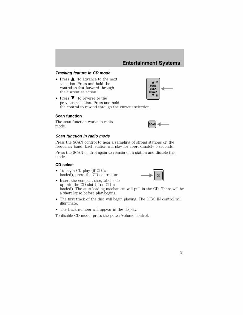
Tracking feature in CD mode
• Press to advance to the nextselection. Press and hold thecontrol to fast forward throughthe current selection.
• Press to reverse to theprevious selection. Press and holdthe control to rewind through the current selection.
Scan functionThe scan function works in radiomode.
Scan function in radio mode
Press the SCAN control to hear a sampling of strong stations on thefrequency band. Each station will play for approximately 5 seconds.
Press the SCAN control again to remain on a station and disable thismode.
CD select• To begin CD play (if CD isloaded), press the CD control, or
• Insert the compact disc, label sideup into the CD slot (if no CD isloaded). The auto loading mechanism will pull in the CD. There will bea short lapse before play begins.
• The first track of the disc will begin playing. The DISC IN control willilluminate.
• The track number will appear in the display.
To disable CD mode, press the power/volume control.
H
M
TUNESEEK
TRACK
SCAN
CD
Entertainment Systems
21
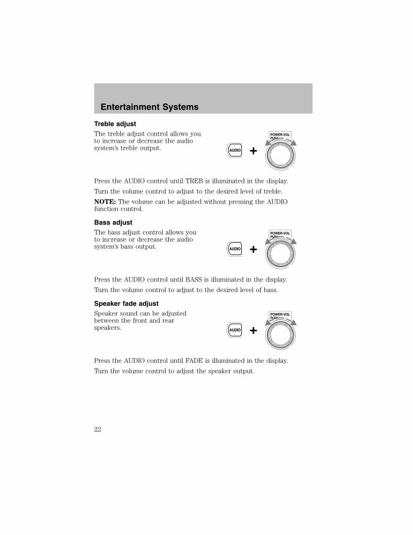
Treble adjustThe treble adjust control allows youto increase or decrease the audiosystem’s treble output.
Press the AUDIO control until TREB is illuminated in the display.
Turn the volume control to adjust to the desired level of treble.
NOTE: The volume can be adjusted without pressing the AUDIOfunction control.
Bass adjustThe bass adjust control allows youto increase or decrease the audiosystem’s bass output.
Press the AUDIO control until BASS is illuminated in the display.
Turn the volume control to adjust to the desired level of bass.
Speaker fade adjustSpeaker sound can be adjustedbetween the front and rearspeakers.
Press the AUDIO control until FADE is illuminated in the display.
Turn the volume control to adjust the speaker output.
PUSHPOWER-VOL
+AUDIO
PUSHPOWER-VOL
+AUDIO
PUSHPOWER-VOL
+AUDIO
Entertainment Systems
22

Speaker balance adjustSpeaker sound distribution can beadjusted between the right and leftspeakers.
Press the AUDIO control until BAL is illuminated in the display.
Turn the volume control to adjust the speakers.
NOTE: Approximately 5 seconds after selecting any AUDIO mode(treble, bass, fade, balance or volume), the system will automaticallydefault to the volume function. To reset these modes, press andmomentarily hold the AUDIO control. The unit will beep and CL willappear in the display.
Radio station memory preset
The radio is equipped with five station memory preset controls. Thesecontrols can be used to select up to five preset AM stations and ten FMstations (five in FM1 and five in FM2).
Setting memory preset stations
1. Select the frequency band with the AM/FM control.
2. Select the desired station.
3. Press and momentarily hold the desired preset control until a beep isheard.
The preset control number will illuminate in the display. This indicatesthe station is held in memory on the control you selected. Repeat thisprocedure to store other stations in memory.
Auto memory tuning
Auto memory tuning allows you to set strong radio stations withoutlosing your original manually set preset stations. This is especially usefulwhen you are in an area where the local stations are not known.
PUSHPOWER-VOL
+AUDIO
Entertainment Systems
23

Starting auto memory tuning1. Select a frequency using the AM/FM control.
2. Press and momentarily hold theAUTO M (auto memory) control.
3. The audio system will select thefive strongest stations on the frequency band. When the stations arefilled, the station stored in memory preset control 1 will start playing.
Press the AUTO M control to recall stations in the auto memory. Onestation will be selected each time you press the AUTO M control and theauto memory number will be displayed.
NOTE: If the power supply is interrupted (the fuse blows or the batteryis disconnected), the preset channels will be canceled.
Random playThe random play feature works inCD mode and plays the selectionson the current CD in random order.
Random play in CD modePress the RDM control during play. RDM will illuminate in the display.
The next selection will be randomly selected.
To disengage random play, press the RDM control again.
Repeat playThe repeat play feature works in CDmode and repeats the current CDselection.
Repeat play in CD modePress the RPT control during play. RPT will illuminate in the display.
The current selection will be repeated.
To disengage repeat play, press the RPT control again.
AUTOM
RDM2
RPT3
Entertainment Systems
24
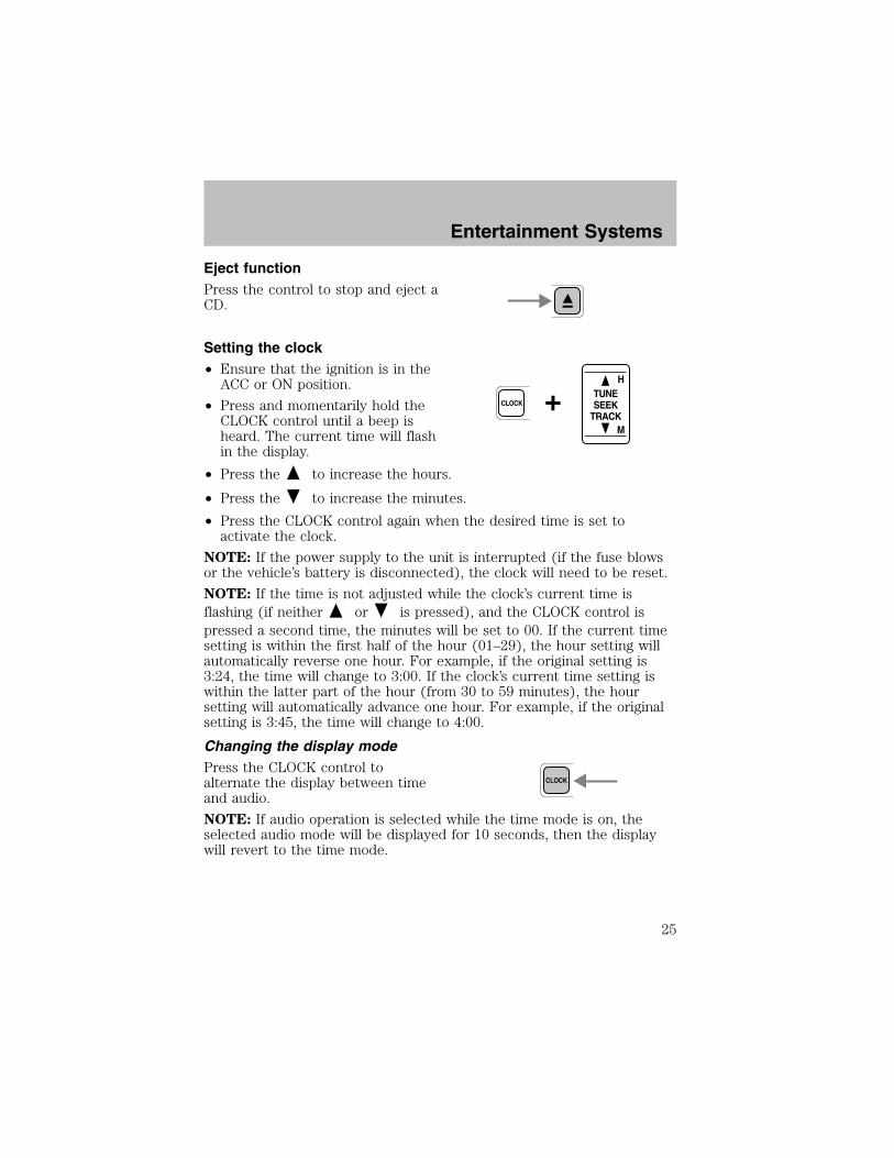
Eject functionPress the control to stop and eject aCD.
Setting the clock• Ensure that the ignition is in theACC or ON position.
• Press and momentarily hold theCLOCK control until a beep isheard. The current time will flashin the display.
• Press the to increase the hours.
• Press the to increase the minutes.
• Press the CLOCK control again when the desired time is set toactivate the clock.
NOTE: If the power supply to the unit is interrupted (if the fuse blowsor the vehicle’s battery is disconnected), the clock will need to be reset.
NOTE: If the time is not adjusted while the clock’s current time isflashing (if neither or is pressed), and the CLOCK control ispressed a second time, the minutes will be set to 00. If the current timesetting is within the first half of the hour (01–29), the hour setting willautomatically reverse one hour. For example, if the original setting is3:24, the time will change to 3:00. If the clock’s current time setting iswithin the latter part of the hour (from 30 to 59 minutes), the hoursetting will automatically advance one hour. For example, if the originalsetting is 3:45, the time will change to 4:00.
Changing the display modePress the CLOCK control toalternate the display between timeand audio.
NOTE: If audio operation is selected while the time mode is on, theselected audio mode will be displayed for 10 seconds, then the displaywill revert to the time mode.
+CLOCK
H
M
TUNESEEK
TRACK
CLOCK
Entertainment Systems
25

RADIO FREQUENCIESAM and FM frequencies are established by the Federal CommunicationsCommission (FCC) and the Canadian Radio and TelecommunicationsCommission (CRTC). Those frequencies are:
AM - 530, 540–1700, 1710 kHz
FM- 87.7, 87.9–107.7, 107.9 MHz
RADIO RECEPTION FACTORSThere are three factors that can effect radio reception:
• Distance/strength: The further you travel from an FM station, theweaker the signal and the weaker the reception.
• Terrain: Hills, mountains, tall buildings, power lines, electric fences,traffic lights and thunderstorms can interfere with your reception.
• Station overload: When you pass a broadcast tower, a stronger signalmay overtake a weaker one and play while the weak station frequencyis displayed.
CASSETTE/PLAYER CAREDo:
• Use only cassettes that are 90 minutes long or less.
• Tighten very loose tapes by inserting a finger or pencil into the holeand turning the hub.
• Remove loose labels before inserting tapes.
• Allow tapes which have been subjected to extreme heat, humidity orcold to reach a moderate temperature before playing.
• Clean the cassette player head with a cassette cleaning cartridge after10–12 hours of play to maintain good sound/operation.
Don’t:
• Expose tapes to direct sunlight, extreme humidity, heat or cold.
• Leave tapes in the cassette player for a long time when not beingplayed.
Entertainment Systems
26
CD/CD PLAYER CAREDo:
• Handle discs by their edges only. Never touch the playing surface.
• Inspect discs before playing. Clean only with an approved CD cleanerand wipe from the center out.
Don’t:
• Expose discs to direct sunlight or heat sources for extended periodsof time.
• Insert more than one disc into each slot of the CD changer magazine.
• Clean using a circular motion.
CD units are designed to play commercially pressed 12 cm (4.75in) audio compact discs only. Due to technical incompatibility,certain recordable and re-recordable compact discs may notfunction correctly when used in Ford CD players. Irregularshaped CDs, CDs with a scratch protection film attached, and CDswith homemade paper (adhesive) labels should not be insertedinto the CD player. The label may peel and cause the CD tobecome jammed. It is recommended that homemade CDs beidentified with permanent felt tip marker rather than adhesivelabels. Ball point pens may damage CDs. Please contact yourdealer for further information.
AUDIO SYSTEM WARRANTY AND SERVICERefer to the Warranty Guide for audio system warranty information. Ifservice is necessary, see your dealer or qualified technician.
Entertainment Systems
27
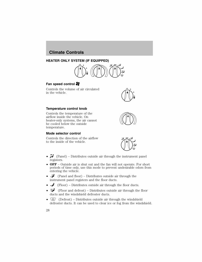
HEATER ONLY SYSTEM (IF EQUIPPED)
Fan speed control
Controls the volume of air circulatedin the vehicle.
Temperature control knobControls the temperature of theairflow inside the vehicle. Onheater-only systems, the air cannotbe cooled below the outsidetemperature.
Mode selector controlControls the direction of the airflowto the inside of the vehicle.
• (Panel) – Distributes outside air through the instrument panelregisters.
• OFF – Outside air is shut out and the fan will not operate. For shortperiods of time only, use this mode to prevent undesirable odors fromentering the vehicle.
• (Panel and floor) – Distributes outside air through theinstrument panel registers and the floor ducts.
• (Floor) – Distributes outside air through the floor ducts.
• (Floor and defrost) – Distributes outside air through the floorducts and the windshield defroster ducts.
• (Defrost) – Distributes outside air through the windshielddefroster ducts. It can be used to clear ice or fog from the windshield.
OFF
HI
LO
HI
LO
OFF
Climate Controls
28
Operating tips
• In humid weather, place the climate control system in Defrost ( )before driving. This will reduce fogging on your windshield. Once thewindshield has been cleared, select any desired position.
• To reduce humidity buildup inside the vehicle, do not drive with theclimate control system in the OFF position.
• Under normal weather conditions, your vehicle’s climate controlsystem should be left in any position other than OFF position whenthe vehicle is parked. This allows the vehicle to “breathe” through theoutside air inlet duct.
• Under snowy or dirty weather conditions, your vehicle’s climatecontrol system should be left in the OFF position when the vehicle isparked. This allows the climate control system to be free fromcontamination of outside pollutants.
• Do not place objects under the front seat which may interfere withthe airflow to the rear seats (if equipped).
• Remove any snow, ice, or leaves from the air intake area (at the baseof the windshield and underneath the hood).
• Do not place objects over the defroster outlets. These objects mayblock airflow and reduce your visibility through the windshield. Avoidplacing small objects on top of the instrument panel. These objectscan fall into the defroster outlets and block airflow, in addition to,damaging your climate control system.
Do not place objects on top of the instrument panel, as theseobjects may become projectiles in a collision or sudden stop.
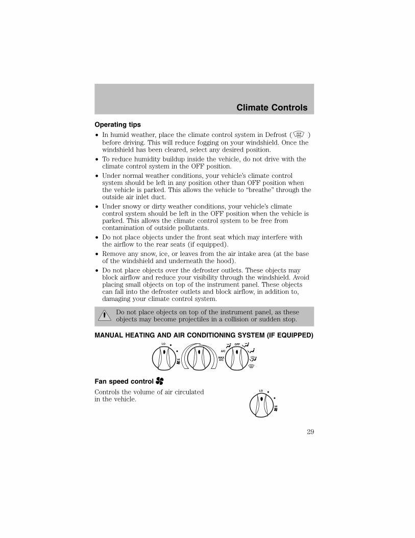
MANUAL HEATING AND AIR CONDITIONING SYSTEM (IF EQUIPPED)
Fan speed control
Controls the volume of air circulatedin the vehicle.
HI
LO OFF
A/C
MAXA/C
HI
LO
Climate Controls
29

Temperature control knobControls the temperature of theairflow inside the vehicle.
Mode Selector ControlControls the direction of the airflowto the inside of the vehicle.
The air conditioning compressor can operate in all modes exceptand . However, the air conditioning will only function if the outsidetemperature is about 6°C (43°F) or higher.
Since the air conditioner removes considerable moisture from the airduring operation, it is normal if clear water drips on the ground underthe air conditioner drain while the system is working and even after youhave stopped the vehicle.
• MAX A/C – Uses recirculated air to cool the vehicle. MAX A/C is noisierthan A/C but more economical and will cool the inside of the vehiclefaster. Airflow will be from the instrument panel registers. This modecan also be used to prevent undesirable odors from entering the vehicle.
• A/C – Uses outside air to cool the vehicle. It is quieter than MAX A/C butnot as economical. Airflow will be from the instrument panel registers.
• (Panel) – Distributes outside air through the instrument panelregisters. However, the air will not be cooled below the outsidetemperature because the air conditioning does not operate in this mode.
• OFF – Outside air is shut out and the fan will not operate. For shortperiods of time only, use this mode to prevent undesirable odors fromentering the vehicle.
• (Panel and floor) – Distributes outside air through theinstrument panel registers and the floor ducts. Heating and airconditioning capabilities are provided in this mode. For addedcustomer comfort, when the temperature control knob is anywhere inbetween the full hot and full cold positions, the air distributed throughthe floor ducts will be slightly warmer than the air sent to theinstrument panel registers.
OFF
A/C
MAXA/C
Climate Controls
30
• (Floor) – Distributes outside air through the floor ducts.However, the air will not be cooled below the outside temperaturebecause the air conditioning does not operate in this mode.
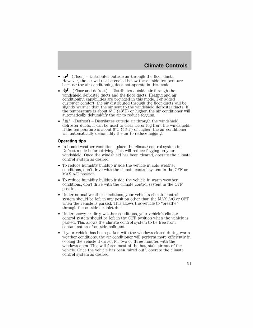
• (Floor and defrost) – Distributes outside air through thewindshield defroster ducts and the floor ducts. Heating and airconditioning capabilities are provided in this mode. For addedcustomer comfort, the air distributed through the floor ducts will beslightly warmer than the air sent to the windshield defroster ducts. Ifthe temperature is about 6°C (43°F) or higher, the air conditioner willautomatically dehumidify the air to reduce fogging.
• (Defrost) – Distributes outside air through the windshielddefroster ducts. It can be used to clear ice or fog from the windshield.If the temperature is about 6°C (43°F) or higher, the air conditionerwill automatically dehumidify the air to reduce fogging.
Operating tips• In humid weather conditions, place the climate control system inDefrost mode before driving. This will reduce fogging on yourwindshield. Once the windshield has been cleared, operate the climatecontrol system as desired.
• To reduce humidity buildup inside the vehicle in cold weatherconditions, don’t drive with the climate control system in the OFF orMAX A/C position.
• To reduce humidity buildup inside the vehicle in warm weatherconditions, don’t drive with the climate control system in the OFFposition.
• Under normal weather conditions, your vehicle’s climate controlsystem should be left in any position other than the MAX A/C or OFFwhen the vehicle is parked. This allows the vehicle to “breathe”through the outside air inlet duct.
• Under snowy or dirty weather conditions, your vehicle’s climatecontrol system should be left in the OFF position when the vehicle isparked. This allows the climate control system to be free fromcontamination of outside pollutants.
• If your vehicle has been parked with the windows closed during warmweather conditions, the air conditioner will perform more efficiently incooling the vehicle if driven for two or three minutes with thewindows open. This will force most of the hot, stale air out of thevehicle. Once the vehicle has been “aired out”, operate the climatecontrol system as desired.
Climate Controls
31

• Do not put objects under the front seat which may interfere with theairflow to the rear seats.
• Remove any snow, ice or leaves from the air intake area (at thebottom of the windshield and underneath the hood).
• Do not place objects over the defroster outlets. These objects canblock airflow and reduce visibility through your windshield. Avoidplacing small objects on top of the instrument panel. These objectsmay fall down into the defroster outlets and block airflow, in additionto, damaging the climate control system.
To aid in side window defogging/demisting in cold weather conditions:
1. Select the position that distributes air through the Panel and Floor.
2. Set the temperature control to full heat.
3. Set the fan speed to full fan.
4. Direct the outer panel vents towards the side windows.
5. To increase airflow to the outer panel vents, close the central panelvents.
Do not place objects on top of the instrument panel as theseobjects may become projectiles in a collision or sudden stop.
REAR WINDOW DEFROSTER
Clears the rear window of thin ice and fog. To operate:
1. Turn the ignition to the ON position.
2. Press and release the controlonce to turn on. The light will be litwhile the rear window defroster ison.
3. Press and release the controlagain to turn off.
The defroster will automatically turn off after 15 minutes.
R.DEF
Climate Controls
32
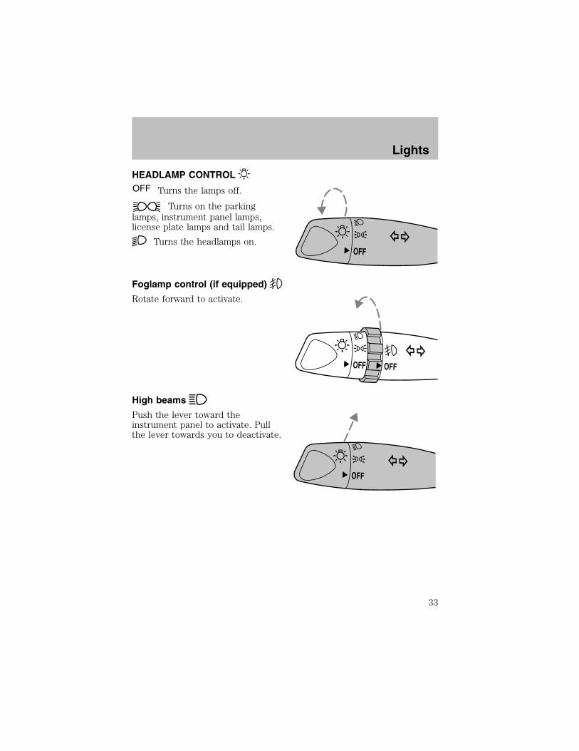
HEADLAMP CONTROL
Turns the lamps off.
Turns on the parkinglamps, instrument panel lamps,license plate lamps and tail lamps.
Turns the headlamps on.
Foglamp control (if equipped)
Rotate forward to activate.
High beams
Push the lever toward theinstrument panel to activate. Pullthe lever towards you to deactivate.
OFF
OFF OFF
OFF
Lights
33

Flash to passPull toward you slightly to activateand release to deactivate.
PANEL DIMMER CONTROLUse to adjust the brightness of the instrument panel during headlampand parklamp operation.
• Rotate up to brighten.
• Rotate down to dim.
The dome lamp will not illuminate if the control switch is in the OFFposition.
AIMING THE HEADLAMPSYour vehicle is equipped with a Vehicle Headlamp Aim Device (VHAD)on each headlamp. Each headlamp may be properly aimed in the vertical(up/down) and the horizontal (left/right) directions using your VHADsystem. The headlamps on your vehicle are properly aimed at theassembly plant.A bubble (vertical indicator) that is not centered between the two redlines does not necessarily indicate out-of-aim headlamps. If your vehicleis not positioned on a level surface, the slope will be included in thevertical indication. Therefore, vertical and horizontal headlampadjustment should be performed only when the beam direction appearsto be incorrect.
You will need one 4 mm wrench or socket to make the adjustments.
OFF
Lights
34
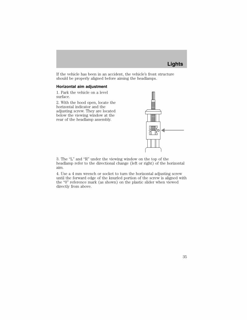
If the vehicle has been in an accident, the vehicle’s front structureshould be properly aligned before aiming the headlamps.
Horizontal aim adjustment1. Park the vehicle on a levelsurface.
2. With the hood open, locate thehorizontal indicator and theadjusting screw. They are locatedbelow the viewing window at therear of the headlamp assembly.
3. The “L” and “R” under the viewing window on the top of theheadlamp refer to the directional change (left or right) of the horizontalaim.
4. Use a 4 mm wrench or socket to turn the horizontal adjusting screwuntil the forward edge of the knurled portion of the screw is aligned withthe “0” reference mark (as shown) on the plastic slider when vieweddirectly from above.
Lights
35

Vertical aim adjustment1. Park the vehicle on a levelsurface.
2. With the hood open, locate thebubble level and the verticaladjustment screw. The adjustmentscrew is located on the outboardside of the headlamp below theheadlamp upper attachment.
3. The “UP” and “DN” on the bubbleindicate the directional change (upor down) of the vertical aim.
4. Use a 4 mm wrench or socket toturn the vertical adjusting screwclockwise or counterclockwise untilthe bubble is centered between thelines.
Repeat the above process to the other headlamp, if necessary.
TURN SIGNAL CONTROL
• Push down to activate the leftturn signal.
• Push up to activate the right turnsignal.
L
R
UP
DN
DN
UP
OFF
Lights
36

INTERIOR LAMPS
Dome lamp and map lamps (if equipped)The dome lamp is located overheadbetween the driver and passengerseats.
The dome lamp will stay on if thecontrol is moved to the ON position.When the control is moved to theDOOR position, the lamp will onlycome on if a door is opened. If thecontrol is moved to the OFFposition, the lamp will not come onat all.
The map lamps and controls arelocated on the dome lamp. Press thecontrols on either side of each maplamp to activate the lamps.
Map lamps (if equipped)The map lamps and controls are located on the dome lamp. Press thecontrols on either side of the dome lamp to activate the map lamps.
If equipped with a moon roof, themap lamps are located on the moonroof control panel. Press the controlnext to the map lamp to illuminatethe lamp.
BULBS
Replacing exterior bulbsCheck the operation of all the bulbs frequently.
Using the right bulbsReplacement bulbs are specified in the chart below. Headlamp bulbsmust be marked with an authorized “D.O.T.” for North America and an“E” for Europe to assure lamp performance, light brightness, lightpattern and safe visibility. The correct bulbs will not damage the lampassembly or void the lamp assembly warranty and will provide qualitybulb burn time.
OFF DOOR ON
OPEN
Lights
37

Function Trade Number
Front park/turn lamps 3157KFoglamps (if equipped) 881Headlamps-aero high and low beam 9007Rear license plate lamps 168High-mount brake lamp 921Backup lamps 3156KBrake lamps 3157KInterior overhead lamp 12V/10WAll replacement bulbs are clear in color except where noted.To replace all instrument panel lights - see your dealer
INTERIOR BULBS
Dome lamp1. Remove the lamp lens by applyingpressure to both tabs at the top ofthe lamp and pulling lensdownward.
2. Pull out the burned-out bulb andinstall a new one.
3. Install the lamp lens by applyingpressure to both sides of the lamplens and popping the lamp lens upon the assembly.
Map lamps
For bulb replacement, see a qualified service technician or your dealer.
Replacing headlamp bulbs
1. Make sure the headlamp switch is in the OFF position..
2. Open the hood and disconnect the headlamp wiring socket from thein-line connector. This will make it easier to change the bulb.
OFF DOOR ON
Lights
38
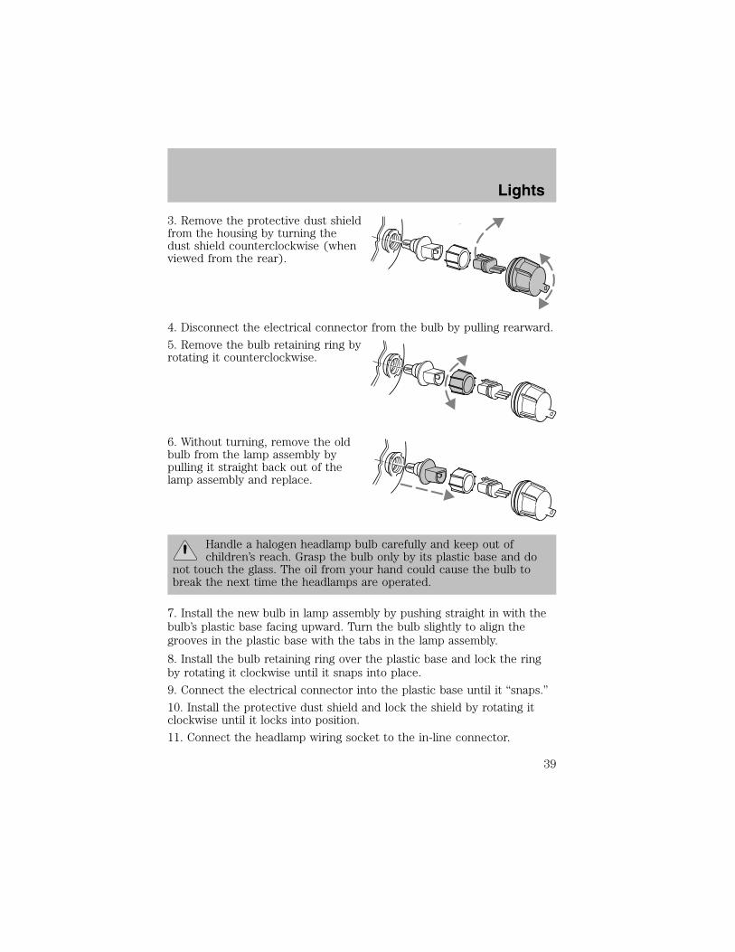
3. Remove the protective dust shieldfrom the housing by turning thedust shield counterclockwise (whenviewed from the rear).
4. Disconnect the electrical connector from the bulb by pulling rearward.
5. Remove the bulb retaining ring byrotating it counterclockwise.
6. Without turning, remove the oldbulb from the lamp assembly bypulling it straight back out of thelamp assembly and replace.
Handle a halogen headlamp bulb carefully and keep out ofchildren’s reach. Grasp the bulb only by its plastic base and do
not touch the glass. The oil from your hand could cause the bulb tobreak the next time the headlamps are operated.
7. Install the new bulb in lamp assembly by pushing straight in with thebulb’s plastic base facing upward. Turn the bulb slightly to align thegrooves in the plastic base with the tabs in the lamp assembly.
8. Install the bulb retaining ring over the plastic base and lock the ringby rotating it clockwise until it snaps into place.
9. Connect the electrical connector into the plastic base until it “snaps.”
10. Install the protective dust shield and lock the shield by rotating itclockwise until it locks into position.
11. Connect the headlamp wiring socket to the in-line connector.
Lights
39
12. Turn the headlamps on and make sure they work properly. If theheadlamp was correctly aligned before you changed the bulb, you shouldnot need to align it again.
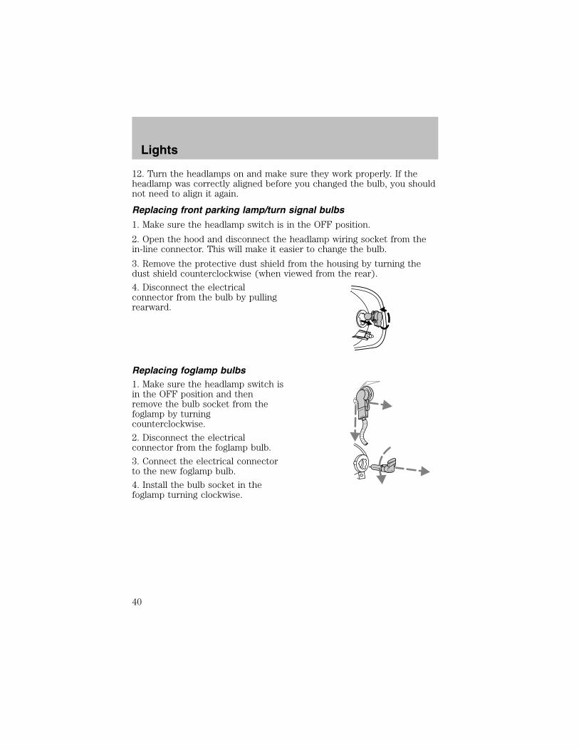
Replacing front parking lamp/turn signal bulbs
1. Make sure the headlamp switch is in the OFF position.
2. Open the hood and disconnect the headlamp wiring socket from thein-line connector. This will make it easier to change the bulb.
3. Remove the protective dust shield from the housing by turning thedust shield counterclockwise (when viewed from the rear).
4. Disconnect the electricalconnector from the bulb by pullingrearward.
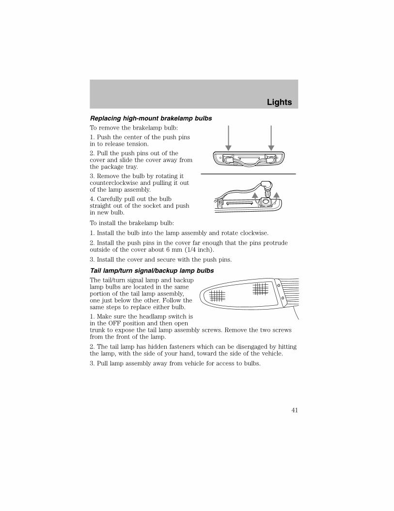
Replacing foglamp bulbs1. Make sure the headlamp switch isin the OFF position and thenremove the bulb socket from thefoglamp by turningcounterclockwise.
2. Disconnect the electricalconnector from the foglamp bulb.
3. Connect the electrical connectorto the new foglamp bulb.
4. Install the bulb socket in thefoglamp turning clockwise.
Lights
40
Replacing high-mount brakelamp bulbsTo remove the brakelamp bulb:
1. Push the center of the push pinsin to release tension.
2. Pull the push pins out of thecover and slide the cover away fromthe package tray.
3. Remove the bulb by rotating itcounterclockwise and pulling it outof the lamp assembly.
4. Carefully pull out the bulbstraight out of the socket and pushin new bulb.
To install the brakelamp bulb:
1. Install the bulb into the lamp assembly and rotate clockwise.
2. Install the push pins in the cover far enough that the pins protrudeoutside of the cover about 6 mm (1/4 inch).
3. Install the cover and secure with the push pins.
Tail lamp/turn signal/backup lamp bulbsThe tail/turn signal lamp and backuplamp bulbs are located in the sameportion of the tail lamp assembly,one just below the other. Follow thesame steps to replace either bulb.
1. Make sure the headlamp switch isin the OFF position and then opentrunk to expose the tail lamp assembly screws. Remove the two screwsfrom the front of the lamp.
2. The tail lamp has hidden fasteners which can be disengaged by hittingthe lamp, with the side of your hand, toward the side of the vehicle.
3. Pull lamp assembly away from vehicle for access to bulbs.
Lights
41

4. Remove the bulb socket byrotating it counterclockwise, thenpulling it out of the lamp assembly.
5. Pull the bulb from the socket andpush in the new bulb.
6. Install the bulb socket into thelamp by rotating it clockwise.
7. Position the tail lamp on thevehicle and gently tap the lens toengage the clips. Install the screws.
License plate lampsTo change the license plate bulbs:
1. Remove two screws and thelicense plate lamp assembly fromthe rear bumper.
2. Carefully pull the bulb out fromthe lamp assembly and push in thenew bulb.
3. Install the lamp assembly on rearbumper with two screws.
Lights
42

MULTI-FUNCTION LEVER
Windshield wiper:
• For intermittent wiping, move thecontrol down one position androtate the wiper switch to thedesired position.
• For low speed wiping, move thecontrol down two positions.
• For high speed wiping, move thecontrol down three positions.
Windshield washer:
• For mist wiping, move the controlup one position.
• To spray the washer fluid, pullthe wiper control toward you.
MISTOFF
INT1 2
F
S
PULL INT
MISTOFF
INT1 2
F
S
PULL INT
Driver Controls
43

Changing the wiper blades1. Pull the wiper arm away from thevehicle. Turn the blade at an anglefrom the wiper arm. Push the lockpin manually to release the bladeand pull the wiper blade downtoward the windshield to remove itfrom the arm.
2. Attach the new wiper to thewiper arm and press it into placeuntil a click is heard.
3. Replace wiper blades every 6months for optimum performance.
TILT STEERING (IF EQUIPPED)Pull the tilt steering control down tomove the steering wheel up ordown. Hold the control whileadjusting the wheel to the desiredposition, then push the control backup to lock the steering wheel inposition.
Never adjust the steeringwheel when the vehicle is
moving.
POWER WINDOWS (IF EQUIPPED)
When closing the powerwindows, you should verify
they are free of obstructions andensure that children and/or petsare not in the proximity of thewindow openings.
Driver Controls
44
Press and hold the bottom part of the rocker switch to open the window.Press and hold the top part of the rocker switch to close the window.
One touch downAllows the driver’s window to openfully without holding the controldown. Press completely down onthe bottom part of the rocker switchand release quickly. Press again tostop.
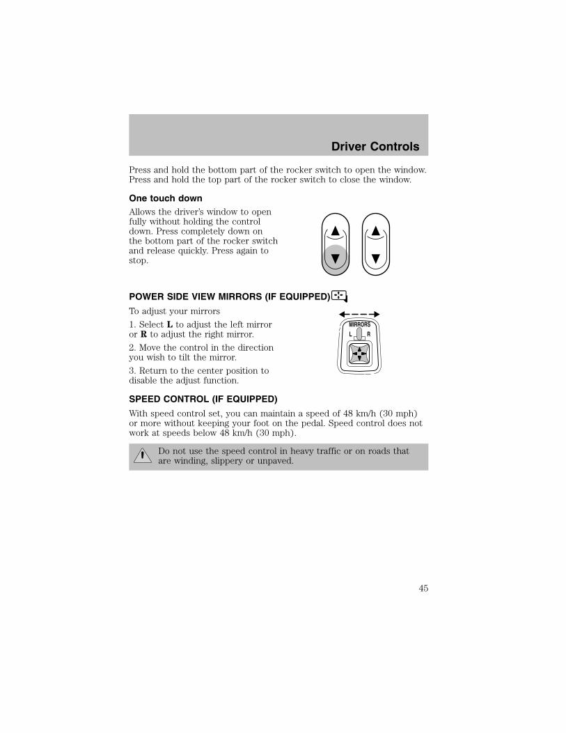
POWER SIDE VIEW MIRRORS (IF EQUIPPED)
To adjust your mirrors
1. Select L to adjust the left mirroror R to adjust the right mirror.
2. Move the control in the directionyou wish to tilt the mirror.
3. Return to the center position todisable the adjust function.
SPEED CONTROL (IF EQUIPPED)
With speed control set, you can maintain a speed of 48 km/h (30 mph)or more without keeping your foot on the pedal. Speed control does notwork at speeds below 48 km/h (30 mph).
Do not use the speed control in heavy traffic or on roads thatare winding, slippery or unpaved.
Driver Controls
45
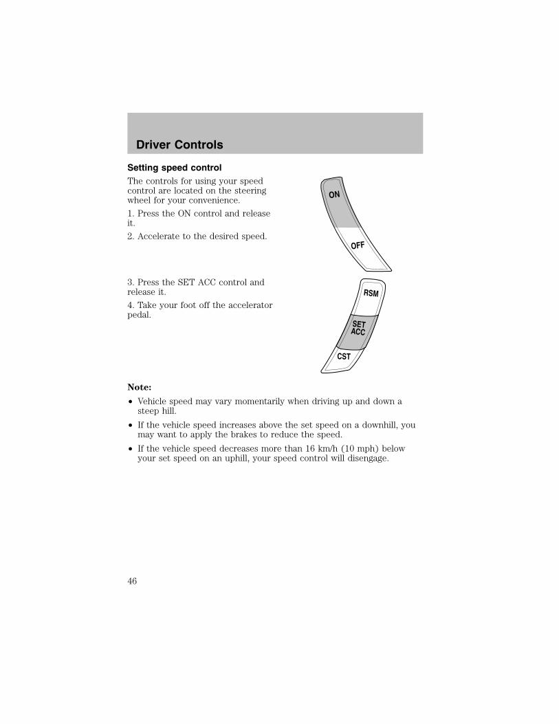
Setting speed controlThe controls for using your speedcontrol are located on the steeringwheel for your convenience.
1. Press the ON control and releaseit.
2. Accelerate to the desired speed.
3. Press the SET ACC control andrelease it.
4. Take your foot off the acceleratorpedal.
Note:
• Vehicle speed may vary momentarily when driving up and down asteep hill.
• If the vehicle speed increases above the set speed on a downhill, youmay want to apply the brakes to reduce the speed.
• If the vehicle speed decreases more than 16 km/h (10 mph) belowyour set speed on an uphill, your speed control will disengage.
ON
OFF
RSM
CST
SETACC
Driver Controls
46
Resuming a set speedPress the RSM (resume) control andrelease it. This will automaticallyreturn the vehicle to the previouslyset speed. The RSM control will notwork if the vehicle speed is notfaster than 48 km/h (30 mph).
Increasing speed while using speed controlThere are two ways to set a higherspeed:
• Press and hold the SET ACCcontrol until you get to thedesired speed, then release thecontrol. You can also use the SETACCEL control to operate theTap-Up function. Press andrelease this control to increasethe vehicle set speed in smallamounts by 1.6 km/h (1 mph).
• Use the accelerator pedal to get to the desired speed. When thevehicle reaches that speed press and release the SET ACC control.
Reducing speed while using speed controlThere are two ways to reduce a setspeed:
• Press and hold the CST controluntil you get to the desiredspeed, then release the control.You can also use the CST controlto operate the Tap-Downfunction. Press and release thiscontrol to decrease the vehicleset speed in small amounts by 1.6km/h (1 mph).
RSM
CST
SETACC
RSM
CST
SETACC
RSM
CST
SETACC
Driver Controls
47

• Depress the brake pedal until thedesired vehicle speed is reached,press the SET ACC control.
Turning off speed control
There are two ways to turn off the speed control:
• Depress the brake pedal or the clutch pedal (if equipped). This willnot erase your vehicles previously set speed.
• Press the speed control OFFcontrol.
Note: When you turn off the speedcontrol or the ignition, your speedcontrol set speed memory is erased.
MOON ROOF (IF EQUIPPED)• Press and hold OPEN to raise themoon roof to the vent position.
• Press OPEN again to fully openthe moon roof.
• Press the opposite end of thetoggle control to close the moonroof from either position.
Sliding shade
The moon roof has a sliding shade that you can open or close when themoon roof is closed.
RSM
CST
SETACC
ON
OFF
OPEN
Driver Controls
48
CELL PHONE USE
The use of Mobile Communications Equipment has become increasinglyimportant in the conduct of business and personal affairs. However,drivers must not compromise their own or others’ safety when usingsuch equipment. Mobile Communications can enhance personal safetyand security when appropriately used, particularly in emergencysituations. Safety must be paramount when using mobile communicationsequipment to avoid negating these benefits.
Mobile Communication Equipment includes, but is not limited to cellularphones, pagers, portable email devices, in vehicle communicationssystems, telematics devices and portable two-way radios.
A driver’s first responsibility is the safe operation of the vehicle.The most important thing you can do to prevent a crash is to
avoid distractions and pay attention to the road. Wait until it is safe tooperate Mobile Communications Equipment.
INTERIOR TRUNK CONTROLPress the remote trunk releasecontrol on the instrument panel toopen the trunk.
TRU
NKRELEASE
TRU
NKRELEASE
Driver Controls
49
POSITIVE RETENTION FLOOR MATPosition the driver floor mat so thatthe eyelet is over the pointed end ofthe retention post and rotateforward to lock in. Make sure thatthe mat does not interfere with theoperation of the accelerator or thebrake pedal. To remove the floormat, reverse the installationprocedure.
Driver Controls
50

KEYS
The key operates all locks on your vehicle. In case of loss, replacementkeys are available from your dealer.
You should always carry a second key with you in a safe place in caseyou require it in an emergency.
POWER DOOR LOCKS (IF EQUIPPED)Press U to unlock all doors and L tolock all doors.
INTERIOR LUGGAGE COMPARTMENT RELEASE
Your vehicle is equipped with a mechanical interior luggage compartmentrelease handle that provides a means of escape for children and adults inthe event they become locked inside the luggage compartment.
Adults are advised to familiarize themselves with the operation andlocation of the release handle.
U L
Locks and Security
51

To open the luggage compartmentdoor (lid) from within the luggagecompartment, pull the illuminated“T” shaped handle and push up onthe trunk lid. The handle iscomposed of a material that willglow for hours in darkness followingbrief exposure to ambient light.
The “T” shaped handle will belocated either on the luggagecompartment door (lid) or insidethe luggage compartment near thetail lamps.
Keep vehicle doors andluggage compartment
locked and keep keys and remotetransmitters out of a child’s reach.Unsupervised children could lockthemselves in the trunk and riskinjury. Children should be taughtnot to play in vehicles.
On hot days, the temperature in the trunk or vehicle interior canrise very quickly. Exposure of people or animals to these high
temperatures for even a short time can cause death or seriousheat-related injuries, including brain damage. Small children areparticularly at risk.
REMOTE ENTRY SYSTEM (IF EQUIPPED)This device complies with part 15 of the FCC rules and with RS-210 ofIndustry Canada. Operation is subject to the following two conditions:(1) This device may not cause harmful interference, and (2) This devicemust accept any interference received, including interference that maycause undesired operation.
Locks and Security
52

Changes or modifications not expressly approved by the partyresponsible for compliance could void the user’s authority tooperate the equipment.
Your vehicle may have an all-door remote entry system or a driver’s dooronly remote entry system.
The all-door remote entry systemallows you to:
• lock or unlock all vehicle doorswithout a key.
• arm and disarm the anti-theftsystem. (For more information onthe anti-theft system, refer toAnti-theft system in thischapter.)
• open the trunk.• activate the panic alarm.The driver’s door only entry system allows you to:• lock the driver’s door• unlock the driver’s door only without a key.• activate the panic alarm.
• open the trunk
The remote entry features only operate with the ignition in the LOCKposition.
If there is any potential remote keyless entry problem with your vehicle,ensure ALL remote entry transmitters are brought to the dealership,to aid in troubleshooting.
Unlocking the doors
1. Press and release to unlock the driver’s door. Note: The interiorlamps will illuminate.
2. With the all-door remote entry, press and release again withinthree seconds to unlock all the doors.
The remote entry system activates the illuminated entry feature. Thisfeature turns on the interior lamps for 20 seconds or until the ignition isturned to the ON position. The dome lamp control must be set to theDOOR position in order for the illuminated entry feature to operate.
Locks and Security
53

Locking the doors
1. Press and release to lock all the doors. On vehicles equipped withthe driver’s door only remote entry system, only the driver’s door willlock. Note: the interior lamps will turn off.
2. On vehicles with the all-door remote entry, press and release againwithin three seconds to confirm that all the doors are closed and locked.Note: the doors will lock again, the horn will chirp once and theheadlamps will flash.
If any of the doors are not properly closed the horn will make two quickchirps.
This process will also activate the vehicle’s anti-theft system (ifequipped). For more information on arming the anti-theft system, referto Anti-theft system in this chapter.
Opening the trunk
Press once to open the trunk.
• Ensure that the trunk is closed and latched before driving yourvehicle. Failure to properly latch the trunk may cause objects to fallout or block the driver’s rear view.
Sounding a panic alarm
Press to activate the alarm. Press again or turn the ignition to ACCor ON to deactivate.
Note: The panic alarm will only operate when the ignition is in the OFFposition.
Replacing the batteryThe remote entry transmitter uses one coin type three-volt lithiumbattery CR2032 or equivalent. The typical operating range for yourremote entry transmitter is approximately 10 meters (33 feet). Adecrease in the operating range could be caused by:
• weather conditions,
• nearby radio towers,
• structures around the vehicle and
• other vehicles parked next to the vehicle.
Locks and Security
54
To replace the battery:
1. Twist a thin coin between the twohalves of the remote entrytransmitter near the key ring. DONOT TAKE THE FRONT PART OFTHE REMOTE ENTRYTRANSMITTER APART.
2. Remove the old battery.
3. Insert the new battery. Refer tothe diagram inside the remote entrytransmitter for the correct orientation of the battery.4. Snap the two halves back together.Note: Replacement of the battery will not cause the remote transmitterto become deprogrammed from your vehicle. The remote transmittershould operate normally after battery replacement.
Replacing lost remote entry transmittersIf you would like to have your remote entry transmitter reprogrammedbecause you lost one, or would like to buy additional remote entrytransmitters, you can either reprogram them yourself, or take allremote entry transmitters to your authorized dealer forreprogramming.
How to reprogram your remote entry transmittersYou must have all remote entry transmitters (maximum of four)available before beginning this procedure.
To reprogram the remote entrytransmitters:
1. Ensure the vehicle is electronically unlocked.
2. Put the key in the ignition.
3. Turn the key from the 1 (LOCK) position to 2 (ACC).
LOCK
AC
CON
STAR
T
0I
II
III
4
3
2
1
Locks and Security
55

4. Cycle, eight times, rapidly (within 10 seconds) between the 2 (ACC)position and 3 (ON). Note: The eighth turn must end in the 3 (ON)position.5. The doors will lock, then unlock, to confirm that the programmingmode has been activated.6. Within 20 seconds press any button on the remote entry transmitter.Note: If more than 20 seconds have passed you will need to start theprocedure over again.7. The doors will lock, then unlock, to confirm that this remote entrytransmitter has been programmed.8. Repeat Step 6 to program each additional remote entry transmitter.9. Turn the ignition to the 2 (ACC) position (or wait twenty seconds)after you have finished programming all of the remote entry transmitters.10. The doors will lock, then unlock, to confirm that the programmingmode has been exited.
ANTI-THEFT SYSTEM (IF EQUIPPED)When activated, the anti-theft system will help prevent your vehicle fromunauthorized entry.If there is any potential remote keyless entry problem with your vehicle,ensure ALL remote entry transmitters are brought to the dealership,to aid in troubleshooting.
Activating the anti-theft systemTurn the ignition to the 1 (LOCK) position, remove the key and presson the remote entry transmitter.Identifying an activated systemWhile the system is activating, the THEFT indicator, located in theinstrument cluster, will illuminate for 30 seconds. After 30 seconds, theindicator will flash, indicating the system is activated.If the system is activated with the doors open, the THEFT indicator willremain illuminated until all the doors are closed, then illuminate for 30seconds and begin flashing.When an unauthorized entry occurs, the activated system will:• flash the parking lamps and the THEFT indicator, and• sound the horn.The flashing parking lamps and the honking horn automatically shut offafter approximately three minutes, and will remain off unless anotherunauthorized entry is attempted.
Locks and Security
56
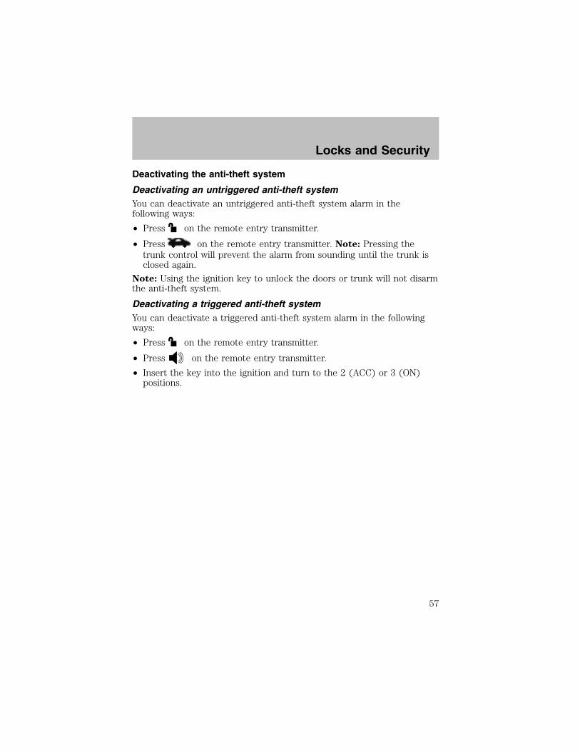
Deactivating the anti-theft system
Deactivating an untriggered anti-theft systemYou can deactivate an untriggered anti-theft system alarm in thefollowing ways:
• Press on the remote entry transmitter.
• Press on the remote entry transmitter. Note: Pressing thetrunk control will prevent the alarm from sounding until the trunk isclosed again.
Note: Using the ignition key to unlock the doors or trunk will not disarmthe anti-theft system.
Deactivating a triggered anti-theft systemYou can deactivate a triggered anti-theft system alarm in the followingways:
• Press on the remote entry transmitter.
• Press on the remote entry transmitter.
• Insert the key into the ignition and turn to the 2 (ACC) or 3 (ON)positions.
Locks and Security
57
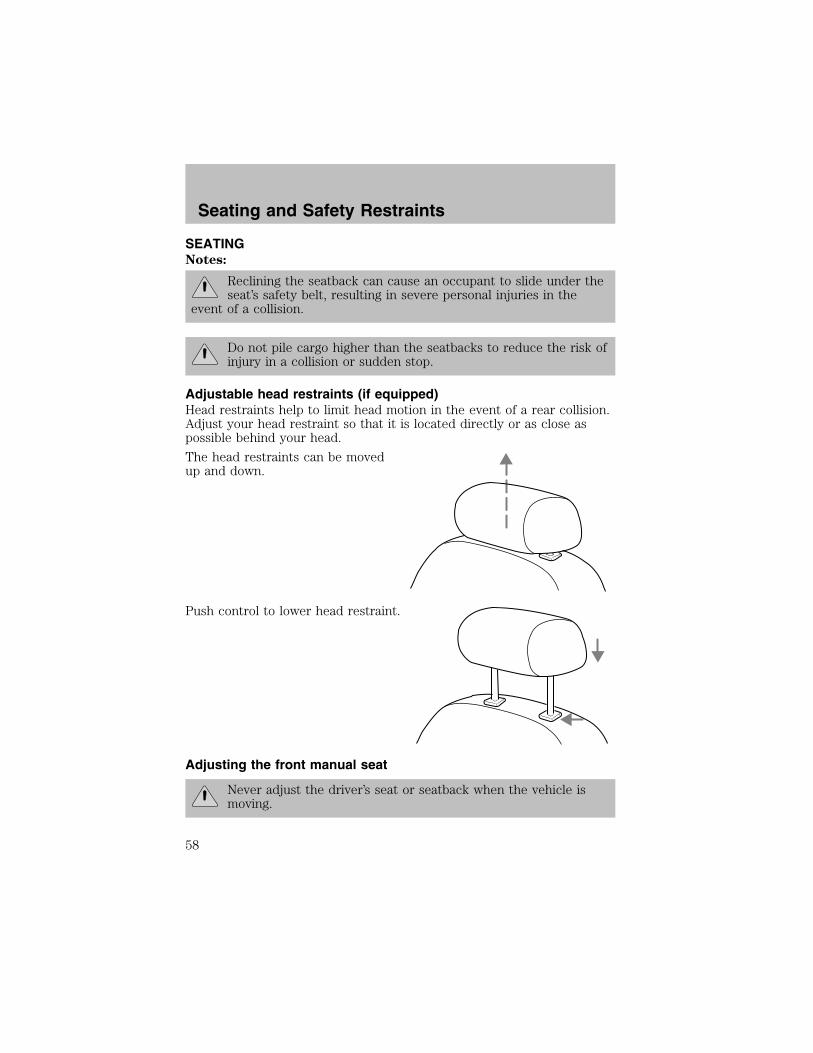
SEATINGNotes:
Reclining the seatback can cause an occupant to slide under theseat’s safety belt, resulting in severe personal injuries in the
event of a collision.
Do not pile cargo higher than the seatbacks to reduce the risk ofinjury in a collision or sudden stop.
Adjustable head restraints (if equipped)Head restraints help to limit head motion in the event of a rear collision.Adjust your head restraint so that it is located directly or as close aspossible behind your head.
The head restraints can be movedup and down.
Push control to lower head restraint.
Adjusting the front manual seat
Never adjust the driver’s seat or seatback when the vehicle ismoving.
Seating and Safety Restraints
58
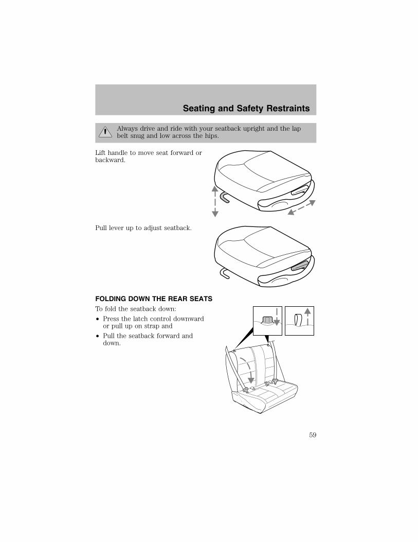
Always drive and ride with your seatback upright and the lapbelt snug and low across the hips.
Lift handle to move seat forward orbackward.
Pull lever up to adjust seatback.
FOLDING DOWN THE REAR SEATSTo fold the seatback down:
• Press the latch control downwardor pull up on strap and
• Pull the seatback forward anddown.
Seating and Safety Restraints
59

RETURNING THE SEAT TO THE UPRIGHT POSITION
Check to see that the seat and seatback is latched securely inposition. Keep floor area free of objects that would prevent
proper seat engagement. Never attempt to adjust the seat while thevehicle is in motion.
To return the seat to the upright/normal seating position:
• Rotate seat upward and latch.
The full rear bench seat is shown. The split-folding rear seat (ifequipped) operates in a similar manner.
SAFETY RESTRAINTS
Safety restraints precautions
Always drive and ride with your seatback upright and the lapbelt snug and low across the hips.
To reduce the risk of injury, make sure children sit where theycan be properly restrained.
Never let a passenger hold a child on his or her lap while thevehicle is moving. The passenger cannot protect the child from
injury in a collision.
All occupants of the vehicle, including the driver, should alwaysproperly wear their safety belts, even when an air bag (SRS) is
provided.
It is extremely dangerous to ride in a cargo area, inside oroutside of a vehicle. In a collision, people riding in these areas
are more likely to be seriously injured or killed. Do not allow people toride in any area of your vehicle that is not equipped with seats andsafety belts. Be sure everyone in your vehicle is in a seat and using asafety belt properly.
Seating and Safety Restraints
60
In a rollover crash, an unbelted person is significantly more likelyto die than a person wearing a safety belt.
Each seating position in your vehicle has a specific safety beltassembly which is made up of one buckle and one tongue that
are designed to be used as a pair. 1) Use the shoulder belt on theoutside shoulder only. Never wear the shoulder belt under the arm. 2)Never swing the safety belt around your neck over the inside shoulder.3) Never use a single belt for more than one person.
Always transport children 12 years old and under in the backseat and always properly use appropriate child restraints.
Safety belts and seats can become hot in a vehicle that has beenclosed up in sunny weather; they could burn a small child. Check
seat covers and buckles before you place a child anywhere near them.
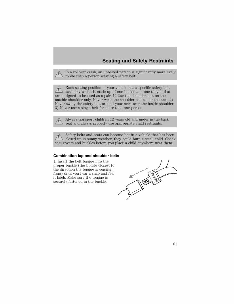
Combination lap and shoulder belts1. Insert the belt tongue into theproper buckle (the buckle closest tothe direction the tongue is comingfrom) until you hear a snap and feelit latch. Make sure the tongue issecurely fastened in the buckle.
Seating and Safety Restraints
61
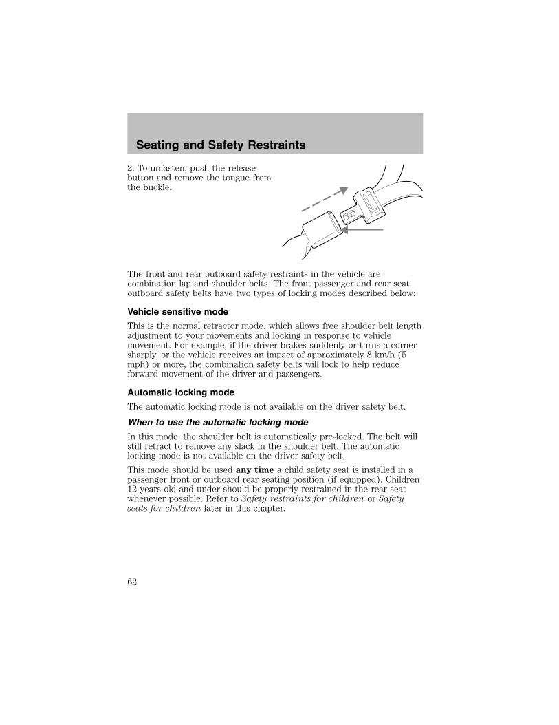
2. To unfasten, push the releasebutton and remove the tongue fromthe buckle.
The front and rear outboard safety restraints in the vehicle arecombination lap and shoulder belts. The front passenger and rear seatoutboard safety belts have two types of locking modes described below:
Vehicle sensitive mode
This is the normal retractor mode, which allows free shoulder belt lengthadjustment to your movements and locking in response to vehiclemovement. For example, if the driver brakes suddenly or turns a cornersharply, or the vehicle receives an impact of approximately 8 km/h (5mph) or more, the combination safety belts will lock to help reduceforward movement of the driver and passengers.
Automatic locking mode
The automatic locking mode is not available on the driver safety belt.
When to use the automatic locking mode
In this mode, the shoulder belt is automatically pre-locked. The belt willstill retract to remove any slack in the shoulder belt. The automaticlocking mode is not available on the driver safety belt.
This mode should be used any time a child safety seat is installed in apassenger front or outboard rear seating position (if equipped). Children12 years old and under should be properly restrained in the rear seatwhenever possible. Refer to Safety restraints for children or Safetyseats for children later in this chapter.
Seating and Safety Restraints
62
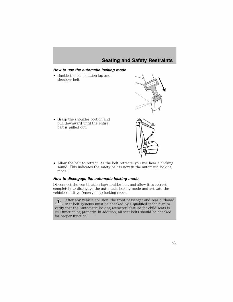
How to use the automatic locking mode• Buckle the combination lap andshoulder belt.
• Grasp the shoulder portion andpull downward until the entirebelt is pulled out.
• Allow the belt to retract. As the belt retracts, you will hear a clickingsound. This indicates the safety belt is now in the automatic lockingmode.
How to disengage the automatic locking mode
Disconnect the combination lap/shoulder belt and allow it to retractcompletely to disengage the automatic locking mode and activate thevehicle sensitive (emergency) locking mode.
After any vehicle collision, the front passenger and rear outboardseat belt systems must be checked by a qualified technician to
verify that the “automatic locking retractor” feature for child seats isstill functioning properly. In addition, all seat belts should be checkedfor proper function.
Seating and Safety Restraints
63
BELT AND RETRACTOR ASSEMBLY MUST BE REPLACED if theseat belt assembly “automatic locking retractor” feature or any
other seat belt function is not operating properly when checkedaccording to the procedures in Workshop Manual. Failure to replace theBelt and Retractor assembly could increase the risk of injury in collisions.
Safety belt extension assemblyIf the safety belt is too short when fully extended, there is a 20 cm (8inch) safety belt extension assembly that can be added (part number611C22). This assembly can be obtained from your dealer at no cost.
Use only extensions manufactured by the same supplier as the safetybelt. Manufacturer identification is located at the end of the webbing onthe label. Also, use the safety belt extension only if the safety belt is tooshort for you when fully extended.
Do not use extensions to change the fit of the shoulder beltacross the torso.
Safety belt warning light and indicator chime
The safety belt warning light illuminates in the instrument cluster and achime sounds to remind the occupants to fasten their safety belts.
Conditions of operation
If... Then...
The driver’s safety belt is notbuckled before the ignitionswitch is turned to the ONposition...
The safety belt warning lightilluminates 1-2 minutes and thewarning chime sounds 4-8 seconds.
The driver’s safety belt isbuckled while the indicatorlight is illuminated and thewarning chime is sounding...
The safety belt warning light andwarning chime turn off.
The driver’s safety belt isbuckled before the ignitionswitch is turned to the ONposition...
The safety belt warning light andindicator chime remain off.
Seating and Safety Restraints
64
BeltMinder
The BeltMinder feature is a supplemental warning to the safety beltwarning function. This feature provides additional reminders to thedriver that the driver’s safety belt is unbuckled by intermittentlysounding a chime and illuminating the safety belt warning lamp in theinstrument cluster.
If... Then...
The driver’s safety belt is notbuckled approximately 5seconds after the safety beltwarning light has turned off...
The BeltMinder feature is activated -the safety belt warning lightilluminates and the warning chimesounds for 6 seconds every 30seconds, repeating for approximately5 minutes or until safety belt isbuckled.
The driver’s safety belt isbuckled while the safety beltindicator light is illuminatedand the safety belt warningchime is sounding...
The BeltMinder feature will notactivate.
The driver’s safety belt isbuckled before the ignitionswitch is turned to the ONposition...
The BeltMinder feature will notactivate.
The following are reasons most often given for not wearing safety belts:(All statistics based on U.S. data)
Reasons given... Consider...
“Crashes are rare events” 36700 crashes occur every day. Themore we drive, the more we areexposed to “rare” events, even forgood drivers. 1 in 4 of us will be
seriously injured in a crash during
our lifetime.
“I’m not going far” 3 of 4 fatal crashes occur within 25
miles of home.
Seating and Safety Restraints
65

Reasons given... Consider...
“Belts are uncomfortable” We design our safety belts to enhancecomfort. If you are uncomfortable -try different positions for the safetybelt upper anchorage and seatbackwhich should be as upright aspossible; this can improve comfort.
“I was in a hurry” Prime time for an accident.
BeltMinder reminds us to take a fewseconds to buckle up.
“Seat belts don’t work” Safety belts, when used properly,reduce risk of death to front seatoccupants by 45% in cars, and by60% in light trucks.
“Traffic is light” Nearly 1 of 2 deaths occur in
single-vehicle crashes, many whenno other vehicles are around.
“Belts wrinkle my clothes” Possibly, but a serious crash can domuch more than wrinkle your clothes,particularly if you are unbelted.
“The people I’m with don’twear belts”
Set the example, teen deaths occur 4times more often in vehicles withTWO or MORE people. Children andyounger brothers/sisters imitatebehavior they see.
“I have an air bag” Air bags offer greater protection whenused with safety belts. Frontal airbagsare not designed to inflate in rear andside crashes or rollovers.
“I’d rather be thrown clear” Not a good idea. People who areejected are 40 times more likely
to DIE. Safety belts help preventejection, WE CAN’T “PICK OURCRASH”.
Seating and Safety Restraints
66

Do not sit on top of a buckled safety belt to avoid the BeltMinder chime. Sitting on the safety belt will increase the risk of
injury in an accident. To disable (one-time) or deactivate the BeltMinder feature please follow the directions stated below.
One time disableAny time the safety belt is buckled and then unbuckled during anignition ON cycle, BeltMinder will be disabled for that ignition cycle only.
Deactivating/activating the BeltMinder featureRead steps 1 - 9 thoroughly before proceeding with thedeactivation/activation programming procedure.
The BeltMinder feature can be deactivated/activated by performing thefollowing procedure:Before following the procedure, make sure that:• The parking brake is set.• The gearshift is in P (Park) (automatic transmission) or the neutralposition (manual transmission).
• The ignition switch is in the OFF position.• All vehicle doors are closed.• The driver’s safety belt is unbuckled.• The parklamps/headlamps are in OFF position (If vehicle is equippedwith Autolamps, this will not affect the procedure).
To reduce the risk of injury, do not deactivate/activate the BeltMinder feature while driving the vehicle.
BeltMinder activation and deactivation procedure
1. Turn the ignition switch to the RUN (or ON) position. (DO NOTSTART THE ENGINE.)
2. Wait until the safety belt warning light turns off. (Approximately 1–2minutes.)• Steps 3–5 must be completed within 60 seconds or the procedure willhave to be repeated.
3. Buckle then unbuckle the safety belt three times, ending with thesafety belt unbuckled. This can be done before or during BeltMinderwarning activation.
4. Turn on the parklamps/headlamps, turn off the parklamps/headlamps.
Seating and Safety Restraints
67
5. Buckle then unbuckle the safety belt three times, ending with thesafety belt unbuckled.• After step 5 the safety belt warning light will be turned on for threeseconds.
6. Within seven seconds of the safety belt warning light turning off,buckle then unbuckle the safety belt.• This will disable BeltMinder if it is currently enabled, or enableBeltMinder if it is currently disabled.
7. Confirmation of disabling BeltMinder is provided by the safety beltwarning light flashing four times per second for three seconds.8. Confirmation of enabling BeltMinder is provided by:• The safety belt warning light flashing four times per second for threeseconds.
• Followed by three seconds with the safety belt warning light off.• Once again, the safety belt warning light will flash four times persecond for three seconds.
9. After receiving confirmation, the deactivation/activation procedure iscomplete.
Safety belt maintenanceInspect the safety belt systems periodically to make sure they workproperly and are not damaged. Inspect the safety belts to make surethere are no nicks, tears or cuts. Replace if necessary. All safety beltassemblies, including retractors, buckles, front seat belt buckleassemblies, buckle support assemblies (slide bar-if equipped), shoulderbelt height adjusters (if equipped), shoulder belt guide on seatback (ifequipped), child safety seat LATCH and tether anchors, and attachinghardware, should be inspected after a collision. Ford Motor Companyrecommends that all safety belt assemblies used in vehicles involved in acollision be replaced. However, if the collision was minor and a qualifiedtechnician finds that the belts do not show damage and continue tooperate properly, they do not need to be replaced. Safety belt assembliesnot in use during a collision should also be inspected and replaced ifeither damage or improper operation is noted.
Failure to inspect and if necessary replace the safety beltassembly under the above conditions could result in severe
personal injuries in the event of a collision.
Refer to Interior in the Cleaning chapter.
Seating and Safety Restraints
68
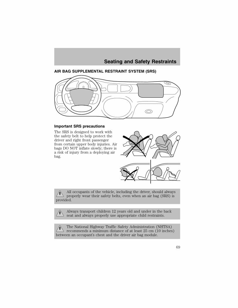
AIR BAG SUPPLEMENTAL RESTRAINT SYSTEM (SRS)
Important SRS precautionsThe SRS is designed to work withthe safety belt to help protect thedriver and right front passengerfrom certain upper body injuries. Airbags DO NOT inflate slowly; there isa risk of injury from a deploying airbag.
All occupants of the vehicle, including the driver, should alwaysproperly wear their safety belts, even when an air bag (SRS) is
provided.
Always transport children 12 years old and under in the backseat and always properly use appropriate child restraints.
The National Highway Traffic Safety Administration (NHTSA)recommends a minimum distance of at least 25 cm (10 inches)
between an occupant’s chest and the driver air bag module.
Seating and Safety Restraints
69

Never place your arm over the air bag module as a deploying airbag can result in serious arm fractures or other injuries.
To properly position yourself away from the air bag:
• Move your seat to the rear as far as you can while still reaching thepedals comfortably.
• Recline the seat slightly one or two degrees from the upright position.
Do not put anything on or over the air bag module. Placingobjects on or over the air bag inflation area may cause those
objects to be propelled by the air bag into your face and torso causingserious injury.
Do not attempt to service, repair, or modify the air bagsupplemental restraint systems or its fuses. See your Ford or
Lincoln Mercury dealer.
Modifying or adding equipment to the front end of the vehicle(including frame, bumper, front end body structure and tow
hooks) may affect the performance of the air bag system, increasingthe risk of injury. Do not modify the front end of the vehicle.
Seating and Safety Restraints
70

Children and air bagsChildren must always be properlyrestrained. Accident statisticssuggest that children are safer whenproperly restrained in the rearseating positions than in the frontseating position. Failure to followthese instructions may increase therisk of injury in a collision.
Air bags can kill or injure achild in a child seat.
NEVER place a rear-facing childseat in front of an active air bag. Ifyou must use a forward-facingchild seat in the front seat, movethe seat all the way back.
How does the air bag supplemental restraint system work?The air bag SRS is designed toactivate when the vehicle sustains alongitudinal deceleration sufficientto cause the air bag sensors to closean electrical circuit that initiates airbag inflation. The fact that the airbags did not inflate in a collisiondoes not mean that something iswrong with the system. Rather, itmeans the forces were not sufficientenough to cause activation. Air bagsare designed to inflate in frontal andnear-frontal collisions, not rollover, side-impact, or rear-impacts unlessthe collision causes sufficient longitudinal deceleration.
Seating and Safety Restraints
71

The air bags inflate and deflaterapidly upon activation. After air bagdeployment, it is normal to notice asmoke-like, powdery residue orsmell the burnt propellant. This mayconsist of cornstarch, talcumpowder or sodium compounds whichmay irritate the skin and eyes, butnone of the residue is toxic.
While the SRS is designed to helpreduce serious injuries, contact witha deploying air bag may also causeabrasions, swelling or temporaryhearing loss. Because air bags mustinflate rapidly and with considerableforce, there is the risk of death orserious injuries such as fractures, facial and eye injuries or internalinjuries, particularly to occupants who are not properly restrained or areotherwise out of position at the time of air bag deployment. It isextremely important that occupants be properly restrained as far awayfrom the air bag module as possible while maintaining vehicle control.The SRS consists of:• driver and passenger air bag modules (which include the inflators andair bags)
• one or more impact and safing sensors• a readiness light and tone• a diagnostic module• and the electrical wiring which connects the componentsThe diagnostic module monitors its own internal circuits and thesupplemental air bag electrical system warning (including the impactsensors), the system wiring, the air bag system readiness light, the airbag back up power and the air bag ignitors.
Several air bag system components get hot after inflation. Do nottouch them after inflation.
If the air bag has deployed, the air bag will not functionagain and must be replaced immediately. If the air bag is not
replaced, the unrepaired area will increase the risk of injury in acollision.
Seating and Safety Restraints
72

Determining if the system is operational
The SRS uses a readiness light in the instrument cluster or a tone toindicate the condition of the system. Refer to Air bag readiness sectionin the Instrument cluster chapter. Routine maintenance of the air bag isnot required.
A difficulty with the system is indicated by one or more of the following:
• The readiness light will eitherflash or stay lit.
• The readiness light will notilluminate immediately afterignition is turned on.
• A series of five beeps will be heard. The tone pattern will repeatperiodically until the problem and/or light are repaired.
If any of these things happen, even intermittently, have the SRS servicedat your dealership or by a qualified technician immediately. Unlessserviced, the system may not function properly in the event of acollision.
Disposal of air bags and air bag equipped vehicles
See your local dealership or qualified technician. Air bags MUST BEdisposed of by qualified personnel.
SAFETY RESTRAINTS FOR CHILDREN
See the following sections for directions on how to properly use safetyrestraints for children. Also see Air bag supplemental restraint system
(SRS) in this chapter for special instructions about using air bags.
Important child restraint precautions
You are required by law to use safety restraints for children in the U.S.and Canada. If small children (generally children who are four years oldor younger and who weigh 18 kg [40 lbs] or less) ride in your vehicle,you must put them in safety seats made especially for children. Checkyour local and state or provincial laws for specific requirementsregarding the safety of children in your vehicle. When possible, alwaysplace children under age 12 in the rear seat of your vehicle. Accidentstatistics suggest that children are safer when properly restrained in therear seating positions than in the front seating position.
Seating and Safety Restraints
73

Never let a passenger hold a child on his or her lap while thevehicle is moving. The passenger cannot protect the child from
injury in a collision.
Always follow the instructions and warnings that come with any infant orchild restraint you might use.
Children and safety beltsIf the child is the proper size, restrain the child in a safety seat. Childrenwho are too large for child safety seats (as specified by your child safetyseat manufacturer) should always wear safety belts.Follow all the important safety restraint and air bag precautions thatapply to adult passengers in your vehicle.If the shoulder belt portion of a combination lap and shoulder belt canbe positioned so it does not cross or rest in front of the child’s face orneck, the child should wear the lap and shoulder belt. Moving the childcloser to the center of the vehicle may help provide a good shoulder beltfit.
Do not leave children, unreliable adults, or pets unattended inyour vehicle.
Child booster seatsChildren outgrow a typical convertible or toddler seat when they weigh40 pounds and are around 4 years of age. Although the lap/shoulder beltwill provide some protection, these children are still too small forlap/shoulder belts to fit properly, which could increase the risk of seriousinjury.To improve the fit of both the lap and shoulder belt on children whohave outgrown child safety seats, Ford Motor Company recommends useof a belt-positioning booster.
Booster seats position a child so that safety belts fit better. They lift thechild up so that the lap belt rests low across the hips and the kneesbend comfortably. Booster seats also make the shoulder belt fit betterand more comfortably for growing children.
When children should use booster seats
Children need to use booster seats from the time they outgrow thetoddler seat until they are big enough for the vehicle seat andlap/shoulder belt to fit properly. Generally this is when they weigh about80 lbs (about 8 to 12 years old).
Seating and Safety Restraints
74
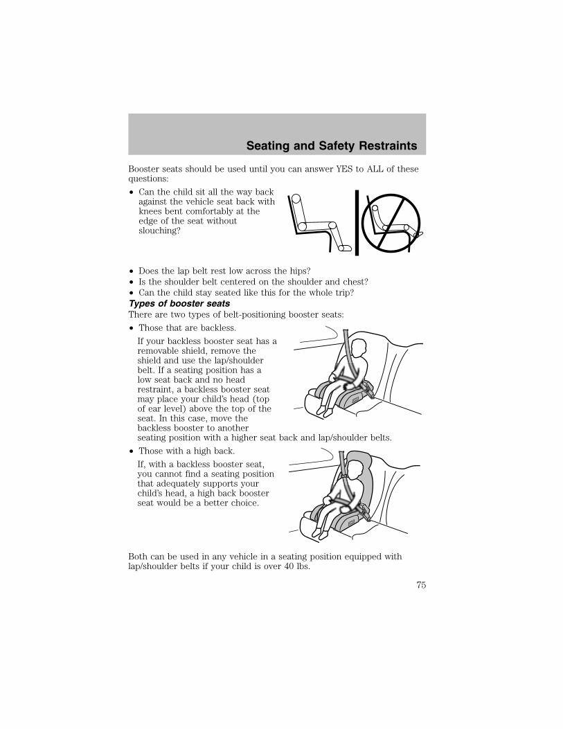
Booster seats should be used until you can answer YES to ALL of thesequestions:
• Can the child sit all the way backagainst the vehicle seat back withknees bent comfortably at theedge of the seat withoutslouching?
• Does the lap belt rest low across the hips?• Is the shoulder belt centered on the shoulder and chest?• Can the child stay seated like this for the whole trip?Types of booster seatsThere are two types of belt-positioning booster seats:
• Those that are backless.
If your backless booster seat has aremovable shield, remove theshield and use the lap/shoulderbelt. If a seating position has alow seat back and no headrestraint, a backless booster seatmay place your child’s head (topof ear level) above the top of theseat. In this case, move thebackless booster to anotherseating position with a higher seat back and lap/shoulder belts.
• Those with a high back.
If, with a backless booster seat,you cannot find a seating positionthat adequately supports yourchild’s head, a high back boosterseat would be a better choice.
Both can be used in any vehicle in a seating position equipped withlap/shoulder belts if your child is over 40 lbs.
Seating and Safety Restraints
75
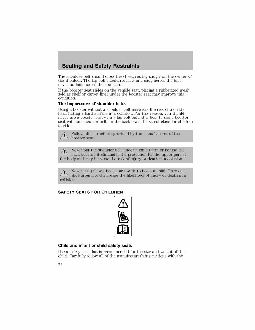
The shoulder belt should cross the chest, resting snugly on the center ofthe shoulder. The lap belt should rest low and snug across the hips,never up high across the stomach.If the booster seat slides on the vehicle seat, placing a rubberized meshsold as shelf or carpet liner under the booster seat may improve thiscondition.The importance of shoulder belts
Using a booster without a shoulder belt increases the risk of a child’shead hitting a hard surface in a collision. For this reason, you shouldnever use a booster seat with a lap belt only. It is best to use a boosterseat with lap/shoulder belts in the back seat- the safest place for childrento ride.
Follow all instructions provided by the manufacturer of thebooster seat.
Never put the shoulder belt under a child’s arm or behind theback because it eliminates the protection for the upper part of
the body and may increase the risk of injury or death in a collision.
Never use pillows, books, or towels to boost a child. They canslide around and increase the likelihood of injury or death in a
collision.
SAFETY SEATS FOR CHILDREN
Child and infant or child safety seatsUse a safety seat that is recommended for the size and weight of thechild. Carefully follow all of the manufacturer’s instructions with the
Seating and Safety Restraints
76

safety seat you put in your vehicle. If you do not install and use thesafety seat properly, the child may be injured in a sudden stop orcollision.
When installing a child safety seat:
• Review and follow the informationpresented in the Air bagsupplemental restraint system(SRS) section in this chapter.
• Use the correct safety belt bucklefor that seating position (thebuckle closest to the direction thetongue is coming from).
• Insert the belt tongue into theproper buckle until you hear asnap and feel it latch. Make sure the tongue is securely fastened in thebuckle.
• Keep the buckle release button pointing up and away from the safetyseat, with the tongue between the child seat and the release button,to prevent accidental unbuckling.
• Place seat back in upright position.
• Put the safety belt in the automatic locking mode. Refer to Automaticlocking mode (passenger side front and outboard rear seatingpositions) (if equipped) section in this chapter.
Ford recommends the use of a child safety seat having a top tetherstrap. Install the child safety seat in a seating position with a tetheranchor. For more information on top tether straps, refer to Attachingchild safety seats with tether straps in this chapter.
Carefully follow all of the manufacturer’s instructions includedwith the safety seat you put in your vehicle. If you do not install
and use the safety seat properly, the child may be injured in a suddenstop or collision.
Rear-facing child seats or infant carriers should never be placedin the front seats.
Seating and Safety Restraints
77
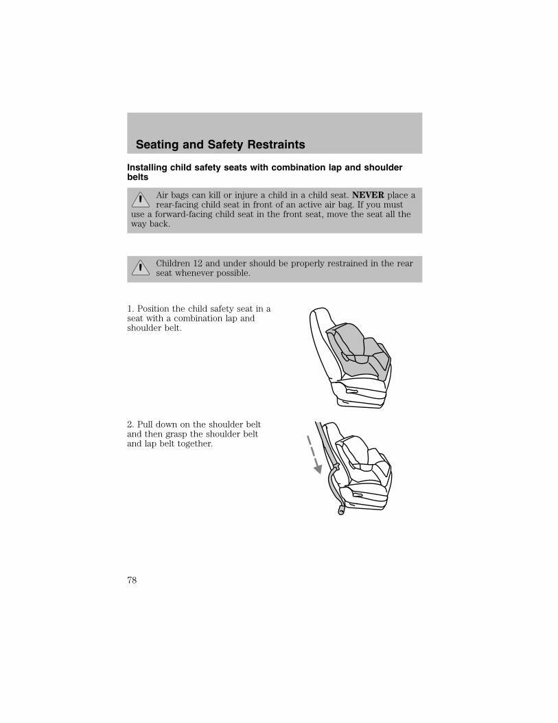
Installing child safety seats with combination lap and shoulderbelts
Air bags can kill or injure a child in a child seat. NEVER place arear-facing child seat in front of an active air bag. If you must
use a forward-facing child seat in the front seat, move the seat all theway back.
Children 12 and under should be properly restrained in the rearseat whenever possible.
1. Position the child safety seat in aseat with a combination lap andshoulder belt.
2. Pull down on the shoulder beltand then grasp the shoulder beltand lap belt together.
Seating and Safety Restraints
78

3. While holding the shoulder andlap belt portions together, route thetongue through the child seataccording to the child seatmanufacturer’s instructions. Be surethe belt webbing is not twisted.
4. Insert the belt tongue into theproper buckle (the buckle closest tothe direction the tongue is comingfrom) for that seating position untilyou hear a snap and feel the latchengage. Make sure the tongue islatched securely by pulling on it.
5. To put the retractor in theautomatic locking mode, grasp theshoulder portion of the belt and pulldownward until all of the belt ispulled out and a click is heard.
6. Allow the belt to retract. The belt will click as it retracts to indicate itis in the automatic locking mode.
Seating and Safety Restraints
79

7. Pull the lap belt portion acrossthe child seat toward the buckle andpull up on the shoulder belt whilepushing down with your knee on thechild seat.
8. Allow the safety belt to retract toremove any slack in the belt.
9. Before placing the child in theseat, forcibly move the seat forwardand back to make sure the seat issecurely held in place. To checkthis, grab the seat at the belt pathand attempt to move it side to sideand forward. There should be nomore than one inch of movement forproper installation.
10. Try to pull the belt out of the retractor to make sure the retractor isin the automatic locking mode (you should not be able to pull more beltout). If the retractor is not locked, unbuckle the belt and repeat stepstwo through nine.
Check to make sure the child seat is properly secured before each use.
Attaching child safety seats with tether straps
Most new forward-facing child safety seats include a tether strap whichgoes over the back of the seat and hooks to an anchoring point. Tetherstraps are available as an accessory for many older safety seats. Contactthe manufacturer of your child seat for information about ordering atether strap.
The rear seats of your vehicle are equipped with built-in tether strapanchors located behind the seats as described below.
The tether anchors in your vehicle are located below the rear windowmarked with the tether anchor symbol (shown with title).
Seating and Safety Restraints
80

The tether strap anchors in your vehicle are in the following positions(shown from top view):
Attach the tether strap onlyto the appropriate tether
anchor as shown. The tether strapmay not work properly if attachedsomewhere other than the correcttether anchor.
1. Position the child safety seat on the seat cushion.2. Route the child safety seat tether strap over the back of the seat.For vehicles with adjustable head restraints, route the tether strap underthe head restraint and between the head restraint posts, otherwise routethe tether strap over the top of the seatback.3. Locate the correct anchor for the selected seating position.4. Clip the tether strap to the anchor as shown.
If the tether strap is clipped incorrectly, the child safety seatmay not be retained properly in the event of a collision.
5. For further instructions to secure the child safety seat, refer to theInstalling child safety seats in combination lap and shoulder beltseating positions section of this chapter.6. Tighten the child safety seat tether strap according to themanufacturer’s instructions.
If the safety seat is not anchored properly, the risk of a childbeing injured in a collision greatly increases.
Seating and Safety Restraints
81

Attaching safety seats with LATCH (Lower Anchors and Tethers forChildren) attachments
Some child safety seats have two rigid or webbing mounted attachmentsthat connect to two anchors at certain seating positions in your vehicle.This type of child seat eliminates the need to use seat belts to attach thechild seat. For forward-facing child seats, the tether strap must also beattached to the proper tether anchor. See Attaching safety seats with
tether straps in this chapter.
Your vehicle has LATCH anchors for child seat installation at the seatingpositions marked with the child seat symbol.
Never attach two LATCHchild safety seats to the
same anchor. In a crash, oneanchor may not be strong enoughto hold two child safety seatattachments and may break,causing serious injury or death.
The lower anchors for child seatinstallation are located at the rearsection of the rear seat between thecushion and seat back.
Follow the child seat manufacturer’s instructions to properly install achild seat with LATCH attachments. Two plastic LATCH guides can beobtained at no charge from any Ford or Lincoln-Mercury dealer. Theysnap onto the LATCH lower anchors in the seat to help attach a childseat with rigid attachments. The guides hold the seat trim away toexpose the anchor and make it easier to attach some child seats.
Attach LATCH lower attachments of the child seat only to theanchors shown.
Seating and Safety Restraints
82

If you install a child seat with rigid LATCH attachments, do not tightenthe tether strap enough to lift the child seat off the vehicle seat cushionwhen the child is seated in it. Keep the tether strap just snug withoutlifting the front of the child seat. Keeping the child seat just touching thevehicle seat gives the best protection in a severe crash.
Each time you use the safety seat, check that the seat is properlyattached to the lower anchors and tether anchor. Try to tilt the childseat from side to side. Also try to tug the seat forward. Check to see ifthe anchors hold the seat in place.
If the safety seat is not anchored properly, the risk of a childbeing injured in a crash greatly increases.
Seating and Safety Restraints
83

STARTING
Positions of the ignition1. LOCK, locks the steering wheel,gearshift lever (automatic transaxleonly) and allows key removal. Onvehicles with a manual transaxlepush the key in while turning tolock.
2. ACCESSORY, allows the electricalaccessories such as the radio tooperate while the engine is notrunning.3. ON, all electrical circuits operational. Warning lights illuminated. Keyposition when driving.4. START, cranks the engine. Release the key as soon as the enginestarts.Preparing to start your vehicleEngine starting is controlled by the powertrain control system. Thissystem meets all Canadian Interference-Causing Equipment standardrequirements regulating the impulse electrical field strength of radionoise.When starting a fuel-injected engine, avoid pressing the acceleratorbefore or during starting. Only use the accelerator when you havedifficulty starting the engine. For more information on starting thevehicle, refer to Starting the engine in this chapter.
Extended idling at high engine speeds can produce very hightemperatures in the engine and exhaust system, creating the risk
of fire or other damage.
Do not park, idle, or drive your vehicle in dry grass or other dryground cover. The emission system heats up the engine
compartment and exhaust system, which can start a fire.
Do not start your vehicle in a closed garage or in other enclosedareas. Exhaust fumes can be toxic. Always open the garage door
before you start the engine. See Guarding against exhaust fumes inthis chapter for more instructions.
LOCK
AC
CON
STAR
T
0I
II
III
4
3
2
1
Driving
84
If you smell exhaust fumes inside your vehicle, have your dealerinspect your vehicle immediately. Do not drive if you smell
exhaust fumes.
Make sure the corresponding lights illuminate or illuminate briefly. If alight fails to illuminate, have the vehicle serviced.
• If the driver’s safety belt is fastened, the light may not illuminate.
Important safety precautions
When the engine starts, the idle RPM runs faster to warm the engine. Ifthe engine idle speed does not slow down automatically, have the vehiclechecked.
Before starting the vehicle:
1. Make sure all occupants buckle their safety belts. For moreinformation on safety belts and their proper usage, refer to the Seatingand safety restraints chapter.
2. Make sure the headlamps and electrical accessories are off.
If starting a vehicle with an automatic transaxle:
• Make sure the parking brake isset.
Driving
85
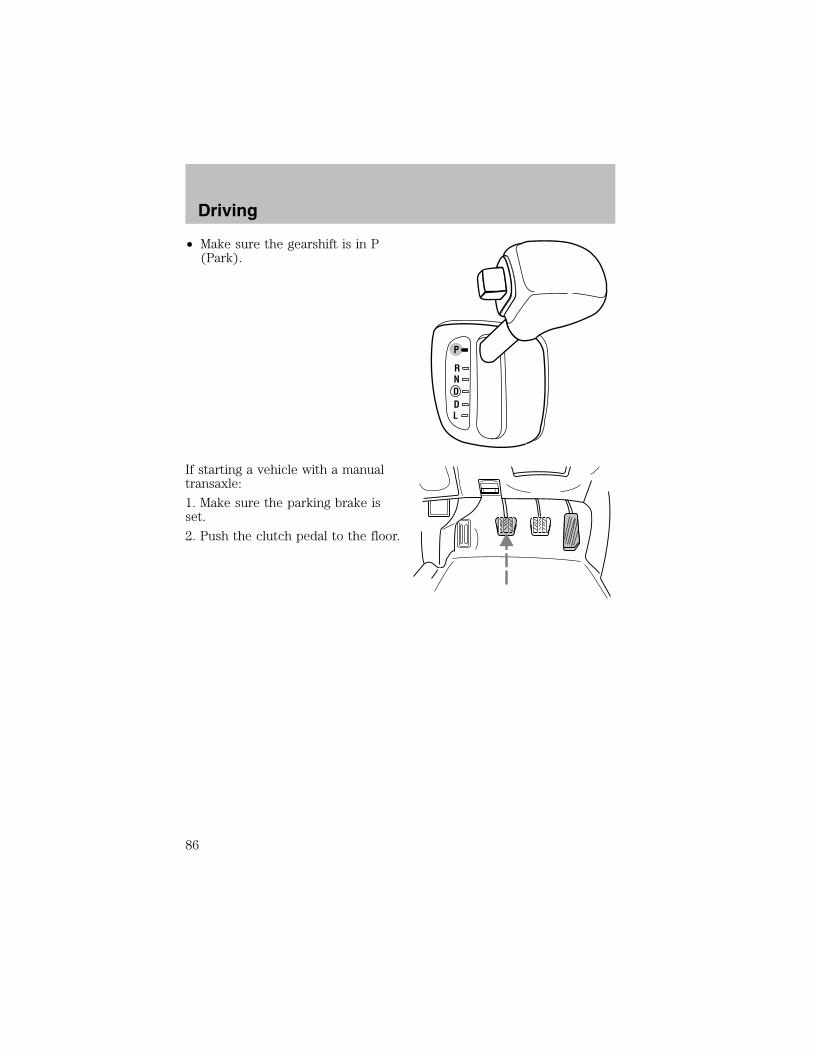
• Make sure the gearshift is in P(Park).
If starting a vehicle with a manualtransaxle:
1. Make sure the parking brake isset.
2. Push the clutch pedal to the floor.
P
RNDDL
Driving
86

• Turn the key to 3 (ON) withoutturning the key to 4 (START).
Make sure the corresponding lights illuminate or illuminate briefly. If alight fails to illuminate, have the vehicle serviced.• If the driver’s safety belt is fastened, the light may not illuminate.
Starting the engine1. Turn the key to 3 (ON) withoutturning the key to 4 (START). Ifthere is difficulty in turning the key,rotate the steering wheel until thekey turns freely. This condition mayoccur when:
• the front wheels are turned
• a front wheel is against the curb
Turn the key to 4 (START), thenrelease the key as soon as the engine starts. Excessive cranking coulddamage the starter.Note: If the engine does not start within five seconds on the first try,turn the key to 1 (LOCK), wait 10 seconds and try again.
LOCK
AC
CON
STAR
T
0I
II
III
4
3
2
1
!
THEFT
LOWFUEL
SERVICEENGINESOON
CHECKFUELCAP
PBRAKE ABS+–
MPH
20
5060 70
FUELFILL
E F C H12/ RPMx1000
12
34 5
678
30
40
80
90
100
110
12010 20
40
60
80
100 120
140
160
180
km/h
0
0
00 000
0 0 0
LOCK
AC
CON
STAR
T
0I
II
III
4
3
2
1
Driving
87

Using the engine block heater (if equipped)An engine block heater warms the engine coolant which aids in startingand heater/defroster performance. Use of an engine block heater isstrongly recommended if you live in a region where temperatures reach-23° C (-10° F) or below. For best results, plug the heater in at leastthree hours before starting the vehicle. The heater can be plugged in thenight before starting the vehicle.
To prevent electrical shock, do not use your heater withungrounded electrical systems or two-pronged (cheater)
adapters.
Guarding against exhaust fumesCarbon monoxide is present in exhaust fumes. Take precautions to avoidits dangerous effects.
If you smell exhaust fumes inside your vehicle, have your dealerinspect your vehicle immediately. Do not drive if you smell
exhaust fumes.
Important ventilating informationIf the engine is idling while the vehicle is stopped for a long period oftime, open the windows at least 2.5 cm (one inch) or adjust the heatingor air conditioning to bring in fresh air.
BRAKESYour service brakes are self-adjusting. Refer to the scheduledmaintenance guide for scheduled maintenance.
Occasional brake noise is normal and often does not indicate aperformance concern with the vehicle’s brake system. In normaloperation, automotive brake systems may emit occasional or intermittentsqueal or groan noises when the brakes are applied. Such noises areusually heard during the first few brake applications in the morning;however, they may be heard at any time while braking and can beaggravated by environmental conditions such as cold, heat, moisture,road dust, salt or mud. If a “metal-to-metal,” “continuous grinding” or“continuous squeal” sound is present while braking, the brake liningsmay be worn-out and should be inspected by a qualified servicetechnician.
Driving
88

If you are driving down a long or steep hill, shift to a lower gear.Do not apply your brakes continuously, as they may overheat
and become less effective.
Under normal operating conditions, brake dust may accumulate on thewheels. Some brake dust is inevitable as brakes wear and does notcontribute to brake noise. The use of modern friction materials withemphasis on improved performance and environmental considerationscan lead to more dust than in the past. Brake dust can be cleaned byweekly washing with soapy water and a soft sponge. Heavier deposits canbe removed with Motorcraft Wheel and Tire Cleaner (ZC-37–A).
Anti-lock brake system (ABS) (if equipped)On vehicles equipped with an anti-lock braking system (ABS), a noisefrom the hydraulic pump motor and pulsation in the pedal may beobserved during ABS braking events. Pedal pulsation coupled with noisewhile braking under panic conditions or on loose gravel, bumps, wet orsnowy roads is normal and indicates proper functioning of the vehicle’santi-lock brake system. The ABS performs a self-check after you startthe engine and begin to drive away. A brief mechanical noise may beheard during this test. This is normal. If a malfunction is found, the ABSwarning light will come on. If the vehicle has continuous vibration orshudder in the steering wheel while braking, the vehicle should beinspected by a qualified service technician.
The ABS operates by detecting theonset of wheel lockup during brakeapplications and compensates forthis tendency. The wheels areprevented from locking even whenthe brakes are firmly applied. Theaccompanying illustration depictsthe advantage of an ABS equippedvehicle (on bottom) to a non-ABSequipped vehicle (on top) during hard braking with loss of front brakingtraction.
Using ABS• In an emergency or when maximum efficiency from the four-wheelABS is required, apply continuous force on the brake. The four wheelABS will be activated immediately, thus allowing you to retain fullsteering control of your vehicle and, providing there is sufficientspace, will enable you to avoid obstacles and bring the vehicle to acontrolled stop.
Driving
89
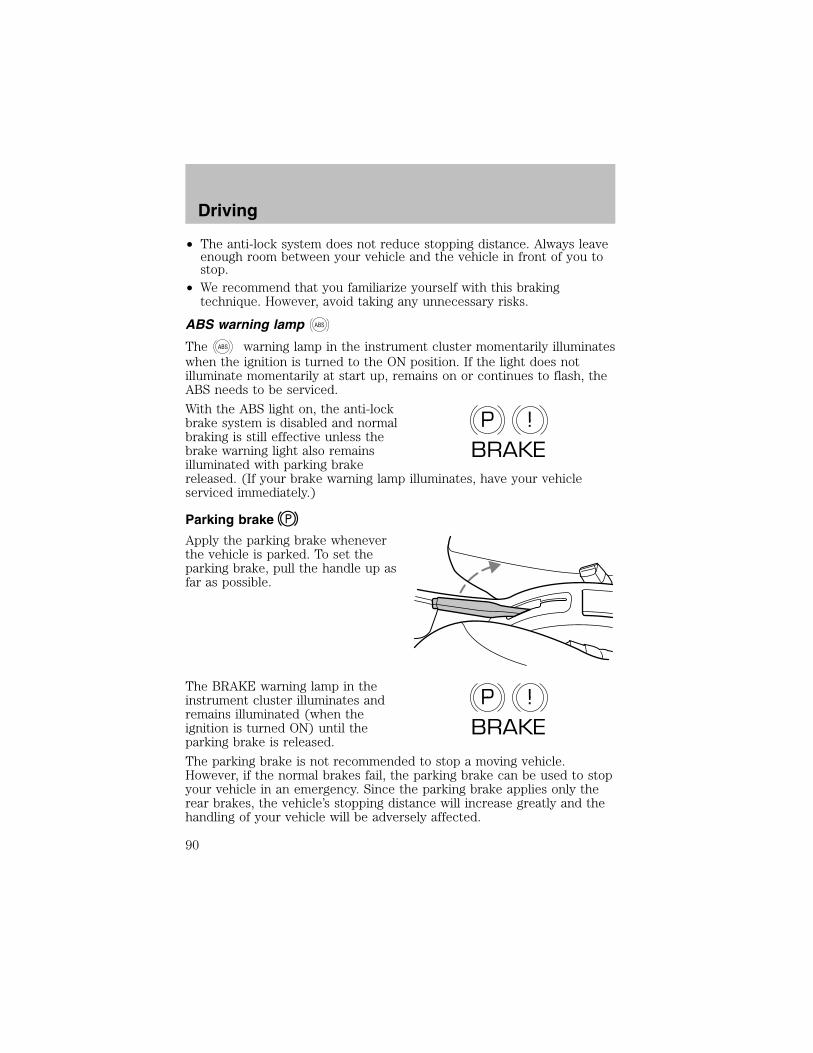
• The anti-lock system does not reduce stopping distance. Always leaveenough room between your vehicle and the vehicle in front of you tostop.
• We recommend that you familiarize yourself with this brakingtechnique. However, avoid taking any unnecessary risks.
ABS warning lamp ABS
The ABS warning lamp in the instrument cluster momentarily illuminateswhen the ignition is turned to the ON position. If the light does notilluminate momentarily at start up, remains on or continues to flash, theABS needs to be serviced.
With the ABS light on, the anti-lockbrake system is disabled and normalbraking is still effective unless thebrake warning light also remainsilluminated with parking brakereleased. (If your brake warning lamp illuminates, have your vehicleserviced immediately.)
Parking brake
Apply the parking brake wheneverthe vehicle is parked. To set theparking brake, pull the handle up asfar as possible.
The BRAKE warning lamp in theinstrument cluster illuminates andremains illuminated (when theignition is turned ON) until theparking brake is released.
The parking brake is not recommended to stop a moving vehicle.However, if the normal brakes fail, the parking brake can be used to stopyour vehicle in an emergency. Since the parking brake applies only therear brakes, the vehicle’s stopping distance will increase greatly and thehandling of your vehicle will be adversely affected.
P !BRAKE
P !BRAKE
Driving
90
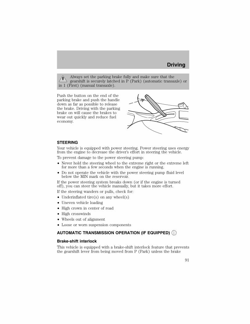
Always set the parking brake fully and make sure that thegearshift is securely latched in P (Park) (automatic transaxle) or
in 1 (First) (manual transaxle).
Push the button on the end of theparking brake and push the handledown as far as possible to releasethe brake. Driving with the parkingbrake on will cause the brakes towear out quickly and reduce fueleconomy.
STEERINGYour vehicle is equipped with power steering. Power steering uses energyfrom the engine to decrease the driver’s effort in steering the vehicle.To prevent damage to the power steering pump:• Never hold the steering wheel to the extreme right or the extreme leftfor more than a few seconds when the engine is running.
• Do not operate the vehicle with the power steering pump fluid levelbelow the MIN mark on the reservoir.
If the power steering system breaks down (or if the engine is turnedoff), you can steer the vehicle manually, but it takes more effort.If the steering wanders or pulls, check for:• Underinflated tire(s) on any wheel(s)• Uneven vehicle loading• High crown in center of road• High crosswinds• Wheels out of alignment• Loose or worn suspension components
AUTOMATIC TRANSMISSION OPERATION (IF EQUIPPED)
Brake-shift interlockThis vehicle is equipped with a brake-shift interlock feature that preventsthe gearshift lever from being moved from P (Park) unless the brake
Driving
91
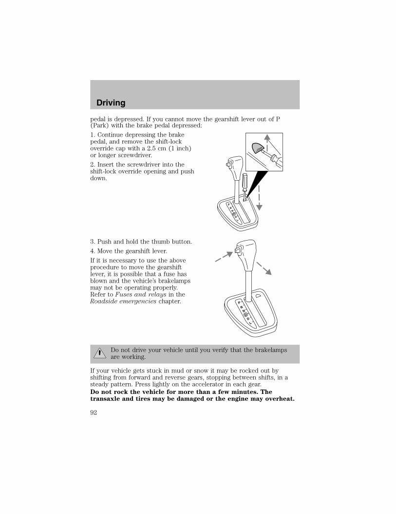
pedal is depressed. If you cannot move the gearshift lever out of P(Park) with the brake pedal depressed:
1. Continue depressing the brakepedal, and remove the shift-lockoverride cap with a 2.5 cm (1 inch)or longer screwdriver.
2. Insert the screwdriver into theshift-lock override opening and pushdown.
3. Push and hold the thumb button.
4. Move the gearshift lever.
If it is necessary to use the aboveprocedure to move the gearshiftlever, it is possible that a fuse hasblown and the vehicle’s brakelampsmay not be operating properly.Refer to Fuses and relays in theRoadside emergencies chapter.
Do not drive your vehicle until you verify that the brakelampsare working.
If your vehicle gets stuck in mud or snow it may be rocked out byshifting from forward and reverse gears, stopping between shifts, in asteady pattern. Press lightly on the accelerator in each gear.Do not rock the vehicle for more than a few minutes. Thetransaxle and tires may be damaged or the engine may overheat.
PR
ND
DL
PR
ND
DL
Driving
92
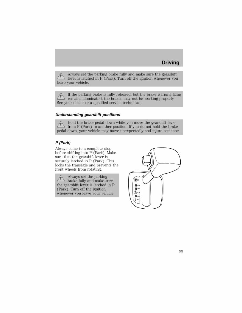
Always set the parking brake fully and make sure the gearshiftlever is latched in P (Park). Turn off the ignition whenever you
leave your vehicle.
If the parking brake is fully released, but the brake warning lampremains illuminated, the brakes may not be working properly.
See your dealer or a qualified service technician.
Understanding gearshift positions
Hold the brake pedal down while you move the gearshift leverfrom P (Park) to another position. If you do not hold the brake
pedal down, your vehicle may move unexpectedly and injure someone.
P (Park)Always come to a complete stopbefore shifting into P (Park). Makesure that the gearshift lever issecurely latched in P (Park). Thislocks the transaxle and prevents thefront wheels from rotating.
Always set the parkingbrake fully and make sure
the gearshift lever is latched in P(Park). Turn off the ignitionwhenever you leave your vehicle.
P
RNDDL
Driving
93

R (Reverse)With the gearshift lever in R(Reverse), the vehicle will movebackward. You should always cometo a complete stop before shifting inand out of R (Reverse).
N (Neutral)With the gearshift lever in the N(Neutral) position, the vehicle canbe started and is free to roll. Holdthe brake pedal down while in thisposition.
P
RNDDL
P
RNDDL
Driving
94

(Overdrive)
The overdrive position is the normaldriving position for an automaticoverdrive transaxle. It works thesame way as D (Drive) but shifts toa fourth gear-an overdrivegear-when your vehicle cruises at aconstant speed for any length oftime. This fourth gear will increaseyour fuel economy when you travelat cruising speeds
Overdrive may not be appropriate for certain terrains. If the transaxleshifts back and forth between third and fourth gears while you aredriving hilly roads or if your vehicle requires additional power forclimbing hills, shift into D (Drive).
D (Drive)D (Drive) eliminates the needlessshifting between third and fourthgears that your vehicle may dowhen driving in hilly terrain. It alsogives more engine braking thanoverdrive to slow your vehicle ondowngrades.
P
RNDDL
P
RNDDL
Driving
95
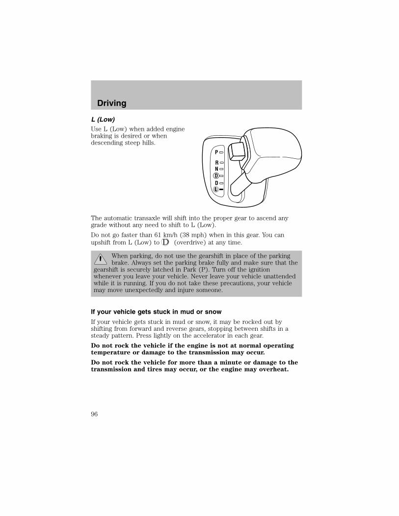
L (Low)Use L (Low) when added enginebraking is desired or whendescending steep hills.
The automatic transaxle will shift into the proper gear to ascend anygrade without any need to shift to L (Low).
Do not go faster than 61 km/h (38 mph) when in this gear. You canupshift from L (Low) to (overdrive) at any time.
When parking, do not use the gearshift in place of the parkingbrake. Always set the parking brake fully and make sure that the
gearshift is securely latched in Park (P). Turn off the ignitionwhenever you leave your vehicle. Never leave your vehicle unattendedwhile it is running. If you do not take these precautions, your vehiclemay move unexpectedly and injure someone.
If your vehicle gets stuck in mud or snow
If your vehicle gets stuck in mud or snow, it may be rocked out byshifting from forward and reverse gears, stopping between shifts in asteady pattern. Press lightly on the accelerator in each gear.
Do not rock the vehicle if the engine is not at normal operatingtemperature or damage to the transmission may occur.
Do not rock the vehicle for more than a minute or damage to thetransmission and tires may occur, or the engine may overheat.
P
RNDDL
Driving
96
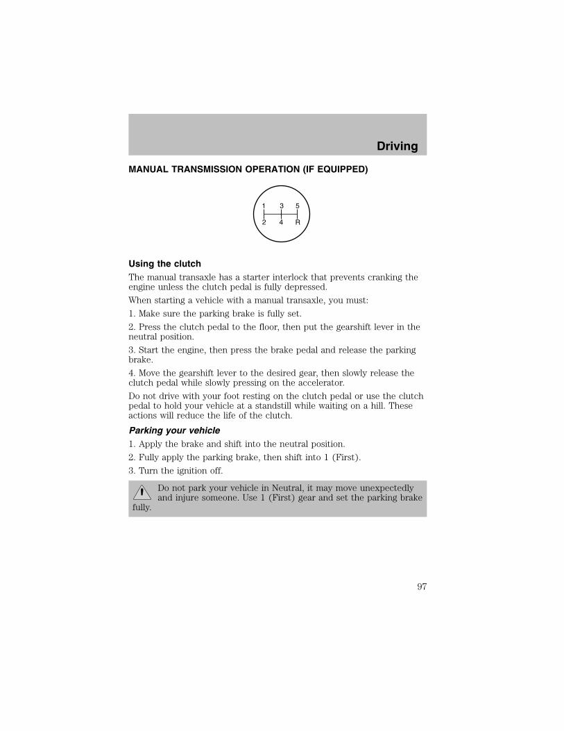
MANUAL TRANSMISSION OPERATION (IF EQUIPPED)
Using the clutchThe manual transaxle has a starter interlock that prevents cranking theengine unless the clutch pedal is fully depressed.
When starting a vehicle with a manual transaxle, you must:
1. Make sure the parking brake is fully set.
2. Press the clutch pedal to the floor, then put the gearshift lever in theneutral position.
3. Start the engine, then press the brake pedal and release the parkingbrake.
4. Move the gearshift lever to the desired gear, then slowly release theclutch pedal while slowly pressing on the accelerator.
Do not drive with your foot resting on the clutch pedal or use the clutchpedal to hold your vehicle at a standstill while waiting on a hill. Theseactions will reduce the life of the clutch.
Parking your vehicle1. Apply the brake and shift into the neutral position.
2. Fully apply the parking brake, then shift into 1 (First).
3. Turn the ignition off.
Do not park your vehicle in Neutral, it may move unexpectedlyand injure someone. Use 1 (First) gear and set the parking brake
fully.
1 3 5
2 4 R
Driving
97
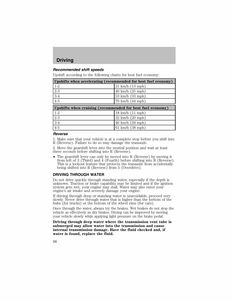
Recommended shift speedsUpshift according to the following charts for best fuel economy:
Upshifts when accelerating (recommended for best fuel economy)
1-2 21 km/h (13 mph)2-3 40 km/h (25 mph)3-4 53 km/h (33 mph)4-5 70 km/h (44 mph)
Upshifts when cruising (recommended for best fuel economy)
1-2 18 km/h (11 mph)2-3 32 km/h (20 mph)3-4 46 km/h (29 mph)4-5 61 km/h (38 mph)
Reverse1. Make sure that your vehicle is at a complete stop before you shift intoR (Reverse). Failure to do so may damage the transaxle.2. Move the gearshift lever into the neutral position and wait at leastthree seconds before shifting into R (Reverse).• The gearshift lever can only be moved into R (Reverse) by moving itfrom left of 3 (Third) and 4 (Fourth) before shifting into R (Reverse).This is a lockout feature that protects the transaxle from accidentallybeing shifted into R (Reverse) from 5 (Overdrive).
DRIVING THROUGH WATERDo not drive quickly through standing water, especially if the depth isunknown. Traction or brake capability may be limited and if the ignitionsystem gets wet, your engine may stall. Water may also enter yourengine’s air intake and severely damage your engine.If driving through deep or standing water is unavoidable, proceed veryslowly. Never drive through water that is higher than the bottom of thehubs (for trucks) or the bottom of the wheel rims (for cars).Once through the water, always try the brakes. Wet brakes do not stop thevehicle as effectively as dry brakes. Drying can be improved by movingyour vehicle slowly while applying light pressure on the brake pedal.
Driving through deep water where the transmission vent tube issubmerged may allow water into the transmission and causeinternal transmission damage. Have the fluid checked and, ifwater is found, replace the fluid.
Driving
98

VEHICLE LOADING
Before loading a vehicle, familiarize yourself with the following terms:
• Base Curb Weight: Weight of the vehicle including any standardequipment, fluids, lubricants, etc. It does not include occupants oraftermarket equipment.
• Payload: Combined maximum allowable weight of cargo, occupantsand optional equipment. The payload equals the gross vehicle weightrating minus base curb weight.
• GVW (Gross Vehicle Weight): Base curb weight plus payloadweight. The GVW is not a limit or a specification.
• GVWR (Gross Vehicle Weight Rating): Maximum permissible totalweight of the base vehicle, occupants, optional equipment and cargo.The GVWR is specific to each vehicle and is listed on the SafetyCertification Label on the driver’s door pillar.
• GAWR (Gross Axle Weight Rating): Carrying capacity for each axlesystem. The GAWR is specific to each vehicle and is listed on theSafety Certification Label on the driver’s door pillar.
• GCW (Gross Combined Weight): The combined weight of thetowing vehicle (including occupants and cargo) and the loaded trailer.
• GCWR (Gross Combined Weight Rating): Maximum permissiblecombined weight of towing vehicle (including occupants and cargo)and the loaded trailer
• Maximum Trailer Weight Rating: Maximum weight of a trailer thevehicle is permitted to tow. The maximum trailer weight rating isdetermined by subtracting the vehicle curb weight for eachengine/transmission combination, any required option weight for trailertowing and the weight of the driver from the GCWR for the towingvehicle.
• Maximum Trailer Weight: Maximum weight of a trailer the loadedvehicle (including occupants and cargo) is permitted to tow. It isdetermined by subtracting the weight of the loaded trailer towingvehicle from the GCWR for the towing vehicle.
• Trailer Weight Range: Specified weight range that the trailer mustfall within that ranges from zero to the maximum trailer weight rating.
Remember to figure in the tongue load of your loaded trailer whenfiguring the total weight.
Driving
99

Do not exceed the GVWR or the GAWR specified on thecertification label.
Do not use replacement tires with lower load carrying capacities than theoriginals because they may lower the vehicle’s GVWR and GAWRlimitations. Replacement tires with a higher limit than the originals donot increase the GVWR and GAWR limitations.
The Safety Certification Label, found on the driver’s door pillar, listsseveral important vehicle weight rating limitations. Before adding anyadditional equipment, refer to these limitations. If you are adding weightto the front of your vehicle, (potentially including weight added to thecab), the weight added should not exceed the front axle reserve capacity(FARC). Additional frontal weight may be added to the front axle reservecapacity provided you limit your payload in other ways (i.e. restrict thenumber of occupants or amount of cargo carried).
Always ensure that the weight of occupants, cargo and equipment beingcarried is within the weight limitations that have been established foryour vehicle including both gross vehicle weight and front and rear grossaxle weight rating limits. Under no circumstance should these limitationsbe exceeded.
Exceeding any vehicle weight rating limitation could result inserious damage to the vehicle loss of vehicle control, vehicle
rollover, and/or personal injury.
TRAILER TOWING
Your vehicle is capable of towing a trailer up to 454 kg (1,000 lbs.) grosstrailer weight with a maximum tongue load of 45 kg (100 lbs.). Do nottow a trailer until your vehicle has been driven at least 800 km (500miles).
Towing a trailer places an additional load on your vehicle’s engine,transaxle, brakes, tires and suspension. Inspect these componentscarefully after towing.
Do not exceed the GVWR or the GAWR specified on thecertification label.
Driving
100
Towing trailers beyond the maximum recommended gross trailerweight exceeds the limit of the vehicle and could result in
engine damage, transaxle damage, structural damage, increased risk ofloss of vehicle control, vehicle rollover and/or serious personal injury.
Preparing to towUse the proper equipment for towing a trailer and make sure it isproperly attached to your vehicle. See your dealer or a reliable trailerdealer if you require assistance.
HitchesDo not use hitches that clamp onto the vehicle bumper. Use a loadcarrying hitch. You must distribute the load in your trailer so that10–15% of the total weight of the trailer is on the tongue.
Safety chainsAlways connect the trailer’s safety chains to the frame or hook retainersof the vehicle hitch. To connect the trailer’s safety chains, cross thechains under the trailer tongue and allow slack for turning corners.If you use a rental trailer, follow the instructions that the rental agencygives to you.Do not attach safety chains to the bumper.
Trailer brakesElectric brakes and manual, automatic or surge-type trailer brakes aresafe if installed properly and adjusted to the manufacturer’sspecifications. The trailer brakes must meet local and Federalregulations.
Do not connect a trailer’s hydraulic brake system directly to yourvehicle’s brake system. Your vehicle may not have enough
braking power and your chances of having a collision greatly increase.
The braking system of the tow vehicle is rated for operation at theGVWR not GCWR.
Trailer lampsTrailer lamps are required on most towed vehicles. Make sure your trailerlamps conform to local and Federal regulations. See your dealer or trailerrental agency for proper instructions and equipment for hooking up trailerlamps.
Driving
101
Driving while you towWhen towing a trailer:• Turn off the speed control. The speed control may shut offautomatically when you are towing on long, steep grades.
• Consult your local motor vehicle speed regulations for towing a trailer.
• To eliminate excessive shifting, use a lower gear. This will also assistin transaxle cooling.
• Anticipate stops and brake gradually.
• Do not exceed the GCWR rating or transaxle damage may occur.
Servicing after towingIf you tow a trailer for long distances, your vehicle will require morefrequent service intervals. Refer to your scheduled maintenance guide formore information.
Trailer towing tips• Practice turning, stopping and backing up before starting on a trip toget the feel of the vehicle trailer combination. When turning, makewider turns so the trailer wheels will clear curbs and other obstacles.
• Allow more distance for stopping with a trailer attached.
• If you are driving down a long or steep hill, shift to a lower gear. Donot apply the brakes continuously, as they may overheat and becomeless effective.
• The trailer tongue weight should be 10–15% of the loaded trailerweight.
• After you have traveled 80 km (50 miles), thoroughly check yourhitch, electrical connections and trailer wheel lug nuts.
• To aid in engine/transmission cooling and A/C efficiency during hotweather while stopped in traffic, place the gearshift lever in P (Park).
• Vehicles with trailers should not be parked on a grade. If you mustpark on a grade, place wheel chocks under the trailer’s wheels.
TOWING BEHIND ANOTHER VEHICLEIf your vehicle has an automatic transaxle, it cannot be flat-towed withall wheels on the ground; front wheel dollies must be used.
If your vehicle has an manual transaxle, your vehicle can be flat-towedwith all wheels on the ground.
Driving
102

GETTING ROADSIDE ASSISTANCETo fully assist you should you have a vehicle concern, Ford MotorCompany offers a complimentary roadside assistance program. Thisprogram is separate from the New Vehicle Limited Warranty. The serviceis available:• 24–hours, seven days a week• for the New Vehicle Limited Warranty period of three years or 60,000km (36,000 miles), whichever occurs first on Ford and Mercuryvehicles, and four years or 80,000 km (50,000 miles) on Lincolnvehicles.
Roadside assistance will cover:• changing a flat tire• jump-starts• lock-out assistance• limited fuel delivery
• towing of your disabled vehicle to the nearest Ford Motor Companydealership, or your selling dealer if within 56.3 km (35 miles) of thenearest Ford Motor Company dealership (one tow per disablement).Even non-warranty related tows, like accidents or getting stuck in themud or snow, are covered (some exclusions apply, such as impoundtowing or repossession).
Canadian customers refer to your Owner Information Guide forinformation on:
• coverage period
• exact fuel amounts
• towing of your disabled vehicle
• emergency travel expense reimbursement
• travel planning benefits
USING ROADSIDE ASSISTANCEComplete the roadside assistance identification card and place it in yourwallet for quick reference. In the United States, this card is found in theOwner Guide portfolio in the glove compartment in Ford vehicles and ismailed to you if you own a Mercury or Lincoln. In Canada, the card isfound in the Owner Information Guide in the glove compartment.
U.S. Ford or Mercury vehicle customers who require roadside assistance,call 1–800–241–3673; Lincoln vehicle customers call 1–800–521–4140.
Roadside Emergencies
103
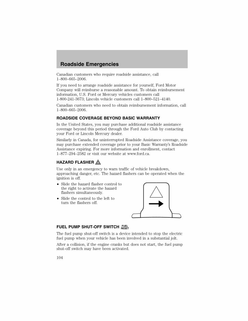
Canadian customers who require roadside assistance, call1–800–665–2006.
If you need to arrange roadside assistance for yourself, Ford MotorCompany will reimburse a reasonable amount. To obtain reimbursementinformation, U.S. Ford or Mercury vehicles customers call1-800-241-3673; Lincoln vehicle customers call 1–800–521–4140.
Canadian customers who need to obtain reimbursement information, call1–800–665–2006.
ROADSIDE COVERAGE BEYOND BASIC WARRANTY
In the United States, you may purchase additional roadside assistancecoverage beyond this period through the Ford Auto Club by contactingyour Ford or Lincoln Mercury dealer.
Similarly in Canada, for uninterrupted Roadside Assistance coverage, youmay purchase extended coverage prior to your Basic Warranty’s RoadsideAssistance expiring. For more information and enrollment, contact1–877–294–2582 or visit our website at www.ford.ca.
HAZARD FLASHER
Use only in an emergency to warn traffic of vehicle breakdown,approaching danger, etc. The hazard flashers can be operated when theignition is off.
• Slide the hazard flasher control tothe right to activate the hazardflashers simultaneously.
• Slide the control to the left toturn the flashers off.
FUEL PUMP SHUT-OFF SWITCH FUELRESET
The fuel pump shut-off switch is a device intended to stop the electricfuel pump when your vehicle has been involved in a substantial jolt.
After a collision, if the engine cranks but does not start, the fuel pumpshut-off switch may have been activated.
Roadside Emergencies
104

The fuel pump shut-off switch islocated in the driver’s foot well,behind the kick panel.
Use the following procedure to reset the fuel pump shut-off switch.1. Turn the ignition to the OFF position.2. Check the fuel system for leaks.3. If no fuel leak is apparent, reset the fuel pump shut-off switch bypushing in on the reset button.
4. Turn the ignition to the ON position. Pause for a few seconds andreturn the key to the OFF position.
5. Make a further check for leaks in the fuel system.
FUSES AND RELAYS
FusesIf electrical components in thevehicle are not working, a fuse mayhave blown. Blown fuses areidentified by a broken wire withinthe fuse. Check the appropriatefuses before replacing any electricalcomponents.
15
Roadside Emergencies
105

Note: Always replace a fuse with one that has the specified amperagerating. Using a fuse with a higher amperage rating can cause severe wiredamage and could start a fire.
Standard fuse amperage rating and color
COLOR
Fuse
rating
Mini
fuses
Standard
fuses
Maxi
fuses
Cartridge
maxi
fuses
Fuse link
cartridge
2A Grey Grey — — —3A Violet Violet — — —4A Pink Pink — — —5A Tan Tan — — —7.5A Brown Brown — — —10A Red Red — — —15A Blue Blue — — —20A Yellow Yellow Yellow Blue Blue25A Natural Natural — — —30A Green Green Green Pink Pink40A — — Orange Green Green50A — — Red Red Red60A — — Blue — Yellow70A — — Tan — Brown80A — — Natural — Black
Roadside Emergencies
106

Passenger compartment fuse panel
The fuses are coded as follows:
Fuse/Relay
Location
Fuse Amp
Rating
Passenger Compartment Fuse
Panel Description
DRL 10A Daytime Running Lamps (DRL)HAZARD 15A Hazard flasherROOM 10A Engine controls, RAP system,
Radio, Shift lock, Courtesy lamps,Starting system, Warning chime,Instrument cluster
ENGINE 15A Electronic automatic transaxle,Ignition system, Constant controlrelay module (PCM relay)
RADIO 5A Power mirrors, Radio, RAP systemDOOR LOCK 30A Power door locksHORN 15A Horn, Shift lock
AIR COND 15A A/C-heater, ABSMETER 10A Backup lamps, Engine coolant
level switch, Instrument cluster,Rear window defrost, Shift lock,Warning chime, Turn signal switch
(DRL) (DOOR LK) STOP
HAZARD HORN TAIL
ROOM (AIR COND) (SUN ROOF)
ENGINE METER (ASC)
RADIO WIPER –
P. Window (C.B.)
(FOG)CIGAR
(AUDIO)AIR BAG
FUEL INJ
HEATER
–
Roadside Emergencies
107
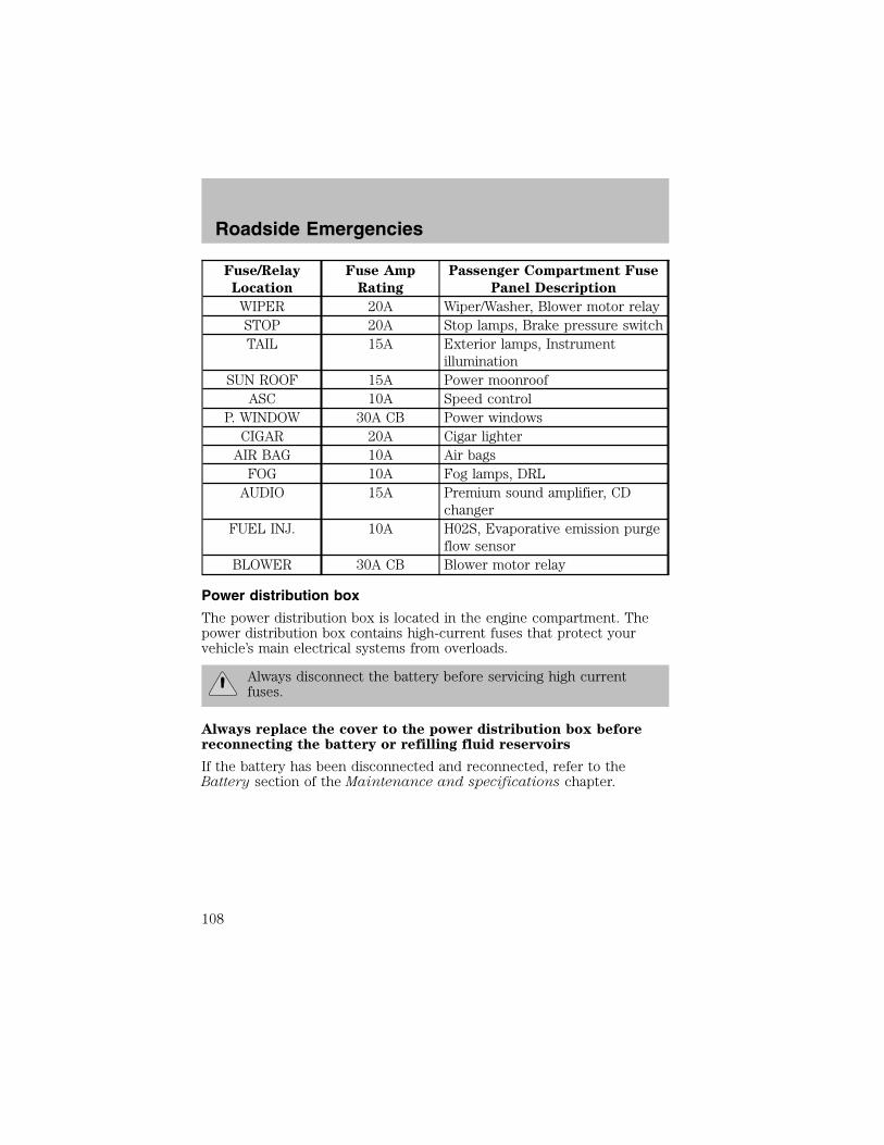
Fuse/Relay
Location
Fuse Amp
Rating
Passenger Compartment Fuse
Panel Description
WIPER 20A Wiper/Washer, Blower motor relaySTOP 20A Stop lamps, Brake pressure switchTAIL 15A Exterior lamps, Instrument
illuminationSUN ROOF 15A Power moonroofASC 10A Speed control
P. WINDOW 30A CB Power windowsCIGAR 20A Cigar lighterAIR BAG 10A Air bagsFOG 10A Fog lamps, DRLAUDIO 15A Premium sound amplifier, CD
changerFUEL INJ. 10A H02S, Evaporative emission purge
flow sensorBLOWER 30A CB Blower motor relay
Power distribution box
The power distribution box is located in the engine compartment. Thepower distribution box contains high-current fuses that protect yourvehicle’s main electrical systems from overloads.
Always disconnect the battery before servicing high currentfuses.
Always replace the cover to the power distribution box beforereconnecting the battery or refilling fluid reservoirs
If the battery has been disconnected and reconnected, refer to theBattery section of the Maintenance and specifications chapter.
Roadside Emergencies
108

The high-current fuses are coded as follows.
Fuse/Relay
Location
Fuse Amp
Rating
Power Distribution Box
Description
FUEL INJ. 30A* Air bags, Constant control relaymodule (PCM relay), Generator
DEFOG 30A* Rear window defrostMAIN 100A* Overall circuit protectionBTN 40A* Hazard, Stop, Door lock, Tail,
Room and Horn fuses of the I/Pfuse panel
ABS 60A* Anti-lock Brake System (ABS)main relay
COOLING FAN 40A* Constant control relay module(cooling fan)
OBD-II 10A* Data Link Connector (DLC),Instrument cluster
FUEL PUMP 20A** Constant control relay module(fuel pump)
HEAD RH 10A** HeadlampsHEAD LH 10A** Headlamps
* Fuse Link Cartridge **Fuse
USE THE DESIGNATED FUSES ONLY
FU
EL
INJ
30A
DE
FO
G30
A
MA
IN10
0A
CO
OLI
NG
FA
N40
A
(AB
S)
60A
BT
N40
A
HEADLAMP RELAY
FUEL PUMP 20A
OBD-II 10A
HEAD RH 10AHEAD LH 10A
Roadside Emergencies
109
RelaysRelays are located in the power distribution box and should be replacedby qualified technicians.
CHANGING THE TIRESIf you get a flat tire while driving, do not apply the brake heavily.Instead, gradually decrease your speed. Hold the steering wheel firmlyand slowly move to a safe place on the side of the road.
The use of tire sealants is not recommended and maycompromise the integrity of your tires.
Temporary spare tire informationThe temporary spare tire for your vehicle is labeled as such. It is smallerthan a regular tire and is designed for emergency use only. Replace thetemporary spare tire with a full-size tire as soon as possible.
If you use the temporary spare tire continuously or do not followthese precautions, the tire could fail, causing you to lose control
of the vehicle, possibly injuring yourself or others.
When driving with the temporary spare tire do not:
• use more than one temporary spare tire at a time• exceed 80 km/h (50 mph)• load the vehicle beyond maximum vehicle load rating listed on theSafety Compliance Label
• tow a trailer• use tire chains• drive through an automatic car wash, because of the vehicle’s reducedground clearance
• try to repair the temporary spare tire or remove it from its wheel• use the wheel for any other type of vehicle
Use of a temporary spare tire at any one wheel location can lead toimpairment of the following:• handling, stability and braking performance• comfort and noise• ground clearance and parking at curbs• Winter driving capability
Roadside Emergencies
110

Tire change procedure1. Park on a level surface, activatehazard flashers and set the parkingbrake.
When one of the front wheels is off the ground, the transaxlealone will not prevent the vehicle from moving or slipping off the
jack, even if the vehicle is in P (Park) (automatic transaxle) or R(Reverse) (manual transaxle).
To prevent the vehicle from moving when you change a tire, besure the parking brake is set, then block (in both directions) the
wheel that is diagonally opposite (other side and end of the vehicle) tothe tire being changed.
If the vehicle slips off the jack, you or someone else could beseriously injured.
2. Place gearshift lever in P (Park) (automatic transaxle) or R (Reverse)(manual transaxle), turn engine OFF, and block the diagonally oppositewheel.
Roadside Emergencies
111
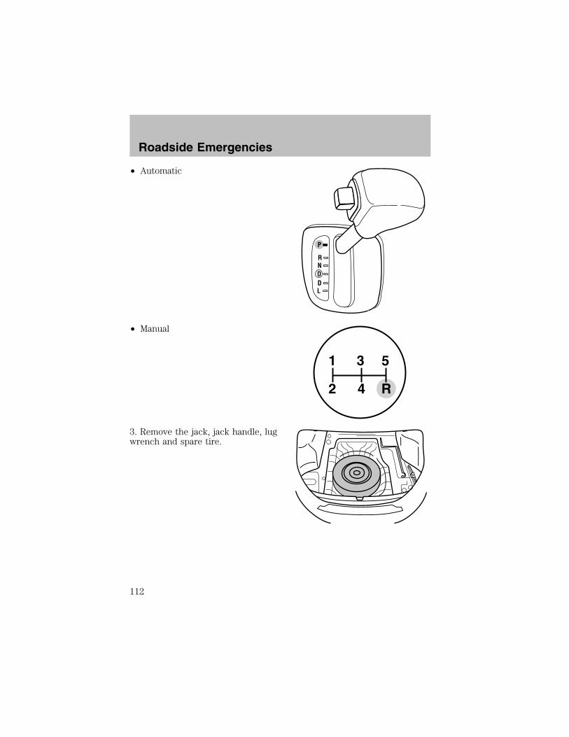
• Automatic
• Manual
3. Remove the jack, jack handle, lugwrench and spare tire.
P
RNDDL
1
2 4 R
3 5
Roadside Emergencies
112
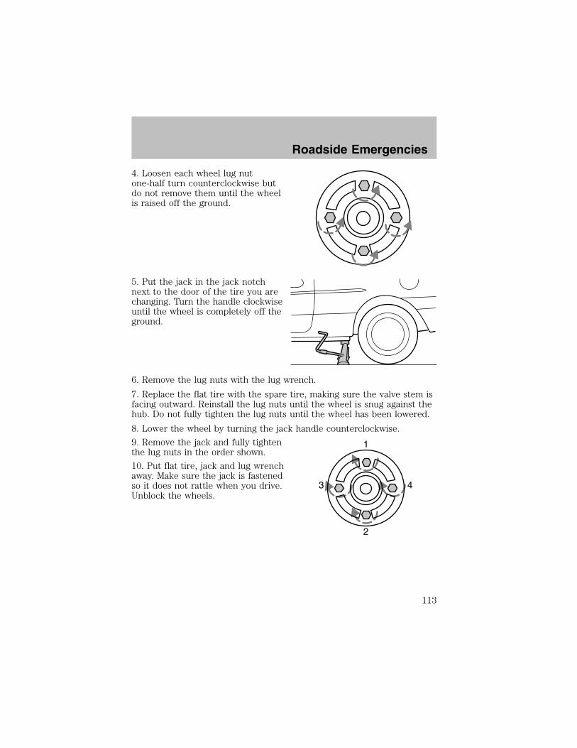
4. Loosen each wheel lug nutone-half turn counterclockwise butdo not remove them until the wheelis raised off the ground.
5. Put the jack in the jack notchnext to the door of the tire you arechanging. Turn the handle clockwiseuntil the wheel is completely off theground.
6. Remove the lug nuts with the lug wrench.
7. Replace the flat tire with the spare tire, making sure the valve stem isfacing outward. Reinstall the lug nuts until the wheel is snug against thehub. Do not fully tighten the lug nuts until the wheel has been lowered.
8. Lower the wheel by turning the jack handle counterclockwise.
9. Remove the jack and fully tightenthe lug nuts in the order shown.
10. Put flat tire, jack and lug wrenchaway. Make sure the jack is fastenedso it does not rattle when you drive.Unblock the wheels.
1
43
2
Roadside Emergencies
113

JUMP STARTING YOUR VEHICLE
The gases around the battery can explode if exposed to flames,sparks, or lit cigarettes. An explosion could result in injury or
vehicle damage.
Batteries contain sulfuric acid which can burn skin, eyes andclothing, if contacted.
Do not attempt to push-start your vehicle. Automatictransmissions do not have push-start capability; also, thecatalytic converter may become damaged.
Preparing your vehicle
When the battery is disconnected or a new battery is installed, thetransmission must relearn its shift strategy. As a result, the transmissionmay have firm and/or soft shifts. This operation is considered normal andwill not affect function or durability of the transmission. Over time, theadaptive learning process will fully update transmission operation.
1. Use only a 12–volt supply to start your vehicle.
2. Do not disconnect the battery of the disabled vehicle as this coulddamage the vehicle’s electrical system.
3. Park the booster vehicle close to the hood of the disabled vehiclemaking sure the two vehicles do not touch. Set the parking brake onboth vehicles and stay clear of the engine cooling fan and other movingparts.
4. Check all battery terminals and remove any excessive corrosion beforeyou attach the battery cables. Ensure that vent caps are tight and level.
5. Turn the heater fan on in both vehicles to protect any electricalsurges. Turn all other accessories off.
Roadside Emergencies
114
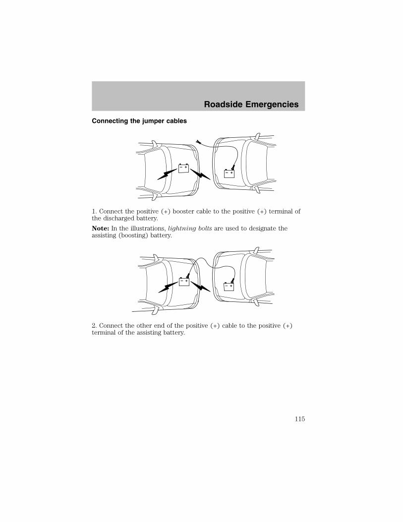
Connecting the jumper cables
1. Connect the positive (+) booster cable to the positive (+) terminal ofthe discharged battery.
Note: In the illustrations, lightning bolts are used to designate theassisting (boosting) battery.
2. Connect the other end of the positive (+) cable to the positive (+)terminal of the assisting battery.
+–
+–
+–
+–
Roadside Emergencies
115
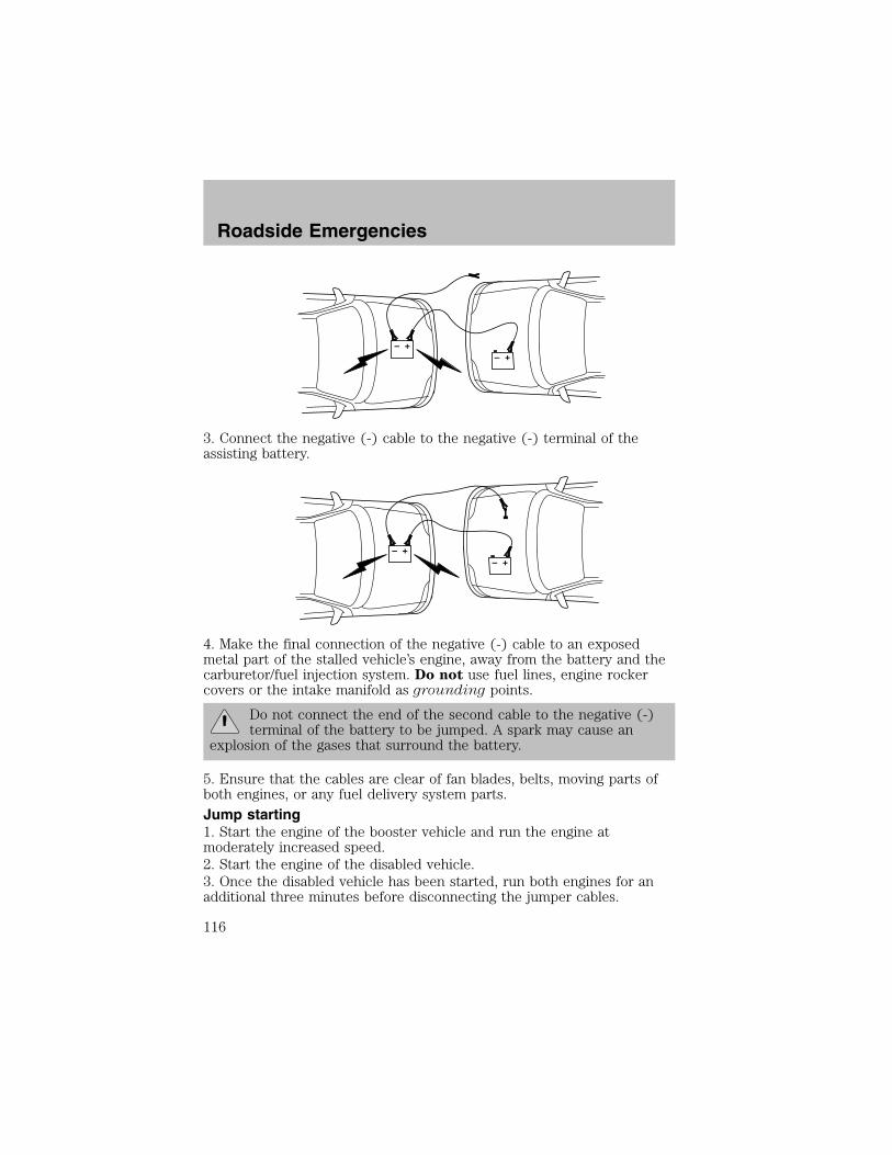
3. Connect the negative (-) cable to the negative (-) terminal of theassisting battery.
4. Make the final connection of the negative (-) cable to an exposedmetal part of the stalled vehicle’s engine, away from the battery and thecarburetor/fuel injection system. Do not use fuel lines, engine rockercovers or the intake manifold as grounding points.
Do not connect the end of the second cable to the negative (-)terminal of the battery to be jumped. A spark may cause an
explosion of the gases that surround the battery.
5. Ensure that the cables are clear of fan blades, belts, moving parts ofboth engines, or any fuel delivery system parts.
Jump starting1. Start the engine of the booster vehicle and run the engine atmoderately increased speed.2. Start the engine of the disabled vehicle.3. Once the disabled vehicle has been started, run both engines for anadditional three minutes before disconnecting the jumper cables.
+–
+–
+–
+–
Roadside Emergencies
116

Removing the jumper cables
Remove the jumper cables in the reverse order that they wereconnected.
1. Remove the jumper cable from the ground metal surface.
Note: In the illustrations, lightning bolts are used to designate theassisting (boosting) battery.
2. Remove the jumper cable on the negative (-) connection of thebooster vehicle’s battery.
+–
+–
+–
+–
Roadside Emergencies
117
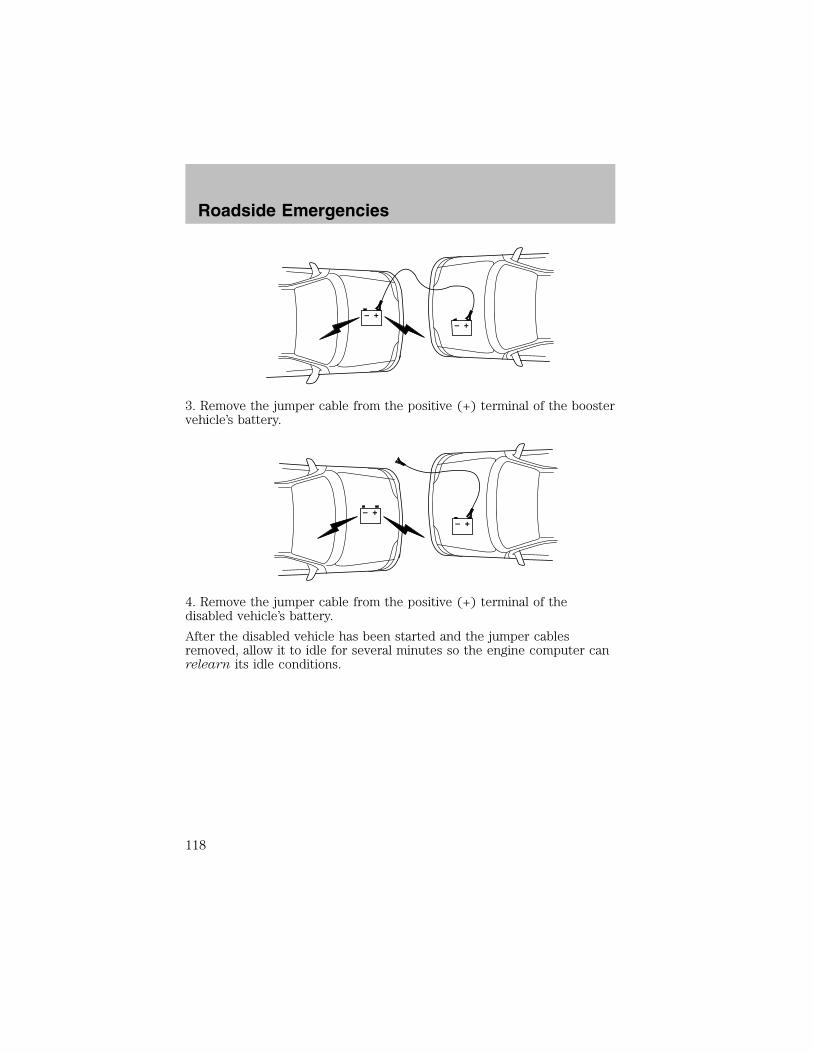
3. Remove the jumper cable from the positive (+) terminal of the boostervehicle’s battery.
4. Remove the jumper cable from the positive (+) terminal of thedisabled vehicle’s battery.
After the disabled vehicle has been started and the jumper cablesremoved, allow it to idle for several minutes so the engine computer canrelearn its idle conditions.
+–
+–
+–
+–
Roadside Emergencies
118
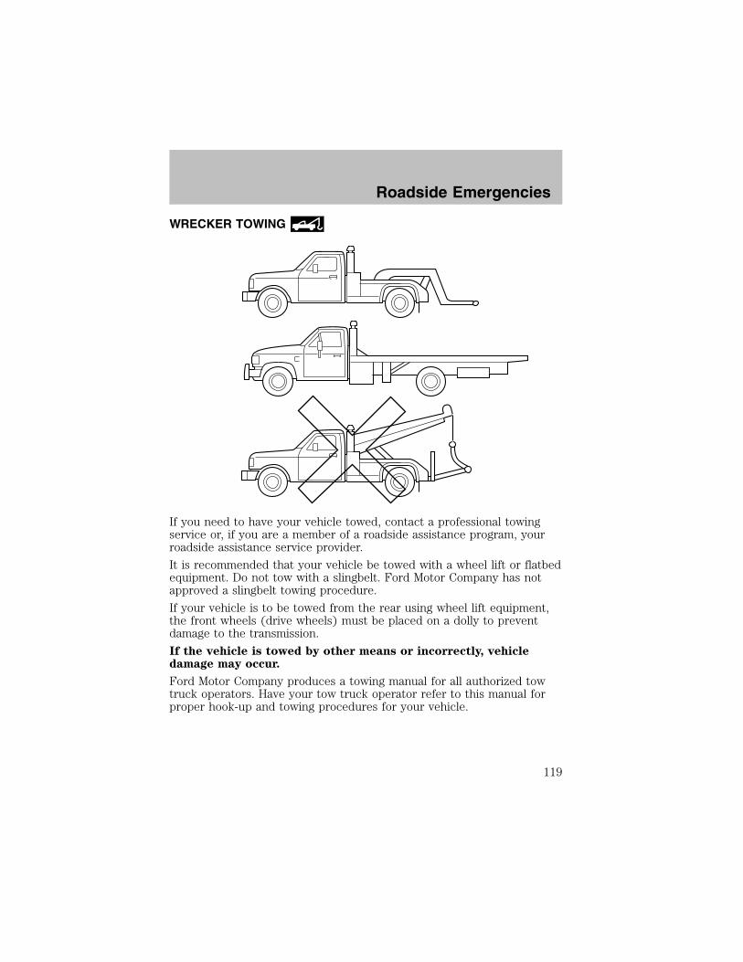
WRECKER TOWING
If you need to have your vehicle towed, contact a professional towingservice or, if you are a member of a roadside assistance program, yourroadside assistance service provider.
It is recommended that your vehicle be towed with a wheel lift or flatbedequipment. Do not tow with a slingbelt. Ford Motor Company has notapproved a slingbelt towing procedure.
If your vehicle is to be towed from the rear using wheel lift equipment,the front wheels (drive wheels) must be placed on a dolly to preventdamage to the transmission.
If the vehicle is towed by other means or incorrectly, vehicledamage may occur.
Ford Motor Company produces a towing manual for all authorized towtruck operators. Have your tow truck operator refer to this manual forproper hook-up and towing procedures for your vehicle.
Roadside Emergencies
119

FORD EXTENDED SERVICE PLANYou can get more protection for your new car or light truck bypurchasing Ford Extended Service Plan (Ford ESP) coverage. Ford ESPis an optional service contract which is backed by Ford Motor Companyor Ford Motor Service Company (in the U.S.) and Ford of Canada (inCanada). It provides the following:
• Benefits during the warranty period depending on the plan youpurchase (such as: reimbursement for rentals; coverage for certainmaintenance and wear items).
• Protection against covered repair costs after your Bumper-to-BumperWarranty expires.
You may purchase Ford ESP from any participating Ford and LincolnMercury and Ford of Canada dealer. There are several plans available invarious time, distance and deductible combinations which can be tailoredto fit your own driving needs. Ford ESP also offers reimbursementbenefits for towing and rental coverage.
When you buy Ford ESP, you receive Peace-of-Mind protectionthroughout the United States and Canada, provided by a network ofmore than 5,000 participating Ford or Lincoln Mercury and Ford ofCanada dealers.
If you did not take advantage of the Ford Extended Service Plan at thetime of purchasing your vehicle, you may still be eligible. Since thisinformation is subject to change, please ask your dealer for completedetails about Ford Extended Service Plan coverage options, or visit theFord ESP website at www.ford-esp.com.
GETTING THE SERVICES YOU NEED
At homeFord Motor Company and Ford of Canada have authorized dealerships toservice your vehicle. It is preferred that you return to the authorizeddealer where your vehicle was purchased when warranty repairs areneeded. However, you may also take your vehicle to another Ford MotorCompany or Ford of Canada dealership authorized for warranty repairs.Certain warranty repairs require special training though, so not alldealers are authorized to perform all warranty repairs. That means thatdepending on the warranty repair needed, the vehicle may need to betaken to another dealer. If a particular dealership cannot assist you, thencontact the Customer Relationship Center.
Customer Assistance
120
If you have questions or concerns, or are unsatisfied with the service youare receiving, follow these steps:
1. Contact your Sales Representative or Service Advisor at yourselling/servicing dealership.
2. If your inquiry or concern remains unresolved, contact the SalesManager or Service Manager at the dealership.
3. If the inquiry or concern cannot be resolved at the dealership level,please contact the Ford Customer Relationship Center.
Away from homeIf you own a Ford or Mercury vehicle and are away from home whenyour vehicle needs service, or if you need more help than the dealershipcould provide, after following the steps described above, contact theFord Customer Relationship Center to find an authorized dealership tohelp you.
In the United States:
Ford Motor CompanyCustomer Relationship Center16800 Executive Plaza DriveP.O. Box 6248Dearborn, Michigan 481211-800-392-3673 (FORD)(TDD for the hearing impaired: 1-800-232-5952)www.ford.com
In Canada:Customer Relationship CentreFord Motor Company of Canada, LimitedP.O. Box 2000Oakville, Ontario L6J 5E41-800-565-3673 (FORD)www.ford.ca
If you own a Lincoln vehicle and are away from home when your vehicleneeds service, or if you need more help than the dealership couldprovide, after following the steps described above, contact the FordCustomer Relationship Center to find an authorized dealership to helpyou.
Customer Assistance
121
In the United States:Ford Motor CompanyCustomer Relationship Center16800 Executive Plaza DriveP.O. Box 6248Dearborn, Michigan 481211-800-521-4140(TDD for the hearing impaired: 1-800-232-5952)www.ford.com
In Canada:Customer Relationship CentreFord Motor Company of Canada, LimitedP.O. Box 2000Oakville, Ontario L6J 5E41-800-565-3673 (FORD)www.ford.ca
In order to help you service your Ford or Lincoln Mercury vehicle, pleasehave the following information available when contacting a CustomerRelationship Center:
• Your telephone number (home and business)
• The name of the dealer and the city where the dealership is located
• The year and make of your vehicle
• The date of vehicle purchase
• The current odometer reading
• The vehicle identification number (VIN)
If you still have a complaint involving a warranty dispute, you may wishto contact the Dispute Settlement Board (U.S.).
In some states (in the U.S.) you must directly notify Ford in writingbefore pursuing remedies under your state’s warranty laws. Ford is alsoallowed a final repair attempt in some states.
In the United States, a warranty dispute must be submitted to theDispute Settlement Board before taking action under the Magnuson-MossWarranty Act, or to the extent allowed by state law, before pursuingreplacement or repurchase remedies provided by certain state laws. Thisdispute handling procedure is not required prior to enforcing statecreated rights or other rights which are independent of theMagnuson-Moss Warranty Act or state replacement or repurchase laws.
Customer Assistance
122
THE DISPUTE SETTLEMENT BOARD (U.S. ONLY)
The Dispute Settlement Board is:
• an independent, third-party arbitration program for warranty disputes.
• available free to owners and lessees of qualifying Ford Motor Companyvehicles.
The Dispute Settlement Board may not be available in all states. FordMotor Company reserves the right to change eligibility limitations, modifyprocedures and/or to discontinue this service without notice and withoutincurring obligations per applicable state law.
What kinds of cases does the Board review?Unresolved warranty repair concerns or vehicle performance concerns ason Ford and Lincoln Mercury cars and Ford and Lincoln Mercury lighttrucks which are within the terms of any applicable written new vehiclewarranty are eligible for review, except those involving:
• a non-Ford product
• a non-Ford dealership
• sales disputes between customer and dealer except those associatedwith warranty repairs or concerns with the vehicle’s performance asdesigned
• a request for reimbursement of consequential expenses unless aservice or product concern is being reviewed
• items not covered by the New Vehicle Limited Warranty (includingmaintenance and wear items)
• alleged personal injury/property damage claims
• cases currently in litigation
• vehicles not used primarily for family, personal or household purposes(except in states where the Dispute Settlement Board is required toreview commercial vehicles)
• vehicles with non-U.S. warranties
Concerns are ineligible for review if the New Vehicle Limited Warrantyhas expired at receipt of your application and, in certain states eligibilityis dependent upon the customer’s possession of the vehicle.
Eligibility may differ according to state law. For example, see the uniquebrochures for California, West Virginia, Georgia and Wisconsinpurchasers/lessees.
Customer Assistance
123

Board membershipThe Board consists of:• Three consumer representatives• A Ford or Lincoln Mercury dealership representativeConsumer candidates for Board membership are recruited and trained byan independent consulting firm. The dealership Board member is chosenfrom Ford and Lincoln Mercury dealership management, recognized fortheir business leadership qualities.
What the Board needsTo have your case reviewed you must complete the application in theDSB brochure and mail it to the address provided on the applicationform. Some states will require you to use certified mail, with returnreceipt requested.
Your application is reviewed and, if it is determined to be eligible, youwill receive an acknowledgment indicating:
• The file number assigned to your application.
• The toll-free phone number of the DSB’s independent administrator.
Your dealership and a Ford Motor Company representative will then beasked to submit statements.
To properly review your case, the Board needs the following information:
• Legible copies of all documents and maintenance or repair ordersrelevant to the case.
• The year, make, model, and Vehicle Identification Number (VIN) listedon your vehicle ownership license.
• The date of repair(s) and mileage at the time of occurrence(s).
• The current mileage.
• The name of the dealer(s) who sold or serviced the vehicle.
• A brief description of your unresolved concern.
• A brief summary of the action taken by the dealer(s) and Ford MotorCompany.
• The names (if known) of all the people you contacted at thedealership(s).
• A description of the action you expect to resolve your concern.
You will receive a letter of explanation if your application does notqualify for Board review.
Customer Assistance
124
Oral presentationsIf you would like to make an oral presentation, indicate YES to question6 on the application. While it is your right to make an oral presentationbefore the Board, this is not a requirement and the Board will decide thecase whether or not an oral presentation is made. An oral presentationmay be requested by the Board as well.
Making a decisionBoard members review all available information related to eachcomplaint, including oral presentations, and arrive at a fair and impartialdecision. Board review may be terminated at any time by either party.
Every effort is made to decide the case within 40 days of the date thatall requested information is received by the Board. Since the Boardgenerally meets once a month, it may take longer for the Board toconsider some cases.
After a case is reviewed, the Board mails you a decision letter and aform on which to accept or reject the Board’s decision. The decisions ofthe Board are binding on Ford (and, in some cases, on the dealer) butnot on consumers who are free to pursue other remedies available tothem under state or federal law.
To request a DSB Brochure/ApplicationFor a brochure/application, speak to your dealer or write/call to theBoard at the following address/phone number:
Dispute Settlement BoardP.O. Box 5120Southfield, MI 48086–51201–800–428–3718
You may also contact the North American Customer Relationship Centerat 1-800-392-3673 (Ford), TDD for the hearing impaired: 1-800-232-5952or by writing to the Center at the following address:
Ford Motor CompanyCustomer Relationship Center16800 Executive Plaza DriveP.O. Box 6248Dearborn, Michigan 48121
Customer Assistance
125

UTILIZING THE MEDIATION/ARBITRATION PROGRAM (CANADAONLY)In those cases where you continue to feel that the efforts by Ford andthe dealer to resolve a factory-related vehicle service concern have beenunsatisfactory, Ford of Canada participates in an impartial third partymediation/arbitration program administered by the Canadian MotorVehicle Arbitration Plan (CAMVAP).
The CAMVAP program is a straight-forward and relatively speedyalternative to resolve a disagreement when all other efforts to produce asettlement have failed. This procedure is without cost to you and isdesigned to eliminate the need for lengthy and expensive legalproceedings.
In the CAMVAP program, impartial third-party arbitrators conducthearings at mutually convenient times and places in an informalenvironment. These impartial arbitrators review the positions of theparties, make decisions and, when appropriate, render awards to resolvedisputes. CAMVAP decisions are fast, fair, and final; the arbitrator’saward is binding both to you and Ford of Canada.
CAMVAP services are available in all territories and provinces. For moreinformation, without charge or obligation, call your CAMVAP ProvincialAdministrator directly at 1-800-207-0685.
GETTING ASSISTANCE OUTSIDE THE U.S. AND CANADABefore exporting your vehicle to a foreign country, contact theappropriate foreign embassy or consulate. These officials can inform youof local vehicle registration regulations and where to find unleaded fuel.
If you cannot find unleaded fuel or can only get fuel with an anti-knockindex lower than is recommended for your vehicle, contact a district orowner relations/customer relationship office.
The use of leaded fuel in your vehicle without proper conversion maydamage the effectiveness of your emission control system and may causeengine knocking or serious engine damage. Ford Motor Company/Ford ofCanada is not responsible for any damage caused by use of improperfuel.
In the United States, using leaded fuel may also result in difficultyimporting your vehicle back into the U.S.
Customer Assistance
126
If your vehicle must be serviced while you are traveling or living inCentral or South America, the Caribbean, or the Middle East, contact thenearest Ford dealership. If the dealership cannot help you, write or call:
FORD MOTOR COMPANYWORLDWIDE DIRECT MARKET OPERATIONS1555 Fairlane DriveFairlane Business Park #3Allen Park, Michigan 48101U.S.A.Telephone: (313) 594-4857FAX: (313) 390-0804
If you are in another foreign country, contact the nearest Forddealership. If the dealership employees cannot help you, they can directyou to the nearest Ford affiliate office.
If you buy your vehicle in North America and then relocate outside ofthe U.S. or Canada, register your vehicle identification number (VIN) andnew address with Ford Motor Company Worldwide Direct MarketOperations.
ORDERING ADDITIONAL OWNER’S LITERATURETo order the publications in this portfolio, contact Helm, Incorporated at:
HELM, INCORPORATEDP.O. Box 07150Detroit, Michigan 48207
Or call:
For a free publication catalog, order toll free: 1-800-782-4356
Monday-Friday 8:00 a.m. - 6:00 p.m. EST
Helm, Incorporated can also be reached by their website:www.helminc.com.
(Items in this catalog may be purchased by credit card, check ormoney order.)
Obtaining a French owner’s guideFrench Owner’s Guides can be obtained from your dealer or by writing toFord Motor Company of Canada, Limited, Service Publications, P.O. Box1580, Station B, Mississauga, Ontario L4Y 4G3.
Customer Assistance
127
IN CALIFORNIA (U.S. ONLY)California Civil Code Section 1793.2(d) requires that, if a manufactureror its representative is unable to repair a motor vehicle to conform to thevehicle’s applicable express warranty after a reasonable number ofattempts, the manufacturer shall be required to either replace thevehicle with one substantially identical or repurchase the vehicle andreimburse the buyer in an amount equal to the actual price paid orpayable by the consumer (less a reasonable allowance for consumeruse). The consumer has the right to choose whether to receive a refundor replacement vehicle.
California Civil Code Section 1793.22(b) presumes that the manufacturerhas had a reasonable number of attempts to conform the vehicle to itsapplicable express warranties if, within the first 18 months of ownershipof a new vehicle or the first 29,000 km (18,000 miles), whichever occursfirst:
1. Two or more repair attempts are made on the same nonconformitylikely to cause death or serious bodily injury OR
2. Four or more repair attempts are made on the same nonconformity (adefect or condition that substantially impairs the use, value or safety ofthe vehicle) OR
3. The vehicle is out of service for repair of nonconformities for a total ofmore than 30 calendar days (not necessarily all at one time)
In the case of 1 or 2 above, the consumer must also notify themanufacturer of the need for the repair of the nonconformity at thefollowing address:
Ford Motor Company16800 Executive Plaza DriveMail Drop 3NE-BDearborn, MI 48126
Customer Assistance
128
REPORTING SAFETY DEFECTS (U.S. ONLY)If you believe that your vehicle hasa defect which could cause a crashor could cause injury or death, youshould immediately inform the National Highway Traffic SafetyAdministration (NHTSA) in addition to notifying Ford Motor Company.
If NHTSA receives similar complaints, it may open an investigation, andif it finds that a safety defect exists in a group of vehicles, it may order arecall and remedy campaign. However, NHTSA cannot become involvedin individual problems between you, your dealer, or Ford MotorCompany.
To contact NHTSA, you may either call the Auto Safety Hotline toll-freeat 1–800–424–9393 (or 366–0123 in the Washington D.C. area) or writeto:
NHTSAU.S. Department of TransportationWashington, D.C. 20590
You can also obtain other information about motor vehicle safety fromthe Hotline.
Customer Assistance
129
WASHING THE EXTERIORWash your vehicle regularly with cool or lukewarm water and a neutralPh shampoo, such as Motorcraft Detail Wash (ZC-3–A), which is availablefrom your dealer.
• Never use strong household detergents or soap, such as dish washingor laundry liquid. These products can discolor and spot paintedsurfaces.
• Never wash a vehicle that is “hot to the touch” or during exposure tostrong, direct sunlight.
• Always use a clean sponge or carwash mitt with plenty of water forbest results.
• Dry the vehicle with a chamois or soft terry cloth towel in order toeliminate water spotting.
• It is especially important to wash the vehicle regularly during thewinter months, as dirt and road salt are difficult to remove and causedamage to the vehicle.
• Immediately remove items such as gasoline, diesel fuel, bird droppingsand insect deposits because they can cause damage to the vehicle’spaintwork and trim over time.
• Remove any exterior accessories, such as antennas, before entering acar wash.
• Suntan lotions and insect repellents can damage any paintedsurface; if these substances come in contact with your vehicle,wash off as soon as possible.
WAXINGApplying a polymer paint sealant to your vehicle every six months willassist in reducing minor scratches and paint damage.
• Wash the vehicle first.
• Do not use waxes that contain abrasives.
• Do not allow paint sealant to come in contact with any non-body(low-gloss black) colored trim, such as grained door handles, roofracks, bumpers, side moldings, mirror housings or the windshield cowlarea. The paint sealant will “gray” or stain the parts over time.
Cleaning
130
PAINT CHIPS
Your dealer has touch-up paint and sprays to match your vehicle’s color.Take your color code (printed on a sticker in the driver’s door jam) toyour dealer to ensure you get the correct color.
• Remove particles such as bird droppings, tree sap, insect deposits, tarspots, road salt and industrial fallout before repairing paint chips.
• Always read the instructions before using the products.
ALUMINUM WHEELS AND WHEEL COVERS
Aluminum wheels and wheel covers are coated with a clearcoat paintfinish. In order to maintain their shine:
• Clean weekly with Motorcraft Wheel and Tire Cleaner (ZC-37–A),which is available from your dealer. Heavy dirt and brake dustaccumulation may require agitation with a sponge. Rinse thoroughlywith a strong stream of water.
• Never apply any cleaning chemical to hot or warm wheel rims orcovers.
• Some automatic car washes may cause damage to the finish on yourwheel rims or covers. Chemical-strength cleaners, or cleaningchemicals, in combination with brush agitation to remove brake dustand dirt, could wear away the clearcoat finish over time.
• Do not use hydrofluoric acid-based or high caustic-based wheelcleaners, steel wool, fuels or strong household detergent.
• To remove tar and grease, use Ford Extra Strength Tar and Road OilRemoval (B7A-19520–AA), available from your dealer.
ENGINEEngines are more efficient when they are clean because grease and dirtbuildup keep the engine warmer than normal. When washing:
• Take care when using a power washer to clean the engine. Thehigh-pressure fluid could penetrate the sealed parts and causedamage.
• Do not spray a hot engine with cold water to avoid cracking theengine block or other engine components.
• Spray Motorcraft Engine Shampoo and Degreaser (ZC-20) on all partsthat require cleaning and pressure rinse clean.
Cleaning
131
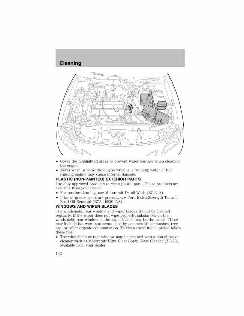
• Cover the highlighted areas to prevent water damage when cleaningthe engine.
• Never wash or rinse the engine while it is running; water in therunning engine may cause internal damage.
PLASTIC (NON-PAINTED) EXTERIOR PARTSUse only approved products to clean plastic parts. These products areavailable from your dealer.• For routine cleaning, use Motorcraft Detail Wash (ZC-3–A).• If tar or grease spots are present, use Ford Extra Strength Tar andRoad Oil Removal (B7A-19520–AA).
WINDOWS AND WIPER BLADESThe windshield, rear window and wiper blades should be cleanedregularly. If the wiper does not wipe properly, substances on thewindshield, rear window or the wiper blades may be the cause. Thesemay include hot wax treatments used by commercial car washes, treesap, or other organic contamination. To clean these items, please followthese tips:• The windshield or rear window may be cleaned with a non-abrasivecleaner such as Motorcraft Ultra Clear Spray Glass Cleaner (ZC-23),available from your dealer.
Cleaning
132
• Do not use abrasives, as they may cause scratches.
• Do not use fuel, kerosene, or paint thinner to clean any parts.
• Wiper blades can be cleaned with isopropyl (rubbing) alcohol orwindshield washer solution. Be sure to replace wiper blades when theyappear worn or do not function properly.
INSTRUMENT PANEL AND CLUSTER LENSClean the instrument panel with a damp cloth, then dry with a dry cloth.
• Avoid cleaners or polish that increase the gloss of the upper portion ofthe instrument panel. The dull finish in this area helps protect thedriver from undesirable windshield reflection.
Do not use chemical solvents or strong detergents when cleaningthe steering wheel or instrument panel to avoid contamination of
the air bag system.
• Be certain to wash or wipe your hands clean if you have been incontact with certain products such as insect repellent and suntanlotion in order to avoid possible damage to the painted surfaces.
INTERIORFor fabric, carpets, cloth seats and safety belts:
• Remove dust and loose dirt with a vacuum cleaner.
• Remove light stains and soil with Ford Extra Strength UpholsteryCleaner (E8AZ-19523–AA).
• If grease or tar is present on the material, spot-clean the area firstwith Motorcraft Spot and Stain Remover (ZC-14).
• Never saturate the seat covers with cleaning solution.
• Do not use household cleaning products or glass cleaners, which canstain and discolor the fabric and affect the flame retardant abilities ofthe seat materials.
Do not use cleaning solvents, bleach or dye on the vehicle’sseatbelts, as these actions may weaken the belt webbing.
Cleaning
133

LEATHER SEATS (IF EQUIPPED)Your leather seating surfaces have a clear, protective coating over theleather.• To clean, use a soft cloth with Motorcraft Deluxe Leather and VinylCleaner (ZC-11–A). Dry the area with a soft cloth.
• To help maintain its resiliency and color, use the Motorcraft DeluxeLeather Care Kit (ZC-11–D), available from your authorized dealer.
• Do not use household cleaning products, alcohol solutions, solvents orcleaners intended for rubber, vinyl and plastics, or oil/petroleum-basedleather conditioners. These products may cause premature wearing ofthe clear, protective coating.
UNDERBODYFlush the complete underside of your vehicle frequently. Keep body anddoor drain holes free from packed dirt.
FORD, LINCOLN AND MERCURY CAR CARE PRODUCTSYour Ford, Lincoln or Mercury dealer has many quality products availableto clean your vehicle and protect its finishes. These quality productshave been specifically engineered to fulfill your automotive needs; theyare custom designed to complement the style and appearance of yourvehicle. Each product is made from high quality materials that meet orexceed rigid specifications. For best results, use the following productsor products of equivalent quality:
Motorcraft Custom Clearcoat Polish (ZC–8–A)
Ford Custom Vinyl Protectant* (not available in Canada)(F2AZ—19530–A)
Motorcraft Vinyl Cleaner (Canada only) (CXC-93)
Motorcraft Vinyl Conditioner (Canada only) (CXC-94)
Motorcraft Deluxe Leather and Vinyl Cleaner (not available in Canada)(ZC-11–A)
Ford Extra Strength Tar and Road Oil Remover* (not available inCanada) (B7A-19520–AA)
Ford Extra Strength Upholstery Cleaner (not available in Canada)(E8AZ-19523–AA)
Motorcraft Custom Bright Metal Cleaner (ZC-15)
Motorcraft Wheel and Tire Cleaner (ZC-37–A)
Cleaning
134

Motorcraft Dash and Vinyl Cleaner (ZC-38–A)
Motorcraft Car Care Kit (ZC-26)
Ford Premium Car Wash Concentrate (F2SZ-19523–WC)
Motorcraft Carlite Glass Cleaner (Canada only) (CXC-100)
Motorcraft Spot and Stain Remover (ZC-14)
Motorcraft Detail Wash (ZC-3–A)
Motorcraft Tire Detailer (ZC-28)
Motorcraft Triple Clean (ZC-13)
Motorcraft Ultra-Clear Spray Glass Cleaner (not available in Canada)(ZC-23)
Motorcraft Engine Shampoo and Degreaser (ZC-20)
* May be sold with the Motorcraft name
Cleaning
135

SERVICE RECOMMENDATIONS
To help you service your vehicle:
• We highlight do-it-yourself items in the engine compartment for easylocation.
• We provide a scheduled maintenance guide which makes trackingroutine service easy.
If your vehicle requires professional service, your dealership can providethe necessary parts and service. Check your Warranty Guide/OwnerInformation Guide to find out which parts and services are covered.
Use only recommended fuels, lubricants, fluids and service partsconforming to specifications. Motorcraft parts are designed and built toprovide the best performance in your vehicle.
PRECAUTIONS WHEN SERVICING YOUR VEHICLE
• Do not work on a hot engine.
• Make sure that nothing gets caught in moving parts.
• Do not work on a vehicle with the engine running in an enclosedspace, unless you are sure you have enough ventilation.
• Keep all open flames and other burning (cigarettes) material awayfrom the battery and all fuel related parts.
2. Turn off the engine and removethe key.
3. Block the wheels to prevent thevehicle from moving unexpectedly.
• Manual transaxle:
P
RNDDL
Maintenance and Specifications
136

1. Set the parking brake, depressthe clutch and place the gearshift in1 (First).
2. Turn off the engine and removethe key.
3. Block the wheels to prevent thevehicle from moving unexpectedly.
Working with the engine off• Automatic transaxle:
1. Set the parking brake and shift to P (Park).
2. Turn off the engine and remove the key.
3. Block the wheels.
• Manual transaxle:
1. Set the parking brake, depress the clutch and place the gearshift in 1(First).
2. Turn off the engine and remove the key.
3. Block the wheels.
1
2 4 R
3 5
Maintenance and Specifications
137
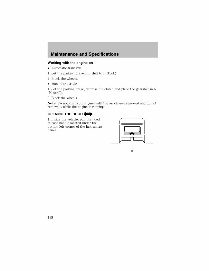
Working with the engine on
• Automatic transaxle:
1. Set the parking brake and shift to P (Park).
2. Block the wheels.
• Manual transaxle
1. Set the parking brake, depress the clutch and place the gearshift in N(Neutral).
2. Block the wheels.
Note: Do not start your engine with the air cleaner removed and do notremove it while the engine is running.
OPENING THE HOOD
1. Inside the vehicle, pull the hoodrelease handle located under thebottom left corner of the instrumentpanel.
Maintenance and Specifications
138
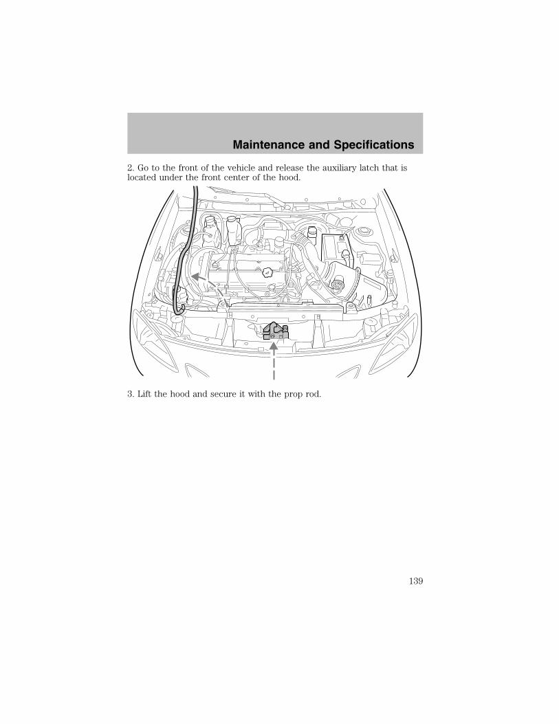
2. Go to the front of the vehicle and release the auxiliary latch that islocated under the front center of the hood.
3. Lift the hood and secure it with the prop rod.
Maintenance and Specifications
139

IDENTIFYING COMPONENTS IN THE ENGINE COMPARTMENT
2.0L DOHC Zetec engine
1. Transmission fluid dipstick (automatic transaxle)
2. Battery
3. Air filter assembly
4. Engine oil filler cap
5. Engine oil dipstick
6. Power steering fluid reservoir
7. Engine coolant reservoir
8. Windshield washer fluid reservoir
9. Brake fluid reservoir
987 1 23
46
5
Maintenance and Specifications
140
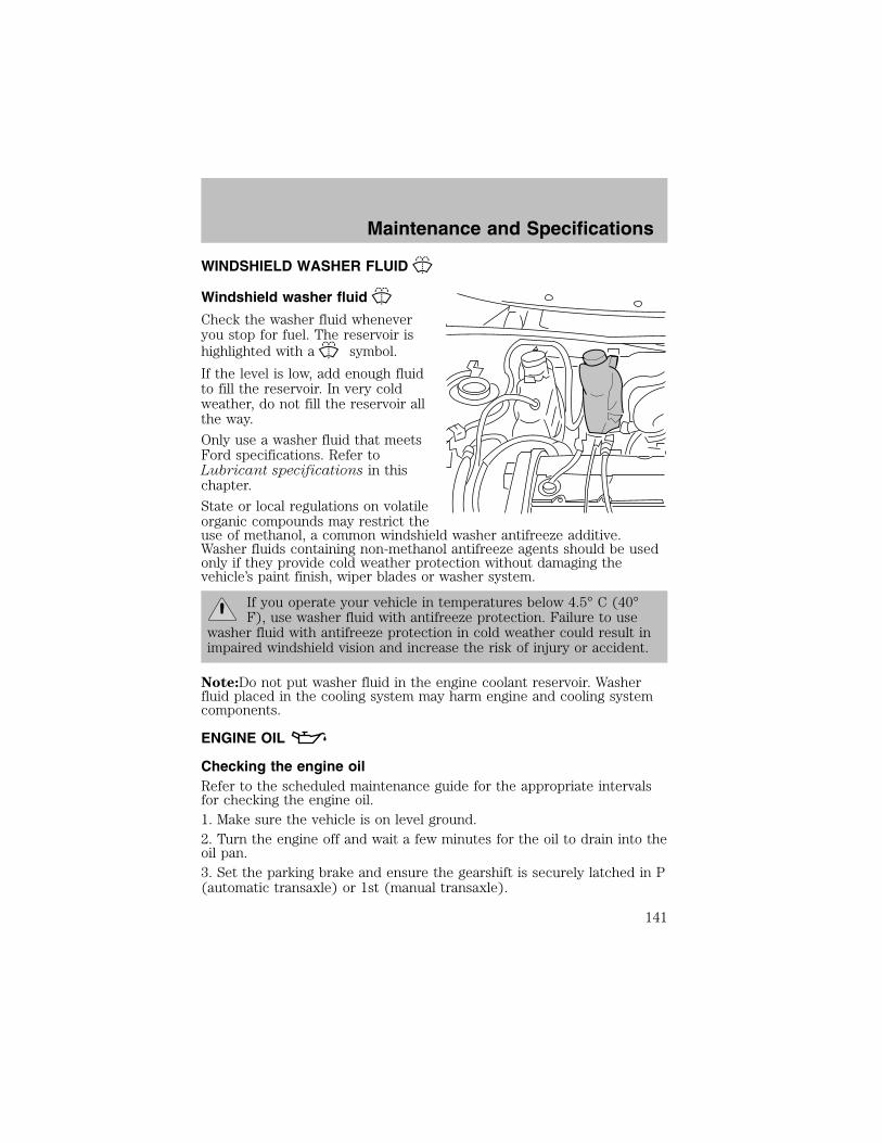
WINDSHIELD WASHER FLUID
Windshield washer fluid
Check the washer fluid wheneveryou stop for fuel. The reservoir ishighlighted with a symbol.
If the level is low, add enough fluidto fill the reservoir. In very coldweather, do not fill the reservoir allthe way.
Only use a washer fluid that meetsFord specifications. Refer toLubricant specifications in thischapter.
State or local regulations on volatileorganic compounds may restrict theuse of methanol, a common windshield washer antifreeze additive.Washer fluids containing non-methanol antifreeze agents should be usedonly if they provide cold weather protection without damaging thevehicle’s paint finish, wiper blades or washer system.
If you operate your vehicle in temperatures below 4.5° C (40°F), use washer fluid with antifreeze protection. Failure to use
washer fluid with antifreeze protection in cold weather could result inimpaired windshield vision and increase the risk of injury or accident.
Note:Do not put washer fluid in the engine coolant reservoir. Washerfluid placed in the cooling system may harm engine and cooling systemcomponents.
ENGINE OIL
Checking the engine oilRefer to the scheduled maintenance guide for the appropriate intervalsfor checking the engine oil.1. Make sure the vehicle is on level ground.2. Turn the engine off and wait a few minutes for the oil to drain into theoil pan.3. Set the parking brake and ensure the gearshift is securely latched in P(automatic transaxle) or 1st (manual transaxle).
Maintenance and Specifications
141
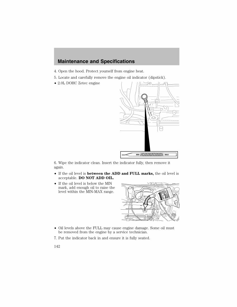
4. Open the hood. Protect yourself from engine heat.
5. Locate and carefully remove the engine oil indicator (dipstick).
• 2.0L DOHC Zetec engine
6. Wipe the indicator clean. Insert the indicator fully, then remove itagain.
• If the oil level is between the ADD and FULL marks, the oil level isacceptable. DO NOT ADD OIL.
• If the oil level is below the MINmark, add enough oil to raise thelevel within the MIN-MAX range.
• Oil levels above the FULL may cause engine damage. Some oil mustbe removed from the engine by a service technician.
7. Put the indicator back in and ensure it is fully seated.
MAXMIN
Maintenance and Specifications
142

Adding engine oil1. Check the engine oil. For instructions, refer to Checking the engineoil in this chapter.2. If the engine oil level is not within the normal range, add only certifiedengine oil of the recommended viscosity. Remove the engine oil filler capand use a funnel to pour the engine oil into the opening.3. Recheck the engine oil level. Make sure the oil level is not above theMAX mark on the engine oil level indicator (dipstick).4. Install the indicator and ensure it is fully seated.5. Fully install the engine oil filler cap by turning the filler cap clockwise1/4 of a turn until three clicks are heard or until the cap is fully seated.To avoid possible oil loss, DO NOT operate the vehicle with theengine oil level indicator and/or the engine oil filler cap removed.
Engine oil and filter recommendationsLook for this certificationtrademark.
SAE 5W-20 engine oil is recommended.Only use oils “Certified For Gasoline Engines” by the AmericanPetroleum Institute (API). Use Motorcraft or an equivalent oil meetingFord specification WSS-M2C153–H. SAE 5W-20 oil provides optimumfuel economy and durability performance meeting allrequirements for your vehicle’s engine.
Do not use supplemental engine oil additives, oil treatments or enginetreatments. They are unnecessary and could, under certain conditions,lead to engine damage which is not covered by your warranty.
Change your engine oil and filter according to the appropriate schedulelisted in the scheduled maintenance guide.
Ford production and aftermarket (Motorcraft) oil filters are designed foradded engine protection and long life. If a replacement oil filter is used
Maintenance and Specifications
143
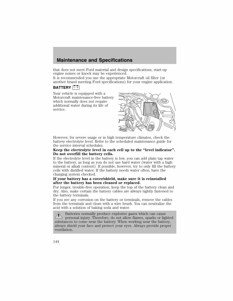
that does not meet Ford material and design specifications, start-upengine noises or knock may be experienced.It is recommended you use the appropriate Motorcraft oil filter (oranother brand meeting Ford specifications) for your engine application.
BATTERY
Your vehicle is equipped with aMotorcraft maintenance-free batterywhich normally does not requireadditional water during its life ofservice.
However, for severe usage or in high temperature climates, check thebattery electrolyte level. Refer to the scheduled maintenance guide forthe service interval schedules.Keep the electrolyte level in each cell up to the “level indicator”.Do not overfill the battery cells.
If the electrolyte level in the battery is low, you can add plain tap waterto the battery, as long as you do not use hard water (water with a highmineral or alkali content). If possible, however, try to only fill the batterycells with distilled water. If the battery needs water often, have thecharging system checked.If your battery has a cover/shield, make sure it is reinstalledafter the battery has been cleaned or replaced.
For longer, trouble-free operation, keep the top of the battery clean anddry. Also, make certain the battery cables are always tightly fastened tothe battery terminals.If you see any corrosion on the battery or terminals, remove the cablesfrom the terminals and clean with a wire brush. You can neutralize theacid with a solution of baking soda and water.
Batteries normally produce explosive gases which can causepersonal injury. Therefore, do not allow flames, sparks or lighted
substances to come near the battery. When working near the battery,always shield your face and protect your eyes. Always provide properventilation.
Maintenance and Specifications
144
When lifting a plastic-cased battery, excessive pressure on theend walls could cause acid to flow through the vent caps,
resulting in personal injury and/or damage to the vehicle or battery.Lift the battery with a battery carrier or with your hands on oppositecorners.
Keep batteries out of reach of children. Batteries contain sulfuricacid. Avoid contact with skin, eyes or clothing. Shield your eyes
when working near the battery to protect against possible splashing ofacid solution. In case of acid contact with skin or eyes, flushimmediately with water for a minimum of 15 minutes and get promptmedical attention. If acid is swallowed, call a physician immediately.
Battery posts, terminals and related accessories contain lead andlead compounds. Wash hands after handling.
Because your vehicle’s engine is electronically controlled by a computer,some control conditions are maintained by power from the battery. Whenthe battery is disconnected or a new battery is installed, the engine mustrelearn its idle and fuel trim strategy for optimum driveability andperformance. To begin this process:1. With the vehicle at a complete stop, set the parking brake.
2. Put the gearshift in P (Park) (automatic transaxle) or the neutralposition (manual transaxle), turn off all accessories and start the engine.
3. Run the engine until it reaches normal operating temperature.
4. Allow the engine to idle for at least one minute.
5. Turn the A/C on and allow the engine to idle for at least one minute.
6. Drive the vehicle to complete the relearning process.
• The vehicle may need to be driven 16 km (10 miles) or more torelearn the idle and fuel trim strategy.
• If you do not allow the engine to relearn its idle trim, the idlequality of your vehicle may be adversely affected until the idletrim is eventually relearned.
When the battery is disconnected or a new battery installed, thetransmission must learn its adaptive strategy. As a result of this, thetransmission may shift firmly. This operation is considered normal andwill fully update transmission operation to its optimum shift feel.
Maintenance and Specifications
145
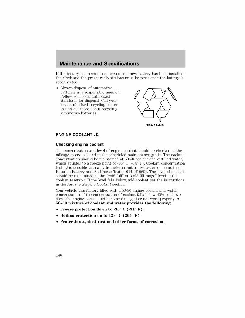
If the battery has been disconnected or a new battery has been installed,the clock and the preset radio stations must be reset once the battery isreconnected.
• Always dispose of automotivebatteries in a responsible manner.Follow your local authorizedstandards for disposal. Call yourlocal authorized recycling centerto find out more about recyclingautomotive batteries.
ENGINE COOLANT
Checking engine coolant
The concentration and level of engine coolant should be checked at themileage intervals listed in the scheduled maintenance guide. The coolantconcentration should be maintained at 50/50 coolant and distilled water,which equates to a freeze point of -36° C (-34° F). Coolant concentrationtesting is possible with a hydrometer or antifreeze tester (such as theRotunda Battery and Antifreeze Tester, 014–R1060). The level of coolantshould be maintained at the “cold full” of “cold fill range” level in thecoolant reservoir. If the level falls below, add coolant per the instructionsin the Adding Engine Coolant section.
Your vehicle was factory-filled with a 50/50 engine coolant and waterconcentration. If the concentration of coolant falls below 40% or above60%, the engine parts could become damaged or not work properly. A50–50 mixture of coolant and water provides the following:
• Freeze protection down to -36° C (-34° F).
• Boiling protection up to 129° C (265° F).
• Protection against rust and other forms of corrosion.
LE
AD
RE
TU
RN
RECYCLE
Maintenance and Specifications
146

• Enables calibrated gauges towork properly.
When the engine is cold, check thelevel of the engine coolant in thereservoir.
• The engine coolant should be atthe “cold fill level” or within the“cold fill range” as listed on theengine coolant reservoir(depending upon application).
• Refer to the ScheduledMaintenance Guide for serviceinterval schedules.
• Be sure to read and understandPrecautions when servicingyour vehicle in this chapter.
If the engine coolant has not been checked at the recommended interval,the engine coolant reservoir may become low or empty. If the reservoir islow or empty, add engine coolant to the reservoir. Refer to Addingengine coolant in this chapter.
Note: Automotive fluids are not interchangeable; do not use enginecoolant, antifreeze or windshield washer fluid outside of its specifiedfunction and vehicle location.
Adding engine coolantWhen adding coolant, make sure it is a 50/50 mixture of engine coolantand distilled water. Add the mixture to the coolant reservoir, when theengine is cool, until the appropriate fill level is obtained.
Do not add engine coolant when the engine is hot. Steam andscalding liquids released from a hot cooling system can burn you
badly. Also, you can be burned if you spill coolant on hot engine parts.
Do not put engine coolant in the windshield washer fluidcontainer. If sprayed on the windshield, engine coolant could
make it difficult to see through the windshield.
The cooling system in your vehicle is filled with either green-coloredMotorcraft Premium Engine Coolant meeting Ford specification
Maintenance and Specifications
147

ESE-M97B44–A or yellow-colored Motorcraft Premium Gold EngineCoolant meeting Ford Specification WSS-M97B51–A1. To determine yourvehicle’s coolant type (color), check your coolant reservoir.• Add Motorcraft Premium Engine Coolant (green-colored),
VC-4–A (U.S.) or CXC-10 (Canada) or Motorcraft PremiumGold Engine Coolant (yellow-colored), VC-7–A (VC-7–B inOregon), depending on the type of coolant originally equippedin your vehicle. If you are unsure which type of coolant your vehiclerequires, check your coolant reservoir or contact your local dealer.
Note: Use of Motorcraft Cooling System Stop Leak Pellets, VC-6,darkens the color of Motorcraft Premium Gold Engine Coolant fromyellow to golden tan.
• Do not add/mix an orange-colored, extended life coolant suchas Motorcraft Speciality Orange Engine Coolant, VC-2 (US) orCXC-209 (Canada), meeting Ford specification WSS-M97B44–Dwith the factory-filled coolant. Mixing Motorcraft Speciality OrangeEngine Coolant or any orange-colored extended life product with yourfactory filled coolant can result in degraded corrosion protection.
• A large amount of water without engine coolant may be added, in caseof emergency, to reach a vehicle service location. In this instance, thecooling system must be drained and refilled with a 50/50 mixture ofengine coolant and distilled water as soon as possible. Water alone(without engine coolant) can cause engine damage from corrosion,overheating or freezing.
• Do not use alcohol, methanol, brine or any engine coolantsmixed with alcohol or methanol antifreeze (coolant). Alcoholand other liquids can cause engine damage from overheating orfreezing.
• Do not add extra inhibitors or additives to the coolant. Thesecan be harmful and compromise the corrosion protection of the enginecoolant.
• Do not mix with recycled coolant unless from a Ford-approvedrecycling process (see Use of Recycled engine coolant section).
For vehicles with overflow coolant systems with a non-pressurized capon the coolant recovery system, add coolant to the coolant recoveryreservoir when the engine is cool. Add the proper mixture of coolant andwater to the “cold full” level. For all other vehicles, which have a coolantdegas system with a pressurized cap, or if it is necessary to remove thecoolant pressure relief cap on the radiator of a vehicle with an overflowsystem, follow these steps to add engine coolant.
Maintenance and Specifications
148
To reduce the risk of personal injury, make sure the engine iscool before unscrewing the coolant pressure relief cap. The
cooling system is under pressure; steam and hot liquid can come outforcefully when the cap is loosened slightly.
1. Before you begin, turn the engine off and let it cool.2. When the engine is cool, wrap a thick cloth around the coolantpressure relief cap on the coolant reservoir (an opaque plastic bottle).Slowly turn cap counterclockwise (left) until pressure begins to release.3. Step back while the pressure releases.4. When you are sure that all the pressure has been released, use thecloth to turn it counterclockwise and remove the cap.5. Fill the coolant reservoir slowly with the proper coolant mixture (seeabove), to within the “cold fill range” or the “cold full” level on thereservoir. If you removed the radiator cap in an overflow system, fill theradiator until the coolant is visible and radiator is almost full.
6. Replace the cap. Turn until tightly installed. (Cap must be tightlyinstalled to prevent coolant loss.)
After any coolant has been added, check the coolant concentration, referto Checking Engine Coolant section. If the concentration is not 50/50(protection to –34° F/–36° C), drain some coolant and adjust theconcentration. It may take several drains and additions to obtain a 50/50coolant concentration.
Whenever coolant has been added, the coolant level in the coolantreservoir should be checked the next few times you drive the vehicle. Ifnecessary, add enough 50/50 concentration of engine coolant anddistilled water to bring the liquid level to the proper level.
If you have to add more than 1.0 liter (1.0 quart) of engine coolant permonth, have your dealer check the engine cooling system. Your coolingsystem may have a leak. Operating an engine with a low level of coolantcan result in engine overheating and possible engine damage.
Recycled engine coolantFord Motor Company recommends the use of a recycled engine coolantproduced by Ford-approved processes in vehicles originally equippedwith Motorcraft Premium Engine Coolant (green-colored). However, notall coolant recycling processes produce coolant that meets Fordspecification ESE-M97B44–A. Use of such coolant may harm the engineand cooling system components.
Maintenance and Specifications
149
Ford Motor Company does NOT recommend the use of recycled enginecoolant in vehicles originally equipped with Motorcraft Premium GoldEngine Coolant since a Ford-approved recycling process is not yetavailable.
Used engine coolant should be disposed of in an appropriatemanner. Follow your community’s regulations and standards for recyclingand disposing of automotive fluids.
Coolant refill capacityTo find out how much fluid your vehicle’s cooling system can hold, referto Refill capacities in this chapter.Fill your engine coolant reservoir as outlined in Adding engine coolantin this chapter.
Severe climatesIf you drive in extremely cold climates (less than –36° C [–34° F]):• It may be necessary to increase the coolant concentration
above 50%.
• NEVER increase the coolant concentration above 60%.
• Increased engine coolant concentrations above 60% willdecrease the overheat protection characteristics of the enginecoolant and may cause engine damage.
• Refer to the chart on the coolant container to ensure thecoolant concentration in your vehicle will provide adequatefreeze protection at the temperatures in which you drive in thewinter months.
If you drive in extremely hot climates:• It is still necessary to maintain the coolant concentration
above 40%.
• NEVER decrease the coolant concentration below 40%.
• Decreased engine coolant concentrations below 40% willdecrease the corrosion protection characteristics of the enginecoolant and may cause engine damage.
• Decreased engine coolant concentrations below 40% willdecrease the freeze protection characteristics of the enginecoolant and may cause engine damage.
• Refer to the chart on the coolant container to ensure thecoolant concentration in your vehicle will provide adequateprotection at the temperatures in which you drive.
Maintenance and Specifications
150

Vehicles driven year-round in non-extreme climates should use a 50/50mixture of engine coolant and distilled water for optimum cooling systemand engine protection.
WHAT YOU SHOULD KNOW ABOUT AUTOMOTIVE FUELS
Important safety precautions
Do not overfill the fuel tank. The pressure in an overfilled tankmay cause leakage and lead to fuel spray and fire.
The fuel system may be under pressure. If the fuel filler cap isventing vapor or if you hear a hissing sound, wait until it stops
before completely removing the fuel filler cap. Otherwise, fuel mayspray out and injure you or others.
If you do not use the proper fuel filler cap, excessive pressure orvacuum in the fuel tank may damage the fuel system or cause
the fuel cap to disengage in a collision, which may result in possiblepersonal injury.
Automotive fuels can cause serious injury or death if misused ormishandled.
Gasoline may contain benzene, which is a cancer-causing agent.
Observe the following guidelines when handling automotive fuel:
• Extinguish all smoking materialsand any open flames beforefueling your vehicle.
• Always turn off the vehicle beforefueling.
• Automotive fuels can be harmfulor fatal if swallowed. Fuel such as gasoline is highly toxic and ifswallowed can cause death or permanent injury. If fuel is swallowed,call a physician immediately, even if no symptoms are immediatelyapparent. The toxic effects of fuel may not be visible for hours.
Maintenance and Specifications
151
• Avoid inhaling fuel vapors. Inhaling too much fuel vapor of any kindcan lead to eye and respiratory tract irritation. In severe cases,excessive or prolonged breathing of fuel vapor can cause seriousillness and permanent injury.
• Avoid getting fuel liquid in your eyes. If fuel is splashed in the eyes,remove contact lenses (if worn), flush with water for 15 minutes andseek medical attention. Failure to seek proper medical attention couldlead to permanent injury.
• Fuels can also be harmful if absorbed through the skin. If fuel issplashed on the skin and/or clothing, promptly remove contaminatedclothing and wash skin thoroughly with soap and water. Repeated orprolonged skin contact with fuel liquid or vapor causes skin irritation.
• Be particularly careful if you are taking “Antabuse” or other forms ofdisulfiram for the treatment of alcoholism. Breathing gasoline vapors,or skin contact could cause an adverse reaction. In sensitiveindividuals, serious personal injury or sickness may result. If fuel issplashed on the skin, promptly wash skin thoroughly with soap andwater. Consult a physician immediately if you experience an adversereaction.
When refueling always shut the engine off and never allowsparks or open flames near the filler neck. Never smoke while
refueling. Fuel vapor is extremely hazardous under certain conditions.Care should be taken to avoid inhaling excess fumes.
The flow of fuel through a fuel pump nozzle can produce staticelectricity, which can cause a fire if fuel is pumped into an
ungrounded fuel container.
Use the following guidelines to avoid static build-up when filling anungrounded fuel container:
• Place approved fuel container on the ground.
• DO NOT fill a fuel container while it is in the vehicle (including thecargo area).
• Keep the fuel pump nozzle in contact with the fuel container whilefilling.
• DO NOT use a device that would hold the fuel pump handle in the fillposition.
Maintenance and Specifications
152

Fuel Filler CapYour fuel tank filler cap has an indexed design with a 1/8 turn on/offfeature.When fueling your vehicle:1. Turn the engine off.2. Carefully turn the filler cap counterclockwise 1/8 of a turn until itstops.
3. Pull to remove the cap from the fuel filler pipe.
4. To install the cap, align the tabs on the cap with the notches on thefiller pipe.
5. Turn the filler cap clockwise 1/8 of a turn until it stops.
The “Check Fuel Cap” light illuminates when the ignition is turned to theON position. It will also illuminate when the fuel filler cap is not properlyinstalled. Proper fuel filler cap installation is checked automatically asthe vehicle is driven, but not until after some fuel is used (fuel gaugedrops below full). Once the fuel filler cap is properly secured, the “CheckFuel Cap” light will turn off after a short period of driving.
If you must replace the fuel filler cap, replace it with a fuel fillercap that is designed for your vehicle. The customer warranty maybe void for any damage to the fuel tank or fuel system if thecorrect genuine Ford or Motorcraft fuel filler cap is not used.
The fuel system may be under pressure. If the fuel filler cap isventing vapor or if you hear a hissing sound, wait until it stops
before completely removing the fuel filler cap. Otherwise, fuel mayspray out and injure you or others.
If you do not use the proper fuel filler cap, excessive pressure orvacuum in the fuel tank may damage the fuel system or cause
the fuel cap to disengage in a collision, which may result in possiblepersonal injury.
Choosing the right fuelUse only UNLEADED FUEL. The use of leaded fuel is prohibited by lawand could damage your vehicle.
Do not use fuel containing methanol. It can damage critical fuel systemcomponents.
Maintenance and Specifications
153
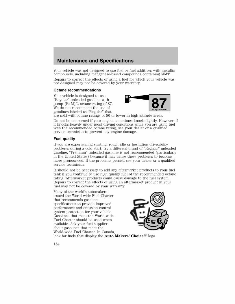
Your vehicle was not designed to use fuel or fuel additives with metalliccompounds, including manganese-based compounds containing MMT.Repairs to correct the effects of using a fuel for which your vehicle wasnot designed may not be covered by your warranty.
Octane recommendationsYour vehicle is designed to use“Regular” unleaded gasoline withpump (R+M)/2 octane rating of 87.We do not recommend the use ofgasolines labeled as “Regular” thatare sold with octane ratings of 86 or lower in high altitude areas.Do not be concerned if your engine sometimes knocks lightly. However, ifit knocks heavily under most driving conditions while you are using fuelwith the recommended octane rating, see your dealer or a qualifiedservice technician to prevent any engine damage.
Fuel qualityIf you are experiencing starting, rough idle or hesitation driveabilityproblems during a cold start, try a different brand of “Regular” unleadedgasoline. “Premium” unleaded gasoline is not recommended (particularlyin the United States) because it may cause these problems to becomemore pronounced. If the problems persist, see your dealer or a qualifiedservice technician.
It should not be necessary to add any aftermarket products to your fueltank if you continue to use high quality fuel of the recommended octanerating. Aftermarket products could cause damage to the fuel system.Repairs to correct the effects of using an aftermarket product in yourfuel may not be covered by your warranty.
Many of the world’s automakersissued the World-wide Fuel Charterthat recommends gasolinespecifications to provide improvedperformance and emission controlsystem protection for your vehicle.Gasolines that meet the World-wideFuel Charter should be used whenavailable. Ask your fuel supplierabout gasolines that meet theWorld-wide Fuel Charter. In Canada,look for fuels that display the Auto Makers’ Choice� logo.
87(R+M)/2 METHOD
Maintenance and Specifications
154

Cleaner airFord endorses the use of reformulated “cleaner-burning” gasolines toimprove air quality.
Running out of fuelAvoid running out of fuel because this situation may have an adverseaffect on powertrain components.If you have run out of fuel:• You may need to cycle the ignition from OFF to ON several times afterrefueling, to allow the fuel system to pump the fuel from the tank tothe engine.
• Your “Service Engine Soon” indicator may come on. For moreinformation on the “Service Engine Soon” indicator, refer to theInstrument cluster chapter.
Fuel FilterFor fuel filter replacement, see your dealer or a qualified servicetechnician. Refer to the scheduled maintenance guide for the appropriateintervals for changing the fuel filter.
Replace the fuel filter with an authorized Motorcraft part. Thecustomer warranty may be void for any damage to the fuel systemif an authorized Motorcraft fuel filter is not used.
ESSENTIALS OF GOOD FUEL ECONOMY
Measuring techniquesYour best source of information about actual fuel economy is you, thedriver. You must gather information as accurately and consistently aspossible. Fuel expense, frequency of fill-ups or fuel gauge readings areNOT accurate as a measure of fuel economy. We do not recommendtaking fuel economy measurements during the first 1,600 km (1,000miles) of driving (engine break-in period). You will get a more accuratemeasurement after 3,000 km–5,000 km (2,000 miles-3,000 miles).
Filling the tankThe advertised fuel capacity of the fuel tank on your vehicle is equal tothe rated refill capacity of the fuel tank as listed in the Refill capacitiessection of this chapter.
The advertised capacity is the amount of the indicated capacity and theempty reserve combined. Indicated capacity is the difference in the
Maintenance and Specifications
155

amount of fuel in a full tank and a tank when the fuel gauge indicatesempty. Empty reserve is the small amount of fuel remaining in the fueltank after the fuel gauge indicates empty.The amount of usable fuel in the empty reserve varies and shouldnot be relied upon to increase driving range. When refueling yourvehicle after the fuel gauge indicates empty, you might not beable to refuel the full amount of the advertised capacity of thefuel tank due to the empty reserve still present in the tank.
For consistent results when filling the fuel tank:• Turn the engine/ignition switch to the off position prior to refueling,an error in the reading will result if the engine is left running.
• Use the same filling rate setting (low — medium — high) each timethe tank is filled.
• Allow no more than 2 automatic click-offs when filling.• Always use fuel with the recommended octane rating.• Use a known quality gasoline, preferably a national brand.• Use the same side of the same pump and have the vehicle facing thesame direction each time you fill up.
• Have the vehicle loading and distribution the same every time.
Your results will be most accurate if your filling method is consistent.
Calculating fuel economy1. Fill the fuel tank completely and record the initial odometer reading(in kilometers or miles).
2. Each time you fill the tank, record the amount of fuel added (in litersor gallons).
3. After at least three to five tank fill-ups, fill the fuel tank and recordthe current odometer reading.
4. Subtract your initial odometer reading from the current odometerreading.
5. Follow one of the simple calculations in order to determine fueleconomy:
Calculation 1: Multiply liters used by 100, then divide by totalkilometers traveled.
Calculation 2: Divide total miles traveled by total gallons used.
Keep a record for at least one month and record the type of driving (cityor highway). This will provide an accurate estimate of the vehicle’s fuel
Maintenance and Specifications
156
economy under current driving conditions. Additionally, keeping recordsduring summer and winter will show how temperature impacts fueleconomy. In general, lower temperatures give lower fuel economy.
Driving style — good driving and fuel economy habitsGive consideration to the lists that follow and you may be able to changea number of variables and improve your fuel economy.
Habits• Smooth, moderate operation can yield up to 10% savings in fuel.
• Steady speeds without stopping will usually give the best fueleconomy.
• Idling for long periods of time (greater than one minute) may wastefuel.
• Anticipate stopping; slowing down may eliminate the need to stop.
• Sudden or hard accelerations may reduce fuel economy.
• Slow down gradually.
• Driving at reasonable speeds (traveling at 88 km/h [55 mph] uses 15%less fuel than traveling at 105 km/h [65 mph]).
• Revving the engine before turning it off may reduce fuel economy.
• Using the air conditioner or defroster may reduce fuel economy.
• You may want to turn off the speed control in hilly terrain ifunnecessary shifting between third and fourth gear occurs.Unnecessary shifting of this type could result in reduced fueleconomy.
• Warming up a vehicle on cold mornings is not required and mayreduce fuel economy.
• Resting your foot on the brake pedal while driving may reduce fueleconomy.
• Combine errands and minimize stop-and-go driving.
Maintenance• Keep tires properly inflated and use only recommended size.
• Operating a vehicle with the wheels out of alignment will reduce fueleconomy.
• Use recommended engine oil. Refer to Lubricant specifications inthis chapter.
Maintenance and Specifications
157
• Perform all regularly scheduled maintenance items. Follow therecommended maintenance schedule and owner maintenance checksfound in your vehicle scheduled maintenance guide.
Conditions• Heavily loading a vehicle or towing a trailer may reduce fuel economyat any speed.
• Carrying unnecessary weight may reduce fuel economy (approximately0.4 km/L [1 mpg] is lost for every 180 kg [400 lb] of weight carried).
• Adding certain accessories to your vehicle (for example bugdeflectors, rollbars/light bars, running boards, ski/luggage racks) mayreduce fuel economy.
• Using fuel blended with alcohol may lower fuel economy.• Fuel economy may decrease with lower temperatures during the first12–16 km (8–10 miles) of driving.
• Driving on flat terrain offers improved fuel economy as compared todriving on hilly terrain.
• Transmissions give their best fuel economy when operated in the topcruise gear and with steady pressure on the gas pedal.
• Close windows for high speed driving.
EPA window stickerEvery new vehicle should have the EPA window sticker. Contact yourdealer if the window sticker is not supplied with your vehicle. The EPAwindow sticker should be your guide for the fuel economy comparisonswith other vehicles.
It is important to note the box in the lower left corner of the windowsticker. These numbers represent the Range of L/100 km (MPG)expected on the vehicle under optimum conditions. Your fuel economymay vary depending upon the method of operation and conditions.
EMISSION CONTROL SYSTEM
Your vehicle is equipped with various emission control components and acatalytic converter which will enable your vehicle to comply withapplicable exhaust emission standards. To make sure that the catalyticconverter and other emission control components continue to workproperly:
• Use only the specified fuel listed.
• Avoid running out of fuel.
Maintenance and Specifications
158

• Do not turn off the ignition while your vehicle is moving, especially athigh speeds.
• Have the items listed in your scheduled maintenance guide performedaccording to the specified schedule.
The scheduled maintenance items listed in the scheduled maintenanceguide are essential to the life and performance of your vehicle and to itsemissions system.If other than Ford, Motorcraft or Ford-authorized parts are used formaintenance replacements or for service of components affectingemission control, such non-Ford parts should be equivalent to genuineFord Motor Company parts in performance and durability.
Do not park, idle, or drive your vehicle in dry grass or other dryground cover. The emission system heats up the engine
compartment and exhaust system, which can start a fire.
Illumination of the “Service Engine Soon” light, charging system warninglight or the temperature warning light, fluid leaks, strange odors, smokeor loss of engine power, could indicate that the emission control systemis not working properly.
Exhaust leaks may result in entry of harmful and potentiallylethal fumes into the passenger compartment.
Do not make any unauthorized changes to your vehicle or engine. Bylaw, vehicle owners and anyone who manufactures, repairs, services,sells, leases, trades vehicles, or supervises a fleet of vehicles are notpermitted to intentionally remove an emission control device or preventit from working. Information about your vehicle’s emission system is onthe Vehicle Emission Control Information Decal located on or near theengine. This decal identifies engine displacement and gives some tune upspecifications.
Please consult your Warranty Guide for complete emission warrantyinformation.
Readiness for Inspection/Maintenance (I/M) testingIn some localities, it may be a legal requirement to pass an I/M test ofthe on-board diagnostics system. If your “Check Engine/Service EngineSoon” light is on, refer to the description in the Warning lights andchimes section of the Instrument cluster chapter. Your vehicle may notpass the I/M test with the “Check Engine/Service Engine Soon” light on.
Maintenance and Specifications
159
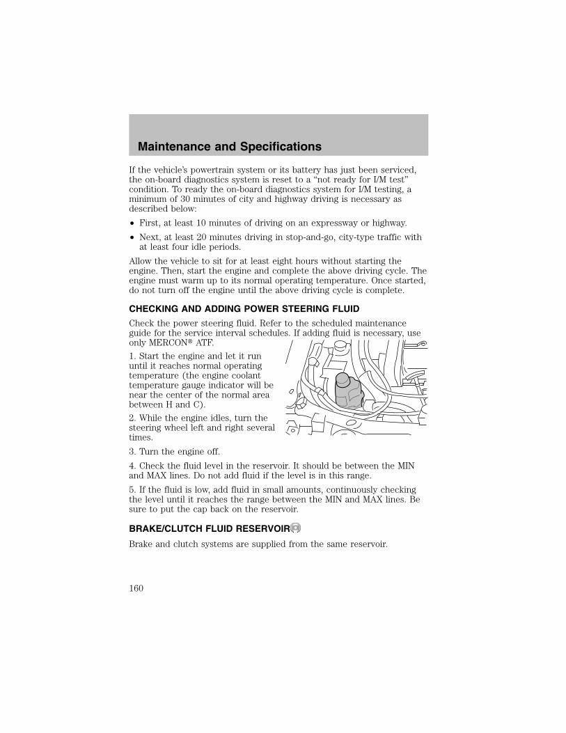
If the vehicle’s powertrain system or its battery has just been serviced,the on-board diagnostics system is reset to a “not ready for I/M test”condition. To ready the on-board diagnostics system for I/M testing, aminimum of 30 minutes of city and highway driving is necessary asdescribed below:
• First, at least 10 minutes of driving on an expressway or highway.
• Next, at least 20 minutes driving in stop-and-go, city-type traffic withat least four idle periods.
Allow the vehicle to sit for at least eight hours without starting theengine. Then, start the engine and complete the above driving cycle. Theengine must warm up to its normal operating temperature. Once started,do not turn off the engine until the above driving cycle is complete.
CHECKING AND ADDING POWER STEERING FLUID
Check the power steering fluid. Refer to the scheduled maintenanceguide for the service interval schedules. If adding fluid is necessary, useonly MERCON� ATF.
1. Start the engine and let it rununtil it reaches normal operatingtemperature (the engine coolanttemperature gauge indicator will benear the center of the normal areabetween H and C).
2. While the engine idles, turn thesteering wheel left and right severaltimes.
3. Turn the engine off.
4. Check the fluid level in the reservoir. It should be between the MINand MAX lines. Do not add fluid if the level is in this range.
5. If the fluid is low, add fluid in small amounts, continuously checkingthe level until it reaches the range between the MIN and MAX lines. Besure to put the cap back on the reservoir.
BRAKE/CLUTCH FLUID RESERVOIR
Brake and clutch systems are supplied from the same reservoir.
Maintenance and Specifications
160

The fluid level will drop slowly asthe brakes wear, and will rise whenthe brake components are replaced.Fluid levels between the “MIN” and“MAX” lines are within the normaloperating range, there is no need toadd fluid. If the fluid levels areoutside of the normal operating range, the performance of your brakesystem could be compromised, seek service from your dealerimmediately.
CLUTCH FLUID (IF EQUIPPED)The clutch master cylinder andbrake master cylinder are part ofthe same system; both are refillablethrough the brake master cylinderwith brake fluid. For moreinformation on brake fluidmaintenance, refer to Brake fluid inthis chapter.
Brake fluid is toxic. If brake fluid contacts the eyes, flush eyeswith running water for 15 minutes. Seek medical if irritation
persists. If taken internally, drink water and induce vomiting. Seekmedical attention immediately.
TRANSMISSION FLUID
Checking automatic transmission fluidRefer to your scheduled maintenance guide for scheduled intervals forfluid checks and changes. Your transaxle does not consume fluid.However, the fluid level should be checked if the transaxle is not workingproperly, i.e., if the transaxle slips or shifts slowly or if you notice somesign of fluid leakage.
Automatic transmission fluid expands when warmed. To obtain anaccurate fluid check, drive the vehicle until it is warmed up(approximately 30 km [20 miles]). If your vehicle has been operatedfor an extended period at high speeds, in city traffic during hot
MAX
MIN
Maintenance and Specifications
161
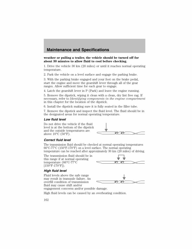
weather or pulling a trailer, the vehicle should be turned off for
about 30 minutes to allow fluid to cool before checking.
1. Drive the vehicle 30 km (20 miles) or until it reaches normal operatingtemperature.
2. Park the vehicle on a level surface and engage the parking brake.
3. With the parking brake engaged and your foot on the brake pedal,start the engine and move the gearshift lever through all of the gearranges. Allow sufficient time for each gear to engage.
4. Latch the gearshift lever in P (Park) and leave the engine running.
5. Remove the dipstick, wiping it clean with a clean, dry lint free rag. Ifnecessary, refer to Identifying components in the engine compartmentin this chapter for the location of the dipstick.
6. Install the dipstick making sure it is fully seated in the filler tube.
7. Remove the dipstick and inspect the fluid level. The fluid should be inthe designated areas for normal operating temperature.
Low fluid levelDo not drive the vehicle if the fluidlevel is at the bottom of the dipstickand the outside temperatures areabove 10°C (50°F).
Correct fluid levelThe transmission fluid should be checked at normal operating temperatures66°C-77°C (150°F-170°F) on a level surface. The normal operatingtemperature can be reached after approximately 30 km (20 miles) of driving.
The transmission fluid should be inthis range if at normal operatingtemperature (66°C-77°C[150°F-170°F]).
High fluid levelFluid levels above the safe rangemay result in transaxle failure. Anoverfill condition of transmissionfluid may cause shift and/orengagement concerns and/or possible damage.
High fluid levels can be caused by an overheating condition.
20 C 65 C
20 C 65 C
20 C 65 C
Maintenance and Specifications
162

Adjusting automatic transmission fluid levels
Before adding any fluid, make sure the correct type is used. The type offluid used is normally indicated on the dipstick and also in theLubricant specifications section in this chapter.
Use of a non-approved automatic transmission fluid may causeinternal transaxle component damage.
If necessary, add fluid in 250 mL (1/2 pint) increments through the fillertube until the level is correct.
If an overfill occurs, excess fluidshould be removed by a qualifiedtechnician.
An overfill condition oftransmission fluid may cause shift and/or engagement concernsand/or possible damage.
Do not use supplemental transmission fluid additives, treatments orcleaning agents. The use of these materials may affect transmissionoperation and result in damage to internal transmission components.
20 C 65 C
Maintenance and Specifications
163
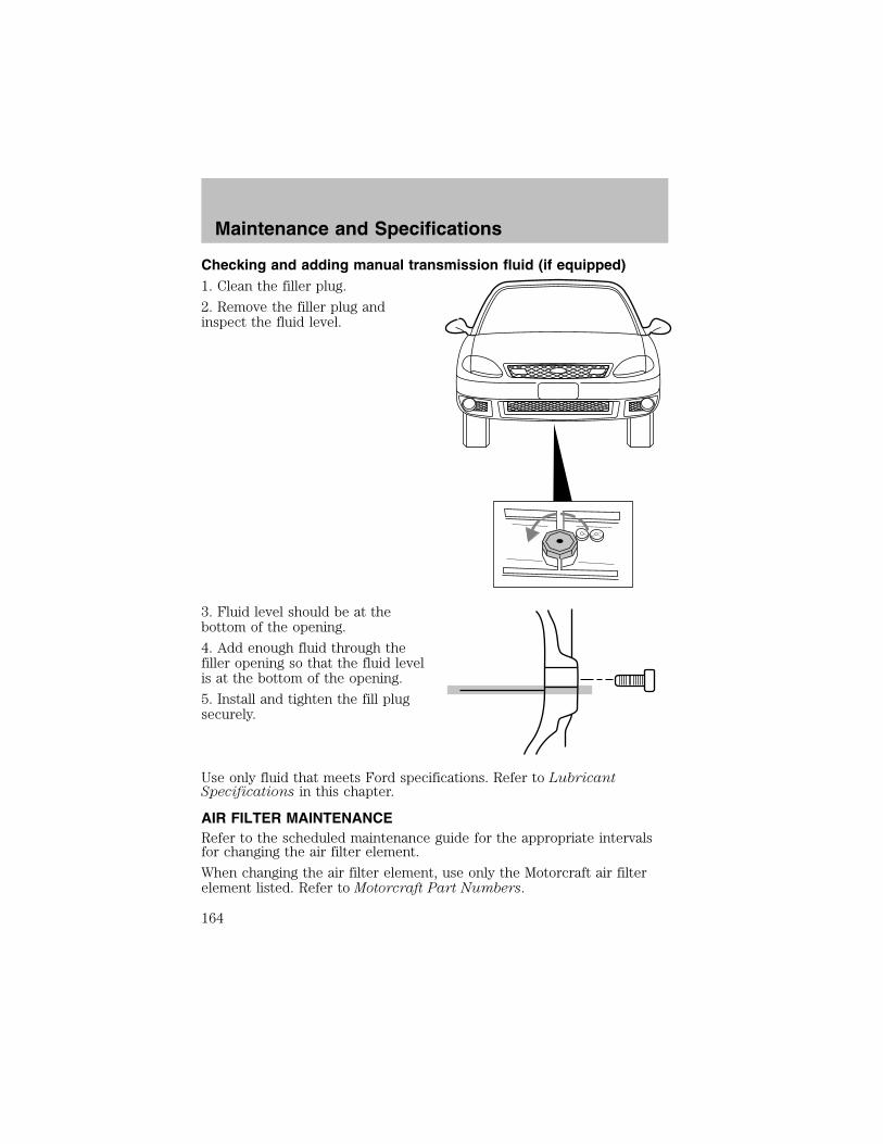
Checking and adding manual transmission fluid (if equipped)1. Clean the filler plug.
2. Remove the filler plug andinspect the fluid level.
3. Fluid level should be at thebottom of the opening.
4. Add enough fluid through thefiller opening so that the fluid levelis at the bottom of the opening.
5. Install and tighten the fill plugsecurely.
Use only fluid that meets Ford specifications. Refer to LubricantSpecifications in this chapter.
AIR FILTER MAINTENANCERefer to the scheduled maintenance guide for the appropriate intervalsfor changing the air filter element.
When changing the air filter element, use only the Motorcraft air filterelement listed. Refer to Motorcraft Part Numbers.
Maintenance and Specifications
164
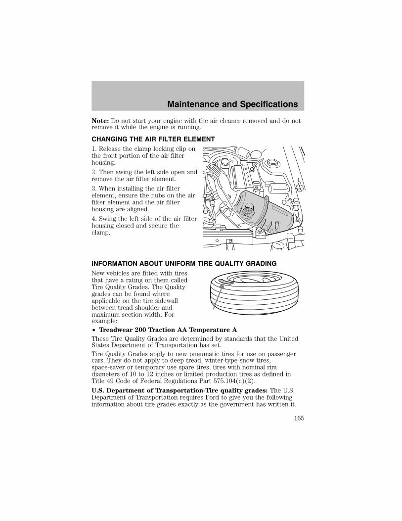
Note: Do not start your engine with the air cleaner removed and do notremove it while the engine is running.
CHANGING THE AIR FILTER ELEMENT1. Release the clamp locking clip onthe front portion of the air filterhousing.
2. Then swing the left side open andremove the air filter element.
3. When installing the air filterelement, ensure the nubs on the airfilter element and the air filterhousing are aligned.
4. Swing the left side of the air filterhousing closed and secure theclamp.
INFORMATION ABOUT UNIFORM TIRE QUALITY GRADINGNew vehicles are fitted with tiresthat have a rating on them calledTire Quality Grades. The Qualitygrades can be found whereapplicable on the tire sidewallbetween tread shoulder andmaximum section width. Forexample:• Treadwear 200 Traction AA Temperature A
These Tire Quality Grades are determined by standards that the UnitedStates Department of Transportation has set.Tire Quality Grades apply to new pneumatic tires for use on passengercars. They do not apply to deep tread, winter-type snow tires,space-saver or temporary use spare tires, tires with nominal rimdiameters of 10 to 12 inches or limited production tires as defined inTitle 49 Code of Federal Regulations Part 575.104(c)(2).
U.S. Department of Transportation-Tire quality grades: The U.S.Department of Transportation requires Ford to give you the followinginformation about tire grades exactly as the government has written it.
Maintenance and Specifications
165

TreadwearThe treadwear grade is a comparative rating based on the wear rate ofthe tire when tested under controlled conditions on a specifiedgovernment test course. For example, a tire graded 150 would wear oneand one-half (1 1/2) times as well on the government course as a tiregraded 100. The relative performance of tires depends upon the actualconditions of their use, however, and may depart significantly from thenorm due to variations in driving habits, service practices, anddifferences in road characteristics and climate.
Traction AA A B CThe traction grades, from highest to lowest are AA, A, B, and C. Thegrades represent the tire’s ability to stop on wet pavement as measuredunder controlled conditions on specified government test surfaces ofasphalt and concrete. A tire marked C may have poor tractionperformance.
The traction grade assigned to this tire is based onstraight-ahead braking traction tests, and does not include
acceleration, cornering, hydroplaning or peak traction characteristics.
Temperature A B CThe temperature grades are A (the highest), B and C, representing thetire’s resistance to the generation of heat and its ability to dissipate heatwhen tested under controlled conditions on a specified indoor laboratorytest wheel. Sustained high temperature can cause the material of the tireto degenerate and reduce tire life, and excessive temperature can lead tosudden tire failure. The grade C corresponds to a level of performancewhich all passenger car tires must meet under the Federal Motor VehicleSafety Standard No. 109. Grades B and A represent higher levels ofperformance on the laboratory test wheel than the minimum required bylaw.
The temperature grade for this tire is established for a tire thatis properly inflated and not overloaded. Excessive speed,
underinflation, or excessive loading, either separately or incombination, can cause heat buildup and possible tire failure.
SERVICING YOUR TIRES
Checking the tire pressure• Use an accurate tire pressure gauge.
Maintenance and Specifications
166

• Check the tire pressure when tires are cold, after the vehicle has beenparked for at least one hour or has been driven less than 5 km (3miles).
• Adjust tire pressure to recommended specifications found on theCertification Label.
Improperly inflated tires can affect vehicle handling and can failsuddenly, possibly resulting in loss of vehicle control, vehicle
rollover and/or personal injury.
Tire rotation
Because your vehicle’s tires perform different jobs, they often weardifferently. To make sure your tires wear evenly and last longer, rotatethem as indicated in the scheduled maintenance guide. If you notice thatthe tires wear unevenly, have them checked.
• Four tire rotation
Replacing the tiresReplace the tires when the wearband is visible through the tiretreads.
Maintenance and Specifications
167

When replacing full size tires, never mix radial bias-belted, orbias-type tires. Use only the tire sizes that are listed on the
Certification or Tire Label. Make sure that all tires are the same size,speed rating, and load-carrying capacity. Use only the tire combinationsrecommended on the label. If you do not follow these precautions,your vehicle may not drive properly and safely.
Make sure that all replacement tires are of the same size, type,load-carrying capacity and tread design (e.g., “All Terrain”,
“Touring”, etc.), as originally offered by Ford.
Failure to follow these precautions may adversely affect thehandling of the vehicle, and increase the risk of loss of vehicle
control, vehicle rollover and/or personal injury.
Tires that are larger or smaller than your vehicle’s original tires may alsoaffect the accuracy of your speedometer.
SNOW TIRES AND CHAINS
Snow tires must be the same size and grade as the tires youcurrently have on your vehicle.
The tires on your vehicle have all weather treads to provide traction inrain and snow. However, in some climates, you may need to use snowtires and chains. If you need to use snow tires and chains, it isrecommended that steel wheels are used of the same size andspecifications as those originally installed.Follow these guidelines when using snow tires and chains:• Do not use tire chains on aluminum wheels. Chains may chip thewheels.
• SAE Class S chains may be used on P185/65R14 tires.• Do not use tire chains with 38 cm (15 inch) wheel/tire options. Usingchains on this size tire may cause damage to steering, suspensionand/or body components.
• Install chains securely, verifying that the chains do not touch anywiring, brake lines or fuel lines.
• Drive cautiously. If you hear the chains rub or bang against yourvehicle, stop and re-tighten the chains. If this does not work, removethe chains to prevent damage to your vehicle.
Maintenance and Specifications
168
• If possible, avoid fully loading your vehicle.
• Remove the tire chains when they are no longer needed. Do not usetire chains on dry roads.
• The suspension insulation and bumpers will help prevent vehicledamage. Do not remove these components from your vehicle whenusing snow tires and chains.
MOTOCRAFT PART NUMBERS
Component 2.0L DOHC Zetec engine
Air filter element FA-1643Fuel filter FG-862Battery BXT-58Oil filter FL-801PCV valve EV-239ASpark plugs* AZFS-32FE**
* Refer to Vehicle Emissions Control Information (VECI) decal for sparkplug gap information.
** If a spark plug is removed for inspection, it must be reinstalled in thesame cylinder. If a spark plug needs to be replaced, use only spark plugswith the same service part number suffix letter as shown on the enginedecal.
Maintenance and Specifications
169

REFILL CAPACITIES
FluidFord Part
NameApplication Capacity
Brake fluid HighPerformanceDOT 3 MotorVehicle BrakeFluid
All Fill to line onreservoir
Engine coolant1 MotorcraftPremium EngineCoolant(green-colored)or MotorcraftPremium GoldEngine Coolant(yellow-colored)
Automatictransaxles
6.0L (6.3quarts)
Manualtransaxles
5.0L (5.3quarts)
Engine oil(includes filterchange)
Motorcraft SAE5W-20PremiumSynthetic BlendMotor Oil
All 4.25L (4.5quarts)
Fuel tankcapacity
N/A All 48.5L (12.8gallons)
Power steeringfluid
MotorcraftMERCON� ATF
All Fill to line onreservoir
Transmissionfluid Motorcraft
MERCON� ATF
Automatictransaxles
3.9L (4.1quarts)
Manualtransaxles
3.35L (3.55quarts)
Windshieldwasher fluid
MotorcraftPremiumWindshieldWasherConcentrate
All 2.2L (2.32quarts)
1Add the coolant type originally equipped in your vehicle.
Maintenance and Specifications
170

LUBRICANT SPECIFICATIONS
Item
Ford Part
Name or
Equivalent
Ford Part
Number
Ford
Specification
Brake fluid Motorcraft HighPerformanceDOT 3 MotorVehicle BrakeFluid
PM-1 ESA-M6C25-Aand DOT 3
Door latch, hoodlatch, auxiliaryhood latch,trunk latch, seattracks.
Multi-PurposeGrease
XG-4 or XL-5 ESB-M1C93-B orESR-M1C159-A
Lock cylinder Penetrating andLock Lubricant
XL-1 none
Automatictransaxle
MotorcraftMERCON� ATF
XT-2-QDX MERCON�
Manual transaxle MotorcraftMERCON� ATF
XT-2-QDX MERCON�
Engine oil Motorcraft SAE5W-20 PremiumSynthetic BlendMotor Oil
XO-5W20-QSP WSS-M2C153-Hand APICertificationMark
Constantvelocity joints
CV Joint Grease XG-5 WSS-M1C258–A1
Engine coolant1 MotorcraftPremium EngineCoolant(green-colored)
VC-4-A (US) orCXC-10(Canada)
ESE-M97B44–A
MotorcraftPremium GoldEngine Coolant(yellow-colored)
VC-7–A (VC-7–Bin Oregon)
WSS-M97B51-A1
Maintenance and Specifications
171

Item
Ford Part
Name or
Equivalent
Ford Part
Number
Ford
Specification
Power steeringfluid
MotorcraftMERCON� ATF
XT-2-QDX MERCON�
Windshieldwasher fluid
MotorcraftPremiumWindshieldWasherConcentrate
ZC-32-A WSB-M8B16–A2
1DO NOT USE Motorcraft Specialty Orange Engine Coolant VC-2 orVC-3, meeting Ford specification WSS-M97B44-D (orange in color) Referto Adding engine coolant, in this chapter.
ENGINE DATA
Engine 2.0L DOHC Zetec engine
Cubic inches 121Required fuel 87 octaneFiring order 1-3-4-2Spark plug gap 1.22-1.32 mm (0.048-0.052 inch)Ignition system DISCompression ratio 9.6:1
VEHICLE DIMENSIONS
Vehicle dimensions mm (in)
(1) Overall length 4451.0 (175.2)(2) Overall width 1712.0 (67.4)(3) Overall height 1328.4 (52.3)(4) Wheelbase 2499.0 (98.4)(5) Track - Front 1435.1 (56.5)(5) Track - Rear 1435.1 (56.5)
Maintenance and Specifications
172
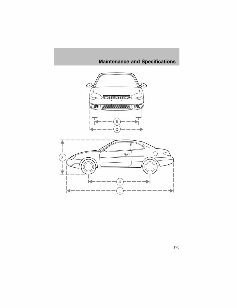
2
55
4
3
1
Maintenance and Specifications
173

IDENTIFYING YOUR VEHICLE
Certification labelThe National Highway Traffic SafetyAdministration Regulations requirethat a Certification label be affixedto a vehicle and prescribe where theCertification label may be located.The Certification label is located onthe front door latch pillar on thedriver’s side.
Vehicle identification number (VIN)The vehicle identification number isattached to a metal tag and islocated on the driver sideinstrument panel. (Please note thatin the graphic XXXX isrepresentative of your vehicleidentification number.)
XXXXXXXXXXXXXXXXX
Maintenance and Specifications
174
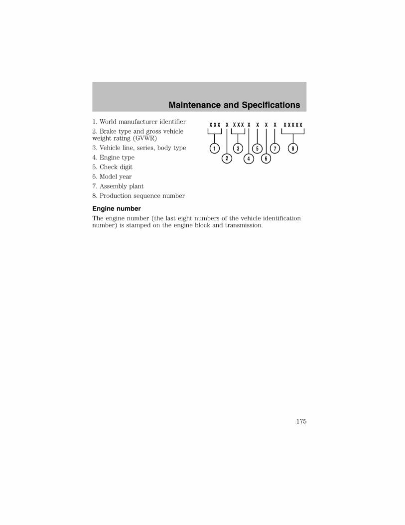
1. World manufacturer identifier
2. Brake type and gross vehicleweight rating (GVWR)
3. Vehicle line, series, body type
4. Engine type
5. Check digit
6. Model year
7. Assembly plant
8. Production sequence number
Engine numberThe engine number (the last eight numbers of the vehicle identificationnumber) is stamped on the engine block and transmission.
Maintenance and Specifications
175

FORD ACCESSORIES FOR YOUR VEHICLEA wide selection of genuine Ford accessories are available for yourvehicle through your local authorized Ford, Lincoln, Mercury or Ford ofCanada dealer. These quality accessories have been specificallyengineered to fulfill your automotive needs; they are custom designed tocomplement the style and aerodynamic appearance of your vehicle. Inaddition, each accessory is made from high quality materials and meetsor exceeds Ford’s rigorous engineering and safety specifications. FordMotor Company will repair or replace any properly dealer-installed Fordaccessory found to be defective in factory-supplied materials orworkmanship during the warranty period, as well as any componentdamaged by the defective accessory. The accessory will be warranted forwhichever provides you the greatest benefit:
• 12 months or 20,000 km (12,000 miles) (whichever occurs first), or
• the remainder of your new vehicle limited warranty.
This means that genuine Ford accessories purchased along with yournew vehicle and installed by the dealer are covered for the full length ofyour New Vehicle’s Limited Warranty — 3 years or 60,000 km (36,000miles) (whichever occurs first). Contact your dealer for details and acopy of the warranty.
Not all accessories are available for all models.
Vehicle SecurityRemote keyless entry
Wheel locks
Vehicle security systems
Comfort and convenienceCargo net
Cargo organizer
Engine block heater
Remote start system
Smoker’s package
Accessories
176
Travel equipmentAuto headlamps with daytime running lights (DRL)Console armrestDaytime running lights (DRL)Electrochromic inside mirror with compassElectrochromic inside mirror with compass and temperature displayHighway safety kit
First aid kit
Removable luggage rack
Removable luggage rack adapters (bike, ski and snowboard)
Speed control
Protection and appearance equipmentAir bag anti-theft locks
All-weather floor mats
Car cover
Cargo liner
Carpet floor mats
Flat splash guards
Front end covers (full)
Molded splash guards
Rear decklid spoiler
Universal floor mats
For maximum vehicle performance, keep the following information inmind when adding accessories or equipment to your vehicle:
• When adding accessories, equipment, passengers and luggage to yourvehicle, do not exceed the total weight capacity of the vehicle or ofthe front or rear axle (GVWR or GAWR as indicated on the Safetycompliance certification label). Consult your dealer for specific weightinformation.
• Loaded vehicles, with a higher center of gravity, may handledifferently than unloaded vehicles. Extra precautions, such as lowerspeeds and increased stopping distance, should be taken when drivinga heavily loaded vehicle.
Accessories
177

• The Federal Communications Commission (FCC) and Canadian RadioTelecommunications Commission (CRTC) regulate the use of mobilecommunications systems - such as two-way radios, telephones andtheft alarms - that are equipped with radio transmitters. Any suchequipment installed in your vehicle should comply with FCC or CRTCregulations and should be installed only by a qualified servicetechnician.
• Mobile communications systems may harm the operation of yourvehicle, particularly if they are not properly designed for automotiveuse or are not properly installed. When operated, such systems maycause the engine to stumble or stall or cause the transmission to bedamaged or operate improperly. In addition, such systems may bedamaged or their performance may be affected by operating yourvehicle. (Citizens band [CB] transceivers, garage door openers andother transmitters with outputs of five watts or less will not ordinarilyaffect your vehicle’s operation.)
• Ford cannot assume responsibility for any adverse effects or damagethat may result from the use of such equipment.
Accessories
178

A
ABS (see Brakes) .......................89Air bag supplemental restraintsystem ..........................................69and child safety seats ..............71description ................................69disposal ......................................73driver air bag ............................71indicator light ...........................73operation ...................................71passenger air bag .....................71
Air cleaner filter .......164–165, 169
Air conditioningmanual heating and airconditioning system .................29
Antifreeze(see Engine coolant) ................146
Anti-lock brake system(see Brakes) ................................89
Anti-theft system ........................56arming the system ....................56disarming a triggered system ..57disarming an untriggeredsystem .......................................57
Audio system (see Radio) .........19
Automatic transaxledriving with ...............................93fluid, adding ............................161fluid, checking ........................161fluid, refill capacities ..............170fluid, specification ..................172
Automatic transmission ..............91
Axlelubricant specifications ..........171
B
Battery .......................................144
acid, treating emergencies .....144jumping a disabled battery ....114maintenance-free ....................144replacement, specifications ...169servicing ..................................144
BeltMinder ...................................65
Brakes ....................................88–89anti-lock .....................................89anti-lock brake system (ABS)warning light .............................90fluid, checking and adding ....160fluid, refill capacities ..............170fluid, specifications .........171–172lubricant specifications ..171–172parking ......................................90shift interlock ............................91
Bulbs ............................................37
C
Capacities for refilling fluids ....170
Cell phone use ............................49
Certification Label ....................174
Changing a tire .........................110
Child safety restraints ................74child safety belts ......................74
Child safety seats ........................76attaching with tether straps ....80in front seat ..............................78in rear seat ................................78
Cleaning your vehicleengine compartment ..............131instrument panel ....................133interior .....................................133plastic parts ............................132washing ....................................130waxing .....................................130wheels ......................................131wiper blades ............................132
Index
179
Climate control (see Airconditioning or Heating) ......28–29
Clock ......................................17, 25
Clutchfluid ..................................160–161operation while driving ............97recommended shift speeds ......98
Coolantchecking and adding ..............146refill capacities ................150, 170specifications ..................171–172
Cruise control(see Speed control) ....................45
Customer Assistance ................103Ford accessories for yourvehicle .....................................134Ford Extended ServicePlan ..........................................120Getting assistance outsidethe U.S. and Canada ..............126Getting roadside assistance ...103Getting the service youneed .........................................120Ordering additional owner’sliterature .................................127The Dispute SettlementBoard .......................................123Utilizing theMediation/ArbitrationProgram ...................................126
D
Defrostrear window ..............................32
Dipstickautomatic transmissionfluid ..........................................161engine oil .................................141
Doorslubricant specifications ..........171Driving under specialconditions ....................................96through water ...........................98
E
Emergencies, roadsidejump-starting ..........................114
Emission control system ..........158
Engine ........................................172cleaning ...................................131coolant .....................................146idle speed control ...................144lubricationspecifications ..................171–172refill capacities ........................170service points ..........................140starting after a collision .........104
Engine block heater ...................88
Engine oil ..................................141checking and adding ..............141dipstick ....................................141filter, specifications ........143, 169recommendations ...................143refill capacities ........................170specifications ..................171–172
Exhaust fumes ............................88
F
Floor mats ...................................50
Fluid capacities .........................170
Foglamps .....................................33
Fuel ............................................151calculating fuel economy .......155cap ...........................................153capacity ...................................170
Index
180

choosing the right fuel ...........153comparisons with EPA fueleconomy estimates .................158detergent in fuel .....................155filling your vehicle withfuel ...........................151, 153, 155filter, specifications ........155, 169fuel pump shut-off switch .....104improving fuel economy ........155octane rating ...................154, 172quality ......................................154running out of fuel .................155safety information relating toautomotive fuels .....................151
Fuses ..................................105, 107
G
Gas cap (see Fuel cap) ............153
Gas mileage(see Fuel economy) .................155
Gauges .........................................12
GAWR (Gross Axle WeightRating) .........................................99definition ...................................99driving with a heavy load ........99location ......................................99
GVWR (Gross Vehicle WeightRating) .........................................99calculating .................................99definition ...................................99driving with a heavy load ........99location ......................................99
H
Hazard flashers .........................104
Head restraints ...........................58
Headlamps ...................................33aiming ..................................34–36
bulb specifications ....................37flash to pass ..............................34high beam .................................33replacing bulbs .........................38turning on and off ....................33
Heatingheater only system ...................28heating and air conditioningsystem .......................................29
Hood ..........................................138
I
Ignition .................................84, 172
Infant seats (see Safety seats) ..76
Inspection/maintenance (I/M)testing ........................................159
Instrument panelcleaning ...................................133cluster ........................................10lighting up panel andinterior .......................................34
J
Jack ............................................110positioning ...............................110storage .....................................110
Jump-starting your vehicle ......114
K
Keyspositions of the ignition ...........84
L
Lampsbulb replacementspecifications chart ..................37
Index
181

cargo lamps ...............................34fog lamps ...................................33headlamps ...........................33, 38headlamps, flash to pass ..........34instrument panel, dimming .....34interior lamps .....................37–38replacing bulbs .............37, 40–42
Lane change indicator(see Turn signal) ........................36
Lights, warning and indicator ....10anti-lock brakes (ABS) ............90
Load limits ...................................99GAWR ........................................99GVWR ........................................99trailer towing ............................99
Lubricant specifications ...171–172
M
Manual transaxlefluid capacities ........................170lubricant specifications ..........172
Manual transmission ...................97reverse .......................................98
Mirrorsside view mirrors (power) .......45
Moon roof ....................................48
Motorcraft parts ................155, 169
O
Octane rating ............................154
Oil (see Engine oil) ..................141
P
Parking brake ..............................90
Parts (see Motorcraft parts) ....169
Power distribution box(see Fuses) ...............................108
Power door locks ........................51
Power steering ............................91fluid, checking and adding ....160fluid, refill capacity ................170fluid, specifications .........171–172
Power Windows ...........................44
R
Radio ............................................19
Rear window defroster ...............32
Relays ................................105, 110
Remote entry system .................53locking/unlocking doors ...........51opening the trunk .....................54
Roadside assistance ..................103
S
Safety belts(see Safety restraints) .........60–63
Safety defects, reporting ..........129
Safety restraints ....................60–63belt minder ...............................65cleaning the safety belts ..........68extension assembly ..................64for adults .............................61–63for children .........................73–74warning light and chime ..........64
Safety seats for children ............76
Seat belts (see Safetyrestraints) ....................................60
Seats ............................................58child safety seats ......................76
Servicing your vehicle ..............136
Index
182
Spare tire (see Changing theTire) ...........................................110
Spark plugs, specifications ......169,172
Specification chart,lubricants ...........................171–172
Speed control ..............................45
Starting your vehicle ......84–85, 87jump starting ..........................114
Steering wheelcontrols ......................................44tilting .........................................44
T
Temperature control(see Climate control) .................28
Tires ...........................110, 165–166changing ..........................110–111checking the pressure ............166replacing ..................................167rotating ....................................167snow tires and chains ............168tire grades ...............................166treadwear ................................166
Towing .......................................100trailer towing ..........................100wrecker ....................................119
Transaxlefluid, refill capacities ..............170lubricant specifications ..........172
Transmissionautomatic operation .................91
fluid, checking and adding(automatic) .............................161fluid, checking and adding(manual) .................................164lubricant specifications ..........171manual operation ......................97
Trunk ...........................................51remote release ....................49, 54
Turn signal ..................................36
V
Vehicle dimensions ...................172
Vehicle Identification Number(VIN) ..........................................174
Vehicle loading ............................99
Ventilating your vehicle .............88
W
Warning lights (see Lights) .......10
Washer fluid ..............................141
Water, Driving through ...............98
Windowspower .........................................44
Windshield washer fluid andwiperschecking and adding fluid .....141operation ...................................43replacing wiper blades .............44
Wrecker towing .........................119
Index
183

184