03 Digital Image Processing
79
DIGITAL IMAGE PROCESSING
-
Upload
nabilah-aziz -
Category
Documents
-
view
219 -
download
2
Transcript of 03 Digital Image Processing

DIGITAL IMAGE PROCESSING
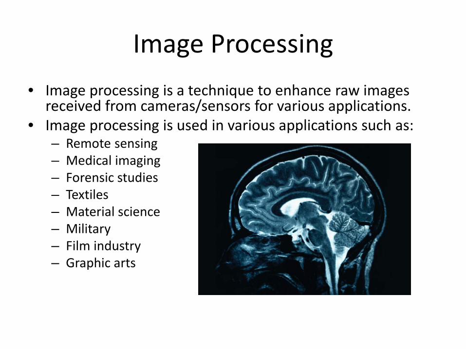
Image Processing • Image processing is a technique to enhance raw images
received from cameras/sensors for various applications. • Image processing is used in various applications such as:
– Remote sensing – Medical imaging – Forensic studies – Textiles – Material science – Military – Film industry – Graphic arts

Digital Image Processing (DIP)
• Digital image processing can be defined as the science of modifying digital images by means of a digital computer. Since both the images and the computers that process them are digital in nature, we will focus exclusively on digital image processing.
• The changes that take place in the images are usually performed automatically and rely on carefully designed algorithms.

DIP vs. Image Manipulation
• We refer to the latter as image manipulation to make this distinction more explicit.
• In contrast with another scenario, such as touching up a photo using an airbrush tool in a photo editing software
• Images are processed manually and the success of the task depends on human ability and dexterity

Advantages of DIP
• Versatility • Repeatability • The preservation of original data precision
Techniques in DIP
• Image Representation • Image Preprocessing • Image Enhancement • Image Restoration • Image Analysis • Image Reconstruction • Image Compression

Image Representation
• An image defined in the ‘real world’ is considered to be a function of two real variables, f(x,y) with f as the amplitude (e.g. brightness) of the image at the real coordinate position (x,y).
• The effect of digitization is shown in Figure.

Image Preprocessing i) Magnification
• To magnify an image by a factor of 2, each pixel of the original image is replaced by a block of 2x2 pixels, all with the same brightness value as the original pixel.

Image Preprocessing ii) Reduction
• To reduce a digital image to the original data, every mth row and mth column of the original imagery is selected and displayed.

Rotation
• Rotation is used in image mosaic, image registration etc.
• One of the techniques of rotation is 3-pass shear rotation, where rotation matrix can be decomposed into three separable matrices.
• 3-pass shear rotation
• 𝑅𝑅 = 𝑐𝑐𝑜𝑜𝑜𝑜 ∝ −𝑜𝑜𝑠𝑠𝑠𝑠 ∝𝑜𝑜𝑠𝑠𝑠𝑠 ∝ 𝑐𝑐𝑜𝑜𝑜𝑜 ∝
• = 1 −𝑡𝑡𝑡𝑡𝑠𝑠 ∝/20 1
1 0𝑜𝑜𝑠𝑠𝑠𝑠 ∝ 1 1 −𝑡𝑡𝑡𝑡𝑠𝑠 ∝/20 1

Image Enhancement
• Contrast Stretching • Noise Filtering • Histogram Enhancement
Contrast enhancement by using histogram equalization

Noise Filtering
• Noise filtering is used to filter the unnecessary information from an image.
• It is also used to remove various types of noises from the images.
• Various filters like low pass, high pass, mean, median etc., are available.
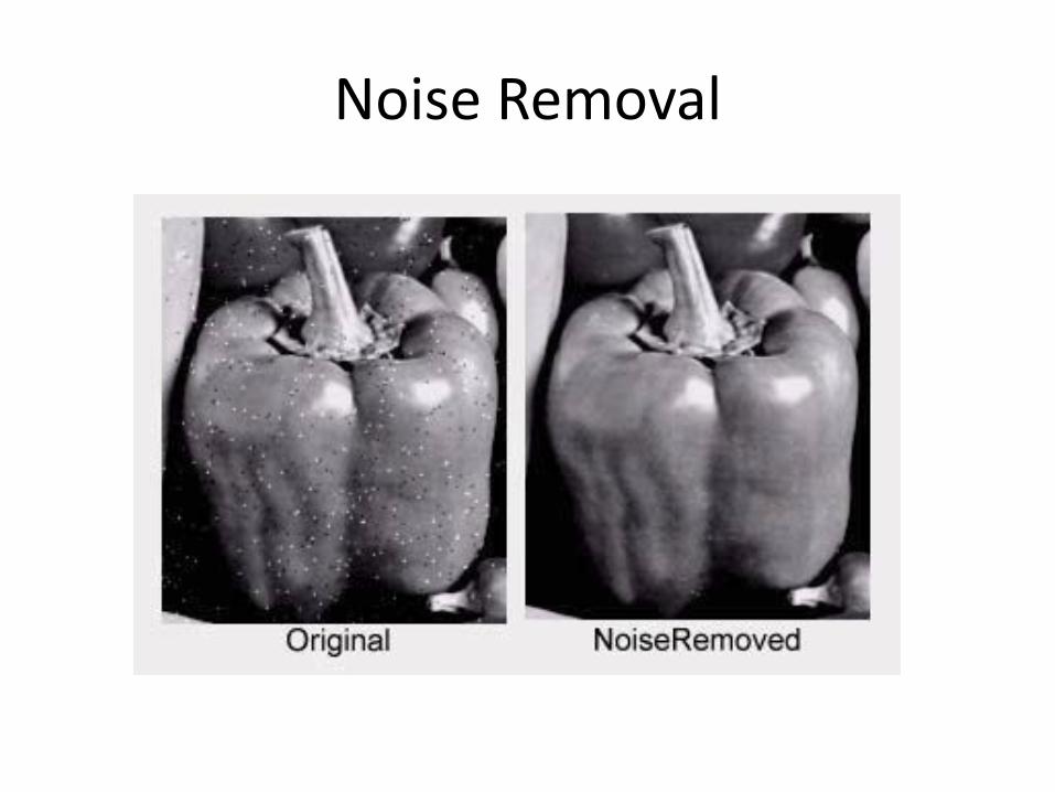
Noise Removal

Edge Enhancement
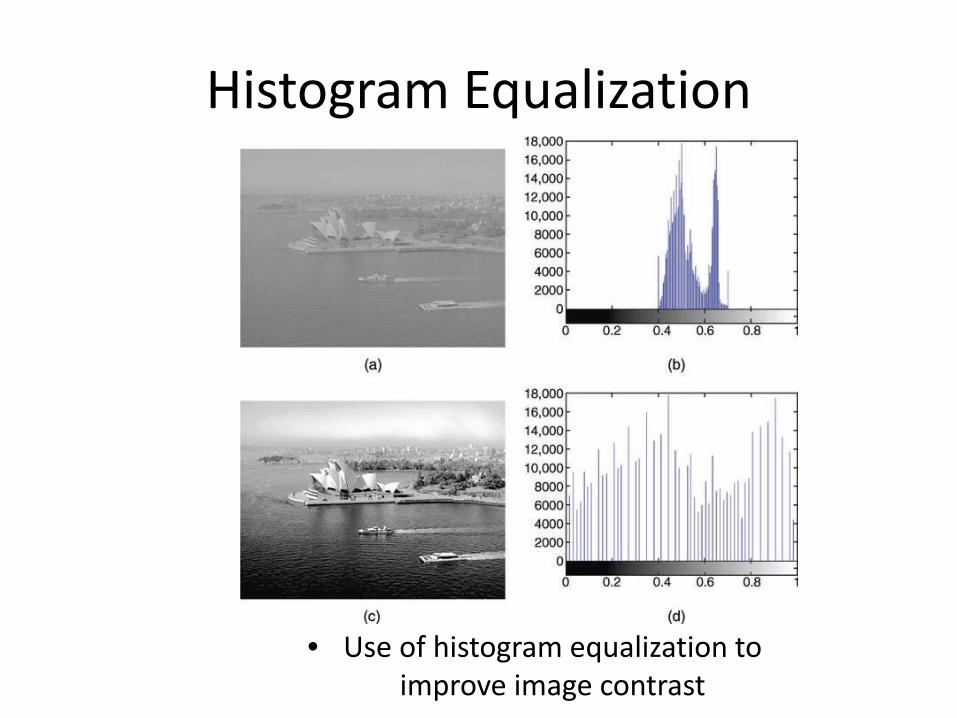
Histogram Equalization
• Use of histogram equalization to improve image contrast

Image Analysis
• Image analysis is concerned with making quantitative measurements from an image to produce a description of it.
• Image analysis techniques require extraction of certain features that aid in the identification of the object.
• Quantitative measurements of object features allow classification and description of the image.

Image Extraction

Image Segmentation
• Image segmentation is the process that subdivides an image into its constituent parts or objects.
• Segmentation (detection and extraction) • The level to which this subdivision is carried
out depends on the problem being solved, i.e., the segmentation should stop when the objects of interest in an application have been isolated

Image Segmentation
Image segmentation and labelling

Classification
• Classification is the labeling of a pixel or a group of pixels based on its grey value.
• Classification is one of the most often used methods of information extraction.
• In Classification, usually multiple features are used for a set of pixels i.e., many images of a particular object are needed.

Image Classification

Classification
• Three types of object exist in this image: pine-nuts, lentils and pumpkin seeds.
• The image on the right has been processed to extract two: circularity and line-fit error

Image Reconstruction
• Image reconstruction from projections is a special class of image restoration problems where a two- (or higher) dimensional object is reconstructed from several one-dimensional projections.

Image Compression
• Compression is a very essential tool for archiving image data, image data transfer on the network etc.
• They are various techniques available for lossy and lossless compressions.
• One of most popular compression techniques, JPEG (Joint Photographic Experts Group) uses Discrete Cosine Transformation (DCT) based compression technique.

Image Compression
Example image compressed using lossless and varying levels of lossy compression

IMAGE PROCESSING BASICS

Gray-Level Images
• Figure shows a grayscale image and a 6 × 6 detailed region, where brighter pixels correspond to larger values.
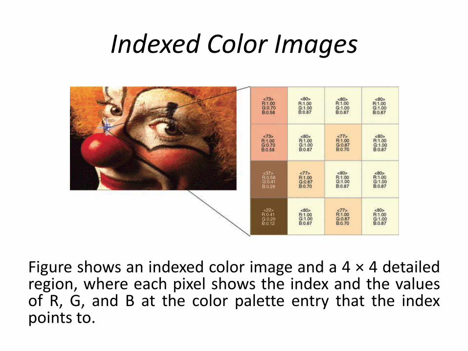
Indexed Color Images
Figure shows an indexed color image and a 4 × 4 detailed region, where each pixel shows the index and the values of R, G, and B at the color palette entry that the index points to.

Pixels Within Neighborhood
• The pixels surrounding a given pixel constitute its neighborhood
• Most neighborhoods used in image processing algorithms are small square arrays with an odd number of pixels

Concept of Neighborhood
• Concept of neighborhood of pixel p (from an image topology perspective): – (a) 4-neighborhood; – (b) diagonal neighborhood; – (c) 8-neighborhood.

Image Processing Operations
• Operations in the Spatial Domain: Arithmetic calculations and/or logical operations are performed on the original pixel values. Divided into three types: – Global Operations: Entire image is treated uniformly.
Example: contrast adjustment – Neighborhood-Oriented Operations: Treated on a
pixel-by-pixel basis. Example: spatial-domain filters. – Operations Combining Multiple Images: Two or more
images are used as an input and the result is obtained by applying a (series of) arithmetic or logical operator(s) to them.

Image Processing Operations
• Operations in a Transform Domain: Here, the image undergoes a mathematical transformation—such as Fourier transform (FT) or discrete cosine transform (DCT)—and the image processing algorithm works in the transform domain.
• Example: frequency-domain filtering techniques.

Neighborhood-Oriented Operations
• Neighborhood-oriented (also known as local or area) consist of determining the resulting pixel value at coordinates (x, y) as a function of its original value and the value of (some of) its neighbors
• Typically using a convolution operation. • The convolution of a source image with a small
2D array (known as window, mask) produces a destination image in which each pixel value depends on its original value and the value of (some of) its neighbors.

Operations Combining Multiple Images
Figure shows schematically how pixel-by-pixel operations work.

Operations Combining Multiple Images
• Logic operations on binary images

DITHERING

Dithering
• RGB color (24 bits) – image files can be quite large
• Using 8 bits can reduce the file size.
• Some of the colors will have to be approximated using colors in the chosen 256-color palette
• May lose some of the colors in the original image

Dithering
• Dithering is a technique for approximating a color that is unavailable in colors palette.
• Because the pixels are so small and close together, the eye blends the colors
• Three dithering algorithms: random, pattern and error diffusion dithering.

Example
• Example: grayscale photo with resolution of 225x180
• Close-up, the pixels are in varying shades of gray
• What if you wanted to use only one bit for each pixel in a grayscale image?
• This would mean, each pixel would have only one of two values (0, black or 1, white)

Threshold Dithering
• The simplest way to display a grayscale image using only black and white pixels by the following:
• If a pixel value is greater than 127, make it white. Otherwise, make it black. (Why 127?)
• This is called threshold dithering.

Dithering Algorithms
• Random, Pattern and Error Diffusion Dithering
• These dithered versions of the picture are a little better than thresholding in the previous example.
• They create the effect of shades of gray
• How the dithering algorithms are implemented?

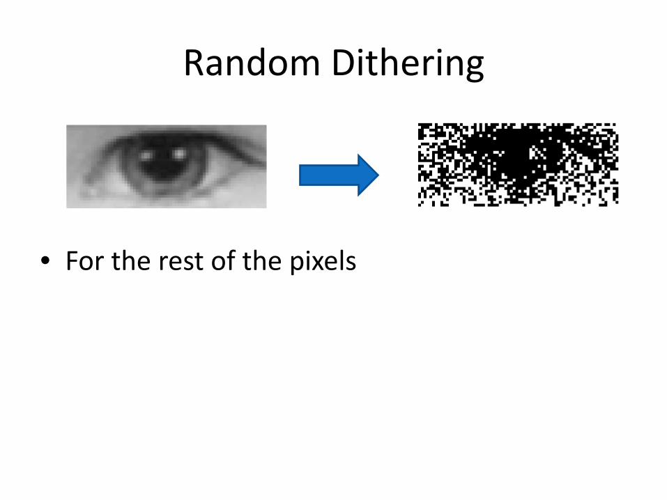
Random Dithering • For each pixel, a random
number is generated. • If the pixel value is less than the
random number, a bit of 0 is stored in the dithered image, making the pixel black. Otherwise, 1 is stored – pixel white.
• In contrast to thresholding, random dithering inserts random ‘noise’ into the picture, which breaks up the solid areas of black and white.

Random Dithering
• The value of the selected pixel is 146.
• Picture of an eye (zoomed from the original resolution 288x120).
• The tiny red square indicates which pixel is being processed.
• Supposedly, random number is 77.
• Is 146<77 ?

Random Dithering
• The pixel value >= random number. • Therefore, the square is white. • Replaced the pixel with WHITE pixel
Random Dithering
• For the rest of the pixels

Random Dithering
• Randomly dithered eye in black and white compared to the undithered eye in grayscale.
• The eye is magnified by a factor of 16.
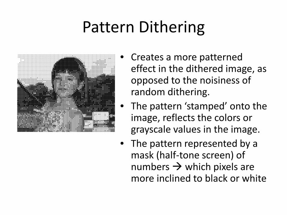
Pattern Dithering
• Creates a more patterned effect in the dithered image, as opposed to the noisiness of random dithering.
• The pattern ‘stamped’ onto the image, reflects the colors or grayscale values in the image.
• The pattern represented by a mask (half-tone screen) of numbers which pixels are more inclined to black or white

The Mask
• Supposedly, we use a pattern that represented by the mask below:
• The mask is successively placed over 3x3 blocks of pixels in the image.
• A small portion of the pixel data from the eye we just randomly dithered is given to the right.

Normalizing
• Normalize the pixel values so that they are between 0 and 9, like mask value.
• Divide by 28 • Drop the remainder

Normalizing
• After divide by 28

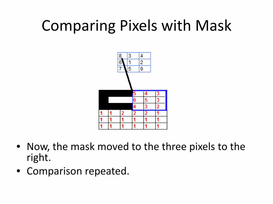
Comparing Pixels with Mask
• Is pixel value > mask value? • YES – white • NO - black
Comparing Pixels with Mask
• Now, the mask moved to the three pixels to the right.
• Comparison repeated.

Pattern Dithering

Error Diffusion Dithering
• Creates a good simulation of grayscale values on many types of images.
• The difference between a pixel’s grayscale value and the closest white or black pixel (pixel’s “error”) – is spread among neighboring pixels.
Also known as Floyd-Steinberg Algorithm

Error Diffusion Dithering
• The algorithm: • For each pixel p, the error
is distributed in a manner reflected in the pattern below:
• Notice that the number 7, 3, 5 and 1 add up to 16
• The pattern symbolizes: – P is the ‘central’ pixel,
whose error is being distributed
– The pixel to the right of p gets 7/16 of the error
– The pixel below p gets 5/16 of the error
– The pixel below and to the left gets 3/16 of the error
– The pixel below and to the right gets 1/16 of the error
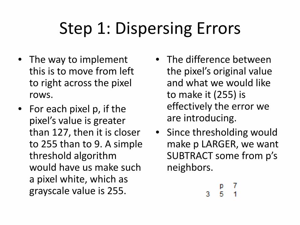
Step 1: Dispersing Errors • The way to implement
this is to move from left to right across the pixel rows.
• For each pixel p, if the pixel’s value is greater than 127, then it is closer to 255 than to 9. A simple threshold algorithm would have us make such a pixel white, which as grayscale value is 255.
• The difference between the pixel’s original value and what we would like to make it (255) is effectively the error we are introducing.
• Since thresholding would make p LARGER, we want SUBTRACT some from p’s neighbors.

• If the pixel is closer to 0, then thresholding would make it black (or 0).
• Since thresholding would make such a pixel SMALLER, we should ADD a portion of the error to each of the neighboring pixels.
• The error is the difference between the pixel’s original value and 0 – or simply the pixel’s original value.

• First, position the mask over a portion of the pixels in the original image.

• Look at the pixel value corresponding to the space marked p.
• The pixel has a value of 75.
• 75 < 127 • In threshold dithering, we
would make this pixel black – 0.
• Since, we decreasing this pixel’s value from 75 to 0, we’ll distribute 75 among the neighboring pixels.

• The pixel to the right of pixel p, (value 119), gets 7/16 of the error.
• 119 + (75*7/16) = 119+33 = 152
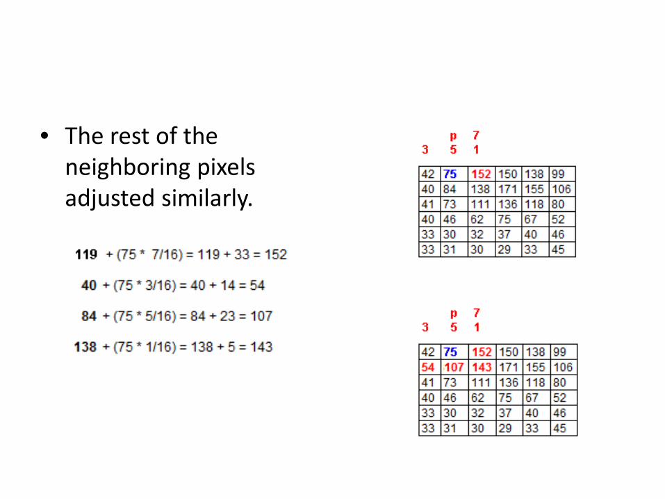
• The rest of the neighboring pixels adjusted similarly.

• Then the mask is moved to the right one pixel and the process is repeated.

Step 2: Thresholding
• The pixel data after the error has been spread across this portion of the image.
• The second step, use these new values, comparing them to the threshold value of 127.
• If a pixel’s value > 127, changed to 1 (white)
• If less than or equal to 127, changed to 0 (black)

• Pixel’s value > 127, changed to 1 (white) • Pixel’s value <= 127, changed to 0 (black)

Error Diffusion Dithering

Color Dithering
• The techniques are essentially the same with color images.
• Option: when convert and RGB to indexed color mode.

Uniform Quantization
(1 bit)
Original (8 bits)
Random Dither (1 bit)

Random Dither (1 bit)
Original (8 bits)
Ordered Dither (1 bit)
Floyd-Steinberg Dither (1 bit)

Original image Web-safe palette, no dithering Web-safe palette, FS dithering
Optimized 256 color palette Optimized 16 color palette Optimized 16 color palette FS dithering No dithering FS dithering

PIXEL POINT PROCESSING

Histogram for Image Processing
• The horizontal represents grayscale values from 0 (black) to 255 (white)
• Each of the bars represents the number of pixels of that color value in the image.
• This histogram can be generated from digital camera, Adobe Photoshop etc.
Global histogram

Histogram
• Mean,
• Std Dev,
• Median
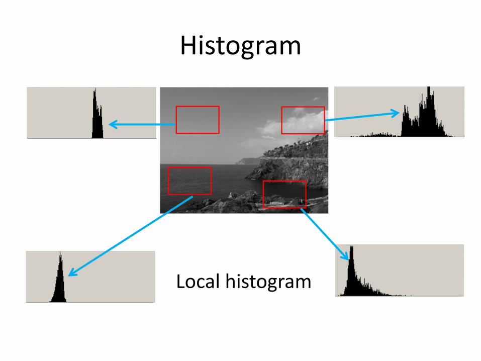
Histogram
Local histogram

Histogram for Colors

Composite RGB Histogram

Luminosity Histogram

Brightness and Contrast Adjustment
Before After

Transform Curves Function
a) The output equals the input.
b) Lightens all the pixels in the image by a constant amount.
c) Darkens all the pixels in the image by a constant amount.
d) Inverts the image, reversing dark pixels for light ones.
e) Threshold function, which makes all the pixels either black or white. A pixel with a value below 128 becomes black, and all the rest become white.
f) Increases contrast. Darks become darker and lights become lighter.

Transform Curves Function