03-1F6001-eIH Cover · PDF fileMR. MOHAMMAD SADIQ EMBANKMENT RECONSTRUCTION/GABION WALL...
47
FOR CONTRACT NO.: 03-1F6004 INFORMATION HANDOUT GEOTECHNICAL DESIGN REPORT PRELIMINARY SITE INVESTIGATION TRANSMITTAL, dated October 6, 2011 ROUTE: 03-ED-193-23.4
-
Upload
truongdang -
Category
Documents
-
view
213 -
download
1
Transcript of 03-1F6001-eIH Cover · PDF fileMR. MOHAMMAD SADIQ EMBANKMENT RECONSTRUCTION/GABION WALL...

FOR CONTRACT NO.: 03-1F6004
INFORMATION HANDOUT
GEOTECHNICAL DESIGN REPORT
PRELIMINARY SITE INVESTIGATION TRANSMITTAL, dated October 6, 2011
ROUTE: 03-ED-193-23.4

State of California Business, Transportation and Housing Agency Department of Transportation
“Caltrans improves mobility across California”
M e m o r a n d u m Flex your power! Be energy efficient!
To: MR. MOHAMMAD U. SADIQ Date: January 27, 2012 Senior Transportation Engineer District 3 File: 03-ED-193-PM 23.3/23.5 North Region Division of Engineering 03-1F6001 Design Branch S6 0300020566
Reconstruction of Embankment Slope with Gabion Wall
From: DEPARTMENT OF TRANSPORTATION
Division of Engineering Services Geotechnical Services
Subject: Geotechnical Design Report
INTRODUCTION As requested, the Office of Geotechnical Design - North (OGDN) of Geotechnical Services is providing a limited geotechnical evaluation for the gabion wall proposed for the subject embankment reconstruction project located on State Route (SR) 193 around PM 23.45, in El Dorado County. Scope of work The scope of our work included performing a literature and historical review in an effort to obtain geological and geotechnical data pertaining to the subject site that could provide insight into the design and construction of the proposed gabion wall. The historical review included searching Caltrans intranet as-built and geotechnical report records from the Bridge Inspection Records Information System (BIRIS), the Document Retrieval System (DRS), and the Digital Archive of Geotechnical Data (GeoDOG) databases Based on the request from Design Branch S6, a subsurface exploration and testing program (as required by Caltrans Bridge Design Specifications Article 5.3, August 2004) has been specifically omitted from the OGDN scope of work. Our field investigation was limited to visual observations made during a site visit by an OGDN engineer and bulk sampling of near-surface materials, followed by engineering analysis and preparation of this report summarizing our findings, conclusions and recommendations.

MR. MOHAMMAD SADIQ EMBANKMENT RECONSTRUCTION/GABION WALL January 27, 2012 ED 193 PM 23.3/23.5 03-1F6001 0300020566 Page 2
“Caltrans improves mobility across California”
Proposed Structure Based on the request from the North Region Division of Engineering, Design Branch S6, the project proposes to repair a failed embankment utilizing a gabion wall for a length along the roadway of approximately 200 feet, just north of a cross-culvert at PM 23.46 on Route 193 in El Dorado County. According to Design Branch S6, the proposed gabion wall will utilize Standard Gabion Sizes presented on the 2010 Caltrans Standard Plan No. D100A, and will be configured as diagramed in Figure A of Plate No. 1. The proposed wall will roughly mimic the existing gabion wall nearby at PM 23.2 (see “Background” section, below) which has a maximum retained height of 6 feet. However, design Branch S6 has indicated that the proposed wall will extend as high as 7.5 feet. Therefore, we propose that a Letter Code D, E and/or F Standard Gabion Size (per Plan No. D100A) be placed at the top where needed as diagramed in Figure B of Plate No. 1, attached. According to the Caltrans Digital Photolog Viewer, Roadview Explorer 2.0 (http://onramp.dot.ca.gov/photolog/roadview_index.htm), the subject site is located at latitude and longitude coordinates of 38.7742378o North and 120.8205823o West (these coordinates are the basis for obtaining data in this report available through GIS related information sources). Background Project Site PM 23.4 Director’s Order Request (“DOR”) – Funds Request (EA 03-2F100, dated Nov. 3, 2010, Reference No. 13) identifies the subject location (PM 23.45) as “Location 1”, and indicates this location to have received removal and replacement of asphalt concrete as a temporary repair of 2 inches of pavement differentials as a result of slide movement related to storm events. The DOR Funds Request further states that Location 1 was previously identified as needing a retaining wall system and was programmed to make permanent repairs as part of a Minor A Project in the 11/12 fiscal year. Pictures of the pavement failure are presented in the DOR – Funds Request (attached as Appendix A) and depict a shallow slip-out of embankment materials extending a maximum of roughly 2.5 feet into the travel way. Based on the Caltrans intranet search, no as-built, geotechnical, or other records were available for the project location. Existing Gabion Wall – PM 23.2 Review of As Built plans for the existing gabion wall at PM 23.2 (Contract No. 03-0A1104) indicate the wall was constructed in 1999 to a maximum height of 6 feet (with no

MR. MOHAMMAD SADIQ EMBANKMENT RECONSTRUCTION/GABION WALL January 27, 2012 ED 193 PM 23.3/23.5 03-1F6001 0300020566 Page 3
“Caltrans improves mobility across California”
front face batter) and a length of 65 feet. No indication was apparent on the plans that foundation improvement to the subgrade beneath the wall was performed as part of the wall construction. Based on the Caltrans intranet search, no geotechnical related records were available for the existing gabion wall location. FINDINGS Geology The project site lies within the Western Metamorphic Belt, a geologic terrane on the westerly portion of the Sierra Nevada Geomorphic Province. The Western Metamorphic Belt can be described as a northerly trending belt composed of a wide variety of metamorphic and igneous rocks. These rocks were emplaced on the western edge of North America through convergent plate-tectonism (colliding of earth’s crustal plates) that occurred from about 100 million to more than 300 million years ago (Paleozoic and Mesozoic Eras), and have been variously deformed by several episodes of folding and faulting. According to the California Geologic Survey (CGS) “Generalized Geologic Map of El Dorado County, California” (Scale 1:100,000, Reference No. 3), the immediate site of the proposed wall is located atop the Mesozoic rocks of the Mariposa Formation. The Mariposa formation is described by the CGS as dark gray slate with subordinate tuff, graywacke and conglomerate. Naturally Occurring Asbestos (NOA) The California Geologic Survey (CGS) Open File Report (OFR) 2000-002 titled “Areas More Likely to Contain Natural Occurrences of Asbestos in Western El Dorado County, California” indicates the project site to be within “areas that probably do not contain asbestos”. CGS OFR 2000-002 states that these areas generally have little or no serpentinite, ultramafic rocks or related soils, and in general, asbestos rarely occurs in these areas except in or near fault zones. Based on published geologic mapping, observations of geologic conditions made during site visits and the distance of the site from mapped faults (see “Faulting/Seismicity”, below), ) OGDN confirms that the above criteria are valid for the project site. Faulting/Seismicity The Caltrans ARS Online web tool (http://10.160.173.178/shake2/shake_index2.php) indicates that the closest “active” fault (ruptured within past 700,000 years and meeting Caltrans criteria for inclusion per Reference No. 12) to the site is the Bear Mountains fault zone (Rescue fault section) at a distance of approximately 7.1 miles westerly of the

MR. MOHAMMAD SADIQ EMBANKMENT RECONSTRUCTION/GABION WALL January 27, 2012 ED 193 PM 23.3/23.5 03-1F6001 0300020566 Page 4
“Caltrans improves mobility across California”
project site. The fault is indicated to be a “normal” fault type capable of generating a Maximum Movement Magnitude (Mmax) of 6.5. According to the Alquist-Priolo Earthquake Fault Zone Maps available through the California Geologic Survey (Reference No. 14), El Dorado County is not an “affected county”; hence, the site is not within an Alquist-Priolo Earthquake Fault Zone. No faults are known to extend close to or on the project site. Based on fault mapping of the area provided by the CGS (Scale 1:100,000, Reference No. 4), the closets inactive fault trace is roughly 0.2 miles east of the project site and is associated with the Melones Fault Zone. Bridge Design Specifications (BDS, Reference No. 9) Section 5.2.2.3 indicates that seismic forces applied for overall stability shall be based on a horizontal seismic acceleration coefficient, kh, equal to one-third of the expected peak acceleration at the site as defined in the Caltrans Seismic Hazard Map. According to the 2007 Caltrans Deterministic PGA Map (Reference No. 10), a peak ground acceleration (PGA) of 0.20g would be applicable to the site for a Vs30=2,500 ft/sec (760 m/sec, for soft bedrock). Therefore, a kh, of 0.07g was utilized for seismic design for overall stability (see Table No. 1, below). The effects of earthquake induced ground motions on the proposed retaining wall external stability (excluding overall stability) was not considered in design as the proposed wall does not support an installation for which there is a “low tolerance” for failure (per BDS Article 5.5.4). Field Investigation Project Site (PM 23.4) At the proposed gabion wall location, SR 193 has a pavement width of roughly 21 feet with little to no width for shoulders. The adjacent, uphill (left) terrain was noted to be composed of an approximately 15 to 20 feet high 0.5H:1V cutslope comprised of slate rock materials (see photographs, Plate No. 3, attached). Embankment materials downhill (right) were noted to be sloped at roughly 1.5H:1V (also confirmed by Design S6 topography data). The embankment materials appeared to be composed of excavated slate rock derived from local roadway cuts; The embankment slope extended to a maximum of roughly 50 feet vertically down from roadway level. Indications of slumping, sagging, cracks or other signs of failures were not visible on the embankment slope. No rock outcroppings were observed locally, downhill of the roadway. Hand probing of the embankment materials within 7 feet below roadway elevation was accomplished repeatedly to the full length of the hand probe (roughly 3 feet), suggesting the presence of loose, near-surface materials; below 7 feet from roadway grade the materials were resistant to hand probing, suggesting materials may have been cast on the slope or loosely placed during the DOR repair. The patched pavement area of the

MR. MOHAMMAD SADIQ EMBANKMENT RECONSTRUCTION/GABION WALL January 27, 2012 ED 193 PM 23.3/23.5 03-1F6001 0300020566 Page 5
“Caltrans improves mobility across California”
roadway was absent of any significant signs of distress. A bulk sample was obtained of the near-surface embankment materials, and was retrieved from select locations and composited for laboratory testing. Site description comments in this section were based on a site visit made on August 25, 2011. Existing Gabion Wall Site (PM 23.2) The existing gabion wall site appeared to have been constructed as indicated on the As Built project plans (see “Background” section). Embankment materials downhill, below the toe of the wall extended for about 30 feet vertically and were noted to be sloped at roughly 1.3H:1V (see photographs, Plate No. 4). The roadway pavement area behind the wall did not have any indications of post construction pavement patches. No significant distress was noted in the pavement; however, a minor (less than 3/16 inch width) longitudinal crack appears to have developed behind the heel of the wall. Laboratory Testing Bulks samples collected during our site investigation were brought to the Transportation Laboratory, composited and submitted for select testing. Laboratory testing include corrosion testing of soils (CTM 643). Sulfate content (CTM 471) and chloride content (CTM 422) testing was not performed per the 2003 Caltrans Corrosion Guidelines which states “…soil and water are not tested for chlorides and sulfates if the minimum resistivity is greater than 1,000 ohm-cm because a minimum resistivity greater than 1,000 ohm-cm indicates that the chloride and sulfate contents are low (i.e., low corrosion potential).” Laboratory testing also included triaxial shear strength testing (ASTM D 4767) of specimens remolded to 90 percent relative compaction as determined by CTM 216. Laboratory testing results are attached as Appendix C. Analysis The minimum live load surcharge for “vehicular loading” of 0.240 ksf (per Caltrans BDS Article 5.5.5.10.5) was applied in the travel way for all analyses performed. Caltrans Standard Specifications 2010, Article 72-16.02G indicates that rock-filled gabions must have a unit weight of at least 110 pcf. For a typical gabion fill porosity of 30%, this roughly corresponds to a gabion stone unit weight of 157 pcf. Initially, a slope stability limit equilibrium method (LEM) of analysis (per SlopeW software, Reference No. 11) was performed on the existing site conditions utilizing approximated, generalized strength parameters; the analysis yielded a minimum factor of safety (FS) of 1.34. Subsequently, a LEM analysis was performed for the highest proposed wall configuration and yielded a minimum FS of 1.34 for overall stability (see Plate No. 2). In accordance

MR. MOHAMMAD SADIQ EMBANKMENT RECONSTRUCTION/GABION WALL January 27, 2012 ED 193 PM 23.3/23.5 03-1F6001 0300020566 Page 6
“Caltrans improves mobility across California”
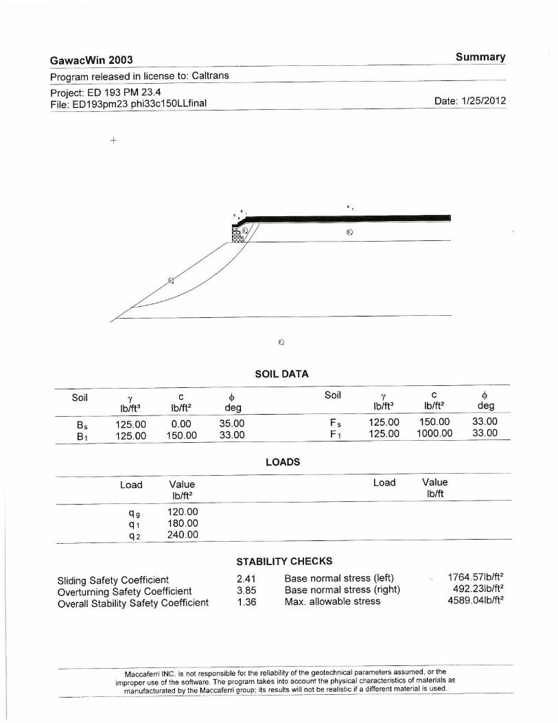
with Article 5.10.2 of Caltrans BDS Section 5, the proposed gabion wall configuration was analyzed to determine if the criteria is met for external stability of prefabricated modular walls. The gabion wall software “GawacWin 2003” provided by Maccaferri, Inc. (Reference No. 7) was utilized to check the external stability criteria, the results of which are presented as Appendix B, attached. The GawacWin output indicates a “maximum allowable stress on the foundation” of around 4,589 psf. However, limited literature is provided on the method of derivation of this value. Therefore, in accordance with Caltrans BDS Sections 4 and 5, the bearing capacity of the proposed wall foundation was analyzed based on a modified form of the general bearing capacity equation to account for the effects of the adjacent ground surface slope. Additionally, the bearing capacity was checked utilizing Shields’ 1990 Method (Reference Nos. 1 and 2). Based on an applied normal force of 6,770 lbs per foot of wall and an eccentricity of 0.56 feet (from GawacWin output), the equivalent uniform bearing pressure applied by the wall is 1,387 psf. The resulting FS against bearing failure was found to be 3.1 and 3.2 per the BDS and Shields methods, respectively. A summary of the wall stability analyses results are presented in Table No. 1, below.
Table No. 1. Stability Analysis Results
Failure Mode Analysis Source
BDS 5 Article
BDS 5 Stability Criteria
FS Results
Overall Stability (Static Loads)
SlopeW 5.2.2.3
FS > 1.3 FS = 1.34
Overall Stability (Seismic Loads
kh, = 0.07g) FS > 1.0 FS = 1.19
Sliding GawacWin
2003
5.10.2
FSSL > 1.5 FSSL = 2.41 Overturning FSOT > 2.0 FSOT = 3.85 Maximum
Eccentricity emax < B/6 emax = 0.56’ < 1’
Bearing Capacity
Caltrans BDS & Shields
Method, 1990 (FHWA-FLP-
94-006)
FS > 3.0 FS = 3.1 and 3.2

MR. MOHAMMAD SADIQ EMBANKMENT RECONSTRUCTION/GABION WALL January 27, 2012 ED 193 PM 23.3/23.5 03-1F6001 0300020566 Page 7
“Caltrans improves mobility across California”
CONCLUSIONS & RECOMMENDATIONS Based on the findings of the proposed wall analysis, and the apparent successful performance of the nearby gabion wall of similar configuration, the proposed gabion wall appears acceptable as proposed. Although both the referenced existing and proposed gabion walls do not meet the minimum embedment depth and minimum berm width requirements for prefabricated modular walls (BDS Article 5.10.1), the integrity of the proposed wall would likely not be compromised due to the relatively small proposed wall height and inherent flexibility of gabion structures. This flexible attribute is noted in the FHWA “Retaining Wall Design Guide” (Reference No. 1): “Of all of the flexible gravity structures, gabion walls typically require the least amount of foundation preparation, and they can sustain the greatest amount of differential settlement without serious distress.” Based on the loose near-surface materials encountered on the down-hill slope adjacent to the roadway (see “Field Investigation” section above), OGDN recommends the sub-excavation of materials below the outer, “toe” portion of the wall to a depth of at least 18 inches below the base of the proposed wall as diagramed in Figure B of Plate No. 1 attached. The sub-excavated materials should be replaced with “Structure Backfill” in accordance with the 2010 Caltrans Standard Specifications, Article 19-3.03E. Corrosion The USDA Web Soil Survey (Reference No. 15) indicates materials in the vicinity of the site to have a “high” rating for corrosion of steel. Based on the results of the corrosion testing (see Plate C-1), the site is considered “non-corrosive” to foundation elements per the 2003 Caltrans Corrosion Guidelines. However, these guidelines indicate that the “Gabion Mesh Corrosion” document (Reference No. 5) should be referred to for assistance regarding the corrosion evaluation and mitigation measures for gabions. In accordance with this document, OGDN has determined that the proposed site does not meet any of the indicators for “corrosive and severe exposures”, and anticipates that the proposed facility generally meets the “well-drained soil and/or dry soil conditions” criteria for “Category 2” exposure. Therefore, PVC coating in not anticipated to be required as the 0.80 oz/square foot zinc coating (per the 2010 Caltrans Standard Specifications Article 72-16.02B) should be adequate to achieve the intended service life.

MR. MOHAMMAD SADIQ EMBANKMENT RECONSTRUCTION/GABION WALL January 27, 2012 ED 193 PM 23.3/23.5 03-1F6001 0300020566 Page 8
“Caltrans improves mobility across California”
Construction Considerations Naturally Occurring Asbestos (NOA) As discussed in the “Findings” section of this report, OGDN confirms that the project site generally meets the criteria for “areas that probably do not contain asbestos”, as defined in the CGS OFR 2000-002. In consideration for the potential presence of Naturally Occurring Asbestos (NOA) materials, the North Region Hazardous Material Officer should be contacted to determine if the project has the need for Airborne Toxic Control Measures (ATCMs) during project construction If any conceptual changes are made during final project design, the Office of Geotechnical Design North should review those changes to determine if these foundation recommendations are still applicable. If you have any questions or comments, please call Mark Hagy at (916) 227-1077 or Douglas Brittsan at (916) 227-1079. MARK HAGY, P.E., G.E. Transportation Engineer Office of Geotechnical Design North, Branch C c: Doug Brittsan Najed Dakak - D02 – Proj. Mgmt. Struct. Const. RE Pending File DES OE, Office of PS&E DME GS Corporate OGDN File Attachments: References Plate No. 1: Gabion Wall Figures Plate No. 2: Overall Stability Plate No. 3: Photographs Plate No. 4: Photographs Appendix A: Director’s Order Request- Funds Request, ED 193 PM 23.45-23.75 Appendix B: GawacWin 2003 Results Appendix C: Laboratory Testing Results Plate No. C-1. Corrosion Test Results Plate No. C-2. Compaction Test Results Plate Nos. C-3a & C-3b. Consolidated Undrained Triaxial Test Results
No. GE 2838 Exp.12-31-12

MR. MOHAMMAD SADIQ EMBANKMENT RECONSTRUCTION/GABION WALL January 27, 2012 ED 193 PM 23.3/23.5 03-1F6001 0300020566 Page 9
“Caltrans improves mobility across California”
REFERENCES
1. FHWA (1994) “Retaining Wall Design Guide”, FHWA Technical Report No. FHWA-FLP-94-006, dated September 1994.
2. USDA (1998) “Application of Methods for Estimating the Bearing capacity of Spread Footings in Bridge Approach Fills”, Engineering Technical Note No. 1, U.S. Dept. of Agriculture, Natural Resources Conservation Service, dated November 1998.
3. CGS (2000) “Areas More Likely to Contain Natural Occurrences of Asbestos in Western El
Dorado County, California”, California Dept. of Conservation, Division of Mines and Geology, Open-File Report 2000-002, dated 2000.
4. CGS (2001) “Mineral Land Classification of El Dorado County, California”, California
Department of Conservation, California Geologic Survey, CGS Open-File Report 2000-03, by Lawrence L. Busch, Plate 1 Map Scale 1: 100,000, June 2001.
5. Caltrans (2001) “Gabion Mesh Corrosion – Field Study of Test Panels and Full-Scale
Facilities”, Report No. FHWA-CA-TL-99-23, Study No. F93TL02 S, 2nd Edition, dated November 2001.
6. Caltrans (2003) “Corrosion Guidelines”, Corrosion Technology Branch, Materials Engineering and Testing Services, Caltrans, Version 1.0, September 2003.
7. Maccaferri, Inc. (2003) GawacWin 2003 software, licensed to Caltrans, supplied by
Maccaferri, INC. (USA), Copyright 1997/2003, Persio L. A. Barros, GCP Engenharia, Brasil, obtained at http://www.maccaferri-canada.com/Software.aspx.
8. Caltrans (2003) “Bridge Design Specifications, Section 4 –Foundations”, dated November
2003.
9. Caltrans (2004) “Bridge Design Specifications, Section 5 –Retaining Walls”, dated August 2004.
10. Caltrans (2007) “2007 Caltrans Deterministic PGA Map”, M. Merriam, Division of
Engineering Services, and T. Shantz, Division of Research & Innovation, Caltrans, from http://dap3.dot.ca.gov/shake_stable/references/Deterministic_PGA_Map_8-12-09.pdf.
11. GEOSLOPE International Ltd (2007) SLOPE/W software, GeoStudio 2007, Version 7.17,
Build 4921, copyright 1991-2010.
12. Caltrans (2009) “Development of the Caltrans Deterministic PGA Map and Caltrans ARS Online”, M. Merriam, Geotechnical Services, and T. Shantz, Division of Research &

MR. MOHAMMAD SADIQ EMBANKMENT RECONSTRUCTION/GABION WALL January 27, 2012 ED 193 PM 23.3/23.5 03-1F6001 0300020566 Page 10
“Caltrans improves mobility across California”
Innovation, Caltrans, from http://dap3.dot.ca.gov/shake_stable/references/Deterministic_PGA_Map_and_ARS_Online_Report_ 071409.pdf.
13. Caltrans (2010) “Director’s Order Request-Funds Request”, ED 193 PM 23.45-23.75, EA
03-2F100, incident date October 24, 2010, signed November 3, 2010.
14. CGS (2011) “ Alquist-Priolo Earthquake Fault Zone Maps”, obtained from California Geologic Survey at http://www.quake.ca.gov/gmaps/ap/ap_maps.htm.
15. USDS (2011) “USDA Web Soil Survey”, http://websoilsurvey.nrcs.usda.gov/app/.USGS

Plate No. 1
03-ED-193 PM 23.3-23.5 GABION WALL
GEOTECHNICAL DESIGN REPORT
EA: 03-1F6001
Date: January 2012
GABION WALL FIGURES CALTRANS
Division of Engineering Services Geotechnical Services Office of Geotechnical Design - North
SUB-EXCAVATE AND REPLACE WITH “STRUCTURE BACKFILL” PER 2010 CALTRANS STANDARD SPECIFICATIONS
5 ft. min.
1 ft. min.
Figure B: Sub-Excavation and Recompaction Limits Scale: 1 inch = 4 feet
18 in. min.
GABION WALL
Figure A. Typical Cross Section (No Scale) Reference: Portion of “Typical Cross Sections”, Sheet X-1, 03-ED-193 PM 23.4, 0300020566ca001.dgn dated 1/26/2012, provided by the Caltrans North Region Division of Engineering - Design, Branch S6.

Plate No. 2
03-ED-193 PM 23.3-23.5 GABION WALL
GEOTECHNICAL DESIGN REPORT
EA: 03-1F6001
Date: January 2012
OVERALL STABILITY CALTRANS
Division of Engineering Services Geotechnical Services Office of Geotechnical Design - North
Note: Wall configuration and ground surface elevations based on elevations presented in “Layout”, Sheet L-1 provided by the Caltrans North Region Division of Engineering, Design Branch S6, and on OGDN field measurements on August 25, 2011.
#1 – SLATE BEDROCK
Impenetrable
#2 – EMBANKMENT (composed of locally
derived slate materials): γ = 125 pcf
ϕ'= 33o c’ = 150 psf
#3 – GABION BASKET FILL:
γ = 110 pcf ϕ = 60o
c = 5000 psf (Relatively
Impenetrable)
#4 – WALL BACKFILL: γ = 125 pcf
ϕ = 35o c = 0 psf
Circular Failure Surface yielding a minimum Static Factor of Safety of 1.34 (Bishop’s Method). TRAFFIC
SURCHARGE:240 psf
#1
Entry/ExitSearch Limits (typical)
#2
#3
#4 C L
EXISTING ROUTE 193
OG
#2
1.34 to 1.39 1.39 to 1.44
1.44 to 1.49
1.49 to 1.54
Safety Map Range of Factor of Safety
1.54 to 1.59
APPROXIMATE SCALE : 1” = 20 feet (vertical = horizontal)
0 20 40 feet

Plate No. 3
03-ED-193 PM 23.3-23.5 GABION WALL
GEOTECHNICAL DESIGN REPORT
EA: 03-1F6001
Date: January 2012
PHOTOGRAPHS PROJECT SITE
PM 23.4 CALTRANS Division of Engineering Services Geotechnical Services Office of Geotechnical Design - North
Photo No. 1. Project site vantage point view from easterly direction (photo taken on 8-25-11.
Photo No. 2. Project site viewing from southeasterly direction; Note pavement patch (photo taken on 8-25-11.
Photo No. 3. Project site viewing from northwesterly direction; Note PM 23.46 paddle marker (photo taken on 8-25-11.

Photo No. 5. Existing gabion wall (PM 23.2) viewing from easterly direction (photo taken on 8-25-11).
Plate No. 4
03-ED-193 PM 23.3-23.5 GABION WALL
GEOTECHNICAL DESIGN REPORT
EA: 03-1F6001
Date: January 2012
PHOTOGRAPHS EXISTING GABION WALL
PM 23.2 CALTRANS Division of Engineering Services Geotechnical Services Office of Geotechnical Design - North
Photo No. 4. Existing gabion wall (PM 23.2) site; vantage point view from southwesterly direction (photo taken on 8-25-11).
Photo No. 6. Existing gabion wall (PM 23.2) viewing from easterly direction; Note close-up of longitudinal pavement cracking (photo taken on 8-25-11).
GABION WALL FACE

03-1F6001
ED 193 PM 23.3-23.5
APPENDIX A
Director’s Order Request- Funds Request,
ED 193 PM 23.45-23.75


03-1F6001
ED 193 PM 23.3-23.5
APPENDIX B
GawacWin 2003 Results


03-1F6001
ED 193 PM 23.3-23.5
APPENDIX C
Laboratory Testing Results
Plate No. C-1. Corrosion Test Results Plate No. C-2. Compaction Test Results
Plate No. C-3a. Consolidated Undrained Triaxial Test Results (Total Stress) Plate No. C-3b. Consolidated Undrained Triaxial Test Results (Effective Stress)

Plate No. C-1
03-ED-193 PM 23.3-23.5 GABION WALL
GEOTECHNICAL DESIGN REPORT
EA: 03-1F6001
Date: January 2012 CORROSION TEST RESULTS CALTRANS
Division of Engineering Services Geotechnical Services Office of Geotechnical Design - North

Plate No. C-2
03-ED-193 PM 23.3-23.5 GABION WALL
GEOTECHNICAL DESIGN REPORT
EA: 03-1F6001
Date: January 2012
COMPACTION TEST RESULTS(CTM 216) CALTRANS
Division of Engineering Services Geotechnical Services Office of Geotechnical Design - North

Plate No. C-3a
03-ED-193 PM 23.3-23.5 GABION WALL
GEOTECHNICAL DESIGN REPORT
EA: 03-1F6001
Date: January 2012
CONSOLIDATED UNDRAINED TRIAXIAL TEST RESULTS
(TOTAL STRESS) CALTRANS Division of Engineering Services Geotechnical Services Office of Geotechnical Design - North
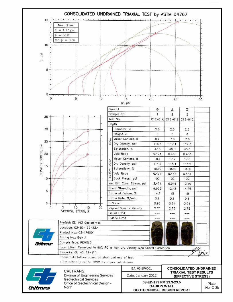
Plate No. C-3b
03-ED-193 PM 23.3-23.5 GABION WALL
GEOTECHNICAL DESIGN REPORT
EA: 03-1F6001
Date: January 2012
CONSOLIDATED UNDRAINED TRIAXIAL TEST RESULTS
(EFFECTIVE STRESS) CALTRANS Division of Engineering Services Geotechnical Services Office of Geotechnical Design - North