02.4
21
Page 1 of 21 2.4. Plant operation – wort separation 2.4.1. What is mash separation? During mashing the Amylases, Glucanases and Proteases started work. The breakdown products they produced dissolved into the mashing water. We now have to separate out this liquid, called wort from the spent grains. In Lauter Tuns and British style Mash Tuns we do this by filtering the liquid out from the mash through the remaining solid material. The bottom of the tun may be flat or sloped. It may be constructed with several concentric valleys with intervening ridges. Suspended above the true bottom of the tun is a false bottom of milled, slotted, or welded wedge wire steel plates. These act as a support for the mash. The wort filters through the mash and out through the slots to the true bottom. From there it is sent to the copper. Wort Wort Wort Wort Slot Slot MASH Plate Slots Inside of a Lauter tun showing the Slotted plates.
-
Upload
hang-u-lie -
Category
Documents
-
view
5 -
download
0
description
jhghj
Transcript of 02.4
Page 1 of 21
2.4. Plant operation – wort separation
2.4.1. What is mash separation?
During mashing the Amylases, Glucanases and Proteases started work. The breakdownproducts they produced dissolved into the mashing water. We now have to separate outthis liquid, called wort from the spent grains.
In Lauter Tuns and British style Mash Tuns we do this by filtering the liquid out from themash through the remaining solid material. The bottom of the tun may be flat or sloped. Itmay be constructed with several concentric valleys with intervening ridges. Suspendedabove the true bottom of the tun is a false bottom of milled, slotted, or welded wedge wiresteel plates. These act as a support for the mash. The wort filters through the mash andout through the slots to the true bottom. From there it is sent to the copper.
Wort Wort Wort Wort
Slot Slot
MASH
Plate
Slots
Inside of a Lauter tun showing the Slotted plates.

Page 2 of 21
You should note that the slots are only to let the wort through. They are NOT the filter.
The filter is the entire mass of solids. The husk is the most important part. This keeps thefilter bed open.
There is a second type of mash separator . This is the Mash Filter. The mash filter is like alarge press. The sections are separated by a cloth. The mash and husk are pressed ontothese. The wort is pumped through under pressure and is filtered by the solids which areretained by the filter cloths.
Again, note that the cloths are NOT the filter. They only act as a support for the solidswhich actually do the filtering.

Page 3 of 21
A modern mash filter: the Meura 2001
2.4.2. The Theory of wort separation.
Wort is separated from the husk by two physical processes:
2.4.2.1. Leaching
First of all the dissolved solids (sugars, protein etc.) need to be drawn (leached) from thegrains.
This is dependent on the concentration of dissolved solids already present. If there is a lotdissolved solids(high Gravity) then it is difficult to dissolve more. We keep theconcentration low by removing the products of leaching (drawing off wort) and replacingthem with fresh water (sparging). Leaching can be maximised by having a finer grind.
2.4.2.2. Filtration
Filtration is the separation of liquids and solids in the mash through a filter bed. The filterbed is made up of the solid material of the mash (husk and other malt debris). This issupported on a metal screen in the case of the Mash and Lauter tuns or a polypropylenefilter cloth in the case of the Mash Filter. The large particles form a bridge across the baseelement of the filter. The bed formed by these particles will in turn hold back smallerparticles. This sieving effect removes the majority of the solids present. This allowsclarified bright wort to flow in to the kettle. Fine particles clog the filter bed and result in aslow run off, or a set bed. The rate of filtration is maximised by a coarse grind.
2.4.2.3. Efficiency
The efficiency of the mash separation process is measured by:
Turn around time
The time to process a complete brew. Generally a modern brewhouse (with 7vessels) would process 8 to 10 brews every 24 hours.
Extract Efficiency
This is based on a direct comparison of the total extract (gravity x volume) collectedin fermentation vessel against the laboratory extract. Generally a modern brewhouse will recover 98% of laboratory extract.

Page 4 of 21
Wort Quality
This is more difficult to measure but typical parameters would be:
o Wort Haze in E.B.C. - should be < 50 EBC 10 minutes after the start of runoff.
o Suspended solids - no more than 10 to 15 mls as sediment after 2 hrs in anIMHOFF cone
o Dry Solids/ wort residue - Measured using centrifugation and pellet drying orin specialised heated centrifuges or filter paper. Normal values around 250to 500 p.p.m.
For the technically minded!
Filtration is generally defined in terms of Darcy’s equation:
Flow rate u = filter surface area (A) x pressure differential across filter (P)
viscosity ( x resistance to the flow of beer (L )
Therefore using this equation it is possible to predict the conditions for optimum flow:
Large surface area – the higher the flow
The higher the differential pressure – the higher the flow
The lower the wort viscosity – the higher the flow
The shallower the filter bed – the higher the flow.
Darcy’s equation describes the conditions for optimum flow not optimum wort quality.

Page 5 of 21
2.4.3. Wort separation process
Wort separation follows a similar pattern in all of the separation systems.
Firstly the strong (main) wort is separated.
Secondly, after all the strong wort has been collected the grain bed is washed with freshwater in a process called sparging. Hot water (at between 76 to 780C) is sprayed over thegrains. This passes through the grain bed. It washes out remaining wort until the requiredwort volume and gravity is collected in the wort kettle. The sparge is then stopped and theadditional wort is run to drain or weak wort recovery as required.
The sparge system may have significant effects on wort quality. If the pH of the spargewater is too high (pH > 7.2) or the sparge is continued until it reaches a low gravity (around10 Plato) it may lead to the extraction of unwanted wort compounds. This may give flavourand processing problems in the finished beer.
It is also necessary to ensure bright worts are produced.
Cloudy worts indicate the extraction of polyphenols and lipids from the malt husk. This cancause harsh flavours.
Cloudy worts can be an indication of starch granules being extracted into wort.
The extraction of these compounds are greater:
with higher wort pH (> 5.5)
with higher sparge temperatures (> 780C)
with low last running gravity's (< 10 Plato).
Page 6 of 21
2.4.4. The Lauter Tun
2.4.4.1. What does it consist of?
2.4.4.1.1. Construction
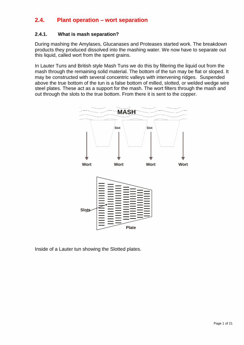
It is usually built of stainless steel or copper. It is insulated to prevent heat loss of themash. There is a vent to discharge vapour. It has a false bottom.

Page 7 of 21
Wear line
Wear line
G a p in c re a s e sw ith w e a r
No gap changewith wear
Milled slots
Wedge wire slots
2.4.4.1.2. Plates
The false bottom is built up of interlockingplates. These may have either milled slotsor they may be built up of wedge wire.
The advantage of wedge wire over cut slotsis that wear on the wire does not producean " opening" of the gap.
The plates are made in sections so that theycan be lifted. This enables them to bethoroughly cleaned if required.
2.4.4.1.3. Sparge
It has a sparging system. This is used to spray water over the mash to wash out the worts.
2.4.4.1.4. Rakes
It has a rakingsystem. Theseare knives whichcan “cut” thebed. This, whenused properly,helps thefiltration process.
There is a CIP system installed. There are spray balls or jets which clean the internalsurface and under the plates.
Raking can be continuous or using a number of discrete steps. The sparge can be addedcontinuously or as a batch addition.
2.4.4.1.5. Cleaning
Page 8 of 21
The vessel is normally thoroughly cleaned and descaled once a week with “Caustic”
2.4.4.1.6. Draw off
All Lauter tuns are fitted with a draw off device. This enables the operator to balance runoff to the differential pressure of the bed over the plates. Too much differential pressurewill pull the bed onto the plates. This will cause a set mash. Modern Lauter Tuns arecomputer controlled.
2.4.4.1.7. Mash inlet
There is an inlet for the mash. This is normally through the bottom. This cuts down onoxidation during the transfer from the mash tun.
2.4.4.2. Operation
The mash is transferred from the Mash tun into the Lauter Tun. The filter bed in the lautertun is shallow and has a large surface area. A fine grind increases the resistance to flowand this is compensated for by the use of rakes. These open the bed to allow fasterfiltration. The rakes must operate in such a way that sparge is not channelled and the filterbed is not totally disrupted. A slight increase in wort viscosity can have a dramatic effecton run off performance.
Most lauter tuns are fully automated. The wort run off rate is controlled.
Also the differential pressure above and below the lauter plates is measured andcontrolled. When this pressure falls below a set pressure it has reached a "set bed”condition. The run off is stopped and the rakes are lowered to the bottom of the bed andused to break up the bed for 5 to 10 minutes before normal filtration is resumed.
The typical run off sequences and control are shown below.
Another measurement often used to control run off is haze. The wort turbidity is measured.The contents of the lauter tun are re-circulated to ensure that only bright (haze less than 5to 12 EBC) wort runs to the kettle.
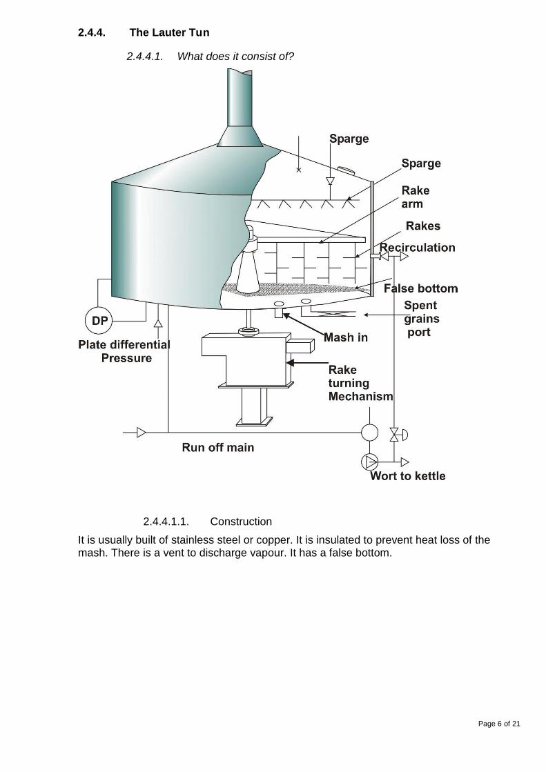
A typical lauter tun cycle to collect 1000 hl is described below.
Event Duration Volume HIUnderlettingThis covers the false bottom. It stops themash settling into the slots and blockingthem.
3 minutes 23
FillingThe mash is pumped from the mashingvessel.
11 minutes
Re-circulationWort is recirculated until it is bright.
4 minutes 20
First wortsThe strong worts are run off
41 minutes 200
Second wortsWeaker worts are run off. Sparge waterstarts to wash out the wort.
74 minutes 475
Last worts 10 minutes 141
Page 9 of 21
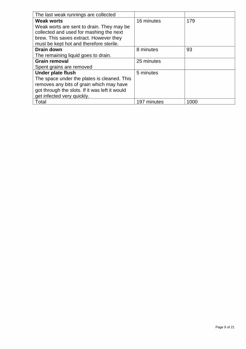
The last weak runnings are collectedWeak wortsWeak worts are sent to drain. They may becollected and used for mashing the nextbrew. This saves extract. However theymust be kept hot and therefore sterile.
16 minutes 179
Drain downThe remaining liquid goes to drain.
8 minutes 93
Grain removalSpent grains are removed
25 minutes
Under plate flushThe space under the plates is cleaned. Thisremoves any bits of grain which may havegot through the slots. If it was left it wouldget infected very quickly.
5 minutes
Total 197 minutes 1000
Page 10 of 21
2.4.5. Mash Filter
2.4.5.1. What does it consist of?
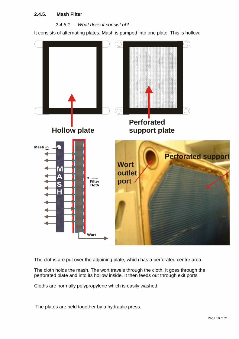
It consists of alternating plates. Mash is pumped into one plate. This is hollow:
Hollow platePerforatedsupport plate
Perforated support plateWortoutletport
The cloths are put over the adjoining plate, which has a perforated centre area.
The cloth holds the mash. The wort travels through the cloth. It goes through theperforated plate and into its hollow inside. It then feeds out through exit ports.
Cloths are normally polypropylene which is easily washed.
The plates are held together by a hydraulic press.

Page 11 of 21
Wort out
Filter plates
Mash in
A modern mash filter: theMeura 2001
The mash filter is flushed, then preheated with hot water.
The mash is then pumped into the filter through the top channel, completely filling the filterframes.
The entire transfer to the mash filter is completed in 20 to 30 minutes
If the filter is underfilled, the efficiency of the extraction process suffers significantly. Thesparge water will flow through the empty portion of the chamber.
Overfilling, on the other hand, results in excessive density. This badly affects filtrationefficiency.
When the filter is full, the wort collection system is opened. The wort is drawn horizontallythrough the filter cloths.
To achieve satisfactory clarity, the wort is normally recirculated through the filter.
Sparging is started after the first wort is partially drained but before the filter cake becomesdry.
Sparge water between 75 and 78ºC is pumped into the filter from the bottom and lastsfrom 90 to 140 minutes.
Just as with the lauter tun, the mash filter pressure differential is critical.
After the last wort, the filter is opened automatically, plate-by-plate, and spent grains fallinto a trough with a screw conveyor.
The latest Mash filters like the Meura 2001 (picture above), incorporate a flexiblemembrane around the mash in the hollow plate. Air can be applied to this membrane tosqueeze the mash.
Page 12 of 21
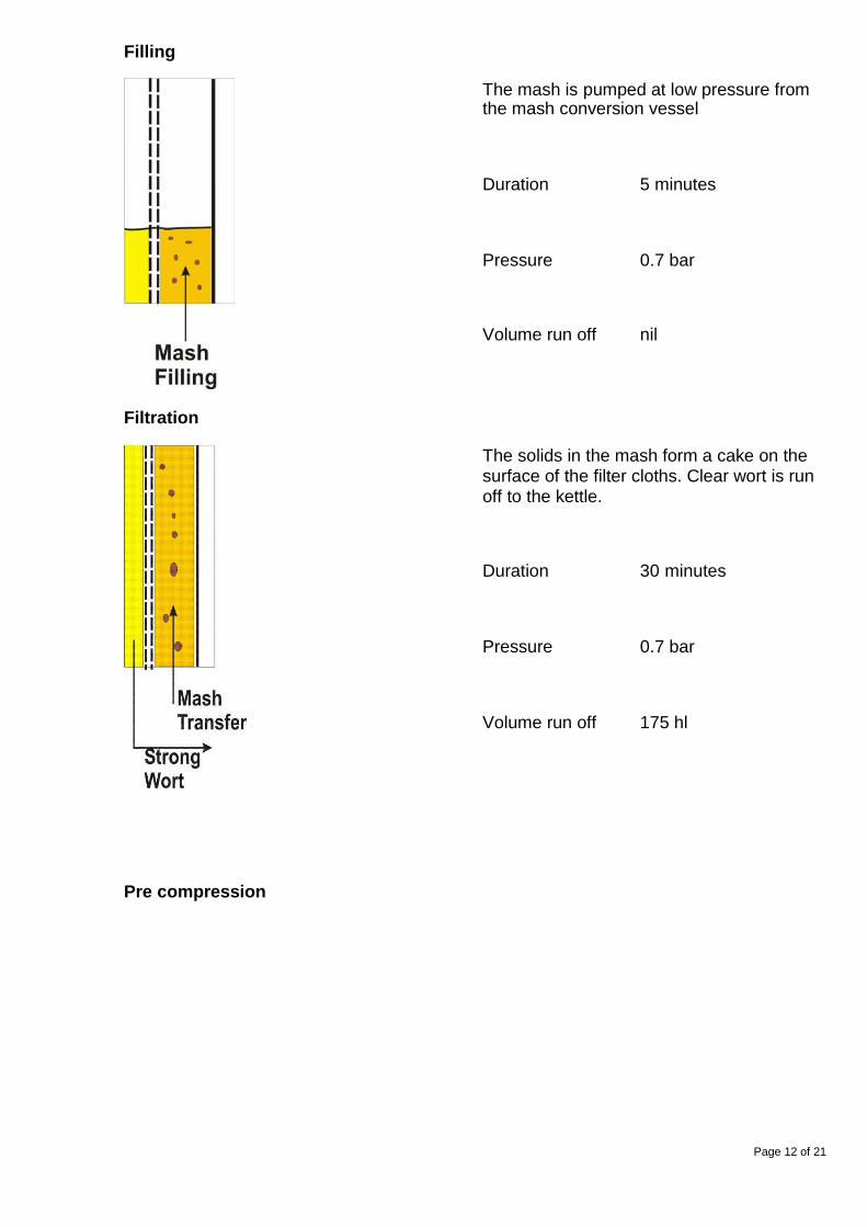
Filling
The mash is pumped at low pressure fromthe mash conversion vessel
Duration 5 minutes
Pressure 0.7 bar
Volume run off nil
Filtration
The solids in the mash form a cake on thesurface of the filter cloths. Clear wort is runoff to the kettle.
Duration 30 minutes
Pressure 0.7 bar
Volume run off 175 hl
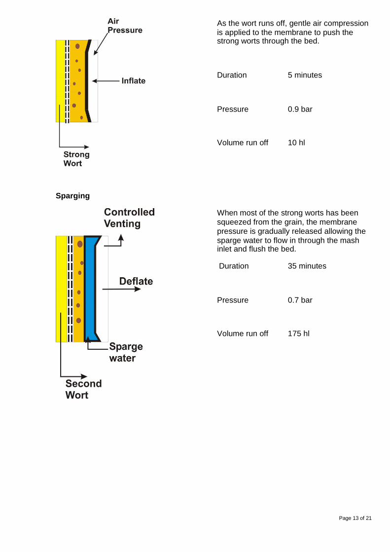
Pre compression
Page 13 of 21
As the wort runs off, gentle air compressionis applied to the membrane to push thestrong worts through the bed.
Duration 5 minutes
Pressure 0.9 bar
Volume run off 10 hl
Sparging
When most of the strong worts has beensqueezed from the grain, the membranepressure is gradually released allowing thesparge water to flow in through the mashinlet and flush the bed.
Duration 35 minutes
Pressure 0.7 bar
Volume run off 175 hl

Page 14 of 21
Final compression
When all the sparge has supplied themembrane is compressed at high pressureand the grains squeezed dry
Duration 10 minutes
Pressure 1 to 1.5 bar
Volume run off 20 hl
Cake discharge
Once all the extract has been squeezedfrom the grain, the pressure is released, thefilter is opened and the spent grains fall intothe grain hopper.
Duration 10 minutes
Pressure nil
Volume run off nil
Summary of typical mash filter cycle described above:
Event Duration mins Volume HI Pressure barFilling 5 0 0.7Filtration 30 175 0.7Pre compression 5 10 0.9Sparging 35 175 0.7Final Compression 10 20 1 to 1.5Cake discharge 10 0 0
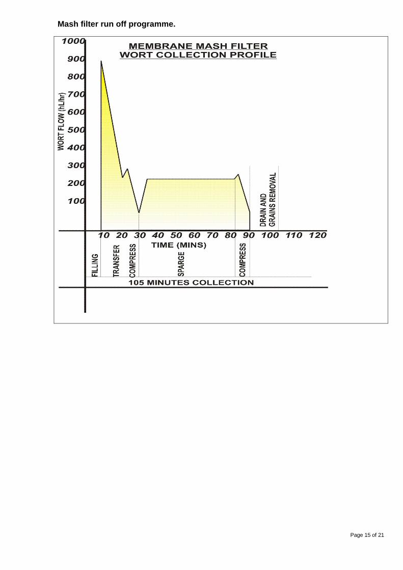
Page 15 of 21
Mash filter run off programme.

Page 16 of 21
2.4.6. The Isothermal Mash Tun
2.4.6.1. What does it consist of?
It is a combined conversion and wort separation vessel. It has also been discussed in themashing section.
Its physical construction is similar to a Lauter tun.
Older mash tuns will probably not have vents or CIP.
All cleaning and grain discharge will be by hand.
Isothermal Mash tuns require the coarsest grind.
It has no rakes to clear the bed.
It has the smallest filter surface area with the deepest bed of the three systems. Thecombination of these factors gives the mash tun the slowest filtration and poorer extractrecovery, but they can also produce the brightest worts. This performance is due to thecombined effects of the grind and the bed depth.
The poorer extract efficiency results from a coarse grind. This is partially offset by the useof a low rate of mashing water (2:1) and larger sparge volumes. This improves theleaching effect.
The flow rate of wort from a mash tun is usually manually controlled by the setting of runoff taps. These are adjusted to prevent pulling the bed down on to the plates. The mash ina mash tun floats on the wort, at least during the strong wort recovery.
During the initial run off flow rate is low to allow for the high viscosity of the wort. It alsoprevents the floating bed of mash being drawn down on to the false bottom of the vessel.The flow rate can be increased during sparging starts as the wort viscosity drops.
Mashing in is via a Steel’s masher. This is a rotating screw into which the grist drops.Water at the correct temperature is run into the screw at the same time. The screw“mashes” the grist which falls into the Mash Tun.

Page 17 of 21
Typical Mash tun cycle
Event DurationMashing in 20 minutesMash conversion stand 75 minutesRun off 185 - 330 minutesDrain down , Spent grains removal 20 minutesTotal turn around time 300-440 minutes
Excluding the time taken for the mash conversion, the mash tun is the slowest wortseparating system.
Mash tuns are well suited to their traditional use in producing wort from well modified malt.
They are the cheapest system in terms of capital outlay and are the simplest to operatewith little or no automation.
Mash tuns can only use a single temperature for mash conversion. Poor quality malts ormalts requiring a protein or glucanase stand cannot be handled. Mash tuns are also lesswell suited to modern large batch production. High brewhouse utilisation and extract is notpossible.

Page 18 of 21
2.4.7. Spent Grains
2.4.7.1. What are spent grains?
After wort separation is complete the waste material left behind is called spent grains.Spent grains are drained down and normally sold as cattle feed.
The removal of the grains depends on the systems:
2.4.7.2. Mash Tun
Thrown out by hand, or removed by a mechanical arm. The arm rotates over the falsebottom of the tun and pushes the grains towards outlet ports.
2.4.7.3. Lauter Tun
Normally mechanical. Done by turning the rakes so that they come flat on against the grainbed.
The space under the plates is normally rinsed prior to spent grain removal.
The spent grain flaps are opened in the base of the lauter tun ( they are set in and passthrough the false bottom). The rakes are rotated and slowly drop into the grain bed whereeach revolution forces a quantity of grain down the chute.
When the rakes reach the false bottom a special wiper-shoe (usually a rubber flap) wipesthe last bits of spent grain from the surface.
The spent grain falls into a holding bin below the lauter tun. It is normally blown withcompressed air through a screw conveyor and valve to a holding bin. Steam can be usedbut can give rise to excessive moisture
2.4.7.4. Mash Filter
The filter is opened up and the grains fall out, occasionally with sticky grains the clothsmay require scraping.
The installation should receive a full hot CIP at least once per week.
2.4.7.5. Grain disposal
The discharged grains are usually conveyed either by a screw conveyor or usingcompressed air to a storage silo, where they can be loaded into local transport forremoval.
The % solids of the grains is between 19 and 36% depending on wort extraction systemand drainage. If the grains cannot be taken away wet then it is necessary to dry them.After draining down, the grains may be passed through a decanter centrifuge to removeexcess moisture before being dried in a drum oven.
The spent grains are valuable sources of protein and carbohydrate and are normally soldas animal feed. If you sell spent grains it is probable that the purchaser will accept spenthop residues mixed in. Whirlpool trub and tank bottoms can enhance the protein content ofthe spent grain. However do not add yeast to the mixture without prior consultation withthe purchaser as cattle in particular cannot tolerate high levels of yeast.

Page 19 of 21
2.4.7.6. Q.C.
Analysis of the spent grain can provide valuable information about the brewhouse process.Visual examination should show no whole corns and the husks should be essentiallyunbroken. Laboratory analysis can also indicate retained extract, which may be improvedby refining lautering techniques.
2.4.8. Requirements & Quality of mash separation
1. The following table summarises the different requirements of each system.
Mash Tun Lauter Tun Mash Filter
Milling system 4 roller dry 6 roller or wet mills hammer mills
Grist type Coarse Medium/fine very fine
Mashing andseparating vessels
One vessel Two vessels Two vessels
Mash water to gristratio l/kg
2 to 2.5 3 to 3.5 2.9
Sparge water l/kg 4.5 3.8 2.4
Total water to gristl/kg
7 6.8 5.3
Filtration aream2/tonne
2.5 4.5 35
Grain bed depthmm
1,000 500 50
Bed loading kg/m2 400 200 28
Filtration rate 1 litre/sq m /min 0.6 litre/sq m /min 20 litre/sq m /min
Brews process perday
6 8 to 10 12
Space for 1000 hlbrew length
250 sq m 180 sq m 50 sq m

Page 20 of 21
2. The following table summarises the different quality results of each system.
Parameter Mash Tun Lauter Tuntraditional
Lauter Tunmodern
Modern MashFilter
Initial wort haze(EBC)
10 >20 >10 >20
Average worthaze (EBC)
4 15 5 - 8 < 5
First wort gravity 20 22.5 24 25
Kettle gravity 15 16 17.5 19
Total lipid ( ppm) 2 23 18 17
Solids Imhoffcone (ml/litre)
<8 >10 <12 <5
Polyphenol(ppm)
165 180 195 195
Extractefficiency. (%Lab)
97 97 98 101
Spent grains (%solids)
19 21 24 36
3. Summary of the process differences between a mash filter and lauter tun.
Property Mash Filter Lauter Tun
Extract efficiency Circa 102 % Circa 97.5 %
Turn around Circa 2 hours –
12 brews/day
Circa 3 - 4 hours –
8 - 10 brews/day
Flexibility Full charge + 5 % - 10% Full charge ± 35 %
Operation No underlet
Easier run off
More problems with runoff
Size (10 tonnes) Small 3 x 12 m 8 m diameter
Maintenance Low - few moving parts Higher – more movingparts
Spent grains Dry – moisture < 65 % Wet – moisture > 78 %

Page 21 of 21
2.4.9. Brewhouse extract efficiency
2.4.9.1. Calculation of brewhouse extract efficiency
The Brewer is anxious to recover as much of the sugar (extract) from the brewingmaterials (goods) as possible. The yield or extract efficiency is calculated by comparingthe extract recovered in the wort compared with the laboratory extract of the same brewingmaterial.
Extract recovered in the wort is expressed as the Original Gravity multiplied by the volumecollected in litres. Laboratory extract is based on a laboratory mash of the materials as a10% solution (see analytical methods).
The extract recovered is measured in the fermentation vessel as:
500 hl of wort collected at an original gravity of 120 PlatoThis is equivalent to = 500 x 100 x12 = 6000000 Plato
Grist supplied:Standard malt charge = 6505 kg 80%Coloured malt charge = 459 kg 66.7%Sugar = 703 kg 85.3%Extract supplied using EBC methods:Standard malt charge = 6505 kg x 80% = 520400Coloured malt charge = 459 kg x 66.7% = 30615.3Sugar = 703 kg x 85.3% = 59965.9
Total extract supplied = 6109810 Plato
Extract yield = (610981.2 –600000)/610981.2) x 100
= 98.2%
2.