
_02 Abb Pm Inst Book-tank Density Mtr
64
SF 6 Circuit Breakers Type PMR with Tank Mounted Density Monitor 242 PMR with Tank Mounted Density Monitor Publication No. 526P132-006 ' Installation & Maintenance ' ABB NOTE: For Installation and Maintenance information regarding the 242 PMR Power Circuit Breaker equipped with Cabinet-Mounted Density Monitor, please refer to Publication No. 526P121.
-
Upload
hvinstructor -
Category
Documents
-
view
518 -
download
1
Transcript of _02 Abb Pm Inst Book-tank Density Mtr

SF6 Circuit Breakers
Type PMRwith Tank Mounted Density Monitor
242 PMRwith Tank Mounted Density Monitor
Publication No. 526P132-006© Installation & Maintenance©
ABB
NOTE: For Installation and Maintenance informationregarding the 242 PMR Power Circuit Breakerequipped with Cabinet-Mounted Density Monitor,please refer to Publication No. 526P121.


526P132-006242 PMR with Tank Mounted Density Monitor - Installation & Maintenance©
Contents
Contents1. Breaker Description 61.1 Bushings and Current Transformers 71.2 Interrupters, Bellcranks, and Interphase
Linkage 71.3 Mechanism 81.4 SF6 Gas System and Safety Features 81.5 Control Cabinet 81.5.1 Optional Electrical Control Packages 81.6 Circuits and Components 91.6.1 AC Circuits (Charging Motor & Heaters) 91.6.2 DC Circuits 91.6.3 Operations Counter 91.7 Breaker Operation 9
2. Installation 102.1 Receiving and Handling the Breaker 102.1.1 Moving the Breaker 112.2 Storing the Circuit Breaker and Spare Parts 112.2.1 Long-term Storage Instructions 122.2.2 Parts Storage Instructions 122.3 Installing the 242 PMR Circuit Breaker 132.3.1 Installing the Bushing Top Terminal 142.3.2 Slow Close Operation 14
3. SF6 Gas Reclaiming and Filling 153.1 Reclaiming SF6 Gas from a Pole Unit 163.2 Filling the Circuit Breaker with SF6 Gas 173.2.1 Filling a Pole Units from a Gas Cylinder 173.2.2 Filling Pole Units Using a Gas Service Unit 193.2.2.1 Filling Unopened Pole Units - Initial Filling on
Installation (Typically for Domestic Breakers) 193.2.2.2 Evacuating and Refilling Pole Units 203.3 Installing the Portable In-Line Filter 213.4 Replacing Desiccant in the Portable In-Line
Filter 213.5 Isolating a Pole Unit from the Gas System 21
4. Testing 224.1 Pole Resistance Measurement 224.2 Moisture Measurement of the SF6 Gas 224.2.1 Measuring the Moisture 224.3 Leak Checking 224.4 Operational and Timing Tests 224.4.1 Operational Tests 224.5 Check the Oil Level in the Mechanism 234.6 Density Monitor Set Point Tests 234.6.1 Tests Using Pole Unit Gas 234.6.2 Tests Using a Separate Gas Source 24
5. Maintenance 255.1 Maintenance Tips 255.1.1 Applying Loctite 255.1.2 Seals 275.1.3 Flange Corrosion Protection 27
US Standard Torque Table 2a 27Metric Torque Table 2b 28
5.1.4 Treatment of Silverplating 285.2 Pole Unit Maintenance Procedures 295.2.1 Removing the Rear Tank Cover and Cleaning
the Pole Tank 29
5.2.2 Replacing the Rupture Disk 305.2.3 Replacing the Desiccant Bag 315.2.4 Re-installing the Rear Tank Cover Assembly 325.2.5 Isolating a Pole Unit 325.2.5.1 De-Coupling the Interphase Linkages
(Removing the Interphase Shafts) 325.2.5.2 Synchronizing the Interrupter Contacts 335.2.5.3 Setting the Guide Piston Length 335.2.5.4 Re-Coupling the Interphase Linkages
(Re-installing the Interphase Shafts) 335.2.6 Rebuilding the Bellcrank Assembly 345.2.6.1 Rebuilding the Left or Right Bellcrank Assembly 345.2.6.2 Rebuilding the Center Bellcrank Assembly 355.2.7 Removing/Installing Current Transformers 355.2.8 SF6 Gas Density Monitor and Calibration 37
6. Safe Handling of SF6 396.1 Equipment Used to Handle SF6 Decomposition
Products 396.1.1 Protective Gear 396.2 SF6 Gas Handling Safety and Purging Practices 396.3 Removing SF6 Decomposition Products 406.4 Disposing of Decomposition Products 406.4.1 Removing SF6 Gas Residue from Tools and
Equipment 41
FiguresFigure 1Lifting the Breaker 42Figure 2Control Cabinet 60000 43Figure 3SF6 Gas Density Monitor Calibration Curve forPressure vs. Temperature 44Figure 4SF6 Gas Filling and Density Monitor Calibration Chart 45Figure 5Gas Charging Arrangement 46Figure 6SF6 Gas Schematic 47Figure 7Tank Mounted SF6 Gas Density Monitor 60441 48Figure 8Terminal Pad 20311 49Figure 9Pole Unit Assembly (Left, Center, or Right) 50/51Figure 10Rupture Disk Cover Assembly 52Figure 11SF6 Gas System Disconnect Gas Valve 53Figure 12Linkage (Front View) 54Figure 13Side View of Crank, Linkage, and Pullrod 55
526P132-006242 PMR with Tank Mounted Density Monitor - Installation & Maintenance©
Contents
Figure 14Manual Open/Close Tool T13451 56Figure 15242 PMR Bellcrank Assemblies (without Valves) 57Figure 16Shaft Seal Assembly 10153 58Figure 17Bellcrank Linkage to Interrupter Unit 59Figure 18Current Transformer 70000 60Figure 19Tank Heater Assembly 10055 61Figure 20Guide Piston Dimension for HMB Hydraulic Mechanisms 62Figure 21Density Monitor Installation to each Tank 63

Notice 1
Based on our own experience, you will obtain the best possible operational reliability by following the recommendationsgiven in these instructions. The data contained herein purports solely to describe the product, and it is not a warranty ofperformance or characteristics. It is with the best interests of our customers in mind that we constantly strive to improveour products and keep them abreast of advances in technology. This may lead to discrepancies between a product andthese instructions.
Notice 2
Within the scope of these instructions, it is impossible to take into account every eventuality which may arise with technicalequipment in service. Please consult our local salesman in the event of any irregularities, especially if not referred to herein.
Notice 3
We expressly decline liability for damages resulting from any incorrect operation or wrong handling of our equipment, evenif these instructions contain no specific indication in this respect. We stress the fact that only genuine spare parts shouldbe used for replacements.
Notice 4
This publication is a copyrighted work. Therefore, it is not permissible to disclose, reprint, copy, or reproduce any partof these instructions without express written permission from ABB.
These instructions do not purport to cover all details or variations in equipment nor to provide for every possible contingencyto be met in connection with installation, operation, or maintenance. Should further information be desired or should particularproblems arise which are not covered sufficiently for the purchaser�s purposes, the matter should be referred to ABB Inc.
©Copyright 2003, 2005, ABB All rights reserved.
526P132-006242 PMR with Tank Mounted Density Monitor - Installation & Maintenance©
Notes

526P132-006242 PMR with Tank Mounted Density Monitor - Installation & Maintenance©
Page 6
August 2005
Installation & Maintenance
Instructions in this module pertain to receiving, handling,storing, installing, commissioning, and maintaining the242 PMR circuit breaker.
Important: As a convenience and to prevent any over-sights, tabular checklists which include all ofthe tests and items to check during installa-tion, commissioning, and maintenance areprovided in the modules listed below. Toensure proper operation, ABB recommendscompleting the respective checklists wheninstalling, commissioning and maintainingthe 242 PMR.
Installation and Commissioning Checklistin the Checklists module
5-Year Maintenance Checklists in theChecklists module
Checklist in the Mechanism module
Timing Checklistin the Customer Data module.
1. Breaker Description
The 242 PMR circuit breaker is a multiple-tank, sulfurhexafluoride (SF6) puffer-type circuit breaker manufacturedby ABB. This high speed, state-of-the-art circuit breakerensures reliable switching performance and fault interrup-ting capability.
The 242 PMR circuit breaker (Illustration 1) consists ofseveral major components:
� Three pole units;� Six entrance bushings;� Bushing-type current transformers;� Three interrupter units;� Interphase linkages;� Mechanism;� Control cabinet.
Illustration 1242 PMR Circuit Breaker
EntranceBushings
CurrentTransformers
InterphaseLinkage
Pole Unit
Control Cabinet
Side ViewFront View

526P132-006242 PMR with Tank Mounted Density Monitor - Installation & Maintenance©
Page 7
August 2005
The three pole units are coupled to a single operatingmechanism through an interphase linkage assembly. Thepole tank ("U-stamped" ASME pressure vessel) is made upof two halves bolted together in the center and sealed viaan O-ring in the center and on each tank end. A nickelreverse buckling rupture disk is fitted to the bottom of eachtank to protect against excess pressure build-up whichcould otherwise lead to catastrophic failure of pressurizedcomponents. Two bushings are situated at obtuse angleson each pole tank. The bushings are equipped with topterminals for connecting to the high voltage line or bus.
1.1 Bushings and Current Transformers
The bushings are an integral part of the breaker and arespecifically designed to connect to the high voltage line orbus and carry high voltage power to the interrupter whileproviding line-to-ground insulation.
Two plug-in type, entrance bushings are installed at slightangles on top of each pole tank. Top and bottom aluminumflanges are permanently cemented onto the insulators.The bottom flange of the bushing has an adapter platewhich keeps the throat shield fixed in position within thebushing insulator.
The bushings are hollow, high strength vessels filled withSF6 gas which acts as the insulating medium. A conductorassembly (thru rod) fits to the top flange of the bushing andextends through the hollow center of the bushing andattaches to the interrupter.
Bushing-type current transformers (CTs), mounted inweatherproof aluminum protective covers, surround thepockets below the bushings. Each phase of the 242 PMRcircuit breaker can be equipped with many combinationsof CTs or linear couplers as per customer specifications.CT secondary leads are installed in conduits extendingfrom each CT housing and terminating onto shorting typeterminal blocks in the control cabinet. A nameplate on theinside of the cabinet door indicates the location, accuracy,and ratio of the current transformers.
1.2 Interrupters, Bellcranks, and InterphaseLinkage
The type SD interrupter is a single pressure, single break,sulfur hexafluoride (SF6) gas puffer-type unit capable ofinterrupting terminal faults and 90 percent short-line faultsup to ratings listed on the front cover of this manual. Eachinterrupter consists of a moving contact assembly and amain contact finger assembly. Both assemblies contain amain contact and an arcing contact.
Under normal conditions, the main contacts carry continu-ous current through the breaker. During interruption, themain contacts part first. Shortly afterward, the arcingcontacts part, an arc propagates between them and thecurrent eventually is interrupted. Because the arc is inter-rupted at the arcing contacts, the integrity of the maincurrent carrying contacts is preserved.
The interrupting components are mounted by an insulatingsupport tube situated within the grounded cylindrical tankof each pole unit. In the OPEN position, the moving andmain contact finger assemblies are isolated from eachother by an insulating interrupter tube. The moving con-tacts are driven by the bellcrank assembly, which convertsthe vertical motion of the operating mechanism to thehorizontal motion of the interrupter contacts. An insulatingpullrod connects the bellcrank assembly to the movingcontacts.
Three bellcrank assemblies (one for each pole unit) aretied together by the two interphase shafts (left and right10204 (Fig. 12)). The interphase shafts are coupled to themechanism pullrod 10207 through a crank at the centerpole unit. Working with the mechanism, the bellcrankassemblies open and close the interrupters in the respec-tive pole units. The crank at the center pole converts thevertical motion of the mechanism pullrod to the rotationalmotion of the interphase shafts. The bellcrank assembliesthen convert this rotational motion to the horizontal motionof the interrupters.
The three pole units are interconnected by an interphaselinkage assembly. The interphase linkage includes thebellcranks and all components that join the individual poleunits into a single breaker unit.

526P132-006242 PMR with Tank Mounted Density Monitor - Installation & Maintenance©
Page 8
August 2005
1.3 Mechanism
The HMB-1.8 hydraulic operating mechanism for the 242PMR circuit breaker is housed within the control cabinet.The HMB mechanism is driven completely hydraulically. Astack of disc springs serves as an energy storage system.During both opening and closing operations, hydraulic oildrives the piston/pullrod of the mechanism, consumingenergy from the stack of disc springs. There is no directmechanical link between the spring stack and the piston/pullrod. The storage springs are charged using a hydraulicpump; this stored energy provides the driving force forhydraulic oil as the breaker is opened and closed.
1.4 SF6 Gas System and Safety Features
Pressurized sulfur hexafluoride (SF6) gas surrounds the inter-rupter and fills the pole tanks and hollow entrance bushings.
Sulfur hexafluoride gas is chemically inert and non-flam-mable. This gas has a high dielectric strength and thermalproperties conducive for insulating high voltage and quench-ing electrical arcs which is why it is used in these types ofcircuit breakers. Maintaining a proper gas density in thepole units is essential for optimum breaker operation.
The pole unit gas pressure and ambient temperature aremonitored to derive the gas density. Some breaker modelshave an SF6 gas density monitor 60441 (Figs. 6 and 21)mounted onto each pole. A quick disconnect valve 10154(Fig. 11a/b) mounted at each bellcrank conveniently allowsfor gas filling and reclaiming. The temperature-compen-sated density gauge mounted off of the gas valve is re-moved for gas servicing.
Other breaker models use a gas manifold 10213 (Figs. 6and 11) which links the three pole units into a single gasdensity monitoring system. The gas density monitor 60441is mounted onto the left pole. A quick disconnect fitting 10154at each bellcrank assembly conveniently allows the indi-vidual pole units to be isolated from the gas manifold. TheSF6 gas can be reclaimed from one, two, or all three poleunits as desired by loosening the nut on the quick discon-nect fitting where the gas is not to be reclaimed without losingany SF6 gas and then opening the sample valve 60007 (Fig.5) in the control cabinet. This design provision is a greatadvantage when performing pole unit maintenance.
The SF6 gas density monitoring system compensates forpressure changes due to temperature variations and pro-vides alarm and lock-out functions only if low gas densityproblems exist. Maintaining a proper gas density is criticalto ensure the dielectric integrity of the pole unit.
A reverse buckling rupture disk is fitted to the bottom of eachpole tank. This disk protects against excess pressurebuild-up which could otherwise lead to catastrophic failureof pressurized components. If the tank pressure exceedsthe burst pressure listed on its nameplate (well below thehydrostatic test pressures of all other pressurized compo-nents), the disk will rupture directing the exhausting gasdownward, under the tank and away from personnel.
In compliance with the ASME Pressure Vessel Code, thepole tanks are "U-stamped."
1.5 Control Cabinet
The control cabinet is mounted to the steel structural frameof the circuit breaker. Field wiring enters the control cabinetthrough a panel at the base of the cabinet and is terminatedon the appropriate terminal blocks. The breaker controlcircuitry is wired and tested at the factory. If required, thecircuit breaker also can be fitted with a second controlcabinet mounted to the rear of the structural frame.
Components housed in the cabinet include:
� Operating mechanism;� CT shorting terminal blocks;� Anti-condensation heaters;� Control relays;� Terminals for field connections;� Auxiliary switches;� A mechanical operations counter which keeps track
of the number of trip operations;� Circuit breaker control panel and/or special optional
control packages, e.g. Synchronous Control Unit(SCU), Condition Monitoring Unit (CMU), or BreakerControl Unit (BCU). (Refer to section 1.5.1.)
1.5.1 Optional Electrical Control Packages
If the breaker is equipped with a Synchronous Control Unit(SCU), this microprocessor controls the breaker for syn-chronous switching functions in independent pole operat-ing applications. The SCU allows for either synchronousclosing or opening of contacts. Synchronous closingimproves power quality by reducing transients. This reduc-tion occurs when each phase of the breaker closes on ornear voltage zero for capacitive switching or at peak voltagefor inductive switching applications. Through synchronousopening, the SCU can optimize arcing times of the inter-rupters, thereby improving interrupter performance andextending contact life. The SCU monitors system voltageand current through potential transformers and currenttransformers. If the breaker is equipped with an SCU, aseparate instruction booklet for this device will be provided.(The SCU is automatically incorporated on 242 PMRI-typecircuit breakers. These breakers are independent pole-operated breakers.)
If the breaker is equipped with a condition monitoring unit(CMU) such as the PowerIT Circuit Breaker Sentinel, thisunit monitors interrupter nozzle and contact wear, andtravel characteristics of breaker timing. The unit will indi-cate any problems with the interrupter and timing. Theadvantage of this electrical control/monitoring device isthat it precludes routine unnecessary maintenance andindicates when maintenance is required as well as thecondition of the interrupter nozzles and contacts. If yourbreaker is equipped with a CMU, a software interface andan instruction manual will be provided.

526P132-006242 PMR with Tank Mounted Density Monitor - Installation & Maintenance©
Page 9
August 2005
1.6 Circuits and Components
1.6.1 AC Circuits (Charging Motor & Heaters)
AC circuits include:
� Charging motor� Control cabinet heaters� Tank heaters (optional).
The charging motor controls are designed to automaticallymaintain the stored spring energy of the mechanism. Aspring limit switch closes to pick up a contactor supplyingthe charging motor. When the operating energy is restoredto its normal level, the limit switch contact opens to turn thecharging motor off.
Notice: The charging motors can, if specified, beoperated on DC power or AC power with DCbackup as options.
Anti-condensation heaters are located in the control cabi-net. The normal heater circuit provides for 150 Watts of heatenergized continuously (H1 and H2), with another 150Watts thermostatically controlled (H3 and H4).
Notice: The anti-condensation heater circuit is to beenergized at all times, regardless of the am-bient temperature.
These heaters are series connected for half voltage (1/4wattage) operation on each heating element to ensuretrouble-free service for many years.
In operating conditions where ambient temperatures be-low -22°F (-30°C) can occur, the breaker pole tanks mustbe equipped with thermostatically-controlled tank heaters10055 (Fig. 19) to prevent the SF6 gas from liquefying. Thethermostat operates at -10°F (-23°C). Refer to Figure 19 toview tank heater assemblies installed on a pole tank.
The thermostat for the tank heaters can be either locatedoutside of the control cabinet or mounted on the inside wallof the control cabinet, covered with insulation. In eithercase, the thermostat must be situated in a place at ambienttemperature.
1.6.2 DC Circuits
The DC control system converts remote operating signalsinto breaker operations. This control system also monitorsthe operational status of the breaker (SF6 pressure, mecha-nism energy, breaker position, etc.) and automaticallyperforms TRIP BLOCK (or AUTO TRIP) and CLOSE BLOCKfunctions when necessary.
1.6.3 Operations Counter
The breaker is furnished with a mechanical operationscounter which is located in the control cabinet, and visiblethrough a view port. This counter keeps track of the numberof trip operations. (Optional electric operations counterscan be furnished upon request and, likewise, would belocated in the main control cabinet.)
1.7 Breaker Operation
Under normal conditions, pressurized SF6 gas surroundsthe interrupter units and fills the hollow entrance bushingswithin each pole unit. The gas is both an insulating and arcquenching medium.
Current from the bushing conductors flows to the main andmoving contact assemblies in the interrupters. Duringinterruption, the mechanism opens, providing the me-chanical force required to initiate interruption. This motionis transferred to rotational motion at the interphase linkage.The bellcrank assembly, attached to the interrupter by aninsulated pullrod, converts the rotational motion from theinterphase linkage to the required horizontal force to open(and close) the interrupter contacts.
Consequently, the main contacts within the interrupter partfirst, then the moving contacts part. An arc propagatesbetween the contacts and is eventually extinguished by thecooling, puffer effect of the SF6 gas circulating through theinterrupter to attain successful interruption.
All ABB circuit breakers are in compliance with the latestapplicable IEC, NEMA, and ANSI C37 standards for outdoorhigh voltage circuit breakers.
Notice: The breaker should not be subjected to du-ties in excess of nameplate ratings. Thenameplate is located on the inside of thecontrol cabinet door and indicates the loca-tion, accuracy, and ratio of the current trans-formers.

526P132-006242 PMR with Tank Mounted Density Monitor - Installation & Maintenance©
Page 10
August 2005
2. Installation
The 242 PMR breaker is factory-tested and shipped readyfor easy and quick installation. After the breaker is installed,a quick verification of a few parameters is all that is requiredbefore placing the breaker into service.
The Customer Data module serves as a customized refer-ence guide unique for your applications. The nameplate onthe inside of the control cabinet door of the breaker indicatesthe location, accuracy, and ratio of the current transformers.
Notice: The 242 PMR circuit breaker should not besubjected to duties in excess of nameplate rat-ings unless agreed upon at the time of purchase.
To prevent any oversights, follow the procedures in thissection and complete the appropriate checklists in theChecklists module, Mechanism module, and CustomerData module to ensure proper installation and operation.
All personnel designated to install this breaker mustreview section 6 in this module.
DO NOT WEAR POLYESTER, ACETATE, NYLON, OR RAYONCLOTHING (SUCH AS SHINY-TYPE SKI JACKETS ANDWIND BREAKERS WHICH USUALLY CONTAIN NYLON)AROUND LIVE ELECTRICAL EQUIPMENT.
2.1 Receiving and Handling the Breaker
Unless shipping regulations or customers specify other-wise, domestic breakers shipped within the continentalUnited States are completely assembled and contain apartial charge (5 psig (0.03 MPa)) of pure SF6 gas. Thesebreakers just are topped off with more SF6 gas duringinstallation. Whereas, breakers shipped overseas arecharged to 5 psig (0.03 MPa) with dry nitrogen gas and thebushings usually are not installed. When the overseasbreaker is installed, the bushings will need to be installed(as per the Bushings module), a new desiccant bag 10008(Fig. 9) will need to be installed in each pole tank and thepole units will need to be closed and evacuated beforefilling the breaker with SF6 gas as per sections 5.2.3, 5.2.4,and 3.2.2.2 respectively.
When the shipped unit(s) arrive(s) at the destination, checkthe material received against the packing list immediately.A service kit and any special tools required for this breakershould also be included with the breaker shipment. Referto the Customer Data module for a list of required andoptional special tools, materials, and vendors.
Inspect the pole tank and flanges for damage. Inspect thebushing insulators for cracks, nicks, or damage. If the poleunits are de-pressurized, check for leaks (section 4.3).Contact ABB if there are any problems with the shipment.Be certain that all parts have been received to avoid delaysin installation. If the breaker is found to be damaged or issuspected of being damaged, file a claim immediately withthe transportation company. Next, notify the local ABBrepresentative of shortages or damaged equipment.
Notice: If the bushings are shipped separately, such asfor overseas shipment, refer to the shippingassembly drawing for special instructions onreceiving, handling, and lifting the shipping units.
The breaker either can be installed (section 2.3) or stored(section 2.2). To transport a fully assembled breaker, referto section 2.1.1.
DANGERDo not energize, test, or operate thebreaker until it is filled with SF6 gas.
x
RUOOTECITON:SREMOTSUCDEULAV
x
lairetamgnippihsWOLLEYynanruteresaelP,srevocgnippihsdetniap-wolleygnidulcni(
ruoytcetorpotdesu).cte,secarb,stekcarb.wolebdetsilsserddagnippihsehtotrekaerb
xdedivorpsahBBA,ecneinevnocruoyroF
.tsocontaesehtx
.deriuqersinoitazirohtuanruteroNdetinUcitsemodehtedistuosremotsuC
.ecitonsihtdragersidyamsetatSx
:sserddAnruteR.cnI,baF-asreV
kraPlairtsudnIyttaeBdaoRyttaeB416
64151AP,elliveornoMx
8361-658)214(:xaF;1787-658)214(:enohPx
TCELLOCslairetamlladnesesaelP:sreirracgniwollofehtgnisu
REIRRAC #TNUOCCA
dnalloHFSU 58455
thgierFwolleY)#tnuoccAoN(
ottcellocthgierF.cnIBBA
)XCC(yawnoC 800NPXNRBFA
FBA 688710
setsE 5188352
yawdaoR 4200-602.noitacilbupfoemitfosaetaruccasinoitamrofnitcatnoC
.cnIBBAtaevitatneserperselasruoytcatnocesaelP.tcerrocniebnoitamrofnievobaehtdluohs
setatSdetinUcitsemodehtedistuosremotsuC.ecitonsihtdragersidyam
t x:nt
BBA B

526P132-006242 PMR with Tank Mounted Density Monitor - Installation & Maintenance©
Page 11
August 2005
2.2 Storing the Circuit Breaker and Spare Parts
The breaker can be stored indoors or outdoors. When abreaker is to be stored, maintain a slight positive pressureof dry SF6 gas (5 psig (0.03 MPa)) to prevent corrosion ofthe internal components and absorption of moisture.
Notice: Breakers shipped with bushings installed(primarily in North America) contain a partialcharge 5 psig (0.03 MPa) of pure SF6 gas andjust are topped off with more SF6 gas duringinstallation. Whereas, breakers shipped with-out bushings are charged to 5 psig (0.03 MPa)with dry nitrogen gas. The dry nitrogen gas isalso acceptable for storage. A note should beplaced on the breaker indicating that it ispartially charged with dry nitrogen gas. Whenthis breaker is installed, the pole units willneed to be evacuated before filling the breakerwith SF6 gas as per section 3.2.2.2.
Important: If the fully assembled breaker is to be storedlonger than 1 month, refer to section 2.2.1 andprotect the operating mechanism and controlcabinet from moisture and corrosion by clos-ing the housing and energizing the anti-con-densation heaters. A desiccant bag 10008(Fig. 9) should already be installed in eachpole tank.
Notice: If the pole units have been opened on abreaker which is to be stored, the openedpole units must be closed, evacuated, andfilled to a positive pressure with dry, SF6 gasto approximately 5 psig (0.03 MPa). Refer tosection 3.2.2.2 in this module for instructionson evacuating and refilling a pole unit whichhas been opened.
Sufficient recommended spare parts and renewal partsshould be carried in stock to enable prompt replacementof worn or damaged parts and minimize down-time. Re-newal parts are consumable parts such as desiccantbags, motor brushes, etc. that most likely will need to bereplaced. Spare parts are items which may or may not wearout over time. Refer to the Spare Parts module for a listingof parts to keep in stock. Refer to section 2.2.2 in thismodule for instructions on storing parts.
In cases where product improvement designs may causea new part to not be identical to the original part, restassured that the new part will definitely be interchangeablewith the original part.
As for standard hardware items, it is suggested that theseitems be purchased locally to save time and expense. ABBwill provide spare part hardware when it is of a specialnature or where standard hardware is specifically re-quested.
2.1.1 Moving the Breaker
The breaker should be transported on an air-ride sus-pension trailer to minimize the effects of shipping stress-es. ABB recommends that the pole tanks be outfittedwith 5 g rated, MAG 2000 impact monitors and the framelegs be securely strapped to the trailer bed as a precau-tion against shipping stresses. Check the MAG impactmonitor once the breaker arrives at its destination todetermine if the breaker experienced intense shippingstresses. If the breaker experiences heavy stress,contact ABB on how to proceed.
The lifting arrangement for the fully assembled breaker(with bushings installed) is shown in Figure 1.
To move the breaker:
1. Be sure that the breaker is in the OPEN position andthat the mechanism springs are completely discharged.
2. The SF6 gas pressure in the pole units should beapproximately 5 psig (0.03 MPa) before moving thebreaker. (If a fully assembled breaker that has beenin service is to be moved, gas needs to be reclaimedto reduce the pressure. Refer to section 3.1.)
DANGERNever move or install a breaker that isfully pressurized with SF6 gas.
3. Lift the breaker as shown in Figure 1.
Notice: ALWAYS LIFT THE DEPRESSURIZEDBREAKER BY THE LIFTING LUGS ON THEFRAME FOLLOWING THE RIGGING AR-RANGEMENT IN FIGURE 1 AND USING ACRANE WITH A LIFTING CAPACITY OF ATLEAST 7 TONS.
4. Remove the leg bolts and retract the extension legsinto the breaker frame and fasten the legs into theretracted position using the leg bolts.
5. Mount the breaker to wooden skids at the foot pads tokeep the breaker from tipping over during transport.
6. Secure the breaker with straps during transport. Becareful not to damage the entrance bushings.
If possible, transport the breaker on an air ride cushiontruck to reduce shipping stresses placed on the breaker.

526P132-006242 PMR with Tank Mounted Density Monitor - Installation & Maintenance©
Page 12
August 2005
When ordering spare parts, refer to the breaker nameplateand this manual to properly identify the parts:
� Order number see orderingdocumentation
� Code number of type see identification plate� Serial number see identification plate� Publication number see cover page� Part number see spare parts list
Five-digit index part numbers in this manual refer to breakercomponents. ABB Parts and Service will correlate the indexpart number in this manual to a unique, nine-digit partnumber specific to your breaker. (The index part numberin this manual is merely a reference aid.)
Hardware items such as nuts and washers have a nine-digit actual part number prefixed with the letter "H."
Index part numbers for special tools used to handle andmaintain these circuit breakers are prefixed with the letterT followed by a five-digit number. For example, the indexpart number for the travel recorder kit is 13435.
2.2.1 Long-term Storage Instructions
Long-term storage means 1-month or longer. Although thebreaker can be stored indoors or outdoors, indoors undercover is preferred. If the pole units are to be storedoutdoors, follow the precautions listed below.
If a breaker is not to be put in service after it is received,continue to maintain the slight positive pressure of dry, SF6gas (5 psig (0.03 MPa)) (or dry nitrogen gas if it is anoverseas shipment). For breakers with dry nitrogen gas,place a note on the pole units indicating that the units arepartially charged with dry nitrogen gas. Dry gas (SF6 ornitrogen) prevents corrosion of the internal componentsand absorption of moisture.
Important: Protect the operating mechanism and controlcabinet from moisture and corrosion by clos-ing the housing and energizing the anti-con-densation heaters in the control cabinet.
Wearing gloves, remove the special foam-type Hoffman Rust Inhibitor from the wrapperand install it under the cabinet roof directlyover the operating mechanism to preventrusting. Avoid prolonged breathing of theinhibitor vapors and avoid contact with yourskin or eyes. Change this rust inhibitor every12 months while the pole unit is in storage.
The rust inhibitor can be purchased from:
Hoffman Engineering Co.Type A-HCI-10E or similar(612)-421-2240FAX (612)-421-1556
Notice: If the pole units have been opened on abreaker which is to be stored, the openedpole units must be evacuated and filled to apositive pressure with dry, SF6 gas to approxi-mately 5 psig (0.03 MPa). Refer to section3.2.2.2 in this module for instructions on evacu-ating and refilling a pole unit which has beenopened.
2.2.2 Parts Storage Instructions
Keep spare parts in a clean, dry room to minimize thepossibility of moisture and corrosion damage. Preservespare parts as follows while they are in storage:
1. Carefully handle parts sealed in plastic bags; avoidripping the bag; (plastic bags must be intact); onlyremove the bag when you are ready to install the part.
2. Store rubber parts in a cool, dry place; protect themfrom moisture, light, sun, and rain.
3. Store rupture disks 10017 (Fig. 10) in individual boxesas received from the supplier. Avoid touching orbumping the domed center. Never set the disk downon the domed center side and never install a rupturedisk that is dented or scratched.
4. Unsuitable storage causes accelerated aging of seals.The following rules permit spare seals to be stored forseveral years without deterioration:
� Maintain a storage temperature between 40°F and70°F (4°C and 21°C).
� Protect the storage area from water condensation orhigh humidity,
� Maintain a closed atmosphere in a suitable packingto reduce the oxidizing effects of air.
� Store the seals away from effects of ozone or equip-ment or machines which produce sparks or arcs.
� Avoid contamination with fluids, oils, and fats. Avoidcontact with metals (copper, iron, manganese andtheir alloys), rubber of other grades, and plastics.
� Store seals (O-rings) flat with no stress, pressure,deformation, or bending.
526P132-006242 PMR with Tank Mounted Density Monitor - Installation & Maintenance©
Page 13
August 2005
2.3 Installing the 242 PMR Circuit Breaker
Proceed with extreme caution because installation ofteninvolves working near energized lines.
After ensuring that all has arrived at the installation sitesafely:
1. Lift the circuit breaker by its lifting lugs using a craneand lifting slings following the rigging arrangementshown in Figure 1.
2. While the breaker is suspended, extend and fasten theleg extensions but do not yet tighten the bolts on thestructural frame to allow fitting and manipulation ontothe foundation anchor bolts.
3. Set the breaker on its foundation pad. Place shims tolevel the breaker frame. Secure the anchor bolts andtorque the leg extensions, braces, and breaker framehardware as per directions in the field assemblydrawings. Torque the leg hardware to 100 ft-lbs (135Nm). Check that the breaker is level. Grout or placeshims where needed to level the breaker. Be sure thatthe breaker frame is well anchored and secure onthe foundation.
4. Remove the slings and lifting equipment.
5. Permanently ground the circuit breaker structure. TwoNEMA grounding pads, welded to the front and rearstructural legs at opposite corners, are provided forthis purpose (Fig. 1). The ground cable should be ableto carry the available fault current at the breaker loca-tion for the maximum duration of the protection scheme.
DANGER
A permanent low resistance groundis essential to adequately protectequipment and personnel.
6. Ground the control cabinet ground terminal 60011(Fig. 2) located on the inside rear wall of the cabinet.A grounding stud extends through the rear wall and canbe accessed from outside of the cabinet.
7. If the bushings were shipped separately, remove theshipping covers from the pocket flange on the pole tankand install the bushing as per instructions in theBushings module. (Usually separate hardware isshipped to mount the bushings to the pocket flange onthe pole tank.)
8. If the top terminal is not already part of the bushingconductor, install the top terminals on all of the bush-ings as per section 2.3.1.
Notice: If the breaker comes with top terminals otherthan that shown in section 2.3.1 and Figure 8,follow the instructions on the field assemblydrawings.
9. Clean the entrance bushings to remove any dirt or debrisas per cleaning procedures in the Bushings module.
10. Touch up any areas of damaged or chipped paintusing the provided touch-up paint.
11. Terminate conduit for external control wiring at theremovable plate located in the bottom of the controlhousing. All conduit should be sealed at the cabinetto keep out dirt and moisture. Use control and powerwiring of adequate size to maintain voltages at thebreaker terminals within ANSI Standard ranges. Referto the wiring diagram for external connections and tothe mechanism nameplate for control voltages andoperating pressures.
12. Each current transformer secondary must be con-nected to a relaying or metering burden or be shortcircuited at all times.
Notice: Before filling the pole units with gas, if the poleunits had been opened or if bushings havejust been installed, remove the rear tankcover assembly 10032 (Fig. 9) and replacethe old desiccant bag 10008 with a new des-iccant bag 10008 in each pole tank as persections 5.2.1 and 5.2.3. Re-install the reartank cover assembly promptly (section 5.2.4)and then proceed to evacuate and fill thebreaker with SF6 gas as per section 3.2.2.2.
13. Fill the breaker pole units with SF6 gas.
Notice: For pole units either which had been openedor filled with dry nitrogen gas, after the breakeris assembled and new desiccant bags in-stalled, evacuate and fill pole units with SF6gas as per section 3.2.2.2. Typically domes-tically shipped breakers are charged with SF6gas and are fully assembled and therefore,the pole units are topped off with SF6 gas asper section 3.2 (if there were no leaks) withoutrequiring evacuation.
DANGERDo not energize, test, or operate thebreaker until it is installed and com-pletely filled with SF6 gas.
526P132-006242 PMR with Tank Mounted Density Monitor - Installation & Maintenance©
Page 14
August 2005
14. Test the breaker as per section 4.
15. Complete the following checklists:
� Installation and Commissioning Checklist in theChecklists module
� Mechanism Commissioning Checklist in theMechanism module
� Timing Checklist in the Customer Data module.(The Timing module defines timing tests to bedone and provides instructions for installing thetravel recorder kit.)
These checklists include all of the tests and items tocheck when installing and commissioning the breaker.The checklists specify allowable tolerances alongwith blank spaces for recording measured values forfuture reference and comparison.
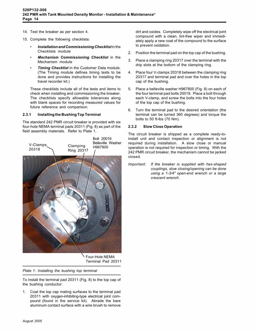
2.3.1 Installing the Bushing Top Terminal
The standard 242 PMR circuit breaker is provided with sixfour-hole NEMA terminal pads 20311 (Fig. 8) as part of thefield assembly materials. Refer to Plate 1.
Plate 1: Installing the bushing top terminal
To install the terminal pad 20311 (Fig. 8) to the top cap ofthe bushing conductor:
1. Coat the top cap mating surfaces to the terminal pad20311 with oxygen-inhibiting-type electrical joint com-pound (found in the service kit). Abrade the barealuminum contact surface with a wire brush to remove
dirt and oxides. Completely wipe off the electrical jointcompound with a clean, lint-free wiper and immedi-ately apply a new coat of the compound to the surfaceto prevent oxidation.
2. Position the terminal pad on the top cap of the bushing.
3. Place a clamping ring 20317 over the terminal with thedrip slots at the bottom of the clamping ring.
4. Place four V-clamps 20318 between the clamping ring20317 and terminal pad and over the holes in the topcap of the bushing.
5. Place a belleville washer H967800 (Fig. 8) on each ofthe four terminal pad bolts 20019. Place a bolt througheach V-clamp, and screw the bolts into the four holesof the top cap of the bushing.
6. Turn the terminal pad to the desired orientation (theterminal can be turned 360 degrees) and torque thebolts to 50 ft-lbs (70 Nm).
2.3.2 Slow Close Operation
The circuit breaker is shipped as a complete ready-to-install unit and contact inspection or alignment is notrequired during installation. A slow close or manualoperation is not required for inspection or timing. With the242 PMR circuit breaker, the mechanism cannot be jackedclosed.
Important: If the breaker is supplied with hex-shapedcouplings, slow closing/opening can be doneusing a 1-3/4" open-end wrench or a largecrescent wrench.
Four-Hole NEMATerminal Pad 20311
V-Clamps20318
ClampingRing 20317
Bolt 20019Belleville WasherH967800

526P132-006242 PMR with Tank Mounted Density Monitor - Installation & Maintenance©
Page 15
August 2005
3. SF6 Gas Reclaiming andFilling
During normal operation, the pole tank and entrance bush-ings are pressurized to 87 psig (0.60 MPa), when using atemperature compensated pressure gauge, with sulfurhexafluoride (SF6) gas. Maintaining a proper gas densityis critical to ensure the dielectric integrity of the pole units.
The SF6 gas density monitoring system compensates forpressure changes due to temperature variations and pro-vides alarm and lock-out functions if low gas densityproblems exist.
Depending on design, the breaker is equipped with eithera single gas density monitor or three.
The single density monitor design has a gas manifold(Figs. 6 and 11) that links the 3 pole units into a single gasdensity monitor system. The monitor is attached to the rightpole unit (Figs. 6 and 11).
If the breaker uses three monitors, a monitor is attached toeach pole unit. A quick disconnect valve 10154 (Fig. 11a/b)at each bellcrank assembly conveniently allows the indi-vidual pole units to be filled.
The SF6 gas can be reclaimed from one, two, or all threepole units as desired by removing the pressure gauge(s)and/or manifolds from the pole unit(s) and attaching inplace of each a hose from a gas service cart.
WarningUnder normal operating conditions, the quickdisconnect valve(s) 10154 at the pressuregauge(s) must be tightened to properly monitorthe SF6 gas density.
Important: For procedures that require the isolation of apole unit from the breaker's other pole units,follow the instructions in Section 3.5 on Isolat-ing a Pole Unit from the Gas System, payingcareful heed to ALL warnings and cautionarystatements.
Should the pole unit need to be opened, the SF6 gas needsto be reclaimed. The gas service unit (Plate 2) is theenvironmentally preferred and recommended equipmentto be used when reclaiming SF6 gas as per the procedurein section 3.1. This unit also can be used to evacuate airfrom pole units and to fill pole units with gas.
The gas service unit is an all-in-one, contained systemwhich allows the SF6 gas to be cost-efficiently and effec-tively reclaimed and recycled. The features on the gasservice unit provide the following distinct advantages:
� The unit is cost-efficient because it saves money byreclaiming and storing the expensive SF6 gas.
� The in-line filter on the unit removes moisture andarc by-product impurities from the recycled gas asit is being reclaimed.
� The unit is environmentally preferred because iteliminates the need to release the SF6 gas into theatmosphere.
� The built-in vacuum pump on the unit removes airand moisture from the breaker and eliminates theneed to have a separate vacuum pump.
� After the necessary vacuum is attained, the breakercan be refilled with gas directly from the gas serviceunit.
When using a gas service unit, make sure that an in-lineportable filter with a molecular sieve medium (desiccant)is installed on the gas service unit. The filter removesmoisture and decomposition products from the gas. Referto section 3.3 to install the filter. Place the filter vertically inthe line between the quick disconnect fill valve 10154 (Fig.5) and the SF6 gas service unit. Gas will be forced to flowthrough the desiccant in the filter/drier. Care must be takento ensure that liquid SF6 does not enter the portable filter orbreaker.
Important: The 13x molecular sieve (desiccant) must bereplaced after passing approximately 3500pounds of gas through the filter. Refer tosection 3.4.
Plate 2: Gas service unit
526P132-006242 PMR with Tank Mounted Density Monitor - Installation & Maintenance©
Page 16
August 2005
3.1 Reclaiming SF6 Gas from a Pole Unit
SF6 gas must be reclaimed before opening a pole unit. Gascan be reclaimed from one, two, or all three pole units.
DANGER
Remove the SF6 gas before attempt-ing to open the pole unit. Break thevacuum if the tank pressure is be-low atmospheric pressure.
Use a gas service unit (Plate 2) to reclaim SF6 gas from thepole unit. When using a gas service unit, make sure thatan in-line portable filter with a molecular sieve medium(desiccant) is installed. The filter removes moisture anddecomposition products from the gas. Refer to section 3.3to install the filter. Place the filter vertically in the linebetween the quick disconnect fill valve 10154 (Fig. 5) andthe SF6 gas service unit.
Important: The 13x molecular sieve (desiccant) must bereplaced after passing approximately 3500pounds of gas through the filter. Refer tosection 3.4.
It is not economical or environmentally wiseto exhaust the SF6 gas to the atmosphere.
The gas service unit should be used to reclaim SF6 gasonly. Therefore, no air or other gases should ever be in thetank of the gas service unit. Check that air is purged fromthe unit and that the SF6 gas already contained in the unitis of good quality (particularly in regards to gas moisturecontent). Use a moisture analyzer to check the moisturecontent of the gas in the gas service unit. The moisturecontent ideally should be less than 200 ppmV
Review instructions for the gas service unit if you are notalready familiar with the unit.
Gas in individual pole units can be reclaimed via the quickdisconnect gas valves at the bellcranks, after all the gasmanifolds and/or bellcrank-mounted density gauges havebeen removed. Follow the instructions in Section 3.5 if it isnecessary to isolate the pole unit from the gas system
Notice: If the breaker uses a single density monitor,gas can also be reclaimed from all three poleunits simultaneously, via the left pole's quickdisconnect valve.
To reclaim SF6 gas from one or more pole units:
1. Loosen the nut on the quick disconnect valve of thedensity gauge or gas manifold on each pole unit to bereclaimed. Remove the gauge(s) or manifold(s).
2. Attach the flexible hose from the gas service unit toeach pole unit to be reclaimed, screwing on the con-necting nuts up to the groove in the threads of thedisconnect (Malmquist) valve.
3. Evacuate the hose from the gas service unit to drive outair and moisture using the vacuum pump.
4. Screw the nuts fully onto each valve.
5. Follow the gas service unit procedures step-by-step toreclaim the SF6 gas until a vacuum of about 2 mm Hgis achieved. Then close all valves on the gas serviceunit. Break the vacuum by inserting a quick disconnectvalve adapter without a closure on the outside end intothe valve. Air will suck into the tank.
6. Since breaking the vacuum fills a pole unit with moistatmospheric air, it is strongly recommended to openthe pole unit and clean the internal components of thepole tank promptly after breaking vacuum. Refer tosection 5.2.1.
WarningIf powdery decomposition products are present(when the pole unit is opened) they must beremoved and disposed of as soon as possible asdescribed in section 6. Clean the breaker partspromptly after opening the pole unit to preventdamage caused by corrosive compoundsformed when decomposition products are ex-posed to moisture in the air.

526P132-006242 PMR with Tank Mounted Density Monitor - Installation & Maintenance©
Page 17
August 2005
3.2 Filling the Circuit Breaker with SF6 Gas
The properties of the sulfur hexafluoride (SF6) gas used inthe breaker must meet the specifications for sulfur hexafluo-ride according to ASTM D2472.
The circuit breaker should be filled with SF6 gas to apressure of 87 psig (0.60 MPa) when using a standardtemperature compensated pressure gauge. Refer to Fig-ures 3 and 4 when using a non-temperature compensatedpressure gauge.
Although the pole units can be filled using either a gascylinder (bottle) (section 3.2.1) or a gas service unit (section3.2.2), it is recommended to use the gas service unit. Thegas cylinder can be used to top off or fill the pole units aslong as the pole units have not been opened and containa definite positive pressure of SF6 gas.
Notice: If breakers were shipped with a partial chargeof dry nitrogen gas or if the pole units hadbeen opened, a new desiccant bag needs tobe installed in the open pole units (section5.2.3), the rear tank cover re-installed (sec-tion 5.2.4), and the pole units will need to beevacuated before being filled with SF6 gas asper section 3.2.2.2. Evacuation must be donewithin 30 minutes after desiccant replacement.
3.2.1 Filling a Pole Unit from a Gas Cylinder
Filling the breaker pole units with SF6 gas from a gascylinder should only be done if the pole tanks have not beenopened and a positive pressure of at least 5 psig (0.03MPa) at 68°F (20°C) remains in the pole tank. Using aportable in-line filter/drier is optional if filling from a gascylinder.
SF6 gas is available in standard industrial type cylinders.The adapter needed for connecting to the cylinder is a CGA#590 male left-hand thread connector. Cylinders contain-ing a charge of either 25 lbs or 115 lbs of gas are available.The pressure in the cylinder is 300 psi at 75°F (24°C).
Important: The gas cylinder should be vertical at alltimes to prevent introducing liquefied gas intothe circuit breaker. Particulate matter withinthe gas cylinder can be carried with the lique-fied gas into the breaker.
Typically when a domestic breaker is shipped from thefactory, it already is positively charged with SF6 gas toapproximately 5 psig (0.03 MPa). As long as this initialcharge of gas is present, the breaker can be simply toppedoff to the proper level on installation. However, before fillingthe breaker with SF6 gas, make sure that this positivepressure has not been lost due to leakage or damageduring shipping, etc.
If the positive charge of gas is gone, determine the causeand correct the problem. Refer to section 4.3 for leakchecking procedures.
When the leak has been corrected or if you are filling anoverseas breaker where the bushings had to be installed,refer to section 5.2.3 for instructions on replacing thedesiccant bag. Then, follow the procedure for evacuatingand refilling a pole unit which has been opened as persection 3.2.2.2. (Gas filling procedures vary in caseswhere the breaker pole units have been opened andunopened.)
Gas can be filled at an individual pole unit via the quickdisconnect valve at the bellcrank, after the gas manifold orbellcrank-mounted density gauge has been reinstalled.Follow the instructions in Section 3.5 if it is necessary toisolate the pole unit from the gas system
If the breaker uses a single density monitor, gas can alsobe filled at all three poles simultaneously via the left pole'squick disconnect valve 10154.
To fill the unopened pole unit(s) with gas from a gas cylinder:
1. Purge a hose and filter (if used) by allowing SF6 gas fromthe cylinder to pass through the hose driving out air andmoisture. (A quick blast purge through the hose is notsufficient to adequately eliminate air and moisture -especially if using a long hose with a large diameter.)
2. Decrease the gas flow and immediately begin con-necting a hose to each necessary pole unit valve. Referto Plate 3.

526P132-006242 PMR with Tank Mounted Density Monitor - Installation & Maintenance©
Page 18
August 2005
Notice: Perform tests as described in section 4 toensure that the breaker is operating properlybefore placing the breaker into service.
Initially the moisture content tends to be errone-ously high when the breaker is just filled with SF6gas. That is why ABB recommends, if possible,allowing three days to pass after filling thebreaker with gas before taking the moisturereading as per section 4.2. At that time, themoisture reading should more accurately re-flect the true moisture content of the gas.
One cylinder of gas will be sufficient to fill one breaker.Usable gas may remain in the cylinder after the breaker isfilled.
When filling during cold ambient temperatures, the cylin-der may be heated using any of the following methods toconvert the liquid SF6 in the cylinder to a gaseous state:
� An electric blanket heater;� Immersing the gas cylinder upright in a drum par-
tially filled with warm water so that approximately halfof the cylinder is immersed. Heat the water with aportable gas or electric heater.
WarningNever heat a gas cylinder with an open flame.Energize heaters only when transferring thegas. When heating the cylinder, be sure that thetemperature in the cylinder does not exceed100°F (38°C).
5. For single hose filling, unscrew the disconnect valvenut. Then remove the hoses. Pressurized gas in thehoses will escape to the atmosphere.
If an octopus hose is used, then unscrew eachdisconnect valve nut until the thread gap is visible.Then remove the hoses. Pressurized gas in thehoses will escape to the atmosphere.
6. After filling and removing the fill hose, reattach thepressure gauge or gas manifold on the pole unit andcheck that the nut on the quick disconnecting valve10154 (Fig. 11a/b) is tight.
Notice: Allow the gas pressure and temperature tostabilize for 15 minutes and re-check thepressure in the pole unit before removing thegas filling equipment.
Notice: Perform tests as described in section 4 toensure that the breaker is operating properlybefore placing the breaker into service.
Initially the moisture content tends to be errone-ously high when the breaker is just filled with SF6gas. That is why ABB recommends, if possible,allowing three days to pass after filling thebreaker with gas before taking the moisturereading as per section 4.2. At that time, themoisture reading should more accurately re-flect the true moisture content of the gas.
3. Attach a hose from the cylinder (with pressure gaugeand regulator somewhere in the hose line) to each poleto be filled. Connecting nuts at the valves should only bescrewed onto the valves up to the thread gaps until allhoses are connected. Then screw the nuts on fully.
Plate 3: Disconnect valve for connecting the fill hose
4. Fill the pole unit(s) to 87 psig (0.60 MPa) when usingthe standard temperature compensated pressuregauge. Refer to Figures 3 and 4 when using a non-temperature compensated pressure gauge.
Important: When using a non-temperature compensatedpressure gauge, compensate for tempera-ture variation as shown in the pressure vs.temperature characteristics of Figure 3. TheSF6 Gas Filling and Density Monitor Calibra-tion Chart in Figure 4 is a quick reference,tabular version of the characteristics in Figure3. For example, at 30°F (-1°C) the correct fillpressure would be 78.2 psig (0.54 MPa).
Notice: At higher altitudes the fill pressure at 68°F(20°C) is slightly different and increases incre-mentally almost linearly by approximately 1.4psig per 3000 ft for fill pressures at 68°F (20°C).
WarningThe gas regulator must be adjusted approxi-mately to the final fill pressure of the breaker (87psig (0.60 MPa)) at 68°F (20°C) such that the SF6plumbing, density monitor, and gauge are notover-pressurized. Compensate for tempera-ture variations as needed.
Do not over-pressurize the circuit breaker whenfilling the breaker with SF6 gas. Over-pressur-ization may cause the rupture disk to burst.
Notice: Allow the gas pressure and temperature tostabilize for 15 minutes and re-check thepressure in the pole unit before removing thegas filling equipment.

526P132-006242 PMR with Tank Mounted Density Monitor - Installation & Maintenance©
Page 19
August 2005
3.2.2 Filling Pole Units Using a Gas Service Unit
The gas service unit (Plate 2 in section 3) can be used tofill pole units which have never been opened, e.g. on initialinstallation of the breaker (section 3.2.2.1) or when evacu-ating and refilling pole units which have been opened(section 3.2.2.2).
When using a gas service unit, make sure that an in-lineportable filter with a molecular sieve medium (desiccant)is installed on the gas service unit. The filter removesmoisture and decomposition products from the gas. Referto section 3.3 to install the filter. Place the filter vertically inthe line between the quick disconnect fill valve 10154 (Fig.5) and the SF6 gas service unit. Gas will be forced to flowthrough the desiccant in the filter/drier. Care must be takento ensure that liquid SF6 does not enter the portable filter orbreaker.
Important: The 13x molecular sieve (desiccant) must bereplaced after passing approximately 3500pounds of gas through the filter. Refer tosection 3.4.
No air or gas other than SF6 should ever be in the tank ofthe gas service unit. Check that air is purged from the unitand that the SF6 gas already contained in the unit is of goodquality (particularly in regards to gas moisture content).Before refilling, use a moisture analyzer to check themoisture content of the gas in the gas service unit.
Review instructions for the gas service unit if you are notalready familiar with the unit.
3.2.2.1 Filling Unopened Pole Units - Initial Filling onInstallation (Typically for Domestic Breakers)
When the breaker is shipped from the factory, it already ispositively charged with SF6 gas to approximately 5 psig(0.03 MPa). As long as this initial charge of gas is present,the breaker can be simply topped off to the proper level oninstallation. However, before filling the breaker with SF6gas, make sure that this positive pressure has not beenlost due to leakage or damage during shipping, etc.
If the positive charge of gas is gone, determine the causeand correct the problem. Refer to section 4.3 for leakchecking procedures. When the leak has been corrected,refer to section 5.2.3 for instructions on replacing thedesiccant bag. Then, follow the procedures for closing,evacuating, and refilling a pole unit which has been openedas per sections 5.2.4 and 3.2.2.2.
Gas can be filled at an individual pole unit via the quickdisconnect valve at the bellcrank, after the gas manifold orbellcrank-mounted density gauge has been reinstalledFollow the instructions in Section 3.5 if it is necessary toisolate the pole unit from the gas system
If the breaker uses a single density monitor, gas can alsobe filled at all three poles simultaneously via the left pole'squick disconnect valve 10154.
To fill an unopened pole unit:
1. Remove the pressure gauge or manifold from the poleunit disconnect valve on the bellcrank housing.
2. Purge the hose from the gas service unit with a quantityof SF6 gas equal to approximately 10 times the volumeof the hose to eliminate air and moisture. (A quick blastpurge through the hose is not sufficient to adequatelyeliminate air and moisture - especially if using a longhose with a large diameter.)
3. Decrease the gas flow from the gas service unit andimmediately connect the hose to the disconnect valve,first up to each valve thread gap and then fully tightened.
4. Open the appropriate valve on the gas service unit.
Plate 4: Disconnect valve for connecting the fill hose

526P132-006242 PMR with Tank Mounted Density Monitor - Installation & Maintenance©
Page 20
August 2005
2. Attach the flexible hose from the gas service unit to thedisconnect valves on each pole to be evacuated.
Plate 5: Disconnect valve for connecting the fill hose
3. Start the vacuum pump and/or follow the gas service unitprocedures step-by-step to evacuate the pole unit(s).
4. Follow the gas service unit procedures step-by-stepto evacuate the pole tank(s). Pull a vacuum to below1.0 mm Hg absolute. (Use an accurate electronicvacuum gauge to verify the vacuum reading.) Oncevacuum has reached less than 1.0 mm Hg, hold thevacuum for a minimum of 1 hour.
5. After vacuum is complete, turn off the vacuum pump.
6. Fill the pole unit to 87 psig (0.60 MPa) when using thestandard temperature compensated pressure gauge.Refer to Figures 3 and 4 when using a non-tempera-ture compensated pressure gauge.
Important: Whenusing a non-temperature compensatedpressure gauge, compensate for tempera-ture variation as shown in the pressure vs.temperature characteristics of Figures 3 and4.
Notice: At higher altitudes the fill pressure at 68°F(20°C) is slightly different and increases incre-mentally almost linearly by approximately 1.4psig per 3000 ft for fill pressures at 68°F (20°C).
WarningDo not over-pressurize the circuit breaker whenfilling the breaker with SF6 gas. Over-pressur-ization may cause the rupture disk to fail.
Notice: Allow the gas pressure and temperature tostabilize for 15 minutes and re-check thepressure in the pole unit before removing thegas filling equipment.
5. Fill the pole unit to 87 psig (0.60 MPa) when using thestandard temperature compensated pressure gauge.Refer to Figures 3 and 4 when using a non-temperaturecompensated pressure gauge.
Important: When using a non-temperature compensatedpressure gauge, compensate for tempera-ture variation as shown in the pressure vs.temperature characteristics of Figure 3. TheSF6 Gas Filling and Density Monitor Calibra-tion Chart in Figure 4 is a quick reference,tabular version of the characteristics in Figure3. For example, at 30°F (-1°C) the correct fillpressure would be 78.2 psig (0.54 MPa).
Notice: At higher altitudes the fill pressure at 68°F(20°C) is slightly different and increases incre-mentally almost linearly by approximately 1.4psig per 3000 ft for fill pressures at 68°F (20°C).
WarningDo not over-pressurize the circuit breaker whenfilling the breaker with SF6 gas. Over-pressur-ization may cause the rupture disk to burst.
6. After filling and removing the fill hose, reattach thepressure gauge or gas manifold on the pole unit andcheck that the nut on the quick disconnecting valve10154 (Fig. 11a/b) is tight.
Notice: Allow the gas pressure and temperature tostabilize for 15 minutes and re-check thepressure in the pole unit before removing thegas filling equipment.
Notice: Perform tests as described in section 4 toensure that the breaker is operating properlybefore placing the breaker into service.
Initially the moisture content tends to be errone-ously high when the breaker is just filled with SF6gas. That is why ABB recommends, if possible,allowing three days to pass after filling thebreaker with gas before taking the moisturereading as per section 4.2. At that time, themoisture reading should more accurately re-flect the true moisture content of the gas.
3.2.2.2 Evacuating and Refilling Pole Units
Use this procedure for pole units which have been openedto evacuate pole units of air and refill with SF6 gas.
Notice: Since the pole units had been opened, a newdesiccant bag 10008 (Fig. 9) on the rear tankcover assembly must be installed just beforere-installing the rear tank cover assembly10032 and proceeding with the evacuation/refill procedure. (Refer to sections 5.2.3 and5.2.4 for specific instructions.)
To evacuate and refill one, two, or all three pole units:
1. Remove the pressure gauges or gas manifolds fromthe pole unit bellcrank housings.

526P132-006242 PMR with Tank Mounted Density Monitor - Installation & Maintenance©
Page 21
August 2005
7. When all pole units have been filled with SF6 gas,remove the filling hose and then reattach the densitygauge or gas manifold on each pole unit's disconnectvalve, and tighten the large nut.
WarningEnsure that the nut on each quick disconnectvalve 10154 is tight for proper operation.
8. Perform tests as described in section 4 to ensure thatthe breaker is operating properly before placing thebreaker into service.
Notice: Initially the moisture content tends to be errone-ously high when the breaker is just filled with SF6gas. That is why ABB recommends, if possible,allowing three days to pass after filling thebreaker with gas before taking the moisturereading as per section 4.2. At that time, themoisture reading should more accurately re-flect the true moisture content of the gas.
3.3 Installing the Portable In-Line Filter
A filter utilizing the 13x molecular sieve (desiccant) can beused on either the gas cylinder or on the gas service unit. Toinstall the portable in-line filter, place the filter vertically in theline between the pole unit quick disconnect valve and the SF6gas service unit or gas cylinder. The gas will be forced to flowthrough the desiccant. Use care to ensure that liquefied SF6does not enter the portable filter or breaker.
Replace the desiccant (13x molecular sieve) after passingapproximately 3500 pounds of gas through the filter. Referto section 3.4.
3.4 Replacing Desiccant in the Portable In-LineFilter
The portable in-line filter for the gas service unit incorpo-rates a 13x molecular sieve (desiccant) to remove moisturefrom the SF6 gas. When the desiccant is spent, it needs tobe replaced. (This desiccant is not to be confused with thedesiccant bag in the rear tank cover of the pole unit.)
The key rule of thumb when replacing the desiccant is toavoid exposing the desiccant to atmospheric moisture.Therefore, it is best to perform this replacement procedureindoors if possible. If hoses are not connected to the gasservice unit, always keep the flared cap in place to protectthe threads and sealed from the atmosphere.
(Perform this procedure indoors if possible.)
To replace the desiccant in the portable in-line filter:
1. Stand the gas service unit upright and remove the pipeplug at the bottom end of the unit, releasing the olddesiccant. Discard the used desiccant.
2. Check the plug and clean the threads thoroughly.
3. Apply Teflon tape and Rector Seal #2 to the pipe plugand replace the plug.
4. Pour the desiccant from the shipping container directlyinto the filter on the gas service unit using a funnel; fillto about 1 inch from the top of the unit. Fill the unit withdesiccant as quickly as possible to reduce the timewhich the molecular sieve and the interior of thecolumn are exposed to atmospheric moisture.
5. Install the top pipe plug as soon as the filter is filled.
3.5 Isolating the Pole Unit from the Gas System
If a breaker uses three gas density monitors, then eachpole unit is automatically isolated and there is no need tofurther follow the instructions in this section.
If a breaker uses only one monitor, a gas manifold (Figs.6 and 11) links the three pole units into a single gas densitymonitoring system. A Quick Disconnect Gas Valve 10154(Figs. 5 and 9) is at each bellcrank or tank belly which allowspole units to be isolated from the gas manifold as needed.This fitting has a groove in its barrel which serves as anindicator showing that the pole unit is either open to the gassystem or isolated. The groove is not visible when the poleunit is open to the gas manifold and the nut is tight.
DANGERBefore proceeding, isolate, ground,and de-energize the circuit breaker.
To isolate the pole unit from the gas system:
1. Turn or loosen the nut on the fitting until a large groove(Figs. 9-View A, 11) in the threads of the fitting is visible.When the groove is visible, stop turning the nut. Do notremove the nut completely. As long as the nut is justloosened and not removed, the tubing side of the fittingremains sealed in this intermediate position by O-rings and the pole unit is isolated. At this point, thefitting is self-sealed by a spring-loaded valve.
Notice: The tubing side to the fitting does not self-sealwhen the nut is removed completely and thetubing is pulled from the fitting. This is why thenut should not be completely removed.
If a pole unit needs to be opened, the SF6 gas must bereclaimed as per instructions in Section 3.2
WarningRemove the SF6 gas before attempting to openthe pole unit. Break the vacuum if the tankpressure is below atmospheric pressure.
After evacuating and/or refilling the pole unit, reconnect it tothe gas manifold by fully tightening the Quick DisconnectGas Valves 10154.
Important: Ensure that the nut on each Quick DisconnectGas Valve 10154 is tight for proper operation.

526P132-006242 PMR with Tank Mounted Density Monitor - Installation & Maintenance©
Page 22
August 2005
4.2.1 Measuring the Moisture
To ensure reliable moisture measurements, pay particularattention to cleanliness and prescribed procedure, par-ticularly as it applies to preventing moisture from contami-nating the moisture analyzer (hygrometer) and its connec-tions. It is important that the recommendations of theanalyzer supplier be followed carefully.
The gas can be sampled through a 1/4-inch NPT malefitting that is part of the sample valve tool T13480. To usethis tool, attach it to the malmquist adapter tool T13481(Figure 5). Both tools are available in the general mainte-nance tool kit assembly (available for order through ABB).
Use only dry stainless steel tubing to connect the moistureanalyzer to the disconnect gas valve on the bellcrank.
4.3 Leak Checking
After the breaker has been opened or if an SF6 leak issuspected, check the following threaded, O-ring and gas-ket connections with a hand-held halogen leak detector:
� Tube connections and fittings to the density gauge;� SF6 gas density monitors;� SF6 gas plumbing and gas manifolds;� Rupture disk;� Bushing flanges;� Rear tank cover assembly;� Bellcrank housing;� Interphase shaft seals with the breaker opened and
closed.
4.4 Operational and Timing Tests
Before placing the breaker into service, perform operationaland timing tests. Section 4.4.1 defines operational tests; theTiming module details procedures for timing tests.
4.4.1 Operational Tests
The control relays, protection devices, and schemes mustbe fully checked by operational tests to ensure that thebreaker is ready for service. Because the control schemesare usually designed as per customer specifications, op-erational tests vary depending upon the particular controlscheme. Refer to the breaker control schematic to deter-mine the necessary operational tests to be performed.Generally, operational tests include the following steps:
1. Assure that the circuit breaker will open and close electri-cally at both the local control switches and at the remotecontrol switches. If a local/remote or maintenance testswitch is used, verify that it is functioning properly.
2. Check the alarm and operation lock-out functions forproper actuation. One parameter is monitored: theoperating energy of the mechanism. To verify theoperating energy of the mechanism, refer to the "Com-missioning" section of the Mechanism module.
3. Verify that the anti-pumping circuitry is operating prop-erly as per your particular control scheme.
4. Test any optional devices i.e., undervoltage relays,reclose time delay relays, etc.
4. Testing
The following should be performed when installing thebreaker:
� Pole resistance measurement (section 4.1);� Moisture measurement of the SF6 gas (section 4.2);� Leak checking (section 4.3);� Operational and timing tests (section 4.4 and the
Customer Data module);� Checking the oil level in the mechanism (Mecha-
nism module).
4.1 Pole Resistance Measurement
Using a 100 A micro-ohmmeter (or millivolt drop meter),perform a contact resistance (or milliVolt drop) measure-ment on each pole of the breaker. Refer to the CustomerData module for the contact resistance value.
4.2 Moisture Measurement of the SF6 Gas
The maximum moisture level permitted in the SF6 gaswhen measured at 1 atmosphere of pressure is:
500 ppmV (by volume) at 68°F (20°C) forup to 3 days after filling
200 ppmV (by volume) at 68°F (20°C)after the pole unit has been allowed tostabilize for at least 3 or more days aftergas filling
Caution
Should the moisture content of the SF6 gasexceed 200 ppmV 3 or more days after gasfilling, the SF6 gas must be reclaimed and re-cycled through a drying filter. Before refilling,the circuit breaker must be evacuated to elimi-nate moisture using the procedure in section3.2.2.2 for evacuating and refilling a pole unitthat has been opened.
Because there is always a higher partial pressure ofmoisture vapor external to the pole unit, moisture will slowlymigrate into the pole units over time. This is why it'simportant to have a moisture content of no more than 200ppmV three days after filling the breaker with gas. Thedesiccant bags 10008 (Fig. 9) in each pole tank willsufficiently remove moisture from the gas. The desiccantbags are replaced whenever the interrupter is opened forinspection or replaced. However, the moisture content cango as high as 500 ppmV before requiring a dry-out proce-dure (using a drying filter) for the SF6 gas.
The maximum moisture content to be expected from an SF6gas cylinder is:
SF6 Dew Point of -50°F (-45°C) or 63 PPM by volume
Use a moisture analyzer (hygrometer) to measure themoisture content of the SF6 gas in each pole unit. Refer tosection 4.2.1.

526P132-006242 PMR with Tank Mounted Density Monitor - Installation & Maintenance©
Page 23
August 2005
4.5 Check the Oil Level in the Mechanism
Check the oil level in the mechanism every year. Refer to theMechanism module for instructions on checking the oillevel.
4.6 Density Monitor Set Point Tests
4.6.1 Tests Using Pole Unit Gas
Test Procedure:
1 Remove cover assembly (one nut at bottom of cover)and push down and out of the way.
2 Remove density monitor from existing disconnectvalve.
3 Attach test device at existing disconnect valve. Valves# 1 and # 2 must be closed.
4 Attach density monitor to disconnect valve on testdevice.
5 Use valve # 1 to pressurize the density monitor. Slowlybleed off pressure with valve # 2, monitoring the alarmcontacts of the density monitor. Replace monitor if setpoints are more than 2 psi out of the specified range.
6 When testing is complete, close all valves, remove thedensity monitor from the test device, remove the testdevice, reattach density monitor to the tank mounteddisconnect valve, apply Dow 1292 grease to the tankboss surface, and attach the cover assembly. Makesure that the wires are not trapped and the wireterminations at the monitor are in good condition.Tighten the cover retaining nut (use Loctite 242 onthreaded stud) until there is a sudden increase intorque . The cover will be flat against the tank boss atthis point. Inspect the cover gasket and make sure itis sealed against the tank boss.
7 Reattach the plastic caplug over the stud end, turningwhile pushing to engage the stud threads into thecaplug end shape.
Illustration 2Density Monitor Calibration Tool
(T993DMM)Using Pole Unit Gas
Tank
Existing QuickDisconnect Valve
Pressurizing Valve(Valve #1)
Pressure Gauge (Density)
Manifold Block
Density Monitor
Cover hangingfrom Conduit
Flexible Conduit
Disconnect Valve
Gas Release Valve(Valve #2)
Tank Boss

526P132-006242 PMR with Tank Mounted Density Monitor - Installation & Maintenance©
Page 24
August 2005
4.6.2 Tests Using a Separate Gas Source
Test Procedure:
1 Remove cover assembly (one nut at bottom of cover)and push down and out of the way.
2 Remove density monitor from existing disconnectvalve.
3 Attach density monitor to test device disconnect valve.
4 Attach hose from a gas bottle (N2 suggested) to valveon test device.
5 Use valve to pressurize the density monitor. Removehose and slowly bleed off pressure with valve, moni-toring the alarm contacts of the density monitor. Re-place monitor if set points are more than 2 psi out ofthe specified range.
6 When testing is complete, remove the density monitorfrom the test device, reattach density monitor to thetank mounted disconnect valve, apply Dow 1292 greaseto the tank boss surface, and attach the cover assem-bly. Make sure that the wires are not trapped and thewire terminations at the monitor are in good condition.Tighten the cover retaining nut (use Loctite 242 onthreaded stud) until there is a sudden increase intorque . The cover will be flat against the tank boss atthis point. Inspect the cover gasket and make sure itis sealed against the tank boss.
7 Reattach the plastic caplug over the stud end, turningwhile pushing to engage the stud threads into thecaplug end shape.
Illustration 3Density Monitor Calibration Tool
(T994DMM)Using Separate Gas Source
Existing Density Monitor
Disconnect Valve
Pressure Gauge
Fill/Release Valve
Test Gas Source
Provide Support HereManifold BlockCover, hanging
from Conduit
Flexible Conduit
Existing QuickDisconnect Valve
Tank
Tank Boss

526P132-006242 PMR with Tank Mounted Density Monitor - Installation & Maintenance©
Page 25
August 2005
5. Maintenance
Procedures, materials, and equipment required for routinemaintenance and testing of the 242 PMR circuit breakersare described in this portion of the module. By following themaintenance procedures in this manual, the 242 PMRcircuit breaker will provide years of reliable, dependableservice. Routine minimal maintenance checks are recom-mended yearly and every 5-years (see Table 1).
Important: 5-Year Maintenance Checklists are includedin the Checklists module. A Timing Checklistis in the Customer Data module. Thesechecklists include the necessary items tocheck when performing routine maintenanceon the breaker. The checklists specify allow-able tolerances along with blank spaces forrecording measured values for future refer-ence and comparison.
Interrupter maintenance is based on the current load on theinterrupter contacts. If the breaker is equipped with aCondition Monitoring Unit (CMU), the CMU indicates wheninterrupter maintenance (replacing nozzles and contacts inthe interrupter) is required. Refer to the Interrupters mod-ule for details and the checklist for interrupter mainte-nance.
In the absence of a CMU, interrupter maintenance isscheduled according to guidelines suggested in the Inter-rupters module.
Table 1 on the next page provides a list of maintenancecheckpoints and suggested inspection frequency for gen-eral breaker maintenance. Specific maintenance proce-dures for components such as the mechanism and inter-rupters are found in their respective modules.
A service kit and any special tools required for this breakershould have been included with the original breaker ship-ment. Refer to the Customer Data module for a list ofrequired and optional special tools and materials.
All personnel designated to inspect and maintain thisbreaker must review section 6 in this module.
DANGERTo prevent injury or equipment dam-age, the breaker must be removedfrom service, isolated, and groundedbefore performing any maintenance.
DO NOT WEAR POLYESTER, ACETATE, NYLON, OR RAYONCLOTHING (SUCH AS SHINY-TYPE SKI JACKETS ANDWIND BREAKERS WHICH USUALLY CONTAIN NYLON)AROUND LIVE ELECTRICAL EQUIPMENT.
DANGERFailure to observe the requirementsof OSHA Standard 1910.269 cancause death or severe burns anddisfigurement. That standard spe-cifically prohibits the wearing of poly-ester, acetate, nylon, or rayon cloth-ing by employees working with ex-posure to electric arcs or flames.
5.1 Maintenance Tips
� During maintenance, especially if the pole units areopen to the atmosphere, avoid introducing loosedirt, especially metallic particles, into an open poleunit. This material can cause dielectric failure.
� Protect insulating surfaces from physical, damage(nicks and scratches) and keep surfaces clean anddry at all times.
� In silverplated joints, place the Loctite in the boltholes and not on the bolt threads.
� Wear snug-fitting cloth gloves when handling insu-lating parts and surfaces.
� Wipe insulating surfaces with new, clean lint-freewipers dampened with denatured ethyl alcohol.
Important: Never clean an insulating component with thesame wiper used to clean aluminum or metalparts.
5.1.1 Applying Loctite
Apply Loctite Threadlocker to all critical bolted joints. Fourtypes of Loctite are used for specific applications: 222, 242,262, and 271. The Torque Tables 2a and 2b specify therecommended torque and type of Loctite to be applied to allfasteners (U.S. Standard and metric) in the breaker exceptwhere specified otherwise. Remove all old Loctite frombolt threads and in blind holes. Allow adequate time for allthreads to dry prior to re-assembling parts.
Caution
In silverplated joints, place the Loctite in the boltholes and not on the bolt threads. For all otherjoints, unless otherwise indicated, apply one totwo drops of Loctite sparingly to the threads atthe end of the bolt.
If used improperly, especially in current carrying joints,Loctite can squeeze between contact areas and may causea high resistance joint. Ensure that excess Loctite does notsqueeze into contact areas.

526P132-006242 PMR with Tank Mounted Density Monitor - Installation & Maintenance©
Page 26
August 2005
1elbaT
elbaTecnanetniaMdetsegguS
noitidnoC/metI
slavretnInoitcepsnI
ylraeYrekaerB()ecivres-ni
sraeY7-5morfevomeR(
)ecivres
snoitarepOforebmuNdroceR V V
ytisneD/erusserPsaG6FSkcehC V V
noitarepOreporProfsretaeHnoitasnednoC-itnAkcehC V V
skcarCrofsrotalusnIkcehC V V
noitarepOreporProfsretaeHknaTkcehC tiucricehttseT tiucricehttseT
sgnitteSrotinoMytisneDsaG6FSkcehC - T
saG6FSehtfotnetnoCerutsioMkcehC - T
snoitcennoCgnilaeSsaGdna,sgnittiF,segnalFllatseTkaeL - T
gnimiTrekaerBtiucriCmrofreP - T
stnemerusaeM)smhO-orciM(ecnatsiseRtcatnoCmrofreP - T
ssenthgiTroferawdraHgnihsuBkcehC - T
ssenthgiTroferawdraHknaTkcehC).cte,segnalfflahknat,sdaehknatgnidulcni( - T
ssenthgiTroferawdraHksiDerutpuRkcehC - T
)egakniLhctiwSyrailixuAgnidulcni(egakniLgnitarepOrekaerBkcehCsnoitcennocfossenthgitrof - T
tsilkcehCecnanetniaMetelpmoC - ehtotrefeReludomstsilkcehC
ecnanetniaMmsinahceM
msinahceMehtnileveLliOciluardyHkcehC V V
noitarepOreporProfsretaeHnoitasnednoC-itnAmsinahceMkcehC V V
ciluardyhevissecxefonoitacidnirof(retnuoCtratSrotoMpmuPkcehC)sliatedrofeludommsinahceMehtotrefer-stratspmup V V
sgnitteShctiwStimiLmsinahceMyfireV - T
raeWevissecxErofsehsurBrotoMgnigrahCehtkcehC - T
tnemtsujdAreporProfhctiwSyrailixuAkcehC - T
thgiTerAslanimreTgniriWdnaerawdraHgnitnuoMmsinahceMtahTkcehC - T
ecnanetniaMretpurretnI
noitidnoCahtiwdeppiuqesirekaerbruoyfIetacidnilliwtinusiht,)UMC(tinUgnirotinoM
retpurretniehtecalperotyrassecensitinehw,UMCafoecnesbaehtnI.stcatnocdnaselzzon
.1elbaT,eludomsretpurretnIehtotrefer
sretnuocdnaseguagdaerotstenibacgninepoeriuqeryam,noitcepsnIlausiV-V
serudecorpno-sdnahdnaecivresmorfrekaerbgnivomerseriuqer-noitcepsnIlacisyhP-T
dedeennoitcepsnionsetacidni"-"
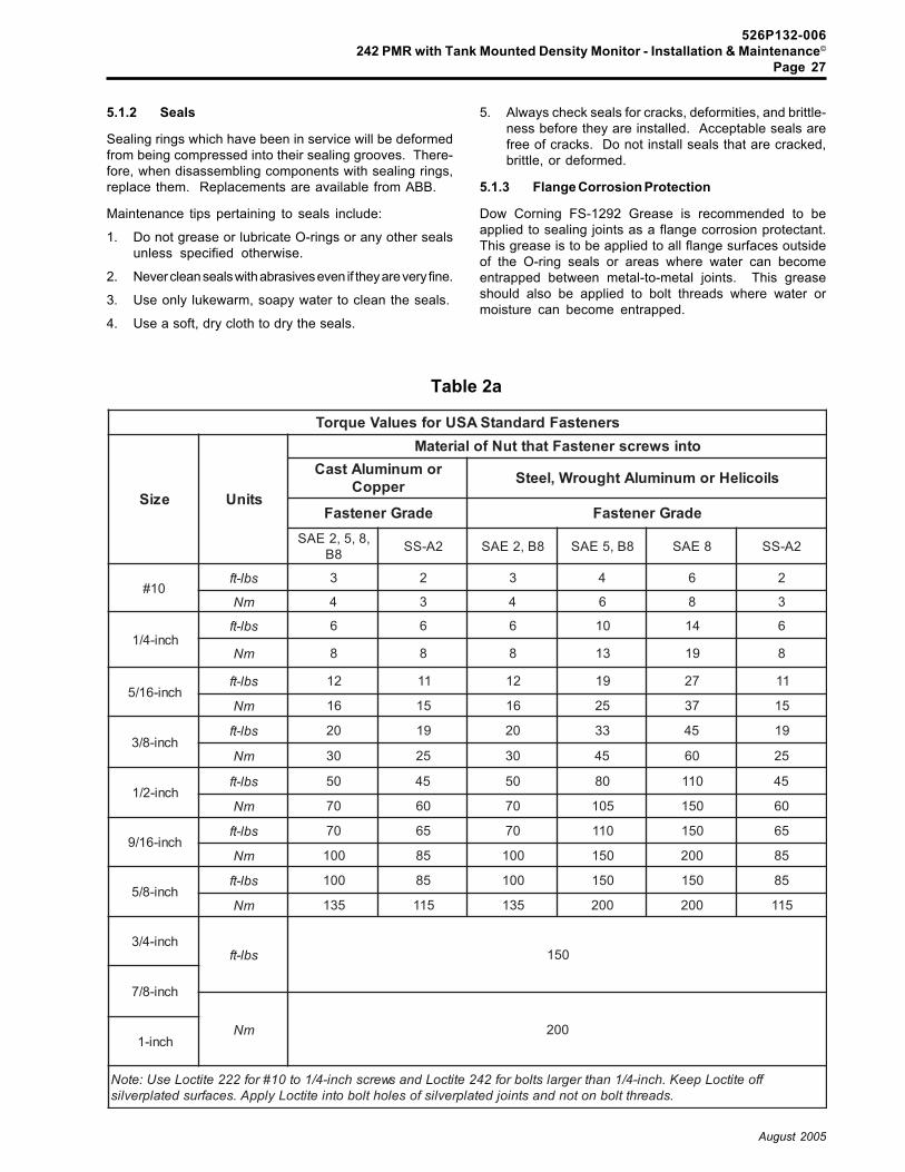
526P132-006242 PMR with Tank Mounted Density Monitor - Installation & Maintenance©
Page 27
August 2005
5.1.2 Seals
Sealing rings which have been in service will be deformedfrom being compressed into their sealing grooves. There-fore, when disassembling components with sealing rings,replace them. Replacements are available from ABB.
Maintenance tips pertaining to seals include:
1. Do not grease or lubricate O-rings or any other sealsunless specified otherwise.
2. Never clean seals with abrasives even if they are very fine.
3. Use only lukewarm, soapy water to clean the seals.
4. Use a soft, dry cloth to dry the seals.
5. Always check seals for cracks, deformities, and brittle-ness before they are installed. Acceptable seals arefree of cracks. Do not install seals that are cracked,brittle, or deformed.
5.1.3 Flange Corrosion Protection
Dow Corning FS-1292 Grease is recommended to beapplied to sealing joints as a flange corrosion protectant.This grease is to be applied to all flange surfaces outsideof the O-ring seals or areas where water can becomeentrapped between metal-to-metal joints. This greaseshould also be applied to bolt threads where water ormoisture can become entrapped.
Table 2a
srenetsaFdradnatSASUrofseulaVeuqroT
eziS stinU
otniswercsrenetsaFtahttuNfolairetaMromunimulAtsaC
reppoC sliocileHromunimulAthguorW,leetS
edarGrenetsaF edarGrenetsaF,8,5,2EAS
8B 2A-SS 8B,2EAS 8B,5EAS 8EAS 2A-SS
01#sbl-tf 3 2 3 4 6 2
mN 4 3 4 6 8 3
hcni-4/1sbl-tf 6 6 6 01 41 6
mN 8 8 8 31 91 8
hcni-61/5sbl-tf 21 11 21 91 72 11
mN 61 51 61 52 73 51
hcni-8/3sbl-tf 02 91 02 33 54 91
mN 03 52 03 54 06 52
hcni-2/1sbl-tf 05 54 05 08 011 54
mN 07 06 07 501 051 06
hcni-61/9sbl-tf 07 56 07 011 051 56
mN 001 58 001 051 002 58
hcni-8/5sbl-tf 001 58 001 051 051 58
mN 531 511 531 002 002 511
hcni-4/3sbl-tf 051
hcni-8/7
mN 002hcni-1
ffoetitcoLpeeK.hcni-4/1nahtregralstlobrof242etitcoLdnaswercshcni-4/1ot01#rof222etitcoLesU:etoN.sdaerhttlobnotondnastniojdetalprevlisfoselohtlobotnietitcoLylppA.secafrusdetalprevlis
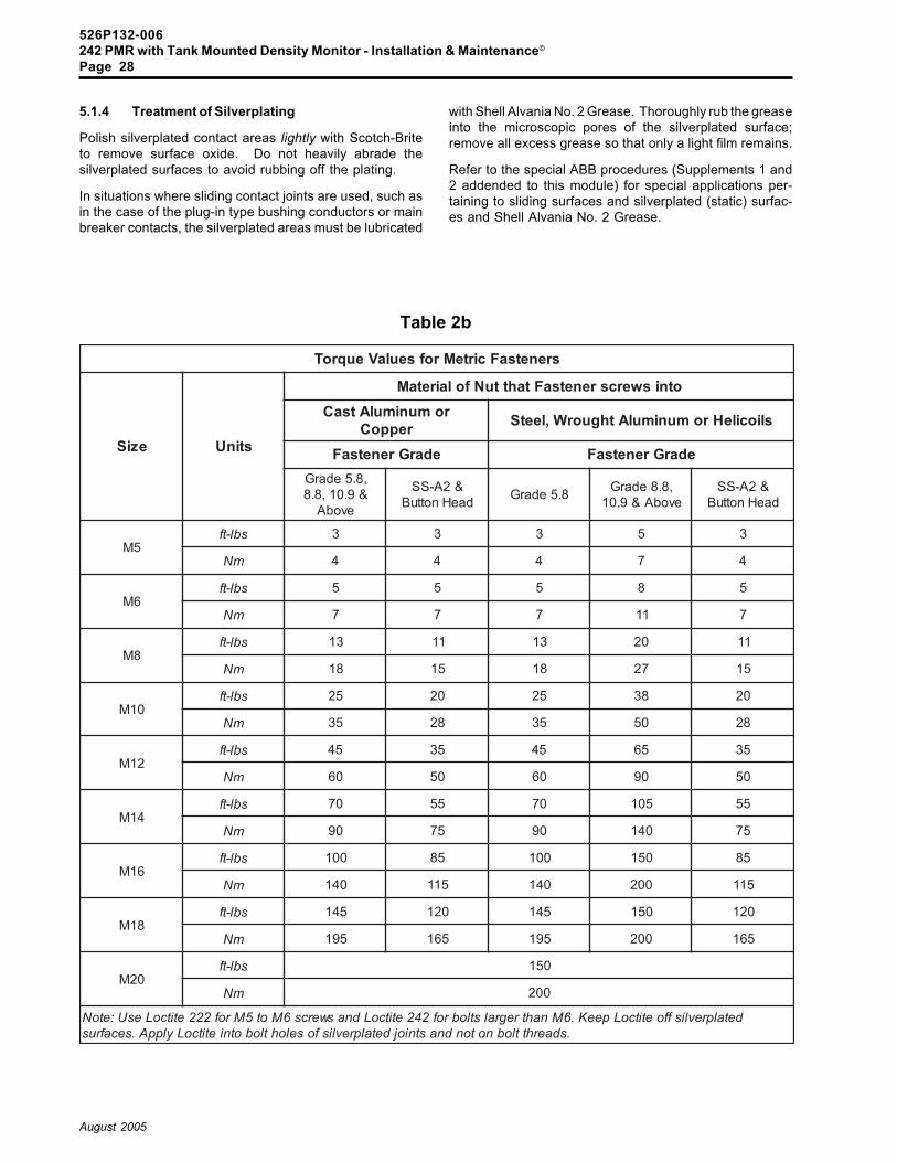
526P132-006242 PMR with Tank Mounted Density Monitor - Installation & Maintenance©
Page 28
August 2005
5.1.4 Treatment of Silverplating
Polish silverplated contact areas lightly with Scotch-Briteto remove surface oxide. Do not heavily abrade thesilverplated surfaces to avoid rubbing off the plating.
In situations where sliding contact joints are used, such asin the case of the plug-in type bushing conductors or mainbreaker contacts, the silverplated areas must be lubricated
with Shell Alvania No. 2 Grease. Thoroughly rub the greaseinto the microscopic pores of the silverplated surface;remove all excess grease so that only a light film remains.
Refer to the special ABB procedures (Supplements 1 and2 addended to this module) for special applications per-taining to sliding surfaces and silverplated (static) surfac-es and Shell Alvania No. 2 Grease.
Table 2b
srenetsaFcirteMrofseulaVeuqroT
eziS stinU
otniswercsrenetsaFtahttuNfolairetaMromunimulAtsaC
reppoC sliocileHromunimulAthguorW,leetS
edarGrenetsaF edarGrenetsaF,8.5edarG
&9.01,8.8evobA
&2A-SSdaeHnottuB 8.5edarG ,8.8edarG
evobA&9.01&2A-SS
daeHnottuB
5Msbl-tf 3 3 3 5 3
mN 4 4 4 7 4
6Msbl-tf 5 5 5 8 5
mN 7 7 7 11 7
8Msbl-tf 31 11 31 02 11
mN 81 51 81 72 51
01Msbl-tf 52 02 52 83 02
mN 53 82 53 05 82
21Msbl-tf 54 53 54 56 53
mN 06 05 06 09 05
41Msbl-tf 07 55 07 501 55
mN 09 57 09 041 57
61Msbl-tf 001 58 001 051 58
mN 041 511 041 002 511
81Msbl-tf 541 021 541 051 021
mN 591 561 591 002 561
02Msbl-tf 051
mN 002
detalprevlisffoetitcoLpeeK.6Mnahtregralstlobrof242etitcoLdnaswercs6Mot5Mrof222etitcoLesU:etoN.sdaerhttlobnotondnastniojdetalprevlisfoselohtlobotnietitcoLylppA.secafrus

526P132-006242 PMR with Tank Mounted Density Monitor - Installation & Maintenance©
Page 29
August 2005
5.2 Pole Unit Maintenance Procedures
Special pole unit maintenance procedures include:
� Removing the rear tank cover and cleaning the poletank (section 5.2.1);
� Replacing the rupture disk (section 5.2.2);� Replacing the desiccant bag (section 5.2.3);� Re-installing the rear tank cover assembly (section
5.2.4);� Isolating a pole unit (section 5.2.5);� Rebuilding the bellcrank (section 5.2.6);� Removing/installing current transformers (section
5.2.7);� SF6 gas density monitor calibration (section 5.2.8).
DANGERTo prevent injury or equipment dam-age, the breaker must be removedfrom service, isolated, and groundedbefore performing any maintenanceprocedures.
5.2.1 Removing the Rear Tank Cover and Cleaningthe Pole Tank
Prior to removing the rear tank cover assembly 10032 (Fig.9), reclaim the SF6 gas from the pole unit as described insection 3.1. Work on one pole unit at a time. Do not openall three pole units at once if the units have been in servicefor a while.
When opening a pole unit which has been in service for awhile, a significant amount of SF6 decomposition products(in the form of a powder) can accumulate in the pole unit andon the interrupter and within the bushing internal walls.(These decomposition products are formed by heat pro-duced during current interruption.) As long as the pole unitis sealed and the internal atmosphere is dry, these decom-position products pose no inherent threat to the breaker.However, when exposed to ambient air moisture, such aswhen the pole unit is opened, these SF6 decompositionproducts can quickly form corrosive and conductive com-pounds which are aggressive toward materials within thecircuit breaker, especially insulating surfaces, if subjectedto prolonged exposure to atmospheric air. Refer to section6 for more details.
WarningSolid SF6 decomposition products could be harm-ful if swallowed by humans or animals. Do notinhale or allow decomposition products to comein contact with the skin, eyes, and respiratorysystem. Severe irritation or burning may result.As a precaution, wear gloves, protective cloth-ing, and a respirator before removing the reartank cover assembly.
Observe all safety precautions pertaining to handling SF6gas and its by-products as per section 6.
Open the pole tank by removing the tank end bolts 10071(Fig. 9) and washers holding the rear tank cover assembly10032 in place.
WarningIf powdery decomposition products are presentaccompanied by an odor of rotten eggs (whenthe pole unit is opened) they must be removedand disposed of as soon as possible as de-scribed in section 6. Give the most priority toremoving and cleaning the interrupter (as perinstructions in the Interrupters module). You willneed to work fast to minimize exposing thedecomposition products to atmospheric airmoisture.Clean the powder off the interrupter first, thenclean the internal surface of the bushing insula-tors as per instructions in the Bushings module.Then remove any lingering decomposition prod-ucts from the pole tank internal surface. Workon one pole unit at a time.
If decomposition products are present on parts,do not allow these parts to sit overnight with thispowder on them. Clean the parts off promptlyotherwise the parts will corrode.
Collect all powdered decomposition products with anapproved vacuum cleaner.
Wipe all internal tank surfaces, the bushing conductor20001 (Fig. 9), and interrupter, especially insulating sur-faces, with lint-free wipers dampened with denatured ethylalcohol.
Important: As an extra precaution, do not leave even aclean pole tank open overnight. Re-install therear tank cover with a few bolts to keep outdebris and moisture.
To re-install the rear tank cover assembly with a newdesiccant bag, refer to sections 5.2.3 and 5.2.4.

526P132-006242 PMR with Tank Mounted Density Monitor - Installation & Maintenance©
Page 30
August 2005
5.2.2 Replacing the Rupture Disk
The bottom of each pole tank is equipped with a nickelreverse buckling rupture disk 10017 (Figs. 9 and 10). If thedisk ruptures (for example from over-pressurization due toover-filling or as the result of a defective disk, etc.) it needsto be replaced. The burst pressure of the ruputre disk isgiven on the first sheet of the wiring diagram shipped withthe breaker.
The following procedure assumes that the pole unit isempty of SF6 gas.
To replace the rupture disk:
1. Remove the four bolts 10072 (Fig. 10) which fasten therupture disk holding ring 10036, O-ring 90035, andrupture disk 10017 in place. Refer to Illustration 4.
2. Replace the old rupture disk and rupture disk O-ringwith a new rupture disk 10017 and new rupture disk O-ring 90035.
Caution
Store rupture disks 10017 in individual boxes asreceived from the supplier. Avoid touching orbumping the domed center. Never set the diskdown on the domed center side and never installa rupture disk that is dented or scratched.
3. Clean all metal parts of the rupture disk assembly withlint-free wipers dampened with denatured ethyl alco-hol.
4. Apply FS-1292 to the threads of the four bolts 10072.
5. Clean out the O-ring groove with lint-free wipers damp-ened with denatured ethyl alcohol. Install a newrupture disk O-ring 90035. Make sure that the rupturedisk is centered over the 60 mm hole (Illustration 4)before proceeding.
6. Grease the recessed surface outside the O-ring withDow Corning FS-1292 Grease.
7. Re-install the rupture disk holding ring 10036 byinstalling the bolts 10072 (with FS-1292 Grease on thebolts) and washers H420A64012 using the appropri-ate torquing pattern to ensure even tightening andsealing. Torque the bolts to 50 ft-lbs.
Replace the desiccant bag with a new desiccant bag asdescribed in section 5.2.3 and then re-install the rear tankcover assembly as described in section 5.2.4.
10017RuptureDisk
10036Rupture DiskHolding Ring
Cross Sectional View
FS-1292Grease
60 mm Hole 90035O-Ring
Bolts 10072WasherFS-1292 to boltthreadsTorque to 50 ft-lbs
Illustration 4Rupture Disk Cover Assembly
FS-1292

526P132-006242 PMR with Tank Mounted Density Monitor - Installation & Maintenance©
Page 31
August 2005
5.2.3 Replacing the Desiccant Bag
"Desiccant" refers to a molecular sieve which removesmoisture as well as SF6 decomposition products from thegas. A desiccant bag 10008 (Fig. 9) is installed in every poleunit at the rear tank cover assembly 10032.
Important: Any time that a pole unit has been opened orotherwise exposed to the atmosphere, re-place the desiccant bag . The desiccant bagshould be installed immediately before thepole unit is closed with the evacuation pro-cess following soon thereafter to prevent pro-longed exposure to moist atmospheric air.
Before replacing the desiccant bag, perform the followingmaintenance procedures:
� Reclaim all SF6 gas from the tank as per section 3.1.� Remove the rear tank cover assembly as described
in section 5.2.1.
To replace the desiccant bag:
1. Obtain a new desiccant bag 10008 (Fig. 9 and Illustra-tion 5). These bags are shipped in a hermeticallysealed reinforced aluminum foil bag to prevent con-tamination due to atmospheric moisture. The date ofmanufacture is marked on the outer bag.
Important: Do not use any desiccant bags marked witha date that is over two years old.
2. Carefully open the outer aluminum bag at one end. Ifusing a knife or scissors, be careful not to tear the innerbag when opening the outer bag. Immediately checkthat the dot on the moisture indicator tag included in thebag is blue. If it is not blue, the outer bag may have beendamaged. In this case, do not use the new desiccantbag; discard it and get a new one.
The protective outer bag is sealed under vacuum asindicated by the �tight-fit.� However, in very warm am-bient temperatures, the molecular sieve gives off air ithas absorbed which may cause the outer bag toexpand and look like a pillow. This does not necessar-ily indicate that the desiccant is ineffective; the desic-cant bag still is usable.
3. Install the desiccant bag by removing the screws10095 (Fig. 9 and Illustration 5), which fasten the cover10037 to the rear tank cover assembly 10032. Placethe new desiccant bag between the cover and rear tankcover. Re-install the screws 10095. Torque thehardware as specified in Tables 2a/b.
4. Discard used desiccant bags with other decomposi-tion products. Regenerating the desiccant for reuse,although possible, is not recommended. Use precau-tions described in section 6.4 when removing thedesiccant bags.
Re-install the rear tank cover assembly and apply vacuumas soon as possible to avoid over-exposing the desiccantto moist atmospheric air. Refer to section 5.2.4.
Illustration 5Desiccant Bag and Rear Tank
Cover Assembly
DesiccantBag10008
Screws 10095
Cover 10037

526P132-006242 PMR with Tank Mounted Density Monitor - Installation & Maintenance©
Page 32
August 2005
5.2.4 Re-installing the Rear Tank Cover Assembly
Prior to re-installing the rear tank cover assembly 10032(Fig. 9), be sure to install a fresh desiccant bag 10008 (ifit has not already been done as per section 5.2.3).
To install the rear tank cover assembly 10032 (Fig. 9):
1. Grease the rear tank cover flange from the outercircumference of the O-ring groove to the outside edgeof the flange with Dow Corning FS-1292 Grease.
2. Install a new O-ring 90002 (Fig. 9) by pressing it firmlyinto the groove. This O-ring does not require lubrica-tion. (Refer to section 5.1.2 for guidelines about O-ringseals).
3. Apply FS-1292 Grease to the threads of the tank endbolts 10071 and re-install the rear tank cover assem-bly 10032 using these bolts with washersH420A64012. Torque the bolts as specified in Tables2a/b.
4. Evacuate and refill the breaker with SF6 gas; refer tosection 3.2.2.2.
5.2.5 Isolating a Pole Unit
Certain maintenance tasks require isolating a pole unitwhich entails de-coupling the interphase linkages. Even-tually, the more critical tasks of synchronizing the inter-rupter contacts and re-coupling the interphase linkagesarise.
DANGER
Before beginning this procedure,isolate the breaker from high volt-age and properly ground the break-er.
5.2.5.1 De-Coupling the Interphase Linkages(Removing the Interphase Shafts)
WarningBefore proceeding, verify that the operatingmechanism is discharged in the OPEN positionand that all control power is disabled.
To remove the right side interphase shaft 10204 (Fig. 12):
1. Punch out the roll pins 10209 from the couplings10205.
2. Slide the couplings 10205 onto the interphase shaft10204 and lift off the shaft.
To remove the left side interphase shaft 10204 (Fig. 12):
1. Remove cover 10208 (Fig. 12) and linkage accesscover 10212.
2. Remove the retaining bolt 10188 (Fig. 13) and washerH973A06504 which holds the crank wrist pin 10210 inplace.
3. Slide out the crank wrist pin 10210 and move themechanism pullrod assembly 10207 out of the way.
4. Remove the crank bolt 10233 and nut H420A58008from the center of the crank 10206.
5. Slide the crank 10206 onto the interphase shaft 10204(Fig. 12).
6. Punch out the roll pin 10209 from the coupling 10205.Slide the coupling onto the interphase shaft and lift thecrank and shaft away.
Proceed to section 5.2.5.2.
526P132-006242 PMR with Tank Mounted Density Monitor - Installation & Maintenance©
Page 33
August 2005
5.2.5.2 Synchronizing the Interrupter Contacts
If the interrupter units have been de-coupled, they must beproperly synchronized with each other before re-installingthe interphase linkages. To do this, all three interrupterunits must be pulled into the fully OPEN position asdescribed in the steps below. Only after all three interrupt-ers are pulled into the fully open position can the inter-phase linkages be re-installed.
WarningIt is absolutely essential that the interruptercontacts be properly synchronized with eachother as well as with the operating mechanism.
To synchronize the interrupter contacts:
1. Slide the manual open/close tool T13451 (Fig. 14)onto the splines of the bellcrank shaft 10156 (left)(Fig. 15), 10157 (center), or 10156 (right).
2. Facing the control cabinet (bellcrank end of the inter-rupter), with the ratchet handle on the manual open/close tool T13451 (Fig. 14), rotate the bellcrank shaftto the fully OPEN position by rotating the ratchethandle toward the rear of the breaker until you feel theinterrupter bottom out.
Caution
You must feel the interrupter bottom out whenrotating the bellcrank shaft to ensure that theinterrupter is in the fully OPEN position.
3. Repeat steps 1 and 2 for each bellcrank shaft.
4. Check the guide piston setting as per section 5.2.5.3.
5. Re-couple the interphase linkages as per section5.2.5.4.
5.2.5.3 Setting the Guide Piston Length
For breakers equipped with an HMB hydraulic mecha-nism, a guide piston screws 54040 (Fig. 20) screws ontop of the mechanism pullrod. A very important length 114mm, between the center of the piston pin 54045 and themechanism top plate must be attained to ensure properoperation. This length is attained by removing cotter pinA and turning the screw-on guide piston up or down asneeded. Re-install the cotter pin after attaining the dimen-sion.
5.2.5.4 Re-Coupling the Interphase Linkages(Re-installing the Interphase Shafts)
WarningBefore proceeding, verify that the interruptercontacts have been synchronized as describedin section 5.2.5.2 and that the operating mech-anism is discharged in the OPEN position andthat all control power is disabled. Open thedisconnects in the control cabinet to all AC andDC power sources.
Notice: Apply FS-1292 Grease to splined linkages.
To re-install the right side interphase shaft 10204 (Fig. 12):
1. Slide the couplings 10205 onto the right side inter-phase shaft 10204 and re-install the shaft. Make surethat the flatter side of the shaft is closest to the centerpole unit, facing down and horizontal.
2. Tap the roll pins 10209 into the couplings 10205.
To re-install the left side interphase shaft 10204 (Fig. 12):
1. Slide the linkage access cover 10212 (Fig. 12) over theleft side interphase shaft 10204 before re-installingthe shaft.
2. Slide the crank 10206 (Fig. 13) and coupling 10205(Fig. 12) onto the left side interphase shaft.
3. Re-install the left side interphase shaft aligning theline-up dot on the crank 10206 (Fig. 13) with the line-up dot located on one of the splines of the centerbellcrank shaft 10157.
Caution
The line-up dot on the crank and the line-up doton the center bellcrank shaft must be aligned toensure proper synchronization of the interrupt-ers with respect to the mechanism.
4. Apply Loctite 242 to the crank bolt 10233 and re-installthis bolt with nut H420A58008 into the crank 10206.Torque the bolt as per Tables 2a/b in this module.
5. Tap the roll pin 10209 (Fig. 12) into the coupling 10205.
6. Make sure that the interrupters are in the fully openposition. Fully open the mechanism by pushing downon the pullrod assembly to bottom the mechanism intoits opened position. Move the mechanism pullrodassembly 10207 into position and slide the crank wristpin 10210 (Fig. 13) into place.
Notice: The mechanism must be fully open.
The crank wrist pin usually can be re-installedwithout requiring any adjustment of the pullrodlength. However, because this pin is finelymachined for precision fitting, it is sometimesdifficult to insert the pin. Therefore a veryslight adjustment of the turnbuckling pullrodmay be required to align the pin. To adjust the

526P132-006242 PMR with Tank Mounted Density Monitor - Installation & Maintenance©
Page 34
August 2005
5.2.6.1 Rebuilding the Left or Right BellcrankAssembly
To rebuild the left or right bellcrank assembly 10159 or10160 (Fig. 15):
1. Install the buffer 10166 (Fig. 15) in the bellcrankhousing 10172 (left) or 10173 (right); secure the bufferwith retaining ring 10179.
2. Install bearing 10164 in the bellcrank.
3. Apply a light coat of ProAA2 Grease to the shaft sealassembly 10153 where shown in Figure 16. Re-install the shaft 10156 (Fig. 15) on the bellcrank.
4. Ensure that connector arm bolt 30150 (Fig. 17) andwasher H973A03004 are installed in the back side ofthe internal crank prior to installing the internal crank10162 (Fig. 15) on the shaft 10156.
5. Install the internal crank 10162.
6. Align the point center punch marks of the bellcrankshaft 10156 with the internal crank 10162 (Illustration6). Make sure that the "hooked" curved end of theinternal crank is facing the top of the bellcrank.
7. Apply a light coat of FS-1292-Grease to the shaft sealassembly 10153 where shown in Figure 16. Thegrease eases assembly of the O-rings and preventstwisting. Wipe off excess grease.
8. Install the shaft seal assembly on the bellcrank usingbolts 10182 (Fig. 15) and M8 flat washers; apply Loctite242 and torque as per Tables 2a/b. Refer to Plate 6.
9. Align the hole in the internal crank 10162 with thebellcrank access hole as shown in Illustration 6.
Plate 6: Shaft seal assembly
pullrod, loosen the jam nuts 10230 (Fig. 13)and 10229 and then turn the pullrod slightly(on the order of a half turn) until the pin fits.Apply Loctite 242 to the jam nuts and torqueas per Tables 2a/b in this module. If the pinalignment is off significantly, (more than 1mm) the interrupters may not be fully openedor properly synchronized.
7. Apply Loctite 222 to the retaining bolt 10188 and re-install this bolt with washer H973A06504 to hold thecrank wrist pin 10210 in place. Torque as per Tables2a/b in this module.
8. Re-install the covers 10208 (Fig. 12) and 10212.
After re-installing the interphase linkages, inspect thefollowing:
� If the pole unit was opened, a new desiccant bag10008 (Fig. 9) will need to be installed in the rear tankcover, the pole tank closed and an evacuation/refillprocedure must be performed as described in therespective sections 5.2.3, 5.2.4, and 3.2.2.2.
5.2.6 Rebuilding the Bellcrank Assembly
Each pole unit has a bellcrank assembly, 10151 (centerpole), (Fig. 15) 10159 (left pole) and 10160 (right pole). Theleft and right bellcrank assemblies are rebuilt the sameway (as per section 5.2.6.1); the center bellcrank assemblyis rebuilt slightly differently (as per section 5.2.6.2).
Align the point center punchmarks when assemblingthe bellcrank.
Illustration 6Side View of Bellcrank
10162Internal Crank

526P132-006242 PMR with Tank Mounted Density Monitor - Installation & Maintenance©
Page 35
August 2005
10. Remove the old O-ring 90002 (Fig. 15) at the bellcrankflange and clean the O-ring groove and flange withwipers dampened with denatured ethyl alcohol.
11. Install a new tank end O-ring 90002 on the bellcrankend of the pole tank flange.
12. Apply FS-1292 Grease to the mating flange of thebellcrank and pole tank and to the quick disconnectvalve 10154 shown in Figure 11a/b and install thisfitting on the bellcrank.
5.2.6.2 Rebuilding the Center Bellcrank Assembly
Rebuilding the center bellcrank assembly 10151 (Fig. 15),requires procuring two new shaft seal assemblies 10153(Fig. 16). Proceed as follows:
1. Install the buffer 10166 (Fig. 15) in the bellcrankhousing 10152 (center); secure the buffer with retain-ing ring 10179.
2. Clean and degrease the metal parts on the shaft sealassembly 10153 (Fig. 15). Apply FS-1292 Grease.
3. Apply a light coat of ProAA2 Grease to the two shaft sealassemblies 10153 where shown in Figure 16.
4. Apply a light and even coat of ProAA2 Grease to thebellcrank shafts 10157 (Fig. 15), sealing to edge of thelip seals while rotating the shaft. Re-install the shaftson the center bellcrank.
5. Ensure that the connector arm bolt 30150 (Fig. 17) andwasher H973A03004 are installed in the back side ofthe internal crank 10162 (Fig. 15) prior to installing theinternal crank on the shaft 10157.
6. Install the internal crank 10162.
5. Align the point center punch marks of the bellcrankshaft 10157 with the internal crank 10162 (Illustration6 from the previous section). Make sure that the"hooked" curved end of the internal crank is facing thetop of the bellcrank.
7. Apply a light coat of FS-1292-Grease to both shaft sealassemblies 10153 (Fig. 16).
8. Install a shaft seal assembly on either side of thebellcrank 10151 (Fig. 15) using bolts 10182 and M8 flatwashers; apply Loctite 242 and torque as per Tables2a/b. Refer to Plate 6 from the previous section.
9. Align the hole in the internal crank 10162 with thebellcrank access hole as shown in Illustration 6.
10. Remove the old O-ring 90002 (Fig. 15) at the bellcrankflange and clean the O-ring groove and flange withwipers dampened with denatured ethyl alcohol.
11. Install a new tank end O-ring 90002 on the bellcrankend of the pole tank flange.
12. Apply FS-1292 Grease to the mating flange of thebellcrank and pole tank and to the quick disconnectvalve 10154 shown in Figure 11a/b and install thisfitting on the bellcrank.
5.2.7 Removing/Installing Current Transformers
Refer to the last sheet on the wiring diagram for currenttransformer (CT) wiring, CT ratios, accuracies, relativeposition to breaker contacts, and any special connectionsfor test switches or plugs that may have been installed onthe breaker for testing and monitoring of the CTs. Thecurrent transformer location nameplate is located insidethe door of the main control cabinet and lists the ABB partnumbers for the CTs, the CT curve number, the ratio, andthe accuracy class.
Notice: Each current transformer secondary must beconnected to a relaying or metering burden orbe short circuited at all times.
Prior to removing/installing a CT or a protective cover 70001(Fig. 18), reclaim almost all of the SF6 gas (as per section3.1) to lower the system pressure to approximately 5 psig(0.03 MPa).
Caution
Do not stand on the CT protective cover, other-wise you could crush the cover or damage theseal around the lip of the bottom support.
To remove the CTs:
1. Start by removing the CT protective cover 70001 (Fig.18) as follows: remove the bolts 70009, nutsH673A09102, and flat washers H420A64008 at thebottom of the CT protective cover.
2. Carefully lift the protective cover over the top of thebushing; avoid damaging the porcelain glaze or sheds.
Caution
Bumping a pressurized bushing could result incracking the insulator and causing it to rupture.
3. Disconnect the CT leads either at the CTs or at thecontrol cabinet.
4. Using a light crane, carefully note the number ofpressboard spacers (70005, 70006, and 70007) in-stalled and lift the CT over the top of the bushing; avoidbumping or damaging the bushing insulator. Save thepressboard spacers for re-use on installation.

526P132-006242 PMR with Tank Mounted Density Monitor - Installation & Maintenance©
Page 36
August 2005
To install a CT:
1. Using a light crane, carefully lower the CT over the topof the bushing; avoid damaging the bushing insulator.
2. While lowering the CT in place, install the appropriatenumber of pressboard spacers 70005, 70006, and70007 (Fig. 18).
Caution
Pressboard spacers must be installed to en-sure that the CTs are isolated from the CTprotective cover 70001 and bottom support70003.
3. Connect the secondary leads to the shorting terminalblocks. Refer to Plate 7.
Caution
When re-installing the CT protective cover 70001(Fig. 18), be careful not to damage the insulatingseal 70002. This seal serves both as a weatherseal and an insulating barrier. Without thisinsulating barrier, the CT protective cover wouldform a continuous conducting loop around theCTS, thereby shorting the CTs and jeopardizingCT accuracy.
4. Carefully place the CT protective cover over the top ofthe de-pressurized bushing; avoid bumping the bush-ing. The CT protective cover should seat itself evenlyon the insulating seal without excessive force.
5. Re-install the bolts 70009 (Fig. 18), nuts H673A09102,and two flat washers H420A64008 at the bottom of theCT protective cover to fasten the cover to the support.
WarningEvacuate and fill the breaker with SF6 gas if thegas had been reclaimed as recommended. Re-fer to the section 3.2.2.2.
Plate 7: Shorting terminal blocks
526P132-006242 PMR with Tank Mounted Density Monitor - Installation & Maintenance©
Page 37
August 2005
5.2.8 SF6 Gas Density Monitor and Calibration
Since SF6 gas serves as the insulating and arc quenchingmedium within the pole tanks, it is essential that the properSF6 gas density be maintained. The SF6 gas density ischecked indirectly by monitoring pressure as a function oftemperature, i.e., a given temperature X and pressure Ycorrespond to a certain density (assuming a constantvolume).
Based on the correlation between temperature and pres-sure, the SF6 gas density monitor 60441 (Fig. 7) operatesas a temperature-compensated pressure switch to indi-rectly monitor the density of the SF6 gas.
The SF6 gas density monitor is calibrated at the factory asfollows:
� The temperature probe is set at 68°F (20°C);
� Switch C (Fig. 7) is set to close at 76 psig (0.52 MPa)at 68°F (20°C) (low gas density alarm point) withdecreasing pressure;
� Switches B1 and B2 (Fig. 7) provide alarm indicationand are set to close at 72 psig (0.50 MPa) � CLOSEBLOCK and TRIP BLOCK (or AUTO TRIP) if the SF6gas density is at or below 72 psig (0.50 MPa) at 68°F(20°C) (which is the minimum pressure necessaryto maintain the full interrupting rating). These con-tacts (63B1 & 63B2) generally close on loss of gasdensity and energize the appropriate relay(s) toexecute lock-out functions (or AUTO TRIP) with de-creasing pressure (unless alternate values arelisted in the wiring diagrams).
Note that at higher altitudes the alarm andlock-out pressures at 68°F (20°C) are slightlydifferent and increase incrementally almostlinearly by approximately 1.4 psig per 3000 ftfor alarm and lock-out pressures at 68°F(20°C).
WarningNever change the factory-set alarm and lock-out switch settings shown in the wiring dia-grams - otherwise breaker failure could result.
Breakers either have 1.) a single SF6 gas density monitormounted onto the left pole tank, a gas density gaugemounted onto the right pole tank's bellcrank housing, anda gas manifold connecting all three pole tanks; or 2.) threeSF6 gas density monitors, each mounted to a pole tank,with a gas density gauge mounted onto each pole tank'sbellcrank housing. In either design, each monitor haspressure switches. The pressure gauges are visible whenfacing the breaker cabinet front.
The density monitor can compensate for outdoor tempera-ture variations ranging from -55°F to 150°F (-40°C to 66°C).The monitor automatically adjusts the operating points ofthe pressure switch to higher or lower pressures based ontemperature changes. If the SF6 gas pressure drops below76 psig (0.52 MPa) at 68°F (20°C), the monitor actuates analarm. If the SF6 gas pressure drops below 72 psig (0.50MPa) at 68°F (20°C), the monitor will lock out circuit breakeroperation (or AUTO TRIP and BLOCK CLOSE) and providethe appropriate alarm.
Once the density monitor is isolated, low density alarmsimulations can be performed using test manifolds avail-able from ABB.
DANGER
To prevent personal injury and dam-age to the equipment, before begin-ning any calibration or adjustment,de-energize the breaker and removeit from service.
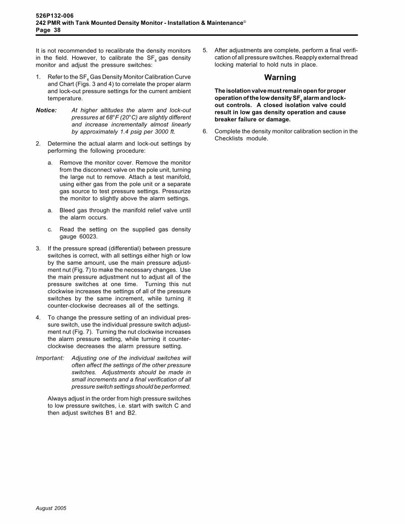
526P132-006242 PMR with Tank Mounted Density Monitor - Installation & Maintenance©
Page 38
August 2005
It is not recommended to recalibrate the density monitorsin the field. However, to calibrate the SF6 gas densitymonitor and adjust the pressure switches:
1. Refer to the SF6 Gas Density Monitor Calibration Curveand Chart (Figs. 3 and 4) to correlate the proper alarmand lock-out pressure settings for the current ambienttemperature.
Notice: At higher altitudes the alarm and lock-outpressures at 68°F (20°C) are slightly differentand increase incrementally almost linearlyby approximately 1.4 psig per 3000 ft.
2. Determine the actual alarm and lock-out settings byperforming the following procedure:
a. Remove the monitor cover. Remove the monitorfrom the disconnect valve on the pole unit, turningthe large nut to remove. Attach a test manifold,using either gas from the pole unit or a separategas source to test pressure settings. Pressurizethe monitor to slightly above the alarm settings.
a. Bleed gas through the manifold relief valve untilthe alarm occurs.
c. Read the setting on the supplied gas densitygauge 60023.
3. If the pressure spread (differential) between pressureswitches is correct, with all settings either high or lowby the same amount, use the main pressure adjust-ment nut (Fig. 7) to make the necessary changes. Usethe main pressure adjustment nut to adjust all of thepressure switches at one time. Turning this nutclockwise increases the settings of all of the pressureswitches by the same increment, while turning itcounter-clockwise decreases all of the settings.
4. To change the pressure setting of an individual pres-sure switch, use the individual pressure switch adjust-ment nut (Fig. 7). Turning the nut clockwise increasesthe alarm pressure setting, while turning it counter-clockwise decreases the alarm pressure setting.
Important: Adjusting one of the individual switches willoften affect the settings of the other pressureswitches. Adjustments should be made insmall increments and a final verification of allpressure switch settings should be performed.
Always adjust in the order from high pressure switchesto low pressure switches, i.e. start with switch C andthen adjust switches B1 and B2.
5. After adjustments are complete, perform a final verifi-cation of all pressure switches. Reapply external threadlocking material to hold nuts in place.
WarningThe isolation valve must remain open for properoperation of the low density SF6 alarm and lock-out controls. A closed isolation valve couldresult in low gas density operation and causebreaker failure or damage.
6. Complete the density monitor calibration section in theChecklists module.

526P132-006242 PMR with Tank Mounted Density Monitor - Installation & Maintenance©
Page 39
August 2005
6. Safe Handling of SF6
In its pure, natural state, sulfur hexafluoride (SF6) gas iscolorless, odorless, tasteless, possesses a low order oftoxicity, and is approximately five times heavier than air. SF6gas is chemically inert and non-flammable. The gas hasa high dielectric strength and thermal properties conducivefor insulating high voltage and quenching electrical arcs.
When SF6 gas is subjected to an electric arc within theinterrupter, heat causes the gas to decompose into poten-tially toxic by-products both in gaseous and white/tan/graypowder form. The amount of decomposition by-productsis a function of the intensity and duration of the arc.
When SF6 decomposition products are exposed to mois-ture, they tend to form corrosive and conductive com-pounds which can be both harmful to human beings andaggressive towards materials within the circuit breaker,especially insulating surfaces � if subjected to prolongedexposure. (In the presence of moist air, noxious decom-position products have a characteristic odor of rotten eggs.)
SF6 gas and its decomposition products present no injuryor illness problems if dealt with properly. As with otherchemicals, health hazards may exist under particular con-ditions, if exposure or handling is careless or improper.The only danger in breathing too much pure SF6 gas in anon-ventilated area is that it displaces oxygen and cancause suffocation if the oxygen content of the air is reducedfrom the normal 20 percent to less than 13 percent.
DANGER
Avoid inhaling large amounts of SF6gas and decomposition by-prod-ucts. Avoid skin or eye contact withthe decomposition products be-cause they can cause skin rashes,eye irritation, and chemical burns.Wear the prescribed protective gearindicated in section 6.1.
6.1 Equipment Used to Handle SF6 DecompositionProducts
Use the following equipment to perform maintenance onthe breaker if decomposition products may be present:
� Hooded disposable coveralls - Tyvec, Durafab, orequivalent - made of paper with nylon reinforcementmaterial;
� Non-Disposable Neoprene Gloves - 14-inch size;
� Non-Disposable Rubber Boots - 17-inch size, over-the-shoe style;
� Clean, oil-free dry air supply with a capability toprovide sufficient purging and ventilating capacity;
� Full-face Comfo II respirator or equivalent with twincartridges for organic vapors and acid gases, i.e.,GMC or equivalent;
� Supplied air-line respirator - MSA pressure demandtype with Ultravue face piece and web belt-mounteddemand regulator, 50 ft. of air supply hose, manifoldwith quick-disconnect and automatic shut-off out-lets, cylinder pressure regulator; must have NIOSH/MESA Approval No. TC-19C-93, or equivalent fromother manufacturer;
� Respirable, compressed air supply - 300 lb, ap-proved portable tank with air meeting Grade D, ANSIStandard Z86.1-1974 with supply hose inlet pres-sure between 80 to 100 psig;
� Industrial wet or dry type vacuum cleaner with non-metallic attachments, micro staphicidal filter ele-ments (particles to 0.3 microns), two 15-inch lengthsof plastic hose and coupler;
� Cleaning solvent: denatured ethyl alcohol.
6.1.1 Protective Gear
Minimum required protective gear to be worn when han-dling SF6 gas-insulated apparatus are:
� Gloves;� Full-face Comfo II respirator or equivalent with twin
cartridges for organic vapors and acid gases, i.e.,GMC or equivalent.
Full protective gear includes:
� Gloves;� Hooded disposable coveralls;� Non-Disposable Neoprene Gloves - 14-inch size;� Non-Disposable Rubber Boots - 17-inch size, over-
the-shoe style;� Supplied air-line respirator.
6.2 SF6 Gas Handling Safety and PurgingPractices
Safety practices when handling SF6 gas-insulated appara-tus are:
� Perform SF6 gas handling, filling or reclaiming out-doors;
� If procedures involving SF6 gas insulated equipmentmust be done indoors, work in a well-ventilated room;make sure the ventilating equipment is operating;
� No smoking;� No exposed heaters, flames, or arc-producing equip-
ment should be used in the area while the gas isbeing handled;
� If, when handling used SF6 gas, the odor of rotteneggs is detected, personnel not wearing respiratoryequipment should promptly evacuate the area;
� Correct any gas leaks at hose or fitting connectionsat the breaker, on the service cart, or at the cylinder.
� If a tent-like enclosure is used around the work area,use a dry air ventilation system while performingmaintenance work.

526P132-006242 PMR with Tank Mounted Density Monitor - Installation & Maintenance©
Page 40
August 2005
If decomposition products are found, remove them as persection 6.3. If no decomposition products are found:
1. Purge the apparatus thoroughly with dry air from asuitable source.
Important: Do not purge with damp or wet air as it canendanger the integrity of insulation materialsand prolong dry-out and reconditioning time.
It is only safe to assume that there may behazardous gaseous products present. Allpersonnel should stand clear of the appara-tus during purging.
2. Allow purging to continue long enough to assure aminimum of at least 10 complete air changes throughthe total apparatus before working on the equipment.If the SF6 gas has not been fully evacuated from theapparatus prior to purging, perform a minimum of 100air changes.
3. Reduce the purging air supply to a low level (approxi-mately 10 air changes per hour) to provide continuousventilation of the apparatus while personnel are work-ing internally in the apparatus.
6.3 Removing SF6 Decomposition Products
If significant arc powders or noxious odors are detectedupon opening a pole unit or any other apparatus:
1. Wear full protective clothing and a supplied air full-facerespirator.
2. Establish a restricted safety zone around the equip-ment. Personnel cannot enter this zone without wear-ing full protective gear. If performing this work out-doors, the zone may need to be extended downwind ofthe work site.
3. Use a vacuum cleaner equipped with filters. Thisvacuum cleaner should be used exclusively for remov-ing SF6 decomposition products.
4. Wipe up any remaining powdered decompositionproducts with rags using denatured ethyl alcohol.
5. Remove and dispose the molecular sieve (desiccant)within the apparatus as per section 6.4; keep the fullprotective gear on.
6. Place materials used and retrieved in clean-up opera-tions in large plastic or metal containers. Thesecontainers serve as refuse containers.
7. Proceed with purging as per section 6.2 after removingall decomposition products.
6.4 Disposing of Decomposition Products
Dispose the decomposition products outdoors since cor-rosive or toxic gases may evolve from the solid arc productsor from the molecular sieve (desiccant). Disposal of theSF6 residue involves neutralizing the decomposition prod-ucts.
Notice: Wear full protective gear during disposal.
To properly dispose of decomposition product residue:
1. Place materials used and retrieved in clean-up opera-tions in large plastic or metal containers. Thesecontainers serve as refuse containers.
2. Empty the vacuum cleaner housing and the absorp-tion filter material into the container.
3. Note or measure the volume of material in the con-tainer.
4. In a separate container (plastic pail), measure avolume of water 1.5 times that of the above refusematerial. Empty the water into the refuse containerpouring the water quickly at first then slowly. The watermixing with the SF6 refuse will produce some heat andfoam.
5. Measure a quantity of soda ash (sodium carbonate) orlime (calcium oxide) equal to at least one-quarter thevolume of the refuse and add this neutralizing agent tothe water-refuse material.
6. Add the cleaning rags, protective clothing (even thoughit is disposable), along with the filters from the vacuumcleaner and respirator to the neutralizing mixture in therefuse container.
7. Allow the refuse container to stand uncovered for 24hours.
8. Afterwards test the pH of the refuse mixture.
The mixture should be at least slightly alkaline (greaterthan 7). If the pH is between 7 and 10, the refuse is nowrendered harmless and may be disposed of in anormal manner as per local ordinances.
If the solution pH is less than 7, it is still acidic andharmful; add additional soda ash or lime to neutralizethe refuse mixture to a pH greater than 7 but less than10. Then dispose of the material as per local ordi-nances.

526P132-006242 PMR with Tank Mounted Density Monitor - Installation & Maintenance©
Page 41
August 2005
6.4.1 Removing SF6 Gas Residue from Tools andEquipment
To clean tools and equipment which have been exposedto SF6 decomposition products:
1. Prepare a mild (10%) lime or soda ash solution anduse this as the neutralizing solution.
2. Wash any hand tools, non-disposable protective gear,and equipment employed in the clean-up operation.
3. Vacuum some of this neutralizing solution through thehose and into the vacuum cleaner to neutralize par-ticles adhering to this equipment.
4. Rinse all washed tools and equipment thoroughly withwater.
5. Wash the rubber boots and Neoprene gloves in water.

526P132-006242 PMR with Tank Mounted Density Monitor - Installation & Maintenance©
Page 42
August 2005
10044
10043
Center of Gravity
60010
T13442
NEMAGroundingPad
10092Loctite 242
10017
Figure 1Lifting the Breaker
10017 Rupture Disk10043 Leg Extension10044 Support Structure10092 Lifting Lug60010 View Port WindowsT13442 Sling

526P132-006242 PMR with Tank Mounted Density Monitor - Installation & Maintenance©
Page 43
August 2005
6000
1An
ti-C
onde
nsat
ion
Hea
ter
6000
9R
emov
able
Pla
te60
010
View
Por
t Win
dow
6001
1C
ontro
l Cab
inet
Gro
und
Term
inal
6000
1
6001
1
6000
9
Figu
re 2
Con
trol
Cab
inet
600
00
6001
0
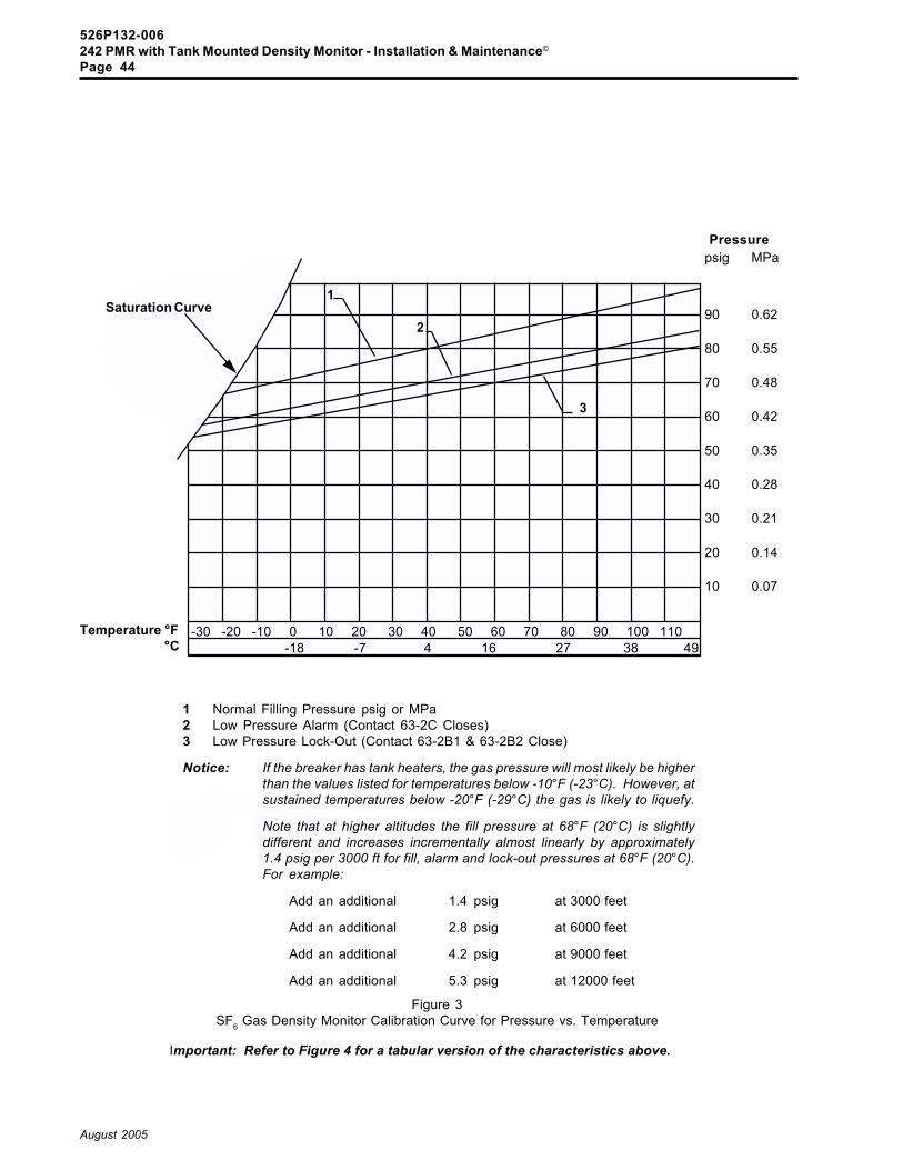
526P132-006242 PMR with Tank Mounted Density Monitor - Installation & Maintenance©
Page 44
August 2005
Important: Refer to Figure 4 for a tabular version of the characteristics above.
Figure 3SF6 Gas Density Monitor Calibration Curve for Pressure vs. Temperature
1 Normal Filling Pressure psig or MPa2 Low Pressure Alarm (Contact 63-2C Closes)3 Low Pressure Lock-Out (Contact 63-2B1 & 63-2B2 Close)
Notice: If the breaker has tank heaters, the gas pressure will most likely be higherthan the values listed for temperatures below -10°F (-23°C). However, atsustained temperatures below -20°F (-29°C) the gas is likely to liquefy.
Note that at higher altitudes the fill pressure at 68°F (20°C) is slightlydifferent and increases incrementally almost linearly by approximately1.4 psig per 3000 ft for fill, alarm and lock-out pressures at 68°F (20°C).For example:
Add an additional 1.4 psig at 3000 feet
Add an additional 2.8 psig at 6000 feet
Add an additional 4.2 psig at 9000 feet
Add an additional 5.3 psig at 12000 feet
psig MPa
90 0.62
80 0.55
70 0.48
60 0.42
50 0.35
40 0.28
30 0.21
20 0.14
10 0.07
1
2
3
Pressure
Temperature °F °C
Saturation Curve
-30 -20 -10 0 10 20 30 40 50 60 70 80 90 100 110 -18 -7 4 16 27 38 49

526P132-006242 PMR with Tank Mounted Density Monitor - Installation & Maintenance©
Page 45
August 2005
Tabular Version of the Pressure vs. Temperature Characteristics shown in Figure 3
Figure 4SF6 Gas Filling and Density Monitor Calibration Chart
Notice: If the breaker has tank heaters, the gas pressure will most likely be higher than the values listedfor ambient temperatures below -10°F (-23°C). However, at sustained temperatures below -20°F (-29°C) the gas is likely to partially liquefy.
Note that at higher altitudes the fill pressure at 68°F (20°C) is slightly different and increasesincrementally almost linearly by approximately 1.4 psig per 3000 ft for fill, alarm and lock-outpressures at 68°F (20°C). For example:
Add an additional 1.4 psig at 3000 feet
Add an additional 2.8 psig at 6000 feet
Add an additional 4.2 psig at 9000 feet
Add an additional 5.3 psig at 12000 feet
F.pmeT C.pmeT gisplliF* aPMlliF** mralA*gisp
mralA**aPM
tuO-kcoL*gisp
tuO-kcoL**aPM
04- 04- detarutaS detarutaS detarutaS detarutaS detarutaS detarutaS
03- 43- detarutaS detarutaS detarutaS detarutaS detarutaS detarutaS
02- 92- detarutaS detarutaS 0.85 04.0 9.45 83.0
01- 32- 8.86 74.0 0.06 14.0 9.65 93.0
0 81- 1.17 94.0 1.26 34.0 8.85 14.0
01 21- 4.37 15.0 0.46 44.0 8.06 24.0
02 7- 8.57 25.0 2.66 64.0 7.26 34.0
03 1- 2.87 45.0 1.86 74.0 7.46 54.0
04 4 5.08 65.0 2.07 84.0 6.66 64.0
05 01 8.28 75.0 3.27 05.0 5.86 74.0
06 61 2.58 95.0 3.47 15.0 4.07 94.0
86 02 0.78 06.0 0.67 25.0 0.27 05.0
07 12 6.78 06.0 4.67 35.0 3.27 05.0
08 72 0.09 26.0 5.87 45.0 2.47 15.0
09 23 3.29 46.0 5.08 65.0 2.67 35.0
001 83 7.49 56.0 7.28 75.0 2.87 45.0
011 34 1.79 76.0 8.48 85.0 1.08 55.0
)eguagerusserpdetasnepmocerutarepmetdradnatsehtgnisunehwgisp78otlliF(gisp2-/+*
aPM10.0-/+**
IMPORTANT: The shaded row indicates pressure readings ± 2 psi for circuit breakers equippedwith temperature compensated pressure gauges used on the pole units.

526P132-006242 PMR with Tank Mounted Density Monitor - Installation & Maintenance©
Page 46
August 2005
Figure 5Gas Charging Arrangement
T13446
10154
T13481
T13480
View ABreaker during NormalOperating Conditions
(or during shipping)
View BBreaker during
Filling Procedure
View CArrangement for
Gas Sampling
NPTMaleFitting
60023Note: Remove during
Gas Charging (View B)or Gas Sampling (View C)
10154 Quick Disconnect Gas Valve (Malmquist)60023 SF6 Gas Density GaugeT13446 SF6 Gas Regulator, Hose and Adapter AssemblyT13480 Gas Sample ValveT13481 Malmquist Adapter (for Malmquist fitting)
10154

526P132-006242 PMR with Tank Mounted Density Monitor - Installation & Maintenance©
Page 47
August 2005
Figure 6SF6 Gas Schematic for 242 PMR with Tank-Mounted Mini-Monitor Pressure Switch(es)
Left Pole Unit10047
SF6 GasDensity Gauge
60023
Quick DisconnectGas Valves
10154
Rupture Disk10017
SF6 GasDensity Monitor
60441
Center Pole Unit10048
Right Pole Unit10049
Left Pole Unit10047
Center Pole Unit10048
Right Pole Unit10049
SF6 GasDensity Monitor
60441
SF6 GasDensity Monitor
60441
Quick DisconnectGas Valve
10154
Rupture Disk10017
Schematic A242 PMR with single
tank-mounted gas density monitor
Schematic B242 PMR with three
tank-mounted gas density monitors
SF6 GasDensity Gauge
60023
Gas Manifoldfor Bellcrank
10237
Gas Manifoldfor Tanks
10238
SF6 GasDensity Monitor
60441

526P132-006242 PMR with Tank Mounted Density Monitor - Installation & Maintenance©
Page 48
August 2005
Set to close at 76 psig (0.52 MPa) at 68°F (20°C)
Set to close at 72 psig (0.50 MPa) at 68°F (20°C)
Set to close at 72 psig (0.50 MPa) at 68°F (20°C)
Set each switch to the pressure indicatedin Figures 3 and 4.
If the pressure spread (differential) between pressure switches is correct, with all settingseither high or low by the same amount, use the main pressure adjustment nut to make thenecessary changes. Use the main pressure adjustment nut to adjust all of the pressureswitches at one time. Turning this nut clockwise increases the settings of all of the pressureswitches by the same increment, while turning it counter-clockwise decreases all of thesettings.
To change the pressure setting of an individual pressure switch, use the individual pressureswitch adjustment nut. Turning the nut clockwise increases the alarm pressure setting,while turning it counter-clockwise decreases the alarm pressure setting.
Important: Adjusting one of the individual switches will often affect the settings of the otherpressure switches. Adjustments should be made in small increments and afinal verification of all pressure switch settings should be performed.
Always adjust in the order from high pressure switches to low pressure switches, i.e. startwith switch C and then adjust switches B1 and B2.
Figure 7Tank Mounted SF6 Gas Density Monitor 60441
Individual Pressure Switch Adjustment Nut
Main Pressure Adjustment Nut
Disconnect Gas Valve
WiringTerminalBlock
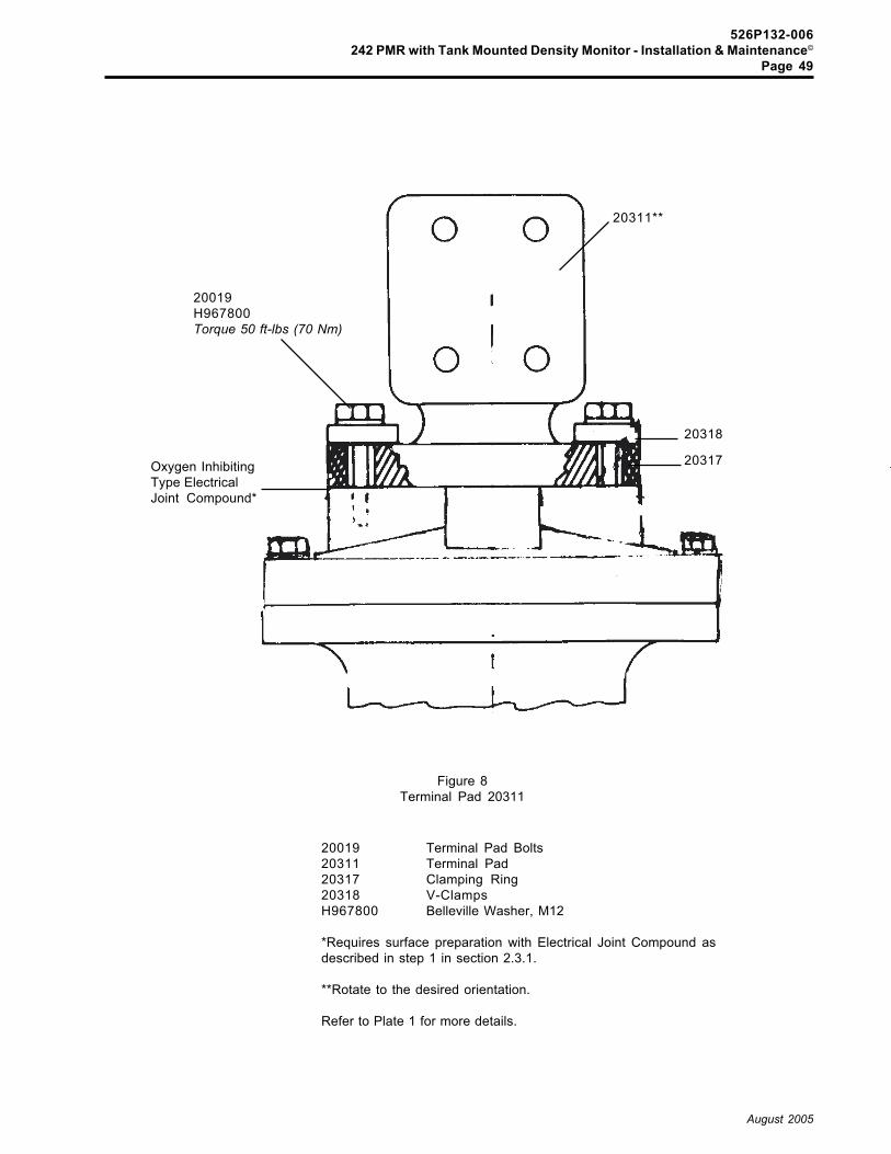
526P132-006242 PMR with Tank Mounted Density Monitor - Installation & Maintenance©
Page 49
August 2005
20311**
20317
20318
Oxygen InhibitingType ElectricalJoint Compound*
Figure 8Terminal Pad 20311
20019 Terminal Pad Bolts20311 Terminal Pad20317 Clamping Ring20318 V-ClampsH967800 Belleville Washer, M12
*Requires surface preparation with Electrical Joint Compound asdescribed in step 1 in section 2.3.1.
**Rotate to the desired orientation.
Refer to Plate 1 for more details.
20019H967800Torque 50 ft-lbs (70 Nm)

526P132-006242 PMR with Tank Mounted Density Monitor - Installation & Maintenance©
Page 50
August 2005
10032
9000290002
10008
10017
FS-1292*
FS-1292*
10151 or10159 or10160
2001020009
10037
FS-1292*
H420A6401210070***FS-1292* to flangeand bolt threads**
90003
20001
1005210015
H420A6401210071***FS-1292* to flangeand bolt threads**
* Apply Dow Corning FS-1292 Grease to all flange surfaces outside of the O-ring groove to preventcorrosion.
** Apply Dow Corning FS-1292 Grease to bolt threads
*** Unless otherwise indicated, torque as per Tables 2a/b
**** Prepare sliding surfaces as per Supplement 1 sheet at the end of this module.
***** Apply Dow Corning FS-1292 Grease on O-Rings prior to insertion.
30052****
10091
Figure 9Pole Unit Assembly (Left, Center, or Right)
10047 or 10048 or 10049
10095***
10069***H420A64012***
30000 or30121 or30122
10096
10072***Tighten this bolt enough tocenter the interrupter. Do notovertighten this bolt.
10071***H420A64012FS-1292* to flangeand bolt threads**
20018H420A60016Loctite 24210154
View AFor Tank MountedDensity Monitor

526P132-006242 PMR with Tank Mounted Density Monitor - Installation & Maintenance©
Page 51
August 2005
Figure 9Pole Unit Assembly (Left, Center, or Right)
10047 or 10048 or 10049
10008 Desiccant Bag10015 Pole Tank10017 Rupture Disk10032 Rear Tank Cover Assembly10037 Cover10047 Left Pole Unit Assembly10048 Center Pole Unit Assembly10049 Right Pole Unit Assembly10052 Tank Half10069 Bushing Top Flange Bolts10070 Bushing Bottom Flange Bolts10071 Tank End Bolts10072 Rupture Disk Bolts10091 Tank Half (with Rupture Disk)10095 Desiccant Bag Cover Screws10096 Tank End Alignment Pin10151 Bellcrank Assembly (Center)10154 Quick Gas Disconnect Valve (Malmquist)10159 Bellcrank Assembly (Left)10160 Bellcrank Assembly (Right)10196 Malmquist Mounting Bolt20001 Bushing Conductor20009 Front Bushing Assembly20010 Rear Bushing Assembly20018 Bushing Conductor Bolt30000 Interrupter Unit (Center)30052 Plug-in Connection30121 Interrupter Unit (Left)30122 Interrupter Unit (Right)90002 O-Ring, Tank End90003 O-Ring, Bottom Flange90022 Vacuum/Fill Valve O-RingH420A60016 Flat Washer, M16H420A64008 Flat Washer, M8H420A64012 Flat Washer, M12
View AFor Tank MountedDensity Monitor1015410196***
90022*****H420A64008
Groove(indicates that this fitting isself-sealed when visible)

526P132-006242 PMR with Tank Mounted Density Monitor - Installation & Maintenance©
Page 52
August 2005
Cross Sectional View
FS-1292Grease
10036
Figure 10Rupture Disk Cover Assembly
10017 Rupture Disk10036 Rupture Disk Holding Ring10072 Rupture Disk Bolts90035 Rupture Disk O-RingH420A64012 Flat Washer, M12
*Make sure that the rupture disk is centered over the60 mm hole before tightening the bolts 10072.
10017* 60 mm Hole
FS-1292 to boltthreadsTorque to 50 ft-lbs
10072H420A64012
90035

526P132-006242 PMR with Tank Mounted Density Monitor - Installation & Maintenance©
Page 53
August 2005
QuickDisconnectGas Valve10154
QuickDisconnectGas Valve10154
Figure 11aSF6 Gas System with Disconnect Gas Valve
(see Figure 11b for closeup details)
Gas Manifoldfor Bellcrank
10237
QuickDisconnectGas Valve10154
QuickDisconnectGas Valve10154
Gas Manifoldfor Tanks
10238(located behind
cabinet)
242 PMR with singletank-mounted gas density
monitor
242 PMR with threetank-mounted gas density
monitors

526P132-006242 PMR with Tank Mounted Density Monitor - Installation & Maintenance©
Page 54
August 2005
T13481FS-1292Grease
For pole units not to be removed orisolated, loosen this nut until thegroove is visible (Detail B).
The gas will remain sealed withinthe pole unit at normal pressure.When this nut is tightened, thegas will flow through the gas mani-fold. This nut must be tight duringnormal operation.
Quick Disconnect Gas Valve10154
Groove(indicates that this fitting isself-sealed when visible)
Detail B
Detail A
Detail C
Completely loosening the nutand removing the Malmquistadapter T13481 will break theseal of the manifold or gauge,and allow access to the valvefor reclaiming or refilling pur-poses (See Section 3).
10154Quick Disconnect
Gas Valve(detail)Bellcrank
Assembly(detail)
FS-1292Grease
60023SF6 Gas Density GaugeNote: Remove during Gas
Charging
10154Quick
DisconnectGas Valve
Groove(indicates that this fitting isself-sealed when visible)
FS-1292Grease
Figure 11bSF6 Gas System with Disconnect Gas Valve
(Details of the valve and its operation)
ManifoldTubing

526P132-006242 PMR with Tank Mounted Density Monitor - Installation & Maintenance©
Page 55
August 2005
10209 &10205
10208
10204FS-1292Grease
FS-1292GreaseH973A06504
H800A12904
10214
10212
10221
H699A41801H973A03010H699A06034FS-1292Grease to pin
10157
10151
Unless otherwise indicated,torque all hardware as perTables 2a/b in this module.
10207Set the length of the mechanism pullrodwith the interrupter and mechanism inthe fully open position.
10151 Center Bellcrank Assembly10156 Bellcrank Shaft (Left/Right) - not shown10157 Bellcrank Shaft (Center)10204 Interphase Shaft (Left/Right)10205 Coupling10207 Mechanism Pullrod Assembly10208 Cover10209 Roll Pin10212 Linkage Access Cover10214 Rubber Boot10221 Cable Tie ClampH699A06034 Cotter PinH699A41801 PinH800A12904 Screw, 1/4-20 x 3/4-inchH973A03010 WasherH973A06504 Flat Washer, 1/4-inch
Figure 12Linkage (Front View)
10204When installing the interphase shaft, theflatter side should be closest to the centerpole unit, facing down and horizontal.

526P132-006242 PMR with Tank Mounted Density Monitor - Installation & Maintenance©
Page 56
August 2005
10174
10210FS-1292Grease
10188*H973A06504Loctite 222
10206
10230*H420A64020Loctite 242
10175
10229*H420A64016Loctite 242
Double nutsfor mountingthe mechanism
10233*H420A58008Loctite 242
*Unless otherwise indicated,torque all hardware as perTables 2a/b in this module.
Figure 13Side View of Crank, Linkage, and Pullrod
10174 Rod End, Upper10175 Rod End, Lower10188 Retaining Bolt10206 Crank10207 Mechanism Pullrod Assembly10210 Crank Wrist Pin10229 Upper Jam Nut10230 Lower Jam Nut10233 Crank BoltH420A58008 Nut, M8H420A64016 Flat Washer, M16H420A64020 Flat Washer, M20H973A06504 Flat Washer
10207Set the length of the mechanismpullrod with the interrupter and mech-anism in the fully open position.

526P132-006242 PMR with Tank Mounted Density Monitor - Installation & Maintenance©
Page 57
August 2005
T13451
Socket
1/2-inchdriveratchet
Figure 14Manual Open/Close Tool T13451

526P132-006242 PMR with Tank Mounted Density Monitor - Installation & Maintenance©
Page 58
August 2005
10172
10153
10152
10157
10156
Lubricate lightly and evenly withProAA2 Grease, sealing the edge oflip seals while rotating the shaft
1015610153
10173
Left BellcrankAssembly 10159
Right BellcrankAssembly 10160
Center BellcrankAssembly 10151
Figure 15242 PMR Bellcrank Assemblies (without Valves)
10166
10179
10162
Side View of aBellcrank Assembly
90002
10182H420A64008Loctite 242Torque as perTables 2a/b
10182H420A64008Loctite 242Torque as perTables 2a/b
Clean the sealarea; degreasemetal parts; applyFS-1292 Grease
1015310153 1016410164
10151 Bellcrank Assembly (Center)10152 Bellcrank Housing (Center)10153 Shaft Seal Assembly10156 Bellcrank Shaft (Left/Right)10157 Bellcrank Shaft (Center)10159 Bellcrank Assembly (Left)10160 Bellcrank Assembly (Right)10162 Internal Crank10164 Bearing10166 Buffer10172 Bellcrank Housing (Left)10173 Bellcrank Housing (Right)10179 Retaining Ring10182 Shaft Seal Bolts90002 Tank End O-ringH420A64008 Flat Washer, M8
Align the point centerpunch marks whenassembling thebellcrank.

526P132-006242 PMR with Tank Mounted Density Monitor - Installation & Maintenance©
Page 59
August 2005
Figure 16Shaft Seal Assembly 10153
10164 Bearing10167 Bushing10168 Gas/Vacuum Lip Seal10169 Weather Seal10170 Aluminum Spacer10180 Seal Assembly Snap Ring90005 O-Ring (Shaft Seal Assembly)
10167
10169
10164
1017010168
10180
90005 FS-1292 Grease
Pro AA2 Greaseprior to assembly
Pro AA2 Greaseprior to assembly
FS-1292 Grease to ease assembly ofO-rings and prevent twisting; wipe offexcess grease.

526P132-006242 PMR with Tank Mounted Density Monitor - Installation & Maintenance©
Page 60
August 2005
101511015910160
10161
10163
30150H973A03004
3005130106
30032
10151 Bellcrank Assembly (Center)10159 Bellcrank Assembly (Left)10160 Bellcrank Assembly (Right)10161 Connecting Pin10163 Connector Arm30032 Operating Pullrod30051 Support Tube30106 Pullrod Coupling30150 Connector Arm Bolt30195 Jam Nut30210 Operating Pullrod Jam NutH973A03004 Flat Washer, 1/4-inch
Figure 17Bellcrank Linkage to Interrupter Unit
30195
30210

526P132-006242 PMR with Tank Mounted Density Monitor - Installation & Maintenance©
Page 61
August 2005
Notice: Be sure to install the CTs with the polaritymarks and white dot facing upward.
70000
70010*H673A05907H973A04503HNB335050P609 (two)Loctite 242
70002
70001
70004
7000370009H673A09102H420A64008
Apply FS-1292Grease to flange
10070H420A64012Apply FS-1292Greaseto bolt threads
70011*H673A05909H973A04501H420A64012Loctite 242
*Torque and apply Loctite as per Tables 2a/b in this module
7000770005
70006
Figure 18Current Transformer 70000
10070 Bushing Bottom Flange Bolts70000 Current Transformer70001 CT Protective Cover70002 Insulating Seal70003 Bottom Support70004 Mounting Bracket70005 Bottom Pressboard Spacer70006 Vertical Pressboard Spacers70007 Inter CT Pressboard Spacers70009 CT Cover Bolts
70010 Upper Bracket Mounting Bolts70011 Lower Bracket Mounting BoltsH420A64008 Flat Washer, M8 (Two)H420A64012 Flat Washer, M12H673A05907 Nut, 3/8-16H673A05909 Nut, 1/2-13-inchH673A09102 Nut, 5/16-18H973A04501 Lock Washer, 1/2-inchH973A04503 Lock Washer, 3/8-inchHNB335050P609 Flat Washer, M10
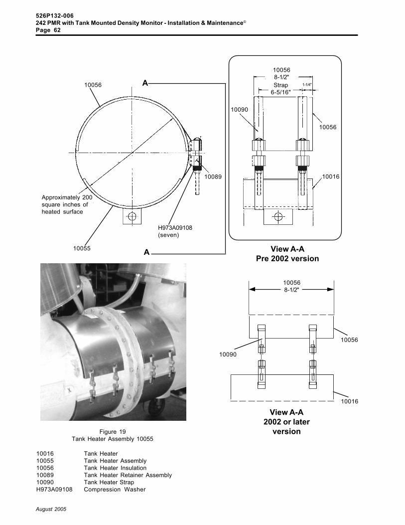
526P132-006242 PMR with Tank Mounted Density Monitor - Installation & Maintenance©
Page 62
August 2005
10089
Approximately 200square inches ofheated surface
10055
H973A09108(seven)
10056 A
A
10016 Tank Heater10055 Tank Heater Assembly10056 Tank Heater Insulation10089 Tank Heater Retainer Assembly10090 Tank Heater StrapH973A09108 Compression Washer
Figure 19Tank Heater Assembly 10055
10016
10056
10090
100568-1/2"Strap
6-5/16"1-1/4"
View A-APre 2002 version
View A-A2002 or later
version
10016
10056
10090
100568-1/2"

526P132-006242 PMR with Tank Mounted Density Monitor - Installation & Maintenance©
Page 63
August 2005
Figure 20Guide Piston Dimension for HMB Hydraulic Mechanisms
54040
54045
Gui
de P
isto
nD
imen
sion
114
mm
atta
ined
by
turn
ing
guid
e pi
ston
up
ordo
wn
Cotter Pin A
54040 Guide Piston54045 Piston Pin
For breakers equipped with an HMB hydraulicmechanism, a guide piston screws 54040 (Fig.14) screws on top of the mechanism pullrod. Avery important length 114 mm, between the centerof the piston pin 54045 and the mechanism topplate must be attained to ensure proper opera-tion. This length is attained by removing coter pinA and turning the screw-on guide piston up ordown as needed. Re-install the cotter pin afterattaining the dimension.

526P132-006242 PMR with Tank Mounted Density Monitor - Installation & Maintenance©
Page 64
August 2005
Figure 21Density Monitor Installation to Tank
Supplied on FrameMounted toCabinet
60441SF6 Gas Density Monitor
10154Quick Disconnect Gas Valve
Caplug