02 - 09 - Aktuality - LDM · 02 - 09.3 01.18.GB Control and shut-off valves ... Socket Weld 1/2" -...
81
® -1- 02 - 09.3 01.18.GB Control and shut-off valves CV 300
Transcript of 02 - 09 - Aktuality - LDM · 02 - 09.3 01.18.GB Control and shut-off valves ... Socket Weld 1/2" -...

®
-1-
02 - 09.301.18.GB
Control and shut-off valvesCV 300
®
-2-
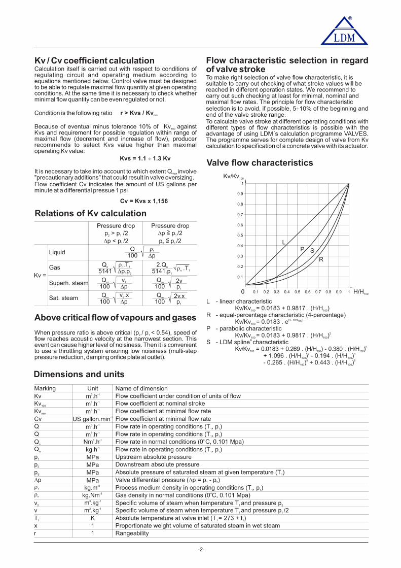
L - linear characteristicKv/Kv = 0.0183 + 0.9817 . (H/H )100 100
R - equal-percentage characteristic (4-percentage)Kv/Kv = 0.0183 . e100
(4 . H/H100)
P - parabolic characteristicKv/Kv = 0.0183 + 0.9817 . (H/H )100 100
2
S - LDM spline characteristic®
Kv/Kv = 0.0183 + 0.269 . (H/H ) - 0.380 . (H/H )100 100 100
2
+ 1.096 . (H/H ) - 0.194 . (H/H )100
3
100
4
- 0.265 . (H/H ) + 0.443 . (H/H )100
5
100
6
Kv/Kv100
H/H1000
LP
R
S
1
0.9
0.8
0.7
0.6
0.5
0.4
0.3
0.2
0.1
0.1 0.2 0.3 0.4 0.5 0.6 0.7 0.8 0.9 1
Kv coefficient calculation/ CvCalculation itself is carried out with respect to conditions ofregulating circuit and operating medium according toequations mentioned below. Control valve must be designedto be able to regulate maximal flow quantity at given operatingconditions. At the same time it is necessary to check whetherminimal flow quantity can be even regulated or not.
Condition is the following ratio
Because of eventual minus tolerance 10% of Kv against100
Kvs and requirement for possible regulation within range ofmaximal flow (decrement and increase of flow), producerrecommends to select Kvs value higher than maximaloperating Kv value:
It is necessary to take into account to which extent Q involvemax
"precautionary additions" that could result in valve oversizing.Flow coefficient Cv indicates the amount of US gallons perminute at a differential pressue 1 psi
r > Kvs / Kvmin
Kvs = 1.1 1.3 Kv�
Relations of Kv calculation
Flow characteristic selection in regardof valve strokeTo make right selection of valve flow characteristic, it issuitable to carry out checking of what stroke values will bereached in different operation states. We recommend tocarry out such checking at least for minimal, nominal andmaximal flow rates. The principle for flow characteristicselection is to avoid, if possible, 5 10% of the beginning and�end of the valve stroke range.To calculate valve stroke at different operating conditions withdifferent types of flow characteristics is possible with theadvantage of using LDM´s calculation programme VALVES.The programme serves for complete design of valve from Kvcalculation to specification of a concrete valve with its actuator.
Above critical flow of vapours and gases
When pressure ratio is above critical (p / p < 0.54), speed of2 1
flow reaches acoustic velocity at the narrowest section. Thisevent can cause higher level of noisiness. Then it is convenientto use a throttling system ensuring low noisiness (multi-steppressure reduction, damping orifice plate at outlet).
Dimensions and units
Valve flow characteristics
Pressure drop Pressure dropp > p /22 1
�p < p /21
�p p /21
p p /22 1
=>
=<
Qn
5141�n 1.T�p.p2
� 2.Qn
5141.p1
�n 1.T�
Qm
100v2
�p� Qm
1002vp1
�Qm
1002v.xp1
�Qm
100v .x2
�p�
Kv =
Liquid
Gas
Superh. steam
Sat. steam
Q100
�1
�p�
Marking UnitFlow coefficient under condition of units of flowKv
Flow rate in operating conditions (T , p )1 1QFlow rate in normal conditions (0 C, 0.101 Mpa)oQn Nm .h3 -1
Flow rate in operating conditions (T , p )1 1Qm kg.h-1
Name of dimension
p1 MPa Upstream absolute pressurep2 MPa Downstream absolute pressurepS MPa Absolute pressure of saturated steam at given temperature (T )1
�p MPa Valve differential pressure ( p = p - p )� 1 2
�1 kg.m-3 Process medium density in operating conditions (T , p )1 1
�n kg.Nm-3 Gas density in normal conditions (0 C, 0.101 Mpa)v2 m .kg3 -1 Specific volume of steam when temperature T and pressure p1 2
v m .kg3 -1 Specific volume of steam when temperature T and pressure p /21 1
T1 K Absolute temperature at valve inlet (T = 273 + t )1 1
xr
11
Proportionate weight volume of saturated steam in wet steamRangeability
Flow coefficient at minimal flow rateKvmin
Flow coefficient at minimal flow rateCv
m .h3 -1
m .h3 -1
US gallon.min-1
m .h3 -1
o
Flow coefficient at nominal strokeKv100 m .h3 -1
Flow rate in operating conditions (T , p )1 1Q m .h3 -1
Cv = Kvs x 1,156
®
-3-
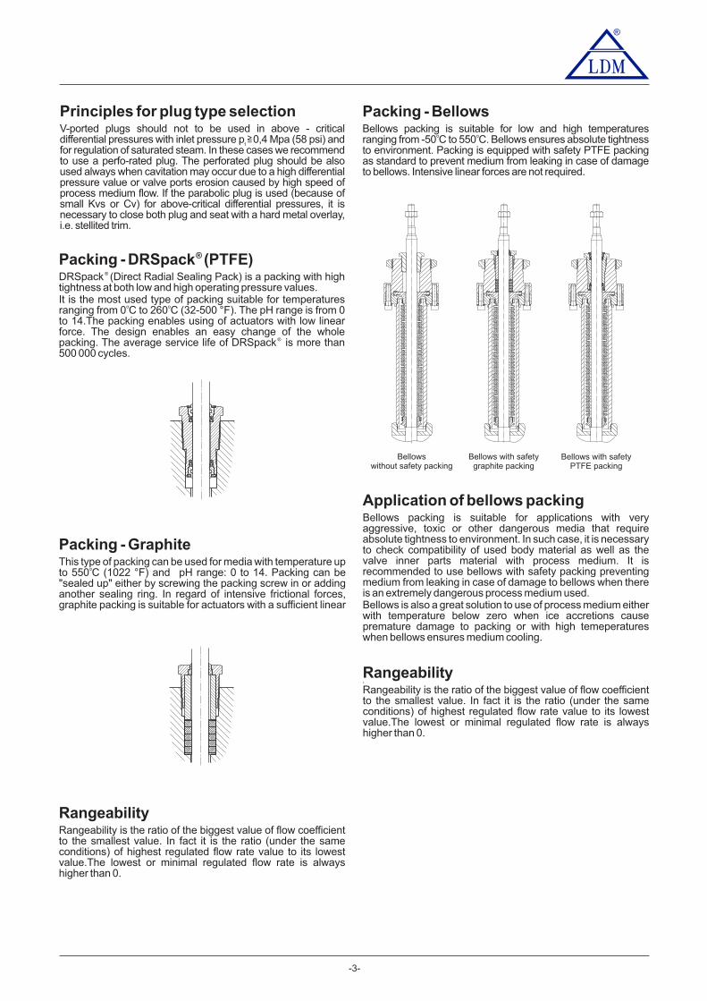
Packing - DRSpack (PTFE)®
DRSpack (Direct Radial Sealing Pack) is a packing with high®
tightness at both low and high operating pressure values.It is the most used type of packing suitable for temperaturesranging from 0 C to 260 C . The pH range is from 0o o (32-500 °F)to 14.The packing enables using of actuators with low linearforce. The design enables an easy change of the wholepacking. The average service life of DRSpack is more than®
500 000 cycles.
Principles for plug type selectionV-ported plugs should not to be used in above - criticaldifferential pressures with inlet pressure p 0,4 Mpa and(58 psi)for regulation of saturated steam. In these cases we recommendto use a perfo-rated plug. The perforated plug should be alsoused always when cavitation may occur due to a high differentialpressure value or valve ports erosion caused by high speed ofprocess medium flow. If the parabolic plug is used (because ofsmall Kvs ) for above-critical differential pressures, it isor Cvnecessary to close both plug and seat with a hard metal overlay,i.e. stellited trim.
1>=
Packing - GraphiteThis type of packing can be used for media with temperature upto 550 C and pH range: 0 to 14. Packing can beo (1022 °F)"sealed up" either by screwing the packing screw in or addinganother sealing ring. In regard of intensive frictional forces,graphite packing is suitable for actuators with a sufficient linear
RangeabilityRangeability is the ratio of the biggest value of flow coefficientto the smallest value. In fact it is the ratio (under the sameconditions) of highest regulated flow rate value to its lowestvalue.The lowest or minimal regulated flow rate is alwayshigher than 0.
Rangeability2
Rangeability is the ratio of the biggest value of flow coefficientto the smallest value. In fact it is the ratio (under the sameconditions) of highest regulated flow rate value to its lowestvalue.The lowest or minimal regulated flow rate is alwayshigher than 0.
Bellowswithout safety packing
Bellows with safetygraphite packing
Bellows with safetyPTFE packing
Packing - BellowsBellows packing is suitable for low and high temperaturesranging from -50 C to 550 C. Bellows ensures absolute tightnesso o
to environment. Packing is equipped with safety PTFE packingas standard to prevent medium from leaking in case of damageto bellows. Intensive linear forces are not required.
Application of bellows packingBellows packing is suitable for applications with veryaggressive, toxic or other dangerous media that requireabsolute tightness to environment. In such case, it is necessaryto check compatibility of used body material as well as thevalve inner parts material with process medium. It isrecommended to use bellows with safety packing preventingmedium from leaking in case of damage to bellows when thereis an extremely dangerous process medium used.Bellows is also a great solution to use of process medium eitherwith temperature below zero when ice accretions causepremature damage to packing or with high temeperatureswhen bellows ensures medium cooling.

®
CV / SV 3x0
-4-
Control and shutt-off valvesNPS ½"- 16" Class 150, 300 and 600
CV / SV 320 (Ex) CV / SV 330 (Ex)Two-way, single-seated, control valve(shut-off)
Class 300 and 600 (Class 150, 300 and 600 weld ended)Cast steel
A351 CFM81.4571 / 17 348.4
1.4027 / 42 2906.5
1.4581 / 42 2941.4
Stainless steel
1.4028 / 17 023.6
1.4027 / 42 2906.5
-10 to 550 °C (14 až 1020 °F)
NPS 1/2" to 16"
1.4571 / 17 348.41.4021 / 17 022.6
RF (Raised Face), RTJ (Ring Joint Face), LFF (Large Female Face), SFF (Small Female Face),LGF (Large Groove Face), SGF (Small Groove Face)
1.4021 / 17 027.61.4581 / 42 2941.4
-10 to 550 °C (14 to 1020 °F)Face to face dimensions
Packing
Type of plugFlow characteristicKvs valueLeakage rate
Leakage rate for Ex version
Connection flanges
0.01 to 1600 m /hour (0,012 to 1850 US galon/min)3
Rate C acc. to ISO 5208:2008
DRSpack (PTFE) t = 260 °C (500 °F), Exp. graphite t = 550 °C (1020 °F), Bellows (DN 15-150) t = 550 °Cmax®
max max
Rangeability r 50 : 1
SeriesType of valveNominal size rangeNominal pressureBody material
Seat material:DIN W.Nr./+ČSNPlug material:DIN W.Nr./+ČSN
Operating temperature range
V-ported, contoured, perforatedLinear, equal-percentage, LDMspline , parabolic, on - off�
Class III. acc. to ANSI/FCI 70-2-2013 (<0,1% Cv) for control valves with metal-metal seat sealing
Class IV. dle ANSI/FCI 70-2-2013 (<0.01% Cv) for shut off valve
Technical data
Flange facesAcc. to ASME B16.5-2013
DescriptionControl valves V / V 20 (Ex) 0 [(furtherC S 3 and C S 33V / V (Ex)only x0 )] are single-seated valves designed forC S 3V / V (Exregulation and shut-off of process medium flow. In regard of agreat variety of used actuators, the valves are suitable forregulation at low as well as high differential pressures in adiversity of operating conditions. Flow characteristics, Kvs andCv values and leakage rates correspond to internationalstandards.Valves x0 areC S 3V / V (Ex) are equipped with hand wheel orespecially designed for electro-mechanic actuators of thefollowing producers: ZPA Nová Paka, Regada, ZPA Pečky,Schiebel,Auma, Rotork or for pneumatic actuators Flowserve.
ApplicationThe valves series CV / SV 3x0 are designed for applications inheating, ventilation, power generation and chemicalprocessing industries. The valves CV / SV 3x0 Ex meet therequirements II 1/2G IIB TX acc.to ČSN-EN 13463-1 (6/2009)and ČSN EN 1127-1 (5/2008), and in connection with suitableactuators, they are also designed for applications in gas andchemical industries. Valve body can be optionally made of caststeel or stainless steel.The materials selected correspond to recommendationsstipulated by ČSN-EN 1 -1ASME B16.34-2013 or 2516(1/200 ). The maximal permissible operating pressures in6behaviour with types of material and temperature are specifiedin the table on page of this catalogue.80
Process mediaValves series CV / SV 3x0 are designed for regulation (CV 3x0)and shut-off (SV 3x0) of flow and pressure of liquids, gases andvapours without abrasive particles e.g. water, steam, air andother media compatible with material of the valve body and innerparts. The valves series CV / SV 3x0 Ex are also designed forcontrol and shut-off of the flow and pressure of technical and fuelgases and inflammable liquids. To ensure a reliable regulation,the producer recomends to pipe a strainer in front of the valveinto pipeline or ensure in any other way that process mediumdoes not contain abrasive particles or impurities.
InstallationThe valve be piped the way so that the direction ofmustmedium flow will coincide with the arrows on the body.valveThe valve can be installed in any position except position whenthe actuator is under the valve body. When mediumtemperature exceeds 150°C (300°F), it is necessary to protectthe actuator against glowing heat from the pipeline e.g. by themeans of proper insulating of the pipeline and valve or by tiltingthe valve away from the heat radiation.Detailed informations are given in the instruction for installation andservice.
acc. to ISA-75.08.01-2002 /R2007) for flange connection, acc. to ISA-75.08.05-2002 (R2007) for weld ended execution
A216 WCC, A217 WC9NPS /2" 2"1 -NPS 3" - 16"
NPS 3" - 6"NPS 8" - 16"
NPS /2" 2"1 - 1.4571 / 17 348.4
Weld ends Butt Weld 1/2" - 16" acc. to ASME B16.25-2012; Socket Weld 1/2" - 2" acc. to ASME B16.11-2011
Class IV. acc. to ČSN EN 1349 (7/2010) (<0.01% Cv) for control valves with metal-PTFE seat sealing

®
-5-
Cv (Kvs) Δp [psi]maxvalues and differential pressures [MPa],of valves NPS ½" - 16" with countoured and V -ported plugsflow direction below plug) with electro-mechanic actuators
Kvs [m /hour]3
1
---
4.01)
H 2 3 4 5
---
--- ---
---
6
--- --- --- --- ---
7
---
EPK EPJ
Zepadyn 670
ENC
6,3 kN
MIDI 660
ENB
packinggraphite
10PTFE
10
4 kN
8
---
---
9
---
---
ST 1 ExST 0Auma
EA...
5 kN
Δp value is the valve max. differential pressure when maxmax
open - close function is always guaranteed.Differential pressure must not exceed 2,0 MPa (290 psi) forvalves Class 150 and 5,0 MPa (750 psi) for valves Class 300.
In regard of service life of seat and plug, it is recommended sothat permanent differential pressure would not exceed 1.6MPa / 232 psi. Otherwise it is suitable to use perforated plug( p up to 4,0 MPa / 580 psi) or sealing surfaces of seat andΔplug with a hard metal overlay ( p up to 2,5 MPa / 363 psi).Δ
Ds
3
6
15
8
12
---
---
--- --- --- 0.163)
---
---
---
---
--- 0.1...0.013)
NPS
½”
EPLEZ...
EPL
ST 0.1Schiebel
ST 0.1
packing packingPTFE PTFE
Cv [US galon/min][mm] [mm]
Δpmax [psi][MPa]
0.183)
0.116...0.0123) 14501450
10 1014501450
10 1014501450
10 1014501450
10 1014501450
10 1014501450
10 1014501450
10 1014501450
10 1014501450
6,42 10905 1450
6,42 10905 1450
10 1014501450
3,05 10442 1450
8,91 1012931450
10 1014501450
--- ---
--- ---
--- ---
--- --- --- --- ---
10 10
---
---
3
6
15
8
12
--- --- --- ---
---
---
---
---
--- 0.16...0.013)
1”
0.18...0.0123)14501450
10 1014501450
10 1014501450
10 1014501450
10 1014501450
10 1014501450
10 1014501450
10 1014501450
10 1014501450
6,24 10905 1450
6,42 10905 1450
10 1014501450
3,05 10442 1450
8,91 1012931450
10 1014501450
0.251)
0.291)
4.621)
2.51)
2.89
1.61)
1.85------
--- 1.01)
1.16
0.631)
0.73
0.41)
0.46
--- --- --- --- ------
25
201,38 7,66200 1111
4,33 10628 1450
8,16 1011841450
0,77 4,66111 675
2,59 6,48376 940
4,97 8,86720 1285
--- --- --- --- --- --- ------
10.011.6
6.34)
7.284)
6.32)
7.282)
4.04)
4.624)
4.01)
4.621)
2.51)
2.891)
1.61)
1.851)
1.01)
1.161)
0.631)
0.731)
0.41)
0.461)
---
0.251)
0.291)
---
--- ---
---
--- --- --- ---
--- --- --- --- --- ---6
15
8
12
---
1½”
10 1014501450
10 1014501450
10 1014501450
10 1014501450
10 1014501450
10 1014501450
6,24 10905 1450
6,42 10905 1450
10 1014501450
3,05 10442 1450
8,91 1012931450
10 1014501450
40
201,38 7,66200 1111
4,33 10628 1450
8,16 1011841450
0,19 1,7028 247
0,90 2,42131 350
1,83 3,34265 484
2528,9
1618.5
1011.6
2.51)
2.891)
1.61)
1.851)
1.01)
1.161)
0.631)
0.731)
0.41)
0.461)
--- ---
---
---
---
---
--- ---
---
--- ---
--- ---
--- ---
--- --- ---
--- --- ---
--- --- ---
--- --- ---
--- --- ---
--- --- ---
--- --- ---
--- --- ------
--- ---
6.34)
7.284)
4.04)
4.624)
6.32)
7.282)
--- --- ------
------ ---
------ ---
---
---
--- --- --- ---
0.251)
0.291)
4.01)
4.621)
--- --- --- ------ ---
--- --- --- ------ ---
--- --- --- ------ ---
--- ---
500,07 0,9810 142
0,50 1,4072 240
1,05 1,96152 284
4046.2
2528,9
1618.5
1011.6
6.34)
7.284) --- --- --- ------ ---2”
16
---
---
Actuating (actuator)
Marking in valve specification No.
Linear force
For further information onactuating, see actuators´catalogue sheets
Note: The table continues on the next page
1) parabolic plug2) andV-ported plug with linear characteristic, parabolic plug with equal-percentage LDMspline
®
3) Kvs = 0,16; 0,1; 0,063; 0,04; 0,025; 0,016; 0,01valve with micro-throttling trim. Execution with / Cv = 0,18; 0,11; 0,073; 0,046; 0,029; 0,018; 0,0114) V-ported plug with linear characterictic onlyMax. differential pressures specified in table apply to PTFE and graphite packing.
for bellows must be consulted with the producer.Δpmax
EQL EQL
CVL-1000 CVL-1500
graphite graphite
Δpmax [psi][MPa] Δpmax [psi]
[MPa]

®
-6-
Kvs [m /hour]3
Actuating (actuator)
1
---
4.01)
Marking in valve specification No.
2 3 4 5
---
--- ---
---
6
--- --- --- --- ---
Linear force
7
---
packinggraphite
10PTFE
108
---
---
9
---
---
3
6
15
8
12
---
---
--- --- --- 0.163)
---
---
---
---
--- 0.1...0.013)
NPS
½”
packingPTFE
Rxx
Hand wheel
PTFE PTFE
packing packingCv [US galon/min]
Δpmax [psi] Δpmax [psi] Δpmax [psi] Δpmax [psi]
0.183)
0.12...0.0123) 14501450
10 1014501450
10 1014501450
10 1014501450
10 1014501450
10 1014501450
10 1014501450
10 1014501450
10 1014501450
101014501450
101450
10 1010145014501450
101014501450
101450
10 1010145014501450
--- ---
--- ---
--- ---
--- --- --- --- ---
10 10
---
---
3
6
15
8
12
--- --- --- ---
---
---
---
---
--- 0.16...0.013)
1”
0.18...0.0123)14501450
10 1014501450
10 1014501450
10 1014501450
10 1014501450
10 1014501450
10 1014501450
10 1014501450
10 1014501450
101010 101010145014501450 145014501450
101010 101010145014501450 145014501450
0.251)
0.291)
4.621)
2.51)
2.89
1.61)
1.85------
--- 1.01)
1.16
0.631)
0.73
0.41)
0.46
--- --- --- --- ------
25
20101010 101010
145014501450 145014501450
10381010 1010
14501450 14501450
--- --- --- --- --- --- ------
10.011.6
6.34)
7.284)
6.32)
7.282)
4.04)
4.624)
4.01)
4.621)
2.51)
2.891)
1.61)
1.851)
1.01)
1.161)
0.631)
0.731)
0.41)
0.461)
---
0.251)
0.291)
---
--- ---
---
--- --- --- ---
--- --- --- --- --- ---6
15
8
12
---
1½”
1010
7,16
1010
10
14501450 14501450
1450
10 1014501450
1010 101014501450 14501450
10 1014501450
1010 10101450145014501450
10 1014501450
1010 10101450145014501450
10 1014501450
40
201010 1010
145014501450145010 10
14501450
2,68 4,19388 608
4,454,45 5,975,97646646 866866
2528,9
1618.5
1011.6
2.51)
2.891)
1.61)
1.851)
1.01)
1.161)
0.631)
0.731)
0.41)
0.461)
--- ---
---
---
---
---
--- ---
---
--- ---
--- ---
--- ---
--- --- ---
--- --- ---
--- --- ---
--- --- ---
--- --- ---
--- --- ---
--- --- ---
--- --- ------
--- ---
6.34)
7.284)
4.04)
4.624)
6.32)
7.282)
--- --- ------
------ ---
------ ---
---
---
--- --- --- ---
0.251)
0.291)
4.01)
4.621)
--- --- --- ------ ---
--- --- --- ------ ---
--- --- --- ------ ---
--- ---
501,56 2,47226 358
2,632,63 3,533,53381381 512512
4046.2
2528,9
1618.5
1011.6
6.34)
7.284) --- --- --- ------ ---2”
16
---
---
Auma
EA...
7.5 kN
Auma
EA...
10 kN
Schiebel
EZ...
ST 1
EPI
Schiebel
EZ...
ST 1
EPI
Zepadyn 670
ENC
Modact MTR
EPD
EYB
Modact Cont.
EYA
15 kN
Modact MTN
EA...
AumaSchiebel
EZ...
689 821
4.75 5.66
---
---
---
---
---
---
---
---
---
---
---
---
---
---
---
---
---
---
---
---
---
---
---
---
---
---
---
---
---
---
---
---
---
---
---
---
H Ds[mm] [mm]
For further information onactuating, see actuators´catalogue sheets
1) parabolic plug2) andV-ported plug with linear characteristic, parabolic plug with equal-percentage LDMspline
®
3) Kvs = 0,16; 0,1; 0,063; 0,04; 0,025; 0,016; 0,01valve with micro-throttling trim. Execution with / Cv = 0,18; 0,11; 0,073; 0,046; 0,029; 0,018; 0,0114) V-ported plug with linear characterictic only
Note: The table continues on the next page
IQM 10
EQ...
IQM 10
EQ...
IQM 10
EQ...
graphite graphite graphite
Max. differential pressures specified in table apply to PTFE and graphite packing.for bellows must be consulted with the producer.Δpmax

-7-
Actuating (actuator)
Marking in valvespecification No.
Linear force
For furtherinformation onactuating, seeactuators´catalogue sheets
EZ... EYB
Modact Cont.
EYA
Auma
EA...
15 kN
Modact MTNSchiebelZepadyn
ENC
EPIEPD
ST 1Modact MTR
Auma
IQM 10Schiebel
EZ...EQ...
packing
7.5 kN 10 kN
packing packing packing
10 kN
EZ...
Auma
EA...
16 kN
SchiebelST 1
IQM 10
packing
1 2 3 4 5
80
100
150
NPS
6"
graphitePTFE
3"
4" 40
100116
6372.8
4046.2
2528.9
1618.5
160185
100116
6372.8
4046.2
252 98.
360416
250289
160185
100116
6372.8
0.16 0.4523 65
0.45 0.7465 108
0.45 0.7465 108
1.03 1.32150 192
EPM
Modact MTR
EPD
ST 2
CVL-5000
ENEEQL
Zepadyn
1.15 1.44167 209
0.28 0.7341 106
0.73 1.18106 171
0.73 1.18106 171
1.63 2.08236 302
1.81 2.26263 328
0.05 0.187 26
0.18 0.3126 45
0.18 0.3126 45
0.44 0.5864 83
0.50 0.6372 91
packing
Ruční kolo
Rxx
1.15 1.44167 209
1.81 2.26263 328
0.50 0.6372 91
Kvs [m /hour]3
Cv [US galon/min]
Δpmax [psi]
H Ds[mm] [mm]
EA...EPIEQ...
Δpmax [psi] Δpmax [psi] Δpmax [psi] Δpmax [psi] Δpmax [psi]
graphitePTFE graphitePTFE graphitePTFE graphitePTFE graphitePTFE
Max. differential pressures specified in table apply to PTFE and graphite packing.for bellows must be consulted with the producer.Δpmax
Note: The table continues on the next page

®®
-8-
EYB
Modact Cont.
EYA
15 kN
Modact MTN
EA...
AumaSchiebelIQM 10
EZ...EQ...
packing
16 kN
packing
80
100
1506"
3"
4" 40
100116
6372 8.
4046.2
2528.9
1618.5
160185
100116
6372.8
4046.2
2528.9
360416
250289
160185
100116
6372.8
1,62 1,91234 277
2,20 2,49319 361
1.03 1.32150 192
EPM
Modact MTR
EPD
ST 2
CVL-5000
ENEEQL
Zepadyn 671*)
1.15 1.44167 209
2,53 2,98367 432
3,43 3,88498 563
1.63 2.08236 302
1.81 2.26263 328
0,71 0,84103 122
097 1,11141 160
0.44 0.5864 83
0.50 0.6372 91
0.36
0.21
0.21
0.21
0.51
0.39
0.39
0.39
52
31
31
31
74
56
56
56
0.41
0.27
0.27
0.27
0.56
0.44
0.44
0.44
60
39
39
39
82
64
64
64
0.85 1.19124 173
0.97 1.31141 190
0.19
0.11
0.11
0.11
0.28
0.20
0.20
0.20
27
15
15
15
11
11
8
8
4
40
30
30
30
21
21
18
18
9
0.22
0.14
0.14
0.14
0.31
0.24
0.24
0.24
32
20
20
20
14
14
11
11
5
44
34
34
34
25
25
21
21
11
--- ---
--- ---
--- ---
Kvs [m /hour]3
EZ...
Modact MTRAuma
EA...
Modact MTNSchiebel
EA...
EQ...ENEEZ...
Zepadyn 671*) Modact Cont.
20 kN 25 kN
packing packing packing
32 kN
EYAEPD
EYB
1 2 3 4 5
150
200
200
200
100
150
150
150
NPS
200
230
230
250
250
330
---
---
---
---
---
---
---
---
---
---
---
---
---
---
---
---
---
---
---
---
---
---
---
---
---
---
---
---
---
---
250289
462
728
160185
289
462
462
100116
185
289
289
8"
10"
12"
16"
80
80
80
100
400462
728
925
728
570659
925
1160
1160
1850
1.15 1.44167 209
1.81 2.26263 328
0.50 0.6372 91
packing
Ruční kolo
Rxx
0.95
0.87
0.87
0.87
1.03
0.97
0.97
0.97
137
126
126
126
95
95
80
80
45
150
141
141
141
106
106
89
89
50
1.69
1.56
1.56
1.56
1.85
1.74
1.74
1.74
245
227
227
227
268
252
252
252
3.81 4.15553 602
ST 2ST 2CVL-5000
IQM12
EPMEPMEQLEQ...
Auma
IQM 20Schiebel
0,70
0,62
0,62
0,62
0,79
0,72
0,72
0,72
102
91
91
91
68
68
57
57
32
115
105
105
105
79
79
66
66
37
1.27
1.13
1.13
1.13
1.42
1.31
1.31
1.31
183
164
164
164
206
190
190
190
2.87 3.21416 465
0,49
0,41
0,41
0,41
0,58
0,51
0,51
0,51
71
60
60
60
44
44
37
37
20
84
74
74
74
55
55
46
46
25
0.89
0.75
0.75
0.75
1.05
0.93
0.93
0.93
129
109
109
109
152
135
135
135
2.04 2.38295 345
0,34
0,26
0,26
0,26
0,43
0,36
0,36
0,36
49
37
37
37
27
27
23
23
12
62
52
52
52
38
38
32
32
17
0.62
0.48
0.48
0.48
0.78
0.66
0.66
0.66
91
70
70
70
113
96
96
96
1.44 1.79210 259
---
---
--- ---
--- ---
---
---
---
---
---
---
---
---
---
---
---
---
---
---
Cv [US galon/min]
400 250
400
400
0.07
0.07
0.10
0.10
0.06
0.06 0.08
0.08
0.02 0.04
0.15
0.15
0.17
0.17
0.12
0.12 0.14
0.14
0.06 0.07
630
800
1000
630
630
160
250
250
800
1000
1600
0.47
0.47
0.39
0.39
0.22
0.54
0.54
0.46
0.46
0.25
0.26
0.26
0.38
0.38
0.32
0.32
0.17
0.22
0.22
0.12
0.19
0.19
0.30
0.30
0.25
0.25
0.14
0.16
0.16
0.08
0.65
0.65
0.55
0.55
0.31
0.73
0.73
0.61
0.61
0.35
*) max. NPS 12"
H Ds[mm] [mm]
Actuating (actuator)
Marking in valvespecification No.
Linear force
For furtherinformation onactuating, seeactuators´catalogue sheets
Δpmax [psi]Δpmax [psi]Δpmax [psi]Δpmax [psi]Δpmax [psi]Δpmax [psi]
graphitePTFE graphitePTFE graphitePTFE graphitePTFE graphitePTFE graphitePTFE
Max. differential pressures specified in table apply to PTFE and graphite packing.for bellows must be consulted with the producer.Δpmax

®
-9-
®
Cv (Kvs) Δp [psi]maxvalues and differential pressures [MPa],NPS ½" - 16" with countoured and V -ported plugsof valves
(flow direction below plug) with pneumatic actuators
Kvs [m /hour]3
1 2 3 4 5 6 7
4.8
Flowserve PA 252
1.0 - 2.122.56 - 4.8
8 9
NO NC
5.8
BFYxZA
PFA
2.0 - 4.8
6.4 kN
NPS
BDYxAA1.0 - 2.4
6.4 kN
packing packing
---
4.01)
---
--- ---
---
--- --- --- --- ---
--- ---
---
---
---
3
6
15
8
12
---
---
--- --- --- 0.163)
---
---
---
---
--- 0.1...0.013)
½”
0.183)
0.116...0.0123)
10 1014501450
10 1014501450
10 1014501450
10 1014501450
10 1014501450
10 1014501450
10 1014501450
10 1014501450
10 1014501450
10 1014501450
--- ---
--- ---
--- ---
--- --- --- --- --- ---
---
3
6
15
8
12
--- --- --- ---
---
---
---
---
--- 0.16...0.013)
1”
0.18...0.0123)
10 1014501450
10 1014501450
10 1014501450
10 1014501450
10 1014501450
10 1014501450
10 1014501450
10 1014501450
10 1014501450
10 1014501450
0.251)
0.291)
4.621)
2.51)
2. 901)
1.61)
1.851)
------
--- 1.01)
1.161)
0.631)
0.731)
0.41)
0.461)
--- --- --- --- ------
25
208.46 1012261450
8.46 1012261450
5.15 9.04747 1311
5.15 9.04747 1311
--- --- --- --- --- --- ------
10.011.6
6.34)
7.284)
6.32)
7.282)
4.04)
4.624)
4.01)
4.621)
2.51)
2. 981)
1.61)
1.851)
1.01)
1.161)
0.631)
0.731)
0.41)
0.461)
---
0.251)
0.291)
---
--- ---
---
--- --- --- ---
--- --- --- --- --- ---6
15
8
12
---
1½”
10 1014501450
10 1014501450
10 1014501450
10 1014501450
10 1014501450
10 1014501450
10 1014501450
10 1014501450
40
208.46 1012261450
8.46 1012261450
1,90 3,41275 495
1,90 3,41275 495
252 98.
1618.5
1011.6
2.51)
2. 981)
1.61)
1.851)
1.01)
1.161)
0.631)
0.731)
0.41)
0.461)
--- ---
---
---
---
---
--- ---
---
--- ---
--- ---
--- ---
--- --- ---
--- --- ---
--- --- ---
--- --- ---
--- --- ---
--- --- ---
--- --- ---
--- --- ------
--- ---
6.34)
7.284)
4.04)
4.624)
6.32)
7.282)
--- --- ------
------ ---
------ ---
---
---
--- --- --- ---
0.251)
0.291)
4.01)
4.621)
--- --- --- ------ ---
--- --- --- ------ ---
--- --- --- ------ ---
--- ---
16
Cv [US galon/min]
[psi]
15 - 35 29 - 70
15 - 31 37 - 70
70 84
---
---
H Ds[mm] [mm]
Pneumatic actuators
Marking in valve specification No.
Failure of air actionSpecification No. of actuator
Spring range
Spring setting
Feeding pressure
[bar]
[bar]
Linear force
For further information onactuating, see actuators´catalogue sheets
[bar]
[psi]
[psi]
Δp value is the valve max. differential pressure when maxmax
open - close function is always guaranteed.Differential pressure must not exceed 2,0 MPa (290 psi) forvalves Class 150 and 5,0 MPa (750 psi) for valves Class 300.
In regard of service life of seat and plug, it is recommended sothat permanent differential pressure would not exceed 1.6MPa / 232 psi. Otherwise it is suitable to use perforated plug( p up to 4,0 MPa / 580 psi) or sealing surfaces of seat andΔplug with a hard metal overlay ( p up to 2,5 MPa / 363 psi).Δ
Δpmax [psi]Δpmax [psi]
graphitePTFE graphitePTFE
Note: The table continues on the next page
1) parabolic plug2) andV-ported plug with linear characteristic, parabolic plug with equal-percentage LDMspline
®
3) Kvs = 0,16; 0,1; 0,063; 0,04; 0,025; 0,016; 0,01valve with micro-throttling trim. Execution with / Cv = 0,18; 0,11; 0,073; 0,046; 0,029; 0,018; 0,0114) V-ported plug with linear characterictic onlyMax. differential pressures specified in table apply to PTFE and graphite packing.
for bellows must be consulted with the producer.Δpmax

®
-10-
®
Kvs [m /hour]3
6.0 5.3
0.5 - 1.9 2.0 - 4.81.0 - 2.4
5.3
PFB
2.0 - 4.8
10 kN8.5 kNPFA
1.0 - 2.4 0.5 - 0.9
10 kN
5.8
2.0 - 4.8
2.0 - 4.8
5 kN
packing packing packing packingCv [US galon/min]
15 - 35 29 - 70 7 - 28 29 - 70
15 - 35 29 - 70 7 - 28 29 - 70
87 84 77 77
4) V-ported plug with linear characterictic only
Note: The table continues on the next page
1 2 3 4 5NPS
2" 20 4046.2
252 98.
1618.5
1011.6
6.34)
7.284)
1.99 2.89288 420
0.50 1.4072 204
2.63 3.53381 512
Flowserve PB 502NONO
Flowserve PA 252NC
BFYxZABDYxAANC
BFYxZA BBLxAA
502.63 3.53381 512
Kvs [m /hour]3
4.1 4.1
0.5 - 1.9 2.0 - 4.80.5 - 1.9
5.3
PFB
2.0 - 4.8
14 kN10 kNPFA
0.5 - 1.9 0.5 - 1.9
14 kN
5.4
2.0 - 4.8
2.0 - 4.8
10 kN
packing packing packing packingCv [US galon/min]
7 - 28 29 - 70 7 - 28 29 - 70
7 - 28 29 - 70 7 - 28 29 - 70
59 78 59 77
1 2 3 4 5NPS
Flowserve PB 700NONO
Flowserve PB 502NC
BFYxZBBBLxABNC
BFYxZB BBLxAB
80
100
1506"
3"
4" 40
100116
6372.8
4046.2
252 98.
1618.5
160185
100116
6372.8
4046.2
2528.9
360416
2502 98
160185
100116
6372.8
0.45 0.7465 108
0.45 0.7465 108
0.92 1.21133 175
0.92 1.21133 175
0.73 1.18106 171
0.73 1.18106 171
1.45 1.90210 276
1.45 1.90210 276
0.18 0.3126 45
0.18 0.3126 45
0.39 0.5257 76
0.39 0.5257 76
H Ds[mm] [mm]
H Ds[mm] [mm]
[psi]
Pneumatic actuators
Marking in valve specification No.
Failure of air actionSpecification No. of actuator
Spring range
Spring setting
Feeding pressure
[bar]
[bar]
Linear force
For furtherinformation onactuating, seeactuators´catalogue sheets
[bar]
[psi]
[psi]
For furtherinformation onactuating, seeactuators´catalogue sheets
[psi]
Pneumatic actuators
Marking in valve specification No.
Failure of air actionSpecification No. of actuator
Spring range
Spring setting
Feeding pressure
[bar]
[bar]
Linear force
[bar]
[psi]
[psi]
Δpmax [psi]Δpmax [psi]Δpmax [psi]Δpmax [psi]
graphitePTFE graphitePTFE graphitePTFE graphitePTFE
Δpmax [psi]Δpmax [psi]Δpmax [psi]Δpmax [psi]
graphitePTFE graphitePTFE graphitePTFE graphitePTFE
Max. differential pressures specified in table apply to PTFE and graphite packing.for bellows must be consulted with the producer.Δpmax

150
100
---200 --- --- ---
---
--- ------
--- 250289
160185
100116
--- 400462
570678
2.63 2.97381 431
®
-11-
®
Kvs [m /hour]3
3.5 4.0
0.4 - 2.0 2.0 - 3.50.4 - 2.0
3.9
PFD30 kN22,5 kN 30 kN
3.1
1.5 - 2.7
22,5 kN
packing packing packing packingCv [US galon/min]
6 - 29 22 - 39 6 - 29 29 - 51
6 - 29 22 - 39 6 - 29 29 - 51
51 45 58 57
1 2 3 4 5NPS
Flowserve PO 1502NONO NCNC
8" 80
4.6
0.4 - 2.0 2.6 - 4.2
4.6
38 kN38 kN
6 - 29 38 - 61
6 - 29 38 - 61
67 67
NO NC
0.4 - 2.0BGFxAD BVCxZD BGFxAD
0.4 - 2.01.5 - 2.7BFSxZD2.0 - 3.5 0.4 - 2.0
BGFxAD BAJxZD2.6 - 4.2
packing packing
2.63 2.97381 431
1.74 2.08252 302
1.74 2.08252 302
3.58 3.92519 568
3.58 3.92519 568
2.63 1.31168 190
1.16 1.31168 190
0.76 0.91110 132
0.76 0.91110 132
1.59 1.74230 252
1.59 1.74230 252
0.64 0.7393 106
0.64 0.7393 106
0.42 0.5060 73
0.42 0.5060 73
0.89 0.97129 141
0.89 0.97129 141
0,62
0,62
0,62
0,62
0,79
0,79
0,79
0,79
90
90
90
90
115
115
115
115
0,33
0,33
0,33
0,33
0,43
0,43
0,43
0,43
49
49
49
49
36
36
36
36
30 30
63
63
63
63
47
47
47
47
39 39
200
200
150
150
230
230
250
---
---
---
---
---
---
---
---
---
---
---
---
---
---
---
462
728
289
462
185
289
10"
12"
80
80
728
925
925
1160
0,81
0,81
0,81
0,81
0,91
0,91
0,91
0,91
117
117
117
117
88
88
88
88
74 74
132
132
132
132
99
99
99
99
83 83
1,46
1,46
1,46
1,46
1,63
1,63
1,63
1,63
211
211
211
211
237
237
237
237
0,56
0,56
0,56
0,56
0,66
0,66
0,66
0,66
82
82
82
82
61
61
61
61
51 51
96
96
96
96
72
72
72
72
60 60
1,02
1,02
1,02
1,02
1,20
1,20
1,20
1,20
149
149
149
149
174
174
174
174
---
--- ---
---
---
---
---
---
---
---
400 250
400
0,25
0,25
0,25
0,25
0,21 0,21
0,32
0,32
0,32
0,32
0,27 0,27
630
800
630
160
250
800
1000
0,61
0,61
0,61
0,61
0,51 0,51
0,68
0,68
0,68
0,68
0,57 0,57
0,50
0,50
0,50
0,50
0,42 0,42
0,42
0,42
0,42
0,42
0,35 0,35
H Ds[mm] [mm]
[psi]
Pneumatic actuators
Marking in valve specification No.
Failure of air actionSpecification No. of actuator
Spring range
Spring setting
Feeding pressure
[bar]
[bar]
Linear force
For furtherinformation onactuating, seeactuators´catalogue sheets
[bar]
[psi]
[psi]
13 - 28 29 - 62
13 - 28 29 - 62
58 75
NPS
13 - 28 17 - 38
13 - 28 17 - 38
65 46
0,81 0,91117
74
132
83
1,46 1,63211 237
0,56 0,560,66 0,6682 82
51 51
96 96
60 60
1,02 1,021,20 1,20149 149174 174
0,51 0,570,42 0,420,35 0,35
1 2 3 4 5
4.0 4.5
0.9 - 1.9 1.2 - 2.60.9 1.9-
NONOFlowserve PO 2300Flowserve PO 1502
NC
3.2
BFSxZD
PFEPFD
1.2 - 2.6
3 kN630 kN
0. -9 1.9BGFxAD
NCBVCxZD BGFxAD
0.9 - 1.9
3 kN8
5.2
2.0 - 4.3
2.0 - 4.3
30 kNKvs [m /hour]3
28 28 4134 34 47
200
150
250
330
---
---
---
---
---
---
--- ------
462 289
16" 100 728
1160
1850
0,75 0,85108
68
38
123
78
43
1,35 1,52196 221
--- ------
---
---
---
400
0,19 0,19 0,290,23 0,23 0,32
1000
630
250
1600
0,53
0,30
0,47
0,26
H Ds[mm] [mm]
Cv [US galon/min]
[psi]
Pneumatic actuators
Marking in valve specification No.
Failure of air actionSpecification No. of actuator
Spring range
Spring setting
Feeding pressure
[bar]
[bar]
Linear force
For furtherinformation onactuating, seeactuators´catalogue sheets
[bar]
[psi]
[psi]
Note: The table continues on the next page
Δpmax [psi]Δpmax [psi]Δpmax [psi]Δpmax [psi]
graphitePTFE graphitePTFE graphitePTFE graphitePTFE
Δpmax [psi]
graphitePTFE
Δpmax [psi]
graphitePTFE
packing packing packing packingΔpmax [psi]Δpmax [psi]
graphitePTFE graphitePTFE
Δpmax [psi]
graphitePTFE
Δpmax [psi]
graphitePTFE
Max. differential pressures specified in table apply to PTFE and graphite packing.for bellows must be consulted with the producer.Δpmax
®
-12-
®
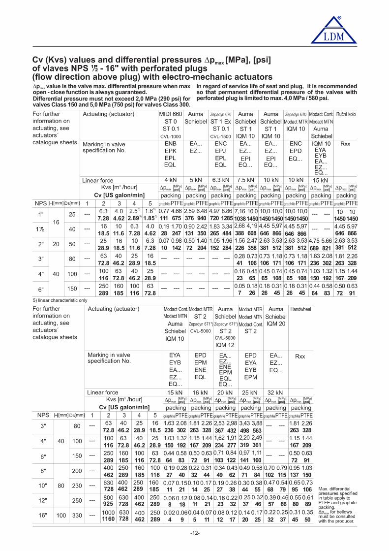
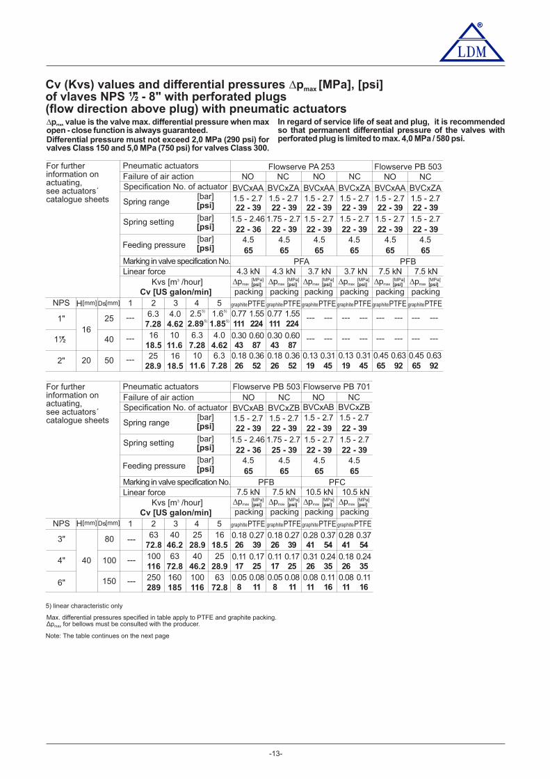
Cv (Kvs) values and differential pressures Δp [MPa], [psi]max
of vlaves NPS ½" - 16" with perforated plugs(flow direction above plug) with electro-mechanic actuatorsΔp value is the valve max. differential pressure when maxmax
open - close function is always guaranteed.Differential pressure must not exceed 2,0 MPa (290 psi) forvalves Class 150 and 5,0 MPa (750 psi) for valves Class 300.
1 2 3 4 5
80
100
150
NPS
6"
3"
4" 40
6372.8
4046.2
252 98.
1618.5
100116
6372.8
4046.2
252 98.
250289
160185
100116
6372.8
2" 20 2528.9
1618.5
1011.6
6.37.28
0.07 0.9810 142
0.50 1.4072 204
1.05 1.96152 284
0.16 0.4523 65
0.45 0.7465 108
0.28 0.7341 106
0.73 1.18106 171
0.05 0.187 26
0.18 0.3126 45
0.45 0.7465 108
0.73 1.18106 171
0.18 0.3126 45
Kvs [m /hour]3
Cv [US galon/min]
50
6.3 kN 7.5 kN4 kN 5 kN 10 kN 10 kN
401½" 1618.5
1011.6
6.37.28
4.04.62
1"16
6.37.28
4.04.62
2.55)
2. 985)
1.65)
1.855)
0.77 4.66111 675
2.59 6.48376 940
4.97 8.86720 1285
0.19 1.7028 247
0.90 2.42131 350
1.83 3.34265 484
1.56 2.47226 358
2.63 3.53381 512
2.63 3.53381 512
25
---
---
---
---
---
---
--- --- --- ------ ---
--- --- --- ------ ---
--- --- --- ------ ---
1.15 1.44167 209
1.81 2.26263 328
0.50 0.6372 91
Kvs [m /hour]3
Cv [US galon/min]
2.63 3.53381 512
15 kN
15 kN
16 kN 20 kN 25 kN 32 kN
4.45 5.97646 866
10 1014501450
0.44 0.5864 83
1.03 1.32150 192
1.63 2.08236
689
1038
388 646 646
302
821
1450 1450
608 866 866
145014501450--- ---
--- ---
5) linear characteristic only
4.75
7,16
2,68 4,45 4,45
5.66
10,0 10,0
4,19 5,97 5,97
10,010,010,0H Ds[mm] [mm]
Actuating (actuator)
Marking in valvespecification No.
Linear force
For furtherinformation onactuating, seeactuators´catalogue sheets
Actuating (actuator)
Marking in valvespecification No.
Linear force
For furtherinformation onactuating, seeactuators´catalogue sheets
EPK EPJ
Zepadyn 670 Auma
ENC EA...
MIDI 660
ENB
ST 1 ExST 0Auma
EA...
Schiebel
EZ...
ST 1IQM 10
EPIEQ...
EPLEQL
EZ...EPLEQL
ST 0.1CVL-1000
SchiebelST 0.1
CVL-1500
EZ...
Auma Zepadyn 670
EA... ENC
Schiebel Modact MTR
IQM 10
EPDEQ...
ST 1IQM 10
EPIEQ...
EYB
EYB
Modact Cont.
Modact Cont.
EYA
EYA
Modact MTN
Modact MTN
Modact MTR
EPD
EA...
EA...
EZ...EQ...
EZ...EQ...
EPMENEEQL
Schiebel
SchiebelIQM 10
Auma
IQM 10
Auma
ST 2
CVL-5000
Zepadyn 671*)
EZ...
Auma Modact MTR
EA... EPD
Schiebel Modact MTN
EYA
Modact Cont.
EYB
ST 2ST 2CVL-5000
IQM 12
EPMEPMEQLEQ...
ENE
Zepadyn 671*)
EZ...EQ...
Auma
IQM 20
EA... Rxx
Rxx
SchiebelHandwheel
Ruční kolo
80
100
150
200
230
250
330
6"
---
---
---
---
3"
4" 40
6372.8
4046.2
252 98.
1618.5
100116
6372.8
4046.2
252 98.
250289
160185
100116
6372.8
250289
160185
100116
8"
10"
12"
16"
80
100
0.49 0.5871 84
0.70 0.79102 115
1.15 1.44167 209
1.81 2.26263 328
0.50 0.6372 91
---
---
---
400462
0.95 1.03137 150
--- ---
--- ---
--- ---
0.19 0.2827 40
0.22 0.3132 44
0.34 0.4349 62
0.44 0.5864 83
0.50 0.6372 91
1.03 1.32150 192
1.15 1.44167 209
1.63 2.08236 367 498
234
103 141
319
302 432 563
277
122 160
361
1.81 2.26263 328
2,53 3,43
1,62
0,71 0,97
2,20
2,98 3,88
1,91
0,84 1,11
2,49
728
925
630
800
11601000
462 289 185400 250 160
728 462 289400630 250
462 289728400630 250
11
8
4
21
18
9
14
11
5
25
21
11
95
80
45
106
89
50
68
57
32
79
66
37
44
37
20
55
46
25
27
23
12
38
32
17
0.07 0.10
0.06 0.08
0.02 0.04
0.15 0.17
0.12 0.14
0.06 0.07
0.47
0.39
0.22
0.54
0.46
0.25
0.26 0.38
0.32
0.17
0.22
0.12
0.19 0.30
0.25
0.14
0.16
0.08
0.65
0.55
0.31
0.73
0.61
0.35
In regard of service life of seat and plug, it is recommendedso that permanent differential pressure of the valves withperforated plug is limited to max. 4,0 MPa / 580 psi.
packing packing packing packingΔpmax [psi]Δpmax [psi]Δpmax [psi]Δpmax [psi]
graphitePTFE graphitePTFE graphitePTFE graphitePTFE
packing packing packing packingΔpmax [psi]Δpmax [psi]Δpmax [psi]Δpmax [psi]
graphitePTFE graphitePTFE graphitePTFE graphitePTFE
1 2 3 4 5NPS H Ds[mm] [mm]
packing packingΔpmax [psi]Δpmax [psi]
graphitePTFE graphitePTFE
packing packing packing packingΔpmax [psi]Δpmax [psi]Δpmax [psi]Δpmax [psi]
graphitePTFE graphitePTFE graphitePTFE graphitePTFE
Max. differentialpressures specifiedin table apply toPTFE and graphitepacking.
for bellowsΔpmax
must be consultedwith the producer.
NO NCFlowserve PA 253
BVCxAA BVCxZA1.5 - 2.7 1.5 - 2.7
NO NCBVCxAA BVCxZA1.5 - 2.7 1.5 - 2.7
NO NCBVCxAA BVCxZA1.5 - 2.7 1.5 - 2.7
Flowserve PB 503
®
-13-
®
Cv (Kvs) values and differential pressures Δp [MPa], [psi]max
of vlaves NPS ½" - 8" with perforated plugs(flow direction above plug) with pneumatic actuators
Kvs [m /hour]3
4.5 4.5 4.5
PFA
4.5
Cv [US galon/min]
22 - 39 22 - 39 22 - 39 22 - 39
22 - 36 22 - 39 22 - 39 22 - 39
65 65 65 65
1 2 3 4 5NPS
4.5 4.5
22 - 39 22 - 39
22 - 39 22 - 39
65 65
1.5 - 2.46 1.75 - 2.7 1.5 - 2.7 1.5 - 2.7 1.5 - 2.7 1.5 - 2.7
4.3 kN 4.3 kN 7.5 kN 7.5 kN3.7 kN 3.7 kN
2" 20 2528.9
1618.5
1011.6
6.37.28
0.18 0.3626 52
0.18 0.3626 52
0.13 0.3119 45
--- --- --- --- --- ---
50
401½" 1618.5
1011.6
6.37.28
4.04.62
1"16
6.37.28
4.04.62
2.55)
2. 985)
1.65)
1.855)
0.77 1.55111 224
0.77 1.55111 224
0.30 0.6043 87
0.30 0.6043 87
--- --- --- ---
0.13 0.3119 45
0.45 0.6365 92
0.45 0.6365 92
--- ---25
---
---
--- --- ---
--- ---
Kvs [m /hour]3
4.5 4.5 4.5
PFC
4.5
Cv [US galon/min]
22 - 39 22 - 39 22 - 39 22 - 39
22 - 36 25 - 39 22 - 39 22 - 39
65 65 65 65
1 2 3 4 5NPS
1.5 - 2.46 1.75 - 2.7 1.5 - 2.7 1.5 - 2.7
7.5 kN 7.5 kN 10.5 kN 10.5 kN
Flowserve PB 503NO NC
BVCxAB BVCxZB1.5 - 2.7 1.5 - 2.7
NO NCFlowserve PB 701
BVCxAB BVCxZB1.5 - 2.7 1.5 - 2.7
80
100
1506"
3"
4" 40
6372.8
4046.2
252 98.
1618.5
100116
6372.8
4046.2
252 98.
250289
160185
100116
6372.8
0.11 0.1717 25
0.1117
0.31 0.2426 35
0.18 0.2426 35
0.18 0.2726 39
0.1826
0.28 0.3741 54
0.28 0.3741 54
0.0811
0.08 0.1111 16
0.08 0.1111 16
---
---
---
0.058
0.058
0.1725
0.2739
0.0811
5) linear characteristic only
PFB
PFB
Note: The table continues on the next page
H Ds[mm] [mm]
H Ds[mm] [mm]
[psi]
Pneumatic actuators
Marking in valve specification No.
Failure of air actionSpecification No. of actuator
Spring range
Spring setting
Feeding pressure
[bar]
[bar]
Linear force
For furtherinformation onactuating,see actuators´catalogue sheets
[bar]
[psi]
[psi]
[psi]
Pneumatic actuators
Marking in valve specification No.
Failure of air actionSpecification No. of actuator
Spring range
Spring setting
Feeding pressure
[bar]
[bar]
Linear force
For furtherinformation onactuating,see actuators´catalogue sheets
[bar]
[psi]
[psi]
Δp value is the valve max. differential pressure when maxmax
open - close function is always guaranteed.Differential pressure must not exceed 2,0 MPa (290 psi) forvalves Class 150 and 5,0 MPa (750 psi) for valves Class 300.
In regard of service life of seat and plug, it is recommendedso that permanent differential pressure of the valves withperforated plug is limited to max. 4,0 MPa / 580 psi.
packing packingΔpmax [psi]Δpmax [psi]
graphitePTFE graphitePTFE
packing packing packing packingΔpmax [psi]Δpmax [psi]Δpmax [psi]Δpmax [psi]
graphitePTFE graphitePTFE graphitePTFE graphitePTFE
packing packingΔpmax [psi]Δpmax [psi]
graphitePTFE
packing packingΔpmax [psi]Δpmax [psi]
graphitePTFE graphitePTFEgraphitePTFE
Max. differential pressures specified in table apply to PTFE and graphite packing.for bellows must be consulted with the producer.Δpmax

®
-14-
®
Kvs [m /hour]3
4.5 5.5 5.5
PFD
4.5
Cv [US galon/min]
22 - 39 22 - 39
22 - 39 22 - 39 29 - 51
29 - 51
29 - 51
29 - 51
65 65 80 80
1 2 3 4 5NPS
3.4 3.419 - 30
19 - 30
19 - 30
19 - 30
49 49
22.5 kN 22.5 kN 39 kN 39 kN30 kN 30 kN
8" 80 400462
250289
160185
100116
0.12 0.1417 20
0.12 0.1417 20
0.16 0.1824 26
2000.16 0.1824 26
0.22 0.2432 35
0.22 0.2432 35
---
NO NCBVCxAD BVCxZD1.5 - 2.7 1.5 - 2.7
NO NCBFSxAD BFSxZD2.0 - 3.5 2.0 - 3.5
Flowserve PO 1502NO NC
Flowserve PO 3002
BEPxAD BEPxZD1.3 - 2.1 1.3 - 2.1
1.5 - 2.7 1.5 - 2.7 2.0 - 3.5 2.0 - 3.5 1.3 - 2.1 1.3 - 2.1
PFE
H Ds[mm] [mm]
[psi]
Pneumatic actuators
Marking in valve specification No.
Failure of air actionSpecification No. of actuator
Spring range
Spring setting
Feeding pressure
[bar]
[bar]
Linear force
For furtherinformation onactuating,see actuators´catalogue sheets
[bar]
[psi]
[psi]
packing packingΔpmax [psi]Δpmax [psi]
graphitePTFE
packing packing packing packingΔpmax [psi]Δpmax [psi]Δpmax [psi]Δpmax [psi]
graphitePTFE graphitePTFE graphitePTFE graphitePTFEgraphitePTFE
Max. differential pressures specified in table apply to PTFE and graphite packing.

Dimensions and weights of valves CV / SV 320 (Ex) CV / SV 330 (Ex)with flanged and welded connection, NPS ½" - 16"
®
-15-
kg kg
6 4
8 4
NPS
1"
1½"
522.047
522.047
kg
9
15
13 42"73
2.87420
M ØD6m1V2 ØD5 m2
[inch] [inch]
H V3 V4
---
V5
M10x1
[mm] [mm]
[inch] [inch] [inch] [inch]
[mm] [mm] [mm] [mm]
[inch] [inch]
[mm] [mm]
[inch] [inch]
[mm] [mm]
[inch] [inch]
[mm] [mm]
[inch] [inch]
[mm] [mm][mm]
[inch] [inch]
[mm] [mm]
160.63 100 336 466
3.937 13.228 18.346
2309.055
200.787
132 330 4605.197 12.992 18.110
26210.314
28 6
37 6
105 7
4"
6"
1054.133
1054.133
1345.275
41
67
160
200 ---
370 ---
520 ---
1130 ---
8"
10"
12"
16"
203
253
296
382
7.992
9.961
11.654
15.039
280
160 ---
---
---
---
---
---
---
---
---
M16x1,5
3"
401.575
164 489 6196.456 19.252 24.370
29411.575
200 492 6227.874 19.370 24.488
33012.992
80
100
3.15
3.937
262
346
395
512
10.314
13.622
15.551
20.157
422
506
555
672
16.614
19.921
21.85
26.457
6.299
1305.118
652.559
1505.905
M20x1,5
RF
26710.5
28311.14
27710.9
28611.25
28911.38
Class 300
2108.25
2078.15
1977.75
2108.25
2108.25
2489.76
2459.64
2359.25
2519.88
2519.88
33233.22
32812.91
568
1057
22.38
41.62
584
1073
22.99
42.24
578
1067
22.75
42.01
610
1108
24.0
43.62
613
1111
24.13
43.74
31812.5
33713.25
34013.38
384
724
15.12
28.5
378
718
14.88
28.27
368
708
14.5
27.88
394
752
15.5
29.62
397
755
15.63
29.72
489
791
19.25
31.14
483
785
19.01
30.91
473
775
18.62
30.5
508
819
20.0
32.25
511
822
20.12
32.36
28611.25
L1
RTJ
LFFSFFLGFSGF
Class 600 Class150 - 600
L2
RF RTJ
LFFSFFLGFSGF
BTW
28311.14
2078.15
2489.76
607
1105
60.72
43.5
33413.15
391
749
15.39
29.49
505
816
19.88
32.13
2519.88
2108.25
610
752
819
1108
24.0
29.62
32.25
43.62
50820.0
39415.5
33713.25
5 447
1.857½"
90 328 4583.543 12.913 18.031
2208.661
2017.91
2007.87
1907.5
2038.0
2027.95
2007.87
2038.0
#mV#V2
#V3
540
680
1380
NPS
1"
1½"
2"
[inch]
[mm]
[inch]
[mm]
[inch]
[mm]
[inch]
[mm]
[inch]
[mm]
½"95
3.75
66.72.62
1656.5
1275.0
4"
10"
6"
12"
8"
16"
3"
92.13.62
19.1
12
1616
20
nØD1 d aØD2 ØD3
[inch]
[mm]
b
34.91.38
15.95/8"
1254.88
88.93.5
50.82.0
19.1
1556.12
114.34.5
732.88
22.37/8"
2108.25
168.36.62
380
650
15
25.59
330.2
571.5
13.0
22.5
269.9
469.9
10.62
18.5
25.41"
1275.0
22.37/8"
255
445
10
17.52
200
387.4
7.88
15.25
157.2
323.8
6,19
12.75
22.3
28.6 34.9
31.8 34.9
34.9 41.3
7/8"
1 ⅛" 1 ⅜"
1 ¼" 1 ⅜"
1 ⅜" 1 ⅝"
320
520
12.5
20.47
269.9
450.8
10.62
17.75
215.9
381
8,5
15
22.37/8"
39.7
55.6
1.56
2.19
35
49.3
1.38
1.94
8
4
30.2
46.1
1.19
1.82
271.06
20.70.81
19.10.75
15.90.62
12.70.5
20.06
[inch]
[mm]
[inch]
[mm]
[inch]
[mm]
[inch]
[mm]
[inch]
[mm]
953.75
66.72.62
1656.5
1275.0
92.13.62
19.1¾"
12
20
nØD1 d aØD2 ØD3
[inch]
[mm]
b
34,91.38
15.95/8"
1254.88
88.93.5
50,82.0
19.1¾"¾"
¾"
1556.12
114.34.5
732.88
22.37/8"
2108.25
168.36.62
420
685
16.5
26.97
349.2
603.2
13.75
23.75
269.9
469.9
10.62
18.5
31.81 ¼"
1275.0
22.37/8"
275
510
10.75
20.08
215.9
431.8
8.5
17
157.2
323.8
6.19
12.75
25.41"
355
560
14.0
22.05
292.1
489
11.5
19.25
215.9
381
8.5
15
28.61 1/8"
55.6
76.2
2.19
3
47.7
66.7
1.88
2.63
8
4
38.1
63.5
1.5
2.5
31.81.25
25.41.0
22.30.88
17.50.69
14.30.56
70.25
RF Class 300 RF Class 600
[inch]
[mm]
[inch]
[mm]
[inch]
[mm]
5.540.219
7.140.281
82.553.25
7.920.312
ØD7
34.141.344
R11
6.350.25
8.740.344
50.82.0
R16
6.350.25
68.272.688
R23
7.920.312
269.9
469.9
10.625
18.5
7.92
7.92
0.312
0.312
11.91
11.91
0.469
0.469
R49
R65
117.484.625
R30
7.92
7.92
0.312
0.312
149.23
323.85
5.875
12.75
R37
R53
7.92
7.92
0.312
0.312
211.12
381
8.312
15
R45
R57
e fRTJ Class 300 a 600
R208.740.344
11.91
11.91
0.469
0.469
11.91
11.91
0.469
0.469
11.910.469
11.910.469
GrooveNumber

®
-16-
a ab
e
eb
L2
L1
V5
V3
V2
V4
H
t
f
f
D6
D5
D4
D7 D7
D3
D2
D1
NP
S
n x
d
V5
M
t
D4
D3
D2
D1
NP
S
L2
L1
n x
d
D6
V3
V4
V2
H
t T1,6
37,5°
DD4 d4
62 67 4360.32.44 2.638 1.6932.375
3.90.154
5.50.218
35
22
40
30
23
13
33.4
21.3
1.378
0.866
1.575
1.181
0.906
0.512
1.315
0.839
3.4
2.8
0.133
0.109
4.6
3.9
0.179
0.154
50 57 3548.31.969 2.244 1.3781.66
3.70.14
5.10.191
91 100 7288.93.583 3.937 2.8353.5
5.50.216
223
278
329
413
228
278
329
426
178
229
281
345
219.1
273.0
323.9
406.4
8.78
10.945
12.953
16.26
8.976
10.945
12.953
16.772
7.008
9.016
11.063
13.583
8.625
10.748
12.752
16.0
8.2
9.3
10.3
12.7
0.322
0.366
0.406
0.5
12.7
15.1
17.5
21.4
15.1
18.3
21.4
26.2
0.5
0.594
0.689
0.843
0.594
0.72
0.843
1.031
7.60.3
117 128 92114.34.606 5.039 3.6224.5
6.00,237
8.60.337
172 188 136168.36.772 7.402 5.3546.625
7.10,28
11.00.432
Dimensions of weld ends for pipesacc. to ASME B36.10M
1"
½"
1½"
2"
4"
6"
8"
10"
12"
16"
3"
[mm][inch]
NPS D
tT
D4D4 max d4 minSch.
No. 40
Sch.
No. 80
Sch.
No. 100
NPS ½" - 6" NPS 8"- 16"
---
---
---
---
---
---
---
t [ ]- wall thickness of weld ends: t = D - (D - 2 * t ) / 24 T
Dimensions of weld ends for pipesacc. to ASME B16.11
[mm][inch]
NPS
1"
1½"
2"
½"15 12
0.59 0.47
22 220.87 0.87
52 432.05 1.69
61,4 61,42.42 2.42
762.99
843.31
286 28616 16
h hØD5 ØD5ØD6 ØD6ØD7 ØD7L3 L3
33 351.3 1.38
206 2069,5 9,58.11 8.110.37 0.37
26 211.02 0.83
34,1 34,11.34 1.34
47 511.85 2.01
210 21012,5 12,5
41 341.61 1.34
49 491.93 1.93
62 672.44 2.64
251 25112,5 12,59.88 9.880.49 0.49
8.27 8.270.49 0.49
11.26 11.260.63 0.63
SW Class 150 a 300 SW Class 600h
D5
D6
D7
L3

®
-17-
Pressure balanced control valvesNPS 1"- 16" Class 150, 300 and 600
CV 3x2
Technical dataCV 322 (Ex) CV 332 (Ex)
Two-way, single-seated, control valve(shut-off)
Cast steelA351 CF8M
1.4571 / 17 348.41.4027 / 42 2906.5
1.4581 / 42 2941.4
Acc. to ASME B16.5-2013
1,6 až m /houd (1,85 to US galon/min)1600 18503
Class III. dle ANSI/FCI 70-2-2006 (<0.1% Cv) por control valves with metal-metal seat sealing
Rate C dle ISO 5208:2008
DRSpack (PTFE) t = 260 °C (500 °F), t = 550 °C (1020 °F),®max maxExp. graphite Bellows (DN 15-150) t = 550 °Cmax
Stainless steelA216 WCC, A217 WC9
1.4028 / 17 023.6
1.4571 / 17 348.41.4027 / 42 2906.5
-10 to 550 °C (14 to 1020 °F)
V-ported, contoured, perforatedLinear, equal-percentage, LDMspline , parabolic, on - off� �
50 : 1
NPS 1" to 16"
1.4571 / 17 348.41.4021 / 17 022.6
1.4021 / 17 027.61.4581 / 42 2941.4
Class 300 and 600 (Class 150, 300 and 600 )weld ended
DescriptionControl valves V 2 (Ex) V (Ex) (further only VC 3 2 and C 332 C3 2 with pressure balanced plugx (Ex) are single-seated valvesdesigned for regulation of process medium flow. Due to pressurebalanced plug, the valves are suitable for regulation at highdifferential pressures . Flowwith low-linear-force actuatorscharacteristics, Kvs values and leakage ratesand Cvcorrespond to international standards.Valves V / V x (Ex) are equipped with hand wheel or areC S 3 2especially designed for electro-mechanic actuators of thefollowing producers: ZPA Nová Paka, Regada, ZPA Pečky,Schiebel, Auma, Rotork or for pneumatic actuators SPA Prahaand Flowserve.
ApplicationThe valves series CV 3x2 are designed for applications inheating, ventilation, power generation and chemicalprocessing industries. The valves CV 3x2 Ex meet therequirements II 1/2G IIB TX acc.to ČSN-EN 13463-1 (6/2009)and ČSN EN 1127-1 (5/2008), and in connection with suitableactuators, they are also designed for applications in gas andchemical industries. Valve body can be optionally made of caststeel or stainless steel.The materials selected correspond to recommendationsstipulated by ČSN-EN 1 -1ASME B16.34-2013 or 2516(1/200 ) The maximal permissible operating pressures in6 .behaviour with types of material and temperature are specifiedin the table on page of this catalogue.86
Process mediaValves series CV 3x2 are designed for regulation of flow andpressure of liquids, gases and vapours without abrasive particlese.g. water, steam, air and other media compatible with material ofthe valve body and inner parts. The valves series CV 3x2 Ex arealso designed for control of the flow and pressure of technical andfuel gases and inflammable liquids. To ensure a reliableregulation, the producer recomends to pipe a strainer in front ofthe valve into pipeline or ensure in any other way that processmedium does not contain abrasive particles or impurities.
InstallationThe valve be piped the way so that the direction of mediummustflow will coincide with the arrows on the body.valve Reverse flowdirection is not permissible.The valve can be installed in any position except position whenthe actuator is under the valve body. When medium temperatureexceeds 150°C (300°F), it is necessary to protect the actuatoragainst glowing heat from the pipeline e.g. by the means ofproper insulating of the pipeline and valve or by tilting the valveaway from the heat radiation.Detailed informations are given in the instruction for installation and
Face to face dimensions
Packing
Kvs (Cv) valueLeakage rate
Leakage rate for Ex version
Connection flanges
Rangeability r
SeriesType of valveNominal size rangeNominal pressureBody material
Seat material :DIN W.Nr./+ČSNPlug material :DIN W.Nr./+ČSN
Operating temperature range
Flange faces RF (Raised Face), RTJ (Ring Joint Face), LFF (Large Female Face), SFF (Small Female Face),LGF (Large Groove Face), SGF (Small Groove Face), for NPS 10", 12" and 16" weld ended execution only
acc. to ISA-75.08.01-2002 /R2007) for flange connection, acc. to ISA-75.08.05-2002 (R2007) for weld ended execution
Flow characteristicType of plug
NPS /2" 2"1 -NPS 3" - 16"
NPS 3" - 6"NPS 8" - 16"
NPS /2" 2"1 -
Class IV. acc. to ČSN EN 1349 (7/2010) (<0.01% Cv) for control valves with metal-PTFE seat sealing

®
-18-
Cv (Kvs) values and differential pressures Δp [MPa], [psi]max
for pressure-balanced valves NPS 1" - 16" with electromechanic actuators
101450
101450
101450
101450
101450
101450
10
10
1450
1450
101450
101450
10
10
1450
1450
101450
101450
packingpacking packing
1 2 3 4 5
80
200
230
250
330
100
150
NPS
6"
grafit PTFE grafit PTFE grafit PTFE
3"
4" 40
100116
160185
8"
10"
12"
16"
80
100
---
---
---
---
---
---
---
---
---
---
---
--- --- ---
---
Kvs [m /hour]3
Cv [US galon/min]
Δpmax [psi][Mpa] Δpmax [psi]
[Mpa] Δpmax [psi][Mpa]
360416
570659
6372.8
4046.2
252 98.
1618.5
100116
6372.8
4046.2
252 98.
250289
160185
100116
6372.8
250289
160185
100116
400462
15 kN 16 kN
---
---
---
--- ---
--- ---
--- ---
10
10
10
10
1450
1450
1450
1450
10
10
10
10
1450
1450
1450
1450
101450
101450
10
10101450
14501450
101450
101450
10
10101450
14501450
--- ---
--- ---
---
---
---
---
101450
101014501450
101450
packing
grafit PTFE
Δpmax [psi][Mpa]
Hand wheel
Rxx
101450
101450
101014501450
101450
101450
101014501450
101014501450
101014501450
101014501450
101450
101450
EYB
Auma Modact MTR
EPD
Modact Cont.
EYA
15 kN
SchiebelModact MTN
EA...
ST 2
EPM
Zepadyn 671*)
ENEEZ... EZ...
Auma Modact MTR
EA... EPD
20 kN 25 kN
Schiebel Modact MTN
EYA
Zepadyn 671*) Modact Cont.
EYB
ST 2
EPM
ENE
grafit PTFE grafit PTFE
packing ucpávkaΔpmax Δpmax
728
925
630
800
11601000
462 289 185400 250 160
728 462 289400630 250
462 289728400630 250
925
1160
800
1000
18501600
H Ds[mm] [mm]
Actuating (actuator)
Marking in valvespecification No.
Linear force
For furtherinformation onactuating, seeactuators´catalogue sheets
Max. differential pressures specified in table apply to PTFE and packing.graphiteCv (Kvs)Perforated plug available only with values in shadowed frames with the following restrictions:
- perforated plug with Kvs value acc. to column No. 2 available with linear or parabolic characteristic only
1 2 3 4 5
50
80
100
150
NPS
6"
3"
4" 40
4046.2
100116
160185
2"
252 98.
101450
101450
101450
--- ------ --- ---
---
Kvs [m /hour]3
Cv [US galon/min]
40
1"16
1011.6
---25
1½"
20
360416
6372.8
4046.2
252 98.
1618.5
100116
6372.8
4046.2
252 98.
250289
160185
100116
6372.8
252 98.
1618.5
1011.6
6.35)
7.285)
1618.5
1011.6
6.35)
7.285)
4.05)
4.625)
6.35)
7.285)
4.05)
4.625)
2.55)
2. 985)
1.65)
1.855)
ENBEQL
2 kN
MIDI 660CVL-500
ST 0 CVL-1000
CVL-1500
EPK EQL
EQL
2.5 kN 4 kN
EZ...
Auma Zepadyn 670
EA... ENC
5 kN 6.3 kN
Schiebel ST 1 Ex
EPJ
ST 0.1
EPL
ST 1IQM 10
ST 1IQM 10
EPIEQ...
EPIEQ...
7.5 kN 10 kN
---
---
---
---
---
---
---
---
101450
101450
101450
101450
101450
101450
101450
101450
101450
101450
101450
101450
101450
101450
101450
101450
101450
101450
101450
101450
101450
101450
101450
101450
101450
101450
101450
101450
101450
101450
101450
101450
101450
101450
101450
101450
101450
101450
101450
101450
101450
10 101450 1450
10 101450 1450
10 101450 1450
10 101450 1450
10 101450 1450
10 101450 1450
101450
101450
101450
---
---
--- ---
--- ---
--- ---
--- --- 101450
101450
101450
Ruční kolo
Rxx
101450
101450
101450
101450
101450
101450
101450
101450
101450
H Ds[mm] [mm]
Actuating (actuator)
Marking in valvespecification No.
Linear force
For furtherinformation onactuating, seeactuators´catalogue sheets
5) linear characteristic only
Δp value is the valve max. differential pressure when maxmax
open - close function is always guaranteed.Differential pressure must not exceed 2,0 MPa (290 psi) forvalves Class 150 and 5,0 MPa (750 psi) for valves Class 300.
In regard of service life of seat and plug, it is recommendedso that permanent differential pressure would not exceed 1.6MPa / 232 psi. Otherwise it is suitable to use perforated plug( p up to 4,0 MPa / 580 psi) or sealing surfaces of seat andΔplug with a hard metal overlay ( p up to 2,5 MPa / 363 psi).Δ
packing packingΔpmax [psi]Δpmax [psi]
graphitePTFE
packing packing packing packingΔpmax [psi]Δpmax [psi]Δpmax [psi]Δpmax [psi]
graphitePTFE graphitePTFE graphitePTFE graphitePTFEgraphitePTFE
packing packingΔpmax [psi]Δpmax [psi]
graphitePTFE graphitePTFE

®
-19-
Cv (Kvs) values and differential pressures Δp [MPa], [psi]max
for pressure-balanced valves NPS 1" - 16" with pneumatic actuators
Kvs [m /hod]3
4.5 4.5
Cv [US galon/min]
22 - 39 22 - 39
22 - 36 25 - 39
65 65
1 2 3 4 5NPS
4.3 kN 4.3 kN
801½" 1618,5
1011.6
6.35)
7.285)
4.05)
4.625)
1"16
6.35)
7.285)
4.05)
4.625)
2.55)
2. 985)
1.65)
1.855)50
BVCxAA1.5 - 2.7
NO NCBVCxZA1.5 - 2.7
Flowserve PA 253
1.5 - 2.46 1.75 - 2.7
101450
101450
101450
101450
101450
101450
101450
101450
4.5
PFA
4.5
22 - 39 22 - 39
22 - 39 22 - 39
65 65
3.7 kN 3.7 kN
NO NCBVCxAA BVCxZA1.5 - 2.7 1.5 - 2.7
1.5 - 2.7 1.5 - 2.7
50 4046.2
2" 20 252 98.
1618.5
1011.6
6.35)
7.285)
101450
101450
101450
101450
252 98.
1011.6
---
---
---
---
---
---
---
---
------ ------
4.5 4.5
22 - 39 22 - 39
22 - 39 22 - 39
65 65
7.5 kN 7.5 kN
BVCxAA1.5 - 2.7
NO NCBVCxZA1.5 - 2.7
Flowserve PB 503
1.5 - 2.7 1.5 - 2.7
PFB
50 4046.2
2" 20 252 98.
1618.5
1011.6
6.35)
7.285)
101450
101450
101450
101450
Kvs [m /hour]3
4.5 4.5 4.5
PFC
4.5
Cv [US galon/min]
22 - 39 22 - 39 22 - 39 22 - 39
22 - 39 22 - 39 22 - 39 22 - 39
65 65 65 65
1 2 3 4 5NPS
1.5 - 2.7 1.5 - 2.7 1.5 - 2.7 1.5 - 2.7
7.5 kN 7.5 kN 10.5 kN 10.5 kN
NO NCBVCxAB BVCxZB1.5 - 2.7 1.5 - 2.7
NO NCFlowserve PB 701
BVCxAB BVCxZB1.5 - 2.7 1.5 - 2.7
80
100
1506"
3"
4" 40
6372.8
4046.2
252 98.
1618.5
100116
6372.8
4046.2
252 98.
250289
160185
100116
6372.8
100116
160185
360416
10
10
1450
1450
10
10
1450
1450
10
10
1450
1450
10
10
1450
1450
101450
101450
101450
101450
10
10
1450
1450
10
10
1450
1450
10
10
1450
1450
10
10
1450
1450
101450
101450
101450
101450
---
---
---
---
---
---
---
---
---
---
---
---
---
---
---
---
------ ------
H Ds[mm] [mm]
H Ds[mm] [mm]
[psi]
Pneumatic actuators
Marking in valve specification No.
Failure of air actionSpecification No. of actuator
Spring range
Spring setting
Feeding pressure
[bar]
[bar]
Linear force
For furtherinformation onactuating,see actuators´catalogue sheets
[bar]
[psi]
[psi]
[psi]
Pneumatic actuators
Marking in valve specification No.
Failure of air actionSpecification No. of actuator
Spring range
Spring setting
Feeding pressure
[bar]
[bar]
Linear force
For furtherinformation onactuating,see actuators´catalogue sheets
[bar]
[psi]
[psi]
5) linear characteristic only
Max. differential pressures specified in table apply to PTFE and packing.graphiteCv ( )Perforated plug available only with Kvs values in shadowed frames with the following restrictions:
- perforated plug with Kvs value acc. to column No. 2 available with linear or parabolic characteristic only
Note: The table continues on the next page
Δp value is the valve max. differential pressure when maxmax
open - close function is always guaranteed.Differential pressure must not exceed 2,0 MPa (290 psi) forvalves Class 150 and 5,0 MPa (750 psi) for valves Class 300.
In regard of service life of seat and plug, it is recommendedso that permanent differential pressure would not exceed 1.6MPa / 232 psi. Otherwise it is suitable to use perforated plug( p up to 4,0 MPa / 580 psi) or sealing surfaces of seat andΔplug with a hard metal overlay ( p up to 2,5 MPa / 363 psi).Δ
packing packing packing packingΔpmax [psi]Δpmax [psi]Δpmax [psi]Δpmax [psi]
graphitePTFE graphitePTFE graphitePTFE graphitePTFE
packing packingΔpmax [psi]Δpmax [psi]
graphitePTFE
packing packing packing packingΔpmax [psi]Δpmax [psi]Δpmax [psi]Δpmax [psi]
graphitePTFE graphitePTFE graphitePTFE graphitePTFEgraphitePTFE

®
-20-
Kvs [m /hour]3
Cv [US galon/min]
1 2 3 4 5NPS
4.5 4.5
PFD
22 - 39 22 - 39
22 - 39 22 - 39
65 65
1.5 - 2.7 1.5 - 2.7
22.5 kN 22.5 kN
NO NCFlowserve PO 1502
BVCxAD BVCxZD1.5 - 2.7 1.5 - 2.7
8" 80 400462
250289
160185
100116
200 570659
10 10
10
10
10
1450 1450
1450
1450
1450
10 10
10
10
10
1450 1450
1450
1450
1450
10 10
10
10
10
1450 1450
1450
1450
1450
10 10
10
10
10
1450 1450
1450
1450
1450------ ------
---
---
---
---
---
---
---
---
---
---
---
---
---
---
---
---
---
---
---
---
---
---
---
---
NO NONC NCFlowserve PO 1502 Flowserve PO 1502
BVCxAD BJIOAEBVCxZD DJIOZE1.8 - 3.8 1.8 - 3.8
1.8 - 3.8
5.6
30 kN 27 kNPFD PFD
1.8 - 3.8
5.6
30 kN 27 kN
230
250
330
10"
12"
16"
80
100
728
925
630
800
11601000
462 289 185400 250 160
728 462 289400630 250
462 289728400630 250
925
1160
800
1000
18501600
26 - 55 26 - 55
26 - 55 26 - 5529 - 51
29 - 51
29 - 51
29 - 512.0 - 3.5 2.0 - 3.5
2.0 - 3.5 2.0 - 3.5
5.5 5.580 80 81 81
H Ds[mm] [mm]
[psi]
Pneumatic actuators
Marking in valve specification No.
Failure of air actionSpecification No. of actuator
Spring range
Spring setting
Feeding pressure
[bar]
[bar]
Linear force
For furtherinformation onactuating,see actuators´catalogue sheets
[bar]
[psi]
[psi]
Max. differential pressures specified in table apply to PTFE and packing.graphiteCv ( )Perforated plug available only with Kvs values in shadowed frames with the following restrictions:
- perforated plug with Kvs value acc. to column No. 2 available with linear or parabolic characteristic only
packing packingΔpmax [psi]Δpmax [psi]
graphitePTFE
packing packing packing packingΔpmax [psi]Δpmax [psi]Δpmax [psi]Δpmax [psi]
graphitePTFE graphitePTFE graphitePTFE graphitePTFEgraphitePTFE

Dimensions and weights of valves CV 322 (Ex) CV 332 (Ex)with flanged and welded connection, NPS 1" - 16"
®
-21-
kg
6
8
NPS
1"
1½"
522.047
522.047
kg
9.5
16
132"73
2.87421
M ØD6 m1V2 ØD5 m2
[inch] [inch]
H V3 V4
---
V5
M10x1
[ ]mm [ ]mm
[inch] [inch]
[ ]mm [mm]
[inch] [inch]
[ ]mm [mm]
[inch] [inch]
[ ]mm [mm]
[inch] [inch]
[ ]mm [mm]
[inch] [inch]
[ ]mm [mm][ ]mm
[inch] [inch]
[ ]mm [mm]
160.63
1003.937
2309.055
200.787
1325.197
26210.314
30
40
115
4"
6"
1054.133
1054.133
1345.275
45
72
170
M16x1,5
3"
401.575
1646.456
29411.575
2007.874
33012.992
1305.118
652.559
RF
26710.5
28311.14
27710.9
28611.25
28911.38
2108.25
2078.15
1977.75
2108.25
2108.25
2489.76
2459.64
2359.25
2519.88
2519.88
33233.22
32812.91
31812.5
33713.25
34013.38
38415.12
37814.88
36814.5
39415.5
39715.63
48919.25
48319.01
47318.62
50820.0
51120.12
28611.25
L1
RTJ
LFFSFFLGFSGF
L2
RF RTJ
LFFSFFLGFSGF
BTW
28311.14
2078.15
2489.76
33413.15
39115.39
50519.88
2519.88
2108.25
50820.0
39415.5
33713.25
210
400
550
1200
8"
10"
12"
16"
203
253
296
382
7.992
9.961
11.654
15.039
290
160 ---
80
100
3.15
3.937
262
346
395
512
10.314
13.622
15.551
20.157
422
506
555
672
16.614
19.921
21.85
26.457
6.299150
5.905
M20x1,5
56822.38
58422.99
57822.75
61024.0
61324.13
60760.72
610
752
819
1108
24.0
29.62
32.25
43.62
kg
4
4
4
6
6
7
---
---
---
---
#mV
[inch] [inch]
[mm] [mm]
336 46613.228 18.346
330 46012.992 18.110
---
---
---
---
---
---
---
---
489 61919.252 24.370
492 62219.370 24.488
#V2#V3
Class 300 Class 600Class
150300600
105741.62
107342.24
106742.01
110843.62
111143.74
72428.5
71828.27
70827.88
75229.62
75529.72
79131.14
78530.91
77530.5
81932.25
82232.36
110543.5
74929.49
81632.13
540
680
1380
NPS
1"
1½"
2"
[inch]
[mm]
[inch]
[mm]
[inch]
[mm]
[inch]
[mm]
[inch]
[mm]
1656.5
1275.0
4"
6"
8"
3"
92.13.62
19.1
12
nØD1 d aØD2 ØD3
[inch]
[mm]
b
1254.88
88.93.5
50.82.0
19.1
1556.12
114.34.5
732.88
22.37/8"
2108.25
168.36.62
38015
330.213.0
269.910.62
25.41"
1275.0
22.37/8"
25510
2007.88
157.26,19
22.37/8"
32012.5
269.910.62
215.98,5
22.37/8"
39.71.56
351.38
8
4
30.21.19
271.06
20.70.81
19.10.75
15.90.62
20.06
[inch]
[mm]
[inch]
[mm]
[inch]
[mm]
[inch]
[mm]
[inch]
[mm]
1656.5
1275.0
92.13.62
19.1¾"
12
nØD1 d aØD2 ØD3
[inch]
[mm]
b
1254.88
88.93.5
50,82.0
19.1¾"¾"
¾"
1556.12
114.34.5
732.88
22.37/8"
2108.25
168.36.62
42016.5
349.213.75
269.910.62
31.81 ¼"
1275.0
22.37/8"
27510.75
215.98.5
157.26.19
25.41"
35514.0
292.111.5
215.98.5
28.61 1/8"
55.62.19
47.71.88
8
4
38.11.5
31.81.25
25.41.0
22.30.88
17.50.69
70.25
RF Class 300 RF Class 600
[inch]
[mm]
[inch]
[mm]
[inch]
[mm]
82.553.25
7.920.312
ØD7
6.350.25
8.740.344
50.82.0
R16
6.350.25
68.272.688
R23
7.920.312
269.910.625
7.920.312
11.910.469
R49
117.484.625
R30
7.920.312
149.235.875
R37
7.920.312
211.128.312
R45
e fRTJ Class 300 a 600
R208.740.344
11.910.469
11.910.469
11.910.469
11.910.469
GrooveNumber
10"
12"
16"
1616
20650
25.59571.522.5
469.918.5
44517.52
387.415.25
323.812.75
28.6 34.9
31.8 34.9
34.9 41.3
1 ⅛" 1 ⅜"
1 ¼" 1 ⅜"
1 ⅜" 1 ⅝"
52020.47
450.817.75
38115
55.62.19
49.31.94
46.11.82
20685
26.97603.223.75
469.918.5
51020.08
431.817
323.812.75
56022.05
48919.25
38115
76.23
66.72.63
63.52.5
469.918.5
7.920.312
11.910.469
R65
7.920.312
323.8512.75
R53
7.920.312
38115
R5711.910.469
11.910.469
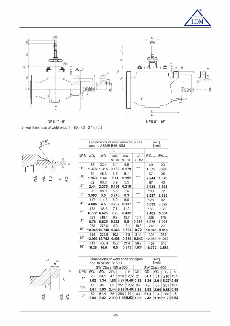
®
-22-
a ab
e
eb
L2
L1
V5
V3
V2
V4
H
t
f
f
D6
D5
D4
D7 D7
D3
D2
D1
NP
S
n x
d
V5
M
t
D4
D3
D2
D1
NP
S
L2
L1
n x
d
D6
V3
V4
V2
H
t T1,6
37,5°
DD4 d4
NPS 1" - 6" NPS 8" - 16"
62 67 4360.32.44 2.638 1.6932.375
3.90.154
5.50.218
35 40 2333.41.378 1.575 0.9061.315
3.40.133
4.60.179
50 57 3548.31.969 2.244 1.3781.66
3.70.14
5.10.191
91 100 7288.93.583 3.937 2.8353.5
5.50.216
223 228 178219.18.78 8.976 7.0088.625
8.20.322
12.7 15.10.5 0.594
7.60.3
117 128 92114.34.606 5.039 3.6224.5
6.00,237
8.60.337
172 188 136168.36.772 7.402 5.3546.625
7.10,28
11.00.432
1"
1½"
2"
4"
6"
8"
3"
NPS D
tT
D4D4 max d4 minSch.
No. 40
Sch.
No. 80
Sch.
No. 100
---
---
---
---
---
---
278
329
413
278
329
426
229
281
345
273.0
323.9
406.4
10.945
12.953
16.26
10.945
12.953
16.772
9.016
11.063
13.583
10.748
12.752
16.0
9.3
10.3
12.7
0.366
0.406
0.5
15.1
17.5
21.4
18.3
21.4
26.2
0.594
0.689
0.843
0.72
0.843
1.031
10"
12"
16"
t [ ]- wall thickness of weld ends: t = D - (D - 2 * t ) / 24 T
Dimensions of weld ends for pipesacc. to ASME B36.10M
[mm][inch]
Dimensions of weld ends for pipesacc. to ASME B16.11
[mm][inch]
NPS
1"
1½"
2"52 43
2.05 1.69
61,4 61,42.42 2.42
762.99
843.31
286 28616 16
h hØD5 ØD5ØD6 ØD6ØD7 ØD7L3 L3
26 211.02 0.83
34,1 34,11.34 1.34
47 511.85 2.01
210 21012,5 12,5
41 341.61 1.34
49 491.93 1.93
62 672.44 2.64
251 25112,5 12,59.88 9.880.49 0.49
8.27 8.270.49 0.49
11.26 11.260.63 0.63
SW Class 150 a 300 SW Class 600h
D5
D6
D7
L3

®
-23-
Valve complete specification No. for ordering CV/SV 3x0 (Ex), CV 3x2 (Ex)
For marking of actuators in specification code, refer to tableon page No. 80 of this catalogue
Ordering example of flanged execution:CV320 ENC 2135 L1 300/400-080
Ordering example of weld ends execution:CV320 ENC 7135 L1 300/400-080, weld ends size Ø 88,9 x 5,5
XXX-XXX/XX-X XX X X XX X XX X XXXControl valve1. Valve CVShut-off valve SV
2. Series 3 2Valves made of cast steel3 3Valves made of stainless steel
Straight-through2Straight-through with pressure balanced plug
Electric actuator3. Actuating
4. Connecting
Cast steel 1.06195. Body materialCrMo steel 1.7357Stainless steel 1.4581Other material on request
1789
(Operating temperature rangesare specified in parentheses
6. Seat sealing
Exp. graphite7. Packing
5
8. Flow characteristic LR
UPDQZ
Column No. acc. to Kvs value table9. Kvs X10. Nominal pressure PN
11. Max. operating temp.°C DRSpack (PTFE)Exp. graphite
Exp. graphite
260300315
DN12. Nominal size DN XXX
P X X
DRSpack (PTFE) 3
o
S
®
®
XX
13. Execution NormalNon - explosive
Pneumatic actuator
Ex
E X X
0
Hand wheel R X X
Exp. graphite 550
®
Parabolic - perforated plug
LinearEqual-percentage
On-offLDMspline
ParabolicLinear - perforated plugEqual-percentage - perforated plug
Exp. graphiteExp. graphite 400
500
Flange RF (Raised Face)Flange RTJ (Ring Joint Face)
12
FlangeLFF (Large Female Face) 3Flange SFF (Small Female Face)Flange LGF (Large Groove Face)
45
Flange SGF (Small Groove Face)
Weld ends SW (Socket Welding)
6
8
Exp. graphite 425
87
9Bellows safety packing PTFE 1)
Bellows safety packing Grafit 1)
Bellows 1)
1 )NPS 1/2" to 6" only
½"1"
1½"2"3"4"
6"8"
015025040050080100
150200
DNDN NPSNPS
500570600750800930
1020
260300315400425500550
Temp.
°F°C
10"12"16"
250300400
Weld ends BW (Butt Welding) 7
(-10 to 425°C); (14 to 800°F)
(-10 to 550°C); (14 to 1020°F)
(-10 to 550°C); (14 to 1020°F)
Class 600 600Class 300Class 150 (welded ends only)
300150
2)NPS 1" - 6" ; t = 260°Cmax
3)NPS 3" - 16"NPS 1 a 1/2" - 16"
4)
Metal - metal
Balanced by graphite, metal-metal 3)
Balanced by graphite, hard metal overlay 4)
Hard metal overlay on sealilng surfacesof RV 3x2, a plug with metal sealing cuff
Soft sealing (metal - PTFE)2)
Hard metal overlay on sealilng surfaces
12357
8
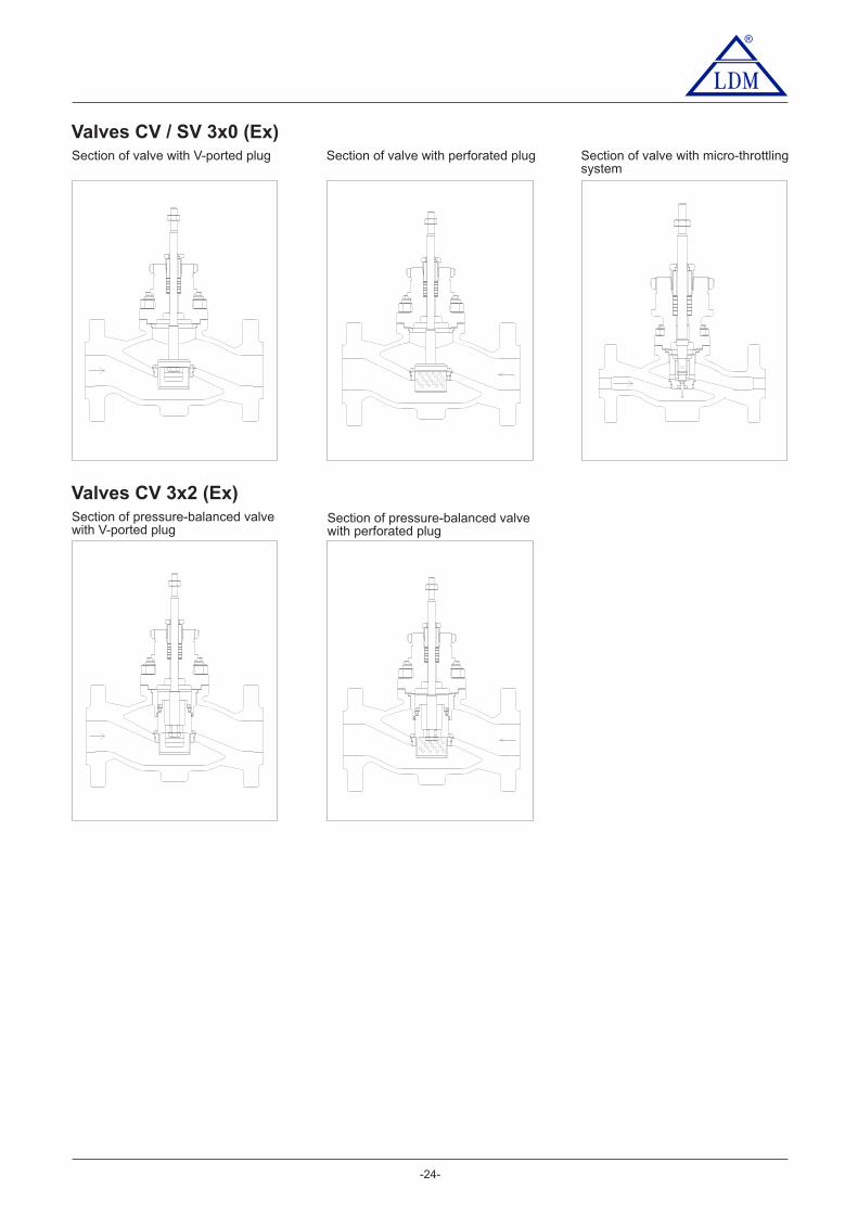
®
-24-
Valves CV / SV 3x0 (Ex)Section of valve with V-ported plug Section of valve with perforated plug Section of valve with micro-throttling
system
Valves CV 3x2 (Ex)Section of pressure-balanced valvewith V-ported plug
Section of pressure-balanced valvewith perforated plug

Note: Specifications and technical data are for information only.
Dimensions of actuator MIDI 660
®
- -25
Electric actuator MIDI 660ZPA Nová Paka
ENB
Technical data
ENB230 V or 24 V50 Hzmax. 193 - position control, 0 - 10 V, 0(4) - 20 mA2000, 4000 N16, 2 mm0IP 65Acc. to used valve-25 to 55 C10 - 100 % with condensation3,5 kg
MIDI 660 XXX
o
Marking in valve specification No.VoltageFrequencyPower consumptionControlNominal forceTravelEnclosureProcess medium max. temperatureAmbient temperatrure rangeAmbient humidity rangeWeight
Type
POSITION
POSITION
Detailed technical informations can be found in producer's data sheet or on the webside www.zpanp.cz

-26-
®
Electric actuator Zepadyn 670ZPA Nová Paka
ENC
Technical data
Marking in valve specification No.VoltageFrequencyPower consumptionControlNominal forceTravelEnclosureProcess medium max. temperatureAmbient temperature rangeAmbient humidity rangeWeight
ENC230 V or 24 V50 Hz38,5 VA, heat resistance 15 W3 - position control, 0 - 10 V, 0(4) - 20 mA6300 and 10000 N16, 2 , 40 mm0IP 65Acc. to used valve-25 to 55 C10 - 100 % with condensation11 kg
Type Zepadyn 670 XXX
o
Dimensions of actuator Zepadyn 670
POSITION
POSITION
Note: Specifications and technical data are for information only.Detailed technical informations can be found in producer's data sheet or on the webside www.zpanp.cz
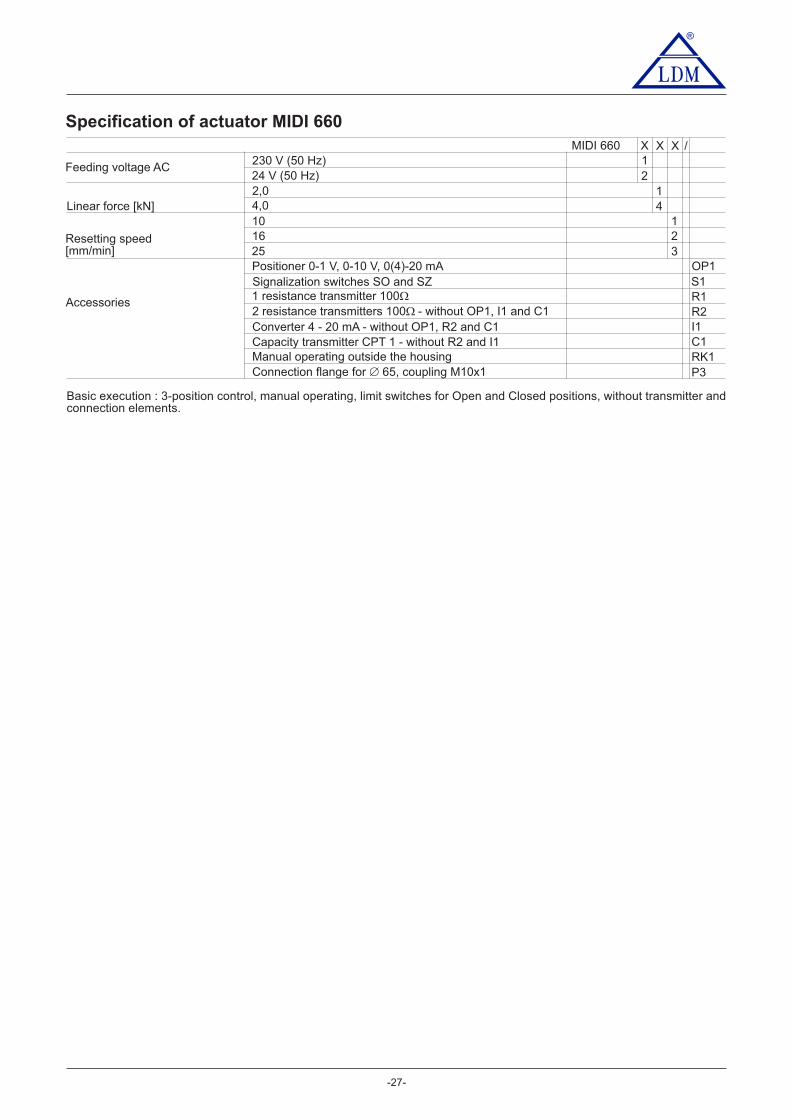
®
-27-
Specification of actuator MIDI 660
230 V (50 Hz)24 V (50 Hz)2,04,010
1 resistance transmitter 100�2 resistance transmitters 100 - without OP1, I1 and C1�
Manual operating outside the housing
1625Positioner 0-1 V, 0-10 V, 0(4)-20 mASignalization switches SO and SZ
Feeding voltage AC
Resetting speed[mm/min]
Linear force [kN]
Accessories
Basic execution : 3-position control, manual operating, limit switches for Open and Closed positions, without transmitter andconnection elements.
MIDI 660
Connection flange for 65, coupling M10x1�
X X X /12
14
123
OP1S1R1R2
RK1P3
Converter 4 - 20 mA - without OP1, R2 and C1 I1Capacity transmitter CPT 1 - without R2 and I1 C1
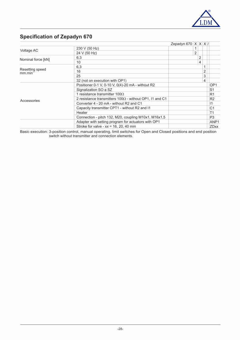
®
-28-
Specification of Zepadyn 670
-1
230 V (50 Hz)24 V (50 Hz)6,3106,3
1 resistance transmitter 100�2 resistance transmitters 100 - without OP1, I1 and C1�Converter 4 - 20 mA - without R2 and C1
162532 (not on execution with OP1)Positioner 0-1 V, 0-10 V, 0(4)-20 mA - without R2Signalization SO a SZ
Voltage AC
Resetting speedmm.min
Nominal force [kN]
Accessories
Zepadyn 670
Capacity transmitter CPT1 - without R2 and I1HeaterConnection - pitch 132, M20, coupling M10x1, M16x1,5
X X X /12
24
1234
OP1S1R1R2I1C1T1P3
Adapter with setting program for actuators with OP1Stroke for valve - xx = 16, 20, 40 mm
ANP1ZDxx
Basic execution: 3-position control, manual operating, limit switches for Open and Closed positions and end positionswitch without transmitter and connection elements.

-29-
®
Electric actuator Zepadyn 671ZPA Nová Paka
ENE
Technical data
Marking in valve specification No.VoltageFrequencyPower consumptionControlNominal forceTravelEnclosureProcess medium max. temperatureAmbient temperature rangeAmbient humidity rangeWeight
ENE230 V AC or 24 V AC50 Hzmax 120 VA, heat resistor 15 W3 - position control, 0 - 10 V, 0(4) - 20 mA16000 and 20000 N40, 80 mmIP 65Acc. to used valve-25 to 55 C10 - 100 % with condensation12,5 kg
Type Zepadyn 671 XXX
o
Specification of Zepadyn 671
-1
230 V (50 Hz)24 V (50 Hz)162016
1 resistance transmitter 100�2 resistance transmitters 100 - without OP1, I1 and C1�Converter 4 - 20 mA - without R2 and C1
253250Positioner 0-1 V, 0-10 V, 0(4)-20 mA - without R2 and I1Signalization SO a SZ
Voltage AC
Resetting speedmm.min
Nominal force [kN]
Accessories
Zepadyn 671
Capacity transmitter CPT1 - without R2 and I1HeaterConnection - pitch 132, M20, coupling M10x1, M16x1,5
X X X /12
12
1234
OP1S1R1R2I1C1T1P3
Adapter with setting program for actuators with OP1Stroke for valve - xx = 40, 80 mm
ANP1ZDxx
Basic execution: 3-position control, manual operating, limit switches for Open and Closed positions and end positionswitch without transmitter and connection elements.
* Connection for LDM valvesP3P5
RV 2xx DN 80 - 150RV 2xx DN 200 - 300
Connection - pitch 150, 4 columns M20, coupling M20x1,5 P5
Note: Specifications and technical data are for information only.Detailed technical informations can be found in producer's data sheet or on the webside www.zpanp.cz
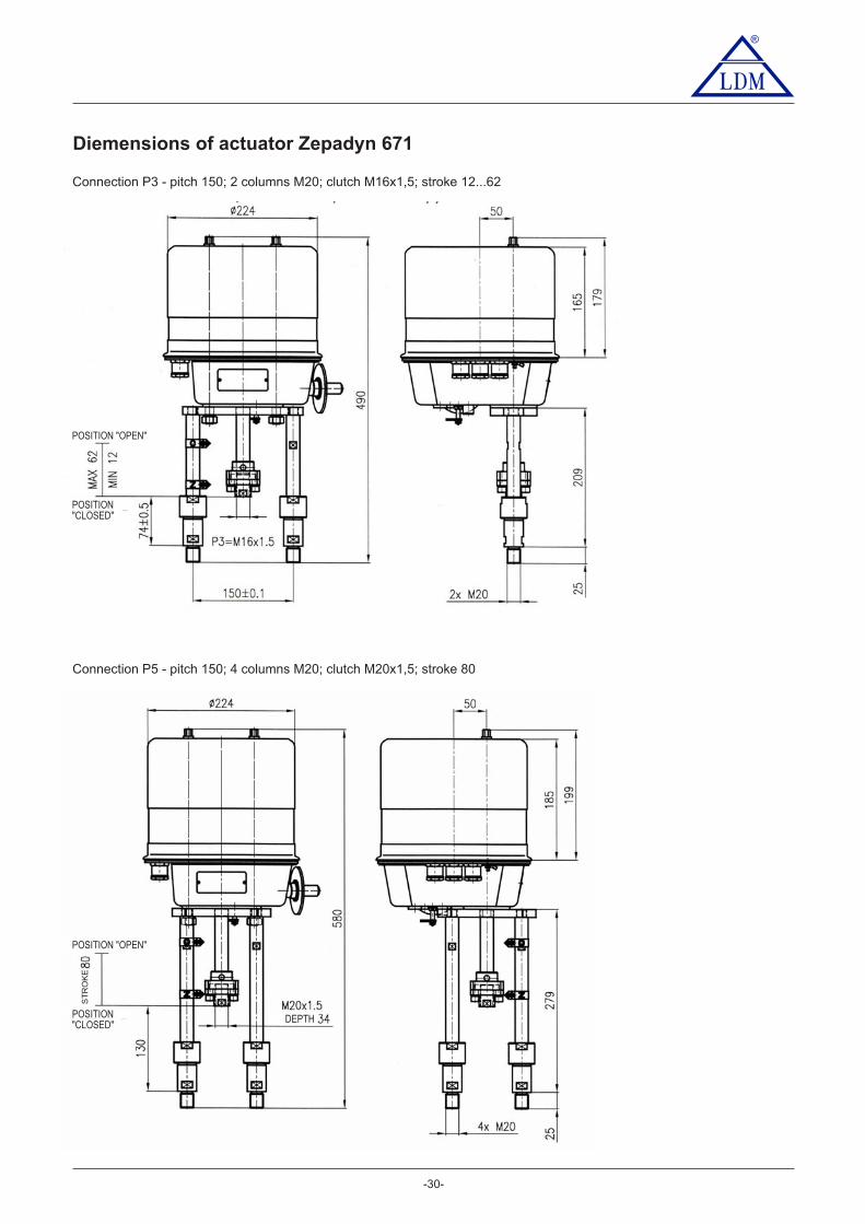
-30-
®
Diemensions of actuator Zepadyn 671
Connection P3 - pitch 150; 2 columns M20; clutch M16x1,5; stroke 12...62
Connection P5 - pitch 150; 4 columns M20; clutch M20x1,5; stroke 80
POSITION "OPEN"
POSITION"CLOSED"
POSITION"CLOSED"
POSITION "OPEN"
DEPTH
ST
RO
KE
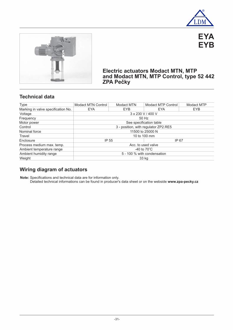
-31-
®
EYAEYB
Electric actuators Modact MTN, MTPand Modact MTN, MTP Control, type 52 442ZPA Pečky
Technical data
Marking in valve specification No.VoltageFrequencyMotor powerControlNominal forceTravelEnclosureProcess medium max. temp.Ambient temperature rangeAmbient humidity rangeWeight
3 x 230 V / 400 V50 Hz
See specification table3 - position, with regulator ZP2.RE5
11500 to 25000 N10 to 100 mm
Acc. to used valve- to C40 70
5 - 100 % with condensation33 kg
Wiring diagram of actuators
Type
o
EYAModact MTN Control
EYAModact MTP Control
EYBModact MTN
EYBModact MTP
IP 55 IP 67
Note: Specifications and technical data are for information only.Detailed technical informations can be found in producer's data sheet or on the webside www.zpa-pecky.cz
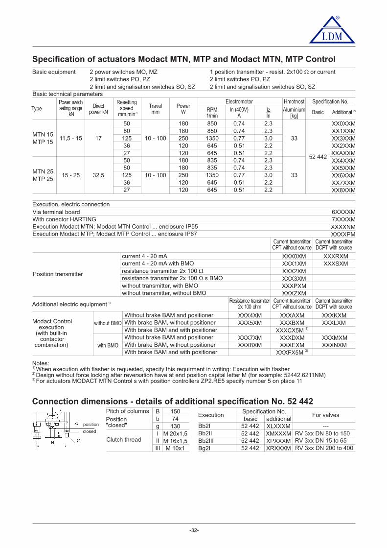
-32-
®
Specification of actuators Modact MTN, MTP and Modact MTN, MTP Control
Basic equipment 2 power switches MO, MZ2 limit switches PO, PZ2 limit and signalisation switches SO, SZ
1 position transmitter - resist. 2x100 or current�2 limit switches PO, PZ2 limit and signalisation switches SO, SZ
Basic technical parameters
Execution, electric connectionVia terminal boardWith conector HARTING
6XXXXM7XXXXM
Position transmitter
Current transmitterDCPT with source
Current transmitterCPT without sourceAdditional electric equipment
Modact Controlexecution
(with built-incontactor
combination)
Without brake BAM and positionerWith brake BAM, without positionerWith brake BAM and with positionerWithout brake BAM and positioner
without BMO
with BMO With brake BAM, without positionerWith brake BAM and with positioner
Notes:When execution with flasher is requested, specify this requirment in writing: Execution with flasher1)
Design without force locking after reversation have at end position capital letter M (for example: 52442.6211NM)2)
For actuators MODACT MTN Control s with position controllers ZP2.RE5 specify number 5 on place 113)
Execution Modact MTN; Modact MTN Control ... enclosure IP55Execution Modact MTP; Modact MTP Control ... enclosure IP67
XXXXNMXXXXPM
Current transmitterDCPT with source
Current transmitterCPT without source
XXXR MXXXXS MX
XXX0 MXXXX1 MXXXX2 MXXXX3 MXXXXP MXXXXZ MX
current 4 - 20 mAcurrent 4 - 20 mA with BMOresistance transmitter 2x 100 �resistance transmitter 2x 100 s BMO�without transmitter, with BMOwithout transmitter, without BMO
Resistance transmitter2x 100 ohm
XXXAXMXXXBXM
XXXCX5M 3)
XXXDXMXXXEXM
XXXFX5M 3)
XXX4XMXXX5XM
XXX7XMXXX8XM
XXXKXMXXXLXM
XXXMXMXXXNXM
2)
1)
Connection dimensions - details of additional specification No. 52 442BbgIIIIII
15074
130M 20x1,5M 16x1,5M 10x1
Pitch of columns
Position"closed"
Clutch thread
Specification No.basic
52 44252 44252 44252 442
additionalXLXXXMXMXXXMXPXXXMXRXXXM
Execution
Bb2IBb2IIBb2IIIBg2I
position
closed
For valves
---RV 3xx DN 80 to 150RV 3xx DN 15 to 65RV 3xx DN 200 to 400
TypePower switchsetting range
kN
Directpower kN
Resettingspeed
mm.min
Travelmm Aluminium Basic Additional
Hmotnost Specification No.
XX0XXMXX1XXM
33 XX3XXMXX2XXMXXAXXM
52 442XX4XXMXX5XXM
33 XX6XXMXX7XXMXX8XXM
11,5 - 15
15 - 25
17
32,5
5080
12536275080
1253627
10 - 100
10 - 100
-1
MTN 15MTP 15
MTN 25MTP 25
PowerW RPM
1/minIn (400V)
AIzIn
Electromotor
180 850 0.74 2.3180 850 0.74 2.3250 1350 0.77 3.0120 645 0.51 2.2120 645 0.51 2.2180 835 0.74 2.3180 835 0.74 2.3250 1350 0.77 3.0120 645 0.51 2.2120 645 0.51 2.2
[kg]

Detail of coupling
- ONLY AFTER AGREEMENT WITH PRODUCER
Dimensions of actuatorModact MTN, MTP
Dimensions of actuator Modact MTN,MTP and Modact MTN, MTP Control
®
-33-
- with conector
Provedení 2A 160B 150a 30b 74g 130
c (a) 308d (b) 352h (g) 408e (a) 605f (b) 649
ch (g) 705
Provedení 2A 160B 150a 30b 74g 130
c (a) 308d (b) 352h (g) 408e (a) 633f (b) 677
ch (g) 733
Provedení 2A 160B 150a 30b 74g 130
c (a) 308d (b) 352h (g) 408e (a) 633f (b) 677
ch (g) 733
- with terminal board
max. 595max. 334 261
325
e(a)
, f(b
), c
h(g
)
c(a)
, d(b
), h
(g)
253
100
(153
)a,
b,g M20 ø 26
25
215
99 90
AB Execution 2
ø cable 9 - 16 mmEXTERNAL PROTECTING CLAMP
LOCAL CONTROL
1x CABLE GLAND M25x1,5
215
M25x1,5ø cable 13 – 18
M20x1,5ø cable 10 – 14
LOCAL CONTROL
99 90
M 20
325
ø 26A
B Execution 2
a, b
, g25
3
max. 595261max. 334
(153
)10
0
25
c (a
), d
(b
), h
(g
)
ø cable 9 – 16 mm1 x CABLE GLAND M25x1,5
M 20
297
ø26AB Execution 2
e (a
), f
(b
), c
h (
g)
a, b
, g25
3
215
99 90 97
max. 562228max. 334
(153
)10
0
25
c (a
), d
(b
), h
(g
)
cable 9 – 16 mmøLOCAL CONTROL
1x CABLE GLAND M25x1,5 EXTERNAL PROTECTING CLAMP
Dimensions of actuator Modact MTN, MTP Control
Execution 2A 160B 150a 30b 74g 130
c (a) 308d (b) 352h (g) 408e (a) 633f (b) 677
ch (g) 733
Execution 2A 160B 150a 30b 74g 130
c (a) 308d (b) 352h (g) 408e (a) 605f (b) 649
ch (g) 705
Execution 2A 160B 150a 30b 74g 130
c (a) 308d (b) 352h (g) 408e (a) 633f (b) 677
ch (g) 733
- with terminal board
EXTERNAL PROTECTING CLAMP
Threadsor bushings
e (a
), f
(b
), c
h (
g)
Threadsor bushings
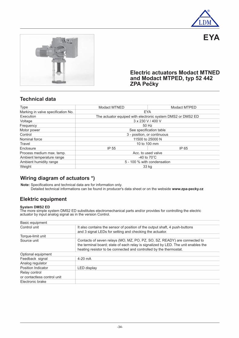
-34-
®
EYA
Electric actuators Modact MTNEDand Modact MTPED, typ 52 442ZPA Pečky
Technical data
Marking in valve specification No.
VoltageFrequencyMotor powerControlNominal forceTravelEnclosureProcess medium max. temp.Ambient temperature rangeAmbient humidity rangeWeight
3 x 230 V / 400 V50 Hz
See specification table3 - position, or continuous
11500 to 25000 N10 to 100 mm
Acc. to used valve- to C40 70
5 - 100 % with condensation33 kg
Wiring diagram of actuators *)
Type
o
IP 55 IP 65
EYAModact MTNED Modact MTPED
Execution The actuator equiped with electronic system DMS2 or DMS2 ED
Elektric equipment
System DMS2 EDThe more simple system DMS2 ED substitutes electromechanical parts and/or provides for controlling the electricactuator by input analog signal as in the version Control.
Torque-limit unit
Optional equipmentF signaleedbackAnalog regulatorPosition IndicatorRelay controlor contactless control unitElectronic brake
Control unit
Source unit
It also contains the sensor of position of the output shaft, 4 push-buttonsand 3 signal LEDs for setting and checking the actuator.
Contacts of seven relays (MO, MZ, PO, PZ, SO, SZ, READY) are connected tothe terminal board; state of each relay is signalized by LED. The unit enables theheating resistor to be connected and controlled by the thermostat.
4-20 mA
LED display
Basic equipment
Note: Specifications and technical data are for information only.Detailed technical informations can be found in producer's data sheet or on the webside www.zpa-pecky.cz

-35-
®
System DMS2The system DMS2 enables the electric actuator to be used for two-position and three-position regulation or to beconnected to the industrial bus bar Profibus.
Torque-limit unit
Recommended equipmentElectronic brakeOptional equipment (the electric actuator must be fitted with one of these units)
Unit of two- and three-positioncontrolUnit of connection Profibus
Note: The electronic control DMS2 checks, within its function, sequence and fall-out of phases of supply voltage.
Control unit
Source unit
It also includes a sensor of the output shaft position2 signal LED
- 2 relays for electric motor control- Relay with change-over contact connected to the terminal boardReady
- Signalling relays 1 - 4 with one pole of the switching contact connected to the terminal board
After switching-off the motor reduces running down and precises the control
Control of the electric actuator by shifting to position Open and Close
Basic equipment
Second poles of the switching contacts of relays 1 - 4 are interconnected
Heating resistor switched by a thermostat is connected to the unitThe unit controls power switches of the electric motor (reversing relay)To the unit can be connected an electronic brake
Unit of displayUnit of push-buttons
Two-row display, 2 x 12 alpha-numeric charactersPush-buttons Selector switch"Open", "Close", "Stop"; "Local", "Remote", "Stop"
or by analog signal 0(4) - 20 mAControl of the electric actuator by industrial bus bar Profibus
Specification of actuators Modact MTNED a MTPED
Basic technical parameters
TypePower switchsetting range
kN
Directpower kN
Resettingspeed
mm.min
Travelmm Basic Additional
Weight Specification No.
33
52 442
33
11,5 - 15
15 - 25
17
32,5
5080
12536275080
1253627
10 - 100
10 - 100
Execution Modact MTNED ... enclosure IP55Execution Modact MTPED ... enclosure IP67
-1
MTNED 15
MTPED 15
MTNED 25
MTPED 25
PowerW RPM
1/minIn (400V)
AIzIn
Electric Motor
180 850 0.74 2.3180 850 0.74 2.3250 1350 0.77 3.0120 645 0.51 2.2120 645 0.51 2.2180 835 0.74 2.3180 835 0.74 2.3250 1350 0.77 3.0120 645 0.51 2.2120 645 0.51 2.2
Execution, circuity, electronic equipment
DMS2, ED electronicsDMS2, Profibus electronicsDMS2, 2-position or 3-position control *)
KXXXXEDYXX0XED
HXXXXEDUXX0XEDWXX0XED
FXXXXEDTXX0XEDVXX0XED
EXXXXEDPXX0XEDRXX0XED
brakeConectorTerminal boardTerminal board,
brakeConector,
*) Producer will set in production 2- or 3- position control. If not specified in the order,
Equipment Character at the 9. position (52 442 xxxXxED)0 1 2 3 4 5 6 7 8 9 A B C D E F H J K L M N P R
x xxx
x x
xxx
xx
x
x x
xx
x x
xx
xx
xx
x
xx
x xx
x
x xx
xx
x
x
x xx
xx
xxx
xxx
x
xxx
xxxx
xx
Equipment of DMS2ED electronics
Local controlDisplayRelay
Analog module TransmitterRegulator
Note: In the case of using an electronic DMS2 is the character at the 9. position 0
Aluminium[kg]
1XX0XED
and brought out to the terminal COM
the gearmotor is set to 3-position control (signal control 4-20 mA).
XX0XXEDXX1XXEDXX3XXEDXX2XXEDXXAXXEDXX4XXEDXX5XXEDXX6XXEDXX7XXEDXX8XXEDXXXXNEDXXXXPED
x
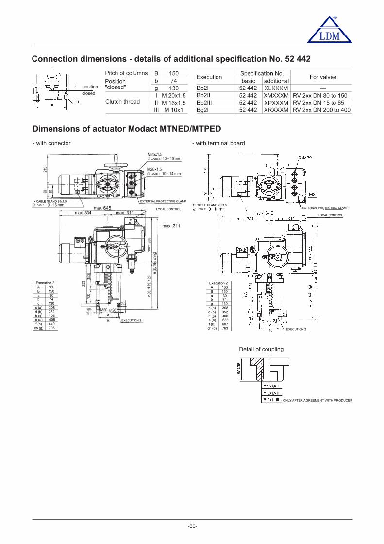
-36-
®
Dimensions of actuator Modact MTNED/MTPED
- with conector - with terminal board
Execution 2A 160B 150a 30b 74g 130
c (a) 308d (b) 352h (g) 408e (a) 605f (b) 649
ch (g) 705
Execution 2A 160B 150a 30b 74g 130
c (a) 308d (b) 352h (g) 408e (a) 633f (b) 607
ch (g) 763
Connection dimensions - details of additional specification No. 52 442
BbgIIIIII
15074
130M 20x1,5M 16x1,5M 10x1
Pitch of columns
Position"closed"
Clutch thread
Specification No.basic
52 44252 44252 44252 442
additionalXLXXXMXMXXXMXPXXXMXRXXXM
Execution
Bb2IBb2IIBb2IIIBg2I
position
closed
For valves
---RV 2xx DN 80 to 150RV 2xx DN 15 to 65RV 2xx DN 200 to 400
1x CABLE GLAND 25x1,5CABLE
EXTERNAL PROTECTING CLAMP
LOCAL CONTROL
CABLE
CABLE
EXECUTION 2
EXTERNAL PROTECTING CLAMP
LOCAL CONTROL
1x CABLE GLAND 25x1,5CABLE
EXECUTION 2
Detail of coupling
- ONLY AFTER AGREEMENT WITH PRODUCER

-37-
®
Electric actuatorsSA 07.2, SA Ex 07.2, SAR 07.2, SAR Ex 07.2SA 07.6, SA Ex 07.6, SAR 07.6, SAR Ex 07.6Auma
Specification of Auma actuators
TypeSA XXX 07.X
ControlDuty
R
Actuator´s size
ExC07.1
X
ON - OFFStandard
SA
ExecutionNon-explosive
Technical data
07.5
Note: www.auma.comSpecifications and technical data are for information only. Detailed technical informations can be found in producer's data sheet or on the webside
Marking in valve specification No.VoltageFrequencyMotor powerControlNominal forceTravelEnclosureProcess medium max. temperat.Ambient temperature rangeAmbient humidity limitWeight of 1-phaseWeight of 3-phase
EAD1 ~ 230 V AC; 3 ~ 380 nebo 400 V AC
50 HzSee specification table
3 - position control or with signal 4 - 20 mA30 Nm 15 kN; 40 Nm 20 kN~ ~
Acc. to valve stroke 16, 25, 40 mm
Acc. to used valve
100 %
TypEAA EAB EAC
IP 68
EAHEAE EAF EAG
10 Nm 5 kN; 15 Nm 7,5 kN; 20 Nm 10 kN~ ~ ~Acc. to valve stroke 40, 80, 100 mm
SAR Ex 07.2SA 07.2 SA Ex 07.2 SAR 07.2 SAR Ex 07.6SA 07.6 SA Ex 07.6 SAR 07.6
-40 to 80°C -20 to 60°C -40 to 60°C -20 to 60°C -40 to 80°C -20 to 60°C -40 to 60°C -20 to 60°C
25-62 kg20-33 kg
25-62kg21-33kg
EAA, EAB, EAC, EADEAE, EAF, EAG, EAH
4
Out
put s
peed
(rp
m)
Trip
ping
torg
ue5,681116223245
SA 07.2S2-15min
SA Ex 07.2S2-15min
SAR 07.2S4-25%
SAR Ex 07.2S4-25%
SA 07.2 SAR 07.2
SAEx 07.2 SAREx 07.2
Mot
or p
ower
[ kW
]
10-30Nm
15-30Nm
0,02 0,02 0,02 0,020,02 0,02 0,02 0,020,04 0,04 0,04 0,040,04 0,04 0,04 0,040,06 0,06 0,06 0,060,06 0,06 0,06 0,060,10 0,10 0,10 0,100,10 0,10 0,10 0,10
Output shaft type A (thread TR 16x4 LH, connection flange F07) ... for RV 3xx DN 15 to 65
4
Out
put s
peed
(rp
m)
Trip
ping
torg
ue5,681116223245
SA 07.6S2-15min
SA Ex 07.6S2-15min
SAR 07.6S4-25%
SAR Ex 07.6S4-25%
SA 07.6 SAR 07.6
SAEx 07.6 SAREx 07.6
Mot
or p
ower
[ kW
]
20-60Nm
30-60Nm
0,03 0,03 0,03 0,030,03 0,03 0,03 0,030,06 0,06 0,06 0,060,06 0,06 0,06 0,060,12 0,12 0,12 0,120,12 0,12 0,12 0,120,20 0,20 0,20 0,200,20 0,20 0,20 0,20
Output shaft type A (thread TR 20x4 LH, connection flange F10) ... for RV 3xx DN 80 to 400

-38-
®
Dimension of Auma actuators 07.2 / 07.6
Other accessories acc. to catalogue of producer of actuators.
Accessories
2 TANDEM switchesGearing for signalisation of positionMechanical position indicatorPotentiometer 1x200 �Electronic position transmitter RWG (potentiometer included), 4 - 20 mA, 2-wireElectronic position transmitter RWG (potentiometer included), 4 - 20 mA, 3/4-wireInductive position transmitter IWG, 4 - 20 mAMATIC - for continuous control (specification of accessories acc. to catalogue of producer)AUMATIC - for continuous control (specification of accessories acc. to catalogue of producer)
Normal execution ExC norm execution
Execution MATIC Execution Ex MATIC
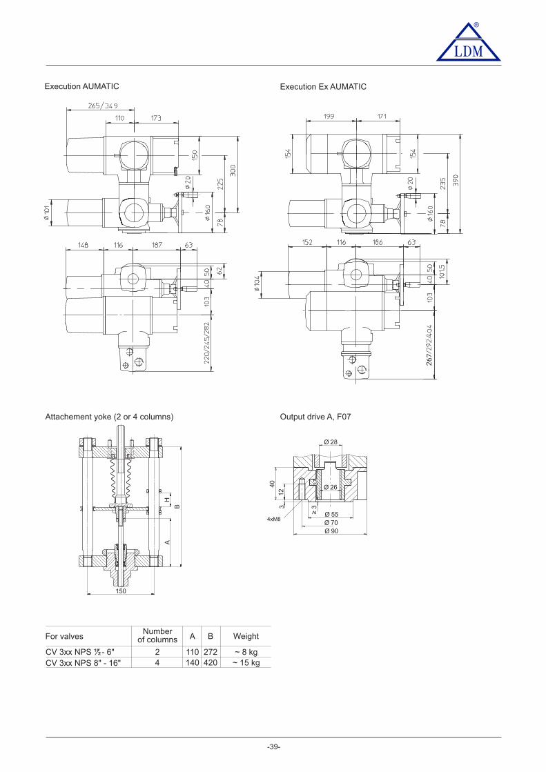
Output drive A, F07
Ø 28
Ø 26
≥33
40
12
Ø 55Ø 70Ø 90
37
4xM8
-39-
Execution AUMATIC Execution Ex AUMATIC
®
Attachement yoke (2 or 4 columns)
A
B
H
150
110 272
A B
2
Numberof columns
140 4204
For valves
CV 3xx NPS ½" - 6"C 3V xx NPS 8" - 16"
~ 8 kg
Weight
~ 15 kg
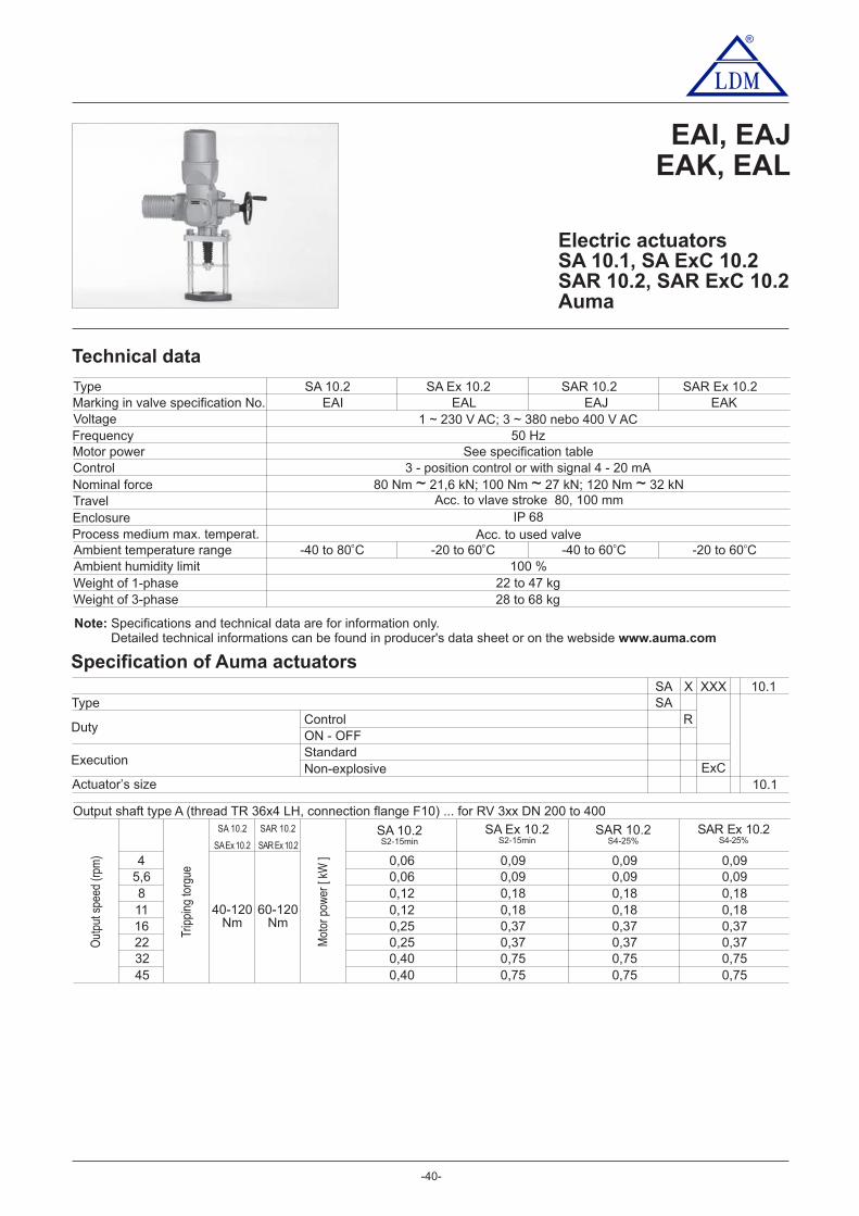
-40-
®
Electric actuatorsSA 10.1, SA ExC 10.2SAR 10.2, SAR ExC 10.2Auma
Specification of Auma actuators
TypeSA XXX 10.1
ControlDuty
R
Actuator s size’ExC
10.1
X
ON - OFFStandard
SA
ExecutionNon-explosive
Technical data
Marking in valve specification No.VoltageFrequencyMotor powerControlNominal forceTravelEnclosureProcess medium max. temperat.Ambient temperature rangeAmbient humidity limit
Type
Output shaft type A (thread TR 36x4 LH, connection flange F10) ... for RV 3xx DN 200 to 400
EAI, EAJEAK, EAL
4
Out
put s
peed
(rp
m)
Trip
ping
torg
ue5,681116223245
SA 10.2 SAR 10.2
SAEx 10.2 SAREx 10.2
Mot
or p
ower
[ kW
]
40-120Nm
60-120Nm
0,060,060,120,120,250,250,400,40
0,090,090,180,180,370,370,750,75
0,090,090,180,180,370,370,750,75
0,090,090,180,180,370,370,750,75
SA 10.2S2-15min
SA Ex 10.2S2-15min
SAR 10.2S4-25%
SAR Ex 10.2S4-25%
EAK
50 HzSee specification table
3 - 4 - 20 mAposition control or with signal80 Nm 21,6 kN; 100 Nm 27 kN; 120 Nm 32 kN~ ~ ~
Acc. to used valve
100 %
EAI EAL EAJ
IP 68
SAR Ex 10.2SA 10.2 SA Ex 10.2 SAR 10.2
- 80 C40 to o - 0 C20 to 6 o - 60 C40 to o -2 0 C0 to 6 o
22 4to 7 kg28 to 68 kg
1 ~ 230 V AC; 3 ~ 380 nebo 400 V AC
Weight of 1-phaseWeight of 3-phase
Acc. to vlave stroke 80, 100 mm
Note: Specifications and technical data are for information only.Detailed technical informations can be found in producer's data sheet or on the webside www.auma.com
®

®
-41-
Other accessories acc. to catalogue of producer of actuators.
Accessories
2 TANDEM switchesGearing for signalisation of positionMechanical position indicatorPotentiometer 1x200 �Electronic position transmitter RWG (potentiometer included), 4 - 20 mA, 2-wireElectronic position transmitter RWG (potentiometer included), 4 - 20 mA, 3/4-wireInductive position transmitter IWG, 4 - 20 mAAUMATIC - for continuous control (specification of accessories acc. to catalogue of producer)
Dimension of Auma actuators 10.1
Normal execution ExC norm execution
Version MATIC / AUMATIC Execution Ex MATIC
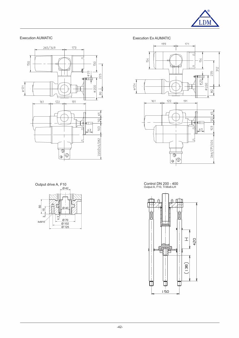
Output drive A, F10 Control DN 200 - 400Output A, F10, Tr36x6-LHØ 42
Ø 40
≥33
5015
Ø 70Ø 102Ø 125
47
4xM10
Execution AUMATIC Execution Ex AUMATIC
®
-42-

Output shaft thread ange( TR 16x4 LH, fl F07 ... DN 15 to 150 thread TR 20x4 LH, flange F10 ... DN 80 to 400 );
®
Electric actuators ...AB3, ...AB5Schiebel
EZA, EZBEZC, EZD
EZG, EZHEZE, EZF
-43-
Technical data
Mark in valve´s spec. No.VoltageFrequencyMotor powerControlNominal forceStrokeEnclosureProcess medium max. t.Ambient temp. rangeAmbient humidity limitWeight
EZD400 / 230 V; 230 V
50 HzSee specification table
3 - position control of continuous 4 - 20 mA80 Nm 32 kN~
Acc. to the valve stroke 16, 20, 40, 80, 100 mmIP 66
Acc. to used valve-25 to 80 C
90 % (tropical version: 100 % with condensation)
Specification of actuators
Type exrAB3EZAAB3
EZBexAB3
EZCrAB3
400 / 230 V; 230 V400 / 230 V 400 / 230 V
IP 65 IP 66 IP 65
-20 to 40 C -25 to 60 C -20 to 40 C
Non-explosiveX AB3 X + XXX
Standard
DutyR
AB5A
AXX
Execution
ControlON - OFF
Ex
400/230V
2,5
Out
put s
peed
(rp
m)
Trip
ping
torg
ue
57,51015203040
FFFESM21CMR
230V 400/230V 230V
AB5 rAB5 exAB5 exrAB5AB5 rAB5exAB5 exrAB5
2,55
7,51015203040
Mot
or p
ower
[ kW
]
Accessories
Potentiometer 1x1000 �Double potentiometerElectronic transmitter 4 - 20 mAPositioner ACTUMATIC R
10-60Nm
400/230V400/230V
16 - 20 kg
o o o o
EZHexrAB5
EZEAB5
EZFexAB5
EZGrAB5
AB3Actuator´s torque
400/230V
2,5
Out
put s
peed
(rp
m)
Trip
ping
torg
ue57,51015203040
230V 400/230V 230V
AB3 rAB3 exAB3 exrAB3AB3 rAB3exAB3 exrAB3
2,55
7,51015203040
Mot
or p
ower
[ kW
]
10-30Nm
400/230V400/230V
0,090,120,090,090,090,090,180,18
0,090,120,090,090,090,090,370,37
0,090,120,090,090,180,370,250,55
0,090,030,090,090,090,090,180,18
0,090,120,090,090,090,180,250,25
0,090,030,090,090,180,180,180,18
Tripping7 - 30Nm
Loading7 - 15Nm
Tripping30 - 60
Nm
Loading15 - 30
Nm
CSCSMARTCON control unit
0,090,120,090,090,180,180,370,37
0,090,120,090,090,180,180,370,37
0,090,120,180,370,370,751,101,10
0,090,060,090,090,180,180,370,37
0,090,120,090,180,180,550,550,55
0,090,060,090,090,180,180,370,37
Note: www.schiebel.czSpecifications and technical data are for information only. Detailed technical informations can be found in producer's data sheet or on the webside

®
110 272
A B
2
No.of columns
140 4204
For valves
CV 3xx NPS ½” - 6"C 3xx NPS 8" - 16"V
~ 8 kg
Weight
~ 15 kg
-44-
Dimensions of actuators ...AB3, ...AB5
Attachement yoke (2 or 4 columns)
A
B
H
150
Output drive A, flange F10
Output drive A, flange F07
With ACTUMATIC R positioner
With SMARTCON control unit
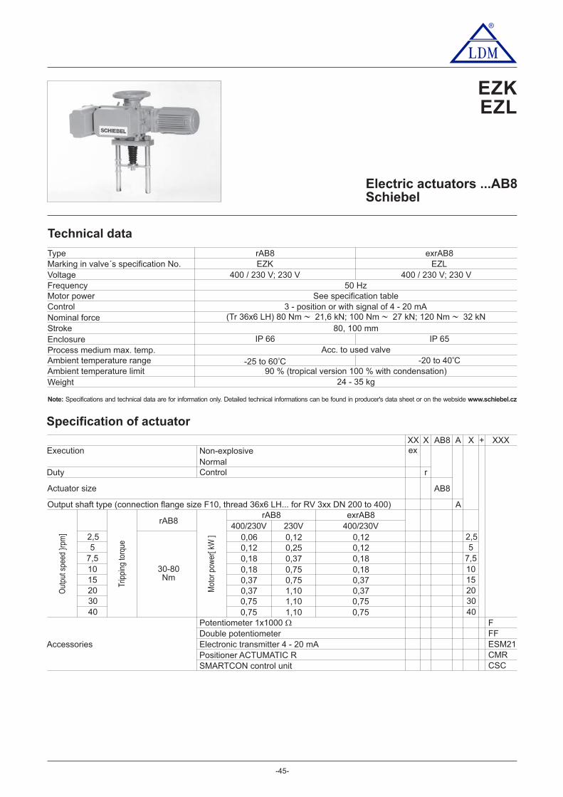
®
- -45
Electric actuators ...AB8Schiebel
Technical data
Marking in valve´s specification No.VoltageFrequencyMotor powerControlNominal forceStrokeEnclosureProcess medium max. temp.Ambient temperature rangeAmbient temperature limitWeight
50 HzSee specification table
3 - position or with signal of 4 - 20 mA
80, 100 mm
Acc. to used valve
90 % (tropical version 100 % with condensation)
Specification of actuator
Type
400 / 230 V; 230 V
X AB8 X + XXXNon-explosive
Duty r
Output shaft type (connection flange size F10, thread x36 6 LH... for 3 2 to 400RV xx DN 00 )
AB8
A
AXXExecution
Control
2,5
Out
put s
peed
}rp
m]
Trip
ping
torq
ue57,51015203040
FFFESM21CMR
rAB8
2,55
7,51015203040
Mot
or p
ower
[ kW
]
Accessories
Potentiometer 1x1000 �Double potentiometerElectronic transmitter 4 - 20 mAPositioner ACTUMATIC R
30-80Nm
IP 66
-25 to 0 C6 o
24 kg- 35
EZKrAB8
Actuator size
EZKEZL
IP 65
-2 to 0 C0 4 o
EZLexrAB8
400 / 230 V; 230 V
Normalex
rAB8230V0,120,250,370,750,751,101,101,10
400/230V0,060,120,180,180,370,370,750,75
exrAB8400/230V
0,120,120,180,180,370,370,750,75
CSCSMARTCON control unit
(Tr 36x6 LH) 80 Nm 21,6 kN; 100 Nm 27 kN; 120 Nm 32 kN
Note: www.schiebel.czSpecifications and technical data are for information only. Detailed technical informations can be found in producer's data sheet or on the webside
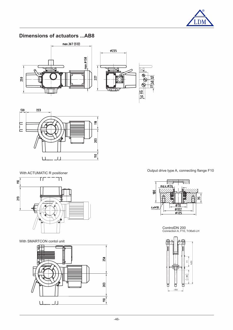
®
- -46
Output drive type A, connecting flange F10
ControlDN 200Connection A, F10, Tr36x6-LH
Dimensions of actuators ...AB8
With ACTUMATIC R positioner
With SMARTCON contol unit
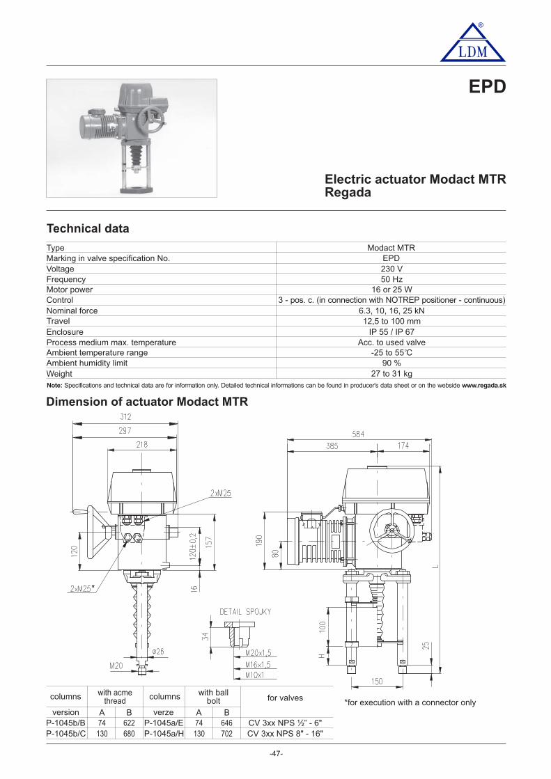
®
-47-
Dimension of actuator Modact MTR
P-1045 /Bb
with acmethread
with ballbolt
74 622 74 646
A B A B
columns
P-1045a/E
columns
verzeversion
P-1045 /b C 130 680 130 702P-1045a/H
for valves
CV 3xx NPS ½” - 6"C 3 NPS 8" - 16"V xx
Electric actuator Modact MTRRegada
EPD
Technical data
Marking in valve specification No.VoltageFrequencyMotor powerControlNominal forceTravelEnclosureProcess medium max. temperatureAmbient temperature rangeAmbient humidity limitWeight
EPD230 V50 Hz
16 or 25 W3 - pos. c. (in connection with NOTREP positioner - continuous)
6.3, 10, 16, 25 kN12,5 to 100 mm
IP 5 IP 65 / 7Acc. to used valve
-25 to 5 C590 %
27 to 31 kg
Type Modact MTR
o
Note: www.regada.skSpecifications and technical data are for information only. Detailed technical informations can be found in producer's data sheet or on the webside
*
*for execution with a connector only

-48-
®
) State the switching-off thrust in your order by words. If not stated it is adjusted to the maximum rate of the corresponding32range. The load torgue equals minimally the maximum switching-off thrust of the choosing range multiplied by 1.3.) The maximum load thrust equals the max. Switching-off thrust multiplied by:33- 0.8 for duty cycle S2-10 min., r S4-25%, 6 - 90 cycles per houro- 0.6 for duty cycle S4-25%, 90 - 1200 cycles per hour) The thread in the coupling is to be specified in the order by words.62
Notes:
Specification of Modact MTR
Electric actuator MTR, linear 52 420. X X X X / X X
Standard
Tropical
016
XX -
Electric conectionTo terminal boardTo connector
Voltage
Enclosure IP 55
230 V AC98
Single
Double
Connection Output
Control board version
80 mm100 mm
Operating stroke
GH
Transmitter
Without transmitter
Resistive
Resistive withcurrent converter
CapacitiveCPT
Without power supply
With power supply
Without power supplyWith power supply
— — A
—
2-wire
3-wire
3-wire
2-wire
2-wire
1x100 Ω1x2000 Ω2x100 Ω
2x2000 Ω4 - 20 mA0 - 20 mA
0 - 20 mA
4 - 20 mA
4 - 20 mA
4 - 20 mA
BFCPSTVQ
WU
IJ
Dimensionaldrawing
150/ —B
Pillar spacing /Bore of flange
Thread ofstem 62)
Mechanicalconnection
Connectinghight / stroke
M16x1.5,M20x1,5,M10x1
ColumnsP-1045 /B; P-1045 /Eb b74/100
130/100Additional equipment
AWithout additional equipment; adjusted max. switching-off thrust from range2 additional position switches S5,S6 0
0 12
Ele tromotorcPower Speed Current
0.31 A
0.41 A
0.31 A
0.41 A
1 150
1 250
1 150
1 250
16 W
25 W
16 W
25 W
A
CDEF
HJK
10 000/32
16 000/32-G10 000/ -G50
16 000/50-G10 000/63-G6 300/100-G
6 300/50
4.0 - 6.3 kN
6.3 - 10.0 kN
10.0 - 16.0 kN6.3 - 10.0 kN
10.0 - 16.0 kN6.3 - 10.0 kN4.0 - 6.3 kN
4.0 - 6.3 kN
Rated speedcontrol
RunningspeedScrew version Nominal
force 32) 33)
6 300/32
trap
ezoi
dal
thre
adba
ll sc
rew
32 mm/min.
32 mm/min.
32 mm/min.50 mm/min.
50 mm/min.63 mm/min.
100 mm/min.
50 mm/min.
38 - 32 mm/min.
38 - 32 mm/min.
38 - 32 mm/min.60 - 50 mm/min.
60 - 50 mm/min.75 - 63 mm/min.
120 - 100 mm/min.
60 - 50 mm/min.
B2.5 - 4.0 kN4 000/50 50 mm/min. 60 - 50 mm/min.
G25 32000/ -G 10.0 - kN25.0 32 mm/min. 38 32- mm/min.
Electromechanical control board -without local control
16 mm25 mm (for stroke 20 mm)
BC
40 mm E
CP-1045 / ; P-1045 /b C b H
Enclosure IP 67Enclosure IP 67
-25°C to +55°C
-25°C to +55°C

®
-49-
Dimensions of actuators
Coupling dimensions
Electric actuatorsST 0, STR 0Regada
EPK
Technical data
EPK
50 Hz1 W
3 - position (0 - 10 V, (0)4 - 20 mA)2,5 kN
16, 20 mmIP 54 / IP 67
acc. to used valve-25 to 55 C
5 - 100% with condensation2,5 to 4,5 kg
ST 0, STR 0
230 V AC, 24 V AC
o
Marking in valve specification No.VoltageFrequencyMotor powerControlNominal forceTravelEnclosureProces medium max. temperatureAmbient temperature rangeAmbient humidity rangeWeight
Type
1) Applies to execution with electronic transmitter
Note: www.regada.skSpecifications and technical data are for information only. Detailed technical informations can be found in producer's data sheet or on the webside

®
-50-
Specification of actuator ST 0, STR 0
Electric actuator Isomact ST 0, STR 0 490. X X X X / X X
230 V AC24 V AC
16 mm/min2900 37)
X - X
1
3
P
Electric connection0
2,75 W
Travel
00Accessories
To terminal board Voltage
Without transmitter A
6AG
Rem
ote
posi
tion
tran
smitt
er
Wiri
ng
Fee
dbac
kBF
1 x 100 Ω1 x 2000 Ω
SQT
VU
W
Resistance
4 - 20 mA
4 - 20 mA
0 - 20 mA
2-wire2-wire 6)
3-wire 6)
Mechanical connection - flange, connecting height 110 mm, thread on con. stem M10x1 L
2 auxiliary position switches
0
10 mm/min4500 37) NRunning speed Motor power
2,75 W5 mm/min4500 A2,75 W4 mm/min2900
IP 67IP 67
IP 67
IP 54Without regulator (ST 0)
With regulator (STR 0) resistive feedbackIP 54
0Nominal force [ N ]
1 W
single
Electronic- current
(without generator)
Tripping torque DE
16 mm2 mm0
One-torque
Resistancetosurroundings
Standard
StandardTropical
Tropical
6) Applies for the version without any positioner.16) Feedback to the positioner is realised by resistive transmitter (without selection of the order code for transmitter).37) Applies for temperature range -15 up to +55°C and for voltage Un -5% up to Un +10%.76) The version with a positioner and with a lead-out transmitter cannot be speciffied also 2 additional position switches (S5, S6).
-25°C to +55°C
-25°C to +55°C-25°C to +55°C-25°C to +55°C
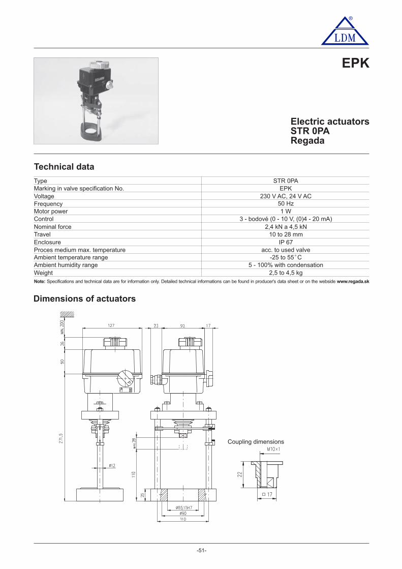
®
-51-
Electric actuatorsSTR 0PARegada
EPK
Technical data
Dimensions of actuators
acc. to used valve-25 to 55 C
5 - 100% with condensation2,5 to 4,5 kg
o
Marking in valve specification No.VoltageFrequencyMotor powerControlNominal forceTravelEnclosureProces medium max. temperatureAmbient temperature rangeAmbient humidity rangeWeight
TypeEPK
1 W3 - bodové (0 - 10 V, (0)4 - 20 mA)
2,4 kN a 4,5 kN10 to 28 mm
IP 67
STR 0PA
230 V AC, 24 V AC50 Hz
Coupling dimensions
Note: www.regada.skSpecifications and technical data are for information only. Detailed technical informations can be found in producer's data sheet or on the webside

®
-52-
Electric actuatorsST 0.1, STR 0.1Regada
EPL
Dimensions of actuators
Technical data
EPL
50 Hz15W, 20W
3 - position control (0 - 10 V, 4 - 20 mA)4,6 a 7,2 kN
16, 20, 40 mmIP 65 / IP 67
Acc. to used valve-25 to 55 C
5 - 100% with condensation5,4 to 8 kg
ST 0.1, STR 0.1
230 V AC, 3 x 400 V AC, 24 V AC, 24 V DC
o
Marking in valve specification No.VoltageFrequencyMotor powerControlNominal forceTravelEnclosureProces medium max. temperatureAmbient temperature rangeAmbient humidity rangeWeight
Type
Note: www.regada.skSpecifications and technical data are for information only. Detailed technical informations can be found in producer's data sheet or on the webside
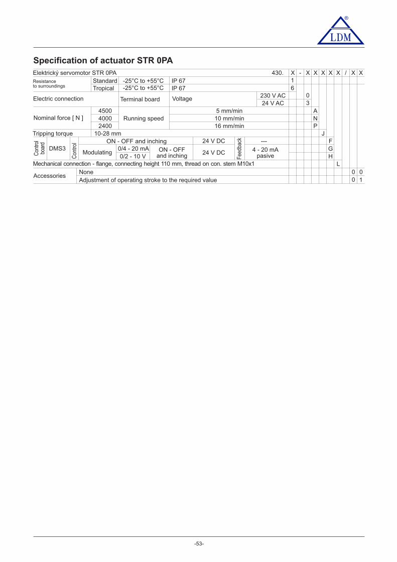
®
-53-
Specification of actuator STR 0PA
Elektrický servomotor STR 0PA 430.IP 67
X X X X / X X
230 V AC24 V AC
24 V DC
24 V DC
16 mm/min2400
X - X
3
P
Electric connection 0
Tripping torque
010
0Accessories
Terminal board Voltage
Con
trol
F
Con
trol
boar
d
Fee
dbac
k
GH
ON - OFF and inchingDMS3
Modulating ON - OFFand inching
4 - 20 mApasive
0/4 - 20 mA0/2 - 10 V
---
Mechanical connection - flange, connecting height 110 mm, thread on con. stem M10x1 LNoneAdjustment of operating stroke to the required value
1
10 mm/min4000 NRunning speed5 mm/min4500 A
Nominal force [ N ]
J10-28 mm
IP 67Resistanceto surroundings
StandardTropical
-25°C to +55°C-25°C to +55°C 6

®
-54-
Specification of actuator ST 0.1, STR 0.1
Electric actuator ST 0.1, STR 0.1 498. X X X X / X X
230 V AC
230 V AC
24 V AC
24 V AC
24 V DC
24 V DC
10 mm/min16 mm/min
4600
Tripping torque
25 mm/min32 mm/min
Without transmitter A
6ACGJ
X - X
3
8
A
C
G
IJ
DEH
Electric connection
0
5
Nom
inal
forc
e[ N
]
Runnin
gsp
eed
Mot
or p
ower
H
Travel16 mm2 mm040 mm
Rem
ote
posi
tion tra
nsm
itter
Wirin
g
Feedback
IJ
CapacityWo. its source
With its source4 - 20 mA
30C
BFKP
1 x 100 Ω1 x 2000 Ω2 x 100 Ω
2 x 2000 ΩSQTU
Resistance
4 - 20 mA
0 - 20 mA
W
Terminal board
Na konektor
Voltage
40 mm/min10 mm/min16 mm/min25 mm/min
40 mm/min
TU
K
V
Y
7200
Two-torque
Wo. its source
2 - wire
2 - wire
2 - wire6)
2 - wire6)
Mechanical connection - flange, connecting height 110 mm, thread on con. stem M10x1 or M16x1,5 C
Accessories
1IP 65IP 67IP 67IP 65IP 65IP 67IP 67
0
32 mm/min W
Single
Double6)
V4 - 20 mA
Electronic- current
With its source
0010
AB
Heater without thermal sensor
2 auxiliary position switches 8)
Without space heater
3x380 V AC6)
3x380 V AC6)
3x400 V AC6)
3x400 V AC6)
M
R
9
7
50D Manual control without pernament standby
3 - wire6)
---
---
Allowed combination of accessories and codes:A+B=02, A+C=04, A+D=06, B+D=07, A+B+D=08, C+D=09, A+C+D=10
Without positioner (ST 0.1)
With positioner (STR 0.1)
Resistive feedback
Standard
Standard
Tropical
Tropical
Resistive feedbackCurrent feedback
Current feedback
15 W
(23
0; 3
x400
; 3x3
80 V
AC
)
20 W
(24
VA
C/D
C)
6) Applies for the version without any positioner.8) For the EA version with additional position switches a double transmitter cannot be specified.
-25°C to +55°C
-25°C to +55°C
-25°C to +55°C
-25°C to +55°C
Resi
stance
to
surr
oundin
gs
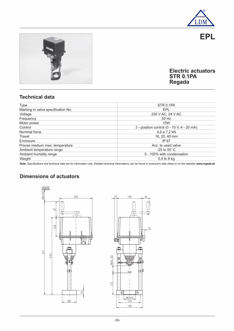
®
-55-
Electric actuatorsSTR 0.1PARegada
EPL
Technical data
3 - position control (0 - 10 V, 4 - 20 mA)
Acc. to used valve-25 to 55 C
5 - 100% with condensation5,4 to 8 kg
o
Marking in valve specification No.VoltageFrequencyMotor powerControlNominal forceTravelEnclosureProces medium max. temperatureAmbient temperature rangeAmbient humidity rangeWeight
TypeEPL
50 Hz15W
STR 0.1PA
230 V AC, 24 V AC
4,6 a 7,2 kN16, 20, 40 mm
IP 67
Dimensions of actuators
Note: www.regada.skSpecifications and technical data are for information only. Detailed technical informations can be found in producer's data sheet or on the webside

®
-56-
Specification of actuator STR 0.1PA
Electric actuator STR 0.1PA 438. X X X X / X X
3x400 V AC3x380 V AC
10 mm/min16 mm/min
4600 25 mm/min32 mm/min
X - X
NG
IJ
I
2
Nom
inal
forc
e [ N
]
Runnin
g s
peed
H
Travel 10-50 mm
40D
40 mm/min10 mm/min16 mm/min25 mm/min
40 mm/min
TU
K
V
Y
7200
Mechanical connection - flange, connecting height 110 mm, thread on con. stem M10x1 or M16x1,5 C
Accessories
Resistance to surroundings- standard
32 mm/min W
10AB LED display (position indicator)
NoneAdjustment of operating stroke to the requied value
57
00F
Additional relays R3, R4, R5 (module DMS3 RE3)Local controls for actuator with DMS3 system and LCD display
24 V DC
24 V DC
Con
trol
F
Con
trol
boar
d
Fee
dbac
k
GH
ON - OFF and inchingDMS3
Modulating ON - OFFand inching
4 - 20 mApasive
0/4 - 20 mA0/2 - 10 V
---
Allowed combination of accessories and codes:A+B=20, A+D=22, A+F=25, A+B+D=52, B+D=29, D+F=40
IP 67IP 67
StandardTropical
-25°C to +55°C-25°C to +55°C
16
230 V AC24 V AC 3Elektrické připojení
0
Terminal board Voltage

-57-
Section A-A
min
. 160
max
.
M20x1.5
Manual control
50
110
±1
56
9 (
57
6**
)
248 (270*)
319
274 (290*)
183 140
22
1
28
30
M 16x1,5-6H
19
M 10x1-6H
®
Electric actuatorsST 1, STR 1Regada
EPI
EPI
50 Hz15W, 20W
3 - position (0 - 10 V, 4 - 20 mA)7,5 and 10 kN
16 - 40 mmIP 65/IP 67
Acc. to used valve-50 to 55°C
5 - 100% with condensation8,5 to 10,9 kg
ST 1, STR 1
230 V AC, 3x400 V AC, 3x380 V AC, 24 V AC, 24 V DCMarking in valve specification No.VoltageFrequencyMotor powerControlNominal forceTravelEnclosureProces medium max. temperatureAmbient temperature rangeAmbient humidity rangeWeight
Type
Technical data
Dimensions of actuators
* Applies to version with electric connection to connector** Applies to actuators with protection code IP 67
Note: www.regada.skSpecifications and technical data are for information only. Detailed technical informations can be found in producer's data sheet or on the webside

®
-58-
Specification of actuator ST 1, STR 1
Electric actuator ST 1, STR 1 491. X X X X / X X
230 V AC
230 V AC
24 V AC
24 V AC
24 V DC
24 V DC
8 mm/min10 mm/min
7500
16 mm/min32 mm/min20 mm/min
Without transmitter A
X - X
3
8
0
256
DEH
Electric connection
0
5
A
C
Runnin
gsp
eed
Moto
rpow
er 1
Tripping torque16 mm20 mm40 mm
Rem
ote
posi
tion tra
nsm
itter
IJ
Capacity
70C
BFKPSQTU
Resistance
W
Terminal board
Voltage
10000
Mechanical connection - flange, connecting height 110 mm, thread on con. stem M10x1 or M16x1,5 K
Accessories
Allowed combination of accessories and codes:A+E=04, A+C=08, E+C=10, A+E+C=12, A+D=16, C+D=17, A+C+D=18
Single
Double6)
V
Electronic- current
0020
AE
Manual control
2 auxiliary position switchesHeater with thermal sensor
3x400 V AC6)
3x400 V AC6)
3x380 V AC6)
3x380 V AC6)
9
7
M
R
51D Space heater
---
---
10
68ACGJ
IP 65IP 67IP 67IP 67IP 65IP 65IP 67IP 67
Resistive feedback
Standard
Standard
Tropical
TropicalUniversal
Resistive feedbackCurrent feedback
Current feedback
Without positioner (ST 0.1)
With positioner (STR 0.1)
Conector
15 W
(23
0; 3
x400
;3x
380
VA
C)
20 W
(24
VA
C/D
C)
Wirin
g
Feedback
Wo. its source
With its source4 - 20 mA
4 - 20 mA
0 - 20 mA
Wo. its source2-wire
2-wire2-wire6)
4 - 20 mAWith its source
3-wire6)
1 x 100 Ω1 x 2000 Ω2 x 100 Ω
2 x 2000 Ω
6) Applies to the version without any positioner8) For the EA version with additional position switches and double transmitter a space heater cannot be specified.
-25°C to +55°C
-25°C to +55°C-50°C to +40°C
-25°C to +55°C
-25°C to +55°C
Resi
stance
to
surr
oundin
gs
Nom
inal
forc
e [ N
]
Notes:
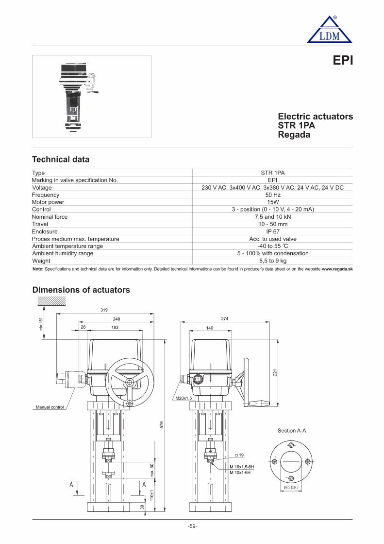
®
-59-
Electric actuatorsSTR 1PARegada
EPI
EPI
50 Hz15W
3 - position (0 - 10 V, 4 - 20 mA)7,5 and 10 kN
10 - 50 mmIP 67
-40 to 55 C
8,5 to 9 kg
STR 1PA
230 V AC, 3x400 V AC, 3x380 V AC, 24 V AC, 24 V DC
o
Section A-A
min
. 160
max
.
M20x1.5
Manual control
50
110
±1
576
248
319
274
183 140
221
28
30
M 16x1,5-6H
19
M 10x1-6H
Marking in valve specification No.VoltageFrequencyMotor powerControlNominal forceTravelEnclosureProces medium max. temperatureAmbient temperature rangeAmbient humidity rangeWeight
Type
Technical data
Dimensions of actuators
Acc. to used valve
5 - 100% with condensation
Note: www.regada.skSpecifications and technical data are for information only. Detailed technical informations can be found in producer's data sheet or on the webside

-60-
Section A-A
®
EPJ
Electric actuatorsST 1-ExRegada
Technical data
Marking in valve specification No.VoltageFrequencyMotor powerControlNominal forceTravelEnclosureProces medium max. temperatureAmbient temperature rangeAmbient humidity rangeWeight
EPJ
50 Hz15 W, 20 W
3 - position control, with positioner 0 - 10 V; (0) 4 - 20 mA7,5 and 10 kN16, 25, 40 mm
IP 67Acc. to used valve
-5 to 55 C05 - 100 % with condensation
Dimensions of actuators
11 - 15 kg
Type ST 1-Ex
230 V AC, 3x400 V AC, 3x380 V AC, 24 V AC, 24 V DC
o
Note: www.regada.skSpecifications and technical data are for information only. Detailed technical informations can be found in producer's data sheet or on the webside

®
-61-
Specification of actuator STR 1PA
Electric actuator STR 1PA 431. X X X X / X X
230 V AC
3x400 V AC24 V AC
3x380 V AC8 mm/min
10 mm/min
7500
16 mm/min32 mm/min20 mm/min
X - X
3
N0
126
I
Electric connection
0
2
Nom
inal
forc
e [ N
]
Runnin
gsp
eed 5
Travel 10-50 mm
60DE
Terminal board
IP 67IP 67IP 67
Voltage
10000
Mechanical connection - flange, connecting height 110 mm, thread on con. stem M10x1 or M16x1,5 K
Accessories
Allowed combination of accessories and codes:A+D=22, A+E=23, A+F=24, D+F=40, E+F=44, A+D+F=63, A+E+F=67
Resistance to surroundings 136
1050
AThe module of additional relay R3, R4, R5 (module DMS3 RE3)
The module of additional relay R1, R2, R3, R4, R5, READY (module DMS3 RE6)
Adjustment of operating stroke to the required valueNone
70F Manual control for actuators with DMS3 a LCD system
24 V DC
Con
trol
Con
trol
boar
d
Fee
dbac
k
GH
DMS3 Modulating 4 - 20 mApasive
0/4 - 20 mA0/2 - 10 V
StandardColdTropical
-25°C to +55°C
-25°C to +55°C-25°C to +55°C
ON - OFFand inching

®
-62-
Specification of actuator ST 1-Ex
230 V AC
8 mm/min16 mm/min
7500 N
Maximal stroke (without transmitter) acc. to mechanicalconnection [mm]. Stroke can be adjusted in range from0 to max. stroke value in actuators without transmitter
10 mm/min20 mm/min
Without transmitter A
J
0
56
DEH
Electric connection 0A
VoltageTerminal board
Nom
inal
forc
e N[
]
Runnin
gsp
eed
Mot
or p
ower 1
50
Tra
vel 16 mm
20 mm40 mm
Rem
ote
posi
tion tra
nsm
itter
Wirin
g
Feedback
Mechanical connection - flange, connecting height 110 mm, thread on con. stem M10x1 or M16x1,5
F1 x 100 Ω
1 x 2000 Ω
S4 - 20 mA
4 - 20 mA
B
V
ResistanceSingle
0 - 20 mA
0 - 20 mA
I4 - 20 mA
UW
4 - 20 mA
4 - 20 mA
Q
With its source 59)
With its source 51)
Without its source
Without its source
Electronic- current
Kapacitní2 - wire
2 -wire
2 - wire
3 - wire 6)
2 - wire 6)
3 - wire 6)
24 V AC
24 V DC
393x400 V AC 6)
232 mm/min
10000 N
740 mm/min
10000 N8600 N5800 N
KP
Double 6) 58)
T
2 x 100 Ω2 x 2000 Ω
6) Applies to version without positioner51)
Notes:
For version with positioner with current feedback only. The output signal from thecapacitive transmitter is not galvanically insulated from the input signal.Valid only for 24 V DC and without additional position switches S5, S6.Active position transmitter for version 24 V DC only after agreement with producer
5 )85 )9
---
---
4 - 20 mA
4 - 20 mA
With its source 59)
411. X - X X X X X
K
Electric actuator ST 1-Ex1
IP 67
IP 67
IP 678BD
M
Resi
stance
to s
urr
oundin
gs
Normal execution (without positioner)
With regulatorCurrent feedback transmitter
Current feedback transmitter
Resistive feedback transmitter
Resistive feedback transmitter
Standard
Standard
Universal
Universal-25°C to +55°C
-25°C to +55°C
-50°C to +40°C
-50°C to +40°C
15 W
(23
0; 3
x400
;3x
380
VA
C)
20 W
(24
VA
C/D
C)

-63-
®
Electric actuatorsST 2, STR 2Regada
EPM
Technical data
EPM
50 Hzsee specification table
3 - position control with positioner 0 - 10 V, (0) 4 - 20 mA16 a 25 kN
40, 80, 100 mmIP 65 / IP 67
Acc. to used valve-50 to 55 C
5 - 100% with condensation
Dimensions of actuators
17 to 21,5 kg
ST 2, STR 2
230 V AC, 3x400 V AC, 3x380 V AC, 24 V AC, 24 V DC
o
Marking in valve specification No.VoltageFrequencyMotor powerControlNominal forceTravelEnclosureProces medium max. temperatureAmbient temperature rangeAmbient humidity rangeWeight
Type
Note: www.regada.skSpecifications and technical data are for information only. Detailed technical informations can be found in producer's data sheet or on the webside
CV 3xx NPS 3" - 6" (connection D) CV 3xx NPS 8" - 16" (connection M)
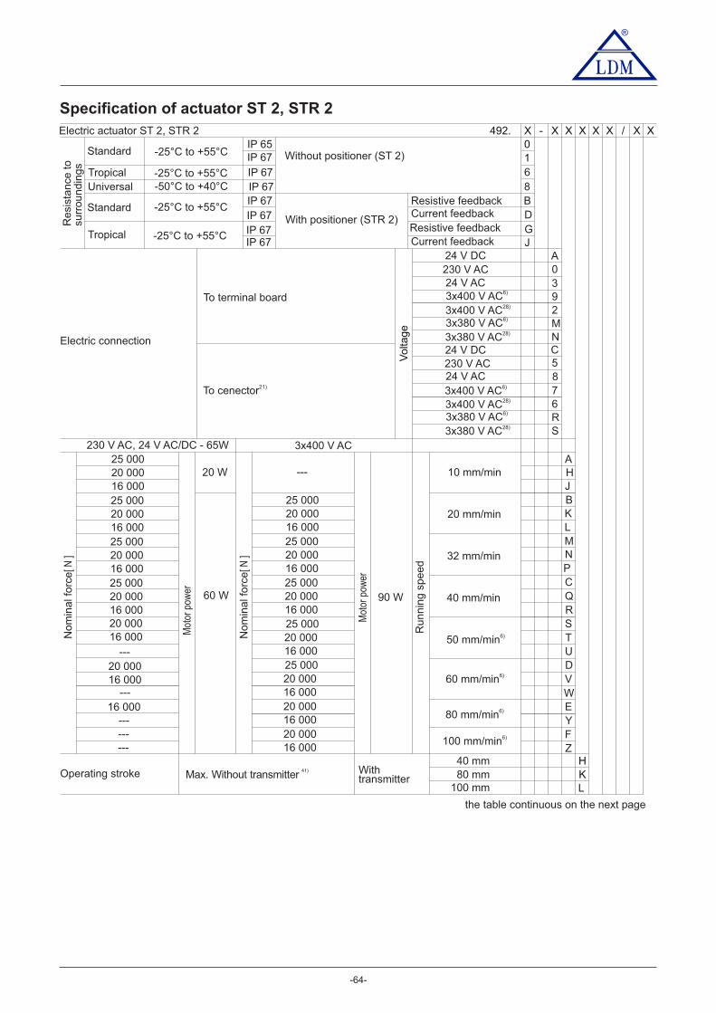
-64-
®
Specification of actuator ST 2, STR 2
Electric actuator ST 2, STR 2 492. X X X X / X X
230 V AC
3x400 V AC28)
25 000
25 000 25 000
25 000 25 000
25 000 25 000
25 000
25 000---
---
---------
20 000
20 000 20 000
20 000 20 000
20 000 20 000
20 000
20 000
20 000
20 000
20 000
20 000
16 000
16 000 16 000
16 000 16 000
16 000 16 000
16 000
16 000
16 000
16 000
16 000
16 000
16 000
X - X
6
S
A
JB
HKL
Electric connection
5
Nom
inal f
orc
e[ N
]
Runnin
g s
peed
Mot
or p
ower
20 W H
Operating stroke
the table continuous on the next page
40 mm80 mm
100 mm
To cenector21)
LM
K
N
R
T
D
W
Y
Z
Resi
stance
to
surr
oundin
gs
10IP 65
IP 67
Q
S
U
V
E
F
7
R
230 V AC
3x400 V AC28) 2
N
0
To terminal board
Volta
ge
324 V AC
3x400 V AC6)
3x400 V AC
10 mm/min
20 mm/min
32 mm/min
40 mm/min
50 mm/min6)
60 mm/min6)
80 mm/min6)
100 mm/min6)
CP
---
Nom
inal f
orc
e[ N
]
Mot
or p
ower
60 W 90 W
230 V AC, 24 V AC/DC - 65W
Max. Without transmitter Withtransmitter
41)
A24 V DC
9
M
3x400 V AC6)
3x380 V AC6)
3x380 V AC28)
3x380 V AC6)
3x380 V AC28)
24 V DC C
24 V AC 8
IP 67IP 67IP 67IP 67IP 67IP 67
68
Resistive feedback
Resistive feedback
Standard
Standard
Tropical
TropicalUniversal
Current feedback
Current feedback
DB
GJ
Without positioner (ST 2)
With positioner (STR 2)
-25°C to +55°C
-25°C to +55°C
-25°C to +55°C
-25°C to +55°C
-50°C to +40°C

®
Specification of actuator ST 2, STR 2
Electric actuator ST 2, STR 2 492. X X X X / X XWithout transmitter A
X - X
Rem
ote
posi
tion tra
nsm
itter
Con
nect
ion
Fee
dbac
k
IJ
CapacityWithout its source
With its source
52G
BFKP
1 x 100 Ω1 x 2000 Ω2 x 100 Ω
2 x 2000 ΩS
T
V
Q
Resistance
4 - 20 mA
0 - 20 mA
Without its source
Without its source
Without its source
2-wire
Sloupky, připojovací výška 126 mm, závit táhla M20x1,5 M
Příslušenství
Single
Double
Electronic- current
With its source
With its source
With its source
2-wire2-wire6)
00
51
A
DNastavení vypínací síly na požadovanou hodnotu
2 přídavné polohové spínače
Topný odpor
51)
W
3-wire6) U
4 - 20 mA
Mechanické připojeníDPříruba, připojovací výška 110 mm, závit táhla M16x1,5
70C20E
Místní ovládáníTopný odpor s tepelným spína emč
Allowed combination of accessories and codes:A+E=04, A+C=08, C+E=10, A+C+E=12, A+D=16, C+D=17, A+C+D=18, A+G=26, E+G=27, C+G=28,D+G=29, A+E+G=30, A+C+G=31, A+D+G=32, C+E+G=33,C+D+G=34, A+D+E+G=35, A+C+D+G=36
28) Version with reverse contacts21) The version with connector not less in -40°C.6) Applies to version without positioner
41) The version without any transmitter can have adjusted its stroke from 0 up to 80 mm51) For a version with a positioner with current feedback only.
-65-

-66-
®
Electric actuatorsSTR 2PARegada
EPM
Technical data
Dimensions of actuators
Marking in valve specification No.VoltageFrequencyMotor powerControlNominal forceTravelEnclosureProces medium max. temperatureAmbient temperature rangeAmbient humidity rangeWeight
TypeEPM
50 Hzsee specification table
3 - position control with positioner 0 - 10 V, (0) 4 - 20 mA16 a 25 kN
40, 80, 100 mmIP 67
Acc. to used valve-40 to 55 C
5 - 100% with condensation17 to 21 kg
STR 2PA
230 V AC, 3 x 400 V AC, 3 x 380 V AC
o
Note: www.regada.skSpecifications and technical data are for information only. Detailed technical informations can be found in producer's data sheet or on the webside
CV 3xx NPS 3" - 6" (connection D) CV 3xx NPS 8" - 16" (connection M)

®
-67-
Specification of actuator STR 2PA
Electric actuator STR 2PA 432. X X X X / X X
20 000
25 000
X - X
A
BL
KL
Electric connection
Nominal force [ N ] Running speed 230 V 3x400 V, 3x380 V
J
Travel20-80 mm20-100 mm
R
R
D
D
C
C
V
V
Z
Z
Z
Z
Columns, connecting height 126 mm, thread on con. Stem M20x1,5 M
Resistance to surroundings 1
Y
Y
Y
Y
230 V AC 0
Spín
ání
ele
ktro
moto
ru
Volta
ge 3x400 V AC
3x400 V AC3x380 V AC
3x380 V AC
2
EN
F
10 mm/min20 mm/min32 mm/min40 mm/min50 mm/min60 mm/min10 mm/min20 mm/min32 mm/min40 mm/min
50 mm/min
60 mm/min
80 mm/min100 mm/min10 mm/min20 mm/min32 mm/min40 mm/min
50 mm/min
60 mm/min
80 mm/min
100 mm/min
16 000
E
E
E
E
W
W
W
Mechanical connectionDF 16 ,5lange, connecting height 110 mm, thread on con. stem M x1
24 V DC
Con
trol
Con
trol
boar
d
Fee
dbac
k
GH
DMS3 Modulating ON - OFFand inching
4 - 20 mApasive
0/4 - 20 mA0/2 - 10 V
50DAccessories
Allowed combination of accessories and codes:A+D=22, A+E=23, A+F=24, D+F=40, E+F=44, A+D+F=63, A+E+F=67
10AAdditional relays R3, R4, R5 (modul DMS3 RE3)Additional relays R1, R2, R3, R4, R5, READY (modul DMS3 RE6)
Adjustment of operating stroke to the required valueNone
67
00
EF Manual control for actuators with DMS3 a LCD system
IP 67IP 67
IP 6736
StandardColdTropical
Prostřednictvím optočlenů
Prostřednictvím reverzních stykačů
Bezkontaktní spínání
-25°C to +55°C
-25°C to +55°C-40°C to +40°C

®
-68-
Electric actuatorsCVLRotork
EQL
Technical data
Marking in valve specification No.
Optional accessories
VoltageExecution
FrequencyControlFeedbackRunning speedFail-safe action timeCharging time of the capacitorsFail-safe functionNominal force
50 Hz
IP 68Acc. to used valve
-30 to 70°C (for low temperature -40 to 60°C)Ex execution -20 to 60°C (for low temperature -40 to 60°C)
optionally
4 - 20 mA4 - 20 mA
2 kN16, 20 mm 16, 20 mm 16, 20, 40 mm 40, 80, 100 mm
4 kN 6,3 kN 16 a 20 kN
Type
Weight
EQL
6,35 mm/smax. 6 s
30 smax. 20 s
100 smax. 20 s
100 smax. 45 s
300 s
2,54 mm/s 2,54 mm/s 2,54 mm/s
CVL-5000 (Ex)
53 kg
CVL-500 (Ex)
16 kg
CVL-1000 (Ex)
24 kg
CVL-1500 (Ex)
24 kg
230V AC, 24V DCLinear electric actuator (optionally with fail-safe function)
Normally open (NO) or Normally closed (NC)
TravelEnclosureProces medium max. temp.Ambient temperature range
Manual override
Note: Specifications and technical data are for information only.Detailed technical informations can be found in producer's data sheet or on the webside www.rotork.com
I/O parameterisationPossibility to set direction to open/close and action on loss of signal. Independent open/close settings for thrust force in range40-100% is available.
Failsafe
Foundation FieldbusHART
Profibus DPPakscan P3ModbusRIRO
2-wire system
Super Capacitors for moving actuator to set positioncommunication protocolnetwork interfacenetwork interface
network interfacecommunication protocol

®
24
9.5
9.8
2"
25
5.0
* minimal space for service
4 x M25 bushing(3/4" NPT optionally)
37
.51
.48
"
80
.03
.15
"
10
.04
"
157.56.20"
ø150
ø65
5.91"
2.56"
167.86.61"
70
.02
.76
"*
30.01.18" *
10.00.39"C OF G
20
.00
.79
"C
OF
G
2 x M5
38.1
1.5
0"
TR
AV
EL
25
.00
.98
"
114
.64
.51
"
28.0ø1.10"
56
.02
.20
"
Dimensions of actuators
STATUS INDICATIONAND BLUETOOTHCOMMUNICATIONS
12
.70
.50
"
grounding
227.58.96"
59.92.36"
53.22.09"
10.00.39"C OF G
43
.11
.69
"
CVL-500 (Ex)
CVL-1000 (Ex), CVL-1500 (Ex)
2 x M6
260.210.25"
10.0.39"C OF G
* minimal space for service
4 x M25 bushing(3/4" NPT optionally)
25
5.0
10
.04
"
ø150
ø65
5.91"
2.56"
TR
AV
EL
grounding20
8.0
8.1
9"
50
.82
.00
"
ø45.01.77"
40
.01
.57
"
99
.03
.90
"
28
9.5
11.4
0"
58
.52
.30
"
80
.03
.15
"
70
.02
.76
"* 30.0
1.18" *
20
.0.7
9"
C O
F G
200.87.91"
1606.29"
111.54.39"
64
.42
.54
" 198.47.81"
-69-
STATUS INDICATIONAND BLUETOOTHCOMMUNICATIONS
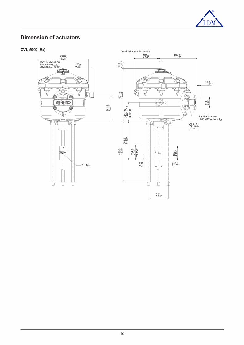
®
Dimension of actuators
CVL-5000 (Ex) * minimal space for service
-70-
40
1.8
46
0.0
15
.82
"1
8.1
1"
20 ±10.79" ±.39C OF G
191.27.53"
293.611.56"
14
3±1
05
.62
"±.
39
C O
F G
10
03
.94
"*
30.01.18" *
80
.03
.15
"
388.015.28"
20
1.3
7.9
3"
235.09.25"
2 x M8
29
6.5
11.6
7"
114
.34
.50
"T
RA
VE
L4
8.0
1.8
9"
10
5.0
4.1
3"
ø55.02.17"
4 x M25 bushing(3/4" NPT optionally)
1505.91"
STATUS INDICATIONAND BLUETOOTHCOMMUNICATIONS

®
Electric actuatorsIQM 10, IQM 12, Ex IQM 10, Ex IQM 12
Rotork
EQA, EQB
Technical data
Marking in valve specification No.
Optional accessories
VoltageExecution
FrequencyControlNominal force
50 Hz
IP 68Acc. to used valve
-30 to 70°C(optionally -40 to 70°C, -50 to 40°C)
-20 to 70°C(optionally -40 to 70°C, -50 to 40°C)
4 - 20 mA10 Nm~5 kN, 15 Nm~7.5 kN, 20 Nm~10 kN, 30 Nm~15 kN, 40 Nm~20 kN
Acc. to valve’s stroke 16, 20, 40 mm
Type
Weight
EQA EQBEx IQM 12IQM 10 IQM 12 Ex IQM 10
3 x 380 or 3 x 400V ACMulti-turn electric actuator (3. generation)
TravelEnclosureProces medium max. temp.Ambient temperature range
-71-
Foundation Fieldbus - network interface
Extra relay contacts S5-S8 independently configurable.Range 24VDC or 120VAC
HART - communication protocol
Analogue control - Folomatic 4–20mA
Profibus DP - network interface
Position transmitter CPT 4-20 mA
Pakscan P3 - network interface / 2-wire system
Interrupter timer (interrupted actuator opening/closing)
Modbus - network interface
Note: Specifications and technical data are for information only.Detailed technical informations can be found in producer's data sheet or on the webside www.rotork.com
31 kg

®
4.6
9"
41
119
-51-
9.0
2"
3.9
8"
ø101
ø229
8.5
4" 11
.14"
9.1
7"
3.4
3"
283
233
ø217
87
* minimal space for service
Dimemsions of actuators
IQM 10, IQM 12, Ex IQM 10, Ex IQM 12
Attachement yoke (2 or 4 columns)
A
B
H
150
110 272
A B
2
No. ofcolumns
140 4204
For valves
CV 3xx NPS ½" - 6"CV 3xx NPS 8" - 16"
~ 8 kg
Weight
~ 15 kg
-72-
36
1.4
2"
30*1.18"
26510.43"
1797.05"
groundingø6.5 (1/4")
ø300
11.81"
165*6.50"
268
10.55"
358
14.09"
230*9.06"
1.6
1"
110.43"

®
Electric actuatorsIQM 20, Ex IQM 20
Rotork
EQD, EQB
Technical data
Optional accessories
50 Hz
IP 68Acc. to used valve
-30 to 70°C(optionally -40 to 70°C, -50 to 40°C)
-20 to 70°C(optionally -40 to 70°C, -50 to 40°C)
4 - 20 mA80 Nm 21,6 kN 100 Nm 27 kN, 1 Nm 32 kN~ , ~ 20 ~
Acc. to valve’s stroke 80, 100 mm
EQA EQBIQM 20
54 kg
Ex IQM 20
3 x 380 V or 3 x 400V ACMulti-turn electric actuator (3. generation)
-73-
Foundation Fieldbus - network interface
Extra relay contacts S5-S8 independently configurable.Range 24VDC or 120VAC
HART - communication protocol
Analogue control - Folomatic 4–20mA
Profibus DP - network interface
Position transmitter CPT 4-20 mA
Pakscan P3 - network interface / 2-wire system
Interrupter timer (interrupted actuator opening/closing)
Modbus - network interface
Note: Specifications and technical data are for information only.Detailed technical informations can be found in producer's data sheet or on the webside www.rotork.com
Marking in valve specification No.
VoltageExecution
FrequencyControlNominal force
Type
Weight
TravelEnclosureProces medium max. temp.Ambient temperature range
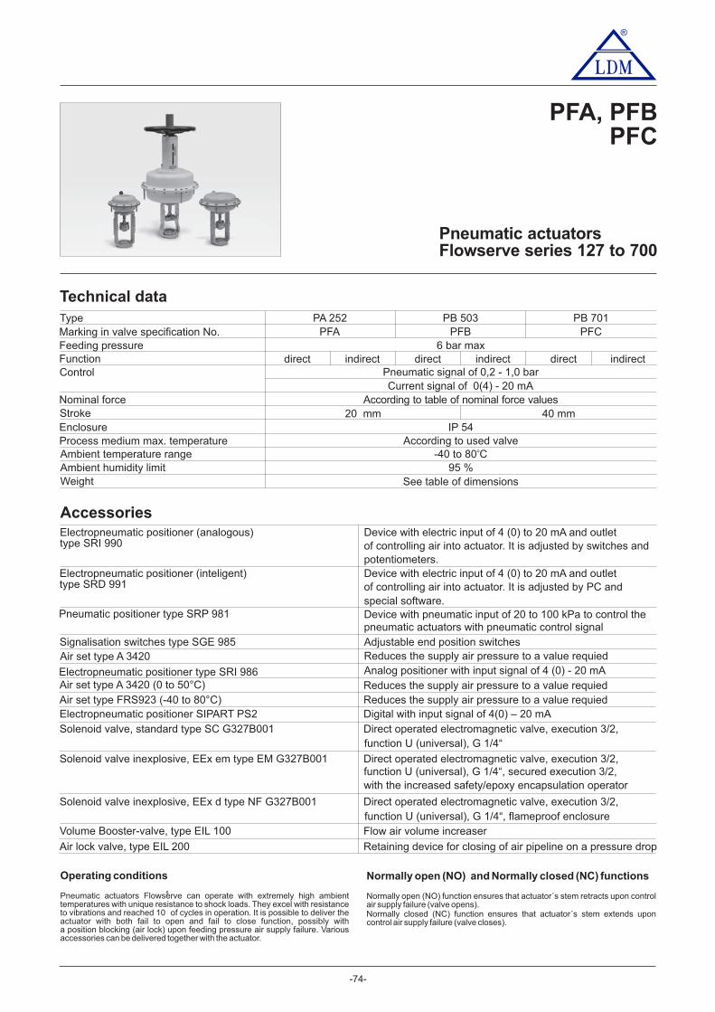
-74-
®
Pneumatic actuatorsFlowserve series 127 to 700
PFA, PFBPFC
Operating conditions
Pneumatic actuators F can operate with extremely high ambientlowservetemperatures with unique resistance to shock loads. They excel with resistanceto vibrations and reached 10 of cycles in operation. It is possible to deliver theactuator with both fail to open and fail to close function, possibly witha position blocking (air lock) upon feeding pressure air supply failure. Variousaccessories can be delivered together with the actuator.
6
Normally open (NO) and Normally closed (NC) functions
Normally open (NO) function ensures that actuator´s stem retracts upon controlair supply failure (valve opens).Normally closed (NC) function ensures that actuator´s stem extends uponcontrol air supply failure (valve closes).
Technical data
Accessories
Feeding pressureFunctionControl
Nominal forceStrokeEnclosureProcess medium max. temperatureAmbient temperature rangeAmbient humidity limitWeight
6 bar max
Pneumatic signal of - 10,2 ,0 bar
IP 54According to used valve
-40 to 80 Co
95 %See table of dimensions
Current signal of 0(4) - 20 mA
indirect
40 mmAccording to table of nominal force values
20 mm
TypeMarking in valve specification No.
PA 252PFA
PB 503PFB
PB 701PFC
direct indirect direct indirectdirect
Electropneumatic positioner (analogous)type SRI 990
Device with electric input of 4 (0) to 20 mA and outletof controlling air into actuator. It is adjusted by switches and
Electropneumatic positioner (inteligent)type SRD 991
Device with electric input of 4 (0) to 20 mA and outletpotentiometers.
of controlling air into actuator. It is adjusted by PC andspecial software.
Pneumatic positioner type SRP 981 Device with pneumatic input of 20 to 100 kPa to control thepneumatic actuators with pneumatic control signal
Signalisation switches type SGE 985 Adjustable end position switchesAir set type A 3420 Reduces air pressure to a value requiedthe supply
Electropneumatic positioner type SRI 986 Analog positioner with input signal of 4 (0) - 20 mAAir set type A 3420 (0 to 50°C) Reduces the supply air pressure to a value requiedAir set type FRS923 (-40 to 80°C) Reduces the supply air pressure to a value requiedElectropneumatic positioner SIPART PS2 Digital 4(0) – 20 mAwith input signal ofSolenoid valve, standard type SC G327B001 Direct operated electromagnetic valve, execution 3/2,
Solenoid valve inexplosive, EEx em type EM G327B001 Direct operated electromagnetic valve, execution 3/2,
Solenoid valve inexplosive, EEx d type NF G327B001 Direct operated electromagnetic valve, execution 3/2,
function U (universal), G 1/4“
function U (universal), G 1/4“, secured execution 3/2,
function U (universal), G 1/4“, flameproof enclosure
Air lock valve, type EIL 200 Retaining device for closing of air pipeline on a pressure drop
Volume Booster-valve, type EIL 100 Flow air volume increaser
with the increased safety/epoxy encapsulation operator
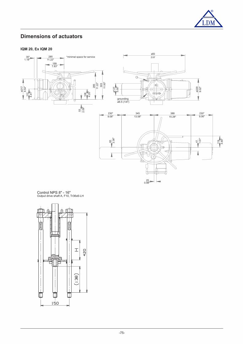
4.6
9"
1.6
1"
2.3
6"
60
41
119
25.59"
9.0
2"
5.0
0"
ø127
ø650
ø22911
.93"
11.2
2"
4.2
5"
4.4
1"8
.54"
ø217 285
108
303
112
2.0
9"
53
Control NPS 8" - 16"Output drive shaft A, F10, Tr36x6-LH
®
*minimal space for service
Dimensions of actuators
IQM 20, Ex IQM 20
-75-
30*1.18"
28511.22"
1997.83"
groundingø6.5 (1/4")
230*9.06"
34513.58"
388
15.28"
230*9.06"
250.98"
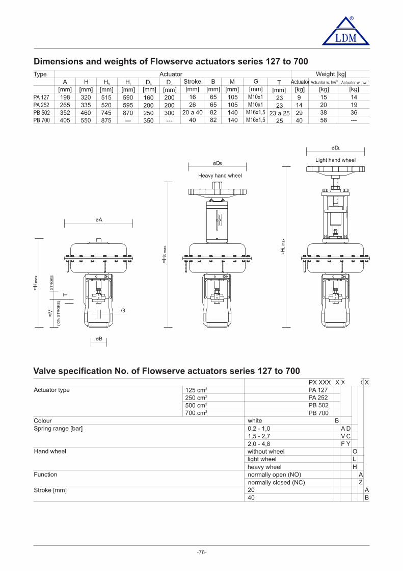
-76-
®
Dimensions and weights of F actuatorslowserve series 127 to 700
Actuator type
Spring range [bar]
Hand wheel
Function
without wheellight wheelheavy wheel
Colour
Stroke [mm]
PX XXXPA 127
2,0 - 4,8
PA 252PB 502
1,5 - 2,70,2 - 1,0
FVA
Z
OL
AH
PB 700B
BA
4020
XXXX
white
X125 cm2
250 cm2
500 cm2
700 cm2
X
DCY
Valve specification No. of Flowserve actuators series 127 to 700
normally closed (NC)normally open (NO)
øDL
≈H
Lm
ax.
≈H
S m
ax.
øA
≈M
( 0%
)S
TR
OK
E
T
øB
≈H
max.
G
øDS
Heavy hand wheel
Light hand wheel
Type
PB 502
H HS HL M TStrokeDA B[mm] [mm] [mm] [mm] [mm][mm] [kg] [kg] [kg][mm][mm] [mm]
D G[mm] [mm]
Actuator Weight [kg]
140 23 a 25460 745 870352 8220 a 40300
Actuator
250
Actuator w. hw Actuator w. hw
29 38 36M16x1,5
PA 252 105 23265 6526200200 14 20 19M10x1335 520 595
LS
PA 127 105 23198 6516200160 9 15 14M10x1320 515 590
PB 700 140 25550 875 ---405 8240---350 40 58 ---M16x1,5
LS
ST
RO
KE

-77-
®®
Pneumatic actuatorsFlowserve series 1502 and 3002
PFD, PFE
Technical data
Accessories
Operating conditions
Pneumatic actuators F can operate with extremely high ambientlowservetemperatures with unique resistance to shock loads. They excel with resistanceto vibrations and reached 10 of cycles in operation. It is possible to deliver theactuator with both fail to open and fail to close function, possibly witha position blocking (air lock) upon feeding pressure air supply failure. Variousaccessories can be delivered together with the actuator.
6
Normally open (NO) and Normally closed (NC) functions
Normally open (NO) function ensures that actuator´s stem retracts upon controlair supply failure (valve opens).Normally closed (NC) function ensures that actuator´s stem extends uponcontrol air supply failure (valve closes).
6,0 bar max
Pneumatic signal 0,2 - 1,0 bar
IP 54According to used valve
-40 to 80°C95 %
124 kg / 174 kg with hand wheel
Current signal of 0(4) - 20 mA
directdirect indirectindirect
According to table of nominal force values80, 100 mm
PO 1502 PO 3002PFD PFE
Feeding pressureFunctionControl
Nominal forceStrokeEnclosureProcess medium max. temperatureAmbient temperature rangeAmbient humidity limitWeight
TypeMarking in valve specification No.
Electropneumatic positioner (analogous)type SRI 990
Device with electric input of 4 (0) to 20 mA and outletof controlling air into actuator. It is adjusted by switches and
Electropneumatic positioner (inteligent)type SRD 991
Device with electric input of 4 (0) to 20 mA and outletpotentiometers.
of controlling air into actuator. It is adjusted by PC andspecial software.
Pneumatic positioner type SRP 981 Device with pneumatic input of 20 to 100 kPa to control thepneumatic actuators with pneumatic control signal
Signalisation switches type SGE 985 Adjustable end position switchesAir set type A 3420 Reduces air pressure to a value requiedthe supply
Electropneumatic positioner type SRI 986 Analog positioner with input signal of 4 (0) - 20 mAAir set type A 3420 (0 to 50°C) Reduces the supply air pressure to a value requiedAir set type FRS923 (-40 to 80°C) Reduces the supply air pressure to a value requiedElectropneumatic positioner SIPART PS2 Digital 4(0) – 20 mAwith input signal ofSolenoid valve, standard type SC G327A001 Direct operated electromagnetic valve, execution 3/2,
Solenoid valve inexplosive, EEx em type EM G327A001 Direct operated electromagnetic valve, execution 3/2,
Solenoid valve inexplosive, EEx d type NF G327A001 Direct operated electromagnetic valve, execution 3/2,
function U (universal), G 1/4“
function U (universal), G 1/4“, secured execution 3/2,
function U (universal), G 1/4“, flameproof enclosure
Air lock valve, type EIL 200 Retaining device for closing of air pipeline on a pressure drop
Volume Booster-valve, type EIL 100 Flow air volume increaser
with the increased safety/epoxy encapsulation operator
240 kg / 290 kg with hand wheel

685
150
ø50011
40
13
50
P. 3
002
P. 3
002
80
0
10
10
P. 1
502
P. 1
502
ø 548
PO 1502 (3002) PB 1502 (3002)
-78-
®
Dimensions and weights of F actuatorslowserve 1502 a 3002(execution without hand wheel)
Valve specification No. of Flowserve actuators series 1502 and 3002
PO XXXXPO 1502
2,0 - 3,5
PO 3002
1,5 - 2,70,4 - 2,0
SCF
ZA
B
D80
XXXX
white
X X
GVF
1500 cm2
3000 cm2
2,6 - 4,2 JA
H = 80 mmPO 1502
2,0 - 4,31,8 - 3,80,9 - 1,9
1,2 - 2,6H = 100 mmPO 3002
LHIJLFAN
without wheelside light wheel S
O
Actuator type
Spring range [bar]
Hand wheel
Function
Colour
Stroke [mm]normally closed (NC)normally open (NO)
®®
H = 100 mmPO 1502

®
-79-
Actuating of valves with hand wheelRV / UV 3x0 and RV 3x2
Hand wheel actuating of valves DN 200 to 400Hand wheel actuating of valves DN 15 - 150
Dimensions of hand wheel actuating:
D6
D5
D6
K
K
M20
M
H
H
110
134
L
L
DN
25324050
mm mm mmmm
6580100125150
317
16
20
MarkingH L mD6D5
mmmm
200
R16
R2840
M
247
339
kg
160
280
350
---
M16x1,5
M10x15
13
65
15
1520
R20
---
275 195 11
Ordering number
S900 0115
S900 0116
S900 0117
S900 0231
(P number)art list
250300400 100 S900 0235
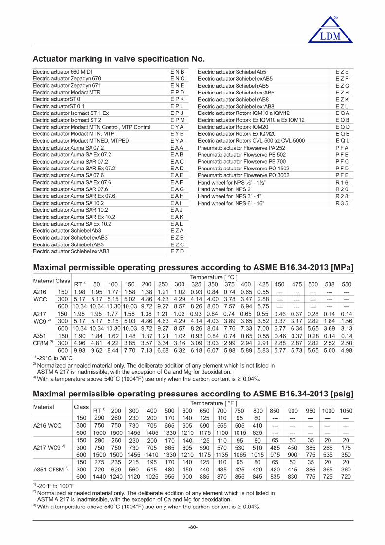
-80-
Maximal permissible operating pressures according to ASME B16.34-2013 [MPa]
Material ClassTemperature [ °C ]
A216
A217
A351
600
300
RT 1) 150 200 250 300 375 400 425 475 500
300150
150
600
600
100 350 450
1) - °C to °C29 38
300150
538 550
---
1.840.14
------
3.69
5.00
---
1.560.14
------
3.13
4.982.520.14
2.500.14
2) Normalized annealed material only. The deliberate addition of any element which is not listed in
50
10.34
5.17
5.171.95
1.95
10.34
9.624.811.84
WCC
CF8M 3)
10.34
5.17
5.171.98
1.98
10.34
9.934.961.90
10.03
5.03
10.30
5.15
5.151.77
1.77
10.30
8.44
5.021.58
1.58
10.03
7.70
9.72
4.86
4.861.38
1.38
9.72
7.13
9.27
4.63
4.631.21
1.21
9.27
6.68
8.57
4.29
4.291.02
1.02
8.57
6.32
8.00
4.03
4.000.84
0.84
8.04
6.07
7.57
3.89
3.780.74
0.74
7.76
5.98
6.94
3.65
3.470.65
0.65
7.33
5.89
5.75
3.52
2.880.55
0.55
7.00
5.83
---
3.370.46
------
6.77
5.77
---
3.170.37
------
6.34
5.73
---
2.820.28
------
5.65
5.653.851.48
4.221.62
3.571.37
3.341.21
3.161.02
3.030.84
2.990.74
2.940.65
2.910.55
2.880.46
2.870.37
2.820.28
325
8.26
4.14
4.140.93
0.93
8.26
6.183.090.93
3) With a temperature above 540°C (1004°F) use only when the carbon content is 0,04%.≥
ASTM A 217 is inadmissible, with the exception of Ca and Mg for deoxidation.
Maximal permissible operating pressures according to ASME B16.34-2013 [psig]
Material ClassTemperature [ °F ]
A216 WCC
A351 CF8M 3)
600
300150
1500
750
RT 1) 300 400 500 600 700 750 800 900
1455
730
950
300150
750290
290
600 1500
600 1440
1500
750
200
750260
260
1500
1240
650 850
730230
230
1455
1120
1405
705
705200
200
1410
1025
1330
665
665170
170
1330
955
1210
605
605140
140
1210
900
1175
590
590125
125
1175
885
1100
570
555110
110
1135
870
1015
530
50595
95
1065
855
825
510
41080
80
1015
845
---
48565
------
975
835
---
45050
------
900
830
---
38535
------
775
775300150
720275
560215
620235
515195
480170
450140
440125
435110
42595
42080
42065
41550
38535
1000 1050
---
26520
------
535
725
---
17520
------
350
72036520
36020
1) -20°F to 100°F2) Normalized annealed material only. The deliberate addition of any element which is not listed in
3) With a temperature above 540°C (1004°F) use only when the carbon content is 0,04%.≥
ASTM A 217 is inadmissible, with the exception of Ca and Mg for deoxidation.
Actuator marking in valve specification No.
®
Electric actuator Schiebel exrAB3 E Z D
Electric actuator Schiebel Ab3 E Z AElectric actuator Schiebel exAB3 E Z BElectric actuator Schiebel rAB3 E Z C
Electric actuator Schiebel Ab5 E Z EElectric actuator Schiebel exAB5 E Z F
Electric actuator Schiebel rAB8 E Z KElectric actuator Schiebel exrAB8 E Z L
Pneumatic actuator Flowserve PA 252 P F APneumatic actuator Flowserve PB 502 P F BPneumatic actuator Flowserve PB 700 P F C
Electric actuator Modact MTR E P D
Electric actuator Zepadyn 670 E N C
Electric actuatorST 0 E P K
Electric actuator Isomact ST 1 Ex E P J
Electric actuator Modact MTN Control, MTP Control E Y AElectric actuator Modact MTN, MTP E Y B
Electric actuator Auma SA 07.2 E AAElectric actuator Auma SA Ex 07.2 E A BElectric actuator Auma SAR 07.2 E A CElectric actuator Auma SAR Ex 07.2 E A D
Electric actuator 660 MIDI E N B
Electric actuatorST 0.1 E P L
Electric actuator Isomact ST 2 E P M
Electric actuator Auma SA 07.6 E A EElectric actuator Auma SA Ex 07.6 E A FElectric actuator Auma SAR 07.6 E A GElectric actuator Auma SAR Ex 07.6 E A H
Electric actuator Schiebel rAB5 E Z GElectric actuator Schiebel exrAB5 E Z H
Electric actuator Auma SA 10.2 E A IElectric actuator Auma SAR 10.2 E A JElectric actuator Auma SAR Ex 10.2 E A KElectric actuator Auma SA Ex 10.2 E A L
Electric actuator Zepadyn 671 E N E
Electric actuator Modact MTNED, MTPED E Y A
Pneumatic actuator Flowserve PO 1502 P F DPneumatic actuator Flowserve PO 3002 P F E
Electric actuator Rotork IQM10 a IQM12 E Q A
Electric actuator Rotork Ex IQM20 E Q EElectric actuator Rotork CVL-500 až CVL-5000 E Q L
Electric actuator Rotork Ex IQM10 a Ex IQM12 E Q BElectric actuator Rotork IQM20 E Q D
Hand wheel for NPS ½” - 1½” R 1 6
Hand wheel for NPS 3" - 4" R 2 8Hand wheel for NPS 6" - 16" R 3 5
Hand wheel for NPS 2" R 2 0

®
-81-
Your partner
LDM, spol. s r.o.Litomyšlská 1378560 02 eská T ebováČ řCzech Republic
tel.: +420 465 502 511fax: +420 465 533 101E-mail: [email protected]://www.ldm.cz
LDM servis, spol. s r.o.Litomyšlská 1378560 02 eská T ebováČ řCzech Republic
tel.: +420 465 502 411-3fax: +420 465 531 010E-mail: [email protected]
LDM, Polska Sp. z o.o.ul. Bednorza 140-384 KatowicePoland
tel.: +48 32 730 56 33fax: +48 32 730 52 33mobile: +48 601 354 999E-mail: [email protected]
LDM Bratislava s.r.o.Mierová 151821 05 BratislavaSlovakia
tel.: +421 2 43415027-8fax: +421 2 43415029E-mail: [email protected]: www.ldm.sk//
LDM OOD- Bulgaria -z. k. Mladost 1bl. 42, floor 12, app. 571784 SofiaBu garil a
tel.: +359 2 9746311fax: +359 2 9746311
: +359 88 925 766mobile 8E-mail: [email protected]
TOO LDM“ ”Lobody 46/2Office No. 4100008 KaragandaKazakhstan
tel.: +7 7212 566 936fax: +7 7212 566 936mobile: +7 701 738 36 79E-mail: [email protected]: .kz//www.ldm
OOO LDM" Promarmatura"Jubilejniy prospekt,dom.6a, of. 601141400 Khimki Moscow RegionRussian Federation
tel.: +7 4957772238fax: +7 4956662212mobile +7 9032254333:E-mail: @inforus ldmvalves.com
LDM Armaturen GmbHWupperweg 21D-51789 LindlarGermany
tel.: +49 2266 440333fax: +49 2266 440372mobile: +49 77 29604691E-mail: [email protected]://www.ldmvalves.com
LDM, spol. s r.o.Office in PraguePodolská 50147 01 Praha 4
tel.: 241087360fax: 241087192E-mail: [email protected]
LDM, spol. s r.o.Office in Ústí nad LabemLadova 2548/38400 11 Ústí nad Labem- Severní Terasa
tel.: 602708257E-mail: [email protected]