
01_SEP674_RET670_Exercise_1_Differential_protection.pdf
34
Transformer protection RET670 Exercise 1 – Differential protection Engineering 1MRG004956
-
Upload
pablo-arancibia -
Category
Documents
-
view
34 -
download
8
Transcript of 01_SEP674_RET670_Exercise_1_Differential_protection.pdf

Transformer protection RET670Exercise 1 – Differential protectionEngineering
1MRG004956


Exercise 1 – Engineering
Transformer protection RET670 Page 11MRG004956
Field Code Changed
CopyrightThis document and parts thereof must not be reproduced or copied withoutwritten permission from ABB, and the contents thereof must not be imparted toa third party, nor used for any unauthorized purpose.
The software or hardware described in this document is furnished under alicense and may be used, copied, or disclosed only in accordance with the termsof such license.
Trademarks
ABB is a registered trademark of ABB Group. All other brand or product namesmentioned in this document may be trademarks or registered trademarks of theirrespective holders.
ABB AB
Substation Automation Products
SE-721 59 Västerås
Sweden
Telephone: +46 (0) 21 34 20 00
Facsimile: +46 (0) 21 14 69 18
www.abb.com/substationautomation
Exercise 1 – Engineering
Page 2 Transformer protection RET6701MRG004956
Field Code Changed
Transformer differential protection engineering
On completion of this exercise you should be able to understand· normal steps in the engineering process of an IED· transformer differential characteristics and main settings

Exercise 1 – Engineering
Transformer protection RET670 Page 31MRG004956
Field Code Changed
Transformer differential protection
This exercise is based on the configuration in figure 1, i.e., a three winding transformer protection.
Figure 1 shows all included functionality in the configuration. Function blocks in black are configured and therest indicate possible additions.
W1
TR PTTR
49 Ith
TCM YLTC
84 ↑↓
TR PTTR
49 Ith
REF PDIF
87N IdN/I
OEX PVPH
24 U/f>
DRP RDRE
Mont.
RET670
YY
22 kV Bus
140 kV Bus
11 kV Bus
IEC61850
ANSI IEC
Functionconfigured
IEC61850
ANSI IEC
Functionnot configured
Transformer Data:80 / 80 / 30 MVA
145±9*1,67% / 22 / 11 kV318 / 2099 / 1574 A
YNd5d11
140kV/110V
500/1
2000/1
300/1
22kV/110V
1500/1W3 W2
CV MMXU
Meter.
C MMXUMeter.
C MMXU
Meter.
C MSQI
Meter.
C MSQI
Meter.
T3W PDIF
87T 3Id/I
CV MMXU
Meter.
Figure 1: A protection application for a three winding transformer in single breaker arrangement

Exercise 1 – Engineering
Page 4 Transformer protection RET6701MRG004956
Field Code Changed
Start PCM600 and open project
PCM600 is the tool to be used to engineer theIED i.e. to do all necessary changes when itcomes to configuration, settings etc.
There is a project prepared to be used in thisexercise. The project is named RET670_Exercise.It is saved in the PCM600 database. The projectcontains all configured data for the IED.
The Project Manager is used to handle projectsand now we will open the project.
When the project has been opened, PCM600 willreturn to the Plant Structure and here you canexpand the structure.
Check the connected IED if version 1p1 or 1p2should be used (use the local HMI).
Below the IED-level there are two levels- IED configuration- Application Configuration
1. Start PCM600
Figure 2: The File Menu
2. Open the Project Manager
Figure 3: Open Project
3. Open Project RET670_1p2_Training_Ex1
Figure 4: The Plant Structure
4. Expand the tree structure by clicking on the plus-sign
Exercise 1 – Engineering
Transformer protection RET670 Page 51MRG004956
Field Code Changed
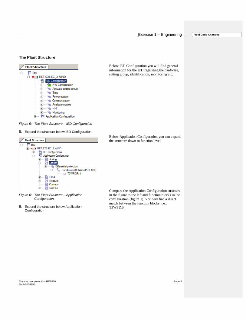
The Plant Structure
Below IED Configuration you will find generalinformation for the IED regarding the hardware,setting group, identification, monitoring etc.
Below Application Configuration you can expandthe structure down to function level.
Compare the Application Configuration structurein the figure to the left and function blocks in theconfiguration (figure 1). You will find a directmatch between the function blocks, i.e.,T3WPDIF.
Figure 5: The Plant Structure – IED Configuration
5. Expand the structure below IED Configuration
Figure 6: The Plant Structure – ApplicationConfiguration
6. Expand the structure below ApplicationConfiguration

Exercise 1 – Engineering
Page 6 Transformer protection RET6701MRG004956
Field Code Changed
IED Properties
Open the Object Properties window.
Here you will find some importantinformation regarding the IED. For instance:IP Address and Terminal version. Thisinformation must match the IED.
IED factory settingsFront port: 10.1.150.3Rear port AB: 192.168.1.10
Product identifiers you will find on the localHMI under
Main menu/Diagnostics/IEDstatus/Product identifiers
Figure 7: IED Properties
7. Open Properties
Figure 8: Parameter Setting
8. Compare included the properties in PCM600 andcorresponding information in the IED (use the localHMI)

Exercise 1 – Engineering
Transformer protection RET670 Page 71MRG004956
Field Code Changed
Hardware Configuration
The transformer protection in the IED hasspecific hardware. Use the HardwareConfiguration tool to check the hardware.
BIM: Binary Input Module
BOM: Binary Output Module
IOM: Combined In- and Output Module
MIM: mA input Module
TRM: Analog input module, 12 currents
TRM: Analog input module, 6 currents, 6voltages
LDCM: Line Data Communication Module(normally not included in a RET 670)
Figure 9: Hardware Configuration
9. Open the hardware configuration
Figure 10: Parameter Setting
10. Compare hardware in PCM600 and in the IED (usethe local HMI and/or indentify the modules from rearview)

Exercise 1 – Engineering
Page 8 Transformer protection RET6701MRG004956
Field Code Changed
License update tool
The License update tool is used tosynchronize a PCM600 IED object withthe physical IED capabilities when itcomes to functions and hardware. Use thetool when you are connected to an IED forthe first time.
Application configuration
You do not have to do any configurationbut it could be useful to start the ACT-tooland get to know the configuration
Parameter setting
The transformer protection is configuredbut the settings are default values. So weneed to do some adjustments to be able touse the transformer protection in ourapplication.
Figure 11: License Update Tool
11. Start License Update Tool and follow the instructions
Figure 121211: Application configuration
12. Application configuration
Figure 131312: Parameter Setting
13. Open the parameter setting

Exercise 1 – Engineering
Transformer protection RET670 Page 91MRG004956
Field Code Changed
Analog inputs
You will find the settings related to the currentand voltage transformers in TRM_12I andTRM_6I_6U.
Settings for winding 1Current transformer rated values, primary andsecondary.
The channel names are defined in Applicationconfiguration (ACT). The names are updated inPST after reading the settings in the IED.
Use information in figure 1 and update thesettings.
The CT secondary is earthed towards thetransformer i.e. to object.
Figure 141413: Parameter settings forcurrent transformers
14. Move to TRM_6I_6U
Figure 151514: TRM current parametersettings for winding 1
15. Set CTStarPoint to ToObject (all three phases)
16. Set CTSec to 1 A (all three phases)
17. Set CTPrim to 500 A (all three phases)

Exercise 1 – Engineering
Page 10 Transformer protection RET6701MRG004956
Field Code Changed
Settings for winding 2Current transformer rated values, primary andsecondary.
The CT secondary is earthed towards thetransformer, i.e., ToObject.
Settings for high voltage sideVoltage transformer rated values, primary andsecondary.
Figure 161615: TRM currentparameter settings for winding 2
18. Set CTStarPoint to ToObject (all three phases)
19. Set CTSec to 1 A (all three phases)
20. Set CTPrim to 2000 A (all three phases)
Figure 171716: TRM parametersettings for voltage transformers, highvoltage
21. Set VTSec to 110 V (all three phases)
22. Set VTPrim to 140 kV (all three phases)

Exercise 1 – Engineering
Transformer protection RET670 Page 111MRG004956
Field Code Changed
Settings for medium voltage sideVoltage transformer rated values, primary andsecondary.
Setting for winding 3Current transformer rated values, primary andsecondary.
The CT secondary is earthed towards the busbar,i.e., FromObject.
Figure 181817: TRM parameter settingsfor voltage transformers, medium voltage
23. Set VTSec to 110 V (all three phases)
24. Set VTPrim to 22 kV (all three phases)
Figure 191918: TRM current parametersettings for winding 3
25. Move to TRM_12I
26. Set CTStarPoint to FromObject (all three phases)
27. Set CTSec to 1 A (all three phases)
28. Set CTPrim to 1500 A (all three phases)

Exercise 1 – Engineering
Page 12 Transformer protection RET6701MRG004956
Field Code Changed
Pre-processor (SMAI) function block settings
The Pre-processor (SMAI) function block is theinterface between the configuration (ACT) and thesignal matrix (SMT). The function-block could beused both for voltage and current measurement. This isnot defined in the configuration.
The selection voltage or current is a setting parameterper SMAI function block.
These settings are very important.
Voltage: Type 1Current: Type 2
Figure 202019: SMAI function block
29. Move to Analog modules in the Plantstructure
Figure 212120: 3PhaseAnalogGroup
30. Move to 3PhaseAnalogGroup
Figure 222221: Analog Modules
31. Check that all SMAI TYPE-settings arecorrect (1: Voltage and 2: Current)

Exercise 1 – Engineering
Transformer protection RET670 Page 131MRG004956
Field Code Changed
Phase reference angle and LED settings
A reference PhaseAngleRef can be defined to facilitateservice values reading (does not influence protectionfunctions). This analog channels phase angle willalways be fixed to zero degree and all other angleinformation will be shown in relation to this analoginput.
Select a voltage input to be used as angle referencechannel. TRM41-Ch7 corresponds to TRM_6I_6U_32Channel 7 (UL1 HV).
The LED indication module comprising 15 LEDs isstandard. Alarm LEDs can be configured in PCM600.
The module must be taken into operation in PST.
Figure 232319: Analog Modules
32. Move to AISBAS:1
Figure 242420: Phase referenceangle
33. Set PhaseAngleRef to TRM41-Ch7
Figure 252521: Analog Modules
34. Move to HMI and LEDGEN
35. Set Operation to On

Exercise 1 – Engineering
Page 14 Transformer protection RET6701MRG004956
Field Code Changed
Disturbance recorder settings, general
Disturbance report is always included in the IED andacquires sampled data of all selected analog input andbinary signals connected to the function block.Maximum 40 analog and 96 binary signals.
Disturbance report functionality is a common namefor several functions:• Event list• Indications• Event recorder• Trip value recorder• Disturbance recorder
The disturbance recorder will affect the yellow andred LEDs on the local HMI.
Yellow:Disturbance recorder have startedRed:A selected binary input has been activated (Tripsignal)
Figure 262622: IED Conf –Disturbance Report
36. Move to Monitoring and DisturbanceReport
Figure 272723: Disturbance recorder– general
37. Set Operation to On

Exercise 1 – Engineering
Transformer protection RET670 Page 151MRG004956
Field Code Changed
Disturbance recorder settings, specific
It’s also necessary to do some settings regarding thebinary and analog inputs.
Binary inputs
The channel names are defined in Applicationconfiguration (ACT). The names are updated in PSTafter reading the settings in the IED.Operation: OnThe signal will start a recordingTriglevel:Start on positive or negative flankIndication:Show (hide) the signal in the indication list (or not)Set LED:Activate the 3rd red LED on the HMI at operation
Figure 282824: Application Conf –Disturbance Report
38. Move to Monitoring and DisturbanceReport
Figure 292925: Disturbance recorder– binary signals
39. Check the configuration and do propersettings per channel
Exercise 1 – Engineering
Page 16 Transformer protection RET6701MRG004956
Field Code Changed
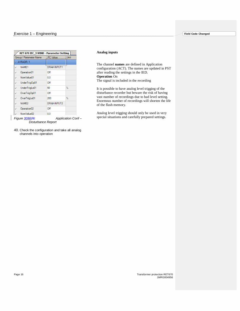
Analog inputs
The channel names are defined in Applicationconfiguration (ACT). The names are updated in PSTafter reading the settings in the IED.Operation OnThe signal is included in the recording
It is possible to have analog level trigging of thedisturbance recorder but beware the risk of havingvast number of recordings due to bad level setting.Enormous number of recordings will shorten the lifeof the flash memory.
Analog level trigging should only be used in veryspecial situations and carefully prepared settings.Figure 303026: Application Conf –
Disturbance Report
40. Check the configuration and take all analogchannels into operation

Exercise 1 – Engineering
Transformer protection RET670 Page 171MRG004956
Field Code Changed
Service value functions
Measurement functions is used for power systemmeasurement, supervision and reporting to the localHMI, monitoring tool within PCM600 or to stationlevel for example, via IEC 61850.
ServiceValues (MMXN), CurrentPhasors (MMXU)and CurrentSequenceComponents (MSQI) areconfigured and should be taken into operation.
We will just transfer measured values to the ControlScreen (single line diagram) thus it’s not necessary toset IBase, UBase and SBase.
Figure 313127: IED Conf –Disturbance Report
41. Move to Measure – Monitoring
Figure 323228: Disturbance recorder– general
42. All Monitoring functions: Set Operation to On

Exercise 1 – Engineering
Page 18 Transformer protection RET6701MRG004956
Field Code Changed
Calculating settings for transformer differential protection
The transformer differential protection is a unit protection. It serves as the main protection of transformers incase of winding failure. The protective zone of a differential protection includes the transformer itself, the bus-work or cables between the current transformers and the power transformer. When bushing current transformersare used for the differential IED, the protective zone does not include the bus-work or cables between the circuitbreaker and the power transformer.
A transformer differential protection compares the current flowing into the transformer with the current leavingthe transformer. A correct analysis of fault conditions by the differential protection must take into considerationchanges due to voltages, currents and phase angle changes caused by protected transformer.Traditional transformer differential protection functions required auxiliary transformers. Differential protectionalgorithm as implemented in the IED compensate for both the turns-ratio and the phase shift internally in thesoftware.
The differential current should theoretically be zero during normal load or external faults if the turn-ratio andthe phase shift are correctly compensated. However, there are several different phenomena other than internalfaults that will cause unwanted and false differential currents. The main reasons for unwanted differentialcurrents are:• Mismatch due to varying tap changer positions• Different characteristics, loads and operating conditions of the current transformers• Zero sequence currents that only flow on one side of the power transformer• Normal magnetizing currents• Magnetizing inrush currents• Over excitation magnetizing currents
The internal / external fault discriminator is a very powerful and reliable supplementary criterion to thetraditional differential protection. It is recommended that this feature shall be always used (enabled) whenprotecting three-phase power transformers. The internal / external fault discriminator detects even minor faults,with a high sensitivity and a high speed, and at the same time discriminates with a high degree of dependabilitybetween internal and external faults.

Exercise 1 – Engineering
Transformer protection RET670 Page 191MRG004956
Field Code Changed
Differential protection settings
The differential protection has two groups ofsettings:
- General settings related to thetransformer data
- Specific settings for the differentialprotection (Setting Group 1-6)
In the first group you will find fundamentalsettings for the differential protection such as,ratings, vector group and clock number.
In the second group you will find specificprotection settings such as, the operatecharacteristic.
Figure 333329: Differential protectionsettings
43. Move to T3WPDIF

Exercise 1 – Engineering
Page 20 Transformer protection RET6701MRG004956
Field Code Changed
Differential protection general settings
Compare the settings and figure 1.
Winding 1 is the phase angle reference (Y) andmagnitude reference.
The transformer is solidly earthed at the 145 kVside. In case of earth-fault in the 145 kV systemresidual current flows from the transformer. Thisresidual current is seen as a differential current evenif there is no internal transformer fault. To preventunwanted trip at external earth-fault there is afunction where the zero sequence current iseliminated from the measured transformer current.This elimination is only needed for winding 1 in thisapplication.
Figure 343430: General setting
44. See Figure 1. Set rated values for W1, W2 andW3.
45. Set connectTypeW1 to WYE
46. Set connectTypeW2 and W3 to Delta
47. Set ClockNumberW2 to 5 (150 deg lag)
48. Set ClockNumberW3 to 11 (30 deg lead)
49. Set ZsCurrSubtrW1 to On
50. Set ZsCurrSubtrW2 and W3 to Off
Exercise 1 – Engineering
Transformer protection RET670 Page 211MRG004956
Field Code Changed
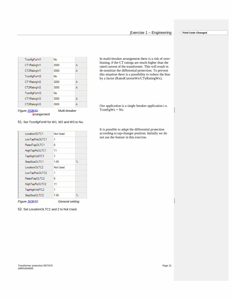
In multi-breaker arrangement there is a risk of over-biasing, if the CT ratings are much higher than therated current of the transformer. This will result inde-sensitize the differential protection. To preventthis situation there is a possibility to reduce the biasby a factor (RatedCurrentWx/CTyRatingWx).
Our application is a single breaker application i.e.TconfigWx = No.
It is possible to adapt the differential protectionaccording to tap-changer position. Initially we donot use the feature in this exercise.
Figure 353531: Multi-breakerarrangement
51. Set TconfigForW for W1, W2 and W3 to No.
Figure 363632: General setting
52. Set LocationOLTC1 and 2 to Not Used.
Exercise 1 – Engineering
Page 22 Transformer protection RET6701MRG004956
Field Code Changed
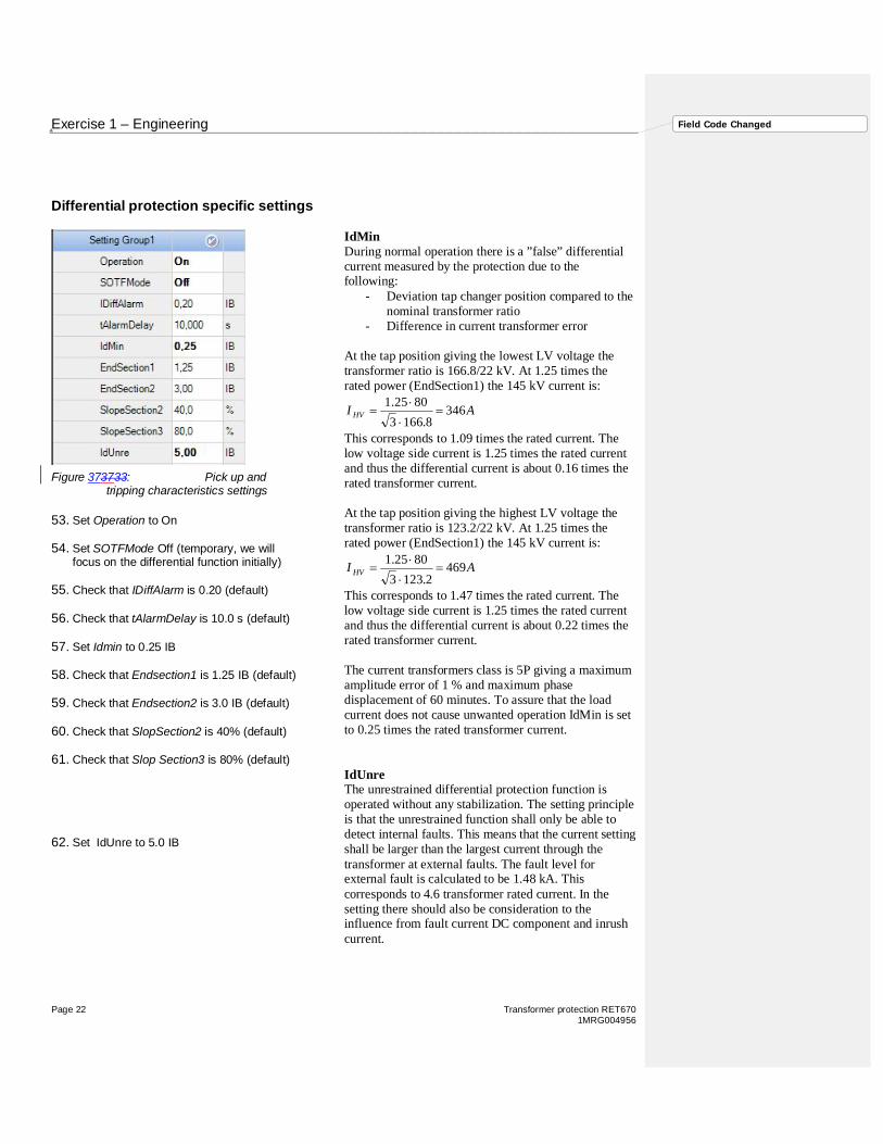
Differential protection specific settings
IdMinDuring normal operation there is a ”false” differentialcurrent measured by the protection due to thefollowing:
- Deviation tap changer position compared to thenominal transformer ratio
- Difference in current transformer error
At the tap position giving the lowest LV voltage thetransformer ratio is 166.8/22 kV. At 1.25 times therated power (EndSection1) the 145 kV current is:
AI HV 3468.1663
8025.1=
×
×=
This corresponds to 1.09 times the rated current. Thelow voltage side current is 1.25 times the rated currentand thus the differential current is about 0.16 times therated transformer current.
At the tap position giving the highest LV voltage thetransformer ratio is 123.2/22 kV. At 1.25 times therated power (EndSection1) the 145 kV current is:
AI HV 4692.1233
8025.1=
×
×=
This corresponds to 1.47 times the rated current. Thelow voltage side current is 1.25 times the rated currentand thus the differential current is about 0.22 times therated transformer current.
The current transformers class is 5P giving a maximumamplitude error of 1 % and maximum phasedisplacement of 60 minutes. To assure that the loadcurrent does not cause unwanted operation IdMin is setto 0.25 times the rated transformer current.
IdUnreThe unrestrained differential protection function isoperated without any stabilization. The setting principleis that the unrestrained function shall only be able todetect internal faults. This means that the current settingshall be larger than the largest current through thetransformer at external faults. The fault level forexternal fault is calculated to be 1.48 kA. Thiscorresponds to 4.6 transformer rated current. In thesetting there should also be consideration to theinfluence from fault current DC component and inrushcurrent.
Figure 373733: Pick up andtripping characteristics settings
53. Set Operation to On
54. Set SOTFMode Off (temporary, we willfocus on the differential function initially)
55. Check that IDiffAlarm is 0.20 (default)
56. Check that tAlarmDelay is 10.0 s (default)
57. Set Idmin to 0.25 IB
58. Check that Endsection1 is 1.25 IB (default)
59. Check that Endsection2 is 3.0 IB (default)
60. Check that SlopSection2 is 40% (default)
61. Check that Slop Section3 is 80% (default)
62. Set IdUnre to 5.0 IB

Exercise 1 – Engineering
Transformer protection RET670 Page 231MRG004956
Field Code Changed
2nd and 5th harmonicThe classical way to avoid tripping due to inrushcurrents or overexcitation is checking the amount of 2nd
and 5th harmonics in relation to the fundamentalfrequency.
IMinNegSeqThe transformer differential protection also hasexternal/internal fault discrimination, based on negativesequence current. The default settings of NegSeqDiffEn,IMinNegSeq and NegSeqROA are recommended.
This feature we will test later.
Open CT detectionIt is possible to detect and avoid tripping due to an opencurrent circuit (one phase out of three). This function isonly active after a certain time (1 min afterenergization) during normal load (10-110% IBias).
This feature we will test later.
Figure 383834: Negativesequence diff protection settings
63. Check that I2/I1Ratio is 15% (default)
64. Check that I5/I1Ratio is 25% (default)
65. Check that CrossBlockEn is On (default)
66. Set NegSeqDiffEn is OFF (temporary, wewill test the feature separately)
67. Check that IMinNegSeq is 0.04 IB (default)
68. Check that NegSeqROA is 60 Deg (default)
Figure 393935: Negativesequence diff protection settings
69. Check that OpenCTEnable is On (default)
70. Check that tOCTAlarmDelay is 3.0 s
71. Check that tOCTResetDelay is 0.25 s
72. Check that tOCTUnrstDelay is 10.0 s

Exercise 1 – Engineering
Page 24 Transformer protection RET6701MRG004956
Field Code Changed
Trip function block settings
A function block for protection tripping is normallyprovided for each circuit breaker involved in thetripping of the fault. It provides the pulse prolongationto ensure a trip pulse of sufficient length.
In this exercise we only use one trip function block.
(Normally we are using the trip matrix function(TMAGGIO) to route trip signals and/or otherlogical output signals to different output contacts onthe IED.)
The signal matrix tool
The graphical signal matrix ofPCM600 allows the user toefficiently connect CTs, VTs,binary input and output signals tothe configuration. The tool can alsobe used for connecting the LEDs onthe IED as well as for connection ofthe GOOSE (IEC 61850) signalsbetween the IEDs.
Figure 404036: Differentialprotection settings
73. Set Operation On
Figure 414137: Differential protection settings
74. Start the Signal Matrix Tool

Exercise 1 – Engineering
Transformer protection RET670 Page 251MRG004956
Field Code Changed
Signal MatrixBinary information
Figure 424238: Binary input mapping
75. Check the mapping binary inputs
Figure 434339: Binary output mapping
76. Check the mapping for binary outputs
Figure 444440: LED mapping
77. Check the mapping for the LEDs

Exercise 1 – Engineering
Page 26 Transformer protection RET6701MRG004956
Field Code Changed
Signal MatrixAnalog Inputs

Exercise 1 – Engineering
Transformer protection RET670 Page 271MRG004956
Field Code Changed
Figure 454541: Analog input mappingwinding 1
78. Check the mapping for winding 1
Figure 464642: Analog input mappingwinding 2
79. Check the mapping for winding 2
Figure 474743: Analog input mappingwinding 3
80. Check the mapping for winding 3

Exercise 1 – Engineering
Page 28 Transformer protection RET6701MRG004956
Field Code Changed
Graphical Display – supplementary exercisePage 1 - Service values
Figure 484844: Graphical Display Editorpresenting service values
81. Use the GDE and create a information screen to bewritten into the IED

Exercise 1 – Engineering
Transformer protection RET670 Page 291MRG004956
Field Code Changed
Write to IED
All data engineered will be read or written. Sometools support separately read/write. Communicationmanagement (CMT), Graphical display editor (GDE)and Parameter setting (PST) can read/write.
Figure 494945: Write to IED
82. Write information to the IED

Exercise 1 – Engineering
Page 30 Transformer protection RET6701MRG004956
Field Code Changed


ABB ABSubstation Automation ProductsSE-721 59 Västerås, SwedenPhone +46 (0) 21 34 20 00Fax +46 (0) 21 14 69 18www.abb.com/substationautomation


