Toyota FJ Cruiser is Discontinued | Find a Used Toyota FJ Cruiser

A750F AUTOMATIC TRANSMISSION – AUTOMATIC TRANSMISSION UNIT AT–193
T
ATRANSMISSIONA750F AUTOMATIC TRANSMISSIONAUTOMATIC TRANSMISSION UNITCOMPONENTS
PARK/NEUTRAL POSITION
SWITCH ASSEMBLY
AUTOMATIC TRANSAXLE BREATHER TUBE
AUTOMATIC
TRANSMISSION
HOUSING
OIL COOLER TUBE UNION
TRANSMISSION CASE
ADAPTER SUB-ASSEMBLY
TRANSMISSION CASE
ADAPTOR OIL SEAL
TRANSMISSION CONTROL
SHAFT LEVER LH
TRANSMISSION WIRE
N*m (kgf*cm, ft*lbf) :Specified torque
Non-reusable part
16 (163, 12)
5.4 (55, 48 in.*lbf)
O-RING
6.9 (70, 61 in.*lbf)
34 (345, 25)
34 (345, 25)
13 (129, 9.4)
WASHER
O-RING
O-RING
LOCK WASHER
5.4 (55, 48 in.*lbf)
5.4 (55, 48 in.*lbf)
34 (345, 25)
5.4 (55, 48 in.*lbf)
34 (345, 25)
57 (581, 42)
x2
x6
x2
29 (296, 21)
TRANSMISSION REVOLUTION SENSOR
TRANSMISSION REVOLUTION SENSOR
C133776E01

AT–194 A750F AUTOMATIC TRANSMISSION – AUTOMATIC TRANSMISSION UNIT
AT
N*m (kgf*cm, ft.*lbf) : Specified torque
O-RING
O-RING
SPACER
PARKING LOCK
PAWL SHAFT
E-RING
7.4 (75, 65 in.*lbf)
SPRING
SPRING
SPRING
SPRING PIN
MANUAL VALVE
LEVER SHAFT
PARKING LOCK PAWL
TORSION SPRING
PARKING LOCK PAWL
B-3 ACCUMULATOR PISTON
BRAKE
DRUM
GASKET
C-1 ACCUMULATOR VALVE
C-2 ACCUMULATOR
PISTON
C-3 ACCUMULATOR PISTON
CHECK BALL BODY
MANUAL VALVE LEVER
SHAFT OIL SEAL
MANUAL VALVE LEVER
SUB-ASSEMBLY
PARKING LOCK
PAWL BRACKET
PARKING LOCK
PAWL SHAFT
TRANSAXLE CASE GASKET
MANUAL VALVE LEVER
SHAFT OIL SEAL
PARKING LOCK ROD
SUB-ASSEMBLY
Non-reusable part
C111190E05

A750F AUTOMATIC TRANSMISSION – AUTOMATIC TRANSMISSION UNIT AT–195
T
ATRANSMISSION OILCLEANER MAGNET
GASKET
AUTOMATIC TRANSMISSION
OIL PAN GASKET
OIL STRAINER
O-RING
x 19
GASKETx 20
x 4
AUTOMATIC TRANSMISSION
OIL PAN SUB-ASSEMBLY
TRANSMISSION VALVE BODY ASSEMBLY
VALVE BODY OIL STRAINER ASSEMBLY
N*m (kgf*cm, ft*lbf) :Specified torque
Non-reusable part
4.4 (45, 39 in.*lbf)
20 (204, 15)28 (285, 21)
10 (100, 7)
11 (112, 8)
C111191E04

AT–196 A750F AUTOMATIC TRANSMISSION – AUTOMATIC TRANSMISSION UNIT
AT
CLUTCH DRUM
THRUST WASHER
NO. 2 CLUTCH DRUM
THRUST WASHER
THRUST NEEDLE
ROLLER BEARING
NO. 1 THRUST
BEARING RACE
O-RING
NO. 2 THRUST BEARING RACE
x10
CLUTCH DRUM AND INPUT
SHAFT ASSEMBLY
NO. 2 1-WAY CLUTCH
ASSEMBLY
NO. 3 BRAKE SNAP RING
OIL PUMP ASSEMBLY
N*m (kgf*cm, ft*lbf) :Specified torque
Non-reusable part
21 (214, 15)
C111194E04

A750F AUTOMATIC TRANSMISSION – AUTOMATIC TRANSMISSION UNIT AT–197
T
ANO. 1 PLANETARY CARRIER
THRUST WASHER
2ND BRAKE PISTON
SNAP RING
NO. 3 BRAKE PLATE
NO. 3 BRAKE FLANGE
2ND BRAKE
PISTON O-RING
1-WAY
CLUTCH
ASSEMBLY
2ND BRAKE CYLINDER
2ND BRAKE PISTON
2ND BRAKE PISTON HOLE SNAP RING
NO. 3 BRAKE DISC
CUSHION PLATE
NO. 3 BRAKE PISTON RETURN
SPRING SUB-ASSEMBLY
Non-reusable partC111193E04

AT–198 A750F AUTOMATIC TRANSMISSION – AUTOMATIC TRANSMISSION UNIT
AT
FRONT PLANETARY
RING GEAR
1-WAY CLUTCH
INNER RACE
NO. 3 THRUST
BEARING RACE
NO. 2 PLANETARY CARRIER
THRUST WASHER
FRONT PLANETARY RING
GEAR FLANGE
NO. 1 BRAKE FLANGE
NO. 1 BRAKE PLATE
FRONT PLANETARY RING
GEAR SHAFT SNAP RING
NO. 1 BRAKE DISC
THRUST NEEDLE ROLLER BEARING
CENTER PLANETARY
RING GEAR
FRONT PLANETARY GEAR ASSEMBLY
C111192E05
A750F AUTOMATIC TRANSMISSION – AUTOMATIC TRANSMISSION UNIT AT–199
T
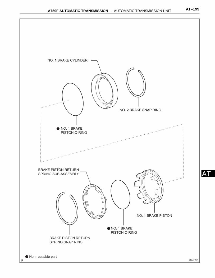
ANO. 1 BRAKE
PISTON O-RING
NO. 1 BRAKE
PISTON O-RING
NO. 1 BRAKE CYLINDER
NO. 2 BRAKE SNAP RING
BRAKE PISTON RETURN
SPRING SNAP RING
NO. 1 BRAKE PISTON
BRAKE PISTON RETURN
SPRING SUB-ASSEMBLY
Non-reusable partC111197E04

AT–200 A750F AUTOMATIC TRANSMISSION – AUTOMATIC TRANSMISSION UNIT
AT
NO. 2 BRAKE
PISTON O-RING
PLANETARY
SUN GEAR
NO. 4 THRUST
BEARING RACE
THRUST NEEDLE
ROLLER BEARING
NO. 2 BRAKE
CYLINDER
NO. 2 BRAKE PISTON
RETURN SPRING
NO. 2 BRAKE PLATE
NO. 2 BRAKE FLANGE
CENTER PLANETARY
GEAR ASSEMBLY
NO. 2 BRAKE DISC
NO. 2 BRAKE PISTON
Non-reusable partC111196E04
A750F AUTOMATIC TRANSMISSION – AUTOMATIC TRANSMISSION UNIT AT–201
T
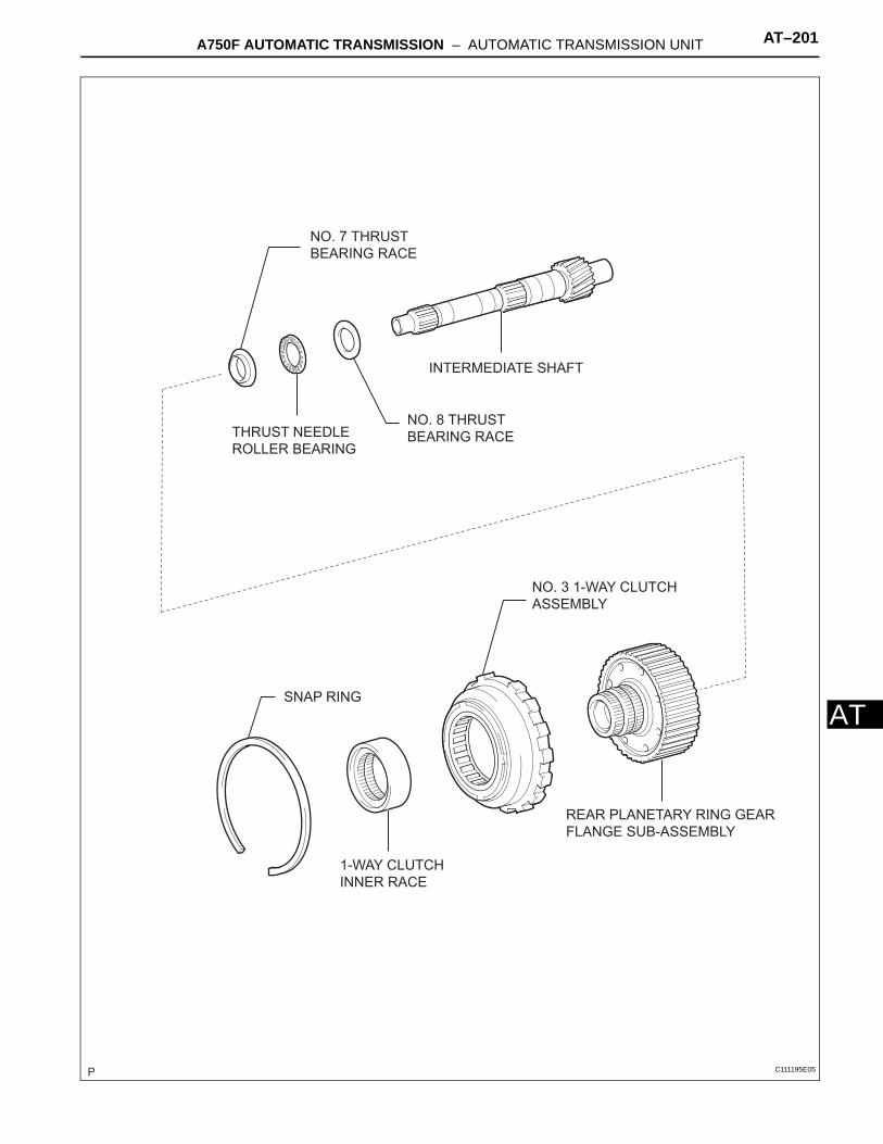
ANO. 8 THRUST
BEARING RACETHRUST NEEDLE
ROLLER BEARING
NO. 7 THRUST
BEARING RACE
REAR PLANETARY RING GEAR
FLANGE SUB-ASSEMBLY
1-WAY CLUTCH
INNER RACE
SNAP RING
INTERMEDIATE SHAFT
NO. 3 1-WAY CLUTCH
ASSEMBLY
C111195E05

AT–202 A750F AUTOMATIC TRANSMISSION – AUTOMATIC TRANSMISSION UNIT
AT
NO. 4 BRAKE DISC
REAR PLANETARY GEAR ASSEMBLY
THRUST NEEDLE
ROLLER BEARING NO. 9 THRUST
BEARING RACE
NO. 4 BRAKE PLATE
NO. 4 BRAKE FLANGE
NO. 4 BRAKE FLANGE
C129562E01

A750F AUTOMATIC TRANSMISSION – AUTOMATIC TRANSMISSION UNIT AT–203
T
ANO. 4 BRAKE PISTON O-RING
BRAKE REACTION
SLEEVE INNER RING
BRAKE REACTION
SLEEVE OUTER
RING
1ST AND
REVERSE BRAKE
PISTON O-RING1ST AND REVERSE
BRAKE RETURN SPRING
SUB-ASSEMBLY
1ST AND REVERSE BRAKE RETURN
SPRING SHAFT SNAP RING
THRUST NEEDLE
ROLLER BEARING
1ST AND REVERSE BRAKE PISTON
BRAKE PLATE STOPPER SPRING
BRAKE REACTION SLEEVE
NO. 4 BRAKE PISTON
Non-reusable partC111198E04

AT–204 A750F AUTOMATIC TRANSMISSION – AUTOMATIC TRANSMISSION UNIT
AT
DISASSEMBLY1. REMOVE TRANSMISSION CONTROL SHAFT LEVER
LH(a) Remove the nut, washer and control shaft lever LH.
2. REMOVE PARK/NEUTRAL POSITION SWITCH ASSEMBLY(a) Using a screwdriver, pry out the lock washer.(b) Remove the nut, lock washer and bolt.(c) Remove the park/neutral position switch.
3. REMOVE OIL COOLER TUBE UNION(a) Remove the 2 oil cooler tube unions.(b) Remove the O-ring from the oil cooler tube union.
4. REMOVE TRANSMISSION REVOLUTION SENSOR(a) Remove the 2 bolts and 2 transmission revolution
sensors.(b) Remove the O-ring from each sensor.
5. REMOVE AUTOMATIC TRANSAXLE BREATHER TUBE(a) Remove the 3 bolts.(b) Remove the breather tube.(c) Remove the O-ring from breather tube.
D027971E01
D027903E01
C111258
D027970E02

A750F AUTOMATIC TRANSMISSION – AUTOMATIC TRANSMISSION UNIT AT–205
T
A6. REMOVE AUTOMATIC TRANSMISSION HOUSING(a) Remove the 10 bolts.(b) Remove the transmission housing.
7. REMOVE TRANSMISSION CASE ADAPTER SUB-ASSEMBLY(a) Remove the 8 bolts and transmission case adapter.
8. REMOVE TRANSMISSION CASE ADAPTOR OIL SEAL(a) Using a screwdriver, pry out the oil seal.
9. FIX AUTOMATIC TRANSMISSION CASE SUB-ASSEMBLY(a) Install the transmission case onto the overhaul
attachment.
10. REMOVE AUTOMATIC TRANSMISSION OIL PAN SUB-ASSEMBLYNOTICE:Do not turn the transmission over as this will contaminate the valve body with foreign matter on the bottom of the pan.(a) Remove the drain plug and the 20 bolts.
11. INSPECT AUTOMATIC TRANSMISSION OIL PAN SUB-ASSEMBLY (See page AT-217)
C111207
C111208
C111209
D027911E01

AT–206 A750F AUTOMATIC TRANSMISSION – AUTOMATIC TRANSMISSION UNIT
AT
12. REMOVE VALVE BODY OIL STRAINER ASSEMBLY(a) Turn over the transmission.(b) Remove the 4 bolts holding the valve body oil
strainer assembly from the valve body.(c) Remove the O-ring form the valve body oil strainer
assembly.
13. REMOVE TRANSMISSION WIRE(a) Remove the ATF temperature sensor.(b) Remove the 2 bolts and 2 clamps.(c) Disconnect the 7 connectors from the shift solenoid
valves.
(d) Remove the bolt from the case.(e) Pull the transmission wire out of the transmission
case.(f) Remove the O-ring from the transmission wire.
14. REMOVE TRANSMISSION VALVE BODY ASSEMBLY(a) Remove the 19 bolts.(b) Remove the valve body assembly.
15. REMOVE TRANSAXLE CASE GASKET(a) Remove the 3 transaxle case gaskets.
D012703E01
Clamp
D012704E01
D027912E01
D012705E01
D027968E03

A750F AUTOMATIC TRANSMISSION – AUTOMATIC TRANSMISSION UNIT AT–207
T
A16. REMOVE BRAKE DRUM GASKET(a) Remove the 3 brake drum gaskets.
17. REMOVE CHECK BALL BODY(a) Remove the check ball body and the spring.
18. REMOVE C-2 ACCUMULATOR PISTON(a) Applying compressed air to the oil hole, remove the
C-2 accumulator piston and spring.(b) Remove the 2 O-rings from the piston.
NOTICE:Be careful as the C-3 and B-3 accumulator pistons may jump out.
19. REMOVE B-3 ACCUMULATOR PISTON(a) Applying compressed air to the oil hole, remove the
B-3 accumulator piston and spring.(b) Remove the 2 O-rings from the piston.
NOTICE:Be careful as the C-3 accumulator piston may jump out.
20. REMOVE C-3 ACCUMULATOR PISTON(a) Applying compressed air to the oil hole, remove the
C-3 accumulator piston and 2 springs.(b) Remove the 2 O-rings from the piston.
D027969E01
Check Ball
Body
Spring
D027914E04
D027915E01
D027915E01
D027916E01

AT–208 A750F AUTOMATIC TRANSMISSION – AUTOMATIC TRANSMISSION UNIT
AT
21. REMOVE C-1 ACCUMULATOR VALVE(a) Remove the C-1 accumulator valve and 2 springs.
22. REMOVE PARKING LOCK PAWL BRACKET(a) Remove the 3 bolts and parking lock pawl bracket.
23. REMOVE PARKING LOCK ROD SUB-ASSEMBLY(a) Disconnect the parking lock rod from the manual
valve lever.
24. REMOVE PARKING LOCK PAWL SHAFT(a) Pull out the parking lock pawl shaft from the front
side, and then remove the lock pawl and spring.(b) Remove the E-ring from the shaft.
25. REMOVE MANUAL VALVE LEVER SUB-ASSEMBLY(a) Using a hammer and screwdriver, cut off the spacer
and remove it from the shaft.
D027917E01
D012708E01
D012709E01
D028846E01
D027918E01

A750F AUTOMATIC TRANSMISSION – AUTOMATIC TRANSMISSION UNIT AT–209
T
A(b) Using a pin punch and hammer, tap out the spring pin.HINT:Slowly drive out the spring pin so that it does not fall into the transmission case.
(c) Pull the manual valve lever shaft out through the case, and remove the manual valve lever.
26. REMOVE MANUAL VALVE LEVER SHAFT OIL SEAL(a) Using a screwdriver, remove the 2 oil seals.
27. REMOVE OIL PUMP ASSEMBLY(a) Remove the 10 bolts holding the oil pump from the
transmission case.
(b) Using SST, remove the oil pump.SST 09350-30020 (09350-07020)
(c) Remove the No. 1 thrust bearing race from the front oil pump.
D027919E01
D027920E01
D027921E01
SST
D027922E02
D028809E01

AT–210 A750F AUTOMATIC TRANSMISSION – AUTOMATIC TRANSMISSION UNIT
AT
28. REMOVE CLUTCH DRUM AND INPUT SHAFT ASSEMBLY(a) Remove the clutch drum and input shaft drum
assembly from the transmission case.
(b) Remove the clutch drum thrust washer, No. 2 thrust bearing race and thrust needle roller bearing.
29. INSPECT NO. 2 1-WAY CLUTCH ASSEMBLY (See page AT-218)
30. REMOVE NO. 2 1-WAY CLUTCH ASSEMBLY(a) Remove the No. 2 1-way clutch assembly and No. 2
clutch drum thrust washer from the clutch drum and input shaft assembly.
31. REMOVE NO. 3 BRAKE SNAP RING(a) Using a screwdriver, remove the No. 3 brake snap
ring from the case.
D027923E01
C133777
D027994E01
D027925E01
A750F AUTOMATIC TRANSMISSION – AUTOMATIC TRANSMISSION UNIT AT–211
T
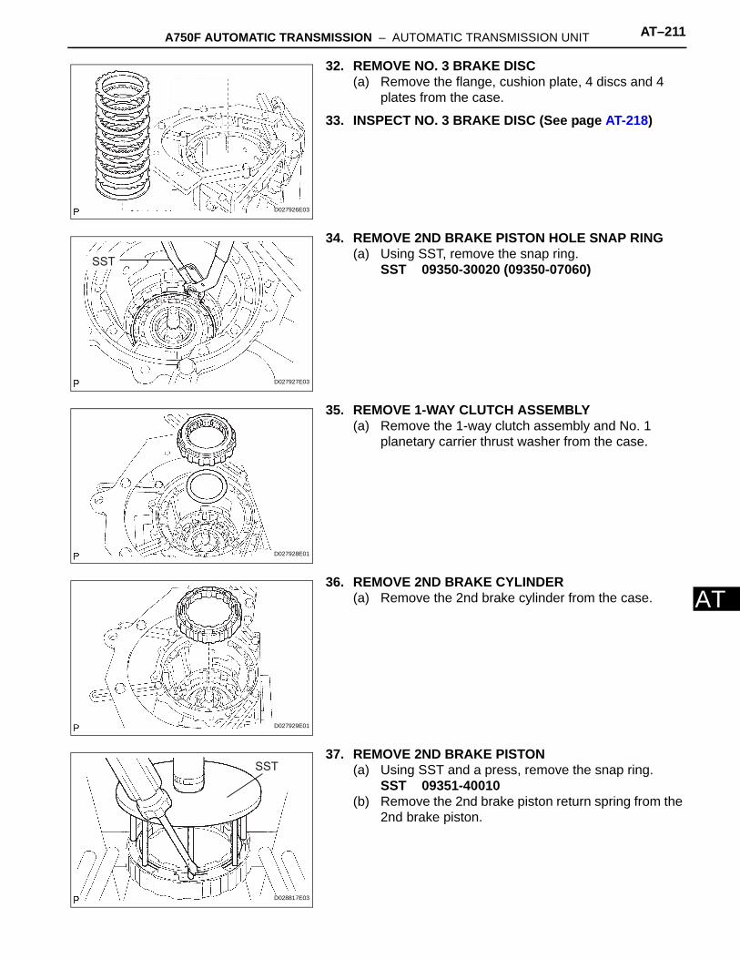
A32. REMOVE NO. 3 BRAKE DISC(a) Remove the flange, cushion plate, 4 discs and 4
plates from the case.
33. INSPECT NO. 3 BRAKE DISC (See page AT-218)
34. REMOVE 2ND BRAKE PISTON HOLE SNAP RING(a) Using SST, remove the snap ring.
SST 09350-30020 (09350-07060)
35. REMOVE 1-WAY CLUTCH ASSEMBLY(a) Remove the 1-way clutch assembly and No. 1
planetary carrier thrust washer from the case.
36. REMOVE 2ND BRAKE CYLINDER(a) Remove the 2nd brake cylinder from the case.
37. REMOVE 2ND BRAKE PISTON(a) Using SST and a press, remove the snap ring.
SST 09351-40010(b) Remove the 2nd brake piston return spring from the
2nd brake piston.
D027926E03
SST
D027927E03
D027928E01
D027929E01
SST
D028817E03

AT–212 A750F AUTOMATIC TRANSMISSION – AUTOMATIC TRANSMISSION UNIT
AT
(c) Hold the 2nd brake piston and apply compressed air (392 kPa, 4.0 kgf/cm2, 57 psi) to the brake cylinder to remove the 2nd brake piston.
(d) Remove the 2 O-rings from the 2nd brake piston.
38. INSPECT NO. 3 BRAKE PISTON RETURN SPRING SUB-ASSEMBLY (See page AT-218)
39. REMOVE FRONT PLANETARY GEAR ASSEMBLY(a) Remove the front planetary gear and 1-way clutch
inner race from the case.
(b) Remove the thrust needle roller bearing, No. 3 thrust bearing race and No. 2 planetary carrier thrust washer from the front planetary gear.
40. INSPECT FRONT PLANETARY GEAR ASSEMBLY (See page AT-218)
41. INSPECT 1-WAY CLUTCH ASSEMBLY (See page AT-219)
42. REMOVE FRONT PLANETARY RING GEAR(a) Remove the front planetary ring gear from the
transmission case.
D028545E01
D028546E03
D027930
D027931
D031542

A750F AUTOMATIC TRANSMISSION – AUTOMATIC TRANSMISSION UNIT AT–213
T
A43. REMOVE CENTER PLANETARY RING GEAR(a) Using a screwdriver, remove the snap ring.
(b) Remove the center planetary ring gear and front planetary ring gear flange from the front planetary ring gear.
44. REMOVE NO. 1 BRAKE DISC(a) Remove the flange, 3 discs and 3 plates from the
case.
45. INSPECT NO. 1 BRAKE DISC (See page AT-219)
46. REMOVE BRAKE PISTON RETURN SPRING SNAP RING(a) Using a screwdriver, remove the brake piston return
spring snap ring from the case.
47. REMOVE BRAKE PISTON RETURN SPRING SUB-ASSEMBLY(a) Remove the brake piston return spring and No. 1
brake piston with the No. 1 brake cylinder from the transmission case.
48. INSPECT BRAKE PISTON RETURN SPRING SUB-ASSEMBLY (See page AT-219)
D028540E01
D028541E01
D027933E03
D027934E01
D027935E01

AT–214 A750F AUTOMATIC TRANSMISSION – AUTOMATIC TRANSMISSION UNIT
AT
49. REMOVE NO. 1 BRAKE PISTON(a) Hold the No. 1 brake piston and apply compressed
air (392 kPa, 4 kgf/cm2, 57 psi) to the transmission case to remove the No. 1 brake piston.HINT:If the piston does not pop out with compressed air, lift the piston out with needle-nose pliers.
(b) Remove the 2 O-rings from the No. 1 brake piston.
50. REMOVE NO. 2 BRAKE DISC(a) Using a screwdriver, remove the snap ring from the
case.
(b) Remove the flange, brake piston return spring, 3 discs and 3 plates from the case.
51. INSPECT NO. 2 BRAKE DISC (See page AT-219)52. INSPECT NO.2 BRAKE PISTON RETURN SPRING
SUB-ASSEMBLY (See page AT-219)
53. REMOVE NO. 2 BRAKE PISTON(a) Hold the No. 2 brake piston and apply compressed
air (392 kPa, 4 kgf/cm2, 57 psi) to the transmission case to remove the No. 2 brake piston.HINT:If the piston does not pop out with compressed air, lift the piston out with needle-nose pliers.
(b) Remove the 2 O-rings from the No. 2 brake piston.
54. REMOVE CENTER PLANETARY GEAR ASSEMBLY(a) Remove the center planetary gear assembly,
planetary sun gear, thrust needle roller bearing and No. 4 thrust bearing race from the case.
55. INSPECT CENTER PLANETARY GEAR ASSEMBLY (See page AT-220)
D027936E01
D027937E01
D027938E03
D027939E01
D031532

A750F AUTOMATIC TRANSMISSION – AUTOMATIC TRANSMISSION UNIT AT–215
T
A56. REMOVE INTERMEDIATE SHAFT(a) Using a screwdriver, remove the snap ring from the
case.
(b) Remove the intermediate shaft with the No. 3 1-way clutch assembly from the case.
57. INSPECT NO. 3 1-WAY CLUTCH ASSEMBLY (See page AT-220)
58. REMOVE NO. 3 1-WAY CLUTCH ASSEMBLY(a) Remove the No. 3 1-way clutch assembly and 1-
way clutch inner race from the intermediate shaft.
59. REMOVE REAR PLANETARY RING GEAR FLANGE SUB-ASSEMBLY(a) Remove the No. 8 thrust bearing race, thrust needle
roller bearing, No. 7 thrust bearing race and rear planetary ring gear flange from the intermediate shaft.
60. INSPECT REAR PLANETARY RING GEAR FLANGE SUB-ASSEMBLY (See page AT-220)
61. INSPECT INTERMEDIATE SHAFT (See page AT-220)
62. REMOVE BRAKE PLATE STOPPER SPRING(a) Remove the brake plate stopper spring from the
case.
D027941E01
D027942E01
D027964E01
No. 7 Thrust
Bearing Race
No. 8 Thrust Bearing Race
Thrust Needle Roller Bearing
D027965E05
D027943E01

AT–216 A750F AUTOMATIC TRANSMISSION – AUTOMATIC TRANSMISSION UNIT
AT
63. REMOVE NO. 4 BRAKE DISC(a) Remove the 7 plates, 8 discs and 2 flanges from the
case.
64. INSPECT NO. 4 BRAKE DISC (See page AT-221)
65. REMOVE REAR PLANETARY GEAR ASSEMBLY(a) Remove the rear planetary gear assembly from the
case.
(b) Remove the No. 9 thrust bearing race and thrust needle roller bearing from the rear planetary gear assembly.
(c) Remove the thrust needle roller bearing from the case.
66. INSPECT REAR PLANETARY GEAR ASSEMBLY (See page AT-221)
D027944E04
D027945E01
Thrust Needle
Roller Bearing
Race
D027946E03
D027947E01

A750F AUTOMATIC TRANSMISSION – AUTOMATIC TRANSMISSION UNIT AT–217
T
A67. REMOVE 1ST AND REVERSE BRAKE RETURN SPRING SUB-ASSEMBLY(a) Place SST on the spring retainer and compress the
brake return spring.SST 09350-30020 (09350-07050)
(b) Using SST, remove the snap ring and brake return spring.SST 09350-30020 (09350-07070)
68. INSPECT 1ST AND REVERSE BRAKE RETURN SPRING SUB-ASSEMBLY (See page AT-222)
69. REMOVE 1ST AND REVERSE BRAKE PISTON(a) Hold the 1st and reverse brake piston and apply
compressed air (392 kPa, 4 kgf/cm2, 57 psi) to the transmission case to remove the No. 2 brake piston.HINT:If the piston does not pop out with compressed air, lift the piston out with needle-nose pliers.
(b) Remove the O-ring from the 1st and reverse brake piston.
70. REMOVE BRAKE REACTION SLEEVE(a) Using SST, remove the reaction sleeve.
SST 09350-30020 (09350-07080)(b) Remove the O-ring from the reaction sleeve.
71. REMOVE NO. 4 BRAKE PISTON(a) Using SST, remove the No. 4 brake piston.
SST 09350-30020 (09350-07090)(b) Remove the 2 O-rings from the No. 4 piston.
INSPECTION1. INSPECT AUTOMATIC TRANSMISSION OIL PAN
SUB-ASSEMBLY(a) Remove the magnets, and use them to collect steel
particles.(b) Carefully look at the foreign matter and particles in
the pan and on the magnets to anticipate the type of wear you will find in the transmission.• Steel (magnetic): bearing, gear and clutch plate
wear• Brass (non-magnetic): bushing wear
Snap Ring
SST
D028083E01
D027948E01
SST
D028079E04
SST
D001240E03
D001124E01

AT–218 A750F AUTOMATIC TRANSMISSION – AUTOMATIC TRANSMISSION UNIT
AT
2. INSPECT NO. 2 1-WAY CLUTCH ASSEMBLY(a) Hold the reverse clutch hub and turn the No. 2 1-
way clutch assembly.(b) Check that the No. 2 1-way clutch assembly turns
freely clockwise and locks when turned counterclockwise.
3. INSPECT NO. 3 BRAKE DISC(a) Replace all discs if one of the following problems is
present: 1) a disc, plate or flange is worn or burnt, 2) the lining of a disc is peeled off or discolored, or 3) grooves or printed numbers have even slight damage.NOTICE:Before assembling new discs, soak them in ATF for at least 15 minutes.
4. INSPECT NO. 3 BRAKE PISTON RETURN SPRING SUB-ASSEMBLY(a) Using vernier calipers, measure the free length of
the spring together with the spring seat.Standard free length:
15.72 mm (0.619 in.)
5. INSPECT FRONT PLANETARY GEAR ASSEMBLY(a) Using a feeler gauge, measure the front planetary
pinion gear thrust clearance.Standard clearance:
0.2 to 0.60 mm (0.008 to 0.024 in.)Maximum clearance:
0.65 mm (0.026 in.)If the clearance is greater than the maximum, replace the front planetary gear assembly.
(b) Using a dial indicator, measure the inside diameter of the front planetary gear bushing.Maximum inside diameter:
57.48 mm (2.263 in.)If the inside diameter is greater than the maximum, replace the front planetary gear.
D027993E01
D001216E01
D029828E01
D028544E01
D028543E01
A750F AUTOMATIC TRANSMISSION – AUTOMATIC TRANSMISSION UNIT AT–219
T
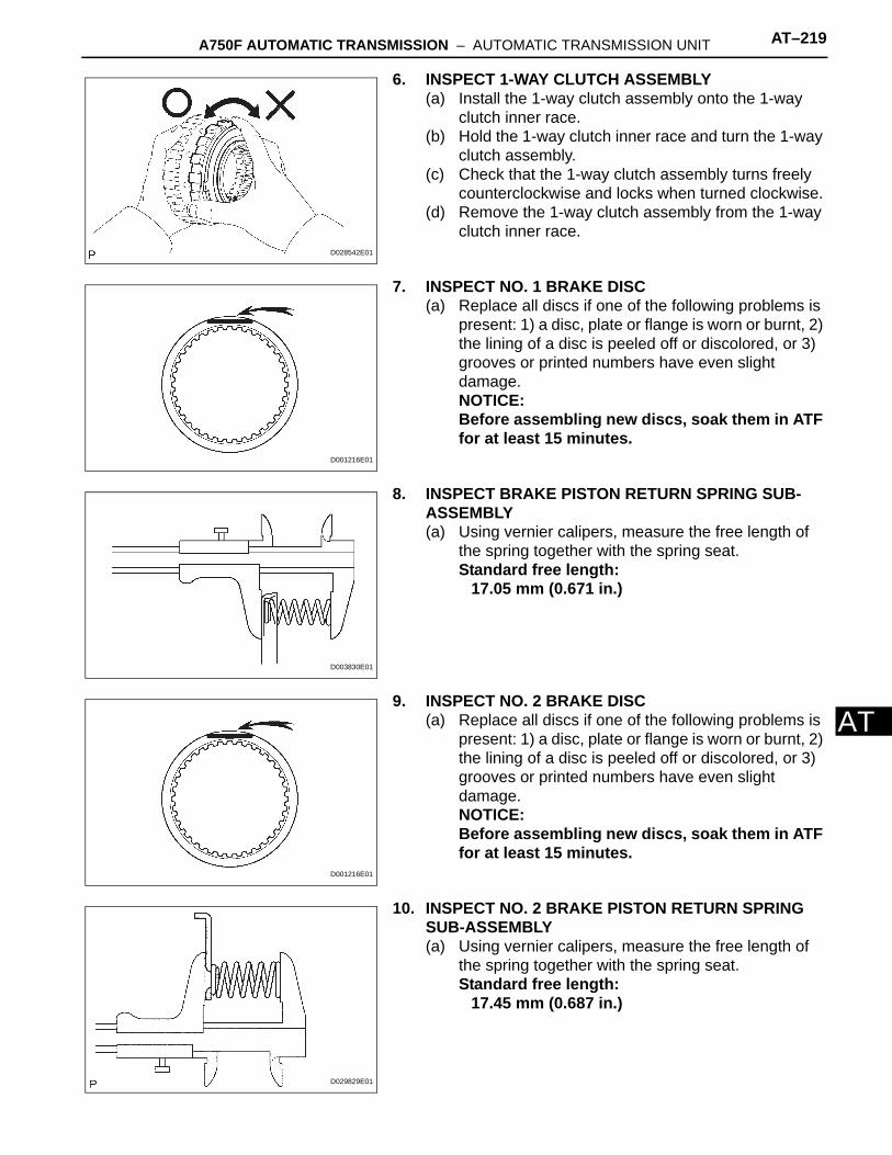
A6. INSPECT 1-WAY CLUTCH ASSEMBLY(a) Install the 1-way clutch assembly onto the 1-way
clutch inner race.(b) Hold the 1-way clutch inner race and turn the 1-way
clutch assembly.(c) Check that the 1-way clutch assembly turns freely
counterclockwise and locks when turned clockwise.(d) Remove the 1-way clutch assembly from the 1-way
clutch inner race.
7. INSPECT NO. 1 BRAKE DISC(a) Replace all discs if one of the following problems is
present: 1) a disc, plate or flange is worn or burnt, 2) the lining of a disc is peeled off or discolored, or 3) grooves or printed numbers have even slight damage.NOTICE:Before assembling new discs, soak them in ATF for at least 15 minutes.
8. INSPECT BRAKE PISTON RETURN SPRING SUB-ASSEMBLY(a) Using vernier calipers, measure the free length of
the spring together with the spring seat.Standard free length:
17.05 mm (0.671 in.)
9. INSPECT NO. 2 BRAKE DISC(a) Replace all discs if one of the following problems is
present: 1) a disc, plate or flange is worn or burnt, 2) the lining of a disc is peeled off or discolored, or 3) grooves or printed numbers have even slight damage.NOTICE:Before assembling new discs, soak them in ATF for at least 15 minutes.
10. INSPECT NO. 2 BRAKE PISTON RETURN SPRING SUB-ASSEMBLY(a) Using vernier calipers, measure the free length of
the spring together with the spring seat.Standard free length:
17.45 mm (0.687 in.)
D028542E01
D001216E01
D003830E01
D001216E01
D029829E01

AT–220 A750F AUTOMATIC TRANSMISSION – AUTOMATIC TRANSMISSION UNIT
AT
11. INSPECT CENTER PLANETARY GEAR ASSEMBLY(a) Using a feeler gauge, measure the center planetary
gear pinion thrust clearance.Standard clearance:
0.12 to 0.68 mm (0.005 to 0.027 in.)Maximum clearance:
0.73 mm (0.029 in.)If the clearance is greater than the maximum, replace the center planetary gear assembly.
12. INSPECT NO. 3 1-WAY CLUTCH ASSEMBLY(a) Hold the rear planetary ring gear flange sub
assembly and turn the 1-way clutch assembly.(b) Check that the 1-way clutch assembly turns freely
counterclockwise and locks when turned clockwise.
13. INSPECT REAR PLANETARY RING GEAR FLANGE SUB-ASSEMBLY(a) Using a dial indicator, measure the inside diameter
of the rear planetary ring gear bushing.Maximum inside diameter:
32.18 mm (1.2667 in.)If the inside diameter is greater than the maximum, replace the rear planetary ring gear.
14. INSPECT INTERMEDIATE SHAFT(a) Using a dial indicator, check the intermediate shaft
runout.Maximum runout:
0.08 mm (0.003 in.)NOTICE:If the bend exceeds the specification, replace the intermediate shaft with a new one.
D028533E01
D028532E01
D028531E01
D028529E01

A750F AUTOMATIC TRANSMISSION – AUTOMATIC TRANSMISSION UNIT AT–221
T
A(b) Using a micrometer, check the outer diameter of the intermediate shaft positions shown in the diagram.Standard diameter:
A:25.962 to 25.975 mm (1.022 to 1.023 in.)
B:25.962 to 25.975 mm (1.022 to 1.023 in.)
C:32.062 to 32.075 mm (1.262 to 1.263 in.)
D:32.062 to 32.075 mm (1.262 to 1.263 in.)
Minimum diameter:A:
25.912 mm (1.020 in.)B:
25.912 mm (1.020in.)C:
32.012 mm (1.260 in.)D:
32.012 mm (1.260 in.)NOTICE:If the outer diameter is outside the standard, replace the intermediate shaft with a new one.
15. INSPECT NO. 4 BRAKE DISC(a) Replace all discs if one of the following problems is
present: 1) a disc, plate or flange is worn or burnt, 2) the lining of a disc is peeled off or discolored, or 3) grooves or printed numbers have even slight damage.NOTICE:Before assembling new discs, soak them in ATF for at least 15 minutes.
16. INSPECT REAR PLANETARY GEAR ASSEMBLY(a) Using a feeler gauge, measure the rear planetary
gear pinion thrust clearance.Standard clearance:
0.2 to 0.6 mm (0.008 to 0.024 in.)Maximum clearance:
0.65 mm (0.026 in.)If the clearance is greater than the maximum, replace the planetary gear assembly.
A B C D
D028530E02
D001216E01
D028527E01

AT–222 A750F AUTOMATIC TRANSMISSION – AUTOMATIC TRANSMISSION UNIT
AT
(b) Using a dial indicator, measure the inside diameter of the rear planetary gear bushing.Maximum inside diameter:
20.075 mm (0.7904 in.)If the inside diameter is greater than the maximum, replace the rear planetary gear assembly.
17. INSPECT 1ST AND REVERSE BRAKE RETURN SPRING SUB-ASSEMBLY(a) Using vernier calipers, measure the free length of
the spring together with the spring seat.Standard free length:
23.74 mm (0.9347 in.)
18. INSPECT PACK CLEARANCE OF FIRST AND REVERSE BRAKE(a) Make sure the 1st and reverse brake pistons move
smoothly when applying and releasing the compressed air into the transmission case.
19. INSPECT NO. 1 PISTON STROKE OF BRAKE PISTON(a) Make sure the No. 1 brake piston moves smoothly
when applying and releasing the compressed air into the transmission case.
D028528E01
D029830E01
D027966E01
D028814E01

A750F AUTOMATIC TRANSMISSION – AUTOMATIC TRANSMISSION UNIT AT–223
T
A20. INSPECT INDIVIDUAL PISTON OPERATION INSPECTION(a) Check the operating sound while applying
compressed air into the oil holes indicated in the illustration.HINT:When inspecting the O/D direct clutch, use the C3 accumulator piston holes indicated in the illustration.If there is no sound, disassemble and check the installation condition of the parts.(1) No. 2 clutch (C2)(2) No. 3 clutch (C3)(3) No. 1clutch (C1)(4) No. 3 brake (B3)(5) No. 1 brake (B1)(6) No. 2 brake (B2)(7) No. 4 brake (B4)
C2 C1
C3
B3
B1
B2
B4
(OUT)B4
(IN)
D028547E02


![FJ CRUISER - Auto-Brochures.com Cruiser/Toyota_US FJCruiz… · Stability Control (VSC) [1] + Traction Control ... Multi-information display floating ball type ... FJ Cruiser 4x2](https://static.fdocuments.us/doc/165x107/5ad0339b7f8b9a71028d9a34/fj-cruiser-auto-cruisertoyotaus-fjcruizstability-control-vsc-1-traction.jpg)