
01 Front Cover - Alamo Industrial€¦ · © 2004 Alamo Group Inc. ALAMO INDUSTRIAL 1502 E. Walnut...
90
© 2004 Alamo Group Inc. ALAMO INDUSTRIAL 1502 E. Walnut Seguin, Texas 78155 210-379-1480 Assembly Instruction Manual Manual Published 09-04 P/N 02981763 Tractors equipped with additional options, special equipment, tractor manufacturer modi- fications, new tractor models, or Customer alterations may prevent this Mount Kit from being properly mounted to the tractor. Alamo Group is not responsible for modifications to the MountKit to accommodate these differences. VERSA FLAIL Case - IH MXU 100 / 110 (Cab / 4 Wheel Drive Tractor) VERSA MOWER
Transcript of 01 Front Cover - Alamo Industrial€¦ · © 2004 Alamo Group Inc. ALAMO INDUSTRIAL 1502 E. Walnut...
© 2004 Alamo Group Inc.
ALAMO INDUSTRIAL1502 E. WalnutSeguin, Texas 78155210-379-1480
Assembly Instruction Manual
Manual Published 09-04P/N 02981763
Tractors equipped with additional options, special equipment, tractor manufacturer modi-fications, new tractor models, or Customer alterations may prevent this Mount Kit frombeing properly mounted to the tractor. Alamo Group is not responsible for modifications tothe MountKit to accommodate these differences.
VERSA FLAIL
Case - IH MXU 100 / 110(Cab / 4 Wheel Drive Tractor)
VERSA MOWER


© 2004 Alamo Group Inc.
NOTES
© 2004 Alamo Group Inc. 0- 1Versa Mower (Case - IH MXU 100 / 110 Asy. Man.) 09/04
INTRODUCTION
ABOUT THIS MANUAL:The intent of this publication to provide the competent technician with the information necessary
to perform the CORRECT Assembly to the Alamo Industrial Product. This will, in turn provide forcomplete customer satisfaction
It is hoped that the information contained in this and other Manuals will provide enough detail toeliminate the need for contact of the Alamo Industrial Technical Service Dept. However, it should beunderstood that many instances may arrive where correspondence with the Manufacturer is neces-sary.
CONTACTING MANUFACTURER: (Please help us Help You! Before You Call! )Alamo Industrial Service Staff Members are dedicated to helping you solve your problem, or
your customer’s service problem as quickly and efficiently as possible. Unfortunately, we receiveentirely to many calls with only a minimum amount of information. In some cases, the correspondenthas never gone out to look at the equipment and merely calls inquiring of the problems described to himby the operator or customer.
Most calls received by Alamo Industrial Service can be classified into approx. 6 general categories.1. Hydraulic or Mechanical Trouble Shooting.2. Request for Technical Information or Specifications.3. Mounting or Fitting Problem.4. Special Service Problem.5. Equipment Application Problems.6. Tractor Problem Inquiries.
HOW YOU CAN HELP:Make sure the call is necessary! Most of the calls received may not be necessary if the Dealer
Service Technician would do the following.
1. Check the Service Information at your Dealership provided by Alamo Industrial, Thiswould include, Service Bulletins, Information Bulletins, Parts Manuals, Operators Manuals, AssemblyManual or Service Manual, many of these are available via the Alamo Industrial Internet site (www.Alamo-Industrial.Com). Attempt to diagnose or repair problem before calling.
2. If a call to Alamo Industrial is needed, Certain Information should be available and readyfor the Alamo Industrial Service Staff. Such information as, Machine Model, Serial Number, Your DealerName, Your Account Number and Any other information that will be useful. This information is vital forthe development of a prompt and correct solution to the problem. This will also help to develop adatabase of problems and related solutions, which will expedite a solution to future problems of a similarnature.
3. The technician may be asked to provide detailed information about the problemincluding the results of any required trouble shooting techniques. If the information is not available, Thetechnician may be asked to get the information and call back. Most recommendations for repairs willbe based on the procedures listed in the Service Manual / Trouble Shooting Guide and Informationprovided by customer.
CONTACT ALAMO INDUSTRIAL:Alamo Industrial, 1502 E. Walnut St. Seguin TX. 78155, Technical Service Dept. PH: 830-379-1480
© 2004 Alamo Group Inc. 0- 2Versa Flail (Case - IH MXU 100 / 110 Asy. Man.) 09/04
INDEX - VERSA MOWERITEM PAGE NO.
INDEX VERSA MOWERIntroduction (Index Section) .................................................................... 0-1Index........................................................................................................ 0-2 to 0-3
SECTION 1Pre-Delivery Inspection Checklist............................................................1-1 to 1-4
SECTION 2General Information................................................................................. 2-1 to 2-6Assembly Area Preparation..................................................................... 2-2 to 2-3Tools Required and/or Recommended................................................... 2-3Recommended Hose End Torque Specifications................................... 2-4Recommended Bolt Torque Specifications.............................................2-4Warning, Danger And Caution Information..............................................2-5
SECTION 3Mainframe Installation.............................................................................. 3-1 to 3-10Mainframe Component Identification....................................................... 3-2Remove Tractor Components from Tractor........................................... 3-3Install Mounting Brackets to tractor......................................................... 3-3Fit Versa Frame to Mounting Brackets.................................................... 3-4Install Rear Axle Stabilizer Bracket......................................................... 3-4Pre-Fit Hydraulic Tank & Install Tank Mounting Lugs............................. 3-5Install Frame Step to Versa Frame......................................................... 3-5Welding mounts to Versa Frame............................................................ 3-6Mount the Hydraulic Tank....................................................................... 3-7Install Extension Arm Frame.................................................................. 3-8Install Cutter Valve and Cylinder Control Valve...................................... 3-9Connect Mower Motor Hoses.................................................................. 3-10
SECTION 4Pump, Driveshaft, Cylinder Control Valve & Cutter Valve Connections..4-1 to 4-12Prepare Tractor Front Bolster................................................................. 4-2Install Pulley Adapter............................................................................... 4-3Install Pump Mount Weldment to Tractor................................................ 4-3Install Driveshaft, Shaft half & Tube Half................................................ 4-3 to 4-4Install Pump to Driveshaft and to Pump Mount Weldment..................... 4-4Install Pump Driveshaft Cover to Pump Mount Weldment...................... 4-4 to 4-5Pump And Driveshaft Schematic............................................................ 4-6Install Pump Hoses................................................................................. 4-7Hydraulic Schematic............................................................................... 4-8 to 4-11
Continued Next Page

© 2004 Alamo Group Inc. 0- 3Versa Mower (Case - IH MXU 100 / 110 Asy. Man.) 09/04
ITEM PAGE NO.
SECTION 5Cylinder Control Cables & Wire Harness................................................5-1 to 5-8Connect cable To Valve Spool................................................................ 5-2 to 5-3Cut Hole if Cab Floor For Cable & Wire Harness Insertion..................... 5-3Insert Wire Harness Through Cab Floor................................................. 5-3 to 5-4Insert Cables Through Cab Floor............................................................ 5-4Install Control Handle Mounting Bracket................................................. 5-4Connect Control Handles to Cables........................................................ 5-4 to 5-5Connect Control Handles to Mounting Bracket....................................... 5-5Mount Motor Cut Off Switch & Mount to Control Handles....................... 5-5Wiring Harness Schematic................................................................... 5-6 to 5-8
SECTION 6Exhaust & Battery Relocation................................................................. 6-1 to 6-Remove Factory tractor muffler and head pipe...................................... 6-2Exhaust Relocation Kit............................................................................ 6-2 to 6-4Battery Tray Modification........................................................................ 6-4
SECTION 7Versa Optional Heads.............................................................................7-1 to 7-19Versa Flail Head...................................................................................... 7-2 to 7-3Versa Ditcher Head................................................................................. 7-4 to 7-5Versa Boom Install on Versa Mower Unit............................................... 7-6 to 7-19
SECTION 8Filling Hydraulic Tank & Initial Start-Up................................................... 8-1 to 8-8Check Hose Connections & Tightness................................................... 8-2Filling Tank With Hydraulic Oil................................................................. 8-3Fill Pump Suction Hose With Hydraulic Oil............................................. 8-4Initial Start-Up Procedures & Cautions....................................................8-5 to 8-6Customer Pre-Delivery Check List..........................................................8-8
SECTION 9Mounting & Tractor Specifications.......................................................... 9-1 to 9-2
INDEX - VERSA MOWER

© 2004 Alamo Group Inc. 1- 1Versa Mower (Case - IH MXU 100 / 110 Asy. Man.) 09/04
VERSA FLAILPre-Delivery Check List
Case -IH Tractor MXU 100 / 110 Cab/4wd
Section 1

© 2004 Alamo Group Inc. 1- 2Versa Flail (Case - IH MXU 100 / 110 Asy. Man.) 09/04
VERSA MOWER PRE-DELIVERY INSPECTION CHECKLIST
Pre-Operation Inspection: Check the following items before operating the unit toassure that they are properly assembled.Saftey Equipment:
___ Operators Manual is with Unit.___ The Safety Decals are installed as listed in the Assembly Manual.___ Valve operation plate is installed.___ Operators cage or Tractor Cab is in place___ Deflectors are installed on the Mower Head___ Tractor Rops or Cab with seatbels installed properly.___ All Foot Guards and safety switch are installed and functional.
Frame:
___ Axle Plate Bolts are torqued.___ Head Mounting Bolts tightened.___ Frame attaching Bolts tightened.___ Front Support Bolts are torqued.___ Hydraulic Tank mounting Pins / Bolts in place correctly.___ All Welds inspected toinsure proper welds and locations.
Hydraulic System:
___ Oil Level in Hydraulic Tank is within the sight gauge.___ Hose connections are tight.___ Hoses do not have any kinks or twist in them.___ Front Pump Shaft adapter bolts are tight.___ Front Pump Shaft Coupler / Drive Shaft is lubricated and has an anti-seize compound
on the Splines of Pump and Shafts.___ The Pump Drive Shaft has correct alignment.___ Suction Hose has no leaks or kinks.
Flail Mower Head:
___ Skid Shoe Bolts are torqued___ Motor Bolts are torqued___ Belt Alignment& tension adjustment is correct.___ Cutter shaft bearings are properly lubricated___ Roller bearings are properly lubricated___ Blades swing freely.___ All Belt guards are installed correctly.
© 2004 Alamo Group Inc. 1- 3Versa Mower (Case - IH MXU 100 / 110 Asy. Man.) 09/04
VERSA MOWER PRE-DELIVERY INSPECTION CHECKLIST
Pre-Operation Inspection: Check the following items before operating the unit to assurethat they are properly assembled.
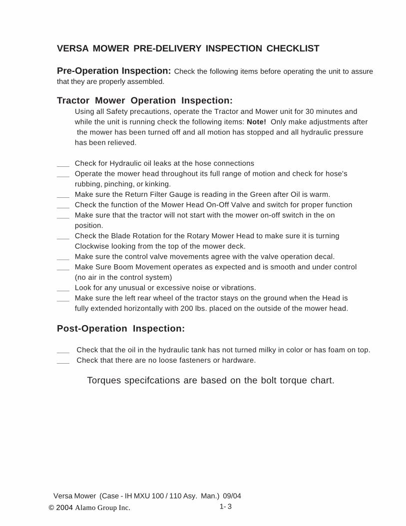
Tractor Mower Operation Inspection:Using all Safety precautions, operate the Tractor and Mower unit for 30 minutes andwhile the unit is running check the following items: Note! Only make adjustments after the mower has been turned off and all motion has stopped and all hydraulic pressurehas been relieved.
___ Check for Hydraulic oil leaks at the hose connections___ Operate the mower head throughout its full range of motion and check for hose's
rubbing, pinching, or kinking.___ Make sure the Return Filter Gauge is reading in the Green after Oil is warm.___ Check the function of the Mower Head On-Off Valve and switch for proper function___ Make sure that the tractor will not start with the mower on-off switch in the on
position.___ Check the Blade Rotation for the Rotary Mower Head to make sure it is turning
Clockwise looking from the top of the mower deck.___ Make sure the control valve movements agree with the valve operation decal.___ Make Sure Boom Movement operates as expected and is smooth and under control
(no air in the control system)___ Look for any unusual or excessive noise or vibrations.___ Make sure the left rear wheel of the tractor stays on the ground when the Head is
fully extended horizontally with 200 lbs. placed on the outside of the mower head.
Post-Operation Inspection:
___ Check that the oil in the hydraulic tank has not turned milky in color or has foam on top.___ Check that there are no loose fasteners or hardware.
Torques specifcations are based on the bolt torque chart.

© 2004 Alamo Group Inc. 1- 4Versa Flail (Case - IH MXU 100 / 110 Asy. Man.) 09/04
NOTES

© 2004 Alamo Group Inc. 2- 1Versa Flail (Case - IH MXU 100 / 110 Asy. Man.) 09/04
VERSA MOWERGeneral Information
Case -IH Tractor MXU 100 / 110 Cab/4wd
Section 2

© 2004 Alamo Group Inc. 2 - 2Versa Flail (Case-IH MXU 100 / 110 Asy. Man.) 09/04
To help you assemble your new Versa and mount it to your tractor, we provide you withdrawings, instructions and general information. When needed, you can get information orclarification from Alamo Group Customer Service or from engineering departments over the phone.
This publication provides general information not specifically for your case or tractor, but, inconnection with the drawings, this publication offers you some valuable assistance - please read itthoroughly.
These mount kits are made for selected tractors with standard configurations. Only the notedoptions and tire sizes listed on the installation drawings will work with these mount kits. Otheroptions, front axles, or different tire sizes may prevent the mount kit from fitting your non - standardtractor. Alamo Group cannot take responsibility for these problems or any modifications made tothe unit.
These instructions have been prepared to assist you in the correct procedure for mountingan Alamo Group A-Boom on your tractor.
Throughout these instructions, references are made to right or left directions. Right and leftare determined by sitting on the tractor seat and facing the direction of travel.
This is the Safety-Alert symbol. When you see this symbol on your machine or inthese instructions, be alert to the potential for personal injury.
Follow recommended precautions for safe assembly and operating practices.
DANGER! A signal word - DANGER, WARNING, or CAUTION - is used with theSafety Alert symbol identifies the most serious hazards.
WARNING! Safety signs with signal word WARNING are typically used to point outmore serious hazards.
CAUTION! General precautions are listed on CAUTION safety sign. CAUTION alsocalls attention to safety messages in these instructions.
NOTE: Included in the packing box of this unit is a replacement filter element for filter assembly inthe tank. This mower unit's hydraulic components have been carefully cleaned and pack-
aged at the factory to prevent contamination from entering the system. However, dust anddirt particles may enter into the sealed components through transportation,handling, rain or just sitting in a dirty or harsh environment. Therefore to assure that thehydraulic system is p r o p -erly clean please adhere to the following procedure.
1. Prepare the area where the unit is to be assembled. The area should be on a hard concretefloor that has been swept clean of all dust and contaminants. Un-package the mower unitcarefully so that the seals on the hydraulic components are not broken or pulled off. Lay outparts to make location easy. Figure 1
2. Inspect and clean all hydraulic hoses and fittings prior to installing them onto the tractor ormower. If dirt or material is seen in any of the parts, they should be washed and cleanedthoroughly with an oil-compatible solution. Do not blow the material further into a hose sincethis sometimes does not remove the foreign material and can cause damage to hydrauliccomponents down stream.
General Information
© 2004 Alamo Group Inc. 2- 3Versa Flail (Case - IH MXU 100 / 110 Asy. Man.) 09/04
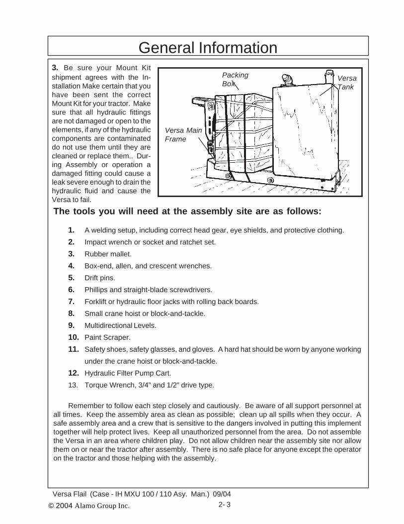
PackingBox
VersaTank
Versa MainFrame
3. Be sure your Mount Kitshipment agrees with the In-stallation Make certain that youhave been sent the correctMount Kit for your tractor. Makesure that all hydraulic fittingsare not damaged or open to theelements, if any of the hydrauliccomponents are contaminateddo not use them until they arecleaned or replace them.. Dur-ing Assembly or operation adamaged fitting could cause aleak severe enough to drain thehydraulic fluid and cause theVersa to fail.The tools you will need at the assembly site are as follows:
1. A welding setup, including correct head gear, eye shields, and protective clothing.2. Impact wrench or socket and ratchet set.3. Rubber mallet.4. Box-end, allen, and crescent wrenches.5. Drift pins.6. Phillips and straight-blade screwdrivers.7. Forklift or hydraulic floor jacks with rolling back boards.8. Small crane hoist or block-and-tackle.9. Multidirectional Levels.10. Paint Scraper.11. Safety shoes, safety glasses, and gloves. A hard hat should be worn by anyone working
under the crane hoist or block-and-tackle.12. Hydraulic Filter Pump Cart.13. Torque Wrench, 3/4” and 1/2” drive type.
Remember to follow each step closely and cautiously. Be aware of all support personnel atall times. Keep the assembly area as clean as possible; clean up all spills when they occur. Asafe assembly area and a crew that is sensitive to the dangers involved in putting this implementtogether will help protect lives. Keep all unauthorized personnel from the area. Do not assemblethe Versa in an area where children play. Do not allow children near the assembly site nor allowthem on or near the tractor after assembly. There is no safe place for anyone except the operatoron the tractor and those helping with the assembly.
General Information

© 2004 Alamo Group Inc. 2 - 4Versa Flail (Case-IH MXU 100 / 110 Asy. Man.) 09/04
General Information
DASH NOMINAL TORQUE VALUE*SIZE SIZE (IN.) (IN.LBS.) (FT.LBS.)-4 1/4 140 12-6 3/8 230 19-8 1/2 450 38-10 5/8 650 54-12 3/4 900 75-16 1 1200 100-20 1-1/4 1600 133-24 1-1/2 2000 167-32 2 2800 233* Straight threads do not always seal better when higher torques areused. Too much torque causes distortion and may lead to leakage.
RECOMMENDED HOSE END TORQUE VALUES FOR 37DEGREE ANGLE STEEL HOSE END FITTINGS
RECOMMENDED TORQUE VALUES CHART:
RECOMMENDED TORQUE IN FT.-LBS. (Nm)COARSE AND FINE THREADS
2 (B) 5 (D) 8 (F)
Bolt Plain Three SixDia. Head Dashes Dashes
1/4" Not used 10 (14) 14 (19)5/16" Not used 20 (27) 30 (41)3/8" Not used 35 (47) 50 (68)7/16" 35 (47) 55 (75) 80 (108)1/2" 55 (75) 85 (115) 120 (163)9/16" 75 (102) 130 (176) 175 (237)5/8" 105 (142) 170 (230) 240 (325)3/4" 185 (251) 300 (407) 425 (576)7/8" 160 (217) 445 (603) 685 (929)1" 250 (339) 670 (908) 1030 (1396)1-1/8" 330 (447) 910 (1234) 1460 (1979)1-1/4" 480 (651) 1250 (1695) 2060 (2793)
RECOMMENDED TORQUE VALUES CHART:

© 2004 Alamo Group Inc. 2- 5Versa Flail (Case - IH MXU 100 / 110 Asy. Man.) 09/04
General InformationIMPORTANT: Change the return filter in tank and suction filters after the first 200 hours of
operation. Change the filters again at 700 hours; then, change the oil and filters at1600 hours. After that, continue to change the filter every 800 hours and the oilevery 1600 hours. Hydraulic oil to be used is Universal Tractor Hydraulic . Use theabove procedures as part of a good filter maintenance program.
Between filter changes, monitor condition of filter by reading PressureGauge mounted on filter on top of the Tank. If pressure reads 15 psi or greater at1800 RPM engine speed and normal operating temperature (140 deg. F. orgreater), filter element should be changed. Pressure gauges are color-coded tohelp indicate when to change element.
Escaping fluid under pressure can penetrate the skin causing seriousinjury. Relieve pressure before unhooking hydraulic or other lines. Tighten allconnections before applying pressure. Keep hands and body away from pinholesand nozzles which eject fluids under high pressure. Use a piece of cardboard tosearch for leaks. If ANY fluid is injected into the skin, it must be surgicallyremoved within a few hours by a doctor familiar with this type injury or gangrenemay result.
To prevent personal injury, always wear SAFETY SHOES, SAFETYGLASSES, and GLOVES. A HARD HAT should be worn by anyone workingunder a Crane Hoist orBlock-and Tackle.
When working with or on the machine, take care and stay alert. Always becareful. Always be alert for hazards. Watch out for others.
ALWAYS USE GLOVES WHEN HANDLING THE BLADES! Before removing or installing blades, make sure that the head is leaned back past thevertical position. If the head is not, the blades can come off suddenly when thebolts are removed.
Block up or securely support components before working under or aroundlifted components. Inadvertent falling can cause serious injury or death.
The operator should not leave his seat with this valve engaged orwith the tractor engine running. Allow approximately 60 seconds for theblades to come to rest after turning the switch off before dismounting.
CAUTION!
WARNING!
CAUTION!
WARNING!
WARNING!
CAUTION!

© 2004 Alamo Group Inc. 2 - 6Versa Flail (Case-IH MXU 100 / 110 Asy. Man.) 09/04
NOTES
© 2004 Alamo Group Inc. 3- 1Versa Flail (Case-IH MXU 100 / 110 Asy. Man.) 09/04
VERSA FLAILMainframe and Flail Head
Installation
Case -IH Tractor MXU 100 / 110 Cab/4wd
Section 3

© 2004 Alamo Group Inc. 3- 2Versa Flail (Case-IH MXU 100 / 110 Asy. Man.) 09/04
Item Part No. Qty. Description
1 ------------ 1 Case-IH MXU 100 / 110 Tractor Chassis2 02981218 1 Front Mount Plate, LH Side3 02981219 1 Front Mount Plate, RH Side4 02981518 2 Rear Mount Plate, LH or RH Side5 02887200 1 Versa Frame Weldment6 02978816 2 Plate, Versa Weld On7 02879100 1 Flat, Axle Mount Bracket8 02981723 1 Stabilizer Weldment, Rear Axle Mount9 02980719 1 Pump Mount Asy. w/ Cover10 02961826 1 Pump Asy.11 02959390 14 Bolt, 3/4” NC X 2-1/4 Gr. 812 00000200 14 Nut, 3/4” NC13 00003901 14 Heavy Lockwasher, 3/4”14 5312316 2 Hardened Flatwasher, 3/4”15 02975692 20 Bolt, M20-P2.5 X 50 mm Gr. 10.916 02971158 20 Lockwasher, 20 mm17 02970066 4 Lockwasher. 18 mm18 02977576 4 Bolt, M18-1.5 X 60 mm Gr. 10.919 ------------ 1 3 Point Stabilizer Bracket (On Tractor)
1
2
3
4
5
6
7
8
9 10
11, 12, 13, 14 11, 12, 1315, 16
17, 18
19
15, 16
Figure 1
Versa Frame

© 2004 Alamo Group Inc. 3- 3Versa Flail (Case-IH MXU 100 / 110 Asy. Man.) 09/04
Versa Frame1. Versa Frame Mounting Components.Shown in Figure 1 are the parts needed to mountthe versa frame to the tractor. Follow instructionslisted below and reference back to figure 1 asneeded.2. Remove The factory Brackets. Thereis a factory mounting bracket on each side of thetractor which if for mounting options on the trac-tor. The one on the RH side bolts behind thebattery box and the LH side it bolts behind the fueltank, the tank may have to be lossened andmoved outward to get to the bracket bolts. Thesebracket will be removed and not used. (See Fig-ure 2)3. Install Versa Frame Mounting Brack-ets. The bolt holes in the tractor frame will beused to mount the front and the rear versa framemounting brackets. The Rear Mounting BracketsP/N ----------------- (LH or RH same bracket). Thefront mounting brackets has a RH (P/N02981219) & LH (P/N 02981218), make certainthat they are mounted correctly. The FrontMounting bracket will have a metal hose ring (P/N02978281) that will need to be welded to them,one for each side If Mounted correctly the frontand rear LH & RH brackets will be the samewidth apart at the bottom where each has thethree holes. (See Figure 3).4. Install Versa Mount Plate to MountingBrackets. The mounting Plates (LH & RH side)will bolt to the mounting brackets using the sixbolts on each side. Bolt these plates to the out-side of the mounting brackets. Install all six boltsand snug them only as you will be removing them
Removed TractorParts that will not be
used
Figure 2
Rear Mounting BracketP/N 02980739 RH or LHFigure 3
Hose Ring
Front Mounting Bracket LH P/N 02980737 &RH P/N 02980738 w/ Hose Ring P/N02978281 Welded on
Figure 4Versa Mount PlateP/N 02978816
later to completely weld them to the versa frame (See Figure 4)

© 2004 Alamo Group Inc. 3- 4Versa Flail (Case-IH MXU 100 / 110 Asy. Man.) 09/04
Versa Frame
Figure 5Versa Frame Weldment
5. Fitting The Versa Frame. Using afloor jack insert the versa frame up under thetractor. The Versa Frame will fit up against theversa mount plate (See Figure 4). DO NOT doany welding of the versa frame until instructedto. The Versa Frame will have to be aligned fordistance Left to Right.
6. Aligning Versa Frame with MountingBrackets. The Versa Frame must be alignedwith the mounting frame to where it will extendout past mounting plate 9-1/4” on the right handside as shown in Figure 6. This measurementis important and must be correct in order formower to operate correctly. The Versa Frameshould be lower in the front by approximately 1/8” than in the back, this allows the mower tooperate with the front of the mower a little lowerthan the rear. Once the measurements are cor-rect check the versa frame for level. These levelchecks can be done on the LH side using abubble level (See Figure 8) if leveled correctlythen tack weld the versa frame to the mountingplate on both sides of the tractor, the tack weldsneed to be strong enough to hold the versaframe up. Recheck all measurements (See Fig-ure 6). Make certain that the RH side (Shown)and the LH side mount plate is tack welded tothe Versa Frame. The Tack weld must be suffi-cient enough to support the versa frame to themounting plate when unbolted.
7. Install Frame Stabilizer to Axle andVersa Frame. There is a stabilizer weldment(P/N 02981723) that connect to Versa Frameand tractor rear axle. Front of the stabilizer willbolt to a flat bracket (P/N 02879100) that will betack welded to the Versa Frame. Rear axle willkeep the factory 3 point stabilizer bracket boltedback up below the stabilizer bracket. (See Fig-ure 7). After bolting the flat stabilizer mountingbracket to the front of the stabilizer, tack weld itto the versa frame. (See Figure 7) DO NOTRemove Versa frame yet the Hydraulic Tankmust be fitted to the Versa frame and themounting tabs welded on to the versa frame(See Step 8 & Figure 8).
Stabilizer WeldmentP/N 02980750
Tractor 3 PointStabilizer
Flat AxleMount BracketP/N 02879100
Tractor RHAxle Housing
Figure 7
9-1/4”
Tack Weld Here, Both Sides
TackWeldHereLooking
at RHSidefromfront oftractor
Figure 6

© 2004 Alamo Group Inc. 3- 5Versa Flail (Case-IH MXU 100 / 110 Asy. Man.) 09/04
Versa Frame8. Fit Hydraulic Tank. The Oil Tank (AsyP/N 02980869) is a manufactured tank de-signed to fit behind the LH rear wheel under thevender (See Figure 8, 9 & 10). It is easiest tomount the Tank with the Left rear wheel re-moved. The tank will mount with the suctiontube connection under the fender pointing to-ward the front of the tractor. The Fill cap andreturn hose connection will be to the rear behindthe tractor (See Figure 10).9. Install the Versa Frame Step. TheVersa Frame Step will NOT be welded to theside of the versa frame as on some other mod-els because the LH Factory Tractor Step isretained to be used on this model Tractor (SeeFigure 11) The step is shown being reinstalledas it was removed to allow the fuel tank to bemoved outward to allow the removal of the fac-tory install accessory bracket , also it will beeasier to tighten the rear frame mountingbracket to the tractor (See Figures 3. 4 & 5).10. Install Stabilizer weldment to Rearaxle. The stabilizer weldment bolts to the RHrear Tractor Axle up under the bottom side. Theoter end will be bolted to the frame where the lughas been welded on. (See Figures 12 , 14 & 35)This is a two person job, one in front and one inrear under tactor (See Figure 35). The FlatMounting lug (P/N 02879100) will need to betack welded to the mainframe (See Figure 12 &14) for welding later (See Figure 12)
Figure 8
Hyd Tank BehindWheel Under fender
Figure 9
Suction HoseConnection
Tank Fill Tube
Return HoseConnection
Operators ManualCannister
Figure 10 Figure 11
© 2004 Alamo Group Inc. 3- 6Versa Flail (Case-IH MXU 100 / 110 Asy. Man.) 09/04
Versa Frame
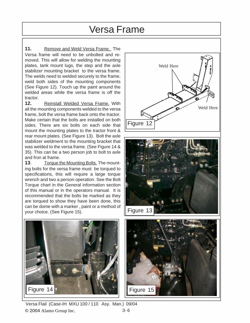
11. Remove and Weld Versa Frame. TheVersa frame will need to be unbolted and re-moved. This will allow for welding the mountingplates, tank mount lugs, the step and the axlestabilizer mounting bracket to the versa frame.The welds need to welded securely to the frame,weld both sides of the mounting components(See Figure 12). Touch up the paint around thewelded areas while the versa frame is off thetractor.12. Reinstall Welded Versa Frame. Withall the mounting components welded to the versaframe, bolt the versa frame back onto the tractor.Make certain that the bolts are installed on bothsides. There are six bolts on each side thatmount the mounting plates to the tractor front &rear mount plates. (See Figure 13). Bolt the axlestabilizer weldment to the mounting bracket thatwas welded to the versa frame. (See Figure 14 &35). This can be a two person job to bolt to axleand fron at frame.13. Torque the Mounting Bolts. The mount-ing bolts for the versa frame must be torqued tospecifications, this will require a large torquewrench and two a person operation. See the BoltTorque chart in the General information sectionof this manual or in the operators manual. It isrecommended that the bolts be marked as theyare torqued to show they have been done, thiscan be dome with a marker , paint or a method ofyour choice. (See Figure 15).
Weld Here
Weld Here
Figure 12
Figure 13
Figure 14 Figure 15
© 2004 Alamo Group Inc. 3- 7Versa Flail (Case-IH MXU 100 / 110 Asy. Man.) 09/04
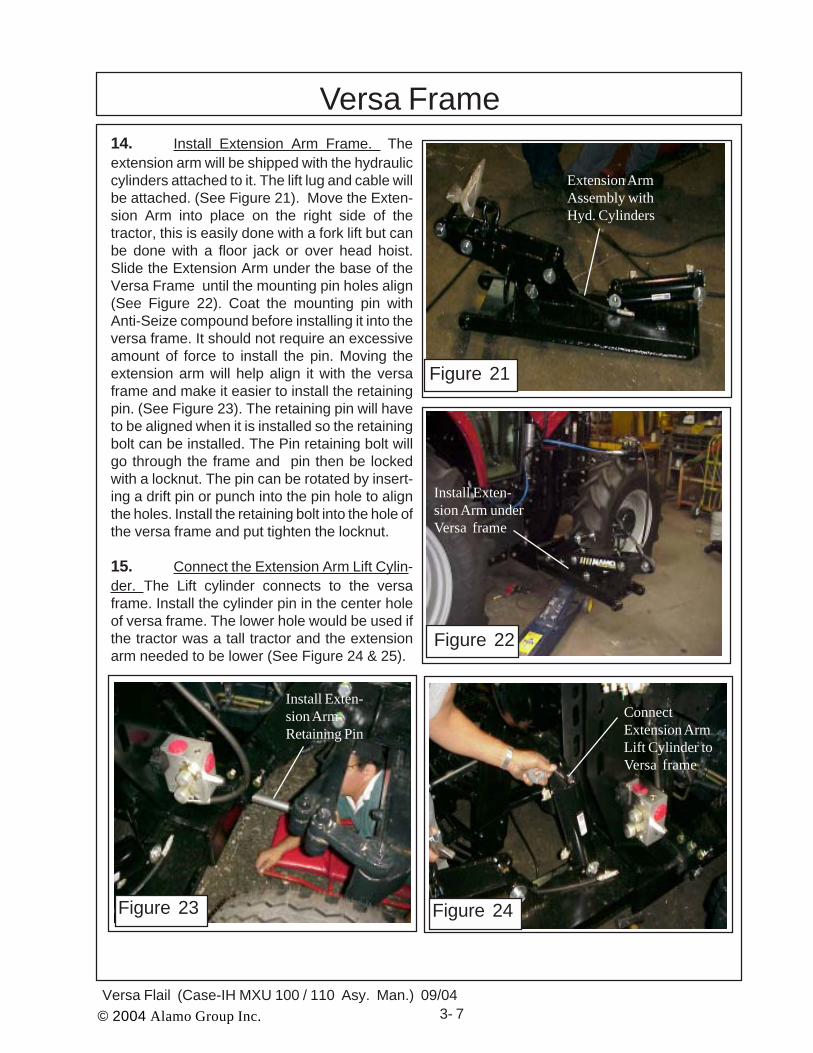
Versa Frame14. Install Extension Arm Frame. Theextension arm will be shipped with the hydrauliccylinders attached to it. The lift lug and cable willbe attached. (See Figure 21). Move the Exten-sion Arm into place on the right side of thetractor, this is easily done with a fork lift but canbe done with a floor jack or over head hoist.Slide the Extension Arm under the base of theVersa Frame until the mounting pin holes align(See Figure 22). Coat the mounting pin withAnti-Seize compound before installing it into theversa frame. It should not require an excessiveamount of force to install the pin. Moving theextension arm will help align it with the versaframe and make it easier to install the retainingpin. (See Figure 23). The retaining pin will haveto be aligned when it is installed so the retainingbolt can be installed. The Pin retaining bolt willgo through the frame and pin then be lockedwith a locknut. The pin can be rotated by insert-ing a drift pin or punch into the pin hole to alignthe holes. Install the retaining bolt into the hole ofthe versa frame and put tighten the locknut.
15. Connect the Extension Arm Lift Cylin-der. The Lift cylinder connects to the versaframe. Install the cylinder pin in the center holeof versa frame. The lower hole would be used ifthe tractor was a tall tractor and the extensionarm needed to be lower (See Figure 24 & 25).
Figure 21
Figure 23 Figure 24
Install Exten-sion ArmRetaining Pin
ConnectExtension ArmLift Cylinder toVersa frame
Extension ArmAssembly withHyd. Cylinders
Figure 22
Install Exten-sion Arm underVersa frame

© 2004 Alamo Group Inc. 3- 8Versa Flail (Case-IH MXU 100 / 110 Asy. Man.) 09/04
Versa Frame
Figure 25
16. Cutter Valve and Cylinder ControlValve. The cutter valve and the cylinder controlvalve are mounted on the versa frame andshould be already bolted on to it when it isshipped to you. If they are not they will need tobe bolted on. The mounting plates for the valvesare attached to the versa frame, the valves willbolt on to them. (See Figure 24 & 25).
17. Connect Head to Extension Arm. TheHead has an option, a rotary or a flail head, theywill both connect to the extension arm. Thehead will be shipped assembled with the headattaching pin installed into the head. (See Figure26). Remove the head attaching pin from thehead (See Figure 26). The Motor Hoses areattached to the head, the motor hoses need tobe put through the hose ring on the extensionarm as head is moved toward the extensionarm (See Figure 27). As the head is movedcloser to the extension arm the hoses slidefurther through the hose ring (See Figure 27).Slide the head inward until the mounting lugs onthe extension arm are aligned with the mountingtube on the head (See Figure 28). Coat theretaining pin with anti-seize and insert it into theextension arm lugs, make certain to keep theretaining bolt hole in pin aligned with hole inhead mounting tube. When pin is in install theretaining bolt and locking nut (See Figure 28).
Figure 26
Head Attaching Pin
Figure 28
Align extension armlugs and head mounttube here.
Cutter MotorControl Valve
CylinderControl Valve
Figure 27
Insert Motor Hosesthrough hose ring

© 2004 Alamo Group Inc. 3- 9Versa Flail (Case-IH MXU 100 / 110 Asy. Man.) 09/04
Versa Frame
18. Connect the Head Tilt Cable to Head.The Tilt cylinder lifts the frame weldment andthe frame weldment is attached to the head witha cable and clevis assembly (See Figure 29).Unscrew the clevis and attach it to the decklifting lug and tighten it.. (See Figure 29).
19. Connect the Motor Hoses to the Cut-ter Valve. The Motor has two hose connected toit and running through the hose ring on exten-sion arm toward the cutter valve. It is importantto ID which hose is which through the sleevingas these hose must correctly be attach to thecutter valve. The two hoses one is on the frontside and one is on the back side of the mowerdeck, The one on the back side (toward the rearof the deck) is the pressure side (See Figure30). Connect the Pressure hose to the upperfitting of cutter valve, these are the two largefittings pointing toward mower head (See Figure31 & 32). Note: the Cylinder Control valve returnhose is routed through the cutter valve, it is thesmaller hose that connects into the bottom ofthe cutter valve. The return hose will need to berouted so that it clears the front tire of tractor aswell as the frame components (See Figure 31).
Figure 29
Figure 32
Pressure Hose To Motor
Return HoseFrom Motor
Pressure Hose From Pump
Return HoseTo Tank
Connect theReturn Hosefrom MotorHere M2
Connect thePressure Hose toMotor Here M1
Return HoseFrom Cyl. Control Valve
Figure 31
Pressure Hosefrom Cutter ValveM1 Side
Return Hose backto Cutter ValveM2 Side
Figure 30
© 2004 Alamo Group Inc. 3- 10Versa Flail (Case-IH MXU 100 / 110 Asy. Man.) 09/04
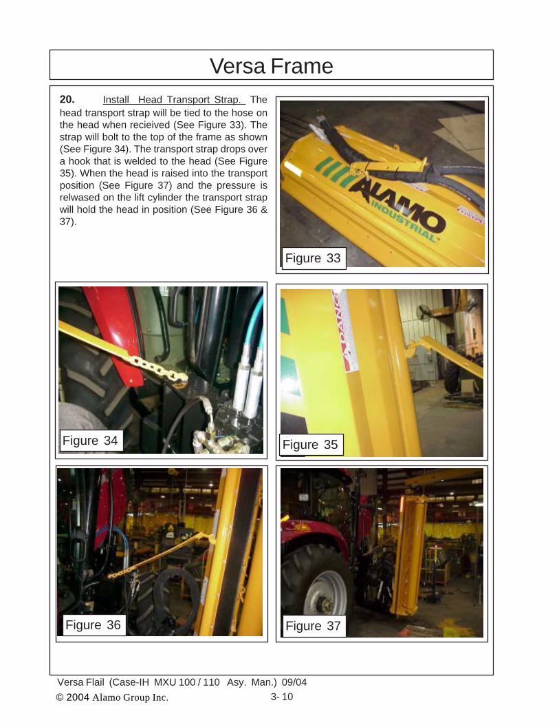
Versa Frame20. Install Head Transport Strap. Thehead transport strap will be tied to the hose onthe head when recieived (See Figure 33). Thestrap will bolt to the top of the frame as shown(See Figure 34). The transport strap drops overa hook that is welded to the head (See Figure35). When the head is raised into the transportposition (See Figure 37) and the pressure isrelwased on the lift cylinder the transport strapwill hold the head in position (See Figure 36 &37).
Figure 33
Figure 34 Figure 35
Figure 36 Figure 37
© 2004 Alamo Group Inc. 3- 11Versa Flail (Case-IH MXU 100 / 110 Asy. Man.) 09/04
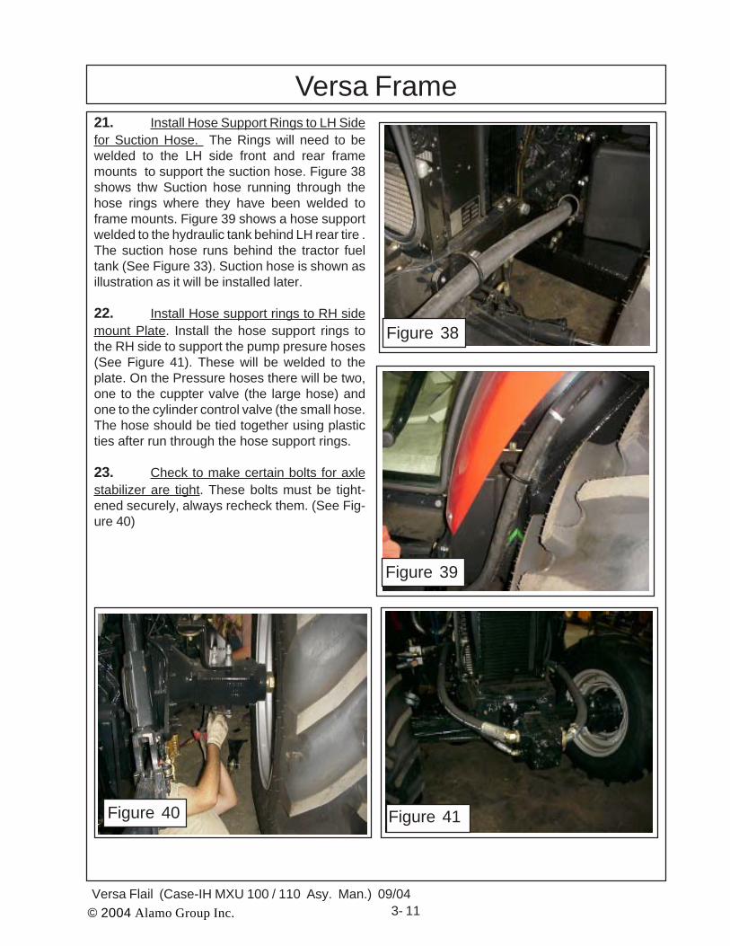
Versa Frame21. Install Hose Support Rings to LH Sidefor Suction Hose. The Rings will need to bewelded to the LH side front and rear framemounts to support the suction hose. Figure 38shows thw Suction hose running through thehose rings where they have been welded toframe mounts. Figure 39 shows a hose supportwelded to the hydraulic tank behind LH rear tire .The suction hose runs behind the tractor fueltank (See Figure 33). Suction hose is shown asillustration as it will be installed later.
22. Install Hose support rings to RH sidemount Plate. Install the hose support rings tothe RH side to support the pump presure hoses(See Figure 41). These will be welded to theplate. On the Pressure hoses there will be two,one to the cuppter valve (the large hose) andone to the cylinder control valve (the small hose.The hose should be tied together using plasticties after run through the hose support rings.
23. Check to make certain bolts for axlestabilizer are tight. These bolts must be tight-ened securely, always recheck them. (See Fig-ure 40)
Figure 39
Figure 40
Figure 38
Figure 41

© 2004 Alamo Group Inc. 3- 12Versa Flail (Case-IH MXU 100 / 110 Asy. Man.) 09/04
Versa Frame24. Motor Hose Requirements. The Mo-tor hoses will be attached to the head when theyare received (See Figure 42). There are elbowsconnecting the hoses to the motor. On the 4wheel drive is is IMPORTANT as to how theseelbows are turned as the front tires will hit themif they are turned wrong (See Figure 43). Notethe back elbow is the way it was sent from thefactory and will be ok on two wheel drive. BUTON 4 WHEEL DRIVE the elbow MUST beturned as shown (See Figure 43) to clear thefront wheel.
25. Hose must be through the Hose Ringon Frame. The Motor hose must be run throughthe hose ring (See Figure 44) on lift frame be-fore connectint them th the cutter valve (SeeFigure 45). The elbows on the cutter valveshould be turned as shown (See Figure 45).
Figure 42
Figure 43
Elbow TurnedCorrect
Elbow TurnedWrong
Figure 45Figure 44
© 2004 Alamo Group Inc. 4 - 1Versa Flail (Case-IH MXU 100 / 110 Asy. Man.) 09/04
VERSA FLAILPump, Driveshaft,Cyl. Control Valve
& Cutter Valve
Case -IH Tractor MXU 100 / 110 Cab/4wd
Section 4

© 2004 Alamo Group Inc. 4 - 2Versa Flail (Case-IH MXU 100 / 110 Asy. Man.) 09/04
Pump & DriveshaftInstalling Pump, Pump Drive Components and Hydraulic Tank:
This Section covers the installation of Pump Drive Components, Pump Assembly and theHydraulic Tank. Some precautions must be followed during the Assembly Process and before unitis ever started for the first time.1. Tractor must be disabled to prevent accidental engine start and prevent damage to compo-
nents.2. All Fittings, Hose, Cylinders, Tank must be kept plugged at all times, No part of the Hydraulic
System can be left open at any time during mounting process, this will keep system clean.3. All Tools, Work Area, Components and Workers Hands must remain Clean when working on
any part of the Hydraulic System.4. All components should be rechecked for tightness at least twice, Hose routing also double
checked.Preparing Tractor Front Plate (Bolster) to Slide Driveline in FromEngine Side :1. Identify the front Bolster access holes,Remove the two rubber plugs that should be inthe existing large holes of bolster. The Air Pre-Cooler lower plate can be removed if wanted.The shaft part of the driveline that has to slide inthrough the bolster from the engine side of theradiator, the flange yoke will be in so it can beconnected to the pulley adapter (See Figure 1).
2. Install Pulley Adapter. The Pulleyadapter (P/N 02980699) is a round plate with4 threaded holes and four non-threaded holesin it. Notice this pulley adapter will not have acenter hole in it (See Figure 2). The four non-threaded holes are used to mount the Adapterto the Crankshaft Pulley using bolts (P/N02980720) 12 mm X 40 mm long andlockwashers (P/N 00754566) 12 mm thatare supplied in mount kit. The four threadedholes are used to install the flange yoke ofdriveline to pulley adapter Do not use longerbolts to mount Pulley Adapter to Pulley orFlange yoke to adapter than are suppliedwith mounting kit, if longer bolts are used theycould go through adapter and pulley causingdamage. Tighten the four bolts that retain thepulley adapter to the pulley now, it will beeasier than trying to tighten them later.
ExistingHoles have
rubberPlugs in
them
TractorBolster
Four Non-Threaded HolesFour
ThreadedHoles
Pulley AdapterP/N 02980699
Figure 1
Figure 2

© 2004 Alamo Group Inc. 4 - 3Versa Flail (Case-IH MXU 100 / 110 Asy. Man.) 09/04
3. Install Shaft Half of Driveline withFlange Yoke. Note the driveline universaljoints should be timed (See Figure 3). Slidethe two driveline half assemblies apart andlay the tube half aside for now. Make certainthat the four retaining bolts for the Pulleyadapter to the crankshaft pulley have beentightened.
From the side of the tractor (RH side)slide the Shaft Half of driveline shaft end firstdown into the opening below the radiatorfrom engine side, insert it through theexisting hole and/or cut hole combinationuntil the shaft is pointed toward the
Splined Clamp Yoke/ Tube End
Flange Yoke/ Shaft End
Drive ShaftAssembly
Pump & Driveshaft
Figure 3
front of the tractor, and the flange yoke is over far enough to align with the four threaded pulleyadapter holes.
Align the four holes in the flange yoke of driveline with the four threaded holes in thepulley adapter. Install the four retaining 7/16" X 1-1/4" long bolts (P/N 02976344) and 7/16"lockwasher (P/N 00022200) into flange yoke into adapter, tighten them at this time. Thesefour bolts can be tightened by using a long socket extension run through along side thedriveline shaft.
Set the tube end of driveshaft aside for now as it will be installed later. But alwaysremember the driveline universal joint must be aligned (timed) when assembling the drivelinehalves.Installing Pump Mounting Weldment :1. Install Pump Mounting Weldment. The Pump Mount Weldment (Asy. P/N 02980719 w/cover) bolts to the front of the tractor bolster using four 20 mm X 45 mm long bolts (P/N02975959) and 20 mm lockwashers (P/N 02971158) . Install the Pump Mounting Weldment(P/N 02980666) with the opening for the driveline cover up. Tighten the four mounting bolts now.(See Figure 4)
1234567890123456789012345678901234567890
123456789123456789123456789
Mounting Bolts
MountingBolts
Pump MountWeldment
Tractor Bolster
Figure 4

© 2004 Alamo Group Inc. 4 - 4Versa Flail (Case-IH MXU 100 / 110 Asy. Man.) 09/04
Installing Pump to Pump Mount Weldment :1. Install Pump to Pump Mount Weldment. The Pump has the tube half of driveline attachedand clamp yoke tightened. To install the pump and driveline half it is best to use an assistantor overhead hoist to help you align the drivelines halves as they are slid together, the Drivelinemust be timed (universal joints aligned the same) as shown in the pump & driveline schematicon (See Figure 6, 7, 8 & 9). Slide Driveline half and pump together until the shoulder onthe pump slide in the hole on the pump mount weldment.
When installing the pump always keep ports sealed to keep them clean and free ofcontamination. The pump MUST be turned correctly. The suction Port (side with single port mustbe to the left side (sitting in tractor seat) so the suction hose will connect to it. The dual port sidewill be to the right side of tractor (as sitting in tractor seat). The top port on the right side is forthe pressure feed to the motor on the cutting head. The bottom port on the right side is thepressure supply for the cylinder control valve. (See Figure 6).
Install the two 1/2" X 1-1/2" long pump mount bolts (P/N 02892000) and two 1/2"lockwashers (P/N 00001300). Tighten the two pump mounting bolts. DO NOT Start Tractorafter pump has been installed until all hydraulic connections have been made and filling willoil procedure has been completed. If tractor is started with pump dry it and the hydraulicsystem will be damaged.
Installing Pump Driveline Cover :1. Install Pump Driveline Cover. The Pump Driveline will have a cover (P/N 02980398)which retained by four 1/4" X 3/4" bolts (P/N 00021400), four 1/4" flatwashers (P/N 00024100)and four 1/4" lockwashers (P/N 00017000), install and tighten these now (See Figure 6).
Installing Driveline Half to Pump :1. Install Driveline Half to Pump. Install the clamp yoke of the tube half of driveline ontothe pump, slide the clamp yoke on pump shaft until you have about 1/8" to 1/4" gap betweenyoke and pump. Do not install yoke so far on pump shaft that yoke will rub against pump inanyway. Tighten the two bolts and nuts on clamp yoke at this time. (See Figure 5)
Pump & Driveshaft
123456123456123456123456
1
1
111
1234123412341234
121212
1212
1212
1212121212121212
Pump Suction Port
Pump Pressure Ports
Driveline Tube Half withClamp Yoke
123123123123123123123123
Figure 5

© 2004 Alamo Group Inc. 4 - 5Versa Flail (Case-IH MXU 100 / 110 Asy. Man.) 09/04
Pump Mounting Bolts
P/N 02980666 PumpMount Weldment
12345678901123456789011234567890112345678901
123456789012123456789012123456789012
Mounting Bolts
Bolts ToTractor Bolster
123456789123456789123456789123456789
Mounting Bolts
SuctionPort
Pump Pressure Ports (large port to motor, smallport to cyl control valve supply
12341234
11
11
1212
1234123412341234
123123
12 12
11111111
1212121212121212
Install Pump Driveline cover here
Figure 6
Pump & Driveshaft
Figure 7 Figure 8
SuctionHose
PressureHose toCutterValve
Pressure Hose to CylinderControl Valve
Pulley Adapter and Flange Yokeof Driveshaft

© 2004 Alamo Group Inc. 4 - 6Versa Flail (Case-IH MXU 100 / 110 Asy. Man.) 09/04
Pump & Driveline SchematicPump EndClamp Yoke
Tractor Engine Pulley
1234512345
Pulley Adpater w/ MountingBolts & Washers (4 bolts)
Driveline Asy
4 Driveline Mounting BoltsP/N 02980398Driveline Cover
Time Universal Joints
123123123123123123
Driveline Cover Mounting Bolts,Flatwashers & Lockwashers (4)
12341234
Pump MountingBolts, Use ExistingHardware
P/N 02980666 PumpMount Weldment
Pump Pressure Ports (large port to motor, smallport to cyl control valve supply
Pump (Reference)
123456789012123456789012123456789012123456789012
123456789011234567890112345678901
Mounting Bolts
Bolts ToTractor Bolster
123456789123456789123456789123456789
Mounting Bolts
123123
1
1
11
1234123412341234
1212
12 12
SuctionPort
1212121212121212
12121212121212
Pump & Driveshaft
Figure 9
© 2004 Alamo Group Inc. 4 - 7Versa Flail (Case-IH MXU 100 / 110 Asy. Man.) 09/04
Figure 13
Pressure Hose fromPump to Cutter valve(Largew Hose)
Pressure HosefromPump to CylinderControl Valve (SmallHose)
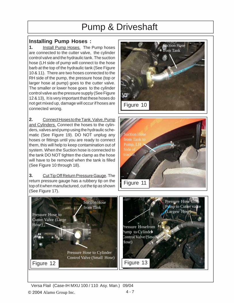
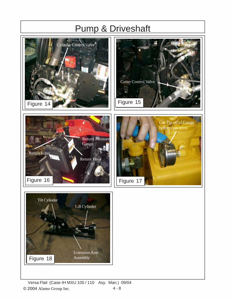
Installing Pump Hoses :1. Install Pump Hoses. The Pump hosesare connected to the cutter valve, the cylindercontrol valve and the hydraulic tank. The suctionhose (LH side of pump will connect to the hosebarb at the top of the hydraulic tank (See Figure10 & 11). There are two hoses connected to theRH side of the pump, the pressure hose (top orlarger hose at pump) goes to the cutter valve.The smaller or lower hose goes to the cylindercontrol valve as the pressure supply (See Figure12 & 13), It is very important that these hoses donot get mixed up, damage will occur if hoses areconnected wrong.
2. Connect Hoses to the Tank, Valve, Pumpand Cylinders. Connect the hoses to the cylin-ders, valves and pump using the hydraulic sche-matic (See Figure 19). DO NOT unplug anyhoses or fittings until you are ready to connectthem, this will help to keep contamination out ofsystem. When the Suction hose is connected tothe tank DO NOT tighten the clamp as the hosewill have to be removed when the tank is filled(See Figure 10 through 18).
3. Cut Tip Off Return Pressure Gauge. Thereturn pressure gauge has a rubbery tip on thetop of it when manufactured, cut the tip as shown(See Figure 17).
Pump & Driveshaft
Suction Hosefrom Tank
Figure 10
Figure 11
Suction Hosefrom Tank toPump, LHSide oftractor.
Pressure Hose to CylinderControl Valve (Small Hose)
Pressure Hose toCutter Valve (LargeHose)
Suction Hosefrom Tank
Figure 12
© 2004 Alamo Group Inc. 4 - 8Versa Flail (Case-IH MXU 100 / 110 Asy. Man.) 09/04
Figure 14 Figure 15
Figure 18
Lift CylinderTilt Cylinder
Extension ArmAssembly
Cylinder Control Valve
Cutter Control Valve
Pump & Driveshaft
Return PressureGauge
Figure 16
Return HoseReturn Filter
Figure 17
Cut Tip off of Gaugebefore operation

© 2004 Alamo Group Inc. 4 - 9Versa Flail (Case-IH MXU 100 / 110 Asy. Man.) 09/04
Hydraulic Schematic
1234123412341234
123412341234
M2
M1
123123123
123123
M2M1
12341234
123123123123
1212
123123123
12345671234567123456712345671234567123456712345671234567
123456123456123456123456
Pump (RH View)
Motor
Cyl. ControlValve
Cutter Valve
Hyd. Tank
Front Of Mower
Tilt Cylinder(Mower Fold)
Lift Cylinder(Extension Arm)
B
AA
B
Figure 19
Pump, Motor, Valves & Cylinder Schematic
Gre
en P
last
ic T
ie
Gre
en /W
hite
Pla
stic
Tie
Ora
nge
Pla
stic
Tie
Blu
e P
last
ic T
ie
Blu
e/W
hite
Pl
astic
Tie
© 2004 Alamo Group Inc. 4 - 10Versa Flail (Case-IH MXU 100 / 110 Asy. Man.) 09/04
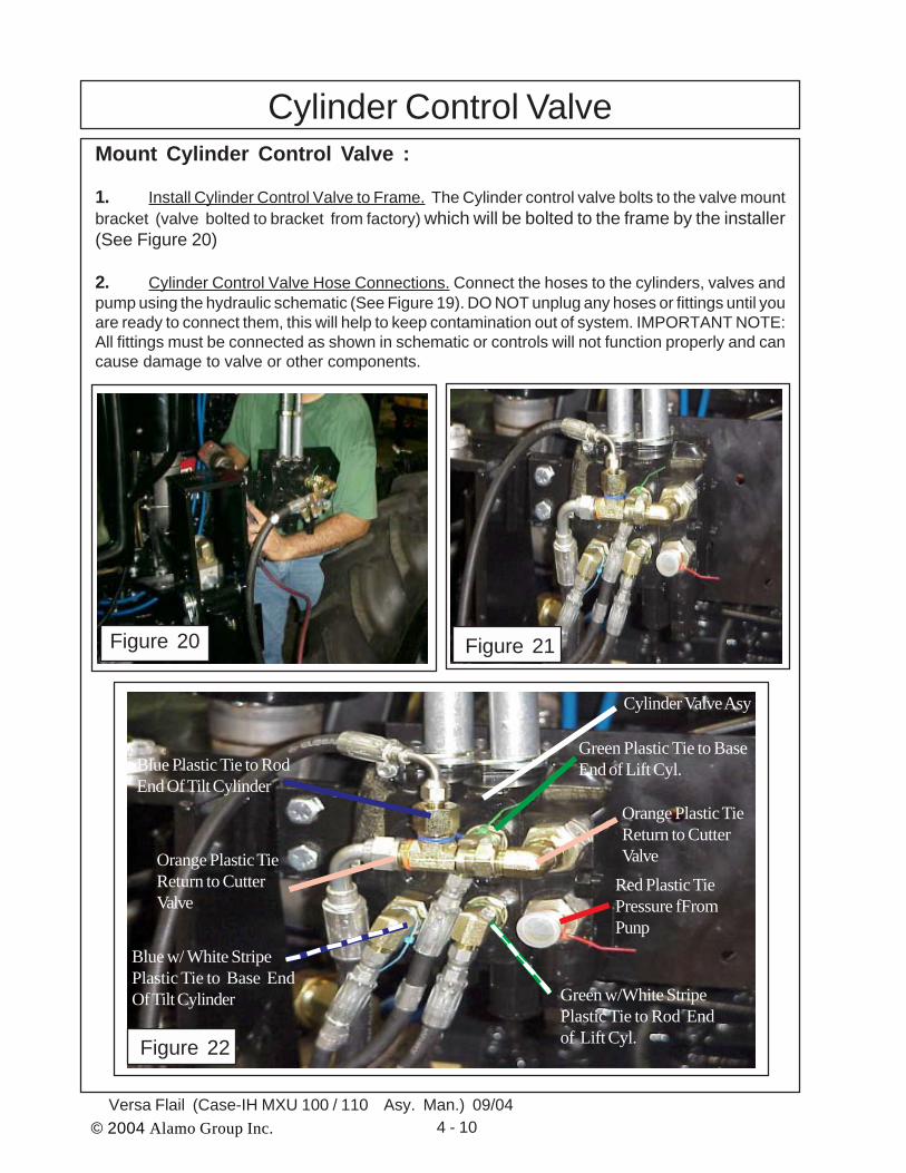
Mount Cylinder Control Valve :
1. Install Cylinder Control Valve to Frame. The Cylinder control valve bolts to the valve mountbracket (valve bolted to bracket from factory) which will be bolted to the frame by the installer(See Figure 20)
2. Cylinder Control Valve Hose Connections. Connect the hoses to the cylinders, valves andpump using the hydraulic schematic (See Figure 19). DO NOT unplug any hoses or fittings until youare ready to connect them, this will help to keep contamination out of system. IMPORTANT NOTE:All fittings must be connected as shown in schematic or controls will not function properly and cancause damage to valve or other components.
Cylinder Control Valve
Figure 20 Figure 21
Figure 22
Cylinder Valve Asy
Red Plastic TiePressure fFromPunp
Green Plastic Tie to BaseEnd of Lift Cyl.
Orange Plastic TieReturn to CutterValve
Blue Plastic Tie to RodEnd Of Tilt Cylinder
Green w/White StripePlastic Tie to Rod Endof Lift Cyl.
Blue w/ White StripePlastic Tie to Base EndOf Tilt Cylinder
Orange Plastic TieReturn to CutterValve
© 2004 Alamo Group Inc. 4 - 11Versa Flail (Case-IH MXU 100 / 110 Asy. Man.) 09/04
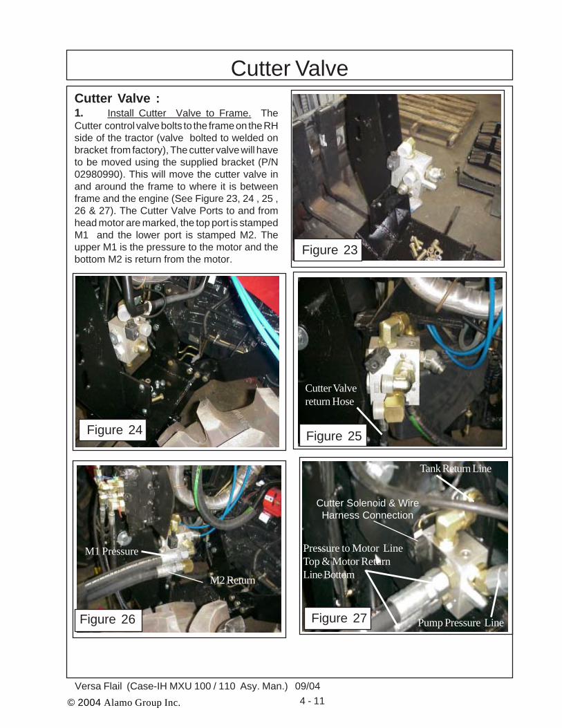
Cutter ValveCutter Valve :1. Install Cutter Valve to Frame. TheCutter control valve bolts to the frame on the RHside of the tractor (valve bolted to welded onbracket from factory), The cutter valve will haveto be moved using the supplied bracket (P/N02980990). This will move the cutter valve inand around the frame to where it is betweenframe and the engine (See Figure 23, 24 , 25 ,26 & 27). The Cutter Valve Ports to and fromhead motor are marked, the top port is stampedM1 and the lower port is stamped M2. Theupper M1 is the pressure to the motor and thebottom M2 is return from the motor.
Figure 23
Figure 24 Figure 25
Figure 26
M1 Pressure
M2 Return
Figure 27
Cutter Solenoid & WireHarness Connection
Tank Return Line
Pump Pressure Line
Pressure to Motor LineTop & Motor ReturnLine Bottom
Cutter Valvereturn Hose

© 2004 Alamo Group Inc. 4 - 12Versa Flail (Case-IH MXU 100 / 110 Asy. Man.) 09/04
NOTES
© 2004 Alamo Group Inc. 5- 1Versa Flail (Case - IH MXU 100 / 110 Asy. Man.) 09/04
VERSA MOWERCylinder Control Valve and
Cable Connections
Case -IH Tractor MXU 100 / 110 Cab/4wd
Section 5
© 2004 Alamo Group Inc. 5- 2Versa Flail (Case-IH MXU 100 / 110 Asy. Man.) 09/04
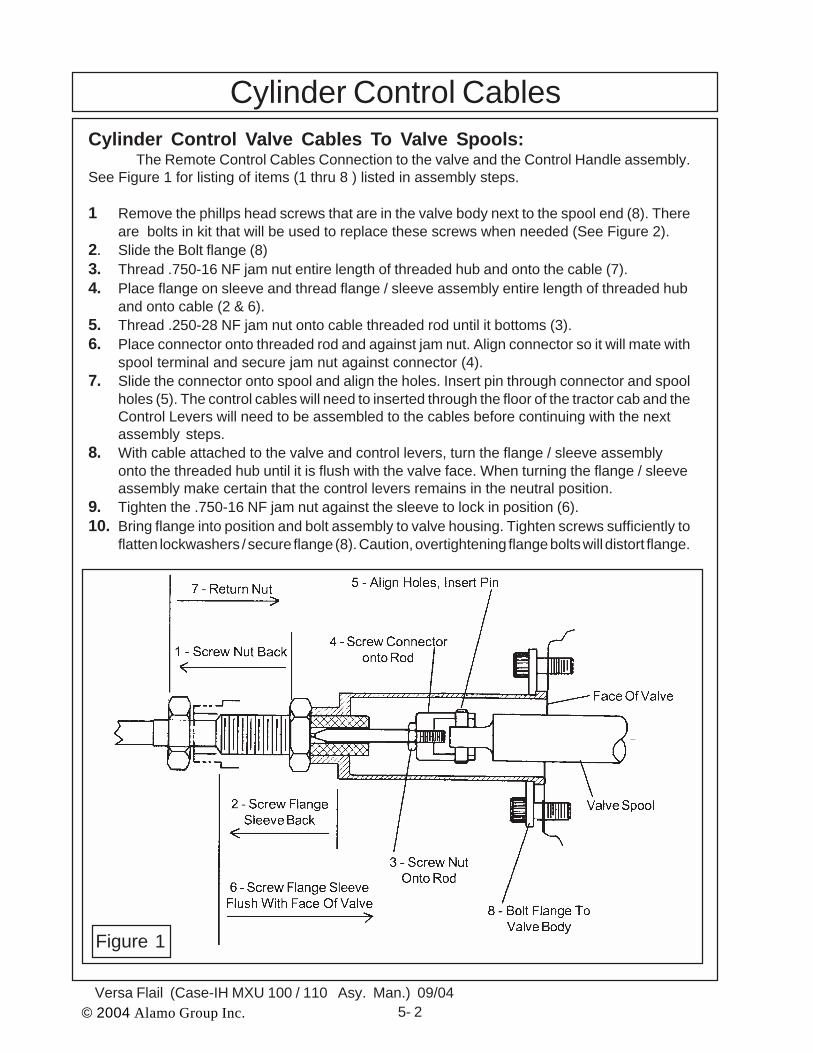
Cylinder Control CablesCylinder Control Valve Cables To Valve Spools:
The Remote Control Cables Connection to the valve and the Control Handle assembly.See Figure 1 for listing of items (1 thru 8 ) listed in assembly steps.
1 Remove the phillps head screws that are in the valve body next to the spool end (8). Thereare bolts in kit that will be used to replace these screws when needed (See Figure 2).
2. Slide the Bolt flange (8)3. Thread .750-16 NF jam nut entire length of threaded hub and onto the cable (7).4. Place flange on sleeve and thread flange / sleeve assembly entire length of threaded hub
and onto cable (2 & 6).5. Thread .250-28 NF jam nut onto cable threaded rod until it bottoms (3).6. Place connector onto threaded rod and against jam nut. Align connector so it will mate with
spool terminal and secure jam nut against connector (4).7. Slide the connector onto spool and align the holes. Insert pin through connector and spool
holes (5). The control cables will need to inserted through the floor of the tractor cab and theControl Levers will need to be assembled to the cables before continuing with the nextassembly steps.
8. With cable attached to the valve and control levers, turn the flange / sleeve assemblyonto the threaded hub until it is flush with the valve face. When turning the flange / sleeveassembly make certain that the control levers remains in the neutral position.
9. Tighten the .750-16 NF jam nut against the sleeve to lock in position (6).10. Bring flange into position and bolt assembly to valve housing. Tighten screws sufficiently to
flatten lockwashers / secure flange (8). Caution, overtightening flange bolts will distort flange.
Figure 1

© 2004 Alamo Group Inc. 5- 3Versa Flail (Case - IH MXU 100 / 110 Asy. Man.) 09/04
1. Cut Hole in Floor of Tractor Cab. Thecables and wire harness will run up through thefloor of the cab. Cut a 2” hole using a 2” holesaw (See Figure 4). Where you cut the hole isto be determine by the technician installing theunit. Cut the hole where it is out of the way andwill not interfere with any of the tractor oroperator functions. Check under side of cabfloor to make certain saw will not cut throughany thing it should not. The Cabs rubber floormat should be pulled up and out of the waywhile cutting the hole (See Figure 4).2. Reinstall cabs Rubber Floor Mat. Putthe rubber floor mat back down and into place(See Figure 5). Cut an X shaped cut in rubbermat above the 2” hole you cut in the floor. Installthe wire harness through the cut hole in floorand through the cut in the rubber floor mat. TheCut Off Switch and fuse are connected to thewire harness on the inside of cab. (See Figure5).3. Insert Control Cables Through Hole inFloor of Tractor Cab. The cables (P/N 02971199Qty 2 required) and wire harness will run upthrough the floor of the cab. Insert them fromthe under side of the floor and up through thefloor and floor mat. If the Cable cover boot isused make certain that the four retaining screwdo not screw into any thing under the floor mator cab that will cause damage. Make certain toinspect before attempting to install the boot(See Figure 6).
Cylinder Control Cables
Figure 2
Figure 3
Figure 4 Figure 5
Install Cable Controls in Tractor Cab:

© 2004 Alamo Group Inc. 5- 4Versa Flail (Case-IH MXU 100 / 110 Asy. Man.) 09/04
Cylinder Control Cables
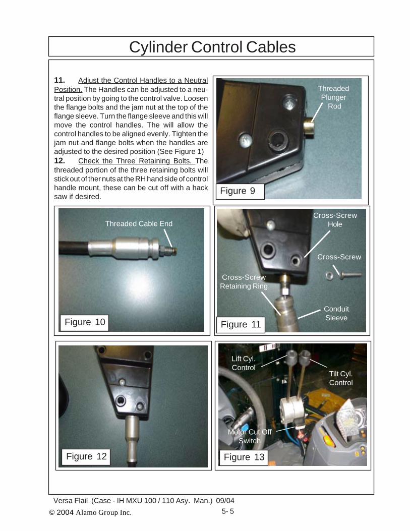
the cab floor. The cable control mounting bracketwill mount to the cab door post on the right handfront side. There are four threaded holes in thiscab door post. Hold the bracket up against thedoor post and determine the height that you wantthe control handles. Use the two holes that alignwith the bracket to mount it to the door post. (SeeFigure 7).5. Control Stick Assembly. Remove theCross- Screw from the bottom of the ControlStick Assembly. DO NOT remove the screwsthat fasten the two housings halves together(See Figure 8).6. Threaded Plunger Rod. While holding thehousing, fully shift the Handle in the Control StickAssembly to expose the female-threaded end ofthe Plunger Rod (See Figure 9).7. Threaded Cable End. While holding theHandle to expose the Plunger Rod, thread theThreaded Bead of the Cable into the end of thePlunger Rod and tighten securely. Release theHandle, allowing the Cable to pull into the ControlStick Assembly (See Figure 10).8. Attach Cable To Plunger. Once Cable isattached to Plunger Rod, slide the silver ConduitSleeve into the bottom of the Control Stick As-sembly and align the groove in the Conduit Sleevewith the Cross-Screw Hole (See Figure 11)9. Reinstall Cross - Screw. Install the Cross-Screw and tighten securely. Work the Handle tomake certain the cable is moving freely and notbinding (See Figure 12).10. Connect Control Stick to Cab Mount. Thecontrol Sticks will be mounted to the cab mount-ing bracket with three bolts. These same threebolts will also mount the motor cut off switchmounting bracket. First insert the three boltsthrough the control stick for the Lift Cylinderoperation. Second insert through the control stickfor Tilt Cylinder control. Third insert the Cut offSwitch mounting Bracket over the three bolts,The Motor cut off switch can be mounted elsewhere if wanted, mounting here is a recommen-dation (See Figure 13).
Figure 7
Cab Door Post Cable ControlHandle MountingBracket
Control StickAssembly
Cross-Screw
Figure 8
4. Install Cable Control Mount Bracket. Make certain that you mark the cables as to which iswhich on the control valve, this is important to make certain that the location will match the operatinginstruction decal. The Control Stick assembly can not be installed until the cables are run up through
Figure 6
© 2004 Alamo Group Inc. 5- 5Versa Flail (Case - IH MXU 100 / 110 Asy. Man.) 09/04
ThreadedPlunger
Rod
Threaded Cable EndCross-Screw
Hole
Figure 9
Figure 10
Cylinder Control Cables
Cross-Screw
ConduitSleeve
Cross-ScrewRetaining Ring
Figure 11
Figure 12 Figure 13
Lift Cyl.Control
Tilt Cyl.Control
Motor Cut OffSwitch
11. Adjust the Control Handles to a NeutralPosition. The Handles can be adjusted to a neu-tral position by going to the control valve. Loosenthe flange bolts and the jam nut at the top of theflange sleeve. Turn the flange sleeve and this willmove the control handles. The will allow thecontrol handles to be aligned evenly. Tighten thejam nut and flange bolts when the handles areadjusted to the desired position (See Figure 1)12. Check the Three Retaining Bolts. Thethreaded portion of the three retaining bolts willstick out of ther nuts at the RH hand side of controlhandle mount, these can be cut off with a hacksaw if desired.
© 2004 Alamo Group Inc. 5- 6Versa Flail (Case-IH MXU 100 / 110 Asy. Man.) 09/04
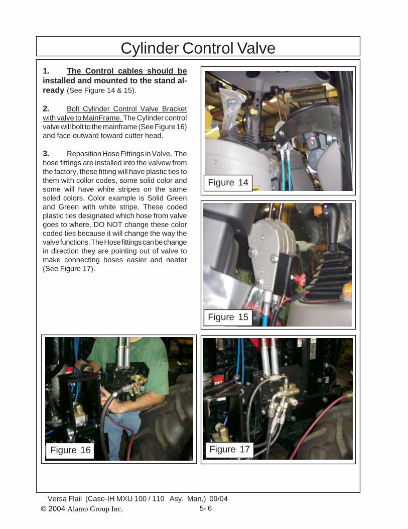
Cylinder Control Valve1. The Control cables should beinstalled and mounted to the stand al-ready (See Figure 14 & 15).
2. Bolt Cylinder Control Valve Bracketwith valve to MainFrame. The Cylinder controlvalve will bolt to the mainframe (See Figure 16)and face outward toward cutter head.
3. Reposition Hose Fittings in Valve. Thehose fittings are installed into the valvew fromthe factory, these fitting will have plastic ties tothem with collor codes, some solid color andsome will have white stripes on the samesoled colors. Color example is Solid Greenand Green with white stripe. These codedplastic ties designated which hose from valvegoes to where, DO NOT change these colorcoded ties because it will change the way thevalve functions. The Hose fittings can be changein direction they are pointing out of valve tomake connecting hoses easier and neater(See Figure 17).
Figure 14
Figure 15
Figure 16 Figure 17

© 2004 Alamo Group Inc. 5- 7Versa Flail (Case - IH MXU 100 / 110 Asy. Man.) 09/04
Starter Solenoid WireStarter Solenoid WireSwitched Power SupplyGround
Wiring Schematic
Fuse Holderwith Fuse
Push-Pull Switch
Connecters Shipped Loose inSeparate Plastic Bag
#16 Black(-)
Ring Connectorto Ground
# 12 Brown LineConnector toStarter Solenoid
#16 Red (+) toSwitched PowerSupply
Solenoid Connectorat Cutter Valve
# 12 Brn
# 16 Red# 16 Yellow
ON / OffSwitch Plug
SolenoidConnector
#16 Black
# 16 Yellow
#16 Black
Figure 14
© 2004 Alamo Group Inc. 5- 8Versa Flail (Case-IH MXU 100 / 110 Asy. Man.) 09/04
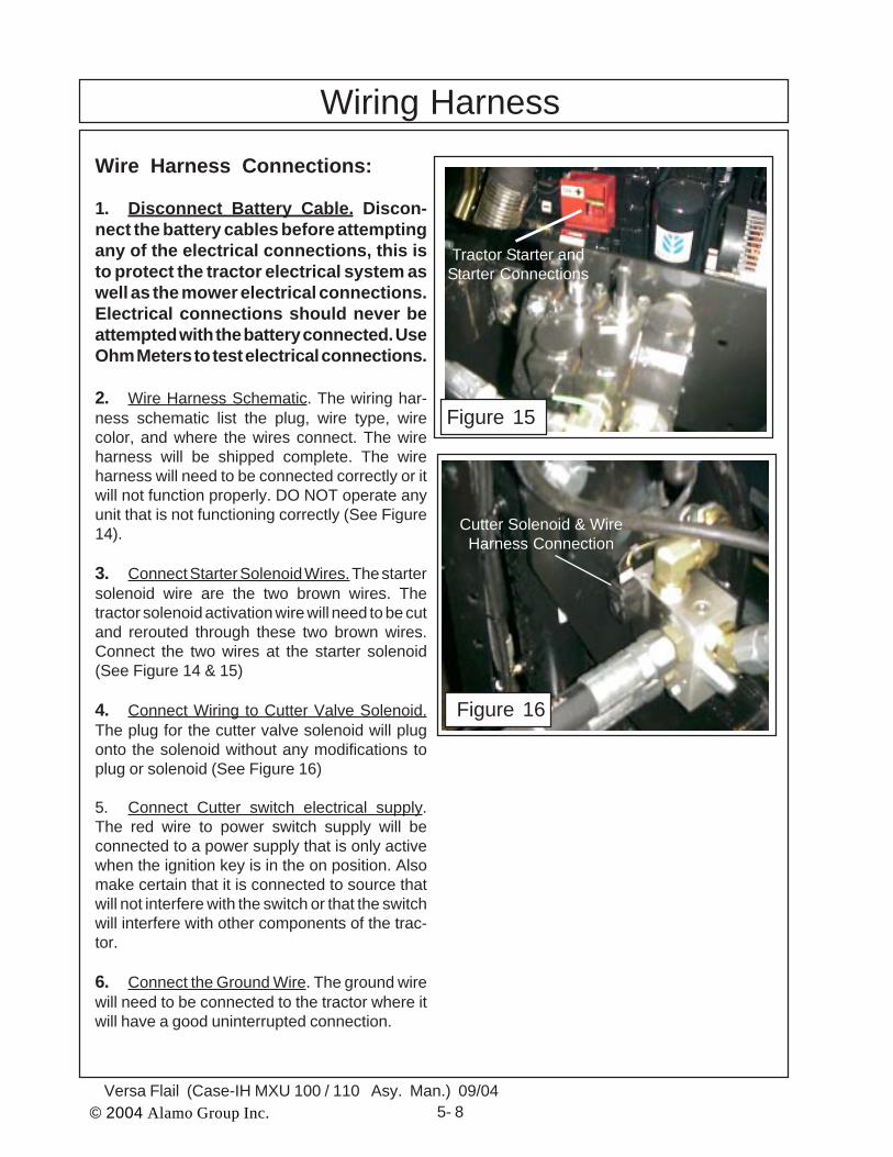
Wiring HarnessWire Harness Connections:
1. Disconnect Battery Cable. Discon-nect the battery cables before attemptingany of the electrical connections, this isto protect the tractor electrical system aswell as the mower electrical connections.Electrical connections should never beattempted with the battery connected. UseOhm Meters to test electrical connections.
2. Wire Harness Schematic. The wiring har-ness schematic list the plug, wire type, wirecolor, and where the wires connect. The wireharness will be shipped complete. The wireharness will need to be connected correctly or itwill not function properly. DO NOT operate anyunit that is not functioning correctly (See Figure14).
3. Connect Starter Solenoid Wires. The startersolenoid wire are the two brown wires. Thetractor solenoid activation wire will need to be cutand rerouted through these two brown wires.Connect the two wires at the starter solenoid(See Figure 14 & 15)
4. Connect Wiring to Cutter Valve Solenoid.The plug for the cutter valve solenoid will plugonto the solenoid without any modifications toplug or solenoid (See Figure 16)
5. Connect Cutter switch electrical supply.The red wire to power switch supply will beconnected to a power supply that is only activewhen the ignition key is in the on position. Alsomake certain that it is connected to source thatwill not interfere with the switch or that the switchwill interfere with other components of the trac-tor.
6. Connect the Ground Wire. The ground wirewill need to be connected to the tractor where itwill have a good uninterrupted connection.
Figure 15
Figure 16
Cutter Solenoid & WireHarness Connection
Tractor Starter andStarter Connections
© 2004 Alamo Group Inc. 6- 1Versa Flail (Case - IH MXU 100 / 110 Asy. Man.) 09/04
VERSA MOWERExhaust & Battery
Modification
Case -IH Tractor MXU 100 / 110 Cab/4wd
Section 6

© 2004 Alamo Group Inc. 6 - 2Versa Flail (Case-IH MXU 100 / 110 Asy. Man.) 09/04
Modify Exhaust on Tractor:
1. Modify Tractor Factory ExhaustSystem. The Exhaust of the tractor must bemodified to move exhaust (muffler) in closer tothe hood of tractor to give the Frame workclearance . This must be done before the frameis mounted.
2. Remove Old Exhaust System. The stockfactory muffler is removed first, this will besaved as it will be reused after the exhaust pipehas been changed.
3. Remove Existing Exhaust Pipe & Exist-ing Exhaust Mounting Bracket. There are boltsthat hold the exhaust flange to the engine ex-haust manifold, these will need to be removecompletely. There is a stock mounting bracketlocated at the outer corner of the cab thatsupports the exhaust pipe. This bracket will beremoved also. (See Figure 2). Lay the Bracketand exhaust pipe aside as the kit will includereplacement Pipe, Bracket and Fasteners.
4. Exhaust Relocation Kit. The new Ex-haust pipe, mount bracket, clamp and flangemounting bolt will be included in Exhaust Relo-cation Kit P/N 02980717
Part No. Qty Description02980649 1 Exhaust Brkt Wldmnt02980718 1 Turbo Down pipe Wldmnt02980584 2 3" Exhaust Clamp Kit02980727 4 Bolt, Skt Hd 8 mm X 35 mm02980728 5 Bolt, Hex Hd 12 mm X 30 mm701513C 5 Flat washer, 12 mm00754566 5 Lockwasher, 12 mm
5. Install Exhaust Pipe. The new Exhaustpipe will come as a welded assembly (P/N02980718) with a new flange and new bolts (P/N 02980727). Tighten the flange bolts that retainthe down pipe to the exhaust manifold (SeeFigure 2).
Exhaust & Battery Modification
Figure 1
Stock Exhaust PipeComponents
Figure 2
bolts forExhaust Flange
at Texhaustmanifold
Stock ExhaustMounting Bracketat corner of Cab
Small Pipealso connects to muffler
ReplacementExhaust MountAnd Exhaustclamps
Figure 3

© 2004 Alamo Group Inc. 6- 3Versa Flail (Case - IH MXU 100 / 110 Asy. Man.) 09/04
Figure 4
NewExhaustMntg Brktat cornerof Cab
Exhaust Mufflermoved inward from
stock location
Modify Exhaust on Tractor:(continued)
6. Install Exhaust Mount Bracket. The newExhaust mounting Bracket Weldment (SeeFigure 4 & 5 P/N 02980649) must be installed tomount the new Turbo Down pipe to using the 3"Clamp (P/N 02980584) to mount the Down pipethe new Exhaust mounting bracket. Note: TheNew Exhaust Bracket has slotted holes in it thatare not shown in the angle that figure 4 isshowing the weldment. There are 5 Bolts andlockwashers used to mount this weldment.
7. Reinstall Muffler. Reinstall the mufflerusing the existing hardware for the muffler. Turnthe tip of the muffler toward the LH side of tractoras shown in Figure 6 if it is not already. Mufflershould now be 8-1/2" inward from the stocklocation, this is a must for clearance of the frame. Note figure 6 shows thee high frame alreadyinstalled, this is for reference only as the versawill not have this type frame and is for illustrationonly.
8. Muffler Clearance. Make certain that thehoses, wiring and other components are nottouching the muffler. Make certain that all shieldsif any are replaced around muffler and exhaustpipe. On the case tractor there is a small line thatwill also connect to the muffler, make certain thisline is reconnected when the muffler is installed(See Figure 2). This small metal pipe runs fromthe bottom of the air cleaner to the muffler andwill have to be cut to fit new location of muffler.The easiest way is to cut the line and add anothersection of rubber hose to connect it back. Theamount of and where it is to be cut should bedetermined by installer and the section of hosewill need to be supplied local. (See Figures 5, 7& 8)
Figure 6
Exhaust & Battery Modification
NewExhaustMntg Brktat cornerof Cab
Figure 5Samall MetalTube To Muffler

© 2004 Alamo Group Inc. 6 - 4Versa Flail (Case-IH MXU 100 / 110 Asy. Man.) 09/04
Exhaust & Battery Modification
Modify Exhaust on Tractor:(continued)
9. Figure 4 and 5 Shows small tube fromAir cleaner to muffler. This tube to be cut andreinstalled using additional piece of rubberhose and two clamps. This additional hoseand clamps will need to obtained locally. Notall tractors will have this optional small run-ning from air cleaner to muffler on it. (SeeFigure 4 & 5).
Modify Battery Bracket and Tray:
1. Remove Battery Cover , Battery andBattery mounting Tray / Brackets. (SeeFigure 6 & 7) Use Battery relocation Kit P/N02981750) Remove the battery cover fromthe battery box. Remove the battery from thetray. Remove the tray and the mountingbracket. Replace the bracket with batteryrelocation component supplied. Reinstall thebattery and the battery components. Thebatter cables will have to run from the back upover the battery, the they are installed aroundthe front of the battery the cover will not fitback on properly. This will relocated the bat-tery for clearance reasons.
Figure 4
Small Metaltube con-nects tomufflerhere
Figure 5
Figure 6 Figure 7
© 2004 Alamo Group Inc. 7 - 1Versa Flail (Case - IH MXU 100 / 110 Asy. Man.) 09/04
VERSA FLAILOptional Heads
Case -IH Tractor MXU 100 / 110 Cab/4wd
Section 7
© 2004 Alamo Group Inc. 7 - 2Versa Flail (Case-IH MXU 100 / 110 Asy. Man.) 09/04
Figure 1
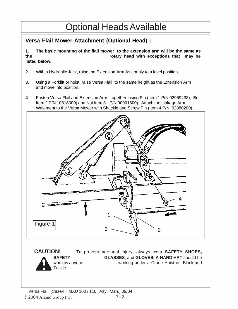
Optional Heads AvailableVersa Flail Mower Attachment (Optional Head) :
1. The basic mounting of the flail mower to the extension arm will be the same asthe rotary head with exceptions that may belisted below.
2. With a Hydraulic Jack, raise the Extension Arm Assembly to a level position.
3. Using a Forklift or hoist, raise Versa Flail to the same height as the Extension Armand move into position.
4. Fasten Versa Flail and Extension Arm together using Pin (Item 1 P/N 02959438), BoltItem 2 P/N 10318000) and Nut Item 3 P/N 00001800). Attach the Linkage ArmWeldment to the Versa Mower with Shackle and Screw Pin (Item 4 P/N 02880200).
CAUTION! To prevent personal injury, always wear SAFETY SHOES,SAFETY GLASSES, and GLOVES. A HARD HAT should beworn by anyone working under a Crane Hoist or Block-andTackle.
4
1
23
© 2004 Alamo Group Inc. 7 - 3Versa Flail (Case - IH MXU 100 / 110 Asy. Man.) 09/04
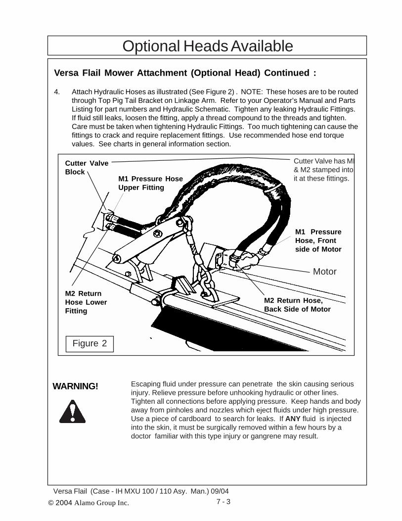
Optional Heads AvailableVersa Flail Mower Attachment (Optional Head) Continued :
4. Attach Hydraulic Hoses as illustrated (See Figure 2) . NOTE: These hoses are to be routedthrough Top Pig Tail Bracket on Linkage Arm. Refer to your Operator’s Manual and PartsListing for part numbers and Hydraulic Schematic. Tighten any leaking Hydraulic Fittings.If fluid still leaks, loosen the fitting, apply a thread compound to the threads and tighten.Care must be taken when tightening Hydraulic Fittings. Too much tightening can cause thefittings to crack and require replacement fittings. Use recommended hose end torquevalues. See charts in general information section.
Escaping fluid under pressure can penetrate the skin causing seriousinjury. Relieve pressure before unhooking hydraulic or other lines.Tighten all connections before applying pressure. Keep hands and bodyaway from pinholes and nozzles which eject fluids under high pressure.Use a piece of cardboard to search for leaks. If ANY fluid is injectedinto the skin, it must be surgically removed within a few hours by adoctor familiar with this type injury or gangrene may result.
M1 Pressure HoseUpper Fitting
M1 PressureHose, Frontside of Motor
Cutter ValveBlock
M2 ReturnHose LowerFitting
M2 Return Hose,Back Side of Motor
Motor
Figure 2
WARNING!
Cutter Valve has MI& M2 stamped intoit at these fittings.

© 2004 Alamo Group Inc. 7 - 4Versa Flail (Case-IH MXU 100 / 110 Asy. Man.) 09/04
Versa Ditcher Head Attachment (Optional Head) :
1. With a Hydraulic Jack, raise the Extension Arm Assembly to a level position.
2. Using a Forklift, raise Versa Ditcher to the same height as the Extension Arm and move intoposition.
3. Fasten Versa Ditcher and Extension Arm together using Pin (Item 1 P/N 02880700), Bolt(Item 2 P/N 10318000) and Nut (Item 3 P/N 00001800). Attach the Linkage Arm Weldmentto the Versa Ditcher with Shackle and Screw Pin (Item 4 P/N 02880200). (See Figure 3).
CAUTION! To prevent personal injury, always wear SAFETY SHOES, SAFETYGLASSES, and GLOVES. A HARD HAT should be worn by anyoneworking under a Crane Hoist or Block-and Tackle.
Optional Heads Available
Figure 3
1
2
3
4
© 2004 Alamo Group Inc. 7 - 5Versa Flail (Case - IH MXU 100 / 110 Asy. Man.) 09/04
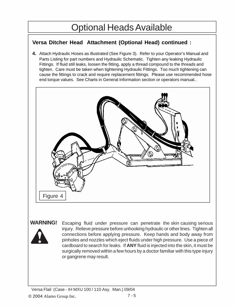
Optional Heads AvailableVersa Ditcher Head Attachment (Optional Head) continued :
4. Attach Hydraulic Hoses as illustrated (See Figure 3). Refer to your Operator’s Manual andParts Listing for part numbers and Hydraulic Schematic. Tighten any leaking HydraulicFittings. If fluid still leaks, loosen the fitting, apply a thread compound to the threads andtighten. Care must be taken when tightening Hydraulic Fittings. Too much tightening cancause the fittings to crack and require replacement fittings. Please use recommended hoseend torque values. See Charts in General Information section or operators manual..
Escaping fluid under pressure can penetrate the skin causing seriousinjury. Relieve pressure before unhooking hydraulic or other lines. Tighten allconnections before applying pressure. Keep hands and body away frompinholes and nozzles which eject fluids under high pressure. Use a piece ofcardboard to search for leaks. If ANY fluid is injected into the skin, it must besurgically removed within a few hours by a doctor familiar with this type injuryor gangrene may result.
WARNING!
Figure 4
© 2004 Alamo Group Inc. 7 - 6Versa Flail (Case-IH MXU 100 / 110 Asy. Man.) 09/04
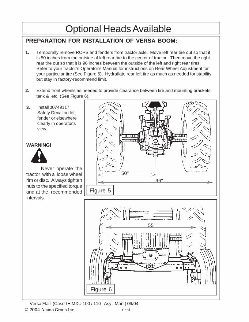
3. Install 00749117Safety Decal on leftfender or elsewhereclearly in operator'sview.
WARNING!
Never operate thetractor with a loose wheelrim or disc. Always tightennuts to the specified torqueand at the recommendedintervals.
PREPARATION FOR INSTALLATION OF VERSA BOOM:
1. Temporally remove ROPS and fenders from tractor axle. Move left rear tire out so that itis 50 inches from the outside of left rear tire to the center of tractor. Then move the rightrear tire out so that it is 96 inches between the outside of the left and right rear tires.Refer to your tractor’s Operator’s Manual for instructions on Rear Wheel Adjustment foryour particular tire (See Figure 5). Hydraflate rear left tire as much as needed for stabilitybut stay in factory-recommend limit.
2. Extend front wheels as needed to provide clearance between tire and mounting brackets,tank & etc. (See Figure 6).
Optional Heads Available
50"96"
55"
Figure 5
Figure 6

© 2004 Alamo Group Inc. 7 - 7Versa Flail (Case - IH MXU 100 / 110 Asy. Man.) 09/04
Optional Heads AvailablePREPARATION FOR INSTALLATION OF VERSA BOOM: (continued)
NOTE:If Versa Boom is being installed on a Versa Mower that is already in use, Extension Arm aswell as Mower Head must be removed.
1. With a forklift or hoist raise Boom Mount Weldment and slide into Basic Tractor MountWeldment. Insert pin into Boom Mount Weldment and Basic Tractor Mount Weldment.
To prevent pin from backing out, at-tach bolt and nut in pin. Bolt top flanges of Boom Mount Weldment to vertical cylin-der mount using hardware provided. Refer to your Installation Manual provided inyour mount kit for part numbers and quantities (See Figure 7).2. Fasten counterweight to Basic Tractor Mount Weldment with fasteners called out on the
Installation Manual (See Figure 8).
NOTE:When installing a Versa Boom, additional counterweight (wheel weights, calciumchloride in tires etc.) must be installed to insure stability and safe operation.
3. To install the Axle Mount Weldment, attach Cage Axle Mount Brackets to Axle MountWeldment with hardware provided in your Mount Kit. Attach Axle Mount Weldment andstrap to Axle Mount to Tractor Axle with Hardware provided. Level axle mount weldmentand weld to Boom Mount Weldment. Attach Valve Mount Weldment to Basic Tractor
Mount with hardware provided. Refer toyour Installation Drawing provided in your Mount Kit (See Figure 9).4. To attach Versa Boom Cage Weldment, first lower Cage on tractor with a forklift or crane.
Bolt Cage to Axle Mount using straps and hardware provided in your Mount Kit (See Figure10)
Figure 7 Figure 8

© 2004 Alamo Group Inc. 7 - 8Versa Flail (Case-IH MXU 100 / 110 Asy. Man.) 09/04
5. Attach Boom Rest to axle of tractor w/ fasteners found in your Mount Kit. Refer to your Insta-llation Drawing for part numbers and quantities(See Figure 11) Recommended torque chartfor proper torque of bolts located in General In-formation Section..
6. With a forklift or hoist, raise the BoomWeldment and lower onto theKing Post Turning Arm. Align the BoomWeldment and Turning Arm with an Align-ing Pin. Insert Main Pin Bolt (P/N02960837) into Boom Weldment and Turning
Arm. Attach 1-1/8" lockwasher (p/n 00748000)and 1-1/8" nut (p/n 02921700) to bolt and tightenwith a 1-11/16" wrench until Boom Plates firmlycontact King Post. DO NOT OVER-TIGHT- EN.(See Figure 13) Note: Additional support maybe needed at the end of the Boom to aid ininstallation.
Note: Hoses on 20', 22', & 23' Booms are shippedfolded back inside Boom. Hoses must be routed inthe end of Boom before installing Boom on the KingPost (See Figure 12)
Figure 9 Figure 10
Figure 11
Figure 13
Figure 12
Optional Heads Available

© 2004 Alamo Group Inc. 7 - 9Versa Flail (Case - IH MXU 100 / 110 Asy. Man.) 09/04
Optional Heads Available
8. The Swing Cylinder comes pre-assembled on the Mainframe. If it is a standard rear-swingBoom, the Swing Cylinder will be installed as in Figure 15. If it is a front swing Boom, theSwing Cylinder will be installed as in Figure 16. If the Cylinder is mounted incorrectly,reinstall in it's proper location.
7. Next, raise the Lift Cylinder under the Boom Weldment and attach to King Post Lug with bolt(P/N 00755076 for 17' A-Boom, P/N 00750479 for 20', 23', & 28' A-Boom), washer (P/N00749946), and nut (P/N 02030300). Make sure hydraulic fittings are facing towards the rearof the tractor. Attach rod end of Lift Cylinder to Boom Weldment with bolt (P/N 00750479),washer (P/N 00749946), and nut, (P/N 02030300) provided in your Mount Kit (See Figure14). Tighten until Locknut firmly contacts ears on Cylinder. DO NOT OVER-TIGHTEN.
Figure 14
Figure 15 Figure 16

© 2004 Alamo Group Inc. 7 - 10Versa Flail (Case-IH MXU 100 / 110 Asy. Man.) 09/04
FIGURE 66
9. X-Frame Square Head Attachment. With aforklift or hoist, lower the Boom Weldmentdown on the X-Frame Square Head. Alignthe Boom Weldment with the X-Frame
Square Head Hitch Post. Insert specialbolts (item 1 p/n 02956972 and item 2 p/n00752405) into Boom Weldment and HitchPost. Attach nuts (item 3 p/n 02030300and item 4 p/n 00037200) to bolt and
tighten securely. Note: Additional supportmay be needed at the end of the Boom toaid in installation (See Figure 17).
Figure 17
1,3
2,4
ATTACHMENT OF HYDRAULIC HOSES ON VERSA BOOM:
1. Attach the 1-1/4" Hoses from Solenoid Cutter Valve to Hydraulic Tubes on Boom.2. Attach the 1/4" Hoses from the Control Valve to Lift Cylinder.3. Attach the 1/2" Return Hoses from the Control Valve to the Pipe tee.4. Attach the 1/2" Pressure Hose form the Hydraulic Pump to the Control Valve.5. Attach the 1/4" Hoses from the Control Valve to the Swing Cylinder.6. Attach the 1/4" Hoses from the Control Valve to the Dipper and Tilt Cylinder.
Refer to your Operator’s Manual and Parts Listing for part numbers and pump driveshaft sectionof this manual for Hydraulic Schematic. Tighten any leaking Hydraulic Fittings. If fluid still leaks,loosen the fitting, apply a pipe thread compound to the threads and tighten. Care must be takenwhen tightening Hydraulic Fittings. Too much tightening can cause the fittings to crack andrequire replacement fittings. Use recommended hose end torque values. See torque chart ingeneral information section. (See Figure 18).
Figure 18
Optional Heads Available

© 2004 Alamo Group Inc. 7 - 11Versa Flail (Case - IH MXU 100 / 110 Asy. Man.) 09/04
ATTACHMENT OF HYDRAULIC HOSES ON VERSA BOOM: contin-ued
7. Attach the 1-1/4" Pressure Hose (item 1) and Return Hose (item 2) from the SolenoidCutter Valve (See Figure 19) to the Hydraulic Tubes onthe Versa Boom (See Figure 20). Use the recommended hose end torquevalues in general information section.8. Attach the 1/2" Return Hose (item 1) from Cutter Valve (See Figure 21) to the
Control Valve (See Figure 22). Use the recommended hose end torque values listed ingeneral information section.
Escaping fluid under pressure can penetrate the skin causing seriousinjury. Relieve pressure before unhooking hydraulic or other lines. Tightenall connections before applying pressure. Keep hands and body awayfrom pinholes and nozzles which eject fluids under high pressure. Use apiece of cardboard to search for leaks. If ANY fluid is injected into theskin, it must be surgically removed within a few hours by a doctor familiarwith this type injury or gangrene may result.
WARNING!
Optional Heads Available
1 Pressure ToMower
2 Return FromMower
1 PRESSURE
2 RETURN
Return toTank
Figure 19 Figure 20
1Figure 21 Figure 22

© 2004 Alamo Group Inc. 7 - 12Versa Flail (Case-IH MXU 100 / 110 Asy. Man.) 09/04
When working with or on the machine, take care and stay alert. Alwaysbe careful. Always be alert for hazards. Watch out for others.
WARNING!
ATTACHMENT OF HYDRAULIC HOSES ON VERSA BOOM: contin-ued
9. Attach the 1/2" Pressure Hose from the Hydraulic Pump (See Figure 23 ) to the ControlValve (See Figure 24). Use the recommended hose end torque values on page 37.
10. Attach the 1/4" Hoses (item 1 and 2) from the Control Valve (See Figure 25 ) to the SwingCylinder (See Figure 26). Use the recommended hose end torque values in generalinformation section..
Optional Heads Available
2
1
2 1
Figure 23
Figure 25 Figure 26
Figure 24
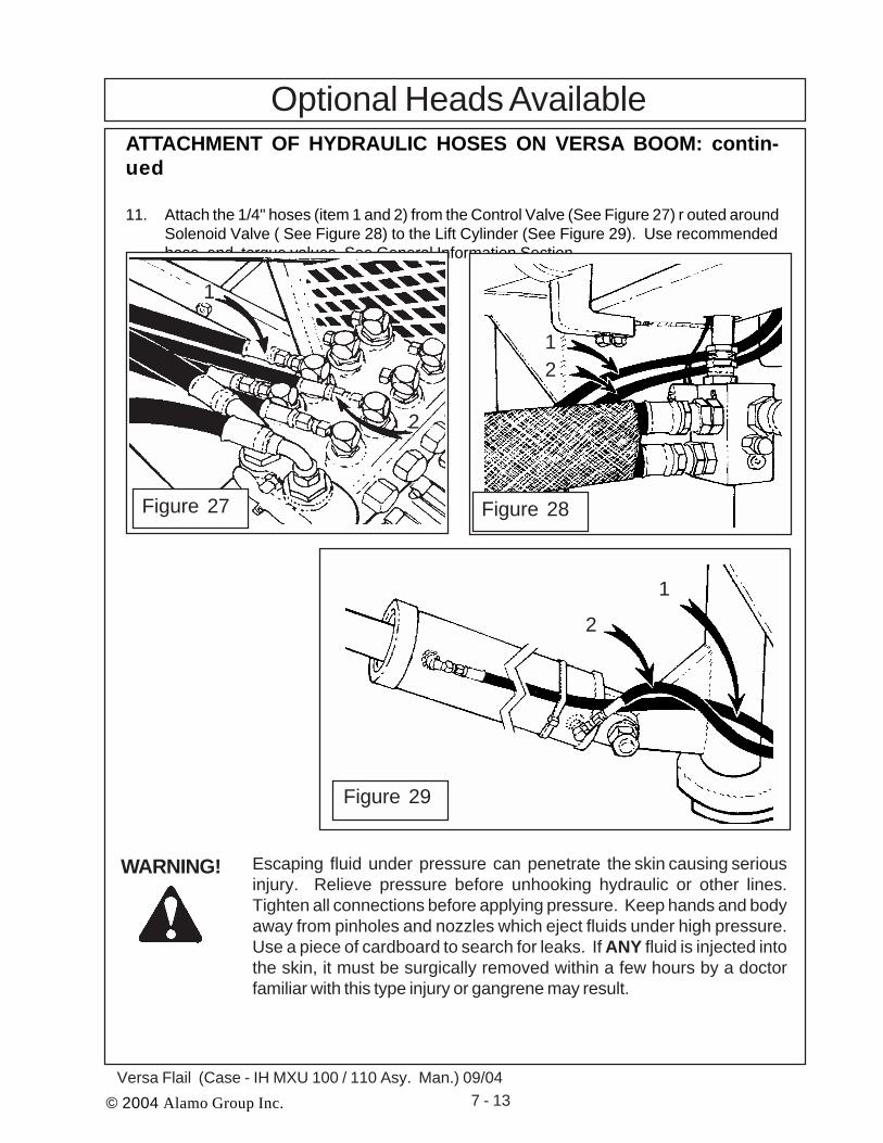
© 2004 Alamo Group Inc. 7 - 13Versa Flail (Case - IH MXU 100 / 110 Asy. Man.) 09/04
Optional Heads Available
Escaping fluid under pressure can penetrate the skin causing seriousinjury. Relieve pressure before unhooking hydraulic or other lines.Tighten all connections before applying pressure. Keep hands and bodyaway from pinholes and nozzles which eject fluids under high pressure.Use a piece of cardboard to search for leaks. If ANY fluid is injected intothe skin, it must be surgically removed within a few hours by a doctorfamiliar with this type injury or gangrene may result.
WARNING!
ATTACHMENT OF HYDRAULIC HOSES ON VERSA BOOM: contin-ued
11. Attach the 1/4" hoses (item 1 and 2) from the Control Valve (See Figure 27) r outed aroundSolenoid Valve ( See Figure 28) to the Lift Cylinder (See Figure 29). Use recommendedhose end torque values, See General Information Section
21
Figure 28
2
1
Figure 29
2
1
Figure 27

© 2004 Alamo Group Inc. 7 - 14Versa Flail (Case-IH MXU 100 / 110 Asy. Man.) 09/04
ATTACHMENT OF HYDRAULIC HOSES ON VERSA BOOM: contin-ued
6. Attach the Dipper Cylinder Hoses (item 1 and 2 See Figure 30) to the Control Valve (SeeFigure 31). Use the recommended hose end torque values, See Torque Charts inGeneral Information section.
7. Attach the Tilt Cylinder Hoses (item 1 and 2 See Figure 32) to the Control Valve (SeeFigure 33). Use the recommended hose end torque values , See Torque Charts inGeneral Information section..
Optional Heads Available
2 1 1
2
Figure 30 Figure 31
2
1
2
1
Figure 32 Figure 33
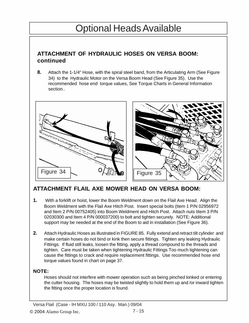
© 2004 Alamo Group Inc. 7 - 15Versa Flail (Case - IH MXU 100 / 110 Asy. Man.) 09/04
ATTACHMENT OF HYDRAULIC HOSES ON VERSA BOOM:continued
8. Attach the 1-1/4" Hose, with the spiral steel band, from the Articulating Arm (See Figure34) to the Hydraulic Motor on the Versa Boom Head (See Figure 35). Use therecommended hose end torque values, See Torque Charts in General Informationsection..
Optional Heads Available
Figure 34 Figure 35
ATTACHMENT FLAIL AXE MOWER HEAD ON VERSA BOOM:
1. With a forklift or hoist, lower the Boom Weldment down on the Flail Axe Head. Align theBoom Weldment with the Flail Axe Hitch Post. Insert special bolts (Item 1 P/N 02956972and Item 2 P/N 00752405) into Boom Weldment and Hitch Post. Attach nuts Iitem 3 P/N02030300 and Item 4 P/N 000037200) to bolt and tighten securely. NOTE: Additionalsupport may be needed at the end of the Boom to aid in installation (See Figure 36).
2. Attach Hydraulic Hoses as illustrated in FIGURE 85. Fully extend and retract tilt cylinder andmake certain hoses do not bind or kink then secure fittings. Tighten any leaking HydraulicFittings. If fluid still leaks, loosen the fitting, apply a thread compound to the threads andtighten. Care must be taken when tightening Hydraulic Fittings Too much tightening cancause the fittings to crack and require replacement fittings. Use recommended hose endtorque values found in chart on page 37.
NOTE:Hoses should not interfere with mower operation such as being pinched kinked or enteringthe cutter housing. The hoses may be twisted slightly to hold them up and /or inward tightenthe fitting once the proper location is found.
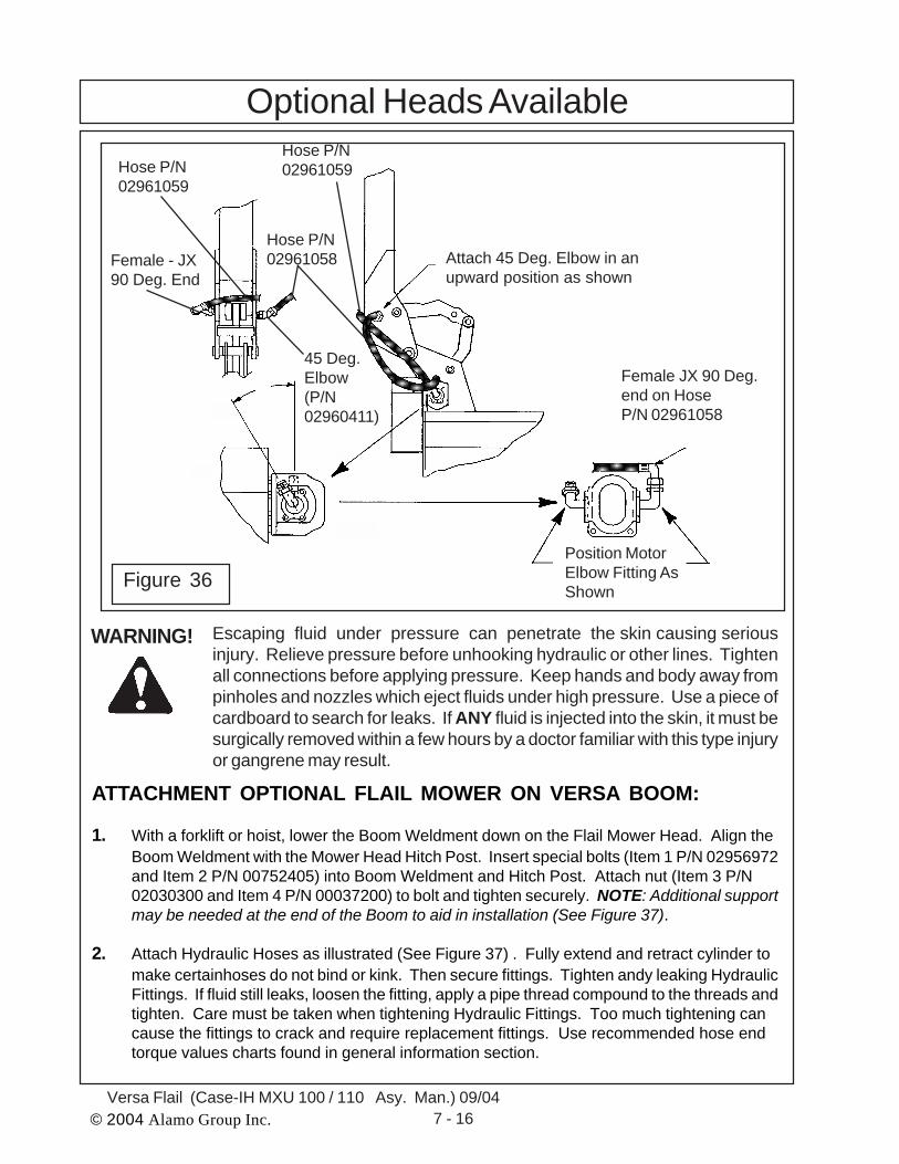
© 2004 Alamo Group Inc. 7 - 16Versa Flail (Case-IH MXU 100 / 110 Asy. Man.) 09/04
Escaping fluid under pressure can penetrate the skin causing seriousinjury. Relieve pressure before unhooking hydraulic or other lines. Tightenall connections before applying pressure. Keep hands and body away frompinholes and nozzles which eject fluids under high pressure. Use a piece ofcardboard to search for leaks. If ANY fluid is injected into the skin, it must besurgically removed within a few hours by a doctor familiar with this type injuryor gangrene may result.
WARNING!
Optional Heads Available
Figure 36
Female - JX90 Deg. End
Hose P/N02961059
45 Deg.Elbow(P/N02960411)
Hose P/N02961058 Attach 45 Deg. Elbow in an
upward position as shown
Female JX 90 Deg.end on HoseP/N 02961058
Position MotorElbow Fitting AsShown
Hose P/N02961059
ATTACHMENT OPTIONAL FLAIL MOWER ON VERSA BOOM:
1. With a forklift or hoist, lower the Boom Weldment down on the Flail Mower Head. Align theBoom Weldment with the Mower Head Hitch Post. Insert special bolts (Item 1 P/N 02956972and Item 2 P/N 00752405) into Boom Weldment and Hitch Post. Attach nut (Item 3 P/N02030300 and Item 4 P/N 00037200) to bolt and tighten securely. NOTE: Additional supportmay be needed at the end of the Boom to aid in installation (See Figure 37).
2. Attach Hydraulic Hoses as illustrated (See Figure 37) . Fully extend and retract cylinder tomake certainhoses do not bind or kink. Then secure fittings. Tighten andy leaking HydraulicFittings. If fluid still leaks, loosen the fitting, apply a pipe thread compound to the threads andtighten. Care must be taken when tightening Hydraulic Fittings. Too much tightening cancause the fittings to crack and require replacement fittings. Use recommended hose endtorque values charts found in general information section.

© 2004 Alamo Group Inc. 7 - 17Versa Flail (Case - IH MXU 100 / 110 Asy. Man.) 09/04
NOTE:Hoses should not interfere with flail opera-tion such as being pinched kinked or enter-ing the cutter housing. Hoses may betwisted slightly too hold them up or inward.Tighten fitting once proper location is found.
Escaping fluid under pressurecan penetrate the skin causingserious injury. Relieve pressurebefore unhooking hydraulic orother lines. Tighten all connec-tions before applying pressure.Keep hands and body away frompinholes and
WARNING!1,3
2,4
nozzles which eject fluids under high pressure. Use a piece of cardboard tosearch for leaks. If ANY fluid is injected into the skin, it must be surgicallyremoved within a few hours by a doctor familiar with this type injury or gan-grene may result.
Figure 37
ATTACHMENT OPTIONAL FLAIL MOWER ON VERSA BOOM:
1. With a forklift or hoist, lower the Boom Weldment down in the Ditcher Head. Align the BoomWeldment with the Ditcher Head Hitch Post together. Insert special pins p/n 02958929 intoBoom Weldment and Hitch Post. Attach with washer P/N 00749185 and roll pin P/N00610600. NOTE: Additional support may be needed at the end of the Boom to aid ininstallation (See Figure 38).
2. Attach Hydraulic Hoses as illustrated (See Figure 38). Tighten any Hydraulic Fittings. If fluidstill leaks, loosen the fitting, apply a pipe thread compound to the threads and tighten. Caremust be taken when tightening Hydraulic Fittings. Too much tightening can cause the fittingsto crack and require replacement. Use recommended hose end torque values found in thegeneral information section.
Note:The two hoses connecting the main boomto dipper arm are used to connect theVersa Ditcher motor. The 90 degree fittings attach to the fittings on the main boomand the straight fittings attach to the 90degree fittings on the hydraulic motor.
SeeNote
Figure 38
Optional Heads Available

© 2004 Alamo Group Inc. 7 - 18Versa Flail (Case-IH MXU 100 / 110 Asy. Man.) 09/04
ATTACHMENT OPTIONAL TIMBER CAT HEAD ON VERSA BOOM:
1. Attach the Timber Cat Head to the boom using the pins included with the head. Be carefulnot to damage the pivot bushings in the boom when inserting the pins. Attach the 90°elbow (Item 1) to the front port of the boom and position it so that it faces down. Attach the90° end of the return hose (P/N 02973125) to the fitting and attach the straight end to the90° fitting (Item 2) on the flow divider (if it is not already connected). Attach the pressurehose (P/N 02973124) to the rear port of the boom and attach the other end to the 90°elbow (Item 3) on the flow divider (if it is not already attached). (See Figure 39). Be surethe hoses are routed as shown in the figure and securly tighten all connections. Starttractor and move the head tilt through its motions and check for excessive twisting andbending. It may require many attempts to obtain the optimum hose connection position.
Escaping fluid under pressure can penetrate the skin causing seriousinjury. Relieve pressure before unhooking hydraulic or other lines. Tighten allconnections before applying pressure. Keep hands and body away frompinholes and nozzles which eject fluids under high pressure. Use a piece ofcardboard to search for leaks. If ANY fluid is injected into the skin, it must besurgically removed within a few hours by a doctor familiar with this type injuryor gangrene may result.
Optional Heads Available
WARNING!
BoomPressureHose
ReturnHose
1
2
3
Flow Divider
2 Once Hose position is achie-ved, start the tractor and po-sition the head in a safe areafor operation, if necessary,baracade the head to preventany contact while it is beingoperated. This unit is dan-gerous - STAY AWAY - anytime the tractor is in opera-tion! Turn on the head andbring the tractor engine up tonormal operating speed (540PTO RPM). Tighten any leak-ing hydraulic fittings. Caution,too much tightening cancause the fittings to crack andrequire replacement. Userecommended hose endtorque valves found in theMaintenance Section.
Figure 39
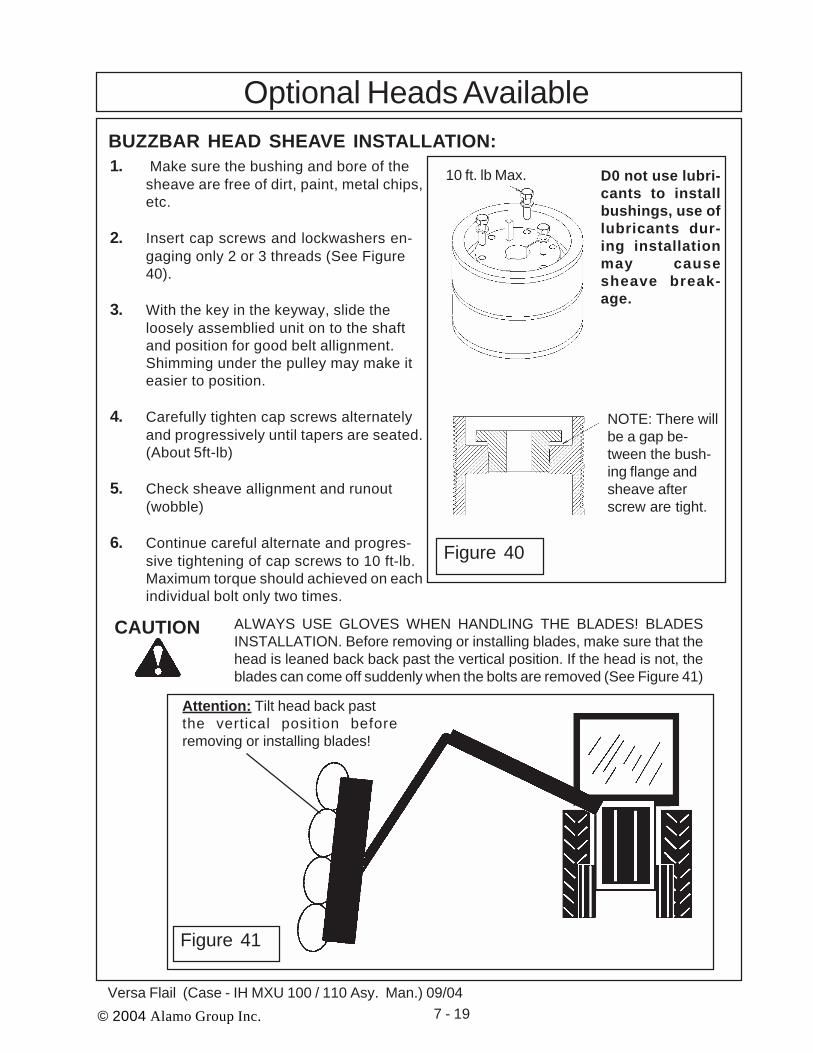
© 2004 Alamo Group Inc. 7 - 19Versa Flail (Case - IH MXU 100 / 110 Asy. Man.) 09/04
1. Make sure the bushing and bore of thesheave are free of dirt, paint, metal chips,etc.
2. Insert cap screws and lockwashers en-gaging only 2 or 3 threads (See Figure40).
3. With the key in the keyway, slide theloosely assemblied unit on to the shaftand position for good belt allignment.Shimming under the pulley may make iteasier to position.
4. Carefully tighten cap screws alternatelyand progressively until tapers are seated.(About 5ft-lb)
5. Check sheave allignment and runout(wobble)
6. Continue careful alternate and progres-sive tightening of cap screws to 10 ft-lb.Maximum torque should achieved on eachindividual bolt only two times.
CAUTION ALWAYS USE GLOVES WHEN HANDLING THE BLADES! BLADESINSTALLATION. Before removing or installing blades, make sure that thehead is leaned back back past the vertical position. If the head is not, theblades can come off suddenly when the bolts are removed (See Figure 41)
BUZZBAR HEAD SHEAVE INSTALLATION:
D0 not use lubri-cants to installbushings, use oflubricants dur-ing installationmay causesheave break-age.
Optional Heads Available
10 ft. lb Max.
NOTE: There willbe a gap be-tween the bush-ing flange andsheave afterscrew are tight.
Figure 40
Attention: Tilt head back pastthe vertical position beforeremoving or installing blades!
Figure 41

© 2004 Alamo Group Inc. 7 - 20Versa Flail (Case-IH MXU 100 / 110 Asy. Man.) 09/04
NOTES
© 2004 Alamo Group Inc. 8- 1Versa Flail (Case - IH MXU 100 / 110 Asy. Man.) 09/04
VERSA MOWERFilling Hydraulic System
AndInitial Start up Instructions
Case -IH Tractor MXU 100 / 110 Cab/4wd
Section 8

© 2004 Alamo Group Inc. 8 - 2Versa Flail (Case-IH MXU 100 / 110 Asy. Man.) 09/04
Figure 2
Filling Hydraulic SystemCheck Attchment of Hydraulic Hoses:WARNING! Once pumps are installed, DO NOT start the tractor (which will turn the
pumps) unless the hydraulic circuits are completed and filled with the specifiedUniversal Tractor Hydraulic oil and the pump has been primed. Running pumpswithout oil will cause non-warrant-able damage.
It is important that pipe thread sealant be used only on pipe threads; never on connections or onstraight thread "O" ring fittings. Use the pipe thread sealant liquid only. Do not substitute withsome other type of sealant, such as, teflon tape, paint, shellac, etc.
Hoses supplied have two types of fittings; solid or swivel. Some hoses have solid fittings on bothends; others have a solid fitting and a swivel fitting. Hoses with two solid fittings will fit into either ainternal solid thread or a swivel adapter union. When installing either type hose, solid fittings mustbe installed first, then install the swivel end of the hose or fitting.The Versa hydraulic system incorporates three basic types of hydraulic fittings:A. Standard pipe (NPT or NPTF) thread fittings.
This type requires a small amount of evenly-applied sealant.
B. Swivel fittings. This type does not require anysealant on the swivel end because it sealsagainst an internal flare.C. "O" Ring fittings. This type does not require any
sealant on the "O" Ring end of the fitting.It is extremely important to avoid getting pipe threadsealant inside the fittings or hoses. KEEP THE INTE-RIOR OF ALL HYDRAULIC COMPONENTS CLEAN.Inspect the inside diameter of each hose before as-sembly. Make certain that no obstruction is present.Dirt, sand, dust, etc., are abrasive and once in thesystem can cause immediate or early failure.
When assembling the fittings and hoses, be carefulnot to introduce any dust or contaminants into thesystem. Keep all fittings, hoses, and hydrauliccomponents sealed until installed. Do not allow anycomponents to lie open and exposed to dust orcontamination. Do not lay parts down on the dirt orsand and then assemble them as this will introducecontaminants into the system.
CAUTION! To avoid Hydraulic Contamination, always keep all hoses and hydraulic fit-tings capped until they are ready to beinstalled (See Figure 1 & 2).
Figure 1

© 2004 Alamo Group Inc. 8- 3Versa Flail (Case - IH MXU 100 / 110 Asy. Man.) 09/04
Filling Hydraulic System
Fill Hydraulic System With Oil:
1. Remove the Filler Cap Weldment. It willbe easier to unscrew the filler neck weldmentto fill the hydraulic tank (See Figure 3).
2. Avoid Hydraulic Contamination is Im-portant. Avoid hydraulic contamination by filter-ing the hydraulic oil while filling the hydraulictank. Filter buggies or carts are commerciallyavailable for hydraulic system clean-up.These consist of a high-efficiency, high-ca-pacity filter, a circulating pump, a drive motor,and hoses for connecting to the overhauledmachine's hydraulic system (See Figure 4 &5).
3. When adding hydraulic oil, use onlynew oil from a sealed barrel. Used oil or oilfrom an open barrel may contain high levels ofcontamination. Transfer the oil into the hydrau-lic tank by using a hydraulic filter pump unitequipped with a properly operating 10 micronfilter. This will insure that the oil being added isclean. Do not just pour the oil directly into thehydraulic tank since most oils (even from asealed barrel) have contaminants that must beremoved, before operating the hydraulic sys-tem (See Figure 4, 5 & 6).
Figure 5 Figure 6
Figure 3
Figure 4

© 2004 Alamo Group Inc. 8 - 4Versa Flail (Case-IH MXU 100 / 110 Asy. Man.) 09/04
Filling Hydraulic SystemReturn Pressure Guage
Oil LevelSightGuage
4. Fill Hydraulic Tank to Sight Guage. Fillthe Hydraulic Reservoir until the fluid is visiblethrough the sight guage (See Figure 7)
5. Fill Suction Hose with Oil. To Preventthe pump from a dry start up remove thesuction hose at the tank, this clamp shouldhave been left loose from earlier (See Figure6). Fill the Suction Hose with hydraulic fluid sothat the oil will run down into the pump, andreinstall on Hydraulic Tank. Tighten hoseclamp securely (See Figure 8 & 9)
6. When Hydraulic Tank Is Full. Whenthe hydraulic tank has been filled and themower unit properly assembled, the unitshould be started up. NOTE: Make sure thatno materials, tools, or jacks have been leftunder the mower head. Make sure the frontand rear of the mower are properly guardedto prevent any foreign objects from beingthrown by the mower. All other workersshould keep a safe distance from the unitbefore the mower is started.
7. IMPORTANT: Change the return fil-ter in tank and suction filters after the first 200hours of operation. Change the filters againat 700 hours; then, change the oil and filtersat 1600 hours. After that, continue to changethe filter every 800 hours and the oil every1600 hours. Hydraulic oil to be used is Uni-versal Tractor Hydraulic . Use the aboveprocedures as part of a good filter mainte-nance program.
8. Monitor Oil Condition. Between filterchanges, monitor condition of filter by readingPressure Gauge mounted on filter on top ofthe Tank (See Figure 7). If pressure reads 15psi or greater at 1800 RPM engine speed andnormal operating temperature (140 deg. F. orgreater), filter element should be changed.Pressure gauges are color-coded to help in-dicate when to change element.
Figure 7
Figure 8
Figure 9

© 2004 Alamo Group Inc. 8- 5Versa Flail (Case - IH MXU 100 / 110 Asy. Man.) 09/04
Initial Start-Up ProcedureINITIAL START-UP PROCEDURE:1. Check all nuts and hex head bolts to ensure all are tight and all lock washers are fully
compressed (flattened).
2. Check all hoses and hydraulic connections. Make certain they are securely tightened. Refer tohose fitting tightening specification in the general information section.
3. Inspect all moving parts and make certain that no wires or hoses will be caught or pinchedwhen the tractor or the mower is in operation. Tie down loose wires and hoses.
4. Thoroughly grease all the lubrication points and install a lubricap on each grease fitting. Referto the Operation and Maintenance Section of the operators Manual for grease fitting locations.
5. Jack front of tractor up enough to allow axle to pivot through its full range. Whileturning wheels through their limits, right and left, swing them up and down. Look for
interference between tires and any part of the mower or frame components. If interfer-ence occurs, shims (not furnished) must be welded to axle pivot stop or steering arm to limitthe movement enough to avoid interference. Tractors with an adjustable front axle mayrequire an outward or inward adjustment of the wheels.
6. To fill the hydraulic reservoir with new, clean hydraulic oil, follow the steps below. Referto the Operation and Maintenance Section for specifications. (See Figure 10)
A. Avoid hyd. contamination by filtering the hyd. oil while filling the hyd. tank.B. Filter buggies or carts are commercially available for hydraulic system cleanup. These
consist of a high-efficiency, high-capacity filter, a circulating pump, a drive motor, andhoses for connecting the overhauled machine’s hydraulic system.
7. After the frame and mower is completely assembled to the tractor and with the mowerhead on the ground, fill the mower hydraulic tank above the oil level sight gaugeapproximately 5" or 1" below the top of the tank.
8. With mower ON/OFF switches in “ON” posi- tion & tractor fuelcut off, crank engine for 30 to 45 sec-onds to push oil to the pump and mo-tor. Check the oil level in the sight gauge.If no oil is seen add oil to bring the level up
to the sight gauge. NOTE: Do not fill the tankwith oil above level of sight gauge. Over fillingtank with oil after the initial filling may resultin oil being discharged through the air filter ontop of the hyd. tank. Start the tractor and
run it for 2 minutes and turn it off.Again check the oil level in thesight gauge. If the oil level is in t h esight gauge, the unit is ready to run. If nooil seen, add oil to bring the level up tothe sight gauge.
Figure 10

© 2004 Alamo Group Inc. 8 - 6Versa Flail (Case-IH MXU 100 / 110 Asy. Man.) 09/04
DO NOT leave unit unattended, and COMPLY WITH ALL WARNING DECALS.
If unit starts to make unusual noise, stop unit and check oil level. Also check forfrothy oil which would indicate a leak on suction side of system.
ROTATING KNIVES!Remove all foreign objects and stand clear of cutter units. DO NOTGET NEAR!NOTE: On tractor hydraulic powered circuit only, make certain that there is full
flow from tractor hydraulic system to control valve. Refer to tractor manual.
11. Read and fill out customer pre-delivery check list on following page. Go over these detailswith the customer and operators before delivery the unit is recommended. Shoe theoperator where all lubrication points are. Where the Oil level is checked. the safety decalslocated on the unit and the operational decals. Operator should be completely familiarwith the unit before operating it.
Initial Start-Up Procedure
CAUTION:
CAUTION:
9. After hydraulic system is fully charged and functioning properly, switch cutter units on, then speed engine up to 540 RPM PTO speed. Maintain this speed for about 5minutes. Check complete mower assembled components, look for any leaks, looseconnections, or anything that could cause premature wear or failure.
10. FINAL CHECK: Run Mower for about 1/2 hour at full speed. Check for leaks andvibrations. Frequently check oil temperature. Make certain it does not exceed 180 deg.NOTE: When raising wings, make certain there is no interference with mower,frame, cylinders or tractor. Lift wings slowly.

© 2004 Alamo Group Inc. 8- 7Versa Flail (Case - IH MXU 100 / 110 Asy. Man.) 09/04
1. ____ Is oil level in the tank even with the sight gauge on the tank?
2. ____ Has the proper oil been used in the system? Proper oil is Universal Tractor Hyd. Oil.
3. ____ Boom machine movement matches operation decal - Swing, Lift, Dipper, & Tilt?
4. ____ Is control valve and auxiliary control cables free and not stick?
5. ____ Are all hoses tight and do not leak? See hose fitting torque chart in general
information section.
6. ____ Are all decals in place? See operators manual for decal description and placement.
7. ____ Does tractor pass Alamo Industrials Mower Stability Test? Proper weights added?
8. ____ Have all grease points been adequately greased?
9. ____ Are all bolts tight? See bolt torque chart in the general information section.
10. ____ Have all hoses been properly routed so that hoses do not kink or bind when boom
is articulated through all motions?
11. ____ Does starter lockout device work correctly on machine? Tractor should not start if
mower switch is on.
12. ____ Is swing cylinder pinned in correct hole? On rear swing type machine, cylinder
should be pinned to outside hole. On front swing type machine, cylinder should be
pinned in inside hole.
13. ____ Is machine equipped w/ proper operator protection? Must have cage or cage
panels.
14. ____ Does mower operate when on/off switch is operated?
15. ____ Is head rotation correct? On rotary heads (looking from the top of the deck) rotation
should be clockwise so that debris will be thrown away from the tractor. On flails,
rotation can be forward or reverse, but forward rotation is standard.
16. ____ If operating a square head, are spindle housing bolts tight? Is spindle assembly
tight? Are bolts that hold blade bar to spindle tight?
17. ____ Does head operate smoothly at normal operating speed? Head should not vibrate
excessively .
All the above items should be checked off before delivery of mower unit to customer & operator.
Customer Pre-Delivery Check List.

© 2004 Alamo Group Inc. 8 - 8Versa Flail (Case-IH MXU 100 / 110 Asy. Man.) 09/04
NOTES
© 2004 Alamo Group Inc. 9- 1Versa Flail (Case-IH MXU 100 / 110 Asy. Man.) 09/04
VERSA FLAILMounting Specifications
Case -IH Tractor MXU 100 / 110 Cab/4wd
Section 9

© 2004 Alamo Group Inc. 9- 2Versa Flail (Case-IH MXU 100 / 110 Asy. Man.) 09/04
Case-IH MXU-100/110 Cab/4wd As Of : 9-04Max front tire: 13.6-24 (Radial)Max rear tire: 16.9-34 (Radial)Versa Mount Kit ……………………………………….........02981497Options:Lexan Window Kit ………………………………………….........02980888Side Screen Kit ………………………………………………...... 02980642Pump Guard Kit …………………………………………….........02980652Hydro 60/72 Mount Kit ………………………………………...... 02980830Extra Versa Installation Manual ………………………………..... 02981763
Restrictions:(1) In order to clear the front 4wd tires, the Versa frame must be positioned beside the platform resulting inthe removal of the right hand steps. Ingress/egress on the right is otherwise blocked by the control stand.This frame position unfortunately causes overwidth transport (~126" with Versa flail & max tire sizeslisted above).(2) The rear tires must be set at a full spread to allow enough clearance for the oil reservoir which is locatedbelow the left rear fender (See Figure 1).(3) Effective January 12, 2004, Case-New Holland began providing loader brackets as standard equipmentwith this tractor series. These brackets must be removed for proper Versa frame mounting. Plan at leastan extra hour or two to complete the removal.(4) This kit includes a battery relocation bracket which shifts the battery up and back at an angle. (SeeFigure 2) Furthermore, as a result of the Versa frame position, the battery box will no longer hinge outward.However, the battery can still be accessed and even removed with the assistance of one additional person.(5) Also included is exhaust modification kit #02980717 which allows the vertical A-post style exhaust to bemoved in approximately 8 1/2". This in turn allows the Versa frame to be installed closer to the centerline ofthe tractor.(6) A Neapco style driveline with double U-joints is utilized for this kit. An additional hole must be drilledthrough the cast “rib” of the front bolster just below the radiator in order to install the driveline half whichfastens to the crankshaft pulley. This process takes forty five minutes to an hour and should not affect thestructural integrity of the bolster.(7) The Neapco driveline kit includes a pump box which shifts the hydraulic pump approximately 6 1/4"forward. Though it is structurally sound, Engineering recommends the use of a pump guard to protect yourinvestment.(8) Optional wheel weight kits are designed to fit flanged rims only. Other rim styles may require a wheelweight adapter to be provided at the dealer/customer’s expense.(9) Lexan window insert #02966458 can not be installed with the side screen kit due to the extreme curvatureof the glass door.(10) The Versa frame and stabilizer have been designed to provide a minimum of 13" of ground clearanceon tractors equipped with 16.9-34 rear tires.(11)The Lexan window kit option is comprised of a molded piece of General Electric brand 3/8" Lexanwith a scratch resistant coating on both sides. It has been designed as a replacement for the standardright hand, tempered glass door that comes equipped with the tractors.
First Cut w/Long Extension Arm (Short Ext. Arm is Not Optional)Rotary: ~68 3/4" (Notice: HY60/72 will not have enough overlap!)Flail: ~70 1/2" (SHD96 OR 30.5" => 8" Overlap)
Mount Restrictions

© 2004 Alamo Group Inc. 9- 3Versa Flail (Case-IH MXU 100 / 110 Asy. Man.) 09/04
Figure 1: Under-Fender Oil Reservoir Figure 2: Battery Relocation
Figure 3: Motor Hose must be turned as shown Figure 4: Cutter Valve Relocation Bracket must be used
Figure 5: Tractor Exhaust Must Be Modified Figure 6: Tractor is 4 Wheel Drive
Mount Restrictions

© 2004 Alamo Group Inc. 9- 4Versa Flail (Case-IH MXU 100 / 110 Asy. Man.) 09/04
IMPORTANT NOTICE: The following Part / Assembly Numbers are for reference and shouldnot be ordered as replacement parts, unless all the components in that assembly are wanted.These will break down to bills of material of the components. Some of numbers listed are NOTindividual Parts but complete assemblies and/or box of assemblies. Check before ordering.
02981497 Versa Mount Kit : Consist of the Following 3 Asy No.Asy. No. Qty Description Qty02980869 1 ASY VERSA TANK UNDER FENDER (See Below BOM)02981498 1 COMP. BOX, CASE-IH MX100/110U V/M (See Below BOM)02981723 1 STABILIZER, CASE-IH MX100/110UThese Three items are included in Versa Mount Kit P/N 02981497
02981498 Component Box: Consist of the following Item No.
Item No. Qty Description000859 10 TIE, PLASTIC02026200 2 HOSE CLAMP, 1-5/16” TO 2-1/ 402879100 1 MOUNT-STABILIZER BAR02960409 2 ADAPTER, TUBE, ELBOW02961098 1 ADP HYD ELBOW 20MB -20MJ 9002961826 1 FRONT PUMP ASY-TANDEM,1-1/4 CAST02966873 1 DWG INST BOOT02966874 1 BOOT,CABLE02971199 2 CABLE, REMOTE CONTROL - 10202973712A 1 ASY DRIVELINE 7/8-13 SPLINE02978816 2 PLATE VERSA WELD-ON02959770 7 HOSE SUPPORT RING02980719 1 ASY., TS-A PUMP MOUNT W/COVER02980726 1 KIT, NH TS-A CONTROL STAND02980699 1 PULLEY ADAPTER NH TS-A02978281 2 WLDMT, HOSE RING02981499 1 BOLT BAG, CASE-IH MX100/110U VM02972560 1 HOSE SUCTION #24 -180LG02980717 1 KIT EXHAUST RELOCATION02981337 1 HOSE #20-20FJX -20FJX 150LG02981218 1 FRONT MOUNT PLATE LH.02981219 1 FRONT MOUNT PLATE RH.02981331 1 BRACKET, TANK TO AXLE02981750 1 KIT, BATTERY RELOCATION02981518 2 REAR MOUNT PLATE02980990 1 BRACKET, CUTTER VALVE RELOCATE02960407 2 ADP HYD ELBOW 20MJ -20FJX 9002981761 1 HOSE #20-20FJX -20FJX 73LG02960004 1 HOSE #8 - 8FJX - 8FJX90 92LG02961825 1 HYD ADP ELBOW 20MB -20MJ 4502981763 1 MANUAL, INST-CASE-IH MX-U VERSAComponent Box is included in Versa Mount Kit P/N 02981497
Mount Kit Components

© 2004 Alamo Group Inc. 9- 5Versa Flail (Case-IH MXU 100 / 110 Asy. Man.) 09/04
02980869 Tank Asy, Under Fender: Includes Following Item No.
Item No. Qty Description
00001800 4 LOCKNUT 1/2” NC00002700 4 FLATWASHER 1/2” PL STD00015800 4 LOCKNUT TLM 3/8”00017000 4 LOCKWASHER 1/4” PL STD00024100 4 FLATWASHER STD 1/4”000644 4 CARRIAGE BOLT 3/8” NC X 1-1/4” PL GR500756059 1 DECAL-WARNING OIL LEAK02049700 1 SIGHT, GAUGE 16MP02886900 4 CARRIAGE BOLT, 1/2”-13UNC X 1-1/2” PL GR502897300CA 1 ASSEMBLY. VERSA CANNISTER MANUAL02957069 1 VERSA SUCTION ASSEMBLY02960809 1 ADAPTER, HYD, STGHT02961000 1 FILTER ASSY-RETURN,IN TANK02961255 4 PUSHNUT, BOLT RETAINER, 3/8”02962864 4 WASHER,SEALING 3/8”02962963 1 DIAL INDICATOR-IN TANK FILTER02963620 1 CAPLUG PLASTIC FEMALE #16MP02963621 1 CAPLUG 1-5/8” TO FIT 20MP FITTING02963659 1 PLUG,1 MAGNETIC02963661 1 GASKET,SUCTION PLATE, FIBER02963662 1 GASKET,FILTER ASY,FIBER02965262 1 DECAL- WARNING HOSE BURST02966305 1 DECAL,UNIVERSAL TRACTOR02976124 4 INSERT KNURLED & THREADED02977385 1 AG MANUAL HOLDER CANISTER02977417 1 DECAL OPERATORS MANUAL INSIDE10058000 4 BOLT, HEX HEAD 1/4” NC X 1” PL GR51458392 1 DECAL,RED REFLECTOR63161900 4 SPRING NUT 1/2”02980215 1 BREATHER CAP ONLY W/ RING02047200 1 ADAPTER, HYD, ELBOW02981311 1 WLDMT, VERSA TANK UNDER FENDERTank Asy is included in Versa Mount Kit P/N 02981497
Mount Kit Components
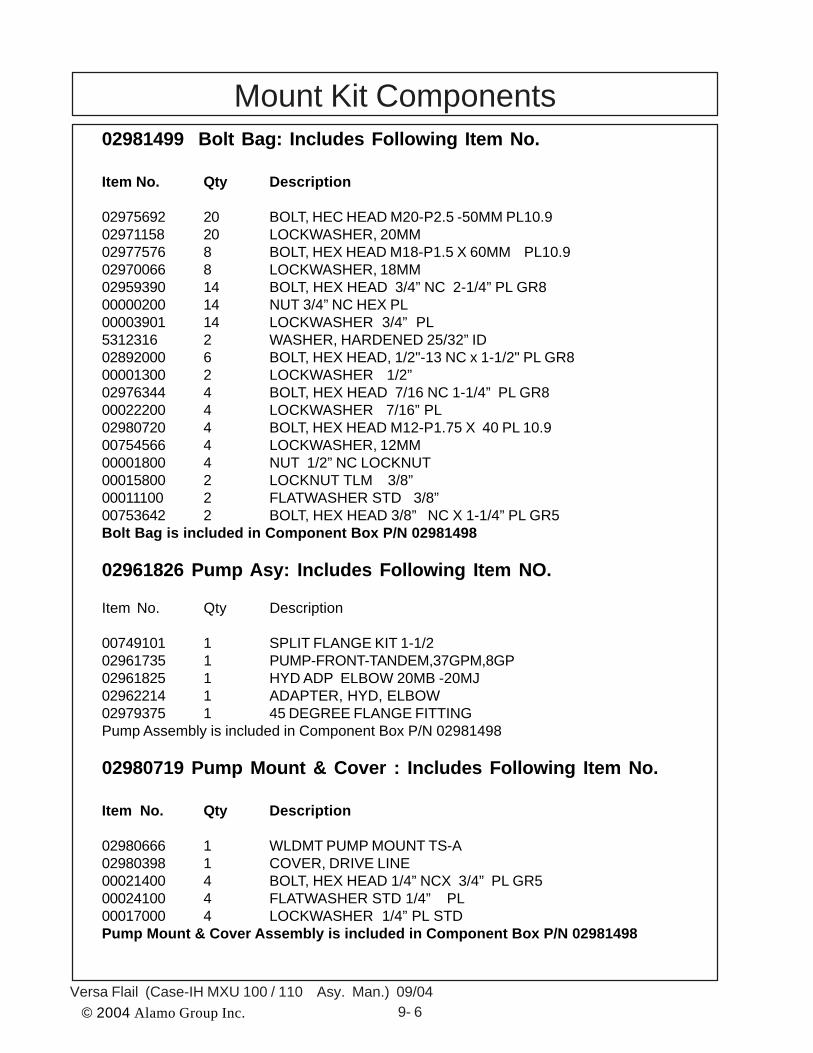
© 2004 Alamo Group Inc. 9- 6Versa Flail (Case-IH MXU 100 / 110 Asy. Man.) 09/04
02981499 Bolt Bag: Includes Following Item No.
Item No. Qty Description
02975692 20 BOLT, HEC HEAD M20-P2.5 -50MM PL10.902971158 20 LOCKWASHER, 20MM02977576 8 BOLT, HEX HEAD M18-P1.5 X 60MM PL10.902970066 8 LOCKWASHER, 18MM02959390 14 BOLT, HEX HEAD 3/4” NC 2-1/4” PL GR800000200 14 NUT 3/4” NC HEX PL00003901 14 LOCKWASHER 3/4” PL5312316 2 WASHER, HARDENED 25/32” ID02892000 6 BOLT, HEX HEAD, 1/2"-13 NC x 1-1/2" PL GR800001300 2 LOCKWASHER 1/2”02976344 4 BOLT, HEX HEAD 7/16 NC 1-1/4” PL GR800022200 4 LOCKWASHER 7/16” PL02980720 4 BOLT, HEX HEAD M12-P1.75 X 40 PL 10.900754566 4 LOCKWASHER, 12MM00001800 4 NUT 1/2” NC LOCKNUT00015800 2 LOCKNUT TLM 3/8”00011100 2 FLATWASHER STD 3/8”00753642 2 BOLT, HEX HEAD 3/8” NC X 1-1/4” PL GR5Bolt Bag is included in Component Box P/N 02981498
02961826 Pump Asy: Includes Following Item NO.
Item No. Qty Description
00749101 1 SPLIT FLANGE KIT 1-1/202961735 1 PUMP-FRONT-TANDEM,37GPM,8GP02961825 1 HYD ADP ELBOW 20MB -20MJ02962214 1 ADAPTER, HYD, ELBOW02979375 1 45 DEGREE FLANGE FITTINGPump Assembly is included in Component Box P/N 02981498
02980719 Pump Mount & Cover : Includes Following Item No.
Item No. Qty Description
02980666 1 WLDMT PUMP MOUNT TS-A02980398 1 COVER, DRIVE LINE00021400 4 BOLT, HEX HEAD 1/4” NCX 3/4” PL GR500024100 4 FLATWASHER STD 1/4” PL00017000 4 LOCKWASHER 1/4” PL STDPump Mount & Cover Assembly is included in Component Box P/N 02981498
Mount Kit Components

© 2004 Alamo Group Inc. 9- 7Versa Flail (Case-IH MXU 100 / 110 Asy. Man.) 09/04
02980717 Exhaust Relocation Kit: Includes Following Item No.
Item No. Qty Description
02980649 1 WLDMT EXHAUST BRACKET02980718 1 WLDMT, TURBO DOWNPIPE02980584 2 KIT 3" EXHAUST CLAMP02980727 4 BOLT, SOCKET HEAD, M8-P1.25 x 35mm PL10.902980728 3 BOLT, HEX HEAD, M12-P1.75 x 30mm PL10.9701513C 3 FLATWASHER M1200754566 3 LOCKWASHER, 12MMExhaust Relocation Kit is included in Component Box P/N 02981498
02980726 Control Stand Kit : Includes Following Item NO.
Item No. Qty Description
00755954 2 LOCKWASHER M10 SPRING00762398 2 BOLT, HEX HEAD, METRIC 10-P1.5 - 30MM PL502980914 1 PLATE, CONTROL STAND NH TS-AControl Stand Kit is included in Component Box P/N 02981498
02981750 Battery Relocation Kit : Includes Following Item NO.
Item No. Qty Description
02981725 1 WLDMT BATTERY BRACKET00011400 3 BOLT, HEX HEAD 3/8” X 1” NC00012101 3 LOCKWASHER 3/8” PL00013901 3 NUT HEX, 3/8” NC PLBattery Relocation Kit is included in Component Box P/N 02981498
DO NOT ORDER ASSEMBLIES UNLESS COMPLETE ASSEMBLYWANTED, IF YOU WANT ASSEMBLY THEN ORDER TOP ASSEMBLYNUMBER ONLY, COMPONENTS IN ASSEMBLIES MAY HAVE MORECOMPONENTS THAN YOU WANT. CHECK BEFORE ORDERING.
Mount Kit Components

© 2004 Alamo Group Inc. 9- 8Versa Flail (Case-IH MXU 100 / 110 Asy. Man.) 09/04
NOTES

© 2004 Alamo Group Inc.
Versa Flail (Case - IH MXU 100 / 110 Asy. Man.) 09/04

© 2004 Alamo Group Inc.
Versa Flail (Case-IH MXU 100 / 110 Asy. Man.) 09/04
Versa Flail Assembly ManualCase-IH MXU 100/110
2004 EditionManual P/N 02981763