Documentation and Metadata for the NESA Weather Station 1986–2008

CITY OF FORT WAYNE MASTER UPDATED: 1/5/15SECTION 01 75 11
CHECKOUT AND STARTUP PROCEDURES
NTS: Include this section on projects when installation and startup of equipment is included under the Contract. This section is intended for use on distribution and collection system projects and does not contain the level of detail often required for treatment facility projects. Edit this section to suit the Project.
PART 1 GENERAL
1.1 DESCRIPTION
A. Scope:1. Contractor shall coordinate initial start-up and place equipment installed under the
Contract into successful operation, in accordance with the equipment manufacturer’s written instructions and as instructed by Supplier at the Site.
2. Provide all material, labor, tools, and equipment required to complete equipment checkout and start-up.
3. Provide chemicals, lubricants, and other operating fluids required for start-up of equipment, unless otherwise specified.
4. Provide fuel, electricity, water, filters, and other expendables required for start-up of equipment, unless otherwise specified.
5. General Activities Include:a. Cleaning, as required under other provisions of the Contract Documents.b. Removing temporary protective coatings.c. Flushing and replacing lubricants, where required by manufacturer.d. Lubrication.e. Checking shaft and coupling alignments and resetting where required.f. Checking and setting motor, pump, and other equipment rotation, safety interlocks,
and belt tensions.g. Checking and correcting (if necessary) leveling plates, grout, bearing plates,
anchorage devices, fasteners, and alignment of piping, conduits, and ducts that may place stress on the connected equipment.
h. All adjustments required.
B. Coordination:1. Coordinate checkout and start-up with Owner, other Contractors and Subcontractors, as
necessary.2. Do not start up system or subsystem for continuous operation until all components of that
system or subsystem, including instrumentation and controls, have been tested to the extent practicable and proven to be operable as intended by the Contract Documents.
3. Owner will provide sufficient personnel to observe during equipment start up, but Contractor shall be responsible for proper operation.
v. 1.15 Checkout and Startup Procedures – 01 75 11-1
4. Supplier shall be present during checkout, start-up, and initial operation, unless otherwise acceptable to Owner or Engineer.
5. Startup of heating and air conditioning equipment and systems is dependent upon the time of the year. Return to the Site at beginning of next heating or air conditioning season (as applicable) to recheck and start the appropriate systems.
6. Do not start up system, unit process, or equipment without submitting acceptable preliminary operations and maintenance manuals, in accordance with Section 01 78 23, Operations and Maintenance Data.
7. Do not start up system, unit process, or equipment until checkout and startup documentation has been submitted and approved by Owner or Engineer.
C. Owner’s Assumption of Operational Responsibility for Equipment and Systems:1. Owner will assume operational responsibility for equipment and systems upon
acceptance of Substantial Completion.2. Prior to turning over system or equipment operation and maintenance responsibility to
Owner, Contractor shall:a. Provide training of operations and maintenance personnel in accordance with
equipment technical specifications. Review equipment sections for applicable material.
b. Complete system field quality control testing in accordance with the Contract Documents.
c. Submit acceptable final operations and maintenance manuals in accordance with Section 01 78 23, Operations and Maintenance Data.
d. Obtain final certificate of Substantial Completion for the entire Work or the portion of Work being turned over to Owner.
e. Transfer all keys and locks for the facility to the Owner.
1.2 RELATED SECTIONS
NTS: Insert at (--1--) below list of sections covering products, construction and equipment that a user might expect to find in this section, but are specified elsewhere. Do not list administrative and procedural Division 01 sections.
A. Section (--1--).
NTS: Section “1.3” is to be included if project is bid on unit price basis. Section to be deleted or revised if project is to be bid on lump sum basis.
1.3 MEASUREMENT AND PAYMENT
A. This item is to be included in overall project cost and not bid as a separate work item.
1.4 DEFINITIONS
A. Checkout: Field inspection, testing, adjustments, and sign off by the approved representative of the manufacturer, indicating that the component, system, or unit process meets the manufacture’s requirements.
v. 1.15 Checkout and Startup Procedures – 01 75 11-2

B. Commissioning: Systematic process of ensuring systems perform interactively according to design intent and Owner’s operational needs. Commissioning process encompasses and coordinates system documentation, equipment startup, instrumentation and control system calibration, testing and balancing, performance testing and training, and verification of actual performance.
C. Person-Day: One person for 8 hours within regular Contractor working hours.
D. Start-up: Placing a component, system or unit process in operation. Start-up can be a commissioning activity or a normal operating activity.
1.5 QUALIFICATION OF MANUFACTURER’S REPRESENTATIVE
A. Authorized representative of the manufacturer, factory trained, and experienced in the technical applications, installation, operation, and maintenance of respective equipment, subsystem, or system, with full authority by the equipment manufacturer to issue the certifications required of the manufacturer. Additional qualifications may be specified in the individual technical specification section(s).
B. Representative subject to acceptance by Owner and Engineer
NTS: Coordinate with individual specification sections where checkout and start-up submittals are specified. Checkout and start-up sections are included when operating equipment is specified.
1.6 SUBMITTALS
NTS: For use by Engineering, Operations, and Maintenance departments; Checkout and Startup documents are required to be submitted prior to Substantial Completion.
Some projects may include multiple “Partial Substantial Completions” tied to portions of the Work accepted by the Owner in stages. For these types of projects, Engineer shall create multiple Submittals of Checkout and Startup submittal items and Contractor shall submit all documents associated with the applicable portion of the Work prior to each request for Substantial Completion.
Coordinate the required submittals below with the requirements of Substantial and Final Completion, as written in Article 4, Contract Times, in the Agreement.
A. Action Submittals: Submit the following:1. Prior to request for certificate of Substantial Completion of the Work or, specified part
thereof, submit the following checkout and startup documents:
NTS: Review and modify items on each checklist. Checklists can be edited to the specific needs of the project or “NA” can be entered in the completion date field to indicate unnecessary items. Verify forms are included in the specifications.
v. 1.15 Checkout and Startup Procedures – 01 75 11-3

a. Commissioning Submittals: Submit the following for each piece of operating equipment. 1) Site/Structural/Mechanical Checklist2) Pump Manufacturer’s Start Up Report3) Lift Station Electrical Inspection Field Documentation4) I&C Point to Point Checklist5) Start-Up Logs6) Test Reports7) Manufactures Certificates
2. Provide an electronic scan of the completed check out and start-up documents in a portable electronic document (PDF), or similar format.
3. Scanned documents shall be clear and legible. 4. Submit in accordance with Section 01 33 00, Submittal Procedures.5. Use templates for certification and checklists provided at the end of this specification
Section, as required.
NTS: If commissioning plan is not required delete section d. See attachments at the end of this section for commissioning plan example.
B. Commissioning Plan
PART 2 PRODUCTS (NOT USED)
PART 3 EXECUTION
3.1 FULFILLMENT OF SPECIFIED SERVICES
A. Furnish manufacturer’s services, when required by an individual technical specification section(s), to meet the requirements of this section.1. Manufacturer’s services shall be provided as required, regardless of any minimum time
specified, until operation of the equipment is satisfactory to Owner, at no additional cost to Owner.
NTS: If commissioning plan is not required delete Section B below.
B. Contractor to prepare the commissioning plan for the project.1. Coordinate meetings for the purposes of completing the commissioning plan.2. Attendance and participation of the following groups at commissioning meetings are
required.a. Engineer’s project representativesb. Owner’s project representativesc. Subcontractorsd. Installerse. Programmersf. Suppliers
v. 1.15 Checkout and Startup Procedures – 01 75 11-4

g. Manufacturer’s representatives as necessary.h. Owner’s maintenance crew personnel.i. Owner’s operations crew personnel.
NTS: Insert at (--2--) the required time information. 3. Submit dates of startup of each item of equipment and system for review (--2--) days
prior to startup.4. Re-submit anticipated startup dates as revised but not less than (--2--) weeks prior to
startup.5. Prefunctional Checklists, functional tests and systems demonstrations are to be performed
in sequence from components, to subsystems, to systems.a. Prefunctional Checklist is required to be filled out for each item of equipment or
other assembly specified to be commissioned.b. No sampling of identical or near identical item is allowed.c. These checklists do not replace manufacturer’s recommended startup checklists,
regardless of apparent redundancy.
C. Schedule manufacturer’s services in coordination with Owner or Engineer to avoid conflict with other onsite testing or other manufacturer’s onsite services.
D. Determine, before scheduling services, that conditions necessary to allow successful testing have been met.
E. Only those days of service approved by Engineer will be credited to fulfill specified minimum services.
F. When not otherwise specified in individual technical specification sections, manufacturer’s onsite services shall include:1. Assistance during product (system, subsystem, or component) installation to include
observation, guidance, instruction of Contractor’s assembly, erection, installation or application procedures.
2. Inspection, checking, and adjustment as required for product (system, subsystem, or component) to function as warranted by manufacturer and necessary Manufacturer’s Certificate of Installation.
3. Providing, on a daily basis, copies of manufacturer’s representatives field notes and data to Engineer.
4. Revisiting the Site as required to correct problems and until installation and operation are acceptable to Engineer.
5. Resolution of assembly or installation problems attributable to or associated with respective manufacturer’s products and systems.
6. Assistance during functional and performance testing, and facility startup and evaluation.
G. Training of Owner’s personnel in the operation and maintenance of respective product as required.
NTS: Edit Article “3.2” and add requirements to suit the project.
v. 1.15 Checkout and Startup Procedures – 01 75 11-5

Edit Paragraph “A” for project requirements and coordinate with specifications that have closeout and start-up requirements listed in individual specifications.
3.2 MINIMUM START-UP REQUIREMENTS
A. General1. Start-up Logs, Test Reports, and Manufacturer’s Certifications are to be filled out during
system and equipment start-up. Information shall be recorded, and submitted on PMIS for approval by engineer.a. Start-up logs shall clearly demonstrate equipment is in conformance with the
Contract Documents and assist maintenance personnel in servicing and adjusting equipment.
b. Test reports shall be in accordance with testing standards and performed by a reliable independent testing laboratory or agency.
c. Manufacturer’s certificate of installation shall be submitted for products ,
B. Bearings and Shafting:1. Inspect for cleanliness, and clean and remove foreign matter.2. Verify alignment.3. Replace defective bearings and those that operate rough or noisy.4. Grease as necessary, in accordance with manufacturer’s recommendations.
C. Motors:1. Check each motor for comparison to amperage nameplate value.2. Correct conditions that produce excessive current flow and conditions that exist due to
equipment malfunction.
D. Pumps:1. Check glands and seals for cleanliness and adjustment before running pump.2. Inspect shaft sleeves for scoring.3. Inspect mechanical faces, chambers, and seal rings, and replace if defective.4. Verify that piping system is free of dirt and scale before circulating liquid through pump.
E. Valves:1. Inspect manual and automatic control valves, and clean bonnets and stems.2. Tighten packing glands to ensure no leakage, but allow valve stems to operate without
galling.3. Replace packing in valves to retain maximum adjustment after system is determined to be
complete.4. Replace packing on valves that continue to leak.5. Remove and repair bonnets that leak.6. After cleaning, coat packing gland threads and valve stems with appropriate surface
preparation.
F. Verify that control valve seats are free of foreign matter and are properly positioned for intended service.
v. 1.15 Checkout and Startup Procedures – 01 75 11-6

G. Tighten flanges and other pipe joints after system has been placed in operation. Replace gaskets that show signs of leakage after tightening.
H. Inspect all joints for leakage:1. Promptly remake each joint that appears to be faulty; do not wait for rust other corrosion
to form.2. Clean threads on both parts, and apply compound and remake joints.
I. After system has been placed in operation, clean strainers, drives, pockets, orifices, valve seats, and headers in fluid system to ensure freedom from foreign matter.
J. Open steam traps and air vents, where used, and remove operating elements. Clean thoroughly, replace internal parts, and place back into operation.
K. Remove rust, scale, and foreign matter from equipment and renew defaced surfaces.
L. Set and calibrate draft gauges of air filters and other equipment.
M. Inspect fan wheels for clearance and balance. Provide factory-authorized personnel for adjustment when needed.
N. Check each electrical control circuit to verify that operation complies with the Contract Documents.
O. Inspect each pressure gauge, thermometer, and other instruments for calibration. Replace items that are defaced, broken, or that read incorrectly.
P. Repair damaged insulation.
Q. Excess Gasses and Fluids:1. Vent gasses trapped in systems.2. Verify that liquids are drained from all parts of gas or air systems.
3.3 ELECTRICAL SYSTEM STARTUP SERVICES
A. Tests and inspections shall establish:1. Electrical equipment is operational within industry and manufacturer’s tolerances and
standards.2. Installation operates properly.3. Equipment is suitable for energizing.
B. Installation conforms to requirements of Contract Documents and NFPA 70, NFPA 70E, NFPA 101, and IEEE C2.
C. Perform inspection and testing in accordance with NETA ATS, industry standards, and manufacturer’s recommendations.
v. 1.15 Checkout and Startup Procedures – 01 75 11-7

D. Set, test and calibrate protective relays, circuit breakers, fuses, power monitoring meters and other applicable devices in accordance with values established by short circuit, coordination, and harmonics studies as specified.
E. Adjust mechanisms and moving parts of equipment for free mechanical movement.
F. Adjust and set electromechanical electronic relays and sensors to correspond to operating conditions, or as recommended by manufacturer.
G. Verify nameplate data for conformance to Contract Documents and approved submittals.
H. Realign equipment not properly aligned and correct discrepancies.
I. Properly anchor electrical equipment found to be inadequately anchored.
J. Tighten accessible bolted connections, including wiring connections, with calibrated torque wrench/screw driver to manufacturer’s recommendations, or as otherwise specified in NETA ATS.
K. Clean contaminated surfaces with cleaning solvents as recommended by manufacturer.
L. Provide proper lubrication of applicable moving parts.
M. Electrical Enclosures:1. Remove foreign material and moisture from enclosure interior.2. Vacuum and wipe clean enclosure interior.3. Remove corrosion found on metal surfaces.4. Repair or replace, as determined by Engineer door and panel sections having dented
surfaces.5. Repair or replace, as determined by Engineer, poor fitting doors and panel sections.6. Repair or replace improperly operating latching, locking, or interlocking devices.7. Replace missing or damaged hardware.8. Finish:
a. Provide matching paint and touch up scratches and mars.b. If required due to extensive damage, as determined by Engineer, refinish entire
assembly.
N. Replace fuses and circuit breakers that do not conform to size and type required by the Contract Documents or approved submittals.
3.4 HVAC SYSTEM STARTUP SERVICES
A. Perform total system balance in accordance with AABC National Standards for Field Measurement and Instrumentation, Total System Balance ASHRAE 111 NEBB Procedural Standards for Testing, Balancing and Adjusting of Environmental Systems.
B. Engage the services of an independent agency specializing in the testing, adjusting, and balancing of systems specified in this Section. The agency shall be acceptable to Owner and Engineer.
v. 1.15 Checkout and Startup Procedures – 01 75 11-8
1. Perform Work under supervision of one of the following:a. AABC Certified Test and Balance Engineer.b. NEBB Certified Testing, Balancing and Adjusting Supervisor.c. Registered Professional Engineer experienced in performance of this Work and
licensed at the place where the Project is located.
C. Perform testing, adjusting and balancing after the equipment is completely installed and ready for continuous operation as required, and when outside conditions approximate design conditions indicated for heating and cooling functions.
D. Examination:1. Verify that systems are complete and operable before commencing Work. Ensure the
following conditions:a. Systems are started and operating in a safe and normal condition.b. Temperature control systems are installed complete and operable.c. Proper thermal overload protection is in place for electrical equipment.d. Final filters are clean and in place. If required, install temporary media in addition
to final filters.e. Duct systems are clean of debris.f. Fans are rotating correctly.g. Fire and volume dampers are in place and open.h. Air coil fins are cleaned and combed.i. Access doors are closed and duct end caps are in place.j. Air outlets are installed and connected.k. Duct system leakage is minimized.l. Hydronic systems are flushed, filled, and vented.m. Pumps are rotating correctly.n. Proper strainer baskets are clean and in place.o. Service and balance valves are open.
2. Submit field reports. Report defects and deficiencies noted during performance of services which prevent system balance.
E. Preparation:1. Provide instruments required for testing, adjusting, and balancing operations. Make
instruments available to Engineer to facilitate spot checks during testing.2. Provide additional balancing devices as required.
F. Installation Tolerances1. Air Handling Systems:
a. Adjust system to within +5 percent of design for supply systems.b. Adjust system to within +10 percent of design for return and exhaust systems.
G. Air Outlets and Inlets:1. Adjust total to space within +10 percent and -5 percent of design to space.2. Adjust individual outlets and inlets in space to within +10 percent of design.
H. Hydronic Systems: Adjust flow to within +10 percent of design.
v. 1.15 Checkout and Startup Procedures – 01 75 11-9

I. Adjusting:1. Ensure recorded data represents actual measured or observed conditions.2. Permanently mark settings of valves, dampers, and other adjustment devices allowing
settings to be restored. Set and lock memory stops.3. After adjustment, take measurements to verify balance has not been disrupted or that such
disruption has been rectified.4. Leave systems in proper working order, replacing belt guards, closing access doors,
closing doors to electrical switch boxes, and restoring thermostats to specified settings.
NTS: Select the following two optional paragraphs as applicable to the project. Avoid 6 month inspection since it could hold up contract completion.
5. At final inspection, recheck random selections of data recorded in report. Recheck points or areas as selected and witnessed by OWNER.
6. Check and adjust systems approximately 6 months after final acceptance and submit report.
J. Air system procedure:1. Identify and list size, type and manufacturer of all equipment to be tested including air
terminals.2. Use manufacturer's ratings for all equipment to make required calculations except where
field test shows ratings to be impractical.3. Adjust air handling and distribution systems to provide required or design supply, return,
and exhaust air quantities at site altitude.4. Make air quantity measurements in ducts by pitot tube traverse of entire cross-sectional
area of duct.5. Test and record motor voltage and running amperes including motor nameplate data, and
starter heater ratings.6. Test and record heating apparatus entering and leaving air temperatures.7. Test and record cooling apparatus entering and leaving air temperatures.8. Measure air quantities at air inlets and outlets.9. Adjust distribution system to obtain uniform space temperatures free from objectionable
drafts and noise.10. Use volume control devices to regulate air quantities only to extent that adjustments do
not create objectionable air motion or sound levels. Effect volume control by duct internal devices such as dampers and splitters.
11. Vary total system air quantities by adjustment of fan speeds. Provide drive changes required. Vary branch air quantities by damper regulation.
12. Provide system schematic with required and actual air quantities recorded at each outlet or inlet.
13. Measure static air pressure conditions on air supply units, including filter and coil pressure drops, and total pressure across the fan. Make allowances for 50 percent loading of filters.
14. Adjust outside air automatic dampers, outside air, return air, and exhaust dampers for design conditions.
15. Where modulating dampers are provided, take measurements and balance at extreme conditions.
v. 1.15 Checkout and Startup Procedures – 01 75 11-10

a. Balance variable volume systems at maximum air flow rate, full cooling, and at minimum air flow rate, full heating.
NTS: Select appropriate phrase below, or delete if not required.16. Measure building static pressure and adjust supply, return, and exhaust air systems to
provide required relationship between each to maintain approximately 0.05 inch positive static pressure near the building entries in clean rooms in ______________________________.
17. Check multi-zone units for motorized damper leakage. Adjust air quantities with mixing dampers set first for cooling, then heating, then modulating.
18. For variable air volume system powered units set volume controller to air flow setting indicated. Confirm connections properly made and confirm proper operation for automatic variable air volume temperature control.
19. On fan-powered VAV boxes, adjust air flow switches for proper operation.20. Check control interlocks and cooperate with CONTRACTOR as required to adjust and
calibrate temperature controls.
K. Water system procedure:1. Adjust water systems to provide required or design quantities.2. Preliminary:
a. List all Mechanical Specifications of tested equipment and verify against Contract Documents.
b. Open all line valves to full open position, close coil bypass stop valves, then set mixing control valve to full coil flow.
c. For each pump; verify rotation, test and record pump shut-off head, and test and record pump wide-open head.
3. Balance flow to each water coil. With glycol systems balance heating and cooling separately at actual operating water temperatures.
4. Terminal Units: Upon completion of flow readings and adjustments at coil, mark all settings and record the following data:a. Inlet water temperature.b. Leaving water temperature.c. Observe and record pressure drop through coil at set flow rate on call for full cooling
and full heating.d. Set valve in bypass to match coil flow pressure drop on full bypass.
5. Pumps: After flow is adjusted to each heating unit, record rated and actual running amperage for each pump motor and total dynamic head for each pump.
6. Adjust heating water systems as necessary to provide the required quantities for each component.
7. Use calibrated Venturi tubes, orifices, or other metered fittings and pressure gages to determine flow rates for system balance. Where flow metering devices are not installed, base flow balance on temperature difference across various heat transfer elements in the system.
8. Adjust systems to provide specified pressure drops and flows through heat transfer elements prior to thermal testing. Perform balancing by measurement of temperature differential in conjunction with air balancing.
9. Effect system balance with automatic control valves fully open to heat transfer elements.
v. 1.15 Checkout and Startup Procedures – 01 75 11-11

10. Effect adjustment of water distribution systems by means of balancing cocks, valves, and fittings. Do not use service or shut-off valves for balancing unless indexed for balance point.
11. Where available pump capacity is less than total flow requirements or individual system parts, full flow in one part may be simulated by temporary restriction of flow to other parts.
L. Control systems:1. In cooperation with the control manufacturer's representative, set and adjust motorized
devices to achieve required sequence of operations.2. Testing organization shall verify controls for proper calibration and list those controls
requiring adjustment.
M. Schedules:
NTS: Provide a schedule to clarify which equipment is to be tested, adjusted, and balanced; to indicate where sound and vibration measurements are required; and to define the report requirements. Keep only equipment that is applicable to the project.
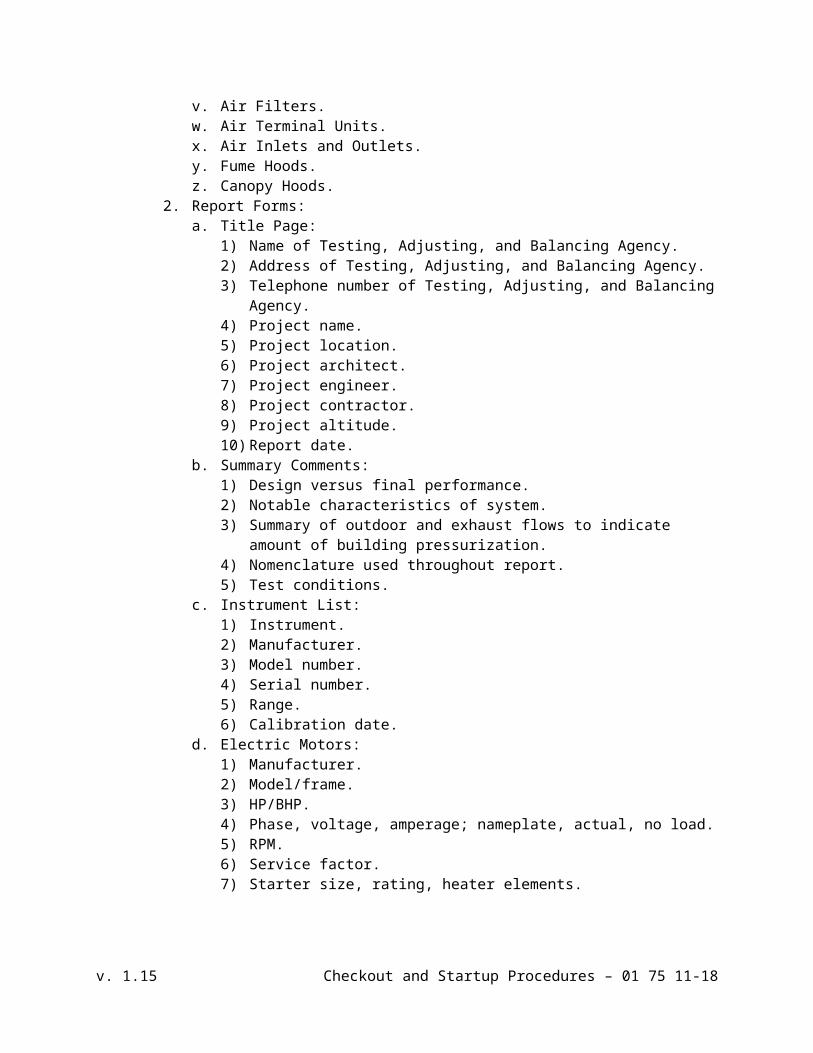
1. Equipment Requiring Testing, Adjusting, and Balancing:a. Plumbing Pumps.b. Steam Condensate Pumps.c. Boiler Feedwater Pumps.d. HVAC Pumps.e. Forced Air Furnacesf. Direct-Fired Furnaces.g. Reciprocating Water Chillers.h. Air-Cooled Water Chillers.i. Centrifugal Water Chillers.j. Air-Cooled Refrigerant Condensers.k. Packaged Roof Top Heating/Cooling Units.l. Packaged Terminal Air Conditioning Units.m. Unit Air Conditioners.n. Computer Room Air Conditioning Units.o. Air Coils.p. Evaporative Humidifier.q. Sprayed Coil Dehumidifier.r. Terminal Heat Transfer Units.s. Induction Units.t. Air Handling Units.u. Fans.v. Air Filters.w. Air Terminal Units.x. Air Inlets and Outlets.y. Fume Hoods.z. Canopy Hoods.
2. Report Forms:a. Title Page:
1) Name of Testing, Adjusting, and Balancing Agency.
v. 1.15 Checkout and Startup Procedures – 01 75 11-12
2) Address of Testing, Adjusting, and Balancing Agency.3) Telephone number of Testing, Adjusting, and Balancing Agency.4) Project name.5) Project location.6) Project architect.7) Project engineer.8) Project contractor.9) Project altitude.10) Report date.
b. Summary Comments:1) Design versus final performance.2) Notable characteristics of system.3) Summary of outdoor and exhaust flows to indicate amount of building
pressurization.4) Nomenclature used throughout report.5) Test conditions.
c. Instrument List:1) Instrument.2) Manufacturer.3) Model number.4) Serial number.5) Range.6) Calibration date.
d. Electric Motors:1) Manufacturer.2) Model/frame.3) HP/BHP.4) Phase, voltage, amperage; nameplate, actual, no load.5) RPM.6) Service factor.7) Starter size, rating, heater elements.8) Sheave make/size/bore.
e. V-Belt Drive:1) Identification/location.2) Required driven rpm.3) Driven sheave, diameter and rpm.4) Belt, size and quantity.5) Motor sheave diameter and rpm.6) Center-to-center distance, maximum, minimum, and actual.
f. Pump Data:1) Identification/number.2) Manufacturer.3) Size/model.4) Impeller.5) Service.6) Design flow rate, pressure drop, BHP.7) Actual flow rate, pressure drop, BHP.8) Discharge pressure.
v. 1.15 Checkout and Startup Procedures – 01 75 11-13

9) Suction pressure.10) Total operating head pressure.11) Shut-off, discharge and suction pressures.12) Shut-off, total head pressure.
g. Air-Cooled Condenser:1) Identification/number.2) Location.3) Manufacturer.4) Model number.5) Serial number.6) Entering DB air temperature, design and actual.7) Leaving DB air temperature, design and actual.8) Number of compressors.
h. Chillers:1) Identification/number.2) Manufacturer.3) Capacity.4) Model number.5) Serial number.6) Evaporator entering water temperature, design and actual.7) Evaporator leaving water temperature, design and actual.8) Evaporator pressure drop, design and actual.9) Evaporator water flow rate, design and actual.10) Condenser entering water temperature, design and actual.11) Condenser pressure drop, design and actual.12) Condenser water flow rate, design and actual.
i. Cooling Tower:1) Tower identification/number.2) Manufacturer.3) Model number.4) Serial number.5) Rated capacity.6) Entering air WB temperature, specified and actual.7) Leaving air WB temperature, specified and actual.8) Ambient air DB temperature.9) Condenser water entering temperature.10) Condenser water leaving temperature.11) Condenser water flow rate.12) Fan rpm.
j. Heat Exchanger:1) Identification/number.2) Location.3) Service.4) Manufacturer.5) Model number.6) Serial number.7) Steam pressure, design and actual.8) Primary water entering temperature, design and actual.
v. 1.15 Checkout and Startup Procedures – 01 75 11-14

9) Primary water leaving temperature, design and actual.10) Primary water flow, design and actual.11) Primary water pressure drop, design and actual.12) Secondary water leaving temperature, design and actual.13) Secondary water leaving temperature, design and actual.14) Secondary water flow, design and actual.15) Secondary water pressure drop, design and actual.
k. Cooling Coil Data:1) Identification/number.2) Location.3) Service.4) Manufacturer.5) Air flow, design and actual.6) Entering air DB temperature, design and actual.7) Entering air WB temperature, design and actual.8) Leaving air DB temperature, design and actual.9) Leaving air WB temperature, design and actual.10) Water flow, design and actual.11) Water pressure drop, design and actual.12) Entering water temperature, design and actual.13) Leaving water temperature, design and actual.14) Saturated suction temperature, design and actual.15) Air pressure drop, design and actual.
l. Heating Coil Data:1) Identification/number.2) Location.3) Service.4) Manufacturer.5) Air flow, design and actual.6) Water flow, design and actual.7) Water pressure drop, design and actual.8) Entering water temperature, design and actual.9) Leaving water temperature, design and actual.10) Entering air temperature, design and actual.11) Leaving air temperature, design and actual.12) Air pressure drop, design and actual.
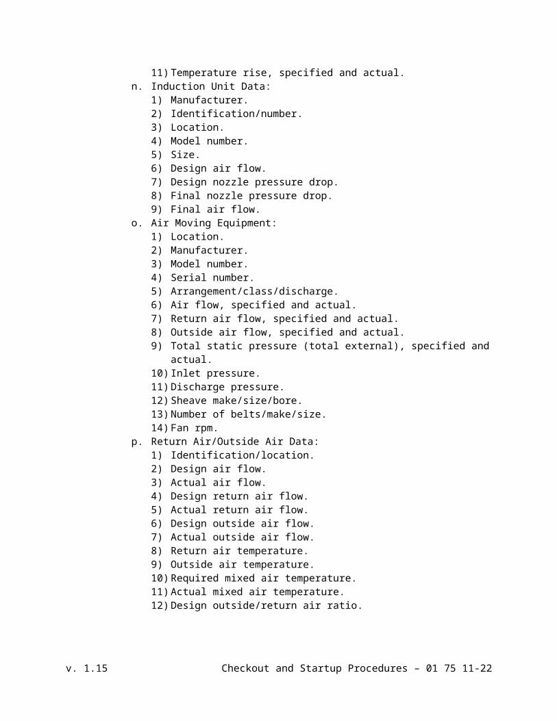
m. Electric Duct Heater:1) Manufacturer.2) Identification/number.3) Location.4) Model number.5) Design kW.6) Number of stages.7) Phase, voltage, amperage.8) Test voltage (each phase).9) Test amperage (each phase).10) Air flow, specified and actual.11) Temperature rise, specified and actual.
v. 1.15 Checkout and Startup Procedures – 01 75 11-15

n. Induction Unit Data:1) Manufacturer.2) Identification/number.3) Location.4) Model number.5) Size.6) Design air flow.7) Design nozzle pressure drop.8) Final nozzle pressure drop.9) Final air flow.
o. Air Moving Equipment:1) Location.2) Manufacturer.3) Model number.4) Serial number.5) Arrangement/class/discharge.6) Air flow, specified and actual.7) Return air flow, specified and actual.8) Outside air flow, specified and actual.9) Total static pressure (total external), specified and actual.10) Inlet pressure.11) Discharge pressure.12) Sheave make/size/bore.13) Number of belts/make/size.14) Fan rpm.
p. Return Air/Outside Air Data:1) Identification/location.2) Design air flow.3) Actual air flow.4) Design return air flow.5) Actual return air flow.6) Design outside air flow.7) Actual outside air flow.8) Return air temperature.9) Outside air temperature.10) Required mixed air temperature.11) Actual mixed air temperature.12) Design outside/return air ratio.13) Actual outside/return air ratio.
q. Exhaust Fan Data:1) Location.2) Manufacturer.3) Model number.4) Serial number.5) Air flow, specified and actual.6) Total static pressure (total external), specified and actual.7) Inlet pressure.8) Discharge pressure.
v. 1.15 Checkout and Startup Procedures – 01 75 11-16
9) Sheave make/size/bore.10) Number of belts/make/size.11) Fan rpm.
r. Duct Traverse:1) System zone/branch.2) Duct size.3) Area.4) Design velocity.5) Design air flow.6) Test velocity.7) Test air flow.8) Duct static pressure.9) Air temperature.10) Air correction factor.
s. Air Monitoring Station Data:1) Identification/location.2) System.3) Size.4) Area.5) Design velocity.6) Design air flow.7) Test velocity.8) Test air flow.
t. Flow Measuring Station:1) Identification/number.2) Location.3) Size.4) Manufacturer.5) Model number.6) Serial number.7) Design flow rate.8) Design pressure drop.9) Actual/final pressure drop.10) Actual/final flow rate.11) Station-calibrated setting.
u. Terminal Unit Data:1) Manufacturer.2) Type, constant, variable, single, dual duct.3) Identification/number.4) Location.5) Model number.6) Size.7) Minimum static pressure.8) Minimum design air flow.9) Maximum design air flow.10) Maximum actual air flow.11) Inlet static pressure.
v. Air Distribution Test Sheet:
v. 1.15 Checkout and Startup Procedures – 01 75 11-17
1) Air terminal number.2) Room number/location.3) Terminal type.4) Terminal size.5) Area factor.6) Design velocity.7) Design air flow.8) Test (final) velocity.9) Test (final) air flow.10) Percent of design air flow.
w. Sound Level Report:1) Location.2) Octave bands - equipment off.3) Octave bands - equipment on.
x. Vibration Test:1) Location of Points:
a) Fan bearing, drive end.b) Fan bearing, opposite end.c) Motor bearing, center (if applicable).d) Motor bearing, drive end.e) Motor bearing, opposite end.f) Casing (bottom or top).g) Casing (side).h) Duct after flexible connection (discharge).i) Duct after flexible connection (suction).
2) Test Readings:a) Horizontal, velocity and displacement.b) Vertical, velocity and displacement.c) Axial, velocity and displacement.
3) Normally acceptable readings, velocity and acceleration.4) Unusual conditions at time of test.5) Vibration source (if non-complying).
NTS: Insert at (--1--) one of the following: “life safety”, “smoke excavation”, or “smoke control”, or delete if not required.
N. Schedule and provide assistance in final adjustment and test of (--1--) system with Fire Authority.
NTS: Delete Section 3.5 if input/output and software testing are not included in contract.
3.5 FIELD INPUT/OUTPUT AND SOFTWARE TESTING
A. General:1. Field testing is intended to check installation of the Process Control System PLC in
addition to providing a diagnostic check of field equipment and wiring.
v. 1.15 Checkout and Startup Procedures – 01 75 11-18

NTS: Delete No. 2 if operator workstation is not included in the contract. 2. Field testing shall make use of operator workstation provided. Install PLC programming
software onto operator workstation, and provide any configuration required to establish Ethernet communications with the Process Control System PLC.
3. Testing shall begin after Process Control System PLC has been installed and all terminations are complete.
4. Use PLC configuration utilized for In-Factory Testing.5. Test as follows:
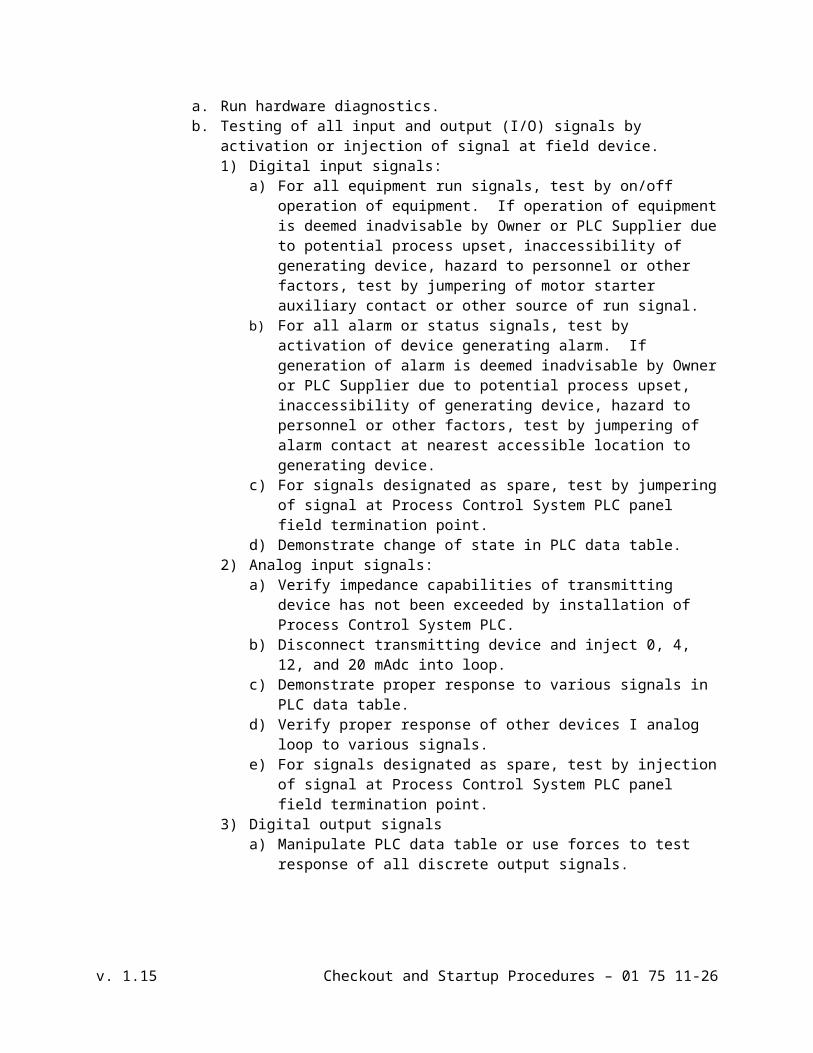
a. Run hardware diagnostics.b. Testing of all input and output (I/O) signals by activation or injection of signal at
field device.1) Digital input signals:
a) For all equipment run signals, test by on/off operation of equipment. If operation of equipment is deemed inadvisable by Owner or PLC Supplier due to potential process upset, inaccessibility of generating device, hazard to personnel or other factors, test by jumpering of motor starter auxiliary contact or other source of run signal.
b) For all alarm or status signals, test by activation of device generating alarm. If generation of alarm is deemed inadvisable by Owner or PLC Supplier due to potential process upset, inaccessibility of generating device, hazard to personnel or other factors, test by jumpering of alarm contact at nearest accessible location to generating device.
c) For signals designated as spare, test by jumpering of signal at Process Control System PLC panel field termination point.
d) Demonstrate change of state in PLC data table.2) Analog input signals:
a) Verify impedance capabilities of transmitting device has not been exceeded by installation of Process Control System PLC.
b) Disconnect transmitting device and inject 0, 4, 12, and 20 mAdc into loop.c) Demonstrate proper response to various signals in PLC data table.d) Verify proper response of other devices I analog loop to various signals.e) For signals designated as spare, test by injection of signal at Process
Control System PLC panel field termination point.3) Digital output signals
a) Manipulate PLC data table or use forces to test response of all discrete output signals.
b) Verify proper response of other devices in loop to signals.c) For signals designated as spare, test by checking signal at Process Control
System PLC panel field termination point.4) Analog Output Signals
a) Verify impedance capabilities of analog output is not exceeded.b) Generate 4, 12, and 20 mAdc signals for all analog outputs through PLC
data table.c) Verify proper response of other devices in analog loop to various signals.
Verify proper loop current through measurement.d) For signals designated as spare, test by measuring of signal at Process
Control System PLC panel field termination point.
v. 1.15 Checkout and Startup Procedures – 01 75 11-19

6. Documentationa. Prepare field testing sign-off document. Document shall include following as a
minimum:1) Project description and number.2) Company name for PLC Supplier, Owner, and Engineer.3) For each I/O point, include area for initials of PLC Supplier’s, Owner’s,
and Engineer’s representative indicating passing of inspection. Include separate line for I/O point to be tested.
4) Include area for handwritten notes of any corrections required.7. Problem Field Devices or Wiring
a. Provide written documentation of any problems encountered with Owner’s field devices or wiring during testing. Correction of such problems is not considered part of this project.
3.6 ATTACHMENTS
A. Site/Structural/Mechanical Checklist
B. Pump Manufacturer’s Start Up Report
C. Lift Station Electrical Inspection Field Documentation
D. I&C Point to Point Checklist
E. Commissioning Plan Template
+ + END OF SECTION + +
v. 1.15 Checkout and Startup Procedures – 01 75 11-20

CERTIFICATE OF INSTALLATION SERVICES
Project
Equipment
Specification Section
Contract
I hereby certify the equipment supplier/manufacturer has inspected this equipment and that it has been properly installed, functionally tested, adjusted, and calibrated. I further certify this equipment may now be operated for test purposes and/or normal use.
MANUFACTURER’S REPRESENTATIVE
Signature Date
Name (print)
Title
Representing
CONTRACTOR
Signature Date
Name (print)
Title
Comments:
This form shall be completed and submitted to ENGINEER prior to training of Owner’s personnel in accordance with Section 01 79 23.
v. 1.15 Checkout and Startup Procedures – 01 75 11-21
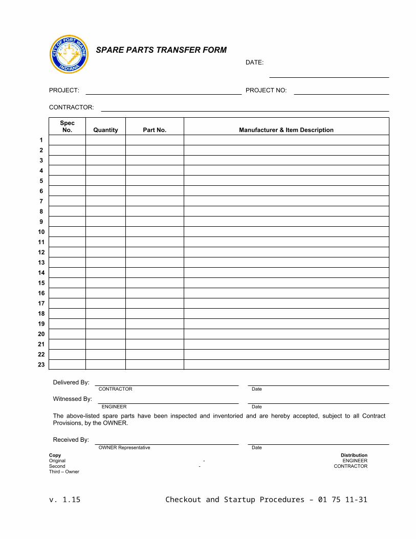
SPARE PARTS TRANSFER FORMDATE:
PROJECT: PROJECT NO:
CONTRACTOR:
SpecNo. Quantity Part No. Manufacturer & Item Description
123456789
1011121314151617181920212223
Delivered By:CONTRACTOR Date
Witnessed By:ENGINEER Date
The above-listed spare parts have been inspected and inventoried and are hereby accepted, subject to all Contract Provisions, by the OWNER.
Received By:OWNER Representative Date
Copy DistributionOriginal - ENGINEERSecond - CONTRACTORThird – Owner
v. 1.15 Checkout and Startup Procedures – 01 75 11-22

Project Name:
_________________________
Project No.:______________
Contractor Name:
_________________________
Date:____________________
SITE, STRUCTURAL, &MECHANICAL FACILITY CHECK LIST
Completion Date
SITE
Fence, gate, lock as specified
Paving as specified, no birdbaths
Storm drain grates clean and open
Site graded to prevent ponding and flooding
All grass areas growing and as specified; ____ inches of topsoil as required
All shrubbery alive and as specified
Fire hydrant as specified and operating, if applicable
Stone provided over vinyl cloth wee barrier as specified
BUILDING
Automatic transfer switch operable and as specified
County electrical inspection certificate received
Check all lights including photo electric cells
Check all receptacles
HATCHES
As specified in submittal review
Bituminous coating on frame areas in contact with concrete
Automatic hold open devices working
Slam latch with removable key, spare keys furnished
Flush handle
v. 1.15 Checkout and Startup Procedures – 01 75 11-23

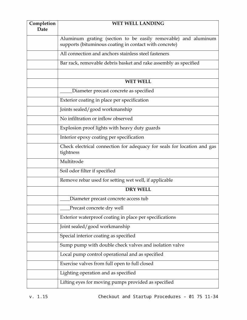
Completion Date
WET WELL LANDING
Aluminum grating (section to be easily removable) and aluminum supports (bituminous coating in contact with concrete)
All connection and anchors stainless steel fasteners
Bar rack, removable debris basket and rake assembly as specified
WET WELL
_____Diameter precast concrete as specified
Exterior coating in place per specification
Joints sealed/good workmanship
No infiltration or inflow observed
Explosion proof lights with heavy duty guards
Interior epoxy coating per specification
Check electrical connection for adequacy for seals for location and gas tightness
Multitrode
Soil odor filter if specified
Remove rebar used for setting wet well, if applicable
DRY WELL
____Diameter precast concrete access tub
____Precast concrete dry well
Exterior waterproof coating in place per specifications
Joint sealed/good workmanship
Special interior coating as specified
Sump pump with double check valves and isolation valve
Local pump control operational and as specified
Exercise valves from full open to full closed
Lighting operation and as specified
Lifting eyes for moving pumps provided as specified
v. 1.15 Checkout and Startup Procedures – 01 75 11-24

Completion Date
VALVE VAULT
Pump around connections and valving as specified
Couplings with dust plugs on brass chain in place
Sump pits with floor sloped to drain (test with water)
Exercise all valves from full open to full closed (control flow to prevent spills)
Valve operator extensions in roadway boxes within one foot of grade and aligned with boxes
PUMP
Pump service record card completed
Manufacturer’s certifications at site
Factory certification that pumps will perform satisfactorily at each design condition
Pressure gauges as specified
Packing and/or mechanical seals as specified
Pump tags provided
PUMP MOTORS
_____Phase, _____Cycle, _____Volts
_____Efficiency, _____Power factor at full load
Vertical squirrel cage, cast iron body
Class _____ insulation
_____Service factor
Starters balance with capacitors to give _____power factor
Certification of factory test
Check amp draw: Pump #1_____ Pump #2_____
Check operating conditions (meet design conditions)
Completion SUBMERSIBLE PUMPS
v. 1.15 Checkout and Startup Procedures – 01 75 11-25
Date
Pull and reset each pump
Check guide rails and pump connection seats
Check electrical connections for adequacy and seals for gas tightness
Check amp draw: Pump #1_____ Pump #2_____
PACKAGE PUMP STATION
Certifications
Installation plumb
Preservation
Base meets specifications
SPARE PARTS
Number required – attach required form and have appropriate signatures
Condition/preservation
Released to Owner
OPERATOR TRAINING
Tour and familiarization
Pumps and motors
Odor control system
Motor control centers
PIPING
Remove temporary pipe plugs
Return City provided water meter if applicable
v. 1.15 Checkout and Startup Procedures – 01 75 11-26

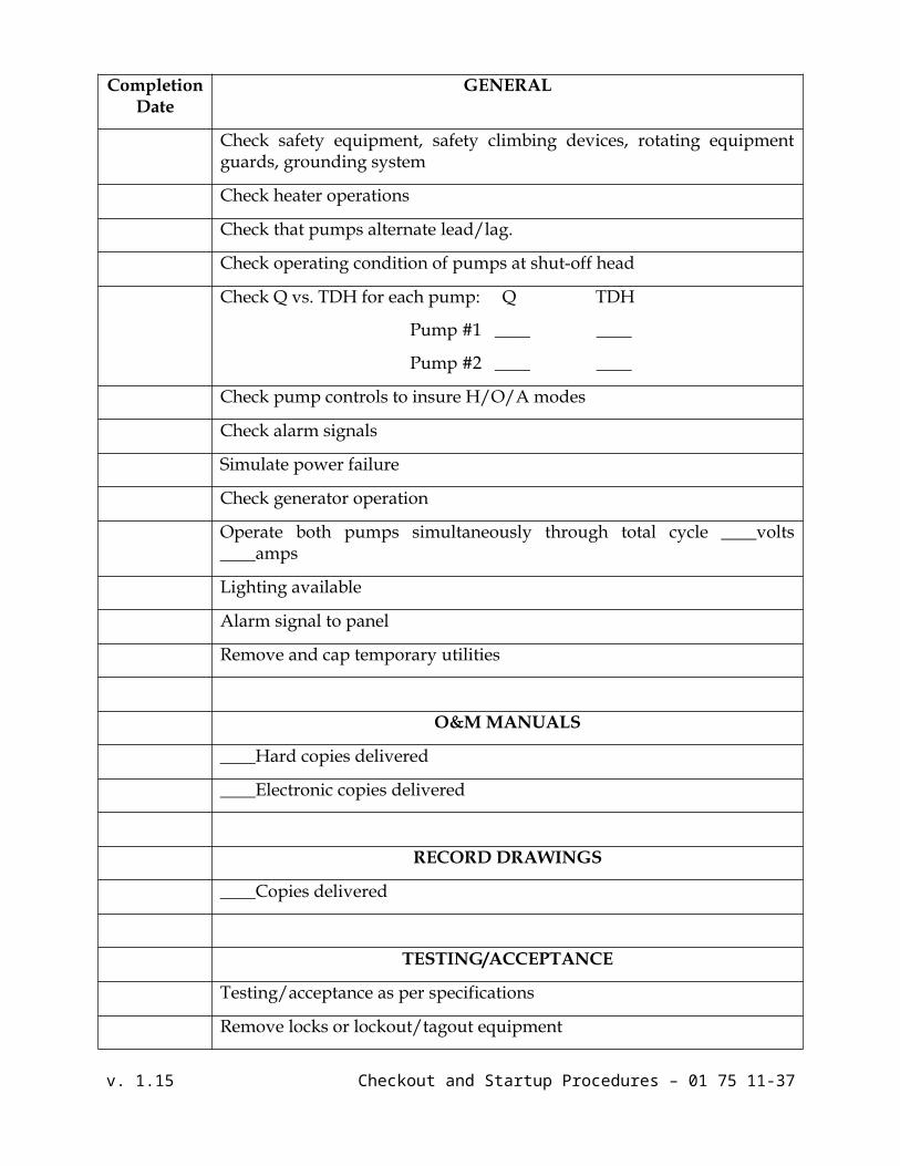
Completion Date
GENERAL
Check safety equipment, safety climbing devices, rotating equipment guards, grounding system
Check heater operations
Check that pumps alternate lead/lag.
Check operating condition of pumps at shut-off head
Check Q vs. TDH for each pump: Q TDH
Pump #1 ____ ____
Pump #2 ____ ____
Check pump controls to insure H/O/A modes
Check alarm signals
Simulate power failure
Check generator operation
Operate both pumps simultaneously through total cycle ____volts ____amps
Lighting available
Alarm signal to panel
Remove and cap temporary utilities
O&M MANUALS
____Hard copies delivered
____Electronic copies delivered
RECORD DRAWINGS
____Copies delivered
TESTING/ACCEPTANCE
Testing/acceptance as per specifications
Remove locks or lockout/tagout equipment
v. 1.15 Checkout and Startup Procedures – 01 75 11-27

PUMP MANUFACTURER’S START UP REPORT
Project Name: Project No.:
Pump Station I.D.: Date:
Pump No. 1 Serial No.: Impellor:
Pump No. 2 Serial No.: Impellor:
Horse Power: RPM:
Voltage/Cycles/Phases: Volts Cycles Phase
PUMP NO. 1 PUMP NO. 2MEG Ohm CheckRed – Black: Ohms Ohms
Red – White: Ohms Ohms
White – Black: Ohms Ohms
Moisture Sensor: Ohms Ohms
Voltage, Pump “Off”L1 – L2: V V
L2 – L3: V V
L3 – L1: V V
Voltage, Pump “On”L1 – L2: V V
L2 – L3: V V
L3 – L1: V V
AmperageL1 Amps Amps
L2 Amps Amps
L3 Amps Amps
Flow gpm gpm
TDH FT FT
Shut-off Head FT FT
**Attach pump curve with design and operating conditions showing pump manufacturer: Pump Manufacturer:Authorized Manufacturer’sRepresentative’s Signature: Date:
v. 1.15 Checkout and Startup Procedures – 01 75 11-28

I. Lift Station General Information:
Lift Station: _______________________________ Date (Site Visit): ___________________
Location/Address: ________________________________ Inspected by (CUE Representative):_________________
Inspected by (WPCP Representative):_________________
A. Pump General Information:
Number of Pumps: __________ Type: ____________________
Horse Power (HP): __________ Pump Manufacture: ___________ Model #: __________
Date of Installation: _________________________
B. Electrical General Information:
Voltage: _____ V Current: _____ A Phase: _____φ (if 1φ fill out VFD info, otherwise disregard).
Back-up Power: No (or) Yes (dual feed, standby generator, and receptacle)
1) Station Load (Calculated & Actual)
Station Max KW (Calculated): _____ KW Station 80% Loaded KW (Calculated): _____ KW
2) Actual LS Current Reading: _____ A (Station FLA)
Station Max KW (Actual): _____ KW Station 80% Loaded KW (Actual): _____ KW
3) Control Panel FLA: _____ A (As indicated on documentation-drawings at station)
Station Max KW (Designed): _____ KW Station 80% Loaded KW (Designed): _____ KW
C. Electrical Utility General Information:
1) Electric Utility Provider: ___________________
2) Meter Number: _______________ Account Number: ____________
3) Service: Overhead (or) Underground
4) Pole Number: __________ (Provide pole numbers if applicable.)
5) Account Rep Contact Information
a. Name: ________________________
b. Phone Number: (office) _____________ (cell) _____________
c. Email Address: __________________________________________
v. 1.15 Checkout and Startup Procedures – 01 75 11-29
(Based on Voltage at station and Discount (MTS) size)

Field Documentation (cont’d.) Lift Station: _______________________________ Date (Site Visit): ___________
Location/Address: ________________________________
II. Lift Station Electrical Equipment:
A. (MTS) or Disconnect Information:
1. Manufacture: ________________________________
(Use Table 1 Guide Below to Indentify Safety Switch Type – Characteristics)
Table 1: Product Selection Guide
B. Pump Control Panel:
1. General Information
i. Panel Manufacture: _______________________
ii. Project Number: __________________________
iii. Drawing Number: _________________________
iv. Line Voltage: _____ V Coil Voltage: _____ A Phase: _____φ 60 Hz
v. Panel HP: _________ Panel FLP: ____________
v. 1.15 Checkout and Startup Procedures – 01 75 11-30
Field Documentation (cont’d.) Lift Station: _______________________________ Date (Site Visit): ___________
Location/Address: ________________________________
2. Documentation
i. Laminated Electrical Drawings inside cabinet: Yes (or) No
1. Updated (notes): __________________________________
3. Circuit Breaker
Table 2Circuit Breaker Information
Amp Serves Manufacture Voltage
4. Equipment
i. Pump Controller
1. Controller: MultiSmart MultiTrode Other
a. Manufacture: ____________________
b. Serial #: __ __ __ __ __ __ __
c. Build Version #: __ . __ . __
d. Serial #: ____________________
e. SITE CODE # __ __: __ __: __ __: __ __: __ __:__ __
f. SITE KEY: (32 digits) __ __ __ __ __ __ __ __ __ __ __ __ __ __ __ __ __ __ __ __ __ __
__ __ __ __ __ __ __ __ __ __
2. Features:
a. Motor Protection ___ DNP3 ___ Modbus ___ Flow ___ PumpView ___ VFD ___ RTU ___
b. Other Features: ___________________________________
v. 1.15 Checkout and Startup Procedures – 01 75 11-31

Field Documentation (cont’d.) Lift Station: _______________________________ Date (Site Visit): ___________
Location/Address: ________________________________
ii. Motor Starter
Table 3Motor Starter Information
Pump # Manufacture Size Pole Cat. Style (AC/DC) Model
1
2
3
4
iii. Controller Transformer
1. ______kVA; _______Hz; _______UL
2. Manufacture: _____________________________
iv. Flygt Mini-CAS
1. Part #: _______________
v. Battery Charger
2. ________V
3. Manufacture: _____________________________
III. Telemetry
A. General Information:
1. ___Yes ___No
2. Radio Type: ___________ Model #: ________________
i. MultiSmart RTU: ___Yes ___No
ii. Zetron: ___Yes ___No
a. Part #: ____________________
b. Model #: ____________________
c. Serial #: ____________________
B. Radio Configuration Route Numbers and Tower Locations (repeater site)
i. Tower (Repeater Site): _______________
ii. Route Number: ______________
v. 1.15 Checkout and Startup Procedures – 01 75 11-32

Field Documentation (cont’d.) Lift Station: _______________________________ Date (Site Visit): ___________
Location/Address: ________________________________
IV. Other Electrical Station Equipment (Specialized):
A. VFD (Variable Frequency Drive): ___Yes ___No {Purpose: Phase Conversion Only}
1. General Information:
i. Manufacture: ____________________
ii. Part #: ____________________
iii. Serial #: ____________________
iv. Model #: ____________________
v. Purpose: Phase Conversion Only
(Use Table 4 Guide Below to Indentify VFD Type – Characteristics)
Table 4: VFD Product Selection Guide
v. 1.15 Checkout and Startup Procedures – 01 75 11-33
Field Documentation (cont’d.) Lift Station: _______________________________ Date (Site Visit): ___________
Location/Address: ________________________________
B. Cooling Unit ___Yes ___No {Enclosures where pump control and VFD combined}
1. Manufacture: ________________________________
(Use Table 5 Guide Below to Indentify Cooling Unit Type – Characteristics)
Table 5IceQube Information
Product # BTU/HR Volts/Hz Max Amps Max Temp Weight Dimensions
1
C. Soft Start: ___Yes ___No {Purpose: Phase Conversion Only}
1. Manufacture: ____________________
2. Part #: ____________________
3. Serial #: ____________________
4. Model #: ____________________
V. Back-up Power
A. Dual Feed – Electric Utility Substation Information
1) Fed from: Sub Station #1: ______________ Sub Station #2: ______________
B. Standby Generator
1) Manufacture: _______________ Generator Size: _____ KW
i. Fuel Type: Natural Gas or Diesel Service Provider (Company): __________
ii. Meter #: _____________ Account # ____________
2) Automatic Transfer Switch
i. Manufacture: ________________________________
ii. Part Number: ________________________________
C. Receptacle
1) General
i. Manufacture: Crouse-Hinds Appleton (Powertite Series) Hubbell
Other: ________________________
ii. Part Number: ________________
iii. Cap Type: Spring Cape (or) Wing Nut Condition: ___________________________
2) Portable Generator Information
i. Primary Portable Generator: 50kW 150kW 300kW
Jumper Cables Required: Yes No
(If Yes, use Table 6-8 to Indentify Jumper Cable Required to Service LS)
v. 1.15 Checkout and Startup Procedures – 01 75 11-34

Field Documentation (cont’d.) Lift Station: _______________________________ Date (Site Visit): ___________
Location/Address: ________________________________
Table 650kW Generator
Voltage Amperage Generator End
Matting Connector Description Receptacle
End
240 200 200 Amp Male
APR20428-S22 Connected to 100 Amp
Female
480 100 100 Amp Male No Jumper Cables Needed
Table 7150kW Generator
Table 8300kW Generator
i. Secondary Portable Generator: 50kW 150kW 300kW
Jumper Cables Required: Yes No
(If Yes, use Table 9-11 to Indentify Jumper Cable Required to Service LS)
Table 950kW Generator
v. 1.15 Checkout and Startup Procedures – 01 75 11-35
Voltage Amperage Generator End
Matting Connector Description Receptacle
EndMatting
Plug
240 400 400 Amp Male
APR40428-S22 Connected to 200 Amp
FemaleAP20468-
S22
240 400 400 Amp Male
APR40428-S22 Connected to 100 Amp
FemaleAPJ10487-
S22
480 200 200 Amp Male
APR20428-S22 Connected to 100 Amp
FemaleAPJ10487-
S22
Voltage Amperage Generator End
Matting Connector Description Receptacle
EndMatting
Plug
240 200 200 Amp Male
APR20428-S22 Connected to 100 Amp
FemaleAPJ10487-
S22
480 400 400 Amp Male
APR40428-S22 Connected to 200 Amp
FemaleAP20468-
S22
480 400 400 Amp Male
APR40428-S22 Connected to 100 Amp
FemaleAPJ10487-
S22
Voltage Amperage Generator End
Matting Connector Description Receptacle
End
240 200 200 Amp Male
APR20428-S22 Connected to 100 Amp
Female
480 100 100 Amp Male No Jumper Cables Needed

Field Documentation (cont’d.) Lift Station: _______________________________ Date (Site Visit): ___________
Location/Address: ________________________________
Table 10150kW Generator
Table 11300kW
Generator
Miscellaneous Note: ____________________________________________________________________
_____________________________________________________________________________________
_____________________________________________________________________________________
_____________________________________________________________________________________
_____________________________________________________________________________________
_____________________________________________________________________________________
v. 1.15 Checkout and Startup Procedures – 01 75 11-36
Voltage Amperage Generator End
Matting Connector Description Receptacle
EndMatting
Plug
240 400 400 Amp Male
APR40428-S22 Connected to 200 Amp
FemaleAP20468-
S22
240 400 400 Amp Male
APR40428-S22 Connected to 100 Amp
FemaleAPJ10487-
S22
480 200 200 Amp Male
APR20428-S22 Connected to 100 Amp
FemaleAPJ10487-
S22
Voltage Amperage Generator End
Matting Connector Description Receptacle
EndMatting
Plug
240 200 200 Amp Male
APR20428-S22 Connected to 100 Amp
FemaleAPJ10487-
S22
480 400 400 Amp Male
APR40428-S22 Connected to 200 Amp
FemaleAP20468-
S22
480 400 400 Amp Male
APR40428-S22 Connected to 100 Amp
FemaleAPJ10487-
S22
Field Documentation (cont’d.) Lift Station: _______________________________ Date (Site Visit): ___________
Location/Address: ________________________________
Station Electrical Riser Diagram
v. 1.15 Checkout and Startup Procedures – 01 75 11-37

I & C Point to Point ChecklistProject Name: Project No.: I&C Contractor Contact Information
Name:_______________________________________________________Company: ___________________________________________________Address: ____________________________________________________Phone: ______________________________________________________PLC Supplier:__________________________________________
I/O AddressLocation
(Drop/Slot/Point)Tag
Type I/O DescriptionOwner Initials
Designer Initials
Engineer’sInitials
Date Completed Comments
Example: 0430-PLC-1
Drop 2, Slot 9, Point 1 RO Ferric Chloride Pump Air Valve #5
ZS BB BE 4/29/2011 Normally Closed
v. 3.14 Startup and Checkout Procedures – 01 75 11-38

Project Commissioning Plan**To be developed at a later time.
v. 3.14 Startup and Checkout Procedures – 01 75 11-39