
009Lighting
52
293 Chapter 9 LightingChapter9: In this chapter you will learn about lighting. Proper lighting is an important element in developing a convincing and realistic CG image. In the lessons that follow, you will learn how light works in the real world and how to simulate real world behavior digitally. Objectives After completing this chapter, you will be able to: ■ Create and manipulate lights ■ Create a simple 3 point lighting setup ■ Use lighting tools ■ Apply how light works in the real world appears to your CG Scenes ■ Simulate the sun in a CG scene
-
Upload
barry-smith -
Category
Documents
-
view
213 -
download
0
description
In this chapter you will learn about lighting. Proper lighting is an important element in developing a convincing and realistic CG image. In the lessons that follow, you will learn how light works in the real world and how to simulate real world behavior digitally. Apply how light works in the real world appears to your CG Scenes Create and manipulate lights Simulate the sun in a CG scene Create a simple 3 point lighting setup After completing this chapter, you will be able to: I I I I I
Transcript of 009Lighting

293
Chapter
9
LightingChapter 9:
In this chapter you will learn about lighting. Proper lighting is an important element in
developing a convincing and realistic CG image. In the lessons that follow, you will learn
how light works in the real world and how to simulate real world behavior digitally.
Objectives
After completing this chapter, you will be able to:
n Create and manipulate lights
n Create a simple 3 point lighting setup
n Use lighting tools
n Apply how light works in the real world appears to your CG Scenes
n Simulate the sun in a CG scene

294 n Chapter 9: Lighting
Lesson: Lights
Overview
Lighting is an essential part of the visual process. Without proper lighting, the best models, materials
and camera placements will not create good images. 3ds Max® and 3ds Max Design offer a variety of
ways to achieve proper lighting. In this lesson, you will learn about various light types and some
fundamentals of lighting.
Objectives
After completing this lesson, you will be able to:
n Use the Standard Light types
n Describe how Photometric Lights work
n Use Mental Ray Area Lights
n Use Color, Intensity and Distribution of lights to create lighting setups
n Apply and modify different shadow types to lights in a scene

Lesson: Lights n 295
Standard Lights
Standard lights are very flexible and easy to use. They can be controlled and adapted to fit the kind of
lighting designed by the artist. They are not physically accurate but their range of controls helps
achieving the kind of realism an artist craves for.
Omni Light
Spotlight
The Omni light simulates rays shining out from
a single point in space. Rays are emitted
uniformly in all directions. This is somewhat
similar to a bare light bulb.
The Spot light also simulates rays shining out
from a single point but limits the illumination
to a specific cone-shaped volume. This kind of
control, which allows you to aim a light at a
specific target, makes the Spot a popular
choice for many lighting artists.
You have total control over the beam of light
that defines the illumination cone. In fact,
there are two cones that you can control: the
hotspot (inner cone) and the falloff (outer
cone).

296 n Chapter 9: Lighting
When the two values are close, the cone of light becomes very sharp and translates into a crisp pool
of light in the scene. However, if you set a Falloff value significantly higher than the Hotspot value,
then you get a much softer-edged cone of light as the light intensity spreads from the inner to the
outer cone.
A spotlight can be targeted or free.
Target Spot
When you create a Target Spot, you use the target object (in the form of a small square) to orient the
spotlight. The spotlight itself will always point to (look at) that target. This makes the Target Spot very
easy to position in the scene. In addition, by linking the target to an animated object in the scene, you
can ensure the spotlight will always follow the animated object.
Equal-sized Hotspot and Falloff values Falloff value twice the size of the Hotspot value

Lesson: Lights n 297
Free Spot
When you create a Free Spot, you orient that spot using the Rotate tool. A good example of when to
use a free spot is when simulating the headlights on a car. As you animate the car in the scene, the
spotlights’ orientation follows that of the car.
Direct Light
A Direct light has roughly the same workflow as a Spot light but casts rays through a cylinder instead
of a cone. The rays are therefore parallel, making the Direct light suitable for simulating distant light
sources, such as the sun.
Because the Direct light casts parallel rays, it
does not matter how far you place it from the
objects in the scene; the only thing that
matters is the direction in which it’s pointed.
Much like a Spot light, you can control the
softness of the Direct light’s cylindrical beam
with Hotspot and Falloff values. A Direct light
can also be targeted or free.

298 n Chapter 9: Lighting
Photometric Lights
When you use photometric lights, the software provides physically based simulation of the
propagation of light through an environment. The results are not only highly realistic renderings, but
also accurate measurements of the distribution of light within the scene. The measurement of light is
known as photometry.
Because photometric lights are physically accurate, they require that the scene is set using realistic
units. A light adequate to illuminate a bedroom will not be sufficient to illuminate a football stadium.
Light Distribution
Photometric lights use different distribution methods: Isotropic/Diffuse, Spot and Web. These
methods determine how light is distributed from a light source.
Isotropic/Diffuse
This distribution type is the default for all new
lights. For the point light (Isotropic), the light is
the same in all directions. For linear and area
light (diffuse), light that leaves the surface at a
right angle is at the light’s greatest intensity.
At increasingly oblique angles, the intensity of
the emitted light diminishes.
Spot
Only the point light can have this distribution
that makes it behave like a focused beam of a
flashlight. The Hotspot (Beam) and Falloff
(Field) angles can be set as for the standard
Spotlight objects.
Web
Web distribution enables you to customize
the intensity of the emission. You need a
definition file (*.IES) that is usually provided by
light manufacturers for each of their light
fixtures.

Lesson: Lights n 299
Light Types
Distribution Type
Area Light
A Photometric light, like a standard light, can
can be either Free or Targeted.
A Photometric light can have one of four
different distribution types; Spherical, Diffuse,
Spotlight and Web. Choosing Web Distrib give
you the ability to attach a IES file for specific
manufacturer’s lights.
A Photometric Area light emits light from one
of six different shapes; point, line, rectangle,
disk, sphere, and cylinder.

300 n Chapter 9: Lighting
mr Lights
mr (mental ray) Lights are non physically based lights. They come in two basic forms: mr Area Omni
and mr Area Spot. These two lights are mostly useful when you use the mental ray renderer. This is
when their special features come into play. mental ray is the default renderer in 3ds Max Design. If you
are using the Scanline renderer, these two lights behave exactly like the omni and spot standard lights
would. The scanline renderer is the default with 3ds Max.
mr Area Omni Light
When using the mental ray renderer, the mr Area Omni light emits light from a spherical or cylindrical
volume, rather than from a point source. This creates a more realistic rendering under mental ray. Keep
in mind that area lights take longer to compute.
mr Area Spot Light
When using the mental ray renderer, the mr Area Spot light emits light from a rectangular or disc-
shaped area, rather than from a point source. This is different from the mr Area Omni that emits light
from a spherical or cylindrical volume. As with all area lights however, the mr Area Spot lights takes
longer to compute. Both the mr Omni and Spot light area properties can be turned off for quick
test renders.

Lesson: Lights n 301
Color, Intensity and Distribution
Non-Physically based lights
The subtle use of color is a very powerful tool to reach your audience’s emotions. Color can be used in
a variety of ways, by applying materials to objects, by using backgrounds or by affecting the light
color, among others.
There’s a direct connection between the colors derived from materials on objects and the color of the
lights used in the scene. Scenes can become richer and more realistic if there’s variety in the colors of
the lights illuminating objects. Differences in color temperature, typically ranging from blue (cold) to
red (warm), can add realism to your lighting.
The intensity of a light can also be adjusted in many ways, but it’s important to remember that lighting
a scene is an additive process. This means that if you have multiple lights in the scene, the sum of all
light intensities make up the resulting illumination. Therefore when you start adding multiple lights,
you inevitably want to adjust their multiplier values so that the final scene is not over-exposed.
Attenuation is the process of a light’s intensity diminishing with distance. You can control this effect
with Standard and mr lights by specifying exact distances where attenuation begins and where it
ends, or by using Decay values. You can also choose the (unrealistic) solution of not attenuating a light
at all, in which case its distance to an object in the scene becomes irrelevant.
With a Standard or mr light selected, Color, Intensity and
Attenuation can be set in the Modify panel under the
appropriately named Color/Intensity/Attenuation rollout.
302 n Chapter 9: Lighting
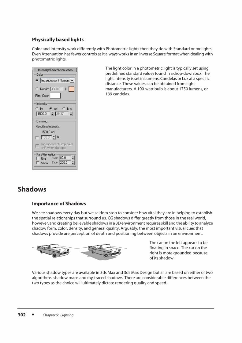
Physically based lights
Color and Intensity work differently with Photometric lights then they do with Standard or mr lights.
Even Attenuation has fewer controls as it always works in an Inverse Square format when dealing with
photometric lights.
Shadows
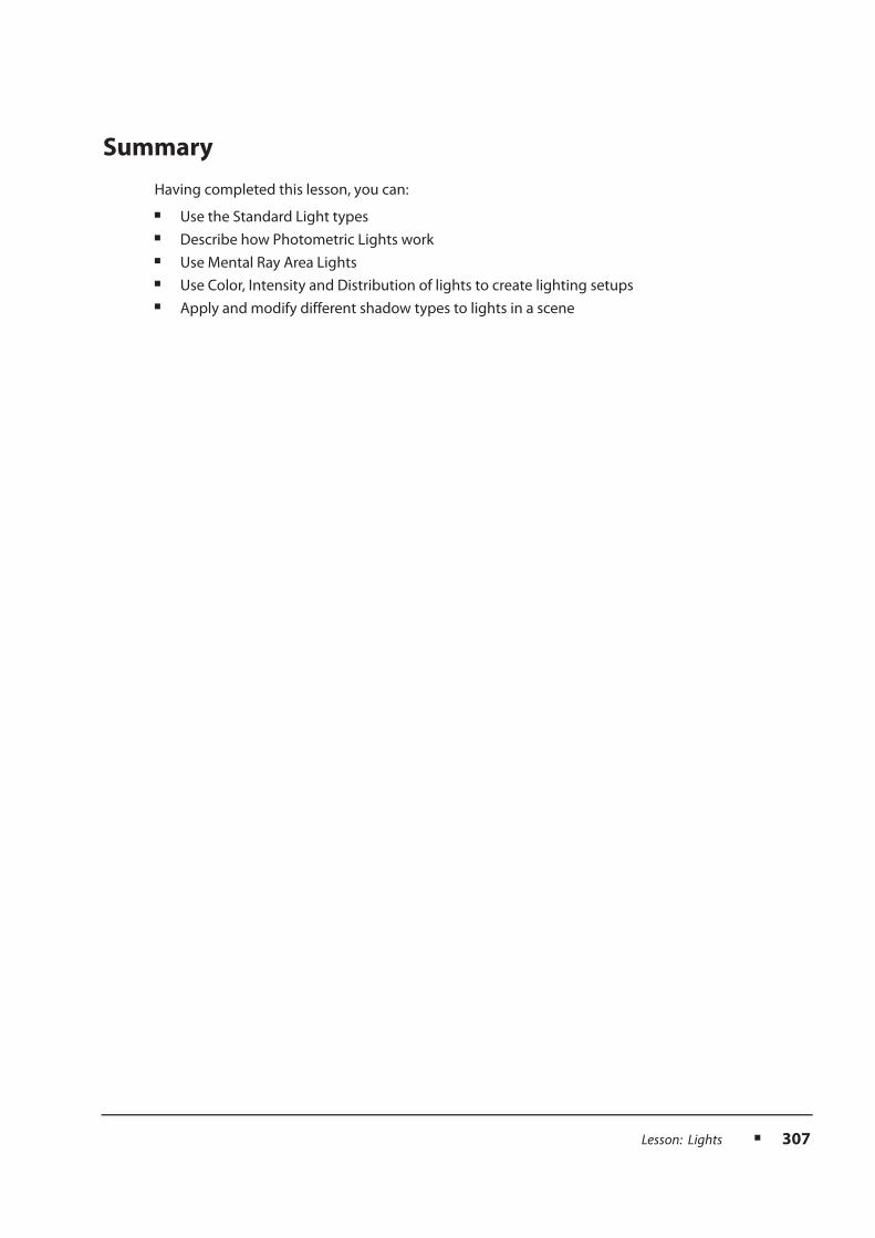
Importance of Shadows
We see shadows every day but we seldom stop to consider how vital they are in helping to establish
the spatial relationships that surround us. CG shadows differ greatly from those in the real world,
however, and creating believable shadows in a 3D environment requires skill and the ability to analyze
shadow form, color, density, and general quality. Arguably, the most important visual cues that
shadows provide are perception of depth and positioning between objects in an environment.
Various shadow types are available in 3ds Max and 3ds Max Design but all are based on either of two
algorithms: shadow maps and ray-traced shadows. There are considerable differences between the
two types as the choice will ultimately dictate rendering quality and speed.
The light color in a photometric light is typically set using
predefined standard values found in a drop-down box. The
light intensity is set in Lumens, Candelas or Lux at a specific
distance. These values can be obtained from light
manufacturers. A 100-watt bulb is about 1750 lumens, or
139 candelas.
The car on the left appears to be
floating in space. The car on the
right is more grounded because
of its shadow.

Lesson: Lights n 303
Shadow Maps
The shadow map method uses a bitmap that the renderer generates before final rendering. The
process is completely transparent and does not store any information on the hard drive. The bitmap
is then projected from the direction of the light. Shadow maps can be fast to calculate and can
produce soft-edged shadows. On the downside, they are not very accurate and do not take objects’
transparency or translucency into account.
Ray-Traced Shadows
Ray-traced shadows are generated by tracing the path of rays from a light source. They are more
accurate than shadow maps but generally produce hard-edged shadows. Because ray-traced
shadows are calculated without a map, you do not have to adjust resolution as you do for shadow-
mapped shadows, making them easier to set up. Ray-traced shadows take transparency and
translucency into account, and can even be used to generate shadows for wireframe objects.
More Shadow Types
There are other shadow types that you can use. Advanced ray-traced shadows are similar to ray-traced
shadows but provide better antialiasing control and can generate soft-edged shadows. Area shadows
simulate shadows cast by a light that has a surface or a volume as opposed to a point. Shadows of this
type tend to become more blurred with distance. Mental ray shadow maps are to be used with the
mental ray renderer.
Shadow map with soft edges. The shadowing
is uniform and does not recognize the
transparency of the glass.
Ray-traced shadow with hard edges. The
transparency of the glass is taken into account.
Advanced Ray Traced shadow Area shadow

304 n Chapter 9: Lighting
In addition to these shadow types, the shape and size of the light source will affect the sharpness of
the shadows.
Ray Traced Shadow from a point light source Ray Traced Shadow from a spherical light source

Lesson: Lights n 305
Exercise: Creating a Target Spot
1. Reset 3ds Max Design.
2. Open the file shadows.max.
The scene shows a wine glass on a flat
wooden surface.
3. Make sure the Perspective viewport is active
and then press the F9 key to render the scene.
The rendered scene looks flat for lack of
contrast. The lighting is uninteresting and the
absence of shadows makes for a weak
connection between the glass and the
tabletop.
4. Right-click the Front viewport to activate it.
5. On the Create panel, click the Lights button.
Make sure you have the Standard in the type
list selected.
6. Click mr Area Spot on the Object Type rollout.
7. In the Front viewport, click and drag from the
top-right corner onto the wine glass.
8. Activate the Perspective viewport and test-
render the scene again.
By default, in 3ds Max Design, the Spot light
casts shadows. The Hotspot and Falloff values
are very close, making a “theatre spotlight”
effect as the edge of the pool of light is
very crisp.
9. With the light selected, go to the Modify panel
and expand the Spotlight Parameters rollout.
10. Set the Hotspot/Beam value to 15.0 to
decrease the light cone, where the intensity
is at its maximum.

306 n Chapter 9: Lighting
11. Set the Falloff/Field value to 100.0 to increase
the overall diameter of the light so that the
Spot light encompasses more of the 3D
environment.
12. Render the Perspective viewport again.
13. With the light still selected, open the Area
Light Parameters rollout at the bottom of the
Modify panel.
14. Change the type to Disc, and the Radius
value to 50.0.
15. Render the Perspective viewport.
The shadow is blurred now, which would be
consistent with light emanating from a large
surface rather than a single point.
Lesson: Lights n 307
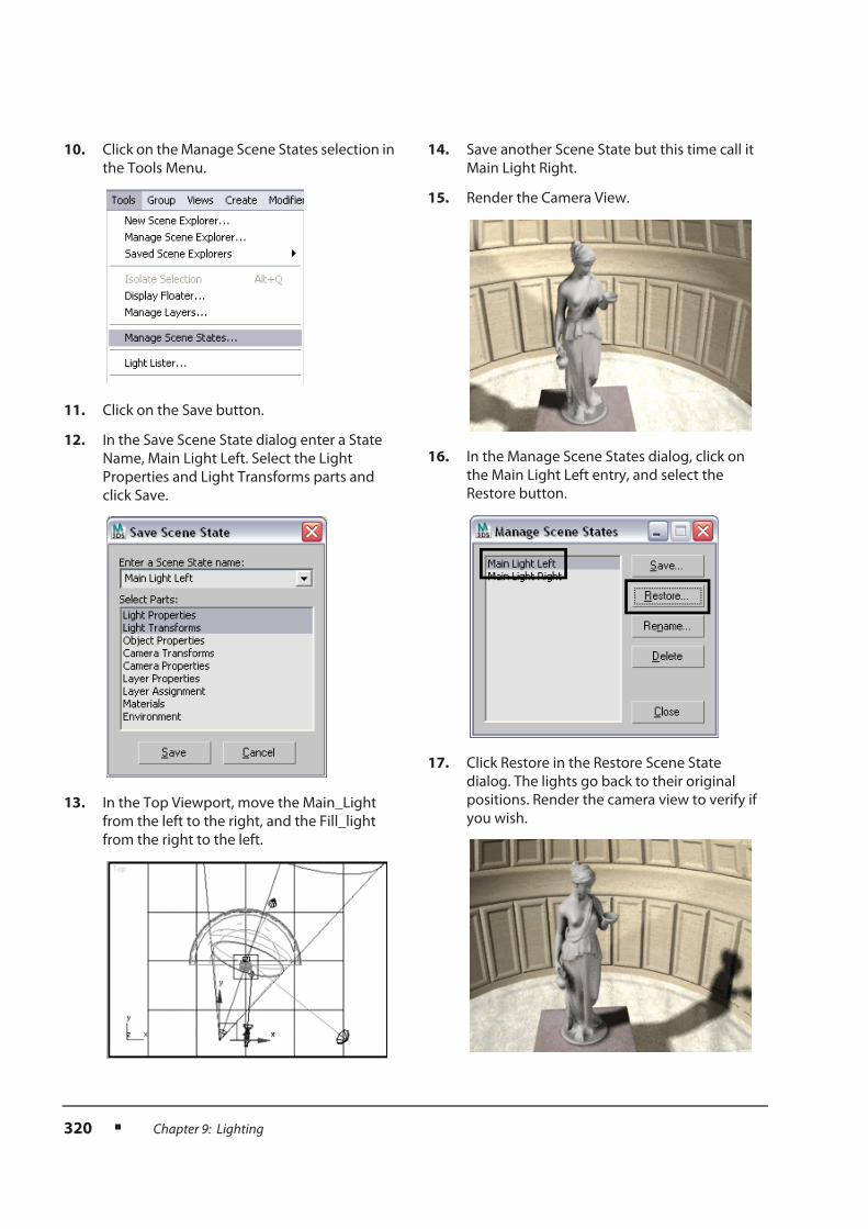
Summary
Having completed this lesson, you can:
n Use the Standard Light types
n Describe how Photometric Lights work
n Use Mental Ray Area Lights
n Use Color, Intensity and Distribution of lights to create lighting setups
n Apply and modify different shadow types to lights in a scene

308 n Chapter 9: Lighting
Lesson: Simple Lighting Setup
Overview
Lighting setups can be fairly complex, but in many situations a simple lighting setup will suffice. We
will look at a simple lighting setup called the three-point light setup.
Objective
After completing this lesson, you will be able to:
n Use the three point lighting system for simple lighting setups

Lesson: Simple Lighting Setup n 309
Three Point Lighting
As its name implies, the technique of three-point lighting uses three lights with very specific functions.
It is a technique that is firmly established in cinematography and is one of the foundations in CG
lighting as well. This technique emphasizes three-dimensional forms in a scene.
Rendered scene with default lighting Rendered scene with 3-point lighting
The Key Light
The key light is the main or dominant light in
the scene. It is often the only one that casts
shadows and is used as the primary light
source in the scene.
The Fill Light
The fill light functions primarily to control
shadow density. It is often not enough to
control the density of the main light’s
shadows. The fill light helps to remedy that
problem by softening the effect of shadows in
the scene. At the same time, it acts as a bounce
light, simulating or enhancing global
illumination. Typically, the fill light is less
intense than the key light.

310 n Chapter 9: Lighting
The Backlight (or Rim light)
The backlight’s sole purpose is to separate the
subject from the background, giving the scene
greater depth. It works by illuminating the
back of an object or character so that the
silhouette is easier to see.

Lesson: Simple Lighting Setup n 311
Exercise: Working with Three-Point Lighting
1. Reset 3ds Max Design.
2. Open the file 3-point_start.max.
3. With the Camera viewport active, press the
F9 key to render the scene.
The scene shows the rendering of a statue
based on 3ds Max’s default lighting. The
general mood is far from interesting, so you’ll
use the three-point lighting technique to
make the scene more appealing.
4. On the Create panel, click the Lights
button.
5. Make sure the Light type list is set to Standard.
6. Choose mr Area Spot from the Object Type
panel.
7. In the Front viewport, click and drag from the
top-left corner to the statue.
8. On the main toolbar, click the Move
button.
In the Top viewport, move the spotlight and
position it in the bottom-left corner of the
viewport.
9. On the Modify panel, rename the spotlight:
Main_Light.
Before you make adjustments to the main
light, you’ll create the fill light and backlight.
10. On the Create panel, under Lights, choose the
mr Area Spot again.
11. In the Front viewport, create a second light by
dragging it from the center-right of the
viewport to the statue.

312 n Chapter 9: Lighting
12. Using the Move tool, adjust the position of the
new spotlight in the Top viewport so that it’s
directed at the statue from roughly the
opposite direction of the main light, using the
camera vector as a mirror plane.
13. Rename the second light: Fill_Light.
14. Create one more spotlight in the Front
viewport, dragging from the top-center of the
viewport to the statue.
15. In the Top viewport, move the new spotlight
so that it’s directed at the statue from the
“northeast” direction.
16. Rename the light Backlight.
17. Select the Main_Light and go to the Modify
panel.
18. On the General Parameters rollout, verify that
Shadows are on the type set to mental ray
Shadow Map.
19. On the Spotlight Parameters rollout, set
Hotspot to 30.0 and Falloff to 100.0.
20. On the Shadow Map Parameters rollout, set
Size to 2048.
Increasing this values the shadow edges are of
better quality that the default settings allow.
21. Select the Fill_Light.
22. On the Intensity/Color/Attenuation rollout,
set the Multiplier value to 0.4.
This makes the fill light less intense than the
main light.
23. In the Far Attenuation group, turn on Use.
This causes the light intensity to fall off with
distance, based on Start/End distances you
specify.

Lesson: Simple Lighting Setup n 313
24. Adjust the Start/End Attenuation values so
that the light attenuates from the front of the
statue to the vault wall. Keep an eye on the
Top viewport for reference.
25. Select the Backlight.
26. On the Intensity/Color/Attenuation rollout,
set the Multiplier value to 0.6.
27. In the Far Attenuation group, turn on Use.
28. Adjust the Start/End Attenuation values so
that the light attenuates from the statue’s
head to its knees. Keep an eye on the Front
viewport for reference.
29. Render the Camera viewport.
Compare the rendering to the first test render
you created early in this exercise.
Rendered scene with 3-point lighting
Rendered scene with default lighting

314 n Chapter 9: Lighting
Summary
Having completed this lesson, you can:
n Use the three point lighting system for simple lighting setups

Lesson: Lighting Tools n 315
Lesson: Lighting Tools
Overview
Lighting setups can be fairly complex, but in many situations a simple lighting setup will suffice.
We will look at a simple lighting setup called the three-point light setup.
Objectives
After completing this lesson, you will be able to:
n Use the Light Lister to manage multiple lights
n Use the Manage Scene States dialog to save lighting setups
n Turn on and adjust final gather when appropriate in your lighting setups

316 n Chapter 9: Lighting
Light Lister
Light Lister is a dialog that lets you control a number of features for each light. It is a very useful tool
for managing multiple lights in your scene. You can easily change light parameters, such as Multiplier
values and shadow types, turn lights off and on, turn shadows off and on, and so on.
Manage Scene States
Although not specifically about lighting the Manage Scene State dialog bears some mention at this
point. In the dialog you can save two parameters which are related to lighting; Lighting Parameters
and Lighting transforms.

Lesson: Lighting Tools n 317
An example would be, In a simple 3 point light setup you could easily switch the main light and the fill
light by changing multipliers, and the Z height of the light so the main light is from the right side rather
than the left.
Before transforming the lights position, save a scene state. Transform the light positions, then save
another scene state.
Final Gather
Final gather is a setting used to control indirect illumination when using the mental ray renderer.
There are several controls which are accessible in the Render Window and the Render Setup Dialog.
Main Light on the left Main Light on the right
The bottom of the Render Window dialog contains the most important controls for final gather. Here
you can toggle final gather on/off, control the number of bounces and the precision of the final
gather calculation.

318 n Chapter 9: Lighting
A few points about final gather:
n When final gather is off your render will proceed quicker, but your shadows will generally be very
dark. Turning on final gather will lighten shadows and produce indirect illumination automatically.
n The more bounces you use the better the effect, although more than 3 bounces and the increased
effect is barely noticeable.
n Finally the precision of the calculation is generally set to draft until you are ready to do a final
render. Settings of low to medium are common even at final render stages.
In the Render Setup Dialog, the same controls appear as in the Render Windows dialog with an
additional number of controls which can be used to further refine your final gather setup.

Lesson: Lighting Tools n 319
Exercise: Using Lighting Tools
1. Open the file Light_Tools.max.
2. From the Tools menu, choose Light Lister.
3. On the Light Lister dialog, turn off Fill_Light
and Backlight.
4. Render the Camera viewport.
With only the key light lighting the scene, the
right side of the statue is drowned in black.
5. On the Light Lister, turn off Main_Light and
turn on Fill_Light.
6. Render the Camera viewport again.
The fill light provides ambient lighting for the
scene.
7. On the Light Lister, turn off Fill_Light and turn
on Backlight.
8. Render the Camera viewport.
The back light provides a subtle glow around
the head and shoulders that helps separate
the character from the background.
9. Turn on the Main_Light, Fill_Light, and
Backlight.
320 n Chapter 9: Lighting
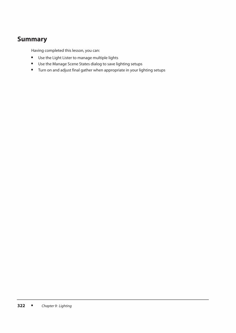
10. Click on the Manage Scene States selection in
the Tools Menu.
11. Click on the Save button.
12. In the Save Scene State dialog enter a State
Name, Main Light Left. Select the Light
Properties and Light Transforms parts and
click Save.
13. In the Top Viewport, move the Main_Light
from the left to the right, and the Fill_light
from the right to the left.
14. Save another Scene State but this time call it
Main Light Right.
15. Render the Camera View.
16. In the Manage Scene States dialog, click on
the Main Light Left entry, and select the
Restore button.
17. Click Restore in the Restore Scene State
dialog. The lights go back to their original
positions. Render the camera view to verify if
you wish.

Lesson: Lighting Tools n 321
18. Click on the Render Window Icon on the Main
toolbar.
19. At the bottom left of the Render Window
remove the check in the Final Gather
checkbox.
20. Click the Render button at the top right of the
Render Window dialog.
overall the lighting will be darker and the
shadows will not be brightened by indirect
illumination.
21. Turn on final gather again and this time
change the bounces to 1.
22. Render again.
This time the scene is washed out slightly as
too much light is bouncing around.
23. Return the Bounces back to 0.
24. Change the Final Gather Precision to Medium.
25. Render the scene again.
Note how much longer the scene takes to
render, at this resolution and the type of
lighting setup, there is very little gained by the
increase in precision.
322 n Chapter 9: Lighting
Summary
Having completed this lesson, you can:
n Use the Light Lister to manage multiple lights
n Use the Manage Scene States dialog to save lighting setups
n Turn on and adjust final gather when appropriate in your lighting setups

Lesson: Light in the Real World n 323
Lesson: Light in the Real World
Overview
Light is a very interesting phenomenon. We see it every day, it surrounds us, interacts with us, and yet
we understand very little about it, as its physical properties rely on complex formulas. As an artist, you
need to understand the subtleties of light without delving too deeply into its complex nature. The key
to that effect is to study light around you, understand how it is affecting its surroundings, and try to
emulate that in different 3D environments.
Objectives
After completing this lesson, you will be able to:
n Apply how light works in the real world to a CG scene
n Describe the effect of color bleed in CG Lighting
n Use Ambient Occlusion to add detail to the render

324 n Chapter 9: Lighting
Light in the Real World
Light Sources
When lighting a scene, it is important to define how many light sources affect the environment. This
is easier said than done. In any scene, there may be light sources that you may not have noticed that
are a crucial part of the overall lighting. Therefore, you may need to place more lights than anticipated,
based on your study of the scene. Bear in mind that all scenes are different and that a lighting scenario
in one may not work in another.
Consider the scene below: assuming there’s no artificial lighting inside the room, it’s easy to assume
that we are dealing with a single light source (the sun) coming from outside, where in fact, there can
be easily three to four lights illuminating the scene.
Sunlight
The first light and most prominent is sunlight itself. This is created using a direct light or a direct-based
light system such as sunlight or daylight.
Scene without any lights (default lighting). Scene lit with 3 light sources. The final render is a sum
of the effects discussed below.
A direct light casting parallel rays. When Raytraced shadows are on and final gather off,
light entering into a room will produce a bright area
in an overall dark space.

Lesson: Light in the Real World n 325
Another light to consider is the bouncing light resulting from the main light bouncing off surfaces.
Light reflects in the real world, some of its energy is absorbed but the rest is reflected onto other
surfaces taking with it some of the properties of the bouncing surface. With the mental ray render this
bouncing of light is handled through indirect illumination (final gather).
The third and last light needed for this scene is the Skylight (ambient lighting coming from outside).
That’s an important piece in addition to the sunlight itself. The light coming from the windows is an
important contributor to the scene. The window panes become effectively light sources, portals if you
will, to the ambient lighting outside.
Light rays coming from the sun bounce off the floor and
illuminate the walls and ceiling.
turning on final gather in the mental ray render will
generally give you excellent results for bounced light.
The window panes become portals for the ambient
light coming from outside.
a Sky Portal object allows you to simulate ambient
light entering a space through an opening.

326 n Chapter 9: Lighting
When you combine the effects of all three lights the interior space is properly illuminated.
Color Bleed
Color Bleed is an important part of CG lighting as it emulates real-world situations. When a light
bounces off a surface, it collects some of the properties of that surface, including color information.
Therefore, the bounce light is tinted with the color of the bounce surface.
The effect can be simulated and adjusted in a number of ways, by changing the color of a fill light or
by using some of the advanced lighting features found in Light Tracing, Radiosity and Mental Ray.
Ambient Occlusion
Ambient Occlusion is a technique developed by ILM (Industrial Light & Magic) to simulate the effect
of Global Lighting without the cost of full global illumination. The technique in fact, relies on a shader
(material component) to simulate a light effect. Ambient Occlusion (often referred to as a dirt map)
works by determining the proximity of objects to calculate dark areas between them. An ambient
Occlusion map is often a black & white map that can be calculated directly at render time or as a
separate “pass” to be composited over the diffuse render at a later time.
Scene illuminated without the effect of color bleed Bouncing light (fill omni light) carrying the effect of
the green color from the tabletop.

Lesson: Light in the Real World n 327
The effect of Ambient Occlusion on a scene can have a great effect on objects in close proximity.
Notice how the details of the crates came alive.
How Ambient Occlusion Works...
Ambient Occlusion is about calculating how much ambient light a surface point is likely to receive. In
an office space for example, a surface point under the desk would end up much darker than a surface
point on the desktop, although other objects on the desk may affect that surface point too.
Ambient Occlusion starts from your position looking at the scene. Every single point visible to your eye
gets calculated in the following way: A number of rays are cast from that point in a randomized,
hemispherical way, out to do “hit-tests” on the rest of the scene.
Some rays collide with other objects, some don’t. The surface point is then shaded by a ratio of hit-rays.
If only a few rays hit obstacles, the shading is light. If most rays hit obstacles, the shading of that point
is dark.

328 n Chapter 9: Lighting
The Ambient Occlusion Shader
The Ambient Occlusion shader is typically something you can easily activate in the Arch & Design or
ProMaterials.
Ambient Occlusion is included in the Special Effects rollout in the Arch & Design material.
In ProMaterials Ambient Occlusion has its own rollout.
The most important are the “Samples” and “Max distance” values.
The Samples value determines the number of rays cast from any given surface point. The default is 16
and may yield a grainy look to the rendering. A value between 32 and 64 is usually preferred. Higher
values yield better results but can increase render time.

Lesson: Light in the Real World n 329
The Max distance value determines how far the rays travel before they die away. A value of 0 means
the rays travel indefinitely. A value other than zero would restrict the distance traveled to that amount.
If an obstacle is reached within that distance, then the surface point is occluded. If not, then that ray is
considered “non-occluding”.
The Effects of Ambient Occlusion
As mentioned, Ambient Occlusion is used as an “add-on” effect, to pump up the illumination of a
scene by taking into account cracks and contact shadow, all this without the cost of full global
illumination calculation.
Rays are limited to travel a specific distance. In this
case the distance is short and the rays do not collide
with any obstacles, therefore, the surface point is not
shaded.
Rays are not limited (Max distance=0) and they keep
traveling indefinitely. In this case, 2 out 5 rays collide
with an obstacle and the surface point is moderately
shaded.
Scene lit with default lighting. The result is very
unappealing.
Scene with no lights and using Ambient Occlusion.
Already, the effect is far more realistic. The various
surfaces of the car and between the car and the
ground occlude one another to create a realistic
render.

330 n Chapter 9: Lighting
Summary
Having completed this lesson, you can:
n Apply how light works in the real world to a CG scene
n Describe the effect of color bleed in CG Lighting
n Use Ambient Occlusion to add detail to the render
Same scene (with default lighting0 as above but
using textures instead of a white material. The effect
is just as unappealing without proper lighting.
Ambient Occlusion makes this rendering far more
appealing than the one on the left.

Lesson: Simulating the Sun n 331
Lesson: Simulating the Sun
Overview
Sunlight, whether it is simply used to illuminate an exterior scene or when it enters an interior space
providing interesting and potentially dramatic lighting effects, has specific tools in 3ds Max or 3ds Max
Design to simulate its effects.
Objectives
After completing this lesson, you will be able to:
n Use various methods to simulate the sun and sky in a 3D scene
n Describe the use of a Sky Portal

332 n Chapter 9: Lighting
Simulating the Sun and Sky
Because of the distance of the sun to the earth, the sun is modeled as a parallel light source, which
makes the incident direction of sunlight constant over all surfaces in the scene. Even though the sun
can be viewed as a point light far, far away, it is not convenient to use an omni light or even a spot light
to simulate the sun (imagine placing either of these lights at 150 million kilometers from your scene).
For that reason, the sun in most 3D applications is based on a direct light that cast parallel rays.
The Sunlight System
The Sunlight system uses light in a system that follows the geographically correct angle and
movement of the sun over the earth at a given location. You can choose location, date, time, and
compass orientation. You can also animate the date and time. This system is suitable for shadow
studies of proposed and existing structures. In addition, you can animate Latitude, Longitude, North
Direction, and Orbital Scale. At its core, the Sunlight System is based on a standard Direct light.
An omni or a spotlight placed near the scene
produce diverging shadows which is not
accurate for a sun representation.
Using a direct light or a direct-based lighting
system, the rays and the shadows run parallel,
simulating the sun’s behavior based on its
great distance from the earth.

Lesson: Simulating the Sun n 333
The Sunlight system is found in the Create tab of the Command Panel by clicking on the systems icon.
A Sunlight system is typically created in the top view, first with a click and drag to define a rose
compass (North direction) and then an additional drag to define the orbital scale (position of the “sun”
in the form of a direct light). Once created, these parameters can then be edited in the Motion panel.
The Daylight System
A Daylight system has many similarities to the Sunlight system, in that it is created exactly the same
way in the viewport and the properties such as geographic location, date and time of day are identical
in the Motion panel. However the Daylight System has many advantages over the Sunlight system,
since it actually combines the Sunlight system with ambient light (Skylight) and a Background Map for
the sky and ground.
In addition, the Daylight system uses mental ray-specific lights and it can also use photometric light
data to feed the sunlight and skylight channels.
As with the Skylight system you will find the Daylight system in the Create tab of the Command
Panel by clicking on the systems icon.

334 n Chapter 9: Lighting
Editing a Daylight System
The Process of Creating a Daylight system is similar to a Sunlight system except you will be
prompted along the way for specific responses. First you will be prompted to use mr Photographic
Exposure Control.
Next you will be prompted to use the mr Physical Sky as a background map.
It’s generally a good idea to accept these defaults.
When you wish to edit a Daylight system there are a few places where you will need to look. The first
thing to know is that a Daylight system has many components, two of which are immediately
displayed when you look for the object in the Select from Scene dialog.
The Compass object is a helper which controls the position and rotation of the entire system, while
the Daylight object is a special type of group called an assembly.

Lesson: Simulating the Sun n 335
When you select the Daylight system and go to the Motion Panel you have access to geographic
data to set the sunlight position.
The Modify tab provides you access to the light information.

336 n Chapter 9: Lighting
mr Physical Sky
In the Light Lister the lights associated with a Daylight system are listed separately.
As soon as you place a Daylight system in your scene when mental ray is active, a warning appears
suggesting you use the mr Physical Sky as a background. When you accept this default the mr
Physical Sky will be placed in your Environment dialog.

Lesson: Simulating the Sun n 337
This special map type creates a sky gradient that changes based on the time of day. It has a direct
influence on the reflections calculated in the scene and you are encouraged to use it in conjunction
with the Daylight System.
Note that the mr Physical sky will also render an image of the sun if it appears in the view
of the camera.
Exposure Control
Scene rendered at 2pm same scene rendered at 7pm
Exposure control is, as its name would suggest to photographers, a method of controlling the
exposure in a rendering. mr Photographic Control is the preferred method to use with mental ray.
There are two basic methods of controlling the exposure control using this tool; Exposure Value (EV)
and Photographic Exposure.
Exposure value is a simple numeric value, the default of 15.0 represents a good value for exterior
sunlight. Selecting a preset value for an interior rendering will change this to 2.0. Higher values will
create darker images.
Photographic values might be preferable for individuals who are more familiar with photographic
settings. Here Shutter Speed, Aperture, and Film Speed can be adjusted as you would if you were
taking a picture with a camera.

338 n Chapter 9: Lighting
mr Sky Portal
mr Sky Portal is a tool used like a light (it is found in the Photometric Lights panel) and its purpose is
to concentrate Final Gather rays in an area that you define, usually a window or a door opening.
You create the sky portal object with a click & drag. Its shape is rectangular. It also has a direction
defined by a small arrow. Although you can create in any view and then reorient and resize it, it is
best to use it in conjunction with the Autogrid feature, so you can automatically align to any face in
your scene.
Lesson: Simulating the Sun n 339
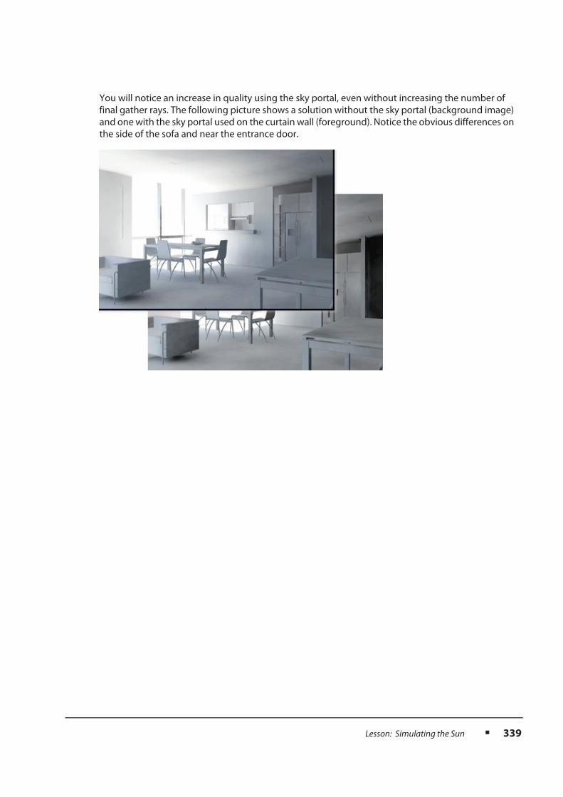
You will notice an increase in quality using the sky portal, even without increasing the number of
final gather rays. The following picture shows a solution without the sky portal (background image)
and one with the sky portal used on the curtain wall (foreground). Notice the obvious differences on
the side of the sofa and near the entrance door.

340 n Chapter 9: Lighting
Exercise: Lighting the Courtyard
1. Open the file Courtyard_Light_Start.max.
2. Make the Top viewport active.
3. From the Create menu, select Lights >
Daylight System.
4. In the Daylight Object Creation dialog, select
Yes to turn on mr Photographic Exposure
Control.
5. Click and drag a point in the approximate
center of the courtyard to create the compass
Rosetta portion of the Daylight System. The
Mental Ray Sky dialog appears.
6. Click Yes in the dialog to add an mr Physical
Sky environment map. A daylight system is
created.
7. Move the mouse and click to finish positioning
the daylight system.
8. In the Motion Tab of the Command Panel, set
the Hours to 11.

Lesson: Simulating the Sun n 341
9. Make sure the Camera03 viewport is current
then, click the Render Production button to
Render the Camera03 view.
The image is quite dark even in the area lit by
the sun. An adjustment to the exposure
control is in order.
10. In the Render Window click on the
Environment and Effects dialog button.
11. Change the Exposure Value (EV) to 12.
12. Click the Render Preview button. A small
rendered image appears.
There is an improvement in the brightness of
the sunny areas of the courtyard.
13. Click the Render button in the Render Window
dialog to Render the Camera03 view again.
The scene is considerably brighter now, but
the shadow areas are still extremely dark. You
will change this using Final Gather.

342 n Chapter 9: Lighting
14. At the bottom left of the Render Window
dialog click in the Final Gather checkbox to
activate it.
15. In the lower right of the Render Window
dialog use the Final Gather Precision slider
to set the Precision to Draft.
16. Render the Camera03 view again.
The image has a good quality, but the dark
areas are still a bit too dark.
17. In the Rendering Menu, select the RAM Player.
18. In the RAM Player, select the Open last
Rendered Image in Channel A button. and
click OK to accept the default in the RAM
Player Configuration dialog.
19. In the Lower left of the Render Window
change the Bounces to 2. This will make each
individual light ray bounce a few more times
before dying away, and help illuminate the
areas in the shadows.

Lesson: Simulating the Sun n 343
20. Render the Camera03 view.
21. In the RAM Player dialog, select the Open last
Rendered Image in Channel B button.
22. In the RAM Player you can now compare the
before (Bounces = 0) and after (Bounces=2)
images by sliding the arrow along the top of
the image.
23. Save your file.

344 n Chapter 9: Lighting
Summary
Having completed this lesson, you can:
n Use various methods to simulate the sun and sky in a 3D scene
n Describe the use of a Sky Portal
Chapter Summary
Having completed this chapter, you can:
n Create and manipulate lights
n Create a simple 3 point lighting setup
n Use lighting tools
n Apply how light works in the real world appears to your CG Scenes
n Simulate the sun in a CG scene


