NARDA Measurements in the vicinity of fixed wireless transmitters

Seattle City Light
WORK PRACTICE
Standard Number: Superseding:
Effective Date: Page:
0095.04 June 26, 2020 October 16, 2020 1 of 28
Standards Coordinator John Shipek
Standards Supervisor John Shipek
Unit Director Andrew Strong
Working in the Vicinity of Wireless Communications Antennas
Table of Contents
1. Scope . . . . . . . . . . . . . . . . . . . . . . . . . . . . . . . . . . . . . . . . . . . . . . . . . . . . . . . . . . . . . . . . . . . . . . . . . . . . . . . . . 2 2. Application . . . . . . . . . . . . . . . . . . . . . . . . . . . . . . . . . . . . . . . . . . . . . . . . . . . . . . . . . . . . . . . . . . . . . . . . . . . . 2 3. Definitions . . . . . . . . . . . . . . . . . . . . . . . . . . . . . . . . . . . . . . . . . . . . . . . . . . . . . . . . . . . . . . . . . . . . . . . . . . . . . 2 4. Required Personal Protective Equipment (PPE) . . . . . . . . . . . . . . . . . . . . . . . . . . . . . . . . . . . . . . 7 5. Required Tools and Equipment . . . . . . . . . . . . . . . . . . . . . . . . . . . . . . . . . . . . . . . . . . . . . . . . . . . . . . . 8 6. Wireless Communications Antenna Configurations . . . . . . . . . . . . . . . . . . . . . . . . . . . . . . . . . . . 9
6.1 Introduction . . . . . . . . . . . . . . . . . . . . . . . . . . . . . . . . . . . . . . . . . . . . . . . . . . . . . . . . . . . . . . . . . . . . . . 9 6.2 Small Wireless Facilities Below Distribution Conductors . . . . . . . . . . . . . . . . . . . . . . . 11 6.3 Small Wireless Facilities on a Guy Stub Pole . . . . . . . . . . . . . . . . . . . . . . . . . . . . . . . . . . 12 6.4 Small Wireless Facilities Below a Streetlight Bracket Arm, Co-located . . . . . . . . . 13 6.5 Small Wireless Facilities Above a Streetlight Bracket Arm, Co-located . . . . . . . . 14 6.6a Macrocell on Secondary Service Poles . . . . . . . . . . . . . . . . . . . . . . . . . . . . . . . . . . . . . . . . . 15 6.6b Macrocell on Secondary Service Poles, Alternate Disconnect Switch . . . . . . . . . . 16 6.7 Macrocell on a Distribution Pole . . . . . . . . . . . . . . . . . . . . . . . . . . . . . . . . . . . . . . . . . . . . . . . . 17 6.8 Macrocell on a Transmission Pole . . . . . . . . . . . . . . . . . . . . . . . . . . . . . . . . . . . . . . . . . . . . . 18 6.9 AMI Repeater on a Wood Pole, 3-ft Bracket Arm . . . . . . . . . . . . . . . . . . . . . . . . . . . . . . . . . . 19 6.10 AMI Repeater on a Streetlight Mast . . . . . . . . . . . . . . . . . . . . . . . . . . . . . . . . . . . . . . . . . . . . . . . 20 6.11 AMI Repeater on a Streetlight Pole . . . . . . . . . . . . . . . . . . . . . . . . . . . . . . . . . . . . . . . . . . . . . . . 21 6.12 AMI Collector Above Secondary Conductors . . . . . . . . . . . . . . . . . . . . . . . . . . . . . . . . . . . . . . 22 6.13 AMI Collector Above Primary Conductors . . . . . . . . . . . . . . . . . . . . . . . . . . . . . . . . . . . . . . . . . 23
7. General Steps for Working in the Vicinity of Wireless Communications Antennas . . 24 8. Detailed Steps for Working in the Vicinity of a Strand-Mount Antenna
(all except Wi-Fi hotspot), Example . . . . . . . . . . . . . . . . . . . . . . . . . . . . . . . . . . . . . . . . . . . . . . . . . . 25 9. Detailed Steps for Working in the Vicinity of a Strand-Mount Wi-Fi
Hotspot, Example . . . . . . . . . . . . . . . . . . . . . . . . . . . . . . . . . . . . . . . . . . . . . . . . . . . . . . . . . . . . . . . . . . . . 27 10. References . . . . . . . . . . . . . . . . . . . . . . . . . . . . . . . . . . . . . . . . . . . . . . . . . . . . . . . . . . . . . . . . . . . . . . . . . . 27 11. Sources . . . . . . . . . . . . . . . . . . . . . . . . . . . . . . . . . . . . . . . . . . . . . . . . . . . . . . . . . . . . . . . . . . . . . . . . . . . . . . 28
Seattle City Light WORK PRACTICE Working in the Vicinity of Wireless Communications Antennas
Standard Number: Superseding:
Effective Date: Page:
0095.04 June 26, 2020 October 16, 2020 2 of 28
1. Scope
This work practice identifies the appropriate steps for safely working in the vicinity of wireless communications antennas adjacent to or attached to electric power line structures.
This work practice:
Identifies wireless communications antenna configurations that might be encountered in the public right-of-way.
Provides general steps for addressing these situations. Provides, as an example, specific steps for working near an antenna installed on a
communications strand. Provides, as an example, specific steps for working near a Wi-Fi hotspot antenna
(“Wi-Fi hotspot”) installed on a communications strand.
Also, this work practice provides definitions of important radio frequency (RF)-related terms and explains the hazards of RF energy to provide better context.
Some AMI collector antennas share the same visual profile, RF output power, and mounting requirements as AMI repeater antennas. These collector antennas shall be treated the same as repeater antennas.
Working in the vicinity of wireless communications antennas located on private property is outside the scope of this practice.
Working in the vicinity of “comm towers” (microwave antenna installations) is outside the scope of this practice.
Specific operating instructions, maintenance and calibration of personal RF exposure monitors are outside the scope of this practice.
2. Application
This work practice is for qualified Seattle City Light (SCL) electrical line workers and communications technicians who work in the vicinity of wireless communications antennas.
3. Definitions
AMI: AMI is the abbreviation for advanced metering infrastructure. SCL has only ever installed AMI wireless antennas. As of 2020, PSE is replacing its outdated Automated Meter Reading (AMR) wireless antennas with more-modern AMI units. For the purpose of this standard, the expression “PSE AMI wireless antenna” could also mean a PSE AMR wireless antenna.
AMI Collector Antenna (“AMI Collector”): AMI collectors are wireless antenna facilities used in Advanced Metering Infrastructure (AMI) networks with the function of providing radio coverage to a large area of AMI compatible, gas and electric meters. A collector differs from an AMI repeater antenna by offering the backbone of coverage area and high efficiency output. See AMI Repeater.
AMI Repeater Antenna (“AMI Repeater”): AMI repeaters are low-powered antennas that provide coverage to smaller geographic areas, supplementing the AMI/AMR larger network. These antennas help complement or stretch collector antenna coverage. AMI repeaters are also known as AMI routers. See AMI Collector and Figure 3c.
AMR: AMR is the abbreviation for automated meter reading a system exclusive of PSE. See AMI.
Seattle City Light WORK PRACTICE Working in the Vicinity of Wireless Communications Antennas
Standard Number: Superseding:
Effective Date: Page:
0095.04 June 26, 2020 October 16, 2020 3 of 28
Co-Located: The attachment by a third party on SCL utility infrastructure for the purpose of providing telecommunications services. A co-located streetlight pole is designed with a baffle inside that separates SCL streetlight electric service (governed by the National Electrical Safety Code) from customer electric service (governed by the National Electrical Code).
Distributed Antenna System (DAS) Equipment: Obsolete term. See small wireless facilities.
Exposure Limits, General Population: General Population exposure limits apply to those situations in which persons may not be aware of the presence of electromagnetic energy, where exposure is not employment-related, or where persons cannot exercise control over their exposure.
Exposure Limits, Occupational: Occupational exposure limits apply to situations in which persons are exposed, as a consequence of their employment, have been made fully aware of the potential for exposure, and can exercise control over their exposure.
Macrocell Antenna (“macrocell”): A macrocell is a wireless antenna used in cellular networks with the function of providing radio coverage to a large area of mobile network access. A macrocell differs from a small wireless facility or strand-mount wireless antenna by offering the backbone of coverage area and high-efficiency output. Traditional macrocell towers have a coverage area that spans several miles.
Non-Ionizing Radiation: “Ionization” is a process by which electrons are stripped from atoms and molecules. This process can produce molecular changes that can lead to damage in biological tissue, including effects on DNA, the genetic material of living organisms. This process requires interaction with high levels of electromagnetic energy. Those types of electromagnetic radiation with enough energy to ionize biological material include X-radiation and gamma radiation. Therefore, X-rays and gamma rays are examples of ionizing radiation.
The energy levels associated with RF and microwave radiation, on the other hand, are not great enough to cause the ionization of atoms and molecules, and RF energy is, therefore, a type of non-ionizing radiation. Other types of non-ionizing radiation include visible and infrared light. Often the term “radiation” is used, colloquially, to imply that ionizing radiation (radioactivity), such as that associated with nuclear power plants, is present. Ionizing radiation should not be confused with the lower-energy, non-ionizing radiation with respect to possible biological effects, since the mechanisms of action are quite different.
All the antennas depicted in this work practice are of the non-ionizing radiation type.
Non-Ionizing Electromagnetic Radiation (NIER) Report: When a customer applies to Joint Use Engineering to attach a wireless communications antenna, the customer is required to submit a NIER report reviewed, approved and endorsed by a radio frequency engineer licensed in Washington State. The purpose of the report is to determine if the wireless site meets the FCC standard for RF exposure of occupational and general population exposures. If the site poses an occupational hazard as demonstrated in the report, signage and a disconnect switch must be installed.
Personal RF Exposure Monitors: Small clip-on devices that are used to warn workers when they are in the presence of RF energy that approaches or exceeds applicable limits. Personal monitors alert workers when preset RF threshold levels are present; the workers are then able to remove themselves from the risk area and move to an area where the alarm thresholds of the monitor are not exceeded. See Section 5.
Seattle City Light WORK PRACTICE Working in the Vicinity of Wireless Communications Antennas
Standard Number: Superseding:
Effective Date: Page:
0095.04 June 26, 2020 October 16, 2020 4 of 28
Power Density: Power density is defined as power per unit area. It is commonly expressed in terms of milliwatts per square centimeter (mW/cm2). Power densities in the order of 100 mW/cm2 or more can clearly result in the heating of biological tissue and an increase in body temperature. Tissue damage in humans could occur during exposure to high RF levels because of the body’s inability to cope with or dissipate the excessive heat that could be generated.
Under certain conditions, exposure to RF energy at power density levels of 1-10 mW/cm2 and above can result in measurable heating of biological tissue (but not necessarily tissue damage). The extent of this heating would depend on several factors including radiation frequency; size, shape, and orientation of the exposed object; duration of exposure; environmental conditions; and efficiency of heat dissipation.
The General Population maximum permissible exposure (MPE) limit is 1 mW/cm2.
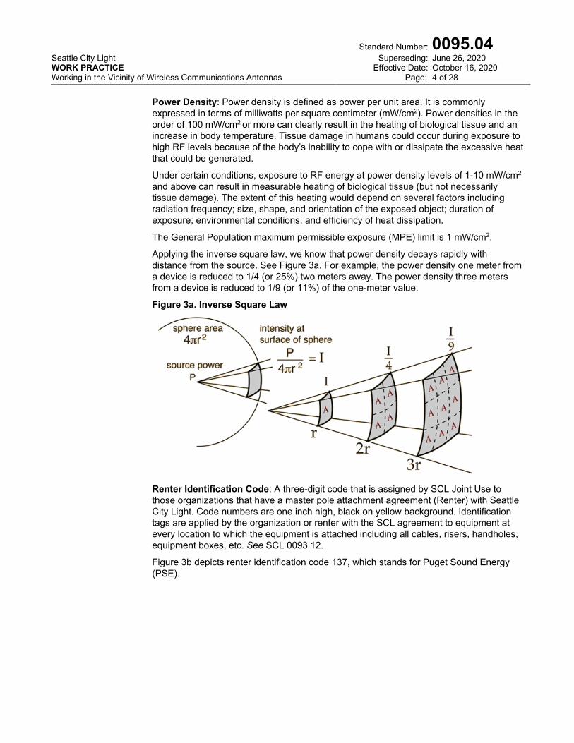
Applying the inverse square law, we know that power density decays rapidly with distance from the source. See Figure 3a. For example, the power density one meter from a device is reduced to 1/4 (or 25%) two meters away. The power density three meters from a device is reduced to 1/9 (or 11%) of the one-meter value.
Figure 3a. Inverse Square Law
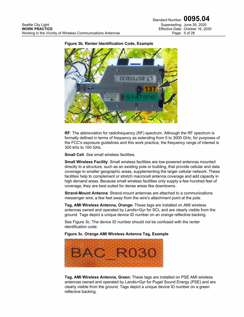
Renter Identification Code: A three-digit code that is assigned by SCL Joint Use to those organizations that have a master pole attachment agreement (Renter) with Seattle City Light. Code numbers are one inch high, black on yellow background. Identification tags are applied by the organization or renter with the SCL agreement to equipment at every location to which the equipment is attached including all cables, risers, handholes, equipment boxes, etc. See SCL 0093.12.
Figure 3b depicts renter identification code 137, which stands for Puget Sound Energy (PSE).
Seattle City Light WORK PRACTICE Working in the Vicinity of Wireless Communications Antennas
Standard Number: Superseding:
Effective Date: Page:
0095.04 June 26, 2020 October 16, 2020 5 of 28
Figure 3b. Renter Identification Code, Example
RF: The abbreviation for radiofrequency (RF) spectrum. Although the RF spectrum is formally defined in terms of frequency as extending from 0 to 3000 GHz, for purposes of the FCC's exposure guidelines and this work practice, the frequency range of interest is 300 kHz to 100 GHz.
Small Cell: See small wireless facilities.
Small Wireless Facility: Small wireless facilities are low-powered antennas mounted directly to a structure, such as an existing pole or building, that provide cellular and data coverage to smaller geographic areas, supplementing the larger cellular network. These facilities help to complement or stretch macrocell antenna coverage and add capacity in high demand areas. Because small wireless facilities only supply a few hundred feet of coverage, they are best suited for dense areas like downtowns.
Strand-Mount Antenna: Strand-mount antennas are attached to a communications messenger wire, a few feet away from the wire’s attachment point at the pole.
Tag, AMI Wireless Antenna, Orange: These tags are installed on AMI wireless antennas owned and operated by Landis+Gyr for SCL and are clearly visible from the ground. Tags depict a unique device ID number on an orange reflective backing.
See Figure 3c. The device ID number should not be confused with the renter identification code.
Figure 3c. Orange AMI Wireless Antenna Tag, Example
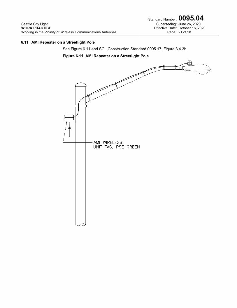
Tag, AMI Wireless Antenna, Green: These tags are installed on PSE AMI wireless antennas owned and operated by Landis+Gyr for Puget Sound Energy (PSE) and are clearly visible from the ground. Tags depict a unique device ID number on a green reflective backing.
Seattle City Light WORK PRACTICE Working in the Vicinity of Wireless Communications Antennas
Standard Number: Superseding:
Effective Date: Page:
0095.04 June 26, 2020 October 16, 2020 6 of 28
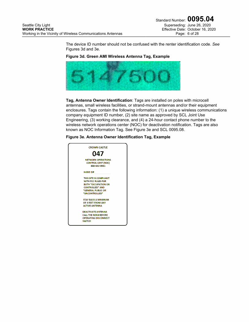
The device ID number should not be confused with the renter identification code. See Figures 3d and 3e.
Figure 3d. Green AMI Wireless Antenna Tag, Example
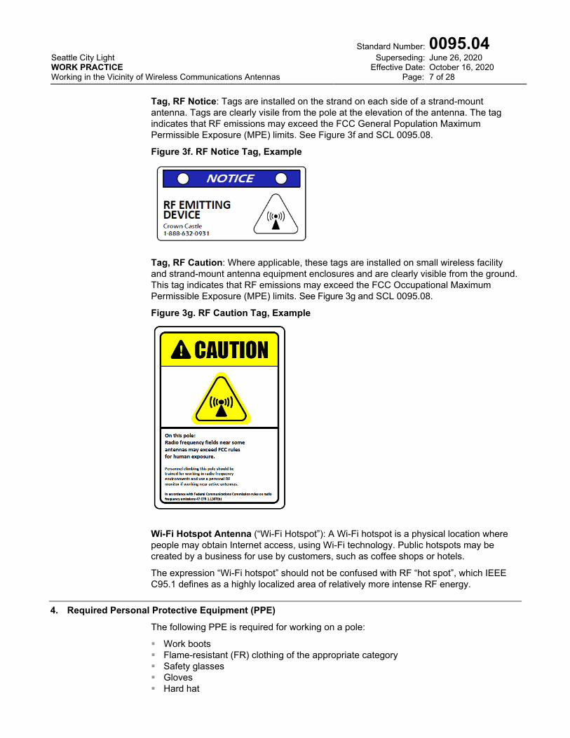
Tag, Antenna Owner Identification: Tags are installed on poles with microcell antennas, small wireless facilities, or strand-mount antennas and/or their equipment enclosures. Tags contain the following information: (1) a unique wireless communications company equipment ID number, (2) site name as approved by SCL Joint Use Engineering, (3) working clearance, and (4) a 24-hour contact phone number to the wireless network operations center (NOC) for deactivation notification. Tags are also known as NOC Information Tag. See Figure 3e and SCL 0095.08.
Figure 3e. Antenna Owner Identification Tag, Example
Seattle City Light WORK PRACTICE Working in the Vicinity of Wireless Communications Antennas
Standard Number: Superseding:
Effective Date: Page:
0095.04 June 26, 2020 October 16, 2020 7 of 28
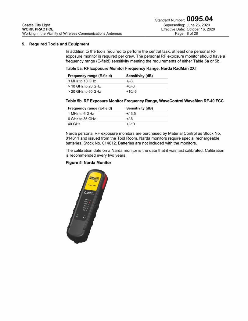
Tag, RF Notice: Tags are installed on the strand on each side of a strand-mount antenna. Tags are clearly visile from the pole at the elevation of the antenna. The tag indicates that RF emissions may exceed the FCC General Population Maximum Permissible Exposure (MPE) limits. See Figure 3f and SCL 0095.08.
Figure 3f. RF Notice Tag, Example
Tag, RF Caution: Where applicable, these tags are installed on small wireless facility and strand-mount antenna equipment enclosures and are clearly visible from the ground. This tag indicates that RF emissions may exceed the FCC Occupational Maximum Permissible Exposure (MPE) limits. See Figure 3g and SCL 0095.08.
Figure 3g. RF Caution Tag, Example
Wi-Fi Hotspot Antenna (“Wi-Fi Hotspot”): A Wi-Fi hotspot is a physical location where people may obtain Internet access, using Wi-Fi technology. Public hotspots may be created by a business for use by customers, such as coffee shops or hotels.
The expression “Wi-Fi hotspot” should not be confused with RF “hot spot”, which IEEE C95.1 defines as a highly localized area of relatively more intense RF energy.
4. Required Personal Protective Equipment (PPE)
The following PPE is required for working on a pole:
Work boots Flame-resistant (FR) clothing of the appropriate category Safety glasses Gloves Hard hat
Seattle City Light WORK PRACTICE Working in the Vicinity of Wireless Communications Antennas
Standard Number: Superseding:
Effective Date: Page:
0095.04 June 26, 2020 October 16, 2020 8 of 28
5. Required Tools and Equipment
In addition to the tools required to perform the central task, at least one personal RF exposure monitor is required per crew. The personal RF exposure monitor should have a frequency range (E-field) sensitivity meeting the requirements of either Table 5a or 5b.
Table 5a. RF Exposure Monitor Frequency Range, Narda RadMan 2XT
Frequency range (E-field) Sensitivity (dB) 3 MHz to 10 GHz +/-3 > 10 GHz to 20 GHz +6/-3 > 20 GHz to 60 GHz +10/-3
Table 5b. RF Exposure Monitor Frequency Range, WaveControl WaveMon RF-40 FCC
Frequency range (E-field) Sensitivity (dB) 1 MHz to 6 GHz +/-3.5 6 GHz to 35 GHz +/-6 40 GHz +/-10
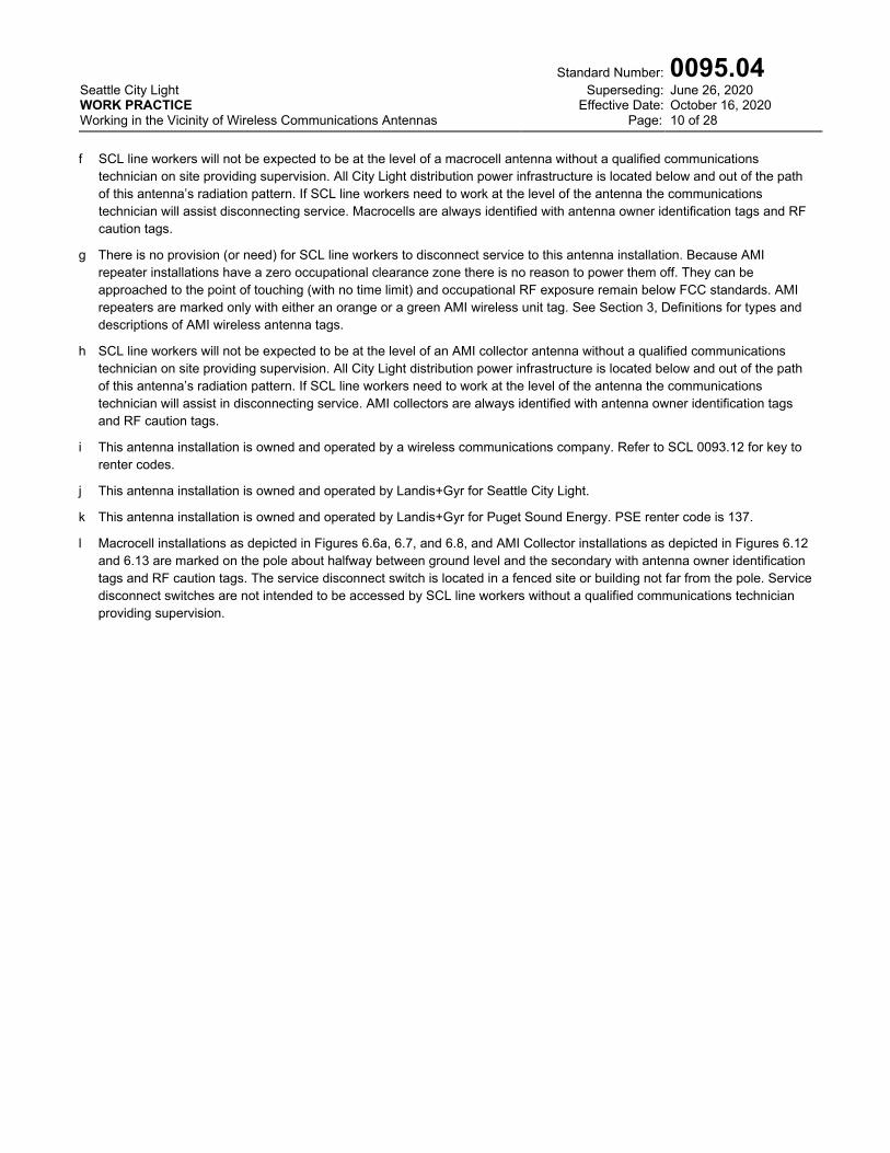
Narda personal RF exposure monitors are purchased by Material Control as Stock No. 014611 and issued from the Tool Room. Narda monitors require special rechargeable batteries, Stock No. 014612. Batteries are not included with the monitors.
The calibration date on a Narda monitor is the date that it was last calibrated. Calibration is recommended every two years.
Figure 5. Narda Monitor

Seattle City Light WORK PRACTICE Working in the Vicinity of Wireless Communications Antennas
Standard Number: Superseding:
Effective Date: Page:
0095.04 June 26, 2020 October 16, 2020 9 of 28
6. Common Wireless Communications Antenna Configurations
6.1 Introduction The purpose of this section is to provide qualified electrical workers and communications technicians with a means to identify and learn more about the wireless communications antennas that they may encounter in the field.
Renter organizations apply marker labels with a unique three-digit code in 1-inch-high lettering at every location to which their equipment is attached.
See SCL 0093.12 for a cross-reference between the three-digit communications codes assigned by SCL Joint Use and communications attachment renter organizations.
Wireless communications antennas fall into the categories described in Table 6.1.
WARNING: Before proceeding, workers should read and understand Section 6, Table 6.1, and its associated notes.
Approaching a wireless communications antenna without taking proper precautions may result in heating of biological tissue.
Table 6.1. Wireless Communications Antenna Categories
Category RF Emissions
Frequency Range Notes Figures Small wireless facility, wood or streetlight pole mount 600–6000 MHz a, c, i 6.2, 6.3, 6.4,.6.5 Strand-mount antenna (except Wi-Fi hotspot) 600–6000 MHz d, i 8a, 8b, 8c Strand-mount antenna, Wi-Fi hotspot 2400–6000 MHz e, i 9 Macrocell 600–6000 MHz f, i, l 6.6a, 6.7, 6.8 AMI Repeater, orange tagged (SCL) 902–928 MHz b, g, j 6.9, 6.10 AMI Repeater, green tagged (PSE) 902–928 MHz b, g, k 6.11 AMI Collector 600–6000 MHz h, j, l 6.12, 6.13
Notes
a Small wireless facilities are also known as small cells or Distributed Antenna System (DAS) equipment
b Repeaters are also known as routers.
c SCL line workers should be able to disconnect service to a small wireless facility by at least one of the means described in Section 7, Step 3. Because these installations have a non-zero occupational clearance zone, the City Light practice is to power them off before working in close proximity. Small wireless facilities are always identified with antenna owner identification tags and RF caution tags.
d SCL line workers can disconnect service to a strand-mount antenna by a clearly marked switch located on the device itself. Because these installations have a non-zero occupational clearance zone, the City Light practice is to power them off before working in close proximity. Strand-mount antennas are always identified with RF notice tags, antenna owner identification tags, and RF caution tags.
e There is no provision (or need) for SCL line workers to disconnect service to this antenna installation. Because Wi-Fi hotspot, strand-mount antennas installations have a zero occupational clearance zone there is no reason to power them off. They can be approached to the point of touching (with no time limit) and occupational RF exposure remain below FCC standards. Wi-Fi hotspot, strand-mount antennas installations are not marked with any kind of signage.
Seattle City Light WORK PRACTICE Working in the Vicinity of Wireless Communications Antennas
Standard Number: Superseding:
Effective Date: Page:
0095.04 June 26, 2020 October 16, 2020 10 of 28
f SCL line workers will not be expected to be at the level of a macrocell antenna without a qualified communications
technician on site providing supervision. All City Light distribution power infrastructure is located below and out of the path of this antenna’s radiation pattern. If SCL line workers need to work at the level of the antenna the communications technician will assist disconnecting service. Macrocells are always identified with antenna owner identification tags and RF caution tags.
g There is no provision (or need) for SCL line workers to disconnect service to this antenna installation. Because AMI repeater installations have a zero occupational clearance zone there is no reason to power them off. They can be approached to the point of touching (with no time limit) and occupational RF exposure remain below FCC standards. AMI repeaters are marked only with either an orange or a green AMI wireless unit tag. See Section 3, Definitions for types and descriptions of AMI wireless antenna tags.
h SCL line workers will not be expected to be at the level of an AMI collector antenna without a qualified communications technician on site providing supervision. All City Light distribution power infrastructure is located below and out of the path of this antenna’s radiation pattern. If SCL line workers need to work at the level of the antenna the communications technician will assist in disconnecting service. AMI collectors are always identified with antenna owner identification tags and RF caution tags.
i This antenna installation is owned and operated by a wireless communications company. Refer to SCL 0093.12 for key to renter codes.
j This antenna installation is owned and operated by Landis+Gyr for Seattle City Light.
k This antenna installation is owned and operated by Landis+Gyr for Puget Sound Energy. PSE renter code is 137.
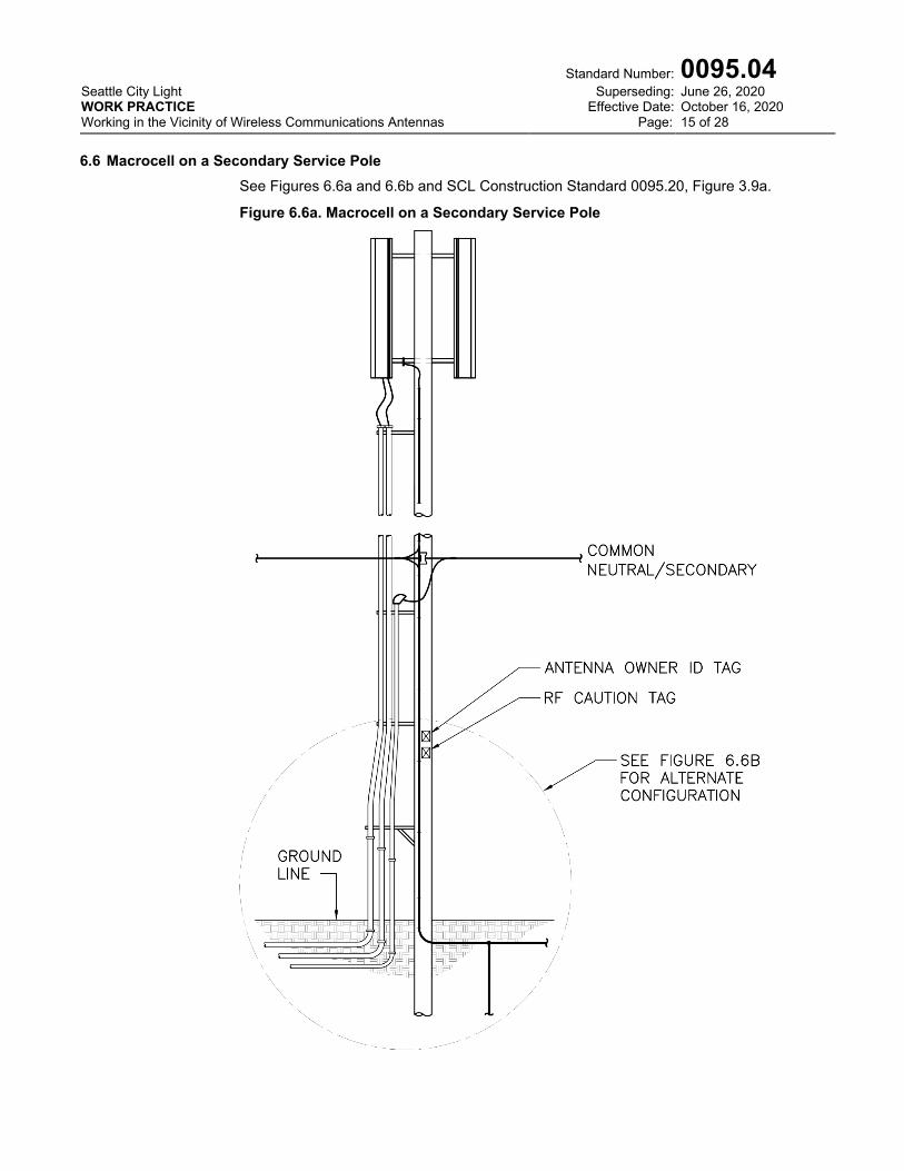
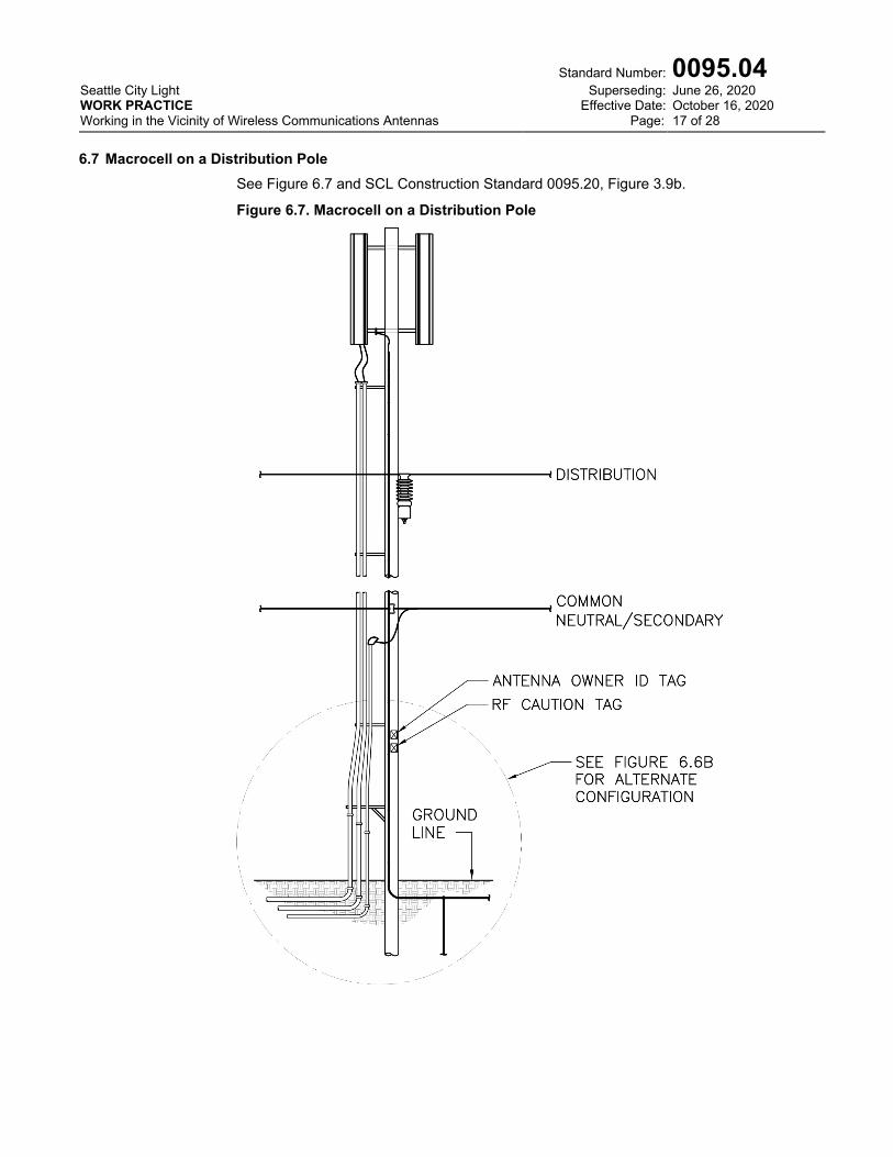
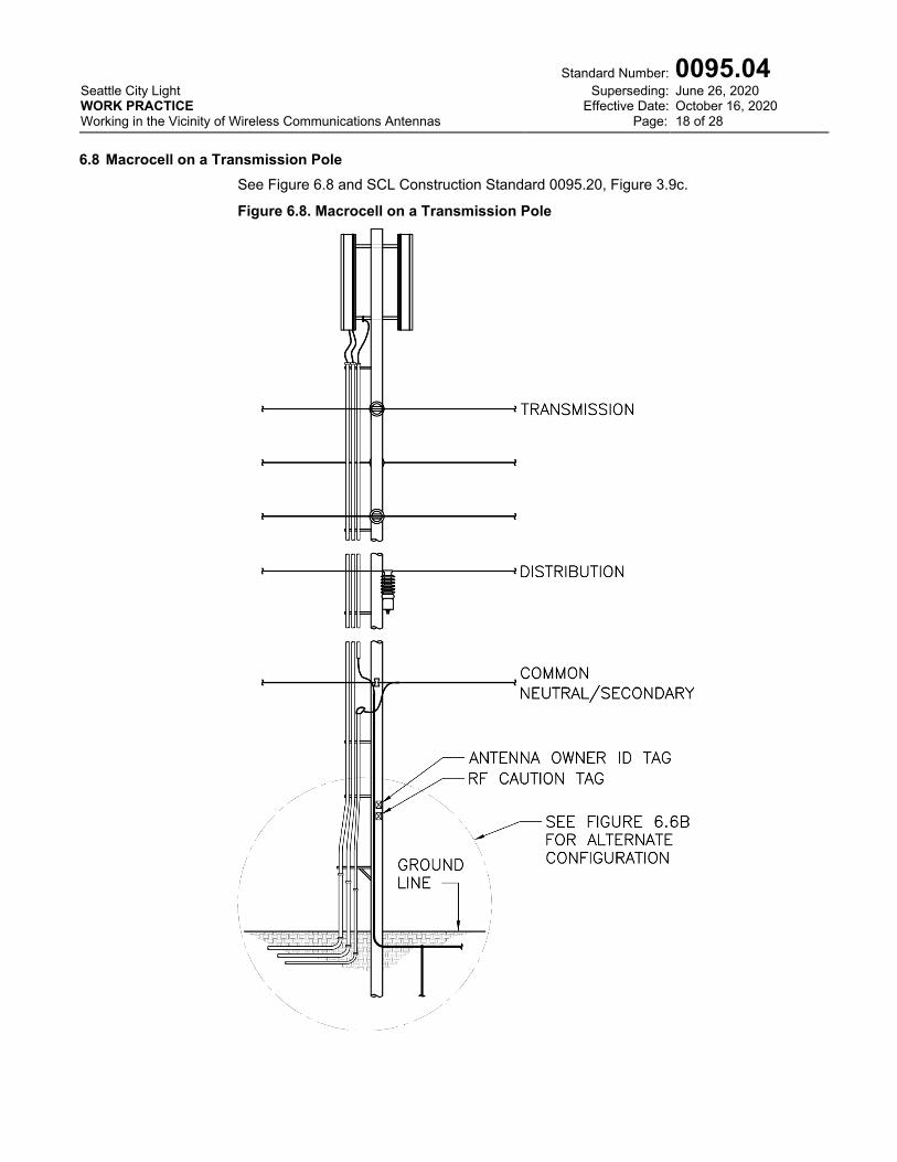
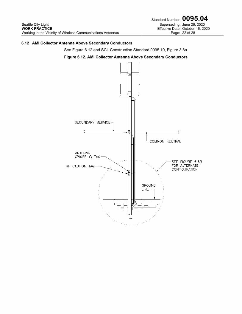
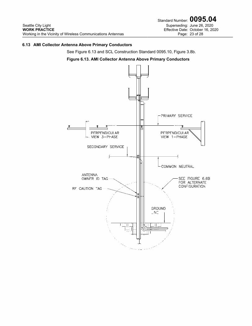
l Macrocell installations as depicted in Figures 6.6a, 6.7, and 6.8, and AMI Collector installations as depicted in Figures 6.12 and 6.13 are marked on the pole about halfway between ground level and the secondary with antenna owner identification tags and RF caution tags. The service disconnect switch is located in a fenced site or building not far from the pole. Service disconnect switches are not intended to be accessed by SCL line workers without a qualified communications technician providing supervision.
Seattle City Light WORK PRACTICE Working in the Vicinity of Wireless Communications Antennas
Standard Number: Superseding:
Effective Date: Page:
0095.04 June 26, 2020 October 16, 2020 11 of 28
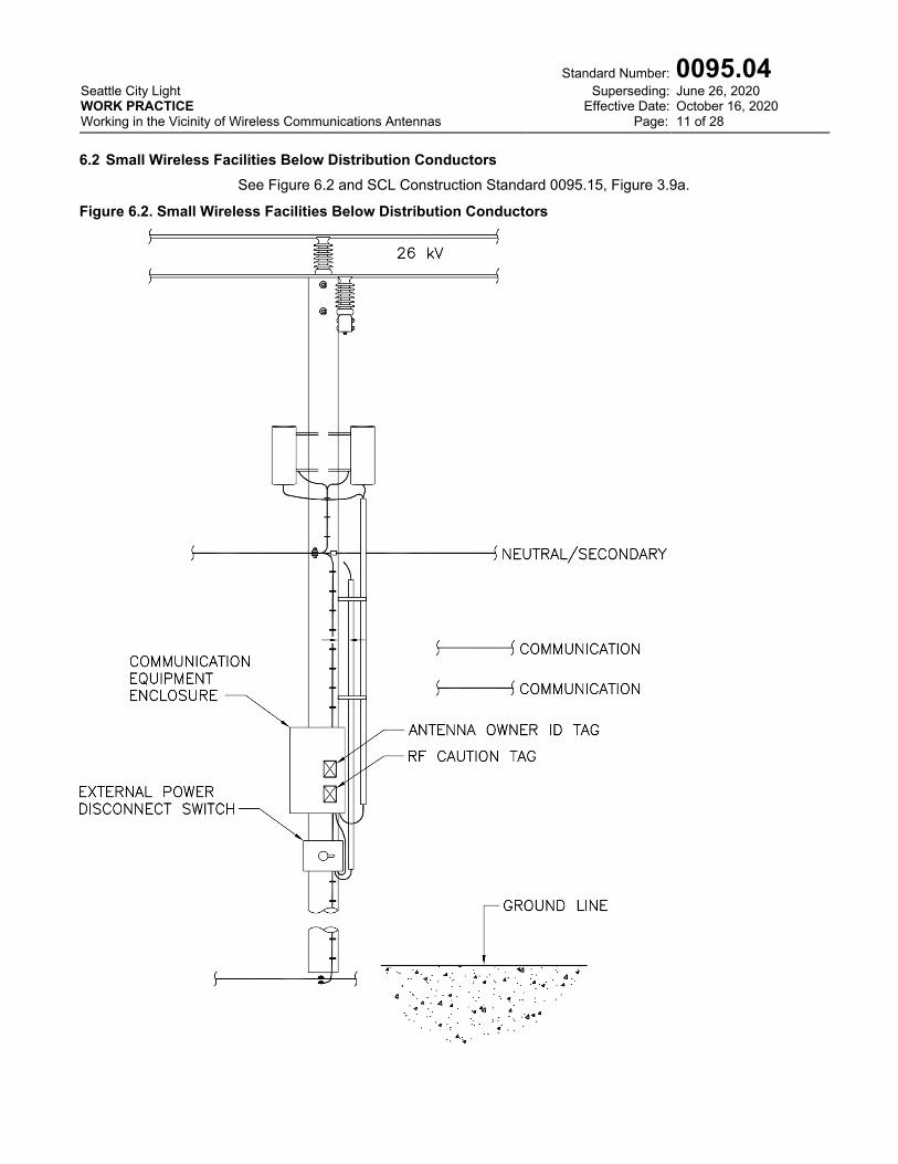
6.2 Small Wireless Facilities Below Distribution Conductors
See Figure 6.2 and SCL Construction Standard 0095.15, Figure 3.9a.
Figure 6.2. Small Wireless Facilities Below Distribution Conductors
Seattle City Light WORK PRACTICE Working in the Vicinity of Wireless Communications Antennas
Standard Number: Superseding:
Effective Date: Page:
0095.04 June 26, 2020 October 16, 2020 12 of 28
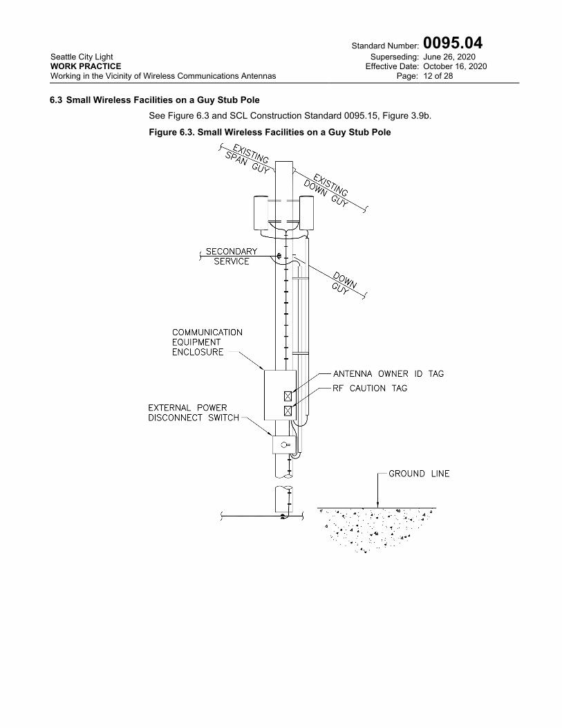
6.3 Small Wireless Facilities on a Guy Stub Pole
See Figure 6.3 and SCL Construction Standard 0095.15, Figure 3.9b.
Figure 6.3. Small Wireless Facilities on a Guy Stub Pole
Seattle City Light WORK PRACTICE Working in the Vicinity of Wireless Communications Antennas
Standard Number: Superseding:
Effective Date: Page:
0095.04 June 26, 2020 October 16, 2020 13 of 28
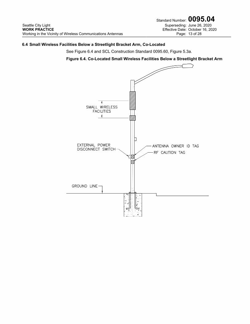
6.4 Small Wireless Facilities Below a Streetlight Bracket Arm, Co-Located
See Figure 6.4 and SCL Construction Standard 0095.60, Figure 5.3a.
Figure 6.4. Co-Located Small Wireless Facilities Below a Streetlight Bracket Arm
Seattle City Light WORK PRACTICE Working in the Vicinity of Wireless Communications Antennas
Standard Number: Superseding:
Effective Date: Page:
0095.04 June 26, 2020 October 16, 2020 14 of 28
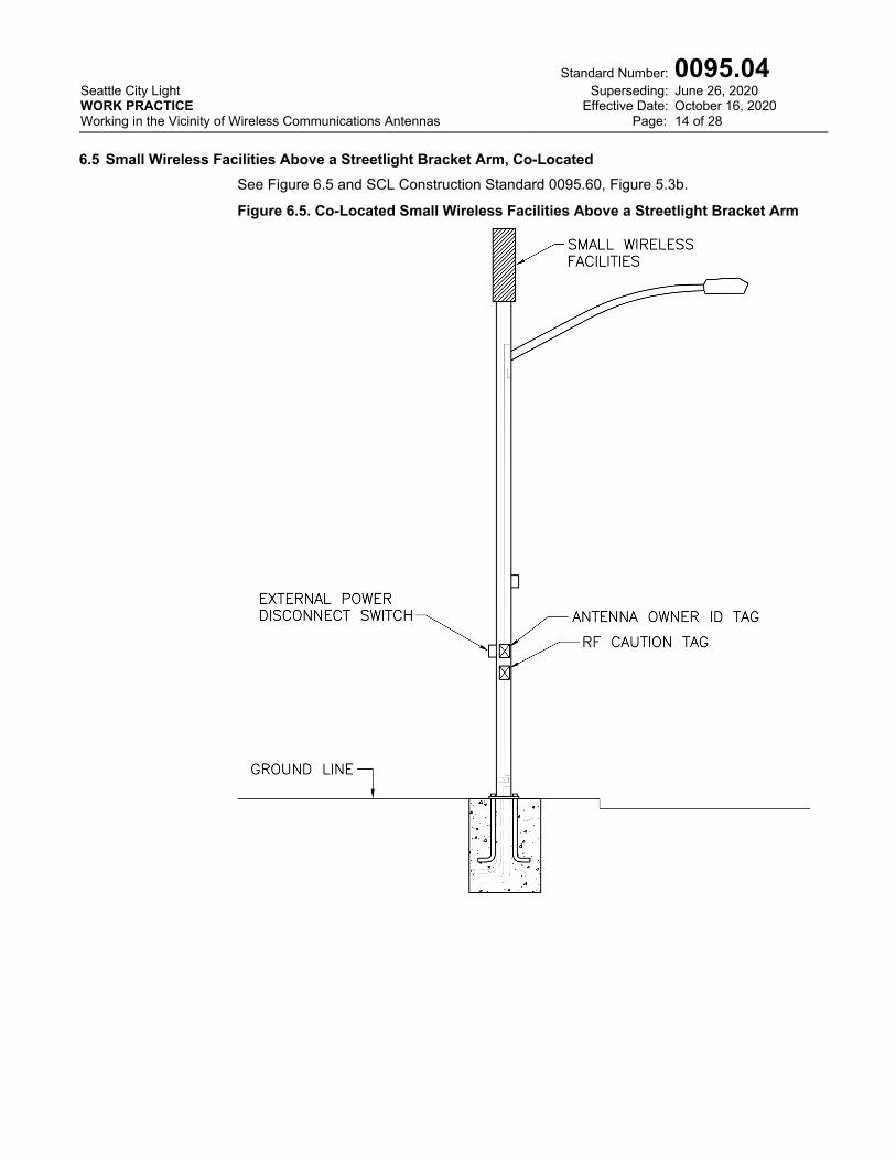
6.5 Small Wireless Facilities Above a Streetlight Bracket Arm, Co-Located
See Figure 6.5 and SCL Construction Standard 0095.60, Figure 5.3b.
Figure 6.5. Co-Located Small Wireless Facilities Above a Streetlight Bracket Arm
Seattle City Light WORK PRACTICE Working in the Vicinity of Wireless Communications Antennas
Standard Number: Superseding:
Effective Date: Page:
0095.04 June 26, 2020 October 16, 2020 15 of 28
6.6 Macrocell on a Secondary Service Pole
See Figures 6.6a and 6.6b and SCL Construction Standard 0095.20, Figure 3.9a.
Figure 6.6a. Macrocell on a Secondary Service Pole

Seattle City Light WORK PRACTICE Working in the Vicinity of Wireless Communications Antennas
Standard Number: Superseding:
Effective Date: Page:
0095.04 June 26, 2020 October 16, 2020 16 of 28
Figure 6.6b. Macrocell on a Secondary Service Pole, Alternate Disconnect
Switch Configuration
Seattle City Light WORK PRACTICE Working in the Vicinity of Wireless Communications Antennas
Standard Number: Superseding:
Effective Date: Page:
0095.04 June 26, 2020 October 16, 2020 17 of 28
6.7 Macrocell on a Distribution Pole
See Figure 6.7 and SCL Construction Standard 0095.20, Figure 3.9b.
Figure 6.7. Macrocell on a Distribution Pole
Seattle City Light WORK PRACTICE Working in the Vicinity of Wireless Communications Antennas
Standard Number: Superseding:
Effective Date: Page:
0095.04 June 26, 2020 October 16, 2020 18 of 28
6.8 Macrocell on a Transmission Pole
See Figure 6.8 and SCL Construction Standard 0095.20, Figure 3.9c.
Figure 6.8. Macrocell on a Transmission Pole

Seattle City Light WORK PRACTICE Working in the Vicinity of Wireless Communications Antennas
Standard Number: Superseding:
Effective Date: Page:
0095.04 June 26, 2020 October 16, 2020 19 of 28
6.9 AMI Repeater on a Wood Pole, 3-ft Bracket Arm
See Figure 6.9 and SCL Construction Standard: 0095.17, Figure 3.4.2.
Figure 6.9. AMI Repeater on a Wood Pole, 3-ft Bracket Arm

Seattle City Light WORK PRACTICE Working in the Vicinity of Wireless Communications Antennas
Standard Number: Superseding:
Effective Date: Page:
0095.04 June 26, 2020 October 16, 2020 20 of 28
6.10 AMI Repeater on a Streetlight Mast
See Figure 6.10 and SCL Construction Standard 0095.17, Figure 3.4.3a.
Figure 6.10. AMI Repeater on a Streetlight Mast
Seattle City Light WORK PRACTICE Working in the Vicinity of Wireless Communications Antennas
Standard Number: Superseding:
Effective Date: Page:
0095.04 June 26, 2020 October 16, 2020 21 of 28
6.11 AMI Repeater on a Streetlight Pole
See Figure 6.11 and SCL Construction Standard 0095.17, Figure 3.4.3b.
Figure 6.11. AMI Repeater on a Streetlight Pole
Seattle City Light WORK PRACTICE Working in the Vicinity of Wireless Communications Antennas
Standard Number: Superseding:
Effective Date: Page:
0095.04 June 26, 2020 October 16, 2020 22 of 28
6.12 AMI Collector Antenna Above Secondary Conductors
See Figure 6.12 and SCL Construction Standard 0095.10, Figure 3.8a.
Figure 6.12. AMI Collector Antenna Above Secondary Conductors
Seattle City Light WORK PRACTICE Working in the Vicinity of Wireless Communications Antennas
Standard Number: Superseding:
Effective Date: Page:
0095.04 June 26, 2020 October 16, 2020 23 of 28
6.13 AMI Collector Antenna Above Primary Conductors
See Figure 6.13 and SCL Construction Standard 0095.10, Figure 3.8b.
Figure 6.13. AMI Collector Antenna Above Primary Conductors

Seattle City Light WORK PRACTICE Working in the Vicinity of Wireless Communications Antennas
Standard Number: Superseding:
Effective Date: Page:
0095.04 June 26, 2020 October 16, 2020 24 of 28
7. General Steps for Working in the Vicinity of Wireless Communications Antennas
These general steps apply to all types of wireless communications antennas, except for devices installed on a communications strand. See Sections 8 and 9 for information on strand-mount devices.
WARNING: Before proceeding, workers should read and understand Section 6, Table 6.1, and its associated notes.
Approaching a wireless communications antenna without taking proper precautions may result in heating of biological tissue.
Individuals should avoid positioning themselves directly in front or close to the antenna. As a general rule, stay 3 feet away from a single antenna.
Step 1 Before the start of work, call the communications operator and inform them of planned activity. The phone number and site ID should be posted on a tag located on or near the communications equipment. It is not necessary to obtain permission or to call back at the completion of work.
Step 2 The first individual planning to approach the wireless communications antenna should check the calibration date on the personal RF exposure monitor, activate it, and attached it to their lapel according to the manufacturer’s instructions.
It is not imperative for subsequent individuals planning to approach the wireless communications antenna wear a personal RF exposure monitor; it is assumed the one exposure monitor will provide indication if the power off switch is defective or otherwise does not work.
Step 3 Power off the wireless communications antenna as soon as practical. Depending on how the antenna is fed, this can be accomplished:
At the pole by opening the service disconnect switch supplying the antenna; At an adjacent pole if multiple units are being fed from a single service disconnect; By unplugging the source connection at the streetlight photocontrol; At a handhole; By operating the switch located on the antenna itself; By unplugging AC power cable at the antenna
See Figure 6.6b.
Step 4 Restore power to the wireless communications antenna after the assigned task is completed.

Seattle City Light WORK PRACTICE Working in the Vicinity of Wireless Communications Antennas
Standard Number: Superseding:
Effective Date: Page:
0095.04 June 26, 2020 October 16, 2020 25 of 28
8. Detailed Steps for Working in the Vicinity of a Strand-Mount Antenna (all except Wi-Fi hotspot)
Installed on a Communications Strand, Example
See Figures 8a and 8b and SCL Construction Standard 0095.30.
Figure 8a. Strand-Mount Antenna (all except Wi-Fi hotspot)
Seattle City Light WORK PRACTICE Working in the Vicinity of Wireless Communications Antennas
Standard Number: Superseding:
Effective Date: Page:
0095.04 June 26, 2020 October 16, 2020 26 of 28
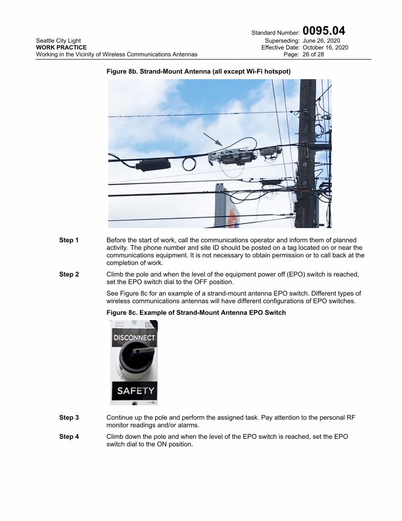
Figure 8b. Strand-Mount Antenna (all except Wi-Fi hotspot)
Step 1 Before the start of work, call the communications operator and inform them of planned activity. The phone number and site ID should be posted on a tag located on or near the communications equipment. It is not necessary to obtain permission or to call back at the completion of work.
Step 2 Climb the pole and when the level of the equipment power off (EPO) switch is reached, set the EPO switch dial to the OFF position.
See Figure 8c for an example of a strand-mount antenna EPO switch. Different types of wireless communications antennas will have different configurations of EPO switches.
Figure 8c. Example of Strand-Mount Antenna EPO Switch
Step 3 Continue up the pole and perform the assigned task. Pay attention to the personal RF monitor readings and/or alarms.
Step 4 Climb down the pole and when the level of the EPO switch is reached, set the EPO switch dial to the ON position.

Seattle City Light WORK PRACTICE Working in the Vicinity of Wireless Communications Antennas
Standard Number: Superseding:
Effective Date: Page:
0095.04 June 26, 2020 October 16, 2020 27 of 28
9. Detailed Steps for Working in the Vicinity of a Strand-Mount, Wi-Fi Hotspot, Example
See Figure 9 and SCL Construction Standard 0095.35, Figure 3.5.
Note: Wi-Fi hotspots are not equipped with service disconnect switches, and do not have signage of any kind.
Figure 9. Strand-Mount Wi-Fi Hotspot
Step 1 Climb the pole.
Step 2 Perform the assigned task. Pay attention to the personal RF monitor readings and/or alarms.
Step 3 Return to the ground.
10. References
C95.1-2005 (Revision of IEEE Std C95.1-1991) – IEEE Standard for Safety Levels with Respect to Human Exposure to Radio Frequency Electromagnetic Fields, 3 kHz to 300 GHz
Federal Communications Commission FCC 18-133 Declaratory Ruling and Third Report and Order, Adopted September 26, 2018, Released September 27, 2018
SCL Construction Standard 0093.12; “Pole Attachments, Identification, and Tagging”
SCL Construction Standard 0094.01; “Communications Enclosures on Wood Poles”
SCL Construction Standard 0095.08; “Wireless Communications Antenna Tags”’
SCL Construction Standard 0095.10; “AMI Collector Antennas”
SCL Construction Standard 0095.15; “Small Wireless Facilities on Wood Poles”
SCL Construction Standard 0095.17; “AMI Repeater Antennas”
SCL Construction Standard 0095.20; “Macrocell Antennas”
SCL Construction Standard 0095.30; “Strand-Mount Antennas, All Except Wi-Fi Hotspot”
SCL Construction Standard 0095.35; “Strand-Mount Antennas, Wi-Fi Hotspot”
SCL Construction Standard 0095.60; “Small Wireless Facilities on Metal Streetlight Poles”

Seattle City Light WORK PRACTICE Working in the Vicinity of Wireless Communications Antennas
Standard Number: Superseding:
Effective Date: Page:
0095.04 June 26, 2020 October 16, 2020 28 of 28
11. Sources
C95.3-2002 (Revision of IEEE Std C95.3-1991) – IEEE Recommended Practice for Measurements and Computations of Radio Frequency Electromagnetic Fields With Respect to Human Exposure to Such Fields, 100 kHz–300 GHz
C95.7-2014 – IEEE Recommended Practice for Radio Frequency Safety Programs, 3 kHz to 300 GHz
FCC - OET Bulletin 56, Fourth Edition, August 1999; Questions and Answers about Biological Effects and Potential Hazards of Radiofrequency Electromagnetic Fields
FCC - OET Bulletin 65, Edition 97-01; Evaluating Compliance with FCC Guidelines for Human Exposure to Radiofrequency Electromagnetic Fields
FCC - RF Safety FAQ; https://www.fcc.gov/engineering-technology/electromagnetic-compatibility-division/radio-frequency-safety/faq/rf-safety#Q2
Haberman, Douglas; SCL Joint Use Strategic Advisor and subject matter expert for 0095.04
IEEE 1654–2009 – IEEE Guide for RF Protection of Personnel Working in the Vicinity of Wireless Communications Antennas Attached to Electric Power Line Structures
Melland, Brandon; SCL Lineworker and subject matter expert for 0095.04
Mott, Kenneth; SCL Communications Electrician and subject matter expert for 0095.04
Neuansourinh, Ponet; SCL Standards Engineer and subject matter expert for 0095.04
Pauley, Amberlynn; SCL Strategic Advisor and subject matter expert for 0095.04
Shipek, John; SCL Standards Supervisor and originator of 0095.04