00016 47600 PRIUS v Homelink Self Dimming Mirror Installation Instructions - PriusChat Shop
description

TOYOTA PRIUS 2013 - FOG LIGHT
Part Number: 00016-47660 Accessory Code: LF10 Conflicts
Southeast Toyota Distributors, LLC
NONE
Kit Contents Item # Quantity Reqd. Description 1 2 Fog Lamps 2 1 Lower grill 3 1 Switch Assembly 4 1 Fog light operation guide
Hardware Bag Contents Item # Quantity Reqd. Description 1 1 Wire harness 2 1 Switch harness 3 2 Relays 4 15 Wire ties 5 2 Phillip head screws 6 2 T-Taps
Additional Items Required For Installation Item # Quantity Reqd. Description
Recommended Tools Safety Tools
Safety Glasses Electrical Tape
Installation Tools 10mm Wrench Phillips Screw Driver Pliers Torque Wrench 48" lbs Side Cutters
Special Chemicals 3M Silicon Sealant
Accessory Service Parts
Service Part
Fog Light Housing R
H
Fog Light Housing LH
Switch
Wire H
arness
Relay
Lower G
rill
Part Number 00016-47660-01 X 00016-47660-02 X 00016-47660-06 X 00016-47660-03 X 00016-47660-05 X 00016-47660-04 X
General Applicability
Recommended Sequence of Application Item # Accessory 1 2 3
Mandatory Legend
STOP: Damage to the vehicle may occur. Do not proceed until process has been complied with.
OPERATOR SAFETY: Use caution to avoid risk of injury CRITICAL PROCESS: Proceed with caution to ensure a quality installation. These points will be audited on a completed vehicle installation TOOLS & EQUIPMENT: This calls out the specific tools and equipment required for this process REVISION MARK: This mark highlights a change in installation with respect to previous issue.
SPECIAL NOTE: After TMS and Safety mandated preparatory steps have been taken, the installation sequence is the suggested method for completing the accessory installation. In some instances the suggested sequence is written for one associate to install and in others the sequence is given as part of a team accessory installation. Unless otherwise stated in the document, the associates may perform the installation steps in any order to make the installation as efficient as possible while maintaining consistent quality. Also some items listed to be removed may not need to be removed if caution is taken to not damage vehicle.
Page 1 of 13

TOYOTA PRIUS FOG LIGHT
Care must be taken when installing this accessory to ensure damage does not occur to the vehicle. The
installation of this accessory should follow approved guidelines to ensure quality installation. These
guidelines can be found in the Accessory Installation Practices document.
This document covers such items as:
• Vehicle Protection (use of covers and blankets, cleaning chemicals, etc)
• Safety (eye protection)
• Vehicle Disassembly / Reassembly (panel removal, part storage, etc)
Preparation
Remove negative battery cable
1. Remove the radiator support opening cover,
by removing 3 clips on top. Then disengage
the 2 claws (picture 1)
Picture 1
2. Use protective tape around the
bumper (left and right sides)
Picture 2
3. Remove the pins located at the left wheel
well: turn the pin 90 degrees
Picture 3
4. Remove screw located next to the pin
Picture 4
5. Repeat steps 3 and 4 for RH side of bumper
6. Remove 7 clips on top of bumper, then
remove 2 bolts at the bottom of it (picture 5)
Southeast Toyota Distributors, LLC Page 2 of 13

TOYOTA PRIUS FOG LIGHT
Picture 5
7. Remove left and right splash shields from
the front of the car. There are 18 x10mm
bolts and 5 plastic push pins (picture 6)
Picture 6
8. Disengage 3 claws (picture 7)
Picture 7
9. On the left side of bumper, disconnect the
turn signal connector. Then dismount
bumper (picture 8)
Picture 8
10. Remove bumper from vehicle
11. Remove the secondary splash shield from
bumper. Remove two screws and then
disengage clips (pictures 9 and 9A)
Picture 9
Picture 9A: disengaging clips
Southeast Toyota Distributors, LLC Page 3 of 13

TOYOTA PRIUS FOG LIGHT
12. Remove factory lower radiator grill from
bumper: there are two retainers on the
outside and 20 claws (pic. 10 & 10A)
Picture 10
Picture 10A: showing the retainer
13. Mount fog lights into lower grill by sliding fog
light tabs into slots and secure other side
with supplied screw (picture 11)
Picture 11
14. Install supplied lower grill to bumper by
reversing step 12. Care should be taken to
assure all tabs are locked into place (pic 12)
Picture 12
15. Locate the ECU mounting bracket on the
top left corner of the fuse block, right of the
brake fluid reservoir (picture 13)
Picture 13
Southeast Toyota Distributors, LLC
Page 4 of 13

TOYOTA PRIUS FOG LIGHT
16. Attach the ring terminal with 2 black wires to
the 10mm bolt off the ECU bracket (see
picture 14)
Picture 14
17. In the hood area, locate the red 12v wire
from fog light harness to inside the fuse
block. Follow the path of the big white wire.
12v red wire will be connected at the end of
the installation (picture 15)
Picture 15
18. Wire tie relay and fuse holder to harness
next to fuse block (picture 16)
Picture 16
19. Route wire along factory harness and
secure with wire ties (picture 17)
Picture 17
20. Locate the large vehicle harness grommet
on the left side. If accessible, cut the
auxiliary wiring access nipple off the
grommet or cut ¼” slit in grommet and push
the red and gray/white wires through
firewall. Note: Extra caution should be taken
not to damage the connectors. Seal with 3M
Silicone sealant (picture 18)
Southeast Toyota Distributors, LLC Page 5 of 13
TOYOTA PRIUS FOG LIGHT
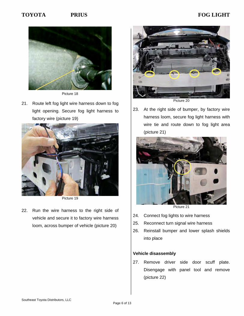
Picture 18
21. Route left fog light wire harness down to fog
light opening. Secure fog light harness to
factory wire (picture 19)
Picture 19
22. Run the wire harness to the right side of
vehicle and secure it to factory wire harness
loom, across bumper of vehicle (picture 20)
Picture 20
23. At the right side of bumper, by factory wire
harness loom, secure fog light harness with
wire tie and route down to fog light area
(picture 21)
Picture 21
24. Connect fog lights to wire harness
25. Reconnect turn signal wire harness
26. Reinstall bumper and lower splash shields
into place
Vehicle disassembly 27. Remove driver side door scuff plate.
Disengage with panel tool and remove
(picture 22)
Southeast Toyota Distributors, LLC Page 6 of 13

TOYOTA PRIUS FOG LIGHT
Picture 22
28. Remove the driver side cowl side trim (see
picture 23 and 23A). Unscrew the cowl side
trim clip. Disengage two (2) clips and
remove the cowl side trim
Picture 23
Picture 23A
29. Remove screw from the bottom left dash
panel (picture 24)
Picture 24
30. Disconnect the hood release cable from
latch, by pulling down the black cable and
releasing it from its location (picture 25)
Picture 25
31. Pull the left top side of the panel away from
dashboard and unplug connectors. Extra
caution should be taking not to pull to hard
and damage connectors (picture 26)
Picture 26
Southeast Toyota Distributors, LLC Page 7 of 13

TOYOTA PRIUS FOG LIGHT
32. Remove 2 screws and push back on tabs to
release lower panel (picture 27)
Picture 27
33. Unplug wire harness and remove panel by
pulling it towards the seat (picture 28)
Picture 28
34. Remove plastic cap from switch knockout of
dash (picture 29)
Picture 29
35. Install switch in empty knockout of dash
(picture 29)
Picture 30
36. NOTE: steps 36~39 are optional. Remove
lower steering wheel cover
37. Push the right and left sides of lower
steering column cover to disengage the 4
claws (picture 31)
Picture 31
38. Insert fingers into the opening of the tilt
leveler of the lower steering column cover to
disengage the claw (picture 32)
Picture 32
Southeast Toyota Distributors, LLC Page 8 of 13

TOYOTA PRIUS FOG LIGHT
39. Turn the steering wheel assembly (pic 33).
Caution: while turning steering wheel make sure not to damage or cut light wires
Picture 33
40. From inside the cabin, locate the wires that
were pushed through in step 20 (picture 34).
It will be the grommet above the gas pedal.
Route wire harness to the left side of
steering wheel. Then plug wire harness to
the switch wire harness, matching colors on
wires (picture 34A)
Picture 34
Picture 34A
41. T-tap orange/black wire from fog light
harness to connector 2C pin 32, green wire.
Pin 32 is the headlight relay wire and is on
the left side of the connector 7th pin up from
bottom of the connector. Connector 2C
located left of the steering column above big
white wire (pictures 35, 37, 38 and 38A)
Picture 35: Connector 2C, Pin 32
42. T-Tap green/black wire from fog light
harness to connector 2C pin 22, yellow wire
which is the DIM relay wire. (picture 36, 37
and 38 and 38A).
Southeast Toyota Distributors, LLC Page 9 of 13

TOYOTA PRIUS FOG LIGHT
Picture 36: Connector 2C Pin 22
Picture 37
Picture 38
Picture 38A: Pin side view
43. Install switch harness into switch (pic. 39)
Picture 39
44. Secure fog light wire harness and relay with
wire ties (picture 40)
Picture 40
45. Reinstall all removed panels
46. Attach fog light 12v red wire to open spade
inside the fuse block. Open spade is located
Southeast Toyota Distributors, LLC Page 10 of 13

TOYOTA PRIUS FOG LIGHT
right above white wire (picture 15). Reattach
cover into place
47. Reconnect negative battery terminal and
torque to: 48 in-lb
Southeast Toyota Distributors, LLC Page 11 of 13

TOYOTA PRIUS FOG LIGHT
Check System for Operation 1. Reconnect battery negative terminal
2. Turn on headlamp low beams, then press
fog light switch to “ON” position. Fog lights
should be working. Fog lights will only
work when the low beam headlamps are
“ON”. Fog lights will NOT work when the
high beam headlamps are “ON”
Fog Light Aiming Traditional fog lights are usually mounted in the
front bumper about 10-24 inches from the ground.
There are two important issues to address when
installing fog lights: the first is to minimize the
amount of return glare into the drivers eyes, and
the other is to minimize the glare into oncoming
eyes. Both of these issues must be accomplished
while putting as much light as possible on the
road.
These fog weather light aiming instructions are
suggestions taken from common practice and the
S.A.E. standard J583. Some modifications to
these instructions may be necessary to minimize
glare.
Visual aim is made with the top of the beam 4
inches below the lamp center at 25 feet with the
lamp facing straight forward (see picture 39)
Picture 39
Southeast Toyota Distributors, LLC Page 12 of 13
TOYOTA PRIUS FOG LIGHT
Southeast Toyota Distributors, LLC
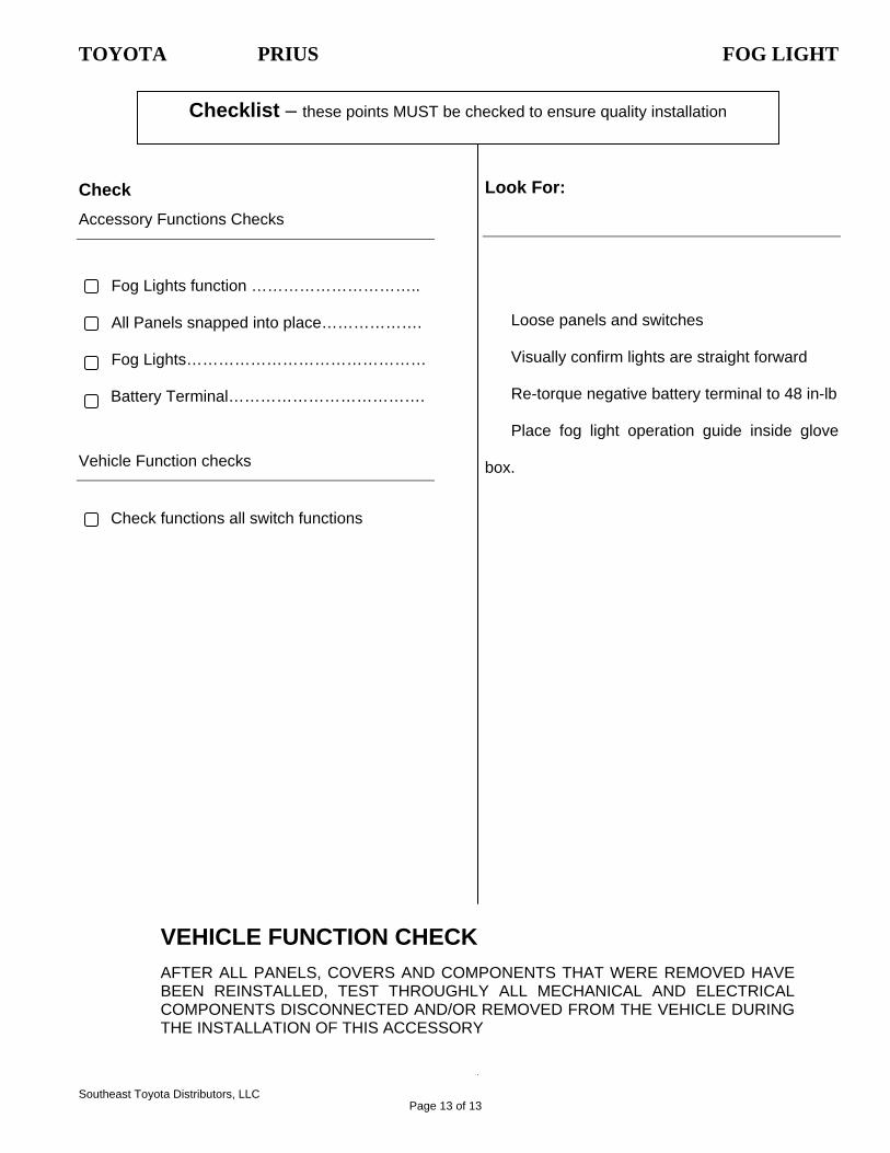
Checklist – these points MUST be checked to ensure quality installation
Look For: Check Accessory Functions Checks
Fog Lights function …………………………..
Loose panels and switches All Panels snapped into place……………….
Visually confirm lights are straight forward Fog Lights………………………………………
Re-torque negative battery terminal to 48 in-lb Battery Terminal……………………………….
Place fog light operation guide inside glove
box.
Vehicle Function checks
Check functions all switch functions
VEHICLE FUNCTION CHECK AFTER ALL PANELS, COVERS AND COMPONENTS THAT WERE REMOVED HAVE BEEN REINSTALLED, TEST THROUGHLY ALL MECHANICAL AND ELECTRICAL COMPONENTS DISCONNECTED AND/OR REMOVED FROM THE VEHICLE DURING THE INSTALLATION OF THIS ACCESSORY
Page 13 of 13